Rego Section 1 - Gas Equipment Company, Inc.
Rego Section 1 - Gas Equipment Company, Inc.
Rego Section 1 - Gas Equipment Company, Inc.
- No tags were found...

You also want an ePaper? Increase the reach of your titles
YUMPU automatically turns print PDFs into web optimized ePapers that Google loves.
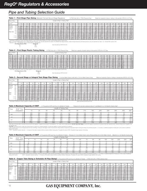
RegO ® Regulators & AccessoriesPipe and Tubing Selection GuideTable 1 – First Stage Pipe Sizing (Between First and Second Stage Regulators) 10 PSIG Inlet with a 1 PSIG Pressure Drop Maximum capacity of pipe or tubing, in thousands of BTU/hr or LP-<strong>Gas</strong>Size of PipeLength of Pipe or Tubing, Feet*or Copper Tubing,<strong>Inc</strong>hes 10 20 30 40 50 60 70 80 90 100 125 150 175 200 225 250 275 300 350 400Copper 3/8 558 383 309 265 235 213 196 182 171 161 142 130 118 111 104 90 89 89 82 76Tubing 1/2 1387 870 700 599 531 481 443 412 386 365 323 293 269 251 235 222 211 201 185 172(O.D.) 5/8 2360 1622 1303 1115 988 896 824 767 719 679 601 546 502 467 438 414 393 375 345 3213/4 3993 2475 2205 1887 1672 1515 1394 1297 1217 1149 1018 923 843 790 740 700 664 634 584 543Pipe Size 1/2 3339 2295 1843 1577 1398 1267 1165 1084 1017 961 852 772 710 660 619 585 556 530 488 4543/4 6982 4799 3854 3298 2923 2649 2437 2267 2127 2009 1780 1613 1484 1381 1296 1224 1162 1109 1020 9491 13153 9040 7259 6213 5507 4989 4590 4270 4007 3785 3354 3039 2796 2601 2441 2305 2190 2089 1922 17881-1/4 27004 18560 14904 12756 11306 10244 9424 8767 8226 7770 6887 6240 5741 5340 5011 4733 4495 4289 3945 36701-1/2 40461 27809 22331 19113 16939 15348 14120 13136 12325 11642 10318 9349 8601 8002 7508 7092 6735 6426 5911 54992 77924 53556 43008 36809 32623 29559 27194 25299 23737 22422 19871 18005 16564 15410 14459 13658 12971 12375 11385 10591* Total length of piping from outlet of first stage regulator to inlet of second state regulator (or to inlet of second stage regulator furthest away).Notes: 1) To allow 2 PSIG pressure drop, multiply total gas demand by .707, and use capacities from table. 2) For different first stage pressures, multiply total gas demand by the following factors, and use capacities from table. Ex: 1,000,000 BTU load at 5 PSI:1,000,000 (1.12) = 1,200,000 BTU then use chart bases on 1,200,000 BTUFirst Stage Pressure PSIGMultiply By20 .844 Data Calculated per NFPA #54 & 5815 .9125 1.120Table 2 – First Stage Plastic Tubing Sizing 10 PSIG Inlet with a 1 PSIG Pressure Drop Maximum capacity of plastic tubing in thousands of BTU/hr of LP-<strong>Gas</strong>Size of PlasticTubingLength of Tubing, Feet*NPS SDR 10 20 30 40 50 60 70 80 90 100 125 150 175 200 225 250 275 300 350 4001/2T 7.00 1387 954 766 655 581 526 484 450 423 399 354 321 295 274 257 243 231 220 203 1891/2 9.33 3901 2681 2153 1843 1633 1480 1361 1267 1188 1122 995 901 829 772 724 684 649 620 570 5303/4 11.00 7811 5369 4311 3690 3270 2963 2726 2536 2379 2248 1992 1805 1660 1545 1499 1369 1300 1241 1141 10621T 11.50 9510 6536 5249 4492 3981 3607 3319 3088 2897 2736 2425 2197 2022 1881 1765 1667 1583 1510 1389 12931T 12.50 10002 6874 5520 4725 4187 3794 3490 3247 3046 2878 2551 2311 2126 1978 1856 1753 1665 1588 1461 13591 11.00 14094 9687 7779 6658 5901 5346 4919 4578 4293 4055 3594 3257 2996 2787 2615 2470 2346 2238 2059 19161 1 /4 10.00 24416 16781 13476 11534 10222 9262 8521 7927 7438 7026 6226 5642 5190 4829 4531 4280 4064 3878 3567 33182 11.00 66251 45534 36566 31295 27737 25131 23120 21509 20181 19063 16895 15308 14084 13102 12293 11612 11028 10521 9680 9005* Total length of piping from outlet of first stage regulator to inlet of second state regulator or to inlet of second stage regulator furthest away.First Stage Pressure PSIGMultiply By20 .84415 .912 Data Calculated per NFPA #54 & 585 1.120Table 3 – Second Stage or Integral Twin Stage Pipe Sizing 11 <strong>Inc</strong>hes Water Column Inlet with a 1/2 <strong>Inc</strong>h Water Column Drop Maximum capacity of pipe or tubing in thousands of BTU/hr of LP-<strong>Gas</strong>Size of PipeLength of Pipe or Tubing, Feet*or Copper Tubing,<strong>Inc</strong>hes 10 20 30 40 50 60 70 80 90 100 125 150 175 200 225 250 275 300 350 400Copper 3/8 49 34 27 23 20 19 –– –– –– –– –– –– –– –– –– –– –– –– –– ––Tubing 1/2 110 76 61 52 46 42 38 36 33 32 –– –– –– –– –– –– –– –– –– ––(O.D.) 5/8 206 151 114 97 86 78 71 67 62 59 –– –– –– –– –– –– –– –– –– ––3/4 348 239 192 164 146 132 120 113 105 100 –– –– –– –– –– –– –– –– –– ––7/8 536 368 296 253 224 203 185 174 161 154 –– –– –– –– –– –– –– –– –– ––Pipe 1/2 291 200 161 137 122 110 102 94 87 84 74 67 62 58 54 51 48 46 43 40Size 3/4 608 418 336 287 255 231 212 198 185 175 155 141 129 120 113 107 101 97 89 831 1146 788 632 541 480 435 400 372 349 330 292 265 244 227 213 201 191 182 167 1561-1/4 2353 1617 1299 1111 985 892 821 764 717 677 600 544 500 465 437 412 392 374 344 3201-1/2 3525 2423 1946 1665 1476 1337 1230 1144 1074 1014 899 815 749 697 654 618 587 560 515 4792 6789 4666 3747 3207 2842 2575 2369 2204 2068 1954 1731 1569 1443 1343 1260 1190 1130 1078 992 923* Total length of piping from outlet of regulator to appliance furthest away. Data Calculated per NFPA #54 & 58Table 4-Maximum Capacity of CSST In Thousands of BTU per hour of undiluted LP-<strong>Gas</strong>es Pressure of 2 psi and a pressure drop of 1 psi (Based on a 1.52 Specific Gravity <strong>Gas</strong>)*Size3/81/2Length of Tubing, FeetEHD** FlowDesignation 10 25 30 40 50 75 80 110 150 200 250 300 400 50013 426 262 238 203 181 147 140 124 101 86 77 69 60 5315 558 347 316 271 243 196 189 169 137 118 105 96 82 7218 927 591 540 469 420 344 333 298 245 213 191 173 151 13519 1106 701 640 554 496 406 393 350 287 248 222 203 175 15823 1735 1120 1027 896 806 663 643 578 477 415 373 343 298 2683/4 25 2168 1384 1266 1100 986 809 768 703 575 501 448 411 355 31930 4097 2560 2331 2012 1794 1457 1410 1256 1021 880 785 716 616 5501 31 4720 2954 2692 2323 2072 1685 1629 1454 1182 1019 910 829 716 638Table does not include effect of pressure drop across the line regulator. If regulator loss exceeds 1/2 psi (based on 13 in. water column outlet pressure), DO NOT USE THIS TABLE. Consult with regulator manufacturer for pressure drops and capacity factors. Pressure drops across a regulator mayvary with flow rate.CAUTION: Capacities shown in table may exceed maximum capacity for a selected regulator. Consult with regulator or tubing manufacturer for guidance.*Table includes losses for four 90-degree bends and two end fittings. Tubing runs with larger number of bends and/or fittings shall be increased by an equivalent length of tubing according to the following equation: L-1.3n where L is additional length (ft) of tubing and n is the number of additionalfittings and/or bends.**EHD –– Equivalent Hydraulic Diameter –– A measure of the relative hydraulic efficiency between different tubing sizes. The greater the value of EHD, the greater the gas capacity of the tubing.Table 5-Maximum Capacity of CSST In Thousands of BTU per hour of undiluted LP-<strong>Gas</strong>es Pressure of 11 <strong>Inc</strong>h Water Column and a Pressure Drop of 0.5 <strong>Inc</strong>h Water Column (Based on a 1.52 Specific Gravity <strong>Gas</strong>)*Size EHD** FlowLength of Tubing, FeetDesignation 5 10 15 20 25 30 40 50 60 70 80 90 100 150 200 250 30013 72 50 39 34 30 28 23 20 19 17 15 15 14 11 9 8 83/815 99 69 55 49 42 39 33 30 26 25 23 22 20 15 14 12 1118 181 129 104 91 82 74 64 58 53 49 45 44 41 31 28 25 231/219 211 150 121 106 94 87 74 66 60 57 52 50 47 36 33 30 2623 355 254 208 183 164 151 131 118 107 99 94 90 85 66 60 53 503/4 25 426 303 248 216 192 177 153 137 126 117 109 102 98 75 69 61 5730 744 521 422 365 325 297 256 227 207 191 178 169 159 123 112 99 901 31 863 605 490 425 379 344 297 265 241 222 208 197 186 143 129 117 107*Table includes losses for four 90-degree bends and two end fittings. Tubing runs with larger number of bends and/or fittings shall be increased by an equivalent length of tubing according to the following equation: L = 1.3n where L is additional length (ft) of tubing and n is the number of additionalfittings and/or bends. **EHD –– Equivalent Hydraulic Diameter –– A measure of the relative hydraulic efficiency between different tubing sizes. The greater the value of EHD, the greater the gas capacity of the tubing.Table 6 – Copper Tube Sizing or Schedule 40 Pipe Sizing* In Thousands of BTU per hour of undiluted LP-<strong>Gas</strong>es2 PSIG inlet with a 1PSIG pressure dropSize of PipeLength of Pipe or Tubing, Feet*or Copper Tubing,<strong>Inc</strong>hes 10 20 30 40 50 60 70 80 90 100 150 200 250 300 350 400 450 500 600 700Copper 3/8 451 310 249 213 189 171 157 146 137 130 104 89 79 72 66 61 58 54 49 45Tubing 1/2 1020 701 563 482 427 387 356 331 311 294 236 202 179 162 149 139 130 123 111 102(O.D.) 5/8 1900 1306 1049 898 795 721 663 617 579 547 439 376 333 302 278 258 242 229 207 1913/4 3215 2210 1774 1519 1346 1219 1122 1044 979 925 743 636 563 511 470 437 410 387 351 323Pipe 1/2 2687 1847 1483 1269 1125 1019 938 872 819 773 621 531 471 427 393 365 343 324 293 270Size 3/4 5619 3862 3101 2654 2352 2131 1961 1824 1712 1617 1298 1111 985 892 821 764 717 677 613 5641 10585 7275 5842 5000 4431 4015 3694 3436 3224 3046 2446 2093 1855 1681 1546 1439 1350 1275 1155 10631-1/4 21731 14936 11994 10265 9098 8243 7584 7055 6620 6253 5021 4298 3809 3451 3175 2954 2771 2618 2372 21821-1/2 32560 22378 17971 15381 13632 12351 11363 10571 9918 9369 7524 6439 5707 5171 4757 4426 4152 3922 3554 32702 62708 43099 34610 29621 26253 23787 21884 20359 19102 18043 14490 12401 10991 9959 9162 8523 7997 7554 6844 629712