Excess Flow, Check, Filler & Vapor Equalizing Valves
Excess Flow, Check, Filler & Vapor Equalizing Valves
Excess Flow, Check, Filler & Vapor Equalizing Valves

Create successful ePaper yourself
Turn your PDF publications into a flip-book with our unique Google optimized e-Paper software.
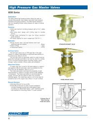
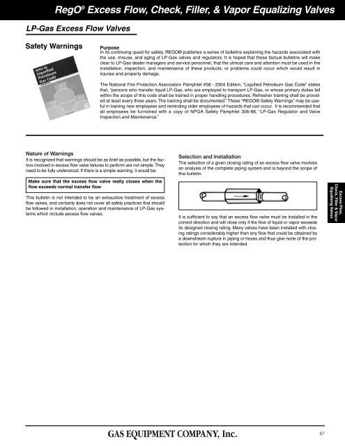
RegO ® <strong>Excess</strong> <strong>Flow</strong>, <strong>Check</strong>, <strong>Filler</strong>, & <strong>Vapor</strong> <strong>Equalizing</strong> <strong>Valves</strong>LP-Gas <strong>Excess</strong> <strong>Flow</strong> <strong>Valves</strong>Safety WarningsPurposeIn its continuing quest for safety, REGO® publishes a series of bulletins explaining the hazards associated withthe use, misuse, and aging of LP-Gas valves and regulators. It is hoped that these factual bulletins will makeclear to LP-Gas dealer managers and service personnel, that the utmost care and attention must be used in theinstallation, inspection, and maintenance of these products, or problems could occur which would result ininjuries and property damage.The National Fire Protection Association Pamphlet #58 - 2004 Edition, “Liquified Petroleum Gas Code” statesthat, “persons who transfer liquid LP-Gas, who are employed to transport LP-Gas, or whose primary duties fallwithin the scope of this code shall be trained in proper handling procedures. Refresher training shall be providedat least every three years. The training shall be documented.” These “REGO® Safety Warnings” may be usefulin training new employees and reminding older employees of hazards that can occur. It is recommended thatall employees be furnished with a copy of NPGA Safety Pamphlet 306-88, “LP-Gas Regulator and ValveInspection and Maintenance.”Nature of WarningsIt is recognized that warnings should be as brief as possible, but the factorsinvolved in excess flow valve failures to perform are not simple. Theyneed to be fully understood. If there is a simple warning, it would be:Make sure that the excess flow valve really closes when theflow exceeds normal transfer flowThis bulletin is not intended to be an exhaustive treatment of excessflow valves, and certainly does not cover all safety practices that shouldbe followed in installation, operation and maintenance of LP-Gas systemswhich include excess flow valves.Selection and InstallationThe selection of a given closing rating of an excess flow valve involvesan analysis of the complete piping system and is beyond the scope ofthis bulletin.It is sufficient to say that an excess flow valve must be installed in thecorrect direction and will close only if the flow of liquid or vapor exceedsits designed closing rating. Many valves have been installed with closingratings considerably higher than any flow that could be obtained bya downstream rupture in piping or hoses and thus give none of the protectionfor which they are intended.<strong>Excess</strong> <strong>Flow</strong>,<strong>Check</strong>, <strong>Filler</strong> & <strong>Vapor</strong><strong>Equalizing</strong> <strong>Valves</strong>67
RegO ® <strong>Excess</strong> <strong>Flow</strong>, <strong>Check</strong>, <strong>Filler</strong>, & <strong>Vapor</strong> <strong>Equalizing</strong> <strong>Valves</strong>Engineered Controls International, Inc. provides excess flow valves with anumber of closing ratings. Engineered Controls International, Inc. obviouslycan take no responsibility for the proper selection or correct installationof any valve.<strong>Excess</strong> flow valves do not provide complete shut-off because there is ableed at the check to permit pressure equalization.Causes of Failure to CloseInstallers, LP-Gas plant managers and service personnel should beaware that the excess flow valves may not close if these conditions arepresent.3. A shut-off valve in the line is only partially open and will notallow enough flow to close the excess flow valve.1. The piping system restrictions (due to pipe length, branches,reduction in pipe size or number of other valves) decrease theflow rate to less than the valve’s closing flow.4. LP-Gas pressure upstream of the excess flow valve, particularlydue to low temperature, is not high enough to produce a closingflow rate.<strong>Excess</strong> <strong>Flow</strong>,<strong>Check</strong>, <strong>Filler</strong> & <strong>Vapor</strong><strong>Equalizing</strong> <strong>Valves</strong>2. The break or damage to the downstream line is not large enoughto allow enough flow to close the valve.5. Foreign matter (such aswelding slag, scale or sludge)is lodged in the valve andprevents closing.Because of these limitations, it is good industry practice to NOT relyentirely on excess flow valves for protection. Installation of emergencyshut-off valves with remote controls is recommended in addition toexcess flow valves.TestingThe National Propane Gas Association Safety Bulletin #113-78 states:“In order to test an excess flow valve in a piping system, the flowthrough the valve must be made to exceed the valve’s closing rating.This testing should only be attempted by trained personnel familiarwith the process. If no one at the facility has experience in propertesting, outside expert help should be obtained. The exact procedureused may vary with the installation, advisability of gas dischargeand availability of equipment.In general, most testing makes use of the fact that excess flow valvesare “surge sensitive” and will close quicker under a sudden flow surgethan under steady flow. A sufficient surge can often be created byusing a quick open/close valve to control sudden, momentary flow intoa tank or piping section containing very low pressure. An audible clickfrom the excess flow valve (and corresponding stoppage of flow) indicatesits closure.A test involving venting gas to the atmosphere is hazardous andmay be impractical, or illegal.Any test of any excess flow valve will not prove that the valve will closein an emergency situation, due to reasons cited before. This test willonly check the valve’s condition, and the flow rate sizing for those testconditions.”General WarningAll REGO® products are mechanical devices that will eventuallybecome inoperative due to wear, contaminants, corrosion and aging ofcomponents made of materials such as metal and rubber.The environment and conditions of use will determine the safe servicelife of these products. Periodic testing at least once a year when tankpressures are low and maintenance, as required, are essential.Because REGO® products have a long and proven record of qualityand service, LP-Gas dealers may forget the hazards that can occurbecause an excess flow valve is used beyond its safe service life. Lifeof an excess flow valve is determined by the environment in which it“lives”. The LPGas dealer knows better than anyone what this environmentis.NOTE: There is a developing trend in state legislation and in proposednational legislation to make the owners of products responsible forreplacing products before they reach the end of their safe useful life.LPGas dealers should be aware of legislation which could effect them.68
RegO ® <strong>Excess</strong> <strong>Flow</strong>, <strong>Check</strong>, <strong>Filler</strong>, & <strong>Vapor</strong> <strong>Equalizing</strong> <strong>Valves</strong>Troubleshooting <strong>Excess</strong> <strong>Flow</strong> Valve InstallationsPeriodical Inspections for <strong>Excess</strong> <strong>Flow</strong> <strong>Valves</strong><strong>Excess</strong> flow valves should be tested and proven at the time ofinstallation and at periodic intervals not to exceed one year.CAUTION: Testing an excess flow valve in the summer whentank pressures are high will not prove that the same valve willalso function under low pressure conditions in the winter. Oncea year testing should be conducted during the winter.The test should include a simulated break in the line by the quickopening of a shut-off valve at the farthest point in the piping that theexcess flow valve is intended to protect. If the excess flow valve closesunder these conditions, it is reasonable to assume that it will closein the event of accidental breakage (clean break) of the piping at anypoint closer to the excess flow valve.2. Line Restriction Too GreatAn excess flow valve installed in atank outlet will not close if the linebeyond it is reduced or if the flowis otherwise restricted by toomany fittings or too long a runbecause the line is incapable ofpassing the amount of LP-Gasnecessary to create an “excess”flow. This condition should be correctedwhen testing a system bysimulating a break at the farthestpossible point and replacing anyrestrictive hose, pipe or fittings.The National Propane Gas Association Safety Bulletin Number 113-78 states:In order to test an excess flow valve in a piping system, the flowthrough the valve must be made to exceed the valve’s closingrating. This testing should only be attempted by trained personnelfamiliar with the process. If no one at the facility has experiencein proper testing, outside expert help should be obtained.The exact procedure used may vary with the installation, advisabilityof gas discharge and availability of equipment.In general, most testing makes use of the fact that excess flow valvesare “surge sensitive” and will close quicker under sudden flow surgethan under steady flow. A sufficient surge can often be created byusing a quick open/close valve to control sudden, momentary flowinto a tank or piping section containing very low pressure. An audibleclick from the excess flow valve (and corresponding stoppage of flow)indicates its closure.A test involving venting gas to the atmosphere is hazardousand may be impractical or illegal.Any test of any excess flow valve will not prove that the valve willclose in an emergency situation, due to reasons cited before. Thistest will only check the valve’s condition and the flow rate sizing forthose test conditions.What prevents excess flow valves from closing when the linebreaks?For one or a combination of the following reasons, excess flow valveshave been prevented from closing in emergencies:1. Not a Clean Break3. Improper Operating Practice4. Improper Selection5. Tampering with <strong>Excess</strong> <strong>Flow</strong> <strong>Valves</strong>A restriction can also be imposedupon the excess flow valve by animproperly opened valve at thetank outlet. The shutoff valveshould be either fully opened orfully closed. If “throttled,” the valvecould reduce the amount of LP-Gas passing through the excessflow valve in a sufficient amountto keep it from closing. Throttlingoperations should not be performedin the lines being protectedby excess flow valves.The many types of excess flowvalves available are designed forspecific jobs. The excess flowvalve selected should remainopen during normal flow but closeat “excess” flow. An inspectionwhich simulates a line break priorto start-up operations will determineif the proper valve has beenselected.Sometimes an operator, annoyedwith frequent closures of anexcess flow valve with too low arating, has mutilated the valve andforgotten to replace it with a properlyrated excess flow valve. Apre-test of the system wouldreveal this and allow the excessflow valve to be replaced.<strong>Excess</strong> <strong>Flow</strong>,<strong>Check</strong>, <strong>Filler</strong> & <strong>Vapor</strong><strong>Equalizing</strong> <strong>Valves</strong>Hoses with a split or tear, andpipe lines not completely severedmay be emitting LP-Gas in anamount insufficient to cause an“excess” flow. The amount of LP-Gas which can escape throughsuch breaks may be even lessthan the flow during normal transferservice and under these conditionsthe excess flow valve couldnot be expected to close.6. Impurities in the LineDirt, weld slag, broken drill taps,and various other foreign objectshave been found jammedbetween the valve disc and valveseat to prevent excess flow valvesfrom closing. A pre-test of the systemwould also discover this.69
RegO ® <strong>Excess</strong> <strong>Flow</strong>, <strong>Check</strong>, <strong>Filler</strong>, & <strong>Vapor</strong> <strong>Equalizing</strong> <strong>Valves</strong>The Limitations of <strong>Excess</strong> <strong>Check</strong> <strong>Valves</strong> for LP-Gas<strong>Excess</strong> <strong>Flow</strong>,<strong>Check</strong>, <strong>Filler</strong> & <strong>Vapor</strong><strong>Equalizing</strong> <strong>Valves</strong><strong>Excess</strong> flow check valves have been of help in limiting gas loss inmany incidents involving breakage of hoses and transfer piping. Thus,they do provide a useful safety function in LP-Gas systems. However,there have also been transfer system accidents where excess flowvalves have been ineffective in controlling gas loss due to a variety ofconditions and to the inherent limitations of these valves. This bulletinexplains what protection excess flow valves can offer, points out conditionswhich can interfere with that protection, and offers suggestionsfor effective excess flow valve installation.An excess flow valve is a protective device to help control the dischargeof product in the event of complete breakage of pipe lines orhose rupture. However, an excess flow valve can only offer limitedprotection from gas discharge, because it will only close under thoseconditions which cause the flow through the valve to exceed its ratedclosing flow, and even when closed it necessarily allows some “bleed”past the valve.An excess flow valve is not designed to close and thus may notprovide protection, if any of the following conditions are present:1. The piping system restrictions (due to pipe length, branches, reductionin pipe size, or number of other valves) decrease the flow rateto less than the valve’s closing flow. (Valve should be selected byclosing flow rating — not just by pipe size).2. The break or damage to the downstream line is not large enough toallow enough flow to close the valve.3. A shut-off valve in the line is only partially open and will not allowenough flow to close the excess flow valve.4. LP-Gas pressure upstream of the excess flow valve, particularlydue to low temperature, is not high enough to produce a closingflow rate.5. Foreign matter (such as welding slag) is lodged in the valve andprevents its closing.6. A buildup of process material (sludge), which may be found inLPGas, may occur over a period of time and cause the valve tostick open.Where excess flow valves are installed, they should be checkedto see that:1. They are installed in the correct direction — the arrow on the valveindicates the shut-off direction.2. The flow rating on the valve is proper for the installation. The ratingmust be above the normal system flow, but not higher than necessaryto prevent “nuisance” closing in normal conditions. If themanufacturer’s catalog information is not sufficient, the valvesuppliers can provide sizing assistance.3. In-line excess flow valves are installed so likely piping damage willoccur downstream of the valve and will not separate the valvefrom the upstream piping.When the excess flow valves can be examined separate from theline (before the installation or if removed for system maintenance),they should be checked to see that the parts are in good conditionand that the poppet can be pushed fully closed.Testing of <strong>Excess</strong> <strong>Flow</strong> <strong>Valves</strong>In order to test an excess flow valve in a piping system, the flowthrough the valve must be made to exceed the valve’s closingrating.This testing should only be attempted by trained personnel familiarwith the process. If no one at the facility has experience inproper testing, outside expert help should be obtained. The exactprocedure used may vary with the installation, advisability of gasdischarge, and availability of equipment.In general, most testing makes use of the fact that excess flowvalves are “surge sensitive” and will close quicker under a suddenflow surge than under steady flow. A sufficient surge can often becreated by using a quick-closing valve to control sudden, momentaryflow into a tank or piping section containing very low pressure.An audible click from the excess flow valve (and correspondingstoppage of flow) indicates its closure.A test involving venting gas to the atmosphere is hazardous andmay be impractical, or illegal.7. The piping break or damage occurs upstream of an in-line excessflow valve, so the escaping product is not passing through thevalve.8. The flow through the valve is in the wrong direction. (<strong>Excess</strong> flowvalves only respond to flow in one direction.)Any test of any excess flow valve will not prove that the valve willclose in an emergency situation, due to reasons cited before. Thistest will only check the valve’s condition, and the flow rate sizingfor those test conditions.For additional information on excess flow valves and other meansof shut-off protection, contact REGO® and refer to NFPA 58.9.The excess flow valve has been damaged, or is otherwise not inoperating condition.Because of these limitations of excess flow valves, they should not berelied upon as the only means of controlling the escape of product inthe event of piping damage. When possible, shut-off protection byquick closing valves, with shut-off controls accessible in spite of likelyline damage, should be provided in addition to, or instead of excessflow valves.Prepared byNATIONAL PROPANE GAS ASSOCIATIONThe purpose of this bulletin is to set forth general safety practices forthe installation, operation, and maintenance of LP-Gas equipment. It isnot intended to be an exhaustive treatment of the subject, and shouldnot be interpreted as precluding other procedures which wouldenhance safe LP-Gas operations. The National Propane GasAssociation assumes no liability for reliance on the contents of thisbulletin.70
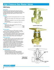
RegO ® <strong>Excess</strong> <strong>Flow</strong>, <strong>Check</strong>, <strong>Filler</strong>, & <strong>Vapor</strong> <strong>Equalizing</strong> <strong>Valves</strong><strong>Excess</strong> <strong>Flow</strong> <strong>Valves</strong>General InformationRegO® <strong>Excess</strong> <strong>Flow</strong> <strong>Valves</strong> have been designed, developed, andmanufactured for a wide variety of industry needs for more than threedecades.Throughout the years, those concerned with installing and operatingbulk plant facilities have looked to RegO® products with confidence forreliable, long-lasting valves as required by the National Fire ProtectionAssociation (NFPA) Standards 58 and 59, as well as any state, provincial,and local regulations.It is a responsibility we have not taken lightly. RegO® products continueto not only assess the most effective designs, but anticipate andmeet the industry’s changing requirements. Toward that goal, RegO®products include over fifty different types and sizes of excess flowvalves (most of which are listed by Underwriters Laboratories) to meetthe needs of the LP-Gas and anhydrous ammonia industries.How They Work<strong>Excess</strong> flow valves permit the flow of liquid or vapor in either direction.This flow is controlled in only one direction (the direction of the arrowstamped on the valve). If the flow in that direction exceeds a predeterminedrate (shown in this catalog for each valve), the valve automaticallycloses.The valve disc is held in the open position by a spring. When the flowcreates a pressure drop across the valve disc that overcomes the presetload on the spring, the valve disc moves to the closed position. It remainsclosed until the force on both sides of the valve disc are approximatelyequal (a small bleed hole in the disc of each valve permits equalization),then the spring automatically reopens the valve. When a line is completelybroken, the pressure cannot equalize and the excess flow valveremains closed until the line is repaired. Because the bleed hole in eachvalve disc permits equalization of pressure, excess flow valves do notprovide a 100 percent type shut-off.An Explanation and WarningAn excess flow valve is a spring-loaded check valve which will closeonly when the flow of fluid through the valve generates sufficient forceto overcome the power of the spring holding it open. Each valve has aclosing rating in gallons per minute and CFH/air.Proper InstallationSince excess flow valves depend on flow in order to close, the line downstreamof the excess flow valve should be large enough not to excessivelyrestrict the flow. If the piping is too small, unusually long or restrictedby too many elbows, tees and other fittings, considerationshould be given to the use of larger size pipe fittings.The selection of a proper closing rating is critical. It requires atechnical understanding of the flow characteristics of the pipingsystem, including restrictions of the piping and other valves andfittings downstream of the excess flow valve.System designers and operating people must understand why anexcess flow valve, which remains open in normal operations, may failto close when an accident occurs.An excess flow valve in a pump suction line cannot be expected to closein the case of a clean break in the line beyond the pump, as the pumpconstitutes too great a restriction, even if running.Good piping practices dictate the selection of an excess flow valve with arated closing flow of approximately 50 percent greater than the anticipatednormal flow. This is important because valves which have a ratedclosing flow very close to the normal flow may chatter or slug closedwhen surges in the line occur during normal operation, or due to therapid opening of a control valve.<strong>Excess</strong> <strong>Flow</strong>,<strong>Check</strong>, <strong>Filler</strong> & <strong>Vapor</strong><strong>Equalizing</strong> <strong>Valves</strong>Warning: A downstream break in piping or hoses may notresult in sufficient flow to close the valve.All installations must be in accordance with NFPA Standards 58 and 59,as well as state, provincial and local regulations.Cotter pin prevents loss of springretainer due to vibration in service.Spring retainer.Stainless steel spring for consistentclosing flow, long service life.Welded for strength.Precision machining.Generous flow channels for lowestpressure drop are particularlyimportant in pump suction lines.71
RegO ® <strong>Excess</strong> <strong>Flow</strong>, <strong>Check</strong>, <strong>Filler</strong>, & <strong>Vapor</strong> <strong>Equalizing</strong> <strong>Valves</strong><strong>Excess</strong> <strong>Flow</strong> <strong>Valves</strong> for Liquid or <strong>Vapor</strong> ServiceDesigned for top mounting in storage tank manhole covers for liquid orvapor applications. The tapped inlet allows for an optional 1” NPT dippipe connection to withdraw liquid from the top of the tank.UL®The 1519C4 is designed for installation in long line or branch pipingapplications.1519C21519C4PartNumberInletConnectionNPTOutletConnection F.NPTWrench HexFlatsEffectiveLength(Approx.)Threaded Endto PortFillingConnectionF. NPTLiquid(GPM Propane)Approximate Closing <strong>Flow</strong>s* 1” Female Dip Pipe Connection** Based on horizontal installation of excess flow valve. <strong>Flow</strong>s are slightly more when valves are installed with outlet up; slightly less when installed with outlet down.NOTE: Multiply flow rate by .94 to determine liquid butane flow.<strong>Vapor</strong> SCFH (Propane)25 PSIG Inlet 100 PSIG Inlet1519C2 1½” Male* 1” 2¼” 2 1 ⁄16” 2 11 ⁄16” 1” 25 5,000 8,8001519C4 2” Female 2” 3” 4 9 ⁄16” - 2” 170 28,590 48,600<strong>Excess</strong> <strong>Flow</strong>,<strong>Check</strong>, <strong>Filler</strong> & <strong>Vapor</strong><strong>Equalizing</strong> <strong>Valves</strong><strong>Excess</strong> <strong>Flow</strong> <strong>Valves</strong> for Liquid or <strong>Vapor</strong>Line ServiceDesigned for top installation, in any position, in liquid or vapor servicelines. They are intended for long lines or branch piping where tankmounted excess flow valves cannot suffice.UL®1519A2, 1519A3, 1519A4, 1519B4,A1519A2, A1519A4, A1519B4A1519A6BrassInlet OutletWrench Hex LengthApproximate Closing <strong>Flow</strong>s*Part Numberor Connection Connection F.Flats (Approx)SteelNPT NPT25 PSIG Inlet 100 PSIG Inlet1519A2Brass1” 1” 1¾” 3 15 ⁄16” 25 5,000 8,800A1519A2Steel1519A31½” 1½” 2¼” 4” 60 11,500 20,200Brass1519A4100 19,000 34,500A1519A4Steel2” 2” 3” 4 9 ⁄16”1519B4Brass133 27,700 50,300A1519B4SteelA1519A6 3” 3” 4” 6 17 ⁄32” 225 45,000 82,000* Based on horizontal installation of excess flow valve. <strong>Flow</strong>s are slightly more when valves are installed with outlet up; slightly less when installed with outlet down.NOTE: Multiply flow rate by .94 to determine liquid butane flow and by .90 to determine liquid anhydrous ammonia flow.72
RegO ® <strong>Excess</strong> <strong>Flow</strong>, <strong>Check</strong>, <strong>Filler</strong>, & <strong>Vapor</strong> <strong>Equalizing</strong> <strong>Valves</strong><strong>Excess</strong> <strong>Flow</strong> <strong>Valves</strong> for Liquid or <strong>Vapor</strong>Designed for liquid or vapor use for filling, withdrawal and vaporequalizing in container or line applications. They are intended for longlines or branch piping where tank-mounted excess flow valves areinadequate.UL®Approximate Closing <strong>Flow</strong>*Inlet Outlet Wrench EffectivePart Brass orConnection Connection Hex LengthNumber SteelLiquid (GPM <strong>Vapor</strong> SCFH (Propane)(M. NPT) (F. NPT) Flats (Approx.) Propane) 25 PSIG Inlet 100 PSIG Inlet124724 1,050 1,7003272E 10 2,100 3,700Brass3272F ¾” ¾” 1 3 ⁄8” 1 3 ⁄8” 15 2,800 5,0003272GA3272G Steel20 3,700 6,9003282A30 5,850 10,0003282B Brass40 7,600 13,6001¼” 1¼” 2” 1 15 ⁄16”3282C50 9,000 16,300A3282C Steel757490 15,200 28,1001½” 1½” 2¼” 1¾”7574L Brass70 14,000 25,0003292AA3292A Steel75 14,200 24,8003292B Brass 2” 2” 2 7 ⁄8” 1 7 ⁄8”100 18,100 32,700A3292BSteelA3292C 122 22,100 37,600* Based on horizontal installation of excess flow valve. <strong>Flow</strong>s are slightly more when valves are installed with outlet up; slightly less when installed with outlet down.<strong>Excess</strong> <strong>Flow</strong> <strong>Valves</strong> for Container Service<strong>Excess</strong> <strong>Flow</strong>,<strong>Check</strong>, <strong>Filler</strong> & <strong>Vapor</strong><strong>Equalizing</strong> <strong>Valves</strong>Designed for mounting in threaded full or half couplings in container installations.They may be used for filling, withdrawal or vapor equalizing applications.The exceptionally low pressure drop makes them ideal for pumpsuction lines. If a riser pipe to the vapor space is used with these valves, theminimum inside diameter of the riser pipe must be at least two times thevalve thread size in order not to restrict flow to the side inlet ports.UL®PartNumberFor Use WithThis TypeCouplingInletConnectionM. NPTOutletConnectionNPTWrench HexFlatsEffective Length(Approx.)Liquid (GPMPropane)Approximate Closing <strong>Flow</strong>** Based on horizontal installation of excess flow valve. <strong>Flow</strong>s are slightly more when valves are installed with outlet up; slightly less when installed with outlet down.<strong>Vapor</strong> SCFH (Propane)25 PSIG Inlet 100 PSIG InletA8523 Half ¾” ¾” Male 1 1 ⁄8” 1¾” 15 5,170 8,800A8525 Half 1¼” 1¼” Male 1¾” 2 1 ⁄8” 35 12,540 21,560A7537L4 Half75 13,000 25,600A7537L4FA7537N4A7537N4FA7537P4A7537P4FA7539R6A7539R6FA7539T6A7539T6FA7539V6A7539V6FFullHalfFullHalfFullHalfFullHalfFullHalfFull2”3”2” Maleand1¼” Female3” Maleand2” Female2 5 ⁄8” 2½”3¾” 3 1 ⁄8”125 25,000 42,500150 30,500 52,000150 32,100 55,500200 39,400 68,300250 51,100 88,70073
RegO ® <strong>Excess</strong> <strong>Flow</strong>, <strong>Check</strong>, <strong>Filler</strong>, & <strong>Vapor</strong> <strong>Equalizing</strong> <strong>Valves</strong><strong>Excess</strong> <strong>Flow</strong> <strong>Valves</strong> for Liquid or <strong>Vapor</strong> WithdrawalThese valves are designed for bottom mounting in consumer storagetanks for liquid service. They may also be top mounted for vapor service.These valves are designed especially for use with RegO ® globe andangle valves.UL®A8013D2723CPart NumberInlet OutletEffective ThreadedApproximate Closing <strong>Flow</strong>**WrenchConnection ConnectionLength End ToHex FlatsLiquid<strong>Vapor</strong> SCFH (Propane)M. NPT NPT(Approx.) Port (GPM Propane) 25 PSIG Inlet 100 PSIG InletA8013D¾”9⁄16”39A8013DA 1¼” 1” 1 7 ⁄8”21⁄32” -448,700 14,700A8013DB 1¼”11⁄16” 55 10,900 19,3002723C 1¼” ¾” 1 11 ⁄16” 1¼” 3 3 ⁄16” 20 3,900 6,900* ¾” F. NPT Dip Pipe Connection** Based on horizontal installation of excess flow valve. <strong>Flow</strong>s are slightly more when valves are installed with outlet up; slightly less when installed with outlet down.NOTE: Multiply flow rate by .94 to determine liquid butane flow and by .90 to determine liquid anhydrous ammonia flow.<strong>Excess</strong> <strong>Flow</strong> Valve for Pressure GaugesDesigned for container use in pressure gauge installations to minimizeexcess gas discharge in the event the pressure gauge is sheared. Asuitable shut-off valve should be installed between this valve and thepressure gauge to allow convenient gauge replacement.UL®<strong>Excess</strong> <strong>Flow</strong>,<strong>Check</strong>, <strong>Filler</strong> & <strong>Vapor</strong><strong>Equalizing</strong> <strong>Valves</strong>Approximate Closing <strong>Flow</strong>*Inlet Outlet Wrench Effective ThreadedPartConnection Connection Hex Length End ToLiquid <strong>Vapor</strong> SCFH (Propane)NumberM. NPT F. NPT Flats (Approx.) Port(GPMPropane)25 PSIG Inlet 100 PSIG Inlet2884D ¾” ¼” 1 1 ⁄16”111¼” ⁄16” N/A 60 110* Based on horizontal installation of excess flow valve. <strong>Flow</strong>s are slightly more when valves are installed with outlet up; slightly less when installed with outlet down.NOTE: Multiply flow rate by .94 to determine liquid butane flow.<strong>Excess</strong> <strong>Flow</strong> Valve for DOT CylindersDesigned for use on portable systems with vapor or liquid includingtorches, heaters, lead melting burners, tar and asphalt burners, wallpapersteamers and other applications involving portable DOT cylinders. ThePOL inlet attaches directly to the cylinder valve and the outlet mounts tothe regulator.UL®PartNumberInletConnectionOutletConnectionWrenchHex FlatsEffectiveLength(Approx.)Liquid(GPM Propane)Approximate Closing <strong>Flow</strong>*<strong>Vapor</strong> SCFH (Propane)25 PSIG Inlet 100 PSIG Inlet3199W Male POL ¼” 7⁄8” 1 1 ⁄16” .95 265 500* Based on horizontal installation of excess flow valve. <strong>Flow</strong>s are slightly more when valves are installed with outlet up; slightly less when installed with outlet down.NOTE: Multiply flow rate by .94 to determine liquid butane flow.75
RegO ® <strong>Excess</strong> <strong>Flow</strong>, <strong>Check</strong>, <strong>Filler</strong>, & <strong>Vapor</strong> <strong>Equalizing</strong> <strong>Valves</strong>Chek-Lok® <strong>Excess</strong> <strong>Flow</strong> <strong>Valves</strong>Designed to provide a convenient means of withdrawing liquid fromstationary containers prior to moving the container.NFPA Pamphlet 58 standards require: 1) containers with 125 gallonswater capacity, or more, have a connection for liquid evacuation whichis at least 3 /4” NPT, and 2) containers designed for stationary use, haveno more propane than 5% of their water capacity in liquid form duringtransportation. These rules apply to containers manufactured afterJuly 1, 1961.The Chek-Lok ® permits one transfer shut-off valve with an adapter tobe used interchangeably on a number of tanks. With a Chek-Lok ® oneach tank and a high capacity RegO ® 7550P Series transfer valveand adapter on all your service and delivery trucks – the need forindividual transfer valves is eliminated. This provides a substantialsavings without sacrificing safety.Chek-Lok® Operation<strong>Excess</strong> <strong>Flow</strong>,<strong>Check</strong>, <strong>Filler</strong> & <strong>Vapor</strong><strong>Equalizing</strong> <strong>Valves</strong>Instructions to Open Chek-Lok®1 Loosen cap to vent any accumulated LP-Gas from the Chek-Lok.After venting stops, remove the cap. If venting does not stop,retighten the cap and use other approved means to withdraw liquidfrom the container.NOTE: Use a suitable size wrench when removing the cap andadapter from the Chek-Lok. Do not allow the Chek-Lok to un-threadfrom the tank during removal. When necessary, use a secondwrench to secure the Chek-Lok in position.2 Before beginning withdrawal, securely connect an 7550PREGO®angle valve or suitable shut-off valve to the adapter. Fully open theshut-off valve – the valve’s handwheel must be fully opened beforeconnecting adapter to tank.3 Completely thread the adapter and shut-off valve assembly ontothe Chek-Lok by turning adapter’s coupling nut clockwise until it istight. Immediately close the shut-off valve. Listen for an audibleclick to signal that the Chek-Lok has opened and is actuated for liquidwithdrawal. The flow can now be controlled by the transfer valve.4<strong>Check</strong> the coupling nut and adapter assembly for leaks using asuitable leak detection solution.If the Chek-Lok fails to open after following this procedure, the pressuredownstream of the shut-off valve should be increased toequalize pressure in the Chek-Lok. It is simple to equalize pressuresusing vapor from either the vapor return valve or servicevalve, or from a hose end valve connected to the delivery truck.Instructions to Close Chek-Lok®1234To re-lock the Chek-Lok, container pressure must be in excess of35 PSIG. Close shut-off valve and disconnect the hose or piping.Open shut-off valve fully. Liquid discharging to the atmosphereshould cause the excess flow feature of the Chek-Lok to close,provided tank pressure is 35 PSIG or more.If, for any reason, the excess flow valve does not close, the shut-offvalve must be closed immediately and must not be removed untilthe system can be evacuated and the unit repaired.After the excess flow valve closes, remove the Adapter and Shut-Off Valve Assembly.Clean face of Chek-Lok and install the Cap with a gasket. IMPOR-TANT: Only use the proper Chek-Lok Cap. Do not use a standardpipe cap.Connecting the 7590Uor 7591U Chek-Lok®7550P Angle Valve7590U-10 Adapter7590U or 7591U Chek-Lok ®Connecting the7572FC or 7580FCChek-Lok®7550P Angle Valve7572-14A Adapter7572FC or 7580FC Chek-Lok ®In the absence of a 7550P transfer valve, a ¾” A7505A Globe Valve orA7506AP Angle Valve may be used. Follow the above proceduresusing the 7572C-15A adapter instead of the 7572C-14A. Use aREGO® 7550P without an adapter in an emergency only.CAUTION: Always wear approved protective gloves when working with the Chek-Lok ® .Do not vent LP-Gas near possible source of ignition.Chek-Lok® MountingChek-Lok® <strong>Valves</strong> may be either top mounted with a dip tube orbottom mounted. For bottom mounting, it is preferable to positionthe coupling in the head or slightly off of the bottom. This helpsprevent the accumulation of sludge, etc. around the valve whichcould affect the proper operation of the excess flow valve.76
RegO ® <strong>Excess</strong> <strong>Flow</strong>, <strong>Check</strong>, <strong>Filler</strong>, & <strong>Vapor</strong> <strong>Equalizing</strong> <strong>Valves</strong>7590U and 7591U Chek-Lok® <strong>Valves</strong>Chek-Lok® <strong>Excess</strong> <strong>Flow</strong> <strong>Valves</strong> are designed to provide a convenientmeans of withdrawing liquid from stationary containers prior to movingthe container. The Chek-Lok® permits one transfer shut-off valve withan adapter to be used interchangeably on a number of tanks.The 7590U and 7591U Chek-Loks® are also designed for use on permanentinstallations provided the excess flow valve is sized properly forthe system and piping. NOTE: In some cases, it may be necessary touse an in-line excess flow valve to protect the downstream piping. Thisvalve is not recommended for use as a liquid source for pumps.7590U with CapUL®Chek-Lok® NumberInlet ConnectionOutletConnectionBody Wrench HexFlatsApproximateEffective LengthCap Wrench HexFlatsApproximate Closing<strong>Flow</strong>, LiquidGPM (Propane)*7590U¾” M. NPT1 5 ⁄8” 1 7 ⁄16”207591U 1¼” M. NPT1 5 ⁄8” UNF1¾” 1 11 ⁄16”1 5 ⁄16”35* Based on horizontal installation of excess flow valve. <strong>Flow</strong>s are slightly more when valves are installed with outlet up, and slightly less when installed with outlet down.Note: Multiply flow rate by .94 to determine liquid butane flow.Chek-Lok® Liquid Evacuation Adapter for7590U and 7591U <strong>Valves</strong>Designed specifically for use with RegO ® 7590U and 7591U Chek-Lok ®<strong>Excess</strong> <strong>Flow</strong> <strong>Valves</strong>. Adapter’s operating handle opens and closes equalizingstem in the Chek-Lok ® valve. Eliminates gas flow through Chek-Lok ®valve when installing or removing adapter. Use of RegO ® adapter ensuresproper connections and opening of the check mechanism.UL®<strong>Excess</strong> <strong>Flow</strong>,<strong>Check</strong>, <strong>Filler</strong> & <strong>Vapor</strong><strong>Equalizing</strong> <strong>Valves</strong>Adapter NumberInletConnectionOutletConnectionWrench HexFlatsChek-Lok®Number7590U-20 1 5 ⁄8” F. NPT ¾” F. NPT 1¾” F. NPT 4 1 ⁄8” F. NPTUnion Style Adapters for 7590U and 7591U <strong>Valves</strong>The 7590U-10 adapter must be used to connect to the 7590U and7591U Chek-Lok. This insures a proper connection to open the checkmechanism. A built in nylon gasket provides a gas tight seal.UL®AdapterNumberInletConnectionOutletConnectionWrench HexFlatsApproximateLength7590U-10 1 5 ⁄8” UNF ¾” F. NPT 1¾” 1 13 ⁄16”7590U-1077
RegO ® <strong>Excess</strong> <strong>Flow</strong>, <strong>Check</strong>, <strong>Filler</strong>, & <strong>Vapor</strong> <strong>Equalizing</strong> <strong>Valves</strong>Liquid Evacuation Adapter for older design7572FC and 7580FC Chek-Lok® <strong>Valves</strong>Designed specifically for use with RegO 7572FC and 7580FC Chek-Lok®<strong>Excess</strong> <strong>Flow</strong> <strong>Valves</strong>. The adapter’s operating handle opens and closes the equalizingstem in these older style <strong>Check</strong>-Lok® valves. This adapter is designed toeliminate the need for gas to flow from the Chek-Lok® when the adapter isinstalled or removed. A shutoff valve, such as a full port ball valve must beinstalled at the outlet of the 7580F-20.AdapterNumberInletConnectionOutletConnectionApproximateLengthWrench HexFlats7580F-20 ¾” M-NPT ¾” F. NPT 1¾” 3 9 ⁄16”UL®<strong>Excess</strong> <strong>Flow</strong>,<strong>Check</strong>, <strong>Filler</strong> & <strong>Vapor</strong><strong>Equalizing</strong> <strong>Valves</strong>Adapters for 7572F and 7580FC <strong>Valves</strong>These adapters must be used to connect to the 7572FC and 7580FC Chek Loks toopen the check mechanism properly. A built in nylon gasket provides a gas tight seal.AdapterNumberInletConnectionOutletConnectionWrenchHexFlatsApproximateEffectiveLengthUL®7572C-14A7572C-15A7572C-14A¾” F. NPT1”¾” M. NPT1 3 ⁄8”7572C-15A ¾” M. NPT ¼”78
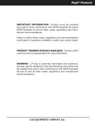
RegO ® <strong>Excess</strong> <strong>Flow</strong>, <strong>Check</strong>, <strong>Filler</strong>, & <strong>Vapor</strong> <strong>Equalizing</strong> <strong>Valves</strong>Double-<strong>Check</strong> <strong>Filler</strong> <strong>Valves</strong>General InformationRegO ® Double-<strong>Check</strong> <strong>Filler</strong> <strong>Valves</strong> incorporate a resilient upper checkvalve, normally designated as a filler valve, and a lower check valve,commonly called a back pressure check valve. Available in a range ofsizes to cover virtually all LP-Gas storage containers, these valves areUL listed and meet NFPA standards, as well as other safety requirements.<strong>Flow</strong> of liquid into the storage container opens both check valves.When flow stops, they both are designed to close automatically topermit the operator to disconnect the hose coupling. The automaticclosing action also helps prevent the discharge of container contentsin the event of hose failure. The lower back pressure check affordsextra protection by restricting the discharge if the upper check fails tofunction properly due to accidents or other causes.The double back check construction allows emergency inspection,repair, or replacement of the upper fill assembly without removingproduct from the container. When the upper filler valve body isremoved, the lower back check valve provides a seal, permitting onlysome leakage, allowing a new upper filler valve body to be installed.Seal cap made of tough, resilient moldedplastic. Protects threads and internalworking parts. Caps are designedto contain normal tank pressures, andmust be kept on valves at all times.Long-wearing gasket permits hand-tightconnection of cap and hose coupling.Safety groove is designed to shearbelow the ACME thread, leaving thevalve seats closed and unaffected if thedelivery truck pulls away with the hoseconnected.Seat disc of special synthetic compositionis extra thick for longer life.Valve guide is precision machined toassure positive seal.Exclusive swing-away lower back checkvalve for extra fast filling is provided onModels 6579 and 6587. Differs fromconventional design by swiveling to avertical position when opened.Double-<strong>Check</strong> <strong>Filler</strong> <strong>Valves</strong> for Large MotorFuel and ASME TanksDesigned to provide fast filling of large motor fuel and ASME domestictanks.The 6579 Series incorporates a swing-away lower check which greatlyreduces pressure drop across the valve. This lower pressure droppromotes faster filling rates and greater efficiency resulting in moreprofitable operations.<strong>Excess</strong> <strong>Flow</strong>,<strong>Check</strong>, <strong>Filler</strong> & <strong>Vapor</strong><strong>Equalizing</strong> <strong>Valves</strong>7579P75796579Part NumberTankACME HoseWrenchPropane Liquid Capacity at Various Differential Pressures (GPM)ConnectionCap Only Cap, Chain and RingConnectionHex FlatsM. NPT5 PSIG 10 PSIG 25 PSIG 50 PSIG 75 PSIG7579 7579C50 70 111 157 1927579P - 1¼” M.NPT37 52 82 116 1421¾”1 7 ⁄8”6579** 6579C** 78 110 174 246 3017579ZT 7579C 1¼” M.NPS*** 50 70 111 157 192* Incorporates ¾ F. NPT dip pipe connection** Swing-away lower back check valve design for higher filling rate. NOTE: Multiply flow rate by .94 to determine liquid butane capacity.*** National Pipe StraightSpare Gasket Ordering Information1¼” A2797-20R1¾” A2697-20R2¼” A3184-8R3¼” A3194-8R79
RegO ® <strong>Excess</strong> <strong>Flow</strong>, <strong>Check</strong>, <strong>Filler</strong>, & <strong>Vapor</strong> <strong>Equalizing</strong> <strong>Valves</strong>Double <strong>Check</strong> <strong>Filler</strong> <strong>Valves</strong> for Forklift, Motor Fuel and RV TanksDesigned to provide fast filling of forklift, motor fuel, and recreational vehicle tanks.UL®7647HF7647H7647SC7647DC7647SA<strong>Excess</strong> <strong>Flow</strong>,<strong>Check</strong>, <strong>Filler</strong> & <strong>Vapor</strong><strong>Equalizing</strong> <strong>Valves</strong>BasicPart Numberw/Lanyardand CapHoseConnectionTankConnectionM. NPT* Large 1¾” hex wrench flats.** 30˚ angle on 1¼” ACME hose connection.*** Multiply flow rate by .94 to determine liquid butane capacity.WrenchFlatsEffective Length(Approx.)7647H7647HF--½” F. NPT½” SAE Flare2 7 ⁄16”2 5 ⁄8”- 7647DC1¾” ACME & F.1½”¾”POL3”- 7647SA**3 1 ⁄16”1¾” ACME- 7647SC* 1¾” 2¼”*Double <strong>Check</strong> <strong>Filler</strong> <strong>Valves</strong> for Delivery TruckTanks and Large Storage ContainersDesigned to provide fast filling of bobtails, transports and large bulkstorage tanks.The 6587EC incorporates a swing-away lower check which greatlyreduces pressure drop across the valve. This lower pressure drop promotesfaster filling rates and greater efficiency resulting in more profitableoperations.UL®Propane Liquid Capacity at VariousDifferential Pressures (GPM)***10PSIG20PSIG30PSIG40PSIG50PSIG14 20 24 27 507579S 6587DC 3197C6588LEPart NumberACMEHoseConnectionTankConnectionM. NPTWrenchHex Flats* Swing-away lower back check valve design for higher filling rates.** 3125L Hydrostatic Relief Valve included.NOTE: Multiply flow rate by .94 to determine liquid butane capacity.EffectiveLength(Approx.)Propane Liquid Capacity at Various Differential Pressures (GPM)5 PSIG 10 PSIG 25 PSIG 50 PSIG 75 PSIG7579S 1¾” 1½” 2” 2 11 ⁄16” 44 62 98 139 1706587EC* 2¼“ 2” 2 7 ⁄8” 4 3 ⁄8” 92 130 206 291 3563197C 3¼” 3” 4” 6½” 148 210 332 470 5756588LE** 3¼” 2” 3”6589LE** 3¼” 3” 3¼”5 7 ⁄8” 138 223 349 NA NASingle <strong>Check</strong> <strong>Filler</strong> <strong>Valves</strong> for Storage Tanks withSupplementary Back <strong>Check</strong> <strong>Valves</strong>Designed for use with RegO® Back <strong>Check</strong> <strong>Valves</strong> to provide fast filling ofbulk storage tanks. Also may be used as a spare or replacement part.These single check filler valves must never be installed directly into containercouplings. They must be used with the appropriate back checkvalve to comply with NFPA Pamphlet #58.PartNumberACME HoseConnectionOutletConnectionM. NPTWrenchHex Flats* Stem Assembly designed for higher filling rates.NOTE: Multiply flow rate by .94 to determine liquid butane capacity.Propane Liquid Capacity at VariousDifferential Pressures (GPM)For Use WithBack <strong>Check</strong>Valve:5 PSIG 10 PSIG 25 PSIG 50 PSIG3174C 1¾” 1¼” 1¾” 23 33 52 74 31766584C* 2¼” 2” 2 3 ⁄8” 156 220 348 492 A31863194C 3¼” 3” 3½” 147 208 329 465 A31963174C3194C, 6584C80
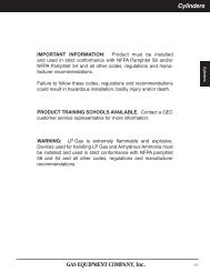
RegO ® <strong>Excess</strong> <strong>Flow</strong>, <strong>Check</strong>, <strong>Filler</strong>, & <strong>Vapor</strong> <strong>Equalizing</strong> <strong>Valves</strong><strong>Vapor</strong> <strong>Equalizing</strong> <strong>Valves</strong>General InformationRegO ® <strong>Vapor</strong> <strong>Equalizing</strong> <strong>Valves</strong> consist of an upper back check valveand lower excess flow valve. In the closed position, the attachment of avapor hose coupling with its projecting nozzle, opens the back checkvalve to permit flow in either direction. The lower excess flow valve isdesigned to close automatically when flow out of the container beingfilled exceeds the rated capacity. The valve closes automatically whenthe coupling is removed. Like the double-check filler valves, the vaporequalizing valves utilize a two-piece body construction. The lowerexcess flow valve will permit some leakage when the upper back checkvalve is removed for emergency repairs or replacement.Seal cap made of tough, resilient moldedplastic. Protects threads and internal workingparts. Caps are designed to contain normaltank pressures, and must be kept on valvesat all times.Long-wearing gasket permits hand-tightconnection of cap and hose coupling.Seat disc of special synthetic composition isextra thick for longer life.Valve guide is precision machined to assurepositive seal.RegO ® <strong>Vapor</strong> <strong>Equalizing</strong> <strong>Valves</strong> are designed for use in both ASMEand DOT containers.Double <strong>Check</strong> <strong>Vapor</strong> <strong>Equalizing</strong> <strong>Valves</strong> for ASME and DOT ContainersDesigned to facilitate loading operations by providing equalization ofpressures in the supply and storage containers. The supplementaryexcess flow valve closes when the flow from the container being filledexceeds a predetermined rate.The 7573 Series is designed for use in bulk delivery systems andmotor fuel containers. The 3183AC is designed for use in deliverytrucks and other large containers.BasicPart NumberWith Cap & ChainACME HoseConnectionTankConnectionM. NPTWrenchHexFlatsEffectiveLength(Approx.)Approx. Closing <strong>Flow</strong> at100 PSIG Inlet Pressure(SCFH/Propane)7573D 7573DC 1¼” ¾” 1¼” 2 1 ⁄16” 4,100- 3183AC 1¾” 1¼” 2” 3 1 ⁄16” 10,000UL®<strong>Excess</strong> <strong>Flow</strong>,<strong>Check</strong>, <strong>Filler</strong> & <strong>Vapor</strong><strong>Equalizing</strong> <strong>Valves</strong>Spare Gasket Ordering InformationACMEPart Number1¼” A2797-20R1¾” A2697-20RSingle <strong>Check</strong> <strong>Vapor</strong> <strong>Equalizing</strong> <strong>Valves</strong> for ASME and DOTContainers with Supplementary <strong>Excess</strong> <strong>Flow</strong> <strong>Valves</strong>Designed for use with RegO® <strong>Excess</strong> <strong>Flow</strong> <strong>Valves</strong> to facilitate loadingoperations by providing equalization of pressures in the supply andstorage containers. Also may be used as a spare or replacement part.These vapor equalizing valves must never be installed directly intocontainer couplings. They must be used with the appropriate excessflow valve to comply with NFPA Pamphlet #58.UL®BasicPart NumberWith Cap & ChainInletConnectionOutletConnectionWrench HexFlatsEffective Length(Approx.)Approximate Closing <strong>Flow</strong> at 100 PSIGInlet Pressure (SCFH/Propane <strong>Vapor</strong>)For Use With <strong>Excess</strong><strong>Flow</strong> Valve:3170 - 1¼” ¾” 1¼” 1 9 ⁄16” 7.600 3272E- 3180C 1¾” 1¼” 1¾” 1 11 ⁄16” 10,000 3282A81
RegO ® <strong>Excess</strong> <strong>Flow</strong>, <strong>Check</strong>, <strong>Filler</strong>, & <strong>Vapor</strong> <strong>Equalizing</strong> <strong>Valves</strong>Back Pressure <strong>Check</strong> <strong>Valves</strong>General InformationRegO ® Back Pressure <strong>Check</strong> <strong>Valves</strong> are designed to allow flow in onedirection only. The check, normally held in the closed position by aspring, precludes the possibility of flow out of the container. When flowstarts into the container, the pressure overcomes the force of the springto open the check. When the flow stops or reverses, the check closes.Metal-to-metal seats will allow slight leakage after closure. These valveswill restrict the escape of container contents in the event of accidentalbreakage of the piping or fittings.NEW 3” Soft Seat Back <strong>Check</strong> ValveDesigned to provide protection in a container opening when desiredflow is always into the container. May be used on in-line applicationswhere flow must be limited to one direction. Note: The 3” M-NPTconnections must be used for in-line service, the 2” outlet connectionis for a standpipe when installed inside of a container.UL®<strong>Excess</strong> <strong>Flow</strong>,<strong>Check</strong>, <strong>Filler</strong> & <strong>Vapor</strong><strong>Equalizing</strong> <strong>Valves</strong>PartNumberA3198SInletConnection3” Male & 2”FemaleOutletConnection3” Male & 2”FemaleWrenchHex FlatsEffectiveLength(Approx.)Back Pressure <strong>Valves</strong> for Container orLine ApplicationsPropane Liquid Capacity at VariousDifferential Pressures (GPM)5 PSIG 10 PSIG 25 PSIG3½” 3 7 ⁄8” 210 290 400Designed to provide protection of a container opening when desiredflow is always into the vessel. May be used in line applications whereflow must be limited to one direction.When used with the appropriate single check filler valve, the combinationforms a double check filler valve suitable for use in filling ofbulk storage tanks.UL®3146 Series, 3176 Series,A3186, A3196A3187SA3276BCPart NumberInlet OutletEffectivePropane Liquid Capacity at variousWrench HexConnection ConnectionLengthdifferential pressures (GPM)FlatsBrass Steel F. NPT M. NPT(approx.) 5 PSIG 10 PSIG 25 PSIG 50 PSIG3146 A31463⁄4” 3⁄4” 1 3 ⁄8” 1 15 ⁄16” 11 16 25 363146S* -3176 A31761 3 ⁄8” 28 40 63 891 1 ⁄4” 1 1 ⁄4” 2”- A3276BC* 2 1 ⁄2” 32 45 73 103- A3186 2” 2” 2 7 ⁄8” 2 7 ⁄16” 124 175 276 391- A3187S*2” M &1 1 ⁄4” F2” M &1 1 ⁄4” F2 3 ⁄8” 4 3 ⁄8” 60 110 225 350- A3196 3” 3” 4” 3 15 ⁄16” 297 420 664 939*Soft seat version.NOTE: Multiply flow rate by .94 to determine liquid butane capacity and by .90 to determine liquid anhydrous ammonia capacity.82
RegO ® <strong>Excess</strong> <strong>Flow</strong>, <strong>Check</strong>, <strong>Filler</strong>, & <strong>Vapor</strong> <strong>Equalizing</strong> <strong>Valves</strong>Swing-Away Back Pressure <strong>Check</strong> <strong>Valves</strong> forContainer or Line ApplicationsUL®Designed to provide protection of a container opening when desired flowis always into the vessel. May also be used in the line applications whereflow must be limited to one direction.When used with the appropriate single check filler valve, the combinationforms a double check filler valve suitable for use in filling of bulk storagetanks.The swing-away check offers more efficient flow rates than conventionaldesigns. It swivels open vertically to reduce pressure drop across thevalve and improves flow rates.Part Number Inlet Connection Outlet Connection Wrench Effective Length Propane Liquid Capacity at Various Differential Pressures (GPM)Brass Steel F. NPTM. NPT Hex Flats (Approx.) 5 PSIG 10 PSIG 25 PSIG 50 PSIG6586D A6586D 2” 2” 2 7 ⁄8” 2 7 ⁄16” 190 270 420 600NOTE: Multiply flow rate by .94 to determine liquid butane capacity.Back Pressure <strong>Check</strong> <strong>Valves</strong> for FlangedInstallationDesigned to provide high flow capacity and allow more efficient tank fillingthan conventional designs. The unobstructed throat area reduces flowturbulence through the valve, thereby reducing pressure drop. Large flowchannels and spacious side ports assure ample capacity for the mostdemanding high capacity filling operations.The valve is designed for installation in internally threaded flanges in containerbottoms.Part NumberFlange ConnectionM. NPTWrench HexFlatsOverall LengthThreaded EndTo PortUL®Propane Liquid Capacity at Various Differential Pressures(GPM)5 PSIG 10 PSIG 25 PSIG 50 PSIGA3400L4 2”5¼” 1 5 ⁄16” 223 316 500 707SlottedA3400L6 3” 5 9 ⁄32” 1 9 ⁄16” 424 600 949 1342<strong>Excess</strong> <strong>Flow</strong>,<strong>Check</strong>, <strong>Filler</strong> & <strong>Vapor</strong><strong>Equalizing</strong> <strong>Valves</strong>NOTE: For installation in flange tank connections with internal threads, see the “Flanged Installation in Container” section under “<strong>Excess</strong> <strong>Flow</strong> <strong>Valves</strong>.”Multiply flow rate by .94 to determine liquid butane capacity and by .90 for liquid anhydrous ammonia capacity.Sight <strong>Flow</strong> Indicators for Bulk PlantsDesigned to promote maximum pump efficiency, these indicators enable bulk plant operatorsto visually inspect liquid flow conditions. With glass on both sides of the indicator, flowcan be observed from either side, even under some poor light conditions. The integral swingcheck also serves as a back-check valve to prevent reverse flow and product loss if the hosefails in a loading operation.By installing an indicator on the upstream side of the plant pump, suction conditions can beobserved and the pump speed adjusted to obtain the maximum possible flow rate withoutcavitation. Additionally, if an indicator is installed in the piping at the loading rack, just aheadof the loading hose, the operator can maintain a constant check on pump conditions.Both installations are designed to allow for observation to provide maximum pump efficiencyand assure safe plant pump operation.In compressor operations a sight flow indicator installed in the liquid line will give a visualindication when the tank car or transport is emptied. Compressor operation can then beimmediately reversed to start recovery of the vapor.PartNumberInlet/OutletConnectionsLengthA7794 2" F. NPT 5 3 ⁄4"A7796 3" F. NPT 7 3 ⁄8"NOTE: For fixed pipe installations only83
RegO ® <strong>Excess</strong> <strong>Flow</strong>, <strong>Check</strong>, <strong>Filler</strong>, & <strong>Vapor</strong> <strong>Equalizing</strong> <strong>Valves</strong>Chek-Lok® Adhesive Warning LabelsThese adhesive warning labels are intended for application as close aspossible to the Chek-Lok® once the Chek-Lok® is installed.The basic information contained on the label is intended for the benefit ofthe user of the Chek-Lok® and is not intended to be an “all-inclusive” productwarning.This label is printed on a heavy duty material with pressure sensitive adhesivebacking. The ultra-violet ink stands up well when exposed to the environment.DANGERLP-GAS IS EXTREMELYFLAMMABLE AND EXPLOSIVEW ARNINGAVOID SERIOUS INJURY AND PROPERTY DAMAGE. IF YOU SEE, SMELL,OR HEAR ESCAPING GAS... EVACUATE AREA IMMEDIATELY! CALL YOURLOCAL FIRE DEPARTMENT! DO NOT ATTEMPT TO REPAIR. DO NOTSTORE IN BUILDING OR ENCLOSED AREA. DO NOT USE ON HOT AIRBALLOONS OR AIRCRAFT.CAUTION!Use this CHECK-LOK ® connection only for liquid evacuation before movingtank in accordance with NFPA Pamphlet 58, which is the law in many states.This publication is available from NFPA, Batterymarch Park, Quincy, MA02269. Read and follow ECII ® product instruction number 7572FA-301.DO NOT REMOVE, DEFACE OR OBLITERATE THIS LABEL.DO NOT FILL THIS CONTAINER UNLESS THIS LABEL IS READABLE.ADDITIONAL SAFETY INFORMATION IS AVAILABLE FROMPart NumberDescription7572-400 Adhesive Warning LabelPrinted in U.S.A. 03-0994-1189Part No. 7572-400100 RegO Drive PO Box 247 Elon College, NC 27244 USA Phone (336) 449-7707 F ax (336) 449-6594 www .regoproducts.c omWarning Notice<strong>Excess</strong> <strong>Flow</strong>,<strong>Check</strong>, <strong>Filler</strong> & <strong>Vapor</strong><strong>Equalizing</strong> <strong>Valves</strong>The following warning information, Part Number 903-500, is includedwith each shipment of <strong>Excess</strong> <strong>Flow</strong>, <strong>Check</strong>, <strong>Filler</strong> and <strong>Vapor</strong> <strong>Equalizing</strong><strong>Valves</strong> to the first purchaser of the product from the factory.This information is intended to be forwarded throughout the product distributionchain. Additional copies are available from REGO® andAuthorized Product Distributors.84