F-3100 Series Inline Electromagnetic Flow Meter Manual - Onicon
F-3100 Series Inline Electromagnetic Flow Meter Manual - Onicon
F-3100 Series Inline Electromagnetic Flow Meter Manual - Onicon
- No tags were found...

You also want an ePaper? Increase the reach of your titles
YUMPU automatically turns print PDFs into web optimized ePapers that Google loves.
F-<strong>3100</strong> SERIESIn-line <strong>Electromagnetic</strong> <strong>Flow</strong> <strong>Meter</strong>Installation & Basic Operation Guide0670-7 / 169581500 North Belcher Road, Clearwater, FL 33765 • Tel (727) 447-6140 • Fax (727) 442-5699www.onicon.com • sales@onicon.com01-13
1500 North Belcher Road, Clearwater, FL 33765 • Tel (727) 447-6140 • Fax (727) 442-5699 • sales@onicon.comF-<strong>3100</strong> <strong>Flow</strong> <strong>Meter</strong> <strong>Manual</strong> 01/13 - 0670-7 Page 2
SAFETY INFORMATIONThis meter was calibrated at the factory before shipment. To ensure correct use of the meter, pleaseread this manual thoroughly.Regarding this <strong>Manual</strong>:• This manual should be passed on to the end user.• Before use, read this manual thoroughly to comprehend its contents.• The contents of this manual may be changed without prior notice.• All rights reserved. No part of this manual may be reproduced in any form withoutONICON’s written permission.• ONICON makes no warranty of any kind with regard to this material, including, but notlimited to, implied warranties of merchantability and suitability for a particular purpose.• All reasonable effort has been made to ensure the accuracy of the contents of this manual.However, if any errors are found, please inform ONICON.• ONICON assumes no responsibilities for this product except as stated in the warranty.• If the customer or any third party is harmed by the use of this product, ONICON assumesno responsibility for any such harm owing to any defects in the product which were notpredictable, or for any indirect damages.Safety Precautions:The following general safety precautions must be observed during all phases of installation,operation, service, and repair of this product. Failure to comply with these precautions or withspecific WARNINGS given elsewhere in this manual violates safety standards of design,manufacture, and intended use of the product. ONICON Incorporated assumes no liability for thecustomer’s failure to comply with these requirements. If this product is used in a manner notspecified in this manual, the protection provided by this product may be impaired.The following symbols are used in this manual:!WARNINGMessages identified as “Warning” contain information regarding the personal safety of individualsinvolved in the installation, operation or service of this product.!CAUTIONMessages identified as “Caution” contain information regarding potential damage to the product orother ancillary products.iIMPORTANT NOTEMessages identified as “Important Note” contain information critical to the proper operation of theproduct.1500 North Belcher Road, Clearwater, FL 33765 • Tel (727) 447-6140 • Fax (727) 442-5699 • sales@onicon.comF-<strong>3100</strong> <strong>Flow</strong> <strong>Meter</strong> <strong>Manual</strong> 01/13 - 0670-7 Page 3
1500 North Belcher Road, Clearwater, FL 33765 • Tel (727) 447-6140 • Fax (727) 442-5699 • sales@onicon.comF-<strong>3100</strong> <strong>Flow</strong> <strong>Meter</strong> <strong>Manual</strong> 01/13 - 0670-7 Page 4
TABLE OF CONTENTS1.0 INTRODUCTION ..................................................................................................71.1 Purpose Of This Guide.............................................................................. 71.2 Principle Of Operation.............................................................................. 71.3 Typical <strong>Flow</strong> <strong>Meter</strong> Installation ................................................................71.4 Standard Features And Specifications...................................................... 81.5 Additional Hardware That May Be Required............................................91.5.1 Grounding Rings...........................................................................91.5.2 Gaskets........................................................................................101.6 Working Environment .............................................................................101.7 Warranty And Serial Number .................................................................102.0 UNPACKING .....................................................................................................112.1 Checking That You Have Received Everything...................................... 113.0 INSTALLATION.................................................................................................. 123.1 Site Selection ...........................................................................................123.1.1 General Guidelines.....................................................................133.1.2 <strong>Flow</strong> Direction............................................................................133.1.3 Remote Mount Transmitter........................................................133.1.4 Minimum Straight Run Requirements.......................................143.2 Mechanical Installation ...........................................................................153.2.1 Standard Transmitter Dimensions.............................................153.2.2 Sensor Body Dimensions & Weights..........................................163.2.3 Installation Drawing For Conductive Pipe................................193.2.4 Installation Drawing For Non Conductive Pipe........................213.2.5 Installation Drawing For Threaded Connections..................... 223.2.6 Installation Instructions ........................................................... 233.2.7 Torque Specifications ................................................................253.2.8 Remote Mount Transmitter........................................................263.3 Electrical Installation ...............................................................................273.3.1 Input Power Requirements.........................................................273.3.2 Power And Output Signal Wiring Instructions.........................273.3.3 Earth Connection........................................................................303.3.4 Remote Mount Cable Wiring Instructions.................................311500 North Belcher Road, Clearwater, FL 33765 • Tel (727) 447-6140 • Fax (727) 442-5699 • sales@onicon.comF-<strong>3100</strong> <strong>Flow</strong> <strong>Meter</strong> <strong>Manual</strong> 01/13 - 0670-7 Page 5
TABLE OF CONTENTS (CONTINUED)4.0 F-<strong>3100</strong> START-UP AND COMMISSIONING .....................................................324.1 Display And Keypad Operation...............................................................334.2 Helpful Hints For Start-Up And Commissioning ...................................344.3 Start-Up And Commissioning..................................................................344.4 Start-Up And Commissioning Worksheet................................................354.5 Troubleshooting Guide.............................................................................354.6 Alarm Interpretation And Standard Led’s...............................................36APPENDIXA-1 FIELD REMOTE MOUNTING THE TRANSMITTER .......................................38A-2 CONDITIONS OF SALE.....................................................................................411500 North Belcher Road, Clearwater, FL 33765 • Tel (727) 447-6140 • Fax (727) 442-5699 • sales@onicon.comF-<strong>3100</strong> <strong>Flow</strong> <strong>Meter</strong> <strong>Manual</strong> 01/13 - 0670-7 Page 6
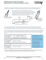
SECTION 1.0: INTRODUCTION1.1 PURPOSE OF THIS GUIDEThe purpose of this guide is to provide installation and commissioning procedures and basicoperating instructions for the F-<strong>3100</strong> In-line <strong>Electromagnetic</strong> <strong>Flow</strong> <strong>Meter</strong>.1.2 PRINCIPLE OF OPERATIONThe operating principles of ONICON F-<strong>3100</strong> In-line <strong>Electromagnetic</strong> <strong>Flow</strong> <strong>Meter</strong>s are basedon Faraday’s Law of <strong>Electromagnetic</strong> Induction. Faraday’s Law states that a voltage will beinduced in a conductor (water or other conductive liquid) when it passes through a magnetic field(generated by the meter), and the induced voltage will be directly proportional to the velocity ofthe conductor. By placing electrodes on opposite sides of the flow tube, it is possible to accuratelymeasure the induced voltage and determine the corresponding velocity of the flowing liquid.!WARNINGOnly qualified service personnel should attempt to install or service this product. Serious injurymay result from the improper installation or use of this product.1.3 TYPICAL FLOW METER INSTALLATIONONICON’S F-<strong>3100</strong> <strong>Series</strong> In-line Magnetic <strong>Flow</strong> <strong>Meter</strong>s are suitable for volumetric flowmeasurement F-3000 of <strong>Series</strong> electrically Mating conductive Flange liquids Grounding a wide variety Kit of Instructionsapplications includingbi-directional applications.INSTALLATION IN STEEL (CONDUCTIVE) PIPE<strong>Flow</strong> direction1500 Note North 1. Belcher Road, Clearwater, FL 33765 • Tel (727) 447-6140 • Fax (727) 442-5699 • sales@onicon.comF-<strong>3100</strong> Using a <strong>Flow</strong> #21 <strong>Meter</strong> (0.159”) <strong>Manual</strong> drill bit, 01/13 drill a - 0670-7 ½” deep hole in edge of each mating flange. Tap each hole using a 10-32 Page tap. 7Secure the provided ring connectors and grounding wires to the flanges using the provided green grounding screws.(Alternate method: Weld 10-32 studs (not provided) to the flange faces and attach ring connectors with 10-32 nuts (not pro
1.4 STANDARD FEATURES AND SPECIFICATIONSA built-in user interface & displayA single 4 – 20 mA output for flow rateTwo programmable open collector pulse outputs. Outputs may be programmed to provide:* an indication of flow direction* a scaled pulse for totalizing flow* a high resolution frequency output to drive peripheral devices* an indication of an alarm conditionEmpty pipe detectorInternal self-diagnostic functions & fault alarmsCALIBRATION<strong>Flow</strong> meters are wet calibrated in a flow laboratoryagainst standards that are directly traceable togovernment standards. A certificate of calibrationaccompanies every meter.ACCURACY± 0.4% of reading from 3.3 to 33 ft/sec± 0.8% of reading from 1 to 3.3 ft/sec± 0.0075 ft/s at flows less than 1 ft/sPROGRAMMINGFactory programmed for specific application<strong>Flow</strong> Tube (Internal):304 Stainless SteelConnection Type:Standard: ANSI 150 Class FlangeOptional: ANSI 300 Class FlangeOptional: WaferOptional: Threaded Process ConnectionELECTRICALThis equipment is intended for INSTALLATIONCATEGORY (OVERVOLTAGE CATEGORY) IIapplications.MEMORYNonvolatile memory retains all program parametersand totalized values in the event of power loss.DISPLAYAlphanumeric LCD displays total flow, flow rate,flow direction & alarm conditionsOUTPUT SIGNALSIsolated 4 – 20 mA analog output for flow rateTwo programmable open collector pulse outputs(configurable for frequency, pulse or directionalflow)TEMPERATURE RANGELiquid temperature range:Polypropylene liner: 32° to 140°FEbonite liner: 23° to 175°FPTFE liner: -4° to 212° F (266° F with remoteelectronics)Ambient temperature range: 14° to 122°FMAINTENANCEPeriodically inspect the power supply cables,cable glands and the enclosure for signs of damage.Inspect installation and mounting hardware forloose connections.MECHANICALElectronics Enclosure:Standard: Nylon NEMA 4Optional: Remote mount transmitter version,maximum distance from the sensor is 65ft.Outer Body Material:Standard: Carbon Steel, PaintedOptional: 316 Stainless SteelInput Power - Factory Selectable:Standard - 90 to 265 VAC, 45 to 66 Hz, and 35 mAmaximumOptional - 10 to 63 VDC, 15 to 45 VAC, 45 to66 Hz and 300 mA maximumOvercurrent Protective Device Ratings:Supply mains overcurrent protective deviceswith the following ratings:• 120 VAC 50/60 Hz – 15 A• 230 VAC 50 Hz – 6 AWiring:<strong>Flow</strong> signals - Use 18-22 AWG shielded cableStandard input power - Use a three wire servicewith one wire a protective earth ground. Theinstallation must comply with all local, stateand federal building codes.Optional input power - Use PVC jacketed coppercable with a wire gauge suitable for the lengthof run and required maximum current carryingcapacity. The installation must comply with alllocal, state and federal building codes.PRESSURE AND CONDUCTIVITYMaximum Operating Pressure(Exclusive of flange rating)Ebonite: 1000PSIPolypropylene: 230PSIPTFE: 580PSIMinimum Fluid Conductivity:5 microsiemens/centimeterNote: Specifications are subject to change without notice.1500 North Belcher Road, Clearwater, FL 33765 • Tel (727) 447-6140 • Fax (727) 442-5699 • sales@onicon.comF-<strong>3100</strong> <strong>Flow</strong> <strong>Meter</strong> <strong>Manual</strong> 01/13 - 0670-7 Page 8
1.5 ADDITIONAL HARDWARE THAT MAY BE REQUIRED1.5.1 Grounding RingsGrounding rings may be required whenever meters are installed in non-metallic or linedpipes. Grounding rings placed before and after the meter eliminates electrical noise thatwill interfere with the proper operation of the meter. ONICON provides grounding ringsas an optional accessory. Grounding ring dimensional information and part numbers arelisted below. For proper operation, grounding rings are required before and after the meter.5/83/8D1/4CBore1/8”AGrounding Ring Dimensions & ONICON Part NumbersNominalSizeBore A C D T 316 SS Part#1” 1 - 1/16 2 - 5/8 4 - 9/16 1 - 15/16 1/8 152121.5” 1 – 9/16 3 – 3/8 5 - 5/16 1 - 15/16 1/8 152132” 2 – 1/16 4 – 1/8 6 - 1/16 1 - 15/16 1/8 152143” 3 – 1/16 5 – 3/8 7 - 5/16 1 - 15/16 1/8 152154” 4 – 1/16 6 – 7/8 8 - 13/16 1 - 15/16 1/8 152166” 6 8 – 3/4 10 - 11/16 1 - 15/16 1/8 152178” 8 11 12 - 15/16 1 - 15/16 1/8 1521810” 9 – 1/2 13 – 3/8 15 - 5/8 2 - 1/4 1/8 1521912” 11 – 9/16 16 – 1/8 18 - 9/16 2 - 7/16 1/8 1522014” 13 – 1/2 17 – 3/4 20 - 3/8 2 - 5/8 1/8 1522116” 15 – 1/4 20 – 1/4 22 - 7/8 2 - 5/8 1/8 1522218” 17 – 3/8 21 – 5/8 24 - 1/4 2 - 5/8 1/8 1522320” 19 23 - 7/8 26 - 11/16 2 - 13/16 1/8 1522424” 23 28 – 1/4 31 - 1/8 2 - 7/8 1/8 1522530” 29 34 – 3/4 38 3 - 1/2 1/8 1522636” 35 41 – 1/4 45 - 1/4 4 1/8 1522742” 41 48 52 - 1/2 4 - 1/2 1/8 152281500 North Belcher Road, Clearwater, FL 33765 • Tel (727) 447-6140 • Fax (727) 442-5699 • sales@onicon.comF-<strong>3100</strong> <strong>Flow</strong> <strong>Meter</strong> <strong>Manual</strong> 01/13 - 0670-7 Page 9
1.5.2 GasketsGaskets are required for sensor bodies with ebonite and polypropylene liners and arestrongly recommended for meters with PTFE liners. Gasket dimensions must comply withASME B16.5 flange standards. ONICON is not a gasket manufacturer and does not supplygaskets for this product.The following general suggestions are provided to assist the installer in choosing theproper gasket material. In all cases, the responsibility of selecting the appropriate materialrests with the installer.Gaskets are used to create a seal between the flow meter liner surface and the surfaceof the mating flange. The proper choice of gasket material will allow for a leak freeconnection at the time of installation and maintain that seal over time. How well thegasket works depends on a number of factors. Each of these should be considered whenchoosing a gasket material.• Is it chemically compatible with the fluid?• Will it withstand the expected minimum and maximum operating temperatures?• Does it provide enough resiliency and creep resistance to maintain loading over time?• Will it deform enough to create a seal by filling imperfections in the sealing surfaces?• Is it thick enough to take up variations in flatness of the surface?In many cases a simple 1/8” red rubber gasket with a Shore A hardness (Durometer) of60 – 80 will suffice. Your local gasket supplier should be able to guide you in selecting thebest material for your application.1.6 WORKING ENVIRONMENTThe F-<strong>3100</strong> was designed for installation and use in typical industrial environments that are freeof corrosive liquids and fumes, direct liquid exposure, direct sunlight, temperature extremes andvibrations.The operating ambient air temperature range is -4° F to 140° F.The electrical power should be relatively clean, free of high frequency noise, large voltagetransients, and protected from power surges and brown outs.1.7 WARRANTY & SERIAL NUMBERWarrantyONICON’s complete warranty is included in Appendix A of this manual as part of the“Conditions of Sale”. ONICON provides a two-year warranty.Serial NumberThe F-<strong>3100</strong> has 2 separate serial numbers. The transmitter serial number is located on theidentification plate located on the electronics enclosure. The sensor serial number is located onthe identification plate located on the sensor body.1500 North Belcher Road, Clearwater, FL 33765 • Tel (727) 447-6140 • Fax (727) 442-5699 • sales@onicon.comF-<strong>3100</strong> <strong>Flow</strong> <strong>Meter</strong> <strong>Manual</strong> 01/13 - 0670-7 Page 10
SECTION 2.0: UNPACKINGThe F-<strong>3100</strong> is generally shipped in one package unless optional hardware or equipment is ordered.Notify the freight carrier (all products are shipped insured) and ONICON’s Customer ServiceDepartment if any items are damaged in transit.2.1 CHECKING THAT YOU HAVE RECEIVED EVERYTHING• Standard DocumentationEnclosed with each F-<strong>3100</strong> is a comprehensive documentation package that includes thefollowing items:Certificate of CalibrationThe F-<strong>3100</strong> Installation and Operation GuidePlease notify ONICON if any of these items are missing.F-<strong>3100</strong> SERIESIn-line <strong>Electromagnetic</strong> <strong>Flow</strong> <strong>Meter</strong>Installation & Basic Operation Guide0670-11500 North Belcher Road, Clearwater, FL 33765 • Tel (727) 447-6140 • Fax (727) 442-5699www.onicon.com • sales@onicon.com03-11FLOW METERCERTIFICATE OF CALIBRATIONCALIBRATION & CONFIGURATION DATA for F-3000 SERIES MAGNETIC FLOW METERSMETER DATACALIBRATION of PRIMARY FLOW ELEMENT<strong>Meter</strong> Tag: CT-WH Ka factor:-1.0951Model:F-3103-111Medium:WaterSerial Number: 220177Component S/N's: 04N1420 38M6901Primary Calibration Date: 4/12/2011<strong>Meter</strong> Size: 3"Max. Operating Pressure:225 psiMax. Operating Temperature: 212 °FConnections: ANSI 150# Class FlangesPeripheral device serial number 220177This meter was manufactured for ONICON Incorporated.The original manufacturer certifies that this flow meter wascalibrated against standards that are traceable toSIT, Italy.FACTORY PROGRAMMED OUTPUT SIGNALS(Performed at ONICON Factory; can be reprogrammed in the field)Analog <strong>Flow</strong> Range: 4-20 mA = 0 to230 Gal/MinFull Scale Frequency Output: 200.00 HzScaled Pulse Output: 1 100 Gallonspulse =Programmed By:GLDate: 5/25/20111500 N Belcher Road, Clearwater, Florida 33765 Tel (727)447-6140 Fax (727)442-56991500 North Belcher Road, Clearwater, FL 33765 • Tel (727) 447-6140 • Fax (727) 442-5699 • sales@onicon.comF-<strong>3100</strong> <strong>Flow</strong> <strong>Meter</strong> <strong>Manual</strong> 01/13 - 0670-7 Page 11
• Integral Mount TransmitterF-<strong>3100</strong> In-line <strong>Electromagnetic</strong> <strong>Flow</strong> <strong>Meter</strong>s with integrally mounted transmitters areshipped fully assembled. Remove the meter from the shipping carton and inspect it forphysical damage.• Remote Mount TransmitterF-<strong>3100</strong> In-line <strong>Electromagnetic</strong> <strong>Flow</strong> <strong>Meter</strong>s ordered with the remote transmittermounting option will be shipped in one carton that contains the flow sensor body, thetransmitter with mounting hardware and the necessary cable to connect the two together.Remove each and inspect it for physical damage.iIMPORTANT NOTEF-<strong>3100</strong> transmitters and sensor bodies are two parts of one uniquely calibrated system and mustbe installed together. Mixing components from other systems will result in significant calibrationerrors.• Grounding RingsGrounding rings are optional accessories that may be required for proper installation.Grounding rings may be shipped in a separate carton. Remove each and inspect it forphysical damage.SECTION 3.0: INSTALLATIONThe F-<strong>3100</strong> In-line <strong>Electromagnetic</strong> <strong>Flow</strong> <strong>Meter</strong> should be installed by experienced plumbers,electricians and others with related knowledge and experience in the heating, cooling, and fluidmetering fields. ONICON will be happy to assist with technical recommendations and to provideguidance by telephone and/or email. On-site field engineering, installation and service are alsoavailable at an additional cost.The installer should use good trade practices and must adhere to all state and local building or otherapplicable codes.3.1 SITE SELECTIONCareful attention during the site selection process will help the installers with the initialinstallation, reduce start-up problems, and make future maintenance easier. For example, do notinstall the flow meter where it will be difficult for personnel to perform periodic maintenance.When selecting a site for mounting, consider the criteria under Section 1.6, WORKINGENVIRONMENT, as well as the following:iIMPORTANT NOTEProper site selection is critical to the performance of this flow meter. The flow meter must beproperly located within the piping system in order to ensure an accurate flow measurement.1500 North Belcher Road, Clearwater, FL 33765 • Tel (727) 447-6140 • Fax (727) 442-5699 • sales@onicon.comF-<strong>3100</strong> <strong>Flow</strong> <strong>Meter</strong> <strong>Manual</strong> 01/13 - 0670-7 Page 12
3.1.1 General GuidelinesWhen properly installed, the flow meter will only measure flow associated with thatportion of the piping system for which the flow measurement is being made. Choose thelocation with the longest straight unobstructed run of pipe, keeping in mind that in someapplications it may be possible to locate the meter in either the supply or return pipe.3.1.2 <strong>Flow</strong> DirectionF-<strong>3100</strong> flow meters are inherently bi-directional and changes in flow direction areindicated by a change in polarity of the sensing signal. In order for the meter to displaythe correct polarity, it is necessary to orient the meter relative to flow direction duringthe installation process. The sign of the flow rate is positive when the flow direction isfrom – to + as printed on the tag plate as shown below. Prior to installation, determine thedirection of flow in the piping system and orient the meter accordingly.-FLOW DIRECTION+iIMPORTANT NOTE<strong>Flow</strong> direction is indicated by polarity symbols (+/-) and flow totals are accumulated separatelybased on direction. The polarity of the flow indication may be reversed by reversing the polarity ofthe Ka coefficient.3.1.3 Remote Mounted TransmitterFind an easily accessible location where wire connections can be made and meter readingscan be taken from floor level. Mount the transmitter on a vibration free surface. Avoidlocations that contain electric motors or other strong sources of electrical interference.iIMPORTANT NOTEThe F-<strong>3100</strong> remote mounted transmitter option is provided without a pre-amplifier. As a result,the maximum distance it can be located away from the sensor body is limited to 65ft. A remotetransmitter option with a pre-amplifier is available with the F-3200 advanced transmitter. With thismodel the remote transmitter may be located up to 1640ft away from the sensor body.Contact ONICON if you need to locate the remote transmitter more than 65ft from the sensor body.1500 North Belcher Road, Clearwater, FL 33765 • Tel (727) 447-6140 • Fax (727) 442-5699 • sales@onicon.comF-<strong>3100</strong> <strong>Flow</strong> <strong>Meter</strong> <strong>Manual</strong> 01/13 - 0670-7 Page 13
3.1.4 Minimum Straight Run RequirementsThe straight run requirements presented below represent the minimum requirementsfor accurate flow measurement. For optimum performance, provide as much additionalstraight run as possible.iIMPORTANT NOTEFor proper operation, install the flow meter in a straight run of pipe free of bends, tees, valves,transitions and obstructions for a distance of at least 3 diameters upstream and 2 diametersdownstream.Recommended InstallationAvoid these installationsPlace flow meter at least 3pipe diameters upstreamand 2 pipe diametersdownstream from bendsand obstrutions.3 DIA 2 DIA3 DIA 2 DIAAvoid downward flowwhich can lead to partiallyfilled pipes.3 DIA 2 DIAElectrode locationThe electrodes shouldbe located in thehorizontal axis (3 o’clockand 9 o’clock) in order toprevent sediment fromsettling on them.Electrode locationElectrode Location1500 North Belcher Road, Clearwater, FL 33765 • Tel (727) 447-6140 • Fax (727) 442-5699 • sales@onicon.comF-<strong>3100</strong> <strong>Flow</strong> <strong>Meter</strong> <strong>Manual</strong> 01/13 - 0670-7 Page 14
3.2 MECHANICAL INSTALLATIONiIMPORTANT NOTEF-<strong>3100</strong> transmitters and sensor bodies are two parts of one uniquely calibrated system and mustbe installed together. Mixing components from other systems will result in significant calibrationerrors.3.2.1 Standard Transmitter DimensionsNet weight 1.6 lbs3”2.5”Install sensorcable here0.25” Diameter1500 North Belcher Road, Clearwater, FL 33765 • Tel (727) 447-6140 • Fax (727) 442-5699 • sales@onicon.comF-<strong>3100</strong> <strong>Flow</strong> <strong>Meter</strong> <strong>Manual</strong> 01/13 - 0670-7 Page 15
3.2.2 Sensor Dimensions & WeightsAnsi Class 150 Flanged Sensor Overall DimensionHDLShown with 4-bolt patternSensor SizeNominal Diameter 1” 1.25” 1.5” 2” 2.5” 3” 4” 5” 6” 8” 10” 12”Lenght (L above) 7.87 7.87 7.87 7.87 7.87 7.87 9.84 9.84 11.81 13.78 17.72 19.68Height (H above) 7.13 7.55 8.15 8.74 9.64 10.20 11.34 12.40 13.43 15.79 18.15 20.75Flange Dia (D above) 4.24 46.4 5.00 5.98 7.00 7.52 9.02 10.00 10.98 13.50 15.98 19.02Weight in lbs 6.6 9.7 11 15.4 21.5 26.4 32.0 35.2 55 75 138 159Sensor SizeNominal Diameter 14” 16” 18” 20” 24” 26” 30” 34” 36” 42” 48”Length (L above) 21.65 23.62 23.62 23.62 23.62 25.59 29.53 33.46 35.43 39.37 47.24Height (H above) 22.91 25.16 27.08 29.57 34.09 36.26 40.63 45.24 47.48 54.37 58.66Flange Dia (D above) 20.98 23.50 25.00 27.52 32.01 34.25 38.74 43.74 45.98 52.99 57.28Weight in lbs 238 341 407 462 664 770 911 1210 1386 1716 19481500 North Belcher Road, Clearwater, FL 33765 • Tel (727) 447-6140 • Fax (727) 442-5699 • sales@onicon.comF-<strong>3100</strong> <strong>Flow</strong> <strong>Meter</strong> <strong>Manual</strong> 01/13 - 0670-7 Page 16
Wafer Style Sensor Overall DimensionsG0.95"HDLI.D.Sensor SizeNominal Dia 1” 1.25” 1.5” 2” 2.5” 3” 4” 5” 6” 8” 10” 12” 14” 16”L 3.94 3.94 3.94 3.94 5.90 5.90 5.90 7.09 7.09 7.87 9.84 11.81 13.78 15.75H 5.79 6.02 6.34 6.97 7.83 8.23 9.25 10.35 11.46 14.25 16.42 18.39 20.75 22.80D 2.20 2.44 2.76 3.39 4.25 4.65 5.67 6.77 7.87 10.67 12.83 14.80 17.17 19.21G - - - - - - - - - 5.67 7.64 9.60 11.57 13.54Net Weight in lbs 2.6 3.5 4.0 4.4 7.9 8.4 11 17.2 18 40 53 59 70 86Threaded VersionHPolypropylene Stainless SteelWeight 4.85 lbs 4.85 lbsL 5.5” 4.72”H 7.4” 6.69”W 3.8” 3.07”LW1500 North Belcher Road, Clearwater, FL 33765 • Tel (727) 447-6140 • Fax (727) 442-5699 • sales@onicon.comF-<strong>3100</strong> <strong>Flow</strong> <strong>Meter</strong> <strong>Manual</strong> 01/13 - 0670-7 Page 17
Recommended method for lifting all sensors with eyeboltsThe eyebolts aredesigned to hold onlythe weight of the meter!WARNINGEyebolts are provided to assist in the safe installation of meters with a nominal diameter greaterthan 6 inches. The eyebolts are only designed to hold the weight of the meter. Do not attempt toplace an additional load on the eyebolts during installation.1500 North Belcher Road, Clearwater, FL 33765 • Tel (727) 447-6140 • Fax (727) 442-5699 • sales@onicon.comF-<strong>3100</strong> <strong>Flow</strong> <strong>Meter</strong> <strong>Manual</strong> 01/13 - 0670-7 Page 18
F-3000 <strong>Series</strong> Mating Flange Grounding Kit Instructions3.2.3 Installation Drawings for Conductive PipeNote 2.INSTALLATION IN STEEL (CONDUCTIVE) PIPE<strong>Flow</strong> directionNote 1. Note 1.Note 3.Note 1.1 2 " deep hole in edge of each mating flange. Tap each holeusing a 10-32 tap. Secure the ring connectors (provided) and grounding wires to the flange uthe green grounding screws (provided).(Alternate (Alternate method method: : Weld 10-32 studs (not (not provided) to the to flange the flange faces and faces attach and ring attach ringconnectors with with 10-32 10-32 nuts (not provided).Note 1. Using a #21 (0.159”) drill bit, drill ½” deep hole in edge of each mating flange. Tap eachUsing hole a # using 21 (0.159") a 10-32 tap. drill Secure bit, drill the a ring connectors (provided) and grounding wires to the flangeusing the green grounding screws (provided).Note 2. Provide a ground connection at the input power terminals inside the transmitter enclosure.Note 2.Provide a ground connection at the input power terminals inside the transmitter enclosure.Note 3. Provide a quality earth ground connection to the meter.Note From 3. best to worst, grounding options include:Provide a 1. quality Earth grounding earth ground rod driven connection into the to soil. the meter.From best 2. to Earth worst, wire grounding connected directly options to include: the building electrical service panel.1. Earth grounding3. Earth wirerodconnectiondriven intoinsidetheansoil.electrical outlet mear the meter.2. Earth wire connected directly to the building electrical service panel.3. Earth wire connection inside an electrical outlet near the meter.CAUTION!The earth connections must be made as shown. Failure to do so will result in erratic operation ofthe meter.1500 North Belcher Road, Clearwater, FL 33765 • Tel (727) 447-6140 • Fax (727) 442-5699 • sales@onicon.comF-<strong>3100</strong> <strong>Flow</strong> <strong>Meter</strong> <strong>Manual</strong> 01/13 - 0670-7 Page 19
(Wafer Style <strong>Meter</strong>)Note 3.INSTALLATION IN CONDUCTIVE PIPENote 2.<strong>Flow</strong> directionNote 1.Note 1.Note 4.Note 1. Using a #21 (0.159”) drill bit, drill a ½” deep hole in edge of each mating flange. Tap eachhole using a 10-32 tap. Secure the ring connectors (provided) and grounding wires to the flangeusing the green grounding screws (provided).(Alternate method: Weld 10-32 studs (not provided) to the flange faces and attach ringconnectors with 10-32 nuts (not provided).Note 2. Note For 2. meters provided with a grounding electrode connect grounding wire to terminal on themeter neck as shown.Note 3. Provide a ground connection at the input power terminals inside the transmitter enclosure.Note 4. From best to worst, grounding options include:1. Earth grounding rod driven into the soil.2. Earth wire connected directly to the building electrical service panel.Note 4.3. Earth wire connection inside an electrical outlet mear the meter.!Note 1.Using a # 21 (0.159") drill bit, drill1a2 " deep hole in edge of each mating flange. Tap eachhole using a 10-32 tap. Secure the ring connectors (provided) and grounding wires to theflange using the green grounding screws (provided).(Alternate method : Weld 10-32 studs (not provided) to the flange faces and attach ringconnectors with 10-32 nuts (not provided).For meters provided with a grounding electrode connect grounding wire to terminal on themeter neck as shown.Note 3.Provide a ground connection at the input power terminals inside the transmitter enclosure.From best to worst, grounding options include:1. Earth grounding rod driven into the soil.2. Earth wire connected directly to the building electrical service panel.CAUTION3. Earth wire connection inside an electrical outlet near the meter.The earth connections must be made as shown. Failure to do so will result in erratic operation ofthe meter.1500 North Belcher Road, Clearwater, FL 33765 • Tel (727) 447-6140 • Fax (727) 442-5699 • sales@onicon.comF-<strong>3100</strong> <strong>Flow</strong> <strong>Meter</strong> <strong>Manual</strong> 01/13 - 0670-7 Page 20
3.2.4 Installation Drawing for Non-Conductive PipeINSTALLATION IN NON CONDUCTIVE PIPE(EXPLODED VIEW)GASKET (4PL)<strong>Flow</strong> DirectionGROUNDING RING (2PL)1500 North Belcher Road, Clearwater, FL 33765 • Tel (727) 447-6140 • Fax (727) 442-5699 • sales@onicon.comF-<strong>3100</strong> <strong>Flow</strong> <strong>Meter</strong> <strong>Manual</strong> 01/13 - 0670-7 Page 21
WAFER INSTALLATION INNON-CONDUCTIVE PIPEGASKETGROUNDING RINGGASKET<strong>Flow</strong> Direction!CAUTIONThe earth connections must be made as shown. Failure to do so will result in erratic operation of themeter.3.2.5 Installation Drawing for Threaded Connections!CAUTIONThe earth connections must be made as shown. Failure to do so will result in erratic operation ofthe meter.1500 North Belcher Road, Clearwater, FL 33765 • Tel (727) 447-6140 • Fax (727) 442-5699 • sales@onicon.comF-<strong>3100</strong> <strong>Flow</strong> <strong>Meter</strong> <strong>Manual</strong> 01/13 - 0670-7 Page 22
3.2.6 Installation Instructions!WARNINGInstallation of this product should only be attempted by qualified tradespersons and must complywith all local, state and federal building codes.1. Thoroughly clean all flange surfaces removing all traces of any old gasket material orany adhesive residue.2. Inspect all flange surfaces for warping, pitting or other surface imperfections that mayprevent a good seal.3. Use new bolts, nuts and hardened washers. ONICON recommends the use of B7 nuts,bolts and washers. Prior to installation, lubricate the bolt threads, nuts, washer facesand the underside of the bolt head with lubricant (Fel Pro C5A or equivalent). Thislubricant is necessary to ensure uniform stress distribution on the sealing surface. Usecare not to get any lubricant on the liner or gasket material.4. Center the new gasket on the liner surface. Do not allow the gasket to protrude into theflow stream.5. Use the torque specifications shown below to determine the recommended final bolttorque requirements.6. Using a torque wrench, tighten the bolts in at least three stages (30%, 60% & 100%)using a repeating pattern sequence shown in the diagrams below.ANSI Class 150 Flange Bolt Tightening SequenceLiner material1500 North Belcher Road, Clearwater, FL 33765 • Tel (727) 447-6140 • Fax (727) 442-5699 • sales@onicon.comF-<strong>3100</strong> <strong>Flow</strong> <strong>Meter</strong> <strong>Manual</strong> 01/13 - 0670-7 Page 23
ANSI Class 150 Flange Bolt Tightening Sequence1500 North Belcher Road, Clearwater, FL 33765 • Tel (727) 447-6140 • Fax (727) 442-5699 • sales@onicon.comF-<strong>3100</strong> <strong>Flow</strong> <strong>Meter</strong> <strong>Manual</strong> 01/13 - 0670-7 Page 24
3.2.7 Torque SpecificationsTighten uniformly in a diagonal sequence as per the table below. Contact ONICON fortorque specifications for meters with a nominal diameter larger than 24 inches.Torque Specifications in ft-lbOperating PressurePSI 140 260 350 600 1000Dia. PTFE EBON PTFE EBON PP PTFE EBON PTFE EBON EBON1” 19 14 19 19 291.25” 32 21 32 32 401.5” 40 27 40 40 542” 51 39 51 51 602.5” 67 56 34 34 633” 40 31 40 40 464” 44 42 62 62 655” 57 53 83 83 1106” 80 79 100 100 1618” 110 91 73 61 99 83 132 110 17210” 91 76 104 87 151 126 197 165 23712” 105 88 130 108 149 124 205 172 23414” 127 106 152 127 239 200 312 260 35516” 161 134 208 174 315 262 457 381 46018” 144 119 208 17320” 166 138 282 23524” 239 199 419 3501500 North Belcher Road, Clearwater, FL 33765 • Tel (727) 447-6140 • Fax (727) 442-5699 • sales@onicon.comF-<strong>3100</strong> <strong>Flow</strong> <strong>Meter</strong> <strong>Manual</strong> 01/13 - 0670-7 Page 25
3.2.8 Remote Mount TransmitterRemote mount transmitters are provided with a single “L” bracket with two ¼” mountingholes. The bracket is secured to the transmitter by means of a large bolt with a knurledknob for a head. To mount the bracket, first separate it from the transmitter housing andattach it to the wall or other vertical surface. Cable from the sensor body is attached to thetransmitter using the center strain relief.Mounting BracketCable is suppliedalready attached tothe sensor body.Cable wires arelabeled with numberswhich correspond toconnection terminalson the transmitter.!CAUTIONDO NOT drill holes in the transmitter. Use only the openings that are provided. DO NOT cut theremote cable. Coil excess cable at one end.3”2.5”1”0.25” DIAInsert2.5”Install sensorcable here0.25” Diameter1500 North Belcher Road, Clearwater, FL 33765 • Tel (727) 447-6140 • Fax (727) 442-5699 • sales@onicon.comF-<strong>3100</strong> <strong>Flow</strong> <strong>Meter</strong> <strong>Manual</strong> 01/13 - 0670-7 Page 26
3.3 ELECTRICAL INSTALLATION3.3.1 Input Power RequirementsF-3000 <strong>Electromagnetic</strong> <strong>Flow</strong> <strong>Meter</strong>s equipped with standard transmitters are availablewith two different options for input power. This is not a user selectable function and mustbe configured at the factory.Special care is required to ensure that the F-<strong>3100</strong> is properly connected to earth throughan earth wire. This connection is required to prevent random electrical noise frominterfering with the operation of the meter. (See section 3.3.3 for details.)* Low Voltage: 10 – 63 VDC, 15 – 45 VAC 45/66 Hz, 300 mA maximum* High Voltage (Mains): 90 – 265 VAC 45/66 Hz, 35 mA maximumiIMPORTANT NOTEThis option is not field selectable. Contact the factory if you need to change the input voltagerating.!CAUTION/WARNINGThis product must be connected to earth ground for proper operation. Failure to do so will result inerratic operation and an increased risk of injury.!WARNINGAll mains voltage connections must be made through pre-drilled conduit/strain relief openinglocated at the bottom of the enclosure. Failure to do so will result in an increased risk of injury.3.3.2 Power and Output Signal Wiring InstructionsFactory Default Output ConfigurationsONICON pre-programs the analog and pulse outputs based on application specific dataprovided at the time the meter is ordered. The table below shows how the pulse outputsare configured based on whether the application has bi-directional flow and if the meterwill be connected to an ONICON peripheral device such as an ONICON Btu meter ordisplay module.In all applications the analog 4-20 mA output is available at terminals 9 (+) and 10 (-).Application Pulse Output #1Terminals: 16 (+) & 17 (-)Pulse Output #2Terminals: 18 (+) & 19 (-)Standard Frequency Scaled PulseBi-directional *Scaled Output <strong>Flow</strong> Direction* This output will be configured for frequency if the flow meter is provided with a peripheral device.1500 North Belcher Road, Clearwater, FL 33765 • Tel (727) 447-6140 • Fax (727) 442-5699 • sales@onicon.comF-<strong>3100</strong> <strong>Flow</strong> <strong>Meter</strong> <strong>Manual</strong> 01/13 - 0670-7 Page 27
Step 1: Loosen screws to lift cover.Step 2: Lift cover to expose electrical connections.Step 3: Make SIGNAL connections as shownPull straight out on connectors to remove them.SIGNAL CONNECTIONSStep 4: Open cover to expose POWER Connections.POWER CONNECTIONS4-20 mA OutputPin 9 - Pos (+)Pin 10 - Neg (-)Pulse Out 2Pin 18 - Pos (+)Pin 19 - Neg (-)Pulse Out 1Pin 16 - Pos (+)Pin 17 - Neg (-)Remove retaining screw toexpose connector.(Shown with High Voltage)Power connectionsare under this cover.Pulse Output 1 / Pulse Output 2Opto-coupled open collector pulse outputsMaximum voltage: 40VDCMaximum current: 100mAMaximum saturation voltage collector/emitter @ 100mA: 3 VDC05165-15-081500 North Belcher Road, Clearwater, FL 33765 • Tel (727) 447-6140 • Fax (727) 442-5699 • sales@onicon.comF-<strong>3100</strong> <strong>Flow</strong> <strong>Meter</strong> <strong>Manual</strong> 01/13 - 0670-7 Page 28
POWER CONNECTIONS CONTINUEDStep 5:Pull straight out on theconnector to remove it.Low voltageversionHigh voltageversionStep 6:Wire the connector as shown based on inputtype. Earth connection must be made._L+NStep 7:Use the right hand strainrelief for installing the powercable or power conduit.3-13-081500 North Belcher Road, Clearwater, FL 33765 • Tel (727) 447-6140 • Fax (727) 442-5699 • sales@onicon.comF-<strong>3100</strong> <strong>Flow</strong> <strong>Meter</strong> <strong>Manual</strong> 01/13 - 0670-7 Page 29
3.3.3 Earth ConnectionF-<strong>3100</strong> <strong>Electromagnetic</strong> <strong>Flow</strong> <strong>Meter</strong>s are designed to detect microvolt signal levels at theelectrodes located in the flow meter body. These signals are generated as conductive fluids flowthrough the magnetic field generated by the meter. If enough random electrical noise is present atthe electrodes, it can interfere with the flow measurement. Care must be taken during installationto minimize the effects of electrical noise on the flow meter.The most effective way to minimize the effects of electrical noise is to make sure that the pipe,fluid, flow meter body and flow meter transmitter are all connected to the same earth ground.This accomplishes two important goals. First, it ensures that the pipe, fluid, flow meter bodyand electronics are all at the same electrical potential, and second, it ensures that this electricalpotential is the same as earth ground.In order to be certain that the meter is properly connected to earth, the flow meter body earthconnections (at the flanges or on the neck of wafer meters) and the transmitter earth connectionshould be run directly to a known earth connection. The length of this earth cable should be asshort as practically possible, preferably ≤25 feet in length. The table below lists earth connectionsfrom best to worst.iIMPORTANT NOTENon-metallic pipes are more susceptible to electrical noise. Grounding rings installed upstreamand downstream of the flow meter body to reduce the electrical noise present in the pipe may berequired for proper operation.!CAUTIONDo not use bolts that hold pressure to make earth connections. Using flange bolts may result in poorelectrical connections due to the presence of paint and/or lubricants. Use the dedicated flange earthconnections or the dedicated earth connection on the neck of wafer style meters.BestWorstEarth Connections (stranded wire 14 - 18 AWG)Earth grounding rod driven into the ground.Earth wire connected directly to the building electrical service panel.Earth wire connection inside an electrical outlet near the meter.1500 North Belcher Road, Clearwater, FL 33765 • Tel (727) 447-6140 • Fax (727) 442-5699 • sales@onicon.comF-<strong>3100</strong> <strong>Flow</strong> <strong>Meter</strong> <strong>Manual</strong> 01/13 - 0670-7 Page 30
SECTION 4.0: METER START UP & COMMISSIONINGFOR ONICON F-<strong>3100</strong> SERIES FLOW METERS1500 North Belcher Road, Clearwater, FL 33765 • Tel (727) 447-6140 • Fax (727) 442-5699 • sales@onicon.comF-<strong>3100</strong> <strong>Flow</strong> <strong>Meter</strong> <strong>Manual</strong> 01/13 - 0670-7 Page 32
4.1 DISPLAY AND USER INTERFACEThe F-<strong>3100</strong> standard transmitter is equipped with a 2 line by 16 character LCD with 0.2” highcharacters. Three pushbutton switches located inside the transmitter enclosure are used to changethe displayed data and program the meter functions.Momentarily press the UP (top) button to view alarmmessages.Momentarily press the RIGHT (middle) button to advanceto the next menu page.The ENTER (bottom) button is used in programming.<strong>Flow</strong> Rate<strong>Flow</strong> Direction IndicatorPercentage of Full ScaleEngineering UnitsPartial Positive <strong>Flow</strong> Total<strong>Flow</strong> RatePartial Positive <strong>Flow</strong> TotalTotal Positive <strong>Flow</strong> TotalTotal Negative <strong>Flow</strong> TotalPartial Negative <strong>Flow</strong> TotalPositive <strong>Flow</strong> TotalNegative flow Total<strong>Flow</strong> Rate<strong>Flow</strong> Velocity<strong>Flow</strong> RatePartial Negative <strong>Flow</strong> TotalWhen selected, this page will cause the menu pagesto scroll automatically.= = = = = = = >< = = = = = = =1500 North Belcher Road, Clearwater, FL 33765 • Tel (727) 447-6140 • Fax (727) 442-5699 • sales@onicon.comF-<strong>3100</strong> <strong>Flow</strong> <strong>Meter</strong> <strong>Manual</strong> 01/13 - 0670-7 Page 33
4.2 HELPFUL HINTS FOR START-UP AND COMMISSIONINGA step-by-step procedure and companion worksheet are located on the next two pages. Pleaseread all installation instructions and these helpful hints carefully before proceeding withinstallation, start-up and commissioning.1. ONICON flow meters are individually calibrated for a particular application. Be sure toverify the pipe size and location.2. The electronic sensing system will not work in air. The pipe must be full for properoperation.3. When measuring analog output signals, remember that currents (mA) must bemeasured in series, while voltages are measured in parallel. If the 4-20 mA signal isalready connected to a control system, you must break the connection and measure thesignal in series.4. When measuring frequency outputs in hertz, take your multimeter out of “autorangemode” and manually set range for a voltage level above 15 VDC. This will prevent falsereadings when signal is not present.5. Never connect power to analog or frequency output signal wires. ONICON F-<strong>3100</strong> <strong>Flow</strong><strong>Meter</strong>s are not “loop powered” devices.4.3 START-UP AND COMMISSIONINGPlease read the entire procedure carefully before proceeding. Wiring instructions are located onpages 21 - 24 of this manual. A worksheet for checking off the following steps and recordingmeasured values is located on the next page.1. Confirm flow meter location andadequate straight pipe run to achievedesired results.Is the meter located in the correct location as required by the plans?Compare actual straight pipe upstream and downstream of the meter location torecommended distances identified in this manual.2. Confirm control system programming. Confirm that the control system input point is properly configured for the analog range(or scale factor) identified on the calibration certificate.3. Confirm connection to correctONICON display or Btu meter (ifordered).Confirm that the flow meter serial number matches the ONICON display or Btu meterserial number (when ordered together).4. Verify wiring before connecting power. Prior to connecting the power, verify that the wiring is correct as shown in this manual and/or the additional wiring diagram provided with ONICON display or Btu meter. If in doubt,contact ONICON for assistance before proceeding further.5. Verify that the input voltage availableto power the meter is appropriate forthe meter version. (Check label insideLow voltage: 10 - 63 VDC or 15 - 45 VAC 45/66 Hz, 300 mA maximumHigh voltage: 90 - 265 VAC 45/66 Hz, 35 mA maximumtransmitter enclosure LV=Low voltage,HV=High voltage.6. Connect power. Wait approximately 45 seconds after power-on before proceeding further.The following steps require flow in the pipe. <strong>Flow</strong> signal readings should be taken while holding the flow rateconstant if possible. Otherwise, take the various output readings as quickly as possible.7. Measure and record analog or binaryoutputs.Current Output:Scaled Output:8. Compare various output signals toeach other and to the flow ratedisplayed and to the control system.Refer to flow meter wiring diagram for the various outputs available based on your particularflow meter model. Use the following formulas to calculate flow rate from measured analogsignals:GPM = (measured current in mA - 4) X Full Scale Analog <strong>Flow</strong> Rate16Each contact closure = unit volume identified as “Scale Factor” (measure and record timeinterval between contact closures)Compare the flow rates calculated in STEP 7 to the flow rate indicated by the display and thecontrol system. Refer to troubleshooting guide when readings are inconsistent.1500 North Belcher Road, Clearwater, FL 33765 • Tel (727) 447-6140 • Fax (727) 442-5699 • sales@onicon.comF-<strong>3100</strong> <strong>Flow</strong> <strong>Meter</strong> <strong>Manual</strong> 01/13 - 0670-7 Page 34
4.4 START-UP AND COMMISSIONING WORKSHEETPlease read all installation instructions carefully prior to proceeding with these steps. Use thefollowing worksheet for checking off the commissioning steps and recording measured values.STEP TEST/MEASUREMENT S/N: _________ S/N: ________ S/N: ________ S/N: _________1. <strong>Meter</strong> location:2. Control system programming:3. Match display or Btu meterserial # (S/N) if ordered:4. Signal connections verified:5. Supply voltage verified:6. Connect power:The following steps require flow in the pipe. <strong>Flow</strong> signal readings should be taken while holdingthe flow rate constant if possible. Otherwise, take the various output readings as quickly as possible.10. Analog or binary outputs4-20 mA signal: ________ mA ________ mA ________ mA ________ mAscaled output interval ___________ ___________ ___________ ___________Calculated flow rate: _______ GPM _______ GPM _______ GPM _______ GPM11 <strong>Flow</strong> rates displayed onmeter display: _______ GPM _______ GPM _______ GPM _______ GPMcontrol system: _______ GPM _______ GPM _______ GPM _______ GPM4.5 TROUBLESHOOTING GUIDENOTE: Also refer to the START-UP AND COMMISSIONING GUIDE located on the preceedingpages.REPORTED PROBLEMNo signalReading is too high or lowAnalog signal seems high orlow and does not correspondto frequency outputControl system displaysflow rate, but no flow rate isindicated on the localdisplay module or Btu meterPOSSIBLE SOLUTIONS• Verify correct wiring to control system (See wiring diagram.)• Check display for alarm messages. Verify that the pipe is full.• Verify that the sensor body and transmitter are both connected to earth ground.• Verify correct wiring to control system (see wiring diagram).• Confirm that the output signals are consistent (frequency vs. analog, etc).• Confirm that the control system is programmed for correct flow range or scale factor.Check for ground loop or offset voltage:• Verify that the sensor body and transmitter are both connected to earth ground.• Disconnect analog signal input from control system and measure analog outputs directly fromthe flow meter.• Re-connect signal input to control system and measure the analog signals again.• Any difference between these readings indicates a potential ground loop or offset voltage.• Please contact ONICON for further assistance.• Verify that all of the wires from the flow meter are connected to the display module or Btumeter.• The frequency output wire (green) must be connected for any ONICON display or Btu meter.1500 North Belcher Road, Clearwater, FL 33765 • Tel (727) 447-6140 • Fax (727) 442-5699 • sales@onicon.comF-<strong>3100</strong> <strong>Flow</strong> <strong>Meter</strong> <strong>Manual</strong> 01/13 - 0670-7 Page 35
4.6 ALARM INTERPRETATION AND STATUS LED’sALARMSALARMSAlarm IndicatorsSymbolDescriptionMWhen activated, this symbol indicates flow in excessof the set point.Range: 0-125% of full scalemINTERPRETATION When activated, ALARMS this symbol indicates flow below theALARM set point. DESCRIPTIONMRange:Alarm max0-125%activatedof full scalem Alarm min activated! • Open - Interruption coil connectioncoils circuit! • Signal - Segnal error• When - Empty activated, pipe indicates empty pipe.C Calibration runningCS Calibration Simulation runningSTransmitter Pulse output saturation in simulated (reduce output modeTIME PULSE )WPulse output saturated (change pulse rate orduration)LED1 2 3 4 5 6 7 8 9 1011 12 13 14 15 16 17 18 19 20Continuously ON: Initialization of firmwarePERMANENT LIGHT: initialisationFlashing LED: (1 second rate): Normal operationStatus LEDLED INTERPRETATIONFLASHING LIGHT ( 1 sec.): normal functionFlashing LED: (
APPENDIXA-1 FIELD REMOTE MOUNTING THE TRANSMITTERA-2 CONDITIONS OF SALE1500 North Belcher Road, Clearwater, FL 33765 • Tel (727) 447-6140 • Fax (727) 442-5699 • sales@onicon.comF-<strong>3100</strong> <strong>Flow</strong> <strong>Meter</strong> <strong>Manual</strong> 01/13 - 0670-7 Page 37
Field Remote Mounting the TransmitterWiring InstructionsSection 1: Removing the TransmitterBefore attempting to remote mount the transmitter, disconnect power at the source.Step 1Open cover. Slidecover off to the right,if desired.Step 2Open compartmentto expose powerconnection.Step 3Remove powerconnector from itssocket. Remove wiresfrom the connectorand set aside.Step 4Remove electrodeand coil connectorsfrom their sockets.Step 5Remove electrode and coil wiresfrom connectors and set aside.Step 6Remove mounting screws fromthe bottom of the enclosure.Screws do not need to be fullyremoved.Step 7Carefully separate the electronicsenclosure from the sensor body.As the two come apart, feed thesensor wires through the openingin the bottom of the enclosure.1500 North Belcher Road, Clearwater, FL 33765 • Tel (727) 447-6140 • Fax (727) 442-5699 • sales@onicon.comF-<strong>3100</strong> <strong>Flow</strong> <strong>Meter</strong> <strong>Manual</strong> 01/13 - 0670-7 Page 38
Section 2: Installing the Remote Mount Junction BoxStep 1Remove the cover andcircuit board from theremote mount junctionbox.Step 2Feed the cales throughthe holes in the bottomof the junction boxand mount it in place.Step 3Re-install the circuitboard.Step 4Attach the cables tothe terminal blocksas shown.(Note: Each wire is labeled witha number that corresponds to aterminal location.)Step 5Install the remotemount cable throughthe strain reliefsupplied with thejunction box.Step 6Install the remotemount cable to thenumbered terminalblock positions.Step 7Cables shouldbe connectedas shown.SensorcablesStep 8Re-install thecover.Remotetransmittercable1500 North Belcher Road, Clearwater, FL 33765 • Tel (727) 447-6140 • Fax (727) 442-5699 • sales@onicon.comF-<strong>3100</strong> <strong>Flow</strong> <strong>Meter</strong> <strong>Manual</strong> 01/13 - 0670-7 Page 39
Section 3: Wiring the TransmitterStep 1Remove the retainingnut and black plasticplug from the centerstrain relief on theenclosure and feed thenut over the end of thecable. Then feed thecable through the strainrelief.Step 2Attach the greenconnectors to theend of the cable.Numbers on eachwire correspond tothe numbers on theconnectors.Step 3Re-install theconnectors and tightenthe strain relief.Re-install the powercable and connector.Step 4Remove the o-ringfrom the remotemount bracket andplace it into the glandon the bottom of theenclosure as shown.Step 5Attach the mountingbracket using thescrews and lockwashers suppliedin the kit.Step 6Close and fastenthe cover.iIMPORTANT NOTETransmitter programming must be changed to complete the remote mount installation.1500 North Belcher Road, Clearwater, FL 33765 • Tel (727) 447-6140 • Fax (727) 442-5699 • sales@onicon.comF-<strong>3100</strong> <strong>Flow</strong> <strong>Meter</strong> <strong>Manual</strong> 01/13 - 0670-7 Page 40
CONDITIONS OF SALE1. ACCEPTANCE: The following Conditions of Sale apply to all sales of ONICON’s products. These provisions shall apply evenif ONICON fails to object to provisions appearing on, incorporated by, referenced in, or attached to Buyer’s purchase orderform. Buyer’s acceptance of delivery of ONICON’s products constitutes its acceptance of these Conditions of Sale.2. DELIVERY AND TITLE: All product shipments are F.O.B. shipping point and title passes to the Buyer at the time ONICONdelivers the merchandise to the carrier. Risk of loss or damage to the product passes to the Buyer at the time ONICON deliversthe product to the carrier. The Buyer immediately upon receipt should inspect all shipments, and should there be any evidence ofdamage or loss in transit, Buyer must file claims or tracers upon carrier. ONICON will assist in tracing shipments upon request.3. LIMITED WARRANTY: ONICON warrants that for a period of two (2) years following the date of original shipment of anONICON product: (i) the product will conform to ONICON’s standard written specifications applicable to such product in effecton the date of Buyer’s order, or as modified by ONICON’s quotation or Buyer’s purchase order accepted by ONICON, (ii) theproduct will be free from defects in workmanship, and (iii) that ONICON has title to the product prior to shipment to the Buyer;provided, however, that the warranties provided herein shall be void and may not apply in the event Buyer misuses ordamages a product, including, but not limited to, any use by the Buyer of a product for an application other than one of a typeapproved by ONICON. ONICON’s sole liability and Buyer’s sole remedy for any breach of the foregoing warranty is forONICON to repair or replace, at ONICON’s option, any defective product that is returned to ONICON during the warrantyperiod. EXCEPT AS MAY BE SPECIFICALLY AGREED BY ONICON IN WRITING IN RELATION TO EACH SALE, NOOTHER WARRANTIES SHALL APPLY, WHETHER EXPRESSED, IMPLIED OR STATUTORY, AND THERE SHALL BE NOIMPLIED WARRANTIES OF MERCHANTABILITY AND FITNESS FOR A PARTICULAR PURPOSE.4. REMEDIES: ONICON’s OBLIGATION UNDER THE FOREGOING WARRANTIES IS LIMITED SOLELY TO REPAIR ORREPLACEMENT, AT ONICON’s OPTION, OF DEFECTIVE OR NONCONFORMING PRODUCTS. ONICON SHALL NOT BELIABLE FOR CONSEQUENTIAL, INDIRECT, PUNITIVE, INCIDENTAL, OR SPECIAL DAMAGES WHETHER FOUND ONCONTRACT, TORT OR ANY OTHER THEORY OF LAW. No products shall be returned to ONICON without its prior consentand transportation and insurance costs shall be prepaid. Any repair or replacement of ONICON’s products under the foregoingwarranty will be at no charge to the Buyer provided such repair is done at the ONICON factory or authorized service center.ONICON products that are repaired or replaced under this warranty will be returned to Buyer via the same method of shipmentuse to return the product to ONICON. Repair or replacement of ONICON products is conditioned upon ONICON’sacknowledgement of any alleged defect or nonconformance during the warranty period and issuance of a ReturnAuthorization number. All product returns must reference the Return Authorization number on the outside of the shippingcarton and on any paperwork referencing the return.5. PRICES AND PAYMENT TERMS: The prices set forth in the most recent quote or acknowledgement as applicable, supersedeall previous prices or quotations. All quotations are subject to change or withdrawal without notice except as may be specificallynoted on the face of the quotation. The prices shown do not include sales, excise or government charges payable by ONICON toFederal, State, or local authority. Any such tax or charge now or hereafter imposed upon the sale or shipment of the productsunder this contract will be added to the purchase price. Buyer agrees to reimburse ONICON for such tax or charge or provideONICON with an acceptable exemption certificate. Payment of invoices will be due 30 days from the date of shipment of theproducts contained therein. In the event that payment of an invoice is not received by the invoice due date, ONICON will assessa late fee not to exceed 1.5% per month or 18% per year, or the maximum allowableby law whichever is lower.6. CANCELLATION: Buyer may cancel its order, or any part of it, by sending written notice of cancellation to ONICON andpaying a reasonable cancellation fee as determined by ONICON. The reasonable cancellation fee will reflect, among otherfactors, the expenses already incurred and commitments made by ONICON, sales and administrative costs and profit asdetermined by ONICON. If Buyer received a reduced price based on the quantity of products ordered, but has not purchasedthe applicable quantity at the time of cancellation, Buyer will pay the price it would have paid had ONICON’s sale price beenbased on the quantity actually purchased.7. CHANGES: If Buyer makes any changes in its drawings, designs, or specifications applicable in any contract with ONICONthat cause an increase or decrease in the cost of performance of the contract, or if such changes result in rework or obsolescence, anequitable adjustment shall be made to the contract. Such changes are subject to ONICON’s prior written consent.8. EXCUSABLE DELAY: ONICON shall under no circumstance be responsible for failure to fill any order or orders when due to: fires,floods, riots, strikes, freight embargoes or transportation delays, shortage of labor, inability to secure fuel, material supplies, or powerat current price or on account of shortages thereof, acts of God or of the public enemy, any existing or future laws or acts of theFederal or State Government (including specifically, but not exclusively, and orders, rules or regulations issued by any official oragency of any such government) affecting the conduct of ONICON’s business with which ONICON in its judgment and discretiondeems it advisable to comply as a legal or patriotic duty, or due to any cause beyond ONICON’s reasonable control.9. PATENTS: ONICON shall defend all suits or proceedings brought against Buyer or its customers arising from claimedinfringements of any patent, trademark, service mark or copyright for any product furnished by ONICON and shall indemnify itagainst all costs, fees, and damages on the condition Buyer promptly notifies ONICON in writing and provides information andassistance to enable ONICON to conduct the defense, provided that ONICON shall have no such obligation in case ofinfringement resulting from ONICON’s conformance to special requirements of Buyer. If ONICON is not able to settle any suchsuit or proceeding on acceptable terms, ONICON may, at its option, require return of the infringing product and refund thepurchase price to Buyer less a reasonable allowance for depreciation or use.10. FAIR LABOR STANDARDS ACT: ONICON represents that all products delivered under this contract are furnished inaccordance with the applicable provisions of the Fair Labor Standards Act as amended.11. APPLICABLE LAW: This document and any resulting contract shall be governed by and construed in accordance with thelaws of the State of Florida. The courts of the State of Florida and the federal courts located in Florida shall have jurisdictionand venue with respect to litigation to this contract. In the event of litigation, the prevailing party shall be entitled to recoverattorney’s fees and costs from the non-prevailing party, including appellate attorney’s fees.12. MODIFICATIONS: These Conditions of Sale along with the prices, quantities, delivery schedules and other provisions andinstructions in applicable quotations by ONICON or Buyer’s purchase orders accepted by ONICON shall constitute the entireagreement between ONICON and Buyer pertaining to any resulting contract. They can be modified only in writing.1500 North Belcher Road, Clearwater, FL 33765 • Tel (727) 447-6140 • Fax (727) 442-5699 • sales@onicon.comF-<strong>3100</strong> <strong>Flow</strong> <strong>Meter</strong> <strong>Manual</strong> 01/13 - 0670-7 Page 41