F-2500 Series Vortex Flow Meter Installation and Operation ... - Onicon
F-2500 Series Vortex Flow Meter Installation and Operation ... - Onicon
F-2500 Series Vortex Flow Meter Installation and Operation ... - Onicon

Create successful ePaper yourself
Turn your PDF publications into a flip-book with our unique Google optimized e-Paper software.
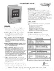
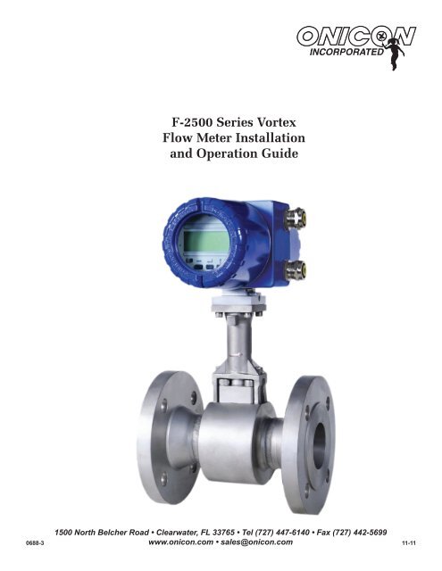
F-<strong>2500</strong> <strong>Series</strong> <strong>Vortex</strong><strong>Flow</strong> <strong>Meter</strong> <strong>Installation</strong><strong>and</strong> <strong>Operation</strong> GuideFor software version CF 4.7 <strong>and</strong> higher0688-31500 North Belcher Road • Clearwater, FL 33765 • Tel (727) 447-6140 • Fax (727) 442-5699www.onicon.com • sales@onicon.com 11-11
SAFETY INFORMATIONThis meter was calibrated at the factory before shipment. To ensure correct use of the meter, please read thismanual thoroughly.Regarding this Manual:• This manual should be passed on to the end user.• Before use, read this manual thoroughly to comprehend its contents.• The contents of this manual may be changed without prior notice.• All rights reserved. No part of this manual may be reproduced in any form withoutONICON’s written permission.• ONICON makes no warranty of any kind with regard to this material, including, but notlimited to, implied warranties of merchantability <strong>and</strong> suitability for a particular purpose.• All reasonable effort has been made to ensure the accuracy of the contents of this manual.However, if any errors are found, please inform ONICON.• ONICON assumes no responsibilities for this product except as stated in the warranty.• If the customer or any third party is harmed by the use of this product, ONICON assumes noresponsibility for any such harm owing to any defects in the product which were notpredictable, or for any indirect damages.Safety Precautions:The following general safety precautions must be observed during all phases of installation,operation, service, <strong>and</strong> repair of this product. Failure to comply with these precautions or withspecific WARNINGS given elsewhere in this manual violates safety st<strong>and</strong>ards of design, manufacture,<strong>and</strong> intended use of the product. ONICON Incorporated assumes no liability for the customer’sfailure to comply with these requirements. If this product is used in a manner not specified in thismanual, the protection provided by this product may be impaired.The following symbols are used in this manual:!WARNINGMessages identified as WARNING contain information regarding the personal safety of individualsinvolved in the istallation, operation or service of theis product.!CAUTIONMessages identified as CAUTION contain information regarding the potential damage to the productor other ancillary products.iIMPORTANT NOTICEMessages identified as IMPORTANT NOTICE contain information critical to the proper operation ofthe product.1500 North Belcher Road, Clearwater, FL 33765 • Tel (727) 447-6140 • Fax (727) 442-5699 • sales@onicon.comF-<strong>2500</strong> <strong>Flow</strong> <strong>Meter</strong> Manual 11/11 - 0688-3 Page 2
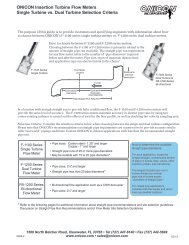
SECTION 1.0: INTRODUCTIONWe, at ONICON INCORPORATED, would like to thank you for purchasing our F-<strong>2500</strong> <strong>Series</strong> <strong>Vortex</strong><strong>Flow</strong> <strong>Meter</strong>. As our valued customer, our commitment to you is to provide fast reliable service <strong>and</strong>assistance, while continuing to offer you new products to meet your growing flow measurement needs.1.1 PURPOSE OF THIS GUIDEThe purpose of this guide is to provide installation <strong>and</strong> commissioning procedures <strong>and</strong> basicoperating <strong>and</strong> servicing instructions for ONICON F-<strong>2500</strong> <strong>Series</strong> <strong>Vortex</strong> <strong>Flow</strong> <strong>Meter</strong>s.!WARNINGOnly qualified service personnel should attempt to install or service this equipment. Serious injurymay result from the improper installation or use of this equipment.1.2 PRINCIPAL OF OPERATIONONICON F-<strong>2500</strong> vortex flow meters utilize Karman’s vortex street principle to detect changesin velocity in the medium flowing around a bluff body contained within the meter body. Avolumetric flow rate is then derived by utilizing the known cross-sectional area of the meter body<strong>and</strong> the average velocity of the medium. A built-in temperature sensor <strong>and</strong> an optional pressuresensor provide the compensation necessary for direct mass flow measurement of saturated orsuperheated steam, liquids <strong>and</strong> a variety of industrial gases.1.3 TYPICAL FLOW METER INSTALLATIONONICON’s F-<strong>2500</strong> In-line <strong>Vortex</strong> <strong>Flow</strong> <strong>Meter</strong>s are suitable for volumetric <strong>and</strong> mass flowmeasurement of air, gases, liquids or steam in a wide variety of applications.Output signals tocontrol system2-wire connectionfor flow rate2-wire connectionfor totalizationInsulation1-earth wire1500 North Belcher Road, Clearwater, FL 33765 • Tel (727) 447-6140 • Fax (727) 442-5699 • sales@onicon.comF-<strong>2500</strong> <strong>Flow</strong> <strong>Meter</strong> Manual 11/11 - 0688-3 Page 4
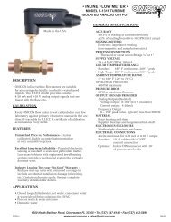
1.4 FEATURES AND SPECIFICATIONS• Mass flow measurement of saturated steam using built-in temperature compensation<strong>Flow</strong> rate, flow total <strong>and</strong> operating temperature are displayed. A 4 – 20mA output for flowrate <strong>and</strong> a scaled pulse output for flow total are available.• Volumetric flow measurement of liquids<strong>Flow</strong> rate, flow total <strong>and</strong> operating temperature are displayed. A 4 – 20mA output for flowrate <strong>and</strong> a scaled pulse output for flow total are available.• St<strong>and</strong>ard volumetric flow measurement of air or gases using built-in temperaturecompensation <strong>and</strong> optional pressure compensation<strong>Flow</strong> rate, flow total, operating temperature <strong>and</strong> operating pressure are displayed. A4 – 20mA output for flow rate <strong>and</strong> a scaled pulse output for flow total are available.• Mass flow measurement of superheated steam using built-in temperature compensation <strong>and</strong>optional pressure compensation<strong>Flow</strong> rate, flow total, operating temperature <strong>and</strong> operating pressure are displayed. A4 – 20mA output for flow rate <strong>and</strong> a scaled pulse output for flow total are available.• Hart FSK serial communications is available with all versions.GENERAL SPECIFICATIONSDisplayElectronics Enclosure<strong>Flow</strong>DirectionArrowSensor BodyMountingFlange1500 North Belcher Road, Clearwater, FL 33765 • Tel (727) 447-6140 • Fax (727) 442-5699 • sales@onicon.comF-<strong>2500</strong> <strong>Flow</strong> <strong>Meter</strong> Manual 11/11 - 0688-3 Page 5
CALIBRATIONEach meter undergoes a 5 point velocity calibration from0-250 ft/secACCURACYSteam & Gases:Accurate to within ± 1.5% of reading (Mass)Steam & Gases:Accurate to within ± 1.0% of reading (Volumetric)Liquids:Accurate to within ± 0.75% of reading (Volumetric)Re ≥ 20,000Repeatability:± 0.1%Long term stability:± 0.1% over a period of 1 yearPROGRAMMINGEach meter is programmed at the factory based onapplication specific data provided by the customer. <strong>Meter</strong>is field re-programmable via keypad, with coded access forsecurity.MEMORYNonvolatile EEPROM memory retains all programparameters <strong>and</strong> totalized values in the event of power loss.DISPLAY2 line, 10 character alphanumeric LCD(Optional) Remote mount transmitter version available;includes a fixed length 32 ft cable. The cable lengthcannot be altered.Note: meters provided with integral pressure compensationcannot use the remote mount transmitter option.OUTPUT SIGNALSRate: 2-wire, 4 – 20mA, 14 – 36 VDC, Maximum resistance:R ≥ ((Vsupply – 14V) / 22mA)Totalization: 2-wire, Scaled pulse, 0.5Hz, 30VDC & 100mAmaximumDigital: Hart, FSKNETWORK INTERFACEHART – FSKTEMPERATURE RANGEAmbient temperature range: -40°F (-40°C) to +85°F (+85°C)Medium temperature range: -40°F (-40°C) to +464°F (+240°C)MAINTENANCEPeriodically inspect the cable gl<strong>and</strong>s <strong>and</strong> the enclosurefor signs of damage. Inspect installation hardware for looseconnections.MECHANICALElectronics Enclosure:St<strong>and</strong>ard: Intefral epoxy painted aluminum, NEMA 6Optional: Remote mount enclosure with fixed 32 ft cable(Note: cable length cannot be altered.)CONNECTION TYPESt<strong>and</strong>ard: ½” – 3” (DN15 – DN80) ANSI 300 Class Flange4 – 12” (DN100 – DN300) ANSI 150 Class FlangeOptional: ½” – 3” (DN15 – DN80) ANSI 150 Class Flange6 – 12” (Dn150 – DN300) ANSI 300 Class Flange½” – 12” (DN 15 – DN300) ANSI 600 Class Flange1 – 4” (DN25 – DN100) WaferELECTRICALRate: 14 - 36VDC, 22mA maximumTotalization: 5 - 30 VDC, 100 mA maximumWIRING<strong>Flow</strong> signals: Use 18 – 22 AWG shielded cableEarth connection: Use 14 – 18 AWG str<strong>and</strong>ed wireMAXIMUM OPERATING PRESSURE≤ Flange rating or 1400psi (100 bar)Note: Specifications subject to change without notice.1.5 ADDITIONAL REQUIRED HARDWAREThe installer is responsible for providing the following materials.• ANSI Class 150, 300 or 600 flanges as required. Flanges must be of the same size asthe mating surfaces on the meter.• Fasteners to connect the meter to the process piping. ONICON recommends the useof double ended studs with nuts <strong>and</strong> washers to secure the flange connections.• Pre cut gaskets that conform to the requirements of ANSI B16.5 <strong>and</strong> are made from amaterial suitable for the application. DO NOT USE HAND CUT GASKETS.In addition, most installations will also require the following items that must be provided bythe installer.• One eccentric pipe reducer <strong>and</strong> one eccentric pipe exp<strong>and</strong>er• A sufficient length of pipe of the same diameter as the meter to meet theinstallation requirements outlined in Section 3 of this manual.• Pipe supports <strong>and</strong> the necessary fasteners required to properly support the meter<strong>and</strong> minimize pipe vibration.1500 North Belcher Road, Clearwater, FL 33765 • Tel (727) 447-6140 • Fax (727) 442-5699 • sales@onicon.comF-<strong>2500</strong> <strong>Flow</strong> <strong>Meter</strong> Manual 11/11 - 0688-3 Page 6
1.6 ADDITIONAL HARDWARE THAT MAY BE REQUIRED1.6.1 <strong>Flow</strong> Straightners<strong>Flow</strong> straighteners may be required when an insufficient straightrun of pipe is available upstream of the proposed meter location.ONICON provides flow straighteners as an optional accessory.ONICON flow straighteners are wafer style flow conditionersdesigned to be installed between two flanges (provided byinstaller) that are located a specific distance upstream of the flowmeter. The use of flow straighteners significantly reduces theupstream straight pipe length requirement for ONICON <strong>Vortex</strong><strong>Flow</strong> <strong>Meter</strong>s.The size of the flow straightener must match the meter size (asopposed to the original pipe size).The flow straightener is made from 304 stainless steel <strong>and</strong> isprovided with gaskets attached to each face.SizeDimensionA*DimensionB*DimensionC*DimensionD*# of Holes Part #2” (DN50) 3.93 1.0625 0.28 2.14 35 143823” (DN80) 5.31 1.0625 0.43 3.24 35 143834” (DN100) 6.26 1.0625 0.55 4.22 35 143846” (DN150) 8.50 1.0625 0.78 6.07 35 143858” (DN200) 10.62 1.0625 1.02 7.98 35 1438610” (DN250) 13.23 1.0625 1.30 10.02 35 1657012” (DN300) 15.0 1.0625 1.53 12.0 35 16577*All dimensions in inches0.125GASKET THICKNESS, NOMINALSERRATIONS SHOWN LOCATED UNDER GASKET, IF PROVIDEDNOTE: DIMENSION D INDICATES I.D. FOR SERRATIONSDIM CDIM DDIM ADIM B1500 North Belcher Road, Clearwater, FL 33765 • Tel (727) 447-6140 • Fax (727) 442-5699 • sales@onicon.comF-<strong>2500</strong> <strong>Flow</strong> <strong>Meter</strong> Manual 11/11 - 0688-3 Page 7
1.7 WORKING ENVIRONMENTThe F-<strong>2500</strong> was designed for installation <strong>and</strong> use in typical industrial environments.• The ambient operating temperature range is -40°F (-40°C) to 185°F (85°C)• Do not expose the meter to corrosive liquids or fumes.• Do not install the meter in direct sunlight.• Avoid installation locations where the meter will be exposed to vibrations in thepiping system.• Do not install the flow meter downstream of a piston compressor unless it is downstreamof the air tank.• Do not install the meter downstream of rotary piston flow meters.• Locate the meter as far away as possible from pressure reducing <strong>and</strong> control valves.• Do not run signal cables for the meter in conduit with mains power cables.1.8 WARRANTY AND SERIAL NUMBER!!WarrantyONICON’s complete warranty is included in Appendix D of this manual as part of the“Conditions of Sale”. ONICON provides a two-year warranty.Serial NumberThe F-<strong>2500</strong> has a serial number located on the identification label on the side of theelectronics enclosure. Please refer to this number in all communications <strong>and</strong> correspondencewith ONICON.Remote mount versions of the F-<strong>2500</strong> will have a second serial number label located on thejunction box mounted on the sensor body.iIMPORTANT NOTEF-<strong>2500</strong> transmitters <strong>and</strong> sensor bodies are two parts of one uniquely calibrated system <strong>and</strong> mustbe installed together. Mixing components from other systems will result in significant calibrationerrors.1500 North Belcher Road, Clearwater, FL 33765 • Tel (727) 447-6140 • Fax (727) 442-5699 • sales@onicon.comF-<strong>2500</strong> <strong>Flow</strong> <strong>Meter</strong> Manual 11/11 - 0688-3 Page 8
SECTION 2.0: UNPACKINGThe F-<strong>2500</strong> is generally shipped in one package unless optional hardware or equipment is ordered.Notify the freight carrier (all products are shipped insured) <strong>and</strong> ONICON if any items are damaged intransit. Save all packing material for inspection by the freight carrier.2.1 ENSURING THAT YOU HAVE RECEIVED EVERYTHINGSt<strong>and</strong>ard DocumentationEnclosed with each F-<strong>2500</strong> is a comprehensive documentation package that includes thefollowing items:• Product Brochure• The F-<strong>2500</strong> <strong>Vortex</strong> <strong>Flow</strong> <strong>Meter</strong> <strong>Installation</strong> <strong>and</strong> <strong>Operation</strong> Guide• F-<strong>2500</strong> Calibration Data Sheet• MagnetPlease notify ONICON if any of these items are missing.F-<strong>2500</strong> <strong>Flow</strong> <strong>Meter</strong><strong>Installation</strong> <strong>and</strong> <strong>Operation</strong> GuideCalibration Data Sheet!!iMagnetProduct BrochureIntegral Mount TransmitterF-<strong>2500</strong> <strong>Vortex</strong> meters with integrally mounted transmitters are shipped fully assembled.Remove the meter from the shipping carton <strong>and</strong> inspect it for physical damage.Remote Mount TransmitterF-<strong>2500</strong> <strong>Vortex</strong> meters ordered with the remote transmitter mounting option will be providedin one carton that contains the flow sensor body, the transmitter with the mounting hardware<strong>and</strong> the interconnecting cable. Remove each item from the shipping carton <strong>and</strong> inspect it forphysical damage.IMPORTANT NOTEF-<strong>2500</strong> transmitters <strong>and</strong> sensor bodies are two parts of one uniquely calibrated system <strong>and</strong> mustbe installed together. Mixing components from other systems will result in significant calibrationerrors.<strong>Flow</strong> Straightener<strong>Flow</strong> straighteners are optional accessories that may be required for proper installation. <strong>Flow</strong>straighteners will be shipped in a separate carton. Remove each straightener from the shippingcarton <strong>and</strong> inspect it for physical damage.1500 North Belcher Road, Clearwater, FL 33765 • Tel (727) 447-6140 • Fax (727) 442-5699 • sales@onicon.comF-<strong>2500</strong> <strong>Flow</strong> <strong>Meter</strong> Manual 11/11 - 0688-3 Page 9
SECTION 3.0: INSTALLATION INFORMATIONThe F-<strong>2500</strong> <strong>Vortex</strong> <strong>Flow</strong> <strong>Meter</strong> must be installed by experienced plumbers <strong>and</strong> pipe fitters qualified towork with pressurized liquid, steam <strong>and</strong>/or gas flow. The installation must conform to federal, state <strong>and</strong>local building codes. ONICON will be happy to assist with technical recommendations <strong>and</strong> to provideguidance via telephone or email. On site engineering, installation <strong>and</strong> service are also available, at anadditional cost.3.1 SITE SELECTIONCareful attention in locating the point in the piping system where the flow meter will be installedwill ensure accurate <strong>and</strong> reliable operation. When selecting an installation site, consider the criteriacontained in section 1.7 Working Environment, as well as the following.!CAUTIONThe installation guidelines presented below are minimum requirements for proper operation of thisflow meter.3.1.1 Orienting the <strong>Meter</strong> With Respect to the Direction of flowThe flow direction arrow on the neck of the sensor body as shown below must always beoriented in the direction of flow in the pipe. This will correctly orient the bluff body so thatit faces incoming flow.!CAUTION<strong>Flow</strong> meters incorrectly oriented with respect to the flow direction will not function.1500 North Belcher Road, Clearwater, FL 33765 • Tel (727) 447-6140 • Fax (727) 442-5699 • sales@onicon.comF-<strong>2500</strong> <strong>Flow</strong> <strong>Meter</strong> Manual 11/11 - 0688-3 Page 10
3.1.2 Minimum Upstream <strong>and</strong> Downstream Straight Run RequirementsONICON F-<strong>2500</strong> SERIESVORTEX FLOW METERECCENTRIC REDUCER, UPSTREAMPIPE RUNOPTIONALFLOW STRAIGHTENERANSI CLASS 300 FLANGESECCENTRIC EXPANSION, DOWNSTREAMPIPE RUNFLOW DIRECTION2 PIPE DIAMETERSUPSTREAM METER RUN*5 DIAMETERS!!Obstruction*Minimum upstreampipe run requiredWithoutflowstraightenerWithflowstraightenerSingle 90 20 Dia 12 DiaTee 20 Dia 12 DiaRDCR/EXPNDR 20 Dia 12 DiaTwo 90’s Same 30 Dia 17 DiaPlaneBall/Gate Valve 30 Dia 17 DiaFully OpenTwo 90’s Out of 40 Dia 22 DiaPlaneControl Valve 50 Dia 27 DiaP.R.V. 50 Dia 27 DiaiIMPORTANT NOTEAlways use the maximum available straight run. When more than the minimum required straightrun is available; place the excess straight run upstream of the meter location unless there is a controlvalve directly downstream of the meter. When a control valve is directly downstream of a meter,maximize the distance from the downstream valve.CAUTION!Modulating valves <strong>and</strong> pressure reducing valves tend to be noisy when operating at the verylow end of their operating range. This noise will cause disruptive vibrations that can affect theoperation of the meter even if the valve is located on the downstream side of the meter. Maximizethe distance from any valve that is likely to operate at or below its minimum operating range, evenif the valve is separated from the meter by elbows or other obstructions.1500 North Belcher Road, Clearwater, FL 33765 • Tel (727) 447-6140 • Fax (727) 442-5699 • sales@onicon.comF-<strong>2500</strong> <strong>Flow</strong> <strong>Meter</strong> Manual 11/11 - 0688-3 Page 11
3.1.3 Properly Orienting the <strong>Meter</strong> in the PipeThe following orientations are recommended:!!iIMPORTANT NOTEDepending on the installation orientation it may be necessary to rotate the display. Refer to Section3.2 for detailed instruction on how to rotate the enclosure.1500 North Belcher Road, Clearwater, FL 33765 • Tel (727) 447-6140 • Fax (727) 442-5699 • sales@onicon.comF-<strong>2500</strong> <strong>Flow</strong> <strong>Meter</strong> Manual 11/11 - 0688-3 Page 12
3.1.4 Recommended Piping ConfigurationsThe following piping configurations are recommended for all liquid flow applications.This configuration ensures that the pipe will always be full whentransitioning from downward vertical flow to horizontal flow.This orientation, complete with the vertical riser, is required wheninstalling a meter in a vertical pipe with downward flow.Installing the meter in a vertical pipe with upward flow is acceptable.Installing the meter in an inclined pipe with upward flow isacceptable.The following piping configuration is recommended for steam, air <strong>and</strong> gas flow applications.When installed in a raised pipe section, condensation isprevented from flowing through the meter.1500 North Belcher Road, Clearwater, FL 33765 • Tel (727) 447-6140 • Fax (727) 442-5699 • sales@onicon.comF-<strong>2500</strong> <strong>Flow</strong> <strong>Meter</strong> Manual 11/11 - 0688-3 Page 13
3.1.5 Piping Configurations That Must be AvoidedThe following piping configurations must be avoided for all liquid flow applicationsWhen upstream of a discharge point, there is a risk that the pipemay not always be full.When installed in a downward flowing pipe there is a risk that thepipe may not always be full.When installed in a raised pipe section, there is a risk that gasbubbles will form at the top of the pipe.The following piping configuration must be avoided for steam, air <strong>and</strong> gas flow applications.When installed in a horizontal pipe run between two verticalrisers, condensation will collect in the pipe <strong>and</strong> the meter.1500 North Belcher Road, Clearwater, FL 33765 • Tel (727) 447-6140 • Fax (727) 442-5699 • sales@onicon.comF-<strong>2500</strong> <strong>Flow</strong> <strong>Meter</strong> Manual 11/11 - 0688-3 Page 14
3.2!MECHANICAL INSTALLATIONiIMPORTANT NOTEONICON vortex flow meters are precision instruments that must be installed in accordance with theinstructions contained in this manual in order to maintain their accuracy <strong>and</strong> reliability. Failure tofollow the instructions outlined below <strong>and</strong> in sections 1.7 <strong>and</strong> 3.1 will result in erratic operation<strong>and</strong> reduced accuracy.WARNING!The F-<strong>2500</strong> <strong>Vortex</strong> <strong>Flow</strong> <strong>Meter</strong> must be installed by experienced plumbers <strong>and</strong> pipe fitters qualifiedto work with pressurized liquid, steam <strong>and</strong>/or gas flow. The installation must conform to good tradepractices <strong>and</strong> the guidelines set forth in this manual. Failure to do so may result in injury to theinstallers <strong>and</strong> or operators of this product.3.2.1 Re-orienting the Display!iBoth the electronics enclosure <strong>and</strong> the display can be rotated to change the viewing anglefor the display. Determine the orientation of the display based on the piping configuration<strong>and</strong> meter orientation <strong>and</strong> adjust the enclosure <strong>and</strong> or display as necessary prior toinstallation.IMPORTANT NOTERotate the enclosure or display to the proper viewing angle before attempting to mount the meter inthe piping system.3.2.1.1 Rotating the electronics enclosureRemove the (4) 5mm Allen head screws that secure the electronics enclosure asshown below. Carefully lift <strong>and</strong> rotate the enclosure to the proper orientationtaking care not damage the wiring that connects the sensor body to the electronicsenclosure. Re-attach the enclosure to the sensor body.!CAUTIONCare must be taken to prevent damage to the sensor wires that connect the electronics to the sensorslocated in the meter body.1500 North Belcher Road, Clearwater, FL 33765 • Tel (727) 447-6140 • Fax (727) 442-5699 • sales@onicon.comF-<strong>2500</strong> <strong>Flow</strong> <strong>Meter</strong> Manual 11/11 - 0688-3 Page 15
3.2.1.2 Rotating the displayTo rotate to display, begin by unscrewing the cover from the front of theelectronics enclosure. Next, loosen but do not remove the 2 retaining screws asshown below. With both screws loose, carefully pull the display out away fromthe enclosure releasing it from the 4 mounting posts. Rotate the display as needed<strong>and</strong> re-insert the mounting studs into the 4 posts. Tighten the 2 retaining screws<strong>and</strong> re-install the cover.!CAUTIONTake all necessary precautions to prevent moisture, dirt or debris from entering the meter wheneverthe cover is removed from the electronics enclosure.Retaining screwsLoosen but do not removeInterconnecting cable3.2.2 GasketsONICON does not supply gaskets. Use gaskets that conform to ANSI B16.5 st<strong>and</strong>ards <strong>and</strong>are suitable for the application. Use only pre cut gaskets.!CAUTIONDo not use h<strong>and</strong> cut gaskets. It is critical that no part of the gasket protrude into the flow stream.Gaskets protruding into the flow stream will cause erratic flow readings <strong>and</strong> significant errors in theflow measurement.1500 North Belcher Road, Clearwater, FL 33765 • Tel (727) 447-6140 • Fax (727) 442-5699 • sales@onicon.comF-<strong>2500</strong> <strong>Flow</strong> <strong>Meter</strong> Manual 11/11 - 0688-3 Page 16
3.2.3 Lifting the <strong>Meter</strong>Lift meter as shown below using straps. Do not use chains that will damage the painton the enclosure.Lift meter body usingstraps as shown above.Do not attempt to liftthe meter by theelectronics enclosure.Do not attempt to lift themeter by the pressuresensor.3.2.4 Preparing the <strong>Installation</strong> SiteInstall the pipe flanges paying particular attention to the distance between each flange asshown below. <strong>Meter</strong> dimensions are listed in Appendix C.Distance = meter length + gasket thickness x 2When properly installed, the flowmeter, flanges <strong>and</strong> pipe will allhave the same diameter <strong>and</strong> thegaskets will not protrude into theflow stream.1500 North Belcher Road, Clearwater, FL 33765 • Tel (727) 447-6140 • Fax (727) 442-5699 • sales@onicon.comF-<strong>2500</strong> <strong>Flow</strong> <strong>Meter</strong> Manual 11/11 - 0688-3 Page 17
3.2.5 Flanged <strong>Flow</strong> <strong>Meter</strong> <strong>Installation</strong>Install the flow meter as follows.• Attach the flow meter to one pipe flange using several bolts <strong>and</strong> nuts.• Insert the gasket between the flange <strong>and</strong> raised face of the meter flange.• Carefully align the gasket so that it is concentric with the raised face of the meterflange. The gasket must not protrude into the pipe.• Install the bolts <strong>and</strong> nuts on the other flange.• Insert <strong>and</strong> carefully align the second gasket. The gasket must not protrude into the pipe.• Tighten the flange bolts in stages; alternating in a diagonal pattern across the flangeuntil the proper amount of torque has been applied.Sensor body alignedwith flow directionPre Cut gasket<strong>Installation</strong> hardware3.2.6 Wafer <strong>Flow</strong> <strong>Meter</strong> <strong>Installation</strong>Install the meter as follows.• Install mounting bolt through holes “A” in each flange as shown above. Do not tightenthe nuts <strong>and</strong> bolts.• Install a second bolt through holes “B”. Do not tighten the nuts <strong>and</strong> bolts.• Place the meter between the flanges.• Insert gaskets between the sensor body <strong>and</strong> the flanges.• Carefully align the gaskets so that they do not protrude into the pipe.• Confirm that the flanges are aligned with each other.• Install the remaining mounting hardware but do not tighten.• Turn the centering ring counterclockwise to align the sensor body.• Re-confirm that the gaskets are still properly aligned <strong>and</strong> not protruding into the flowstream at any point.• Tighten the flange bolts in stages; alternating in a diagonal pattern across the flangeuntil the proper amount of torque has been applied.Sensor body alignedwith flow directionCentering RingABGasketAB1500 North Belcher Road, Clearwater, FL 33765 • Tel (727) 447-6140 • Fax (727) 442-5699 • sales@onicon.comF-<strong>2500</strong> <strong>Flow</strong> <strong>Meter</strong> Manual 11/11 - 0688-3 Page 18
3.2.7 Insulating the <strong>Meter</strong>Care must be taken when insulating the meter. The insulation must not extend up the neckof the flow meter beyond the point shown below.Maximum heightof insulationInsulation!CAUTIONInsulating the neck of the flow meter may cause the electronics to exceed the recommendedmaximum operating temperature.1500 North Belcher Road, Clearwater, FL 33765 • Tel (727) 447-6140 • Fax (727) 442-5699 • sales@onicon.comF-<strong>2500</strong> <strong>Flow</strong> <strong>Meter</strong> Manual 11/11 - 0688-3 Page 19
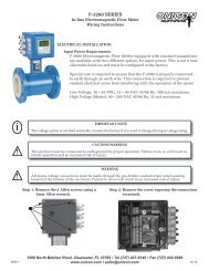
4-20 m100 ohminimperature sensor located within the shedder bar. This sensor provides an accurate temperaturemeasurement at the point where the fl ow rate is being measured. <strong>Flow</strong> meters supplied withthis option will display the medium temperature <strong>and</strong> deliver an output signal that is temperaturecompensated for mass <strong>and</strong>/or normalized fl 3.3 ELECTRICAL INSTALLATIONow.!The F-<strong>2500</strong> <strong>Series</strong> <strong>Vortex</strong>3.3 WIRING<strong>Flow</strong>TERMINATIONS<strong>Meter</strong> is a 2-wire loop powered device. Two additional wires arerequired to utilize the pulse output <strong>and</strong> a separate earth wire is recommended to minimize thepossibility of electrical The st<strong>and</strong>ard interference. F-2000 series vortex meter is a 2-wire loop powered device. Wiring connections are shownbelow.CAUTIONTake all necessary precautions to prevent moisture, dirt or debris from CAUTION entering the meter wheneverthe cover is removed from • Do the not electronics remove enclosure. covers in any wet environment• Keep dirt <strong>and</strong> debris out of electronics enclosure! • Keep threads lubricated (silicone based lubricant)To access electrical connections, remove the rear cover from the electronics enclosure.• Do not over tighten covers. Use special tool for removal only.Pulse Output (-)Pulse Output (+)4-20 mA (-)EarthConnection4-20 mA (+)Install signal cables <strong>and</strong> earth wire through the conduit connection or strain relief located on theside of the enclosure.3.3.1 Analog OutputThe F-<strong>2500</strong> 4-20mA output is an electrically isolated, passive (loop powered)2-wire output. Use 18 - 22 AWG str<strong>and</strong>ed cable with shield.• Supply voltage range: 14 – 36 VDC• Maximum load resistance: Rmax (1000 max)3.3.2 Pulse OutputThe F-<strong>2500</strong> open collector pulse output is an electrically isolated, passive 2-wireoutput. Use 18 - 22 AWG str<strong>and</strong>ed cable with shield.• Supply voltage range: 5 F-2200 – 30 VDC <strong>Series</strong> <strong>Vortex</strong> <strong>Flow</strong> <strong>Meter</strong> <strong>Installation</strong> <strong>and</strong> <strong>Operation</strong> Guide • Revised 1/0817• Maximum current: 100mA• Maximum power dissipation: 250 mW• Maximum pulse rate: 0.5 Hz1500 North Belcher Road, Clearwater, FL 33765 • Tel (727) 447-6140 • Fax (727) 442-5699 • sales@onicon.comF-<strong>2500</strong> <strong>Flow</strong> <strong>Meter</strong> Manual 11/11 - 0688-3 Page 20
3.3.3 Remote Mount Cable Wiring Instructions!CAUTIONDo not cut the remote mount cable. The cable ends contain inline filtering components.Connect cable hereas shown below.Cable wires are labeled withnumbers which correspond toconnection terminals on theremote mount junction box.Install cable through strainrelief as shown.Connect the wires to the appropriate terminalsaccording to the numbered tags on each wire asshown. Also connect earth lug to the groundingscrew as shown.Install cover tocomplete installation.1500 North Belcher Road, Clearwater, FL 33765 • Tel (727) 447-6140 • Fax (727) 442-5699 • sales@onicon.comF-<strong>2500</strong> <strong>Flow</strong> <strong>Meter</strong> Manual 11/11 - 0688-3 Page 21
!SECTION 4.0: START UP AND TROUBLESHOOTING4.1 START UP!iWhen the power is applied to the F-<strong>2500</strong> series vortex meter, alphanumeric characters willappear on the display. Initially, the meter will operate in a “TEST” mode where self diagnosticchecks are performed on the pre-amplifier <strong>and</strong> sensor circuits. Following this, configuration datais loaded from the non-volatile memory <strong>and</strong> the program advances to the measurement mode.IMPORTANT NOTEThe meter should be installed <strong>and</strong> powered for at least 15 minutes before media is allowed to flowthrough the meter.!CAUTION<strong>Flow</strong> velocity through the meter should be increased gradually until full flow is achieved.4.2 MEASUREMENT MODEIn the measurement mode, the displayindicates real-time flow, temperature <strong>and</strong>/or pressure data in the appropriate units.The top line of the display indicates thecurrent measured value. The second lineof the display indicates the programmedunits of measurement.!There are two options for displaying data inthe measurement mode. The display maybe set to automatically scroll through eachmenu page or it may be set to manually stepthrough the menu pages using the up arrowkey to advance each page. Displays operatingin the cyclic mode will advance througheach page every 6 seconds.St<strong>and</strong>ard measurement mode menu pages:!iIMPORTANT NOTEWhen measuring steam flow, condensate may form on the cool surfaces of the meter <strong>and</strong> pipingsystem when the system is started up for the first time (causing faulty measurement).1500 North Belcher Road, Clearwater, FL 33765 • Tel (727) 447-6140 • Fax (727) 442-5699 • sales@onicon.comF-<strong>2500</strong> <strong>Flow</strong> <strong>Meter</strong> Manual 11/11 - 0688-3 Page 22
F-2200 <strong>Series</strong> <strong>Vortex</strong> <strong>Flow</strong> <strong>Meter</strong> <strong>Installation</strong> <strong>and</strong> <strong>Operation</strong> Guide • Revised 1/084.3 OPERATING THE DISPLAY4.3 OPERATING THE DISPLAYPlease read the entire procedure before proceeding. Wiring diagrams are located in the Appendix. A worksheetfor checking off the following steps <strong>and</strong> recording measured values is located on the next page.key HallEffect Switch!key HallEffect switchkey HallEffect Switchkey HallEffect Switchkey HallEffect switch!iiIMPORTANT NOTEDisplay page scroll(measurement mode)key HallEffect switchDisplay page scroll(measurementmode)Do not attempt to enter the program mode without first contacting ONICON service.IMPORTANT NOTEDo not attempt to enter the program mode without fi rst contacting ONICON service.There are 3 user pushbutton interface switches located immediately below the display. Eachpushbutton switch performs a separate function. The table below describes the function of each.There are 3 user interface switches located immediately below the display. Each switch performs aseparate There are function. also 3 The corresponding table below describes Hall Effect the function switches of each that switch. perform There the are same also functions. 3 corresponding The Hall EffectHall switches Effect switches may be that activated perform without the same removing functions. the The display Hall Effect cover, switches using may the be activated magnet provided without with theremoving meter. Place the display the magnet cover, using against the the magnet cover provided in proximity with the to meter. the Hall Place Effect the magnet switch against to activate. the coverin proximity to the Hall Effect switch to activate.PROGRAMMODEONLYInterfac e S witchScroll/IncrementMode/SelectEnterS witch F unc tionScroll through measurement modemenu pages.Enter programming mode -Contact ONICON for assistancein programming.Used in programming mode.!!CAUTIONCAUTION• Do not • Do remove not remove enclosure enclosure covers covers in in any any wet wet environment.• Keep • Keep dirt <strong>and</strong> dirt <strong>and</strong> debris debris out out of of electronics enclosure.• Keep • Keep threads threads lubricated lubricated (silicone (silicone based based lubricant).• Do not over tighten covers. Use special tool for removal only.• Do not over tighten covers. Use special tool for removal only.1500 North Belcher Road, Clearwater, FL 33765 • Tel (727) 447-6140 • Fax (727) 442-5699 • sales@onicon.comF-<strong>2500</strong> <strong>Flow</strong> <strong>Meter</strong> Manual 11/11 - 0688-3 Page 23
4.4 ERROR HANDLINGThe meter can detect errors in either the test or the measurement modes. When in the measurementmode, a blinking vertical bar will appear in the top left corner of the display indicating an error hasbeen detected. If the error reporting function is enabled, error messages will be displayed asseparate menu pages. The first line of the error menu page indicates the total number of errors <strong>and</strong>the second line displays the error message. Measurement mode error messages are listed below.Error Message(display second line)NO SIGNALType DescriptionNo signal from the vortexsensorCorrective ActionRequiredNo flow. Also check for any other errors duringpower-on diagnostics. If there is a sensorproblem, contact ONICON.LOW FREQ. <strong>Vortex</strong> frequency is too low Check for flow rate lower than specified minimum.Contact ONICON.HIGH FREQ. <strong>Vortex</strong> frequency is too high Check for flow rate higher than specified maximum.Contact ONICON.LOW FLOWHIGH FLOWINV. CONFIG.ISO FAILAMP FAILCheckedduringpowerononly<strong>Flow</strong> rate lower than specifiedrangeActual flow rate higher thanspecified rangeConfiguration data in nonvolatilememory is not validSensor isolation has failedPre-amplifier section hasfailedConverter will continue to display actual flowrate. However, accuracy of measurement maysuffer.Corrective action depends on application process.If the flow rate exceeds the maximumvalue it may damage the sensor physically.Contact ONICON.Contact ONICON.Contact ONICON.PIEZO FAIL Piezo wires broken Contact ONICON.CHECK INST <strong>Flow</strong> signal quality is bad Check: 1) <strong>Flow</strong> rate, if OK; 2) Check forexcessive pipe vibration <strong>and</strong> upstream flowdisturbances; 3) Contact ONICON.LOW SIGNALHIGH SIGNALLOW.TEMP.PHY.HIGH.TEMP.PHY.T.SENS.SHORTT.SENS.OPEN<strong>Vortex</strong> signal amplitude toolow<strong>Vortex</strong> sensor signalamplitude too highOperating temperature islower than the physical limitOperating temperature ishigher than the physical limitTemperature sensor/wiresshort circuitTemperature sensor opencircuitCheck: 1) <strong>Flow</strong> rate, if OK; 2) Contact ONI-CON.This occurs in cases of high density medium.Check 1) <strong>Flow</strong> rate, if OK 2) Contact ONI-CON.Take corrective action depending on the process.Take corrective action immediately. This willcause damage to the shedder bar as well asto the electronics.Indicates a fault in the temperature sensor.Contact ONICON.1500 North Belcher Road, Clearwater, FL 33765 • Tel (727) 447-6140 • Fax (727) 442-5699 • sales@onicon.comF-<strong>2500</strong> <strong>Flow</strong> <strong>Meter</strong> Manual 11/11 - 0688-3 Page 24
4.5 TROUBLESHOOTING HINTSREPORTEDPROBLEM<strong>Flow</strong> is indicated whenno actual flow is in thepipe.POSSIBLESOLUTIONS• Mains interference due to improper earth ground connection. The protectiveearth PE terminal should be properly grounded (see page 20).• Excessive mechanical vibration in the pipe. If so, support the pipeline near themeter perpendicular to both the axis of the pipe <strong>and</strong> the axis of the bluff body.• If this problem persists at this point, contact ONICON. This problem may alsobe solved by reducing the factory set gain.Any identifiable installation issues should be corrected <strong>and</strong> any pipevibration shoud be minimized before the gain setting is changed.“CHECK INST.” erroris displayed when noflow is in the pipe.The display should normally indicate 0.0 flow rate, LOW FLOW or LOW SIGNALwhen there is no flow in the pipe. The additional CHECK INSTALL error (flowrate = 0.0 or some steady or fluctuating value) is an indication of:• Improper/inadequate earthing• Excessive pipe vibration<strong>Flow</strong> rate indicated is0.0 even with flow inthe pipe.The flow indicatedresponds to changesin the flow but theindicated value doesnot correspond to theactual flow rate. Also“CHECK INST.” Errormay appear intermittently.• The vortex sensor cable is disconnected or is not properly connected.• <strong>Flow</strong> sensor is faulty. Contact ONICON for assistance.• The meter is not properly centered on the pipeline. The axis of the meter boreshould be aligned with that of the pipe.• Gaskets at the meter are protruding into the pipe bore. The gaskets must notproject into the effective cross-section of the pipe.• Irregularities on the surface of the pipe bore. The pipe bore should be free fromirregularities at the welded joints, dirt, deposits <strong>and</strong> excessive surface roughness.• The <strong>Vortex</strong> signal is distorted due to a bi-phase medium. Bi-phase media arenot permitted. Use a moisture separator for wet steam applications to removethe moisture droplets from the steam. Use suitable filters in gas applications toremove solid particles from the flowing gas. • Incorrect angular position of themeter. Refer to Section 3.1 for the allowable mounting positions.• Insufficient upstream/downstream pipe lengths. Check that the upstream/downstream pipe lengths are of the correct minimum length as given inSection 3.1.• Error in meter factor K-Factor programming. Contact ONICON for assistance.• Check that the flow direction <strong>and</strong> the direction arrow on the meter body agree.1500 North Belcher Road, Clearwater, FL 33765 • Tel (727) 447-6140 • Fax (727) 442-5699 • sales@onicon.comF-<strong>2500</strong> <strong>Flow</strong> <strong>Meter</strong> Manual 11/11 - 0688-3 Page 25
MODEL NUMBER CODIFICATIONModel # Codification = F-25AA - BCDF = <strong>Flow</strong> <strong>Meter</strong>25 = In-line <strong>Vortex</strong> <strong>Meter</strong>AA = Diameter in Inches05 = 1/2” 04 = 4”01 = 1” 06 = 6”15 = 1.5” 08 = 8”02 = 2” 10 = 10”03 = 3” 12 = 12”B = Wafer or Flange Connection0 = Wafer1 = ANSI Class 150 Flange3 = ANSI Class 300 Flange6 = ANSI Class 600 FlangeC = Compact or Remote Mount1 = Compact Mount2 = Remote MountD = Pressure CompensationD = Pressure Compensation0 = None1 = Pressure Compensation1500 North Belcher Road, Clearwater, FL 33765 • Tel (727) 447-6140 • Fax (727) 442-5699 • sales@onicon.comF-<strong>2500</strong> <strong>Flow</strong> <strong>Meter</strong> Manual 11/11 - 0688-3 Page A-1
OPERATING RANGES FOR STEAM, WATER & AIROperating Range for Saturated SteamNominaldiameterin inches1/2 “(DN15)1”(DN25)1 1/2”(DN40)2”(DN50)3”(DN80)4”(DN100)6”(DN150)8”(DN200)10”(DN250)12”(DN300)Pressure(psig)Density(lb/ft 3 )MinimumMaximumMinimumMaximumMinimumMaximumMinimumMaximumMinimumMaximumMinimumMaximumMinimumMaximumMinimumMaximumMinimumMaximumMinimumMaximum15 50 75 100 150 200 3000.072 0.1498 1.2036 1.2569 0.3627 0.4682 0.67931114426323648101111,4022443,0724195,27894811,9571,65720,8942,56332,3093,61445,5611730538687951,7221642,9823596,53161711,2221,39825,4242,44344,4273,77868,7005,32796,87819412449271102,3231904,0234168,81171415,1401,61834,2992,82759,9364,37292,6826,165130,695lbs / hr1500 North Belcher Road, Clearwater, FL 33765 • Tel (727) 447-6140 • Fax (727) 442-5699 • sales@onicon.comF-<strong>2500</strong> <strong>Flow</strong> <strong>Meter</strong> Manual 11/11 - 0688-3 Page A-222523491,1781242,9532155,11247011,19880819,2401,83043,5893,19976,1704,946117,7866,975166,09728647591,4561473,6512556,32255913,84796023,7922,17553,9003,80094,1895,876145,6498,286205,38736741671,6671674,1802907,23663515,8511,09027,2352,47061,7014,316107,8216,675166,7289,412235,113F-<strong>2500</strong> <strong>Flow</strong> Table Water in gpm Air in cfm*<strong>Flow</strong> Rate Minimum Maximum Minimum MaximumNominal Diameter in Inches(Diameter in mm)1/2” (DN15) 1.58 22.3 2.55 34.11” (DN25) 3.56 50.2 5.75 76.71 1/2” (DN40) 8.98 126 14.4 1922” (DN50) 15.5 218 24.9 3333” (DN80) 34.1 477 54.7 7294” (DN100) 58.6 820 93.9 1,2526” (DN150) 132 1,858 213 2,8388” (DN200) 232 3,246 372 4,95910” (DN250) 359 5,019 575 7,66812” (DN300) 506 7,078 811 10,813*Values based on air at 68°F <strong>and</strong> 14.7 psia50881771,9821934,9693338,60373018,8451,25532,3792,84273,3554,967128,1857,680198,21810,830279,519
F-<strong>2500</strong> Flanged Dimensions <strong>and</strong> WeightsMETER DIMENSIONSDN 15-DN50, FLDN 80-DN100, SWSizeNomDiaPressureRatingANSIClassDimensions (inches)d D L H I WithpressuresensorWeight (lbs)Withoutpressuresensor1/2 150 0.6 3.5 7.9 10.4 5.7 11.2 9.91/2 300 0.6 3.7 7.9 10.4 5.7 12.1 10.81/2 600 0.5 3.7 7.9 10.4 5.7 12.6 11.21 150 1.1 4.3 7.9 10.4 5.7 15.0 13.71 300 1.1 4.9 7.9 10.4 5.7 17.2 15.91 600 1.0 4.9 7.9 10.4 5.7 17.9 16.51 1/2 150 1.6 4.9 7.9 10.6 5.7 19.6 18.31 1/2 300 1.6 6.1 7.9 10.6 5.7 24.3 22.9DN 15-DN50, FL1 1/2 600 1.5 6.1 7.9 10.6 5.7 26.5 25.12 150 2.1 5.9 7.9 10.8 5.7 25.6 24.32 300 2.1 6.5 7.9 10.8 5.7 28.7 27.32 600 1.9 6.5 7.9 10.8 5.7 32.0 30.63 150 3.1 7.5 7.9 11.4 6.1 45.0 43.73 300 3.1 8.3 7.9 11.4 6.1 51.6 50.33 600 2.9 8.3 7.9 11.4 6.1 52.8 52.54 150 4.0 9.1 9.8 12.2 6.5 52.9 51.64 300 4.0 10.0 9.8 12.2 6.5 70.6 69.24 600 3.8 10.8 9.8 12.2 6.5 9/290.4 89.16 150 6.1 11.0 11.8 12.8 6.9 81.1 79.86 300 6.1 12.6 11.8 12.8 6.9 114.2 112.96 600 5.8 14.0 11.8 12.8 6.9 169.3 101.98 150 8.0 13.6 11.8 13.8 7.6 146.4 145.7DN 80-DN150, FLDN 80-DN150, FL8 300 8.0 15.0 11.8 13.8 7.6 190.3 189.78 600 7.6 16.5 11.8 13.8 7.6 331.6 330.310 150 10.0 15.5 15.0 14.6 8.8 197.1 195.810 300 10.0 17.9 15.0 14.6 8.8 252.2 239.910 600 9.6 20.1 15.0 14.6 8.8 419.8 418.412 150 12.0 19.1 17.7 15.5 9.6 318.3 317.012 300 12.0 20.5 17.7 15.5 9.6 415.4 414.012 600 11.4 22.1 17.7 15.5 9.6 543.2 541.9Front ViewSide View8.34”5”9/21500 North Belcher Road, Clearwater, FL 33765 • Tel (727) 447-6140 • Fax (727) 442-5699 • sales@onicon.comF-<strong>2500</strong> <strong>Flow</strong> <strong>Meter</strong> Manual 11/11 - 0688-3 Page A-3
METER DIMENSIONSF-<strong>2500</strong> Wafer Style Dimensions <strong>and</strong> WeightsDN 15-DN50, SWSizeNomDiaPressureRatingANSIClassDimension (inches)d D L H WithpressuresensorWeight (lbs)DN 15-DN50, SWWithoutpressuresensor1/2 150 0.6 1.8 2.6 5.7 9.0 7.71/2 300 0.6 1.8 2.6 5.7 9.0 7.71/2 600 0.6 1.8 2.6 5.7 9.0 7.71 150 0.9 2.6 2.6 5.7 10.8 9.51 300 0.9 2.6 2.6 5.7 10.8 9.51 600 0.9 2.6 2.6 5.7 10.8 9.51 1/2 150 1.5 3.2 2.6 5.7 12.1 10.81 1/2 300 1.5 3.2 2.6 5.7 12.1 10.81 1/2 600 1.5 3.2 2.6 5.7 12.1 10.82 150 2.0 4.0 2.6 5.7 14.6 13.22 300 2.0 4.0 2.6 5.7 14.6 13.22 600 2.0 4.0 2.6 5.7 14.6 13.23 150 2.9 5.3 2.6 6.1 19.4 18.13 300 2.9 5.3 2.6 6.1 19.4 18.13 600 2.9 5.3 2.6 6.1 19.4 18.14 150 3.8 6.2 2.6 6.5 22.3 20.94 300 3.8 6.2 2.6 6.5 22.3 20.94 600 3.8 6.2 2.6 6.5 22.3 20.9DN 80-DN100, SWFront ViewSide View8.34”5”DN 15-DN50, FLDN 80-DN100, SWDN 15-DN50, FLDN 80-DN150, FL1500 North Belcher Road, Clearwater, FL 33765 • Tel (727) 447-6140 • Fax (727) 442-5699 • sales@onicon.comF-<strong>2500</strong> <strong>Flow</strong> <strong>Meter</strong> Manual 11/11 - 0688-3 Page A-4
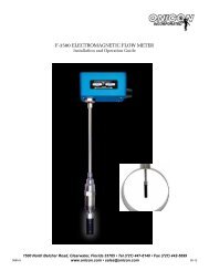
REMOTE MOUNT INSTALLATION DRAWINGS5.00”8.35”4.80”14.25”4.00”4.75”3.75” 2.50” 4.50”JUNCTION BOX!!SENSOR BODY32.8 Ft (DO NOT cut cable)iIMPORTANT NOTE<strong>Meter</strong>s provided with integral pressure compensation cannot use the remote mount transmitteroption.1500 North Belcher Road, Clearwater, FL 33765 • Tel (727) 447-6140 • Fax (727) 442-5699 • sales@onicon.comF-<strong>2500</strong> <strong>Flow</strong> <strong>Meter</strong> Manual 11/11 - 0688-3 Page A-5
CONDITIONS OF SALE1. ACCEPTANCE: The following Conditions of Sale apply to all sales of ONICON’s products. These provisions shall apply evenif ONICON fails to object to provisions appearing on, incorporated by, referenced in, or attached to Buyer’s purchase orderform. Buyer’s acceptance of delivery of ONICON’s products constitutes its acceptance of these Conditions of Sale.2. DELIVERY AND TITLE: All product shipments are F.O.B. shipping point <strong>and</strong> title passes to the Buyer at the time ONICONdelivers the merch<strong>and</strong>ise to the carrier. Risk of loss or damage to the product passes to the Buyer at the time ONICON deliversthe product to the carrier. The Buyer immediately upon receipt should inspect all shipments, <strong>and</strong> should there be any evidence ofdamage or loss in transit, Buyer must file claims or tracers upon carrier. ONICON will assist in tracing shipments upon request.3. LIMITED WARRANTY: ONICON warrants that for a period of two (2) years following the date of original shipment of anONICON product: (i) the product will conform to ONICON’s st<strong>and</strong>ard written specifications applicable to such product in effecton the date of Buyer’s order, or as modified by ONICON’s quotation or Buyer’s purchase order accepted by ONICON, (ii) theproduct will be free from defects in workmanship, <strong>and</strong> (iii) that ONICON has title to the product prior to shipment to the Buyer;provided, however, that the warranties provided herein shall be void <strong>and</strong> may not apply in the event Buyer misuses ordamages a product, including, but not limited to, any use by the Buyer of a product for an application other than one of a typeapproved by ONICON. ONICON’s sole liability <strong>and</strong> Buyer’s sole remedy for any breach of the foregoing warranty is forONICON to repair or replace, at ONICON’s option, any defective product that is returned to ONICON during the warrantyperiod. EXCEPT AS MAY BE SPECIFICALLY AGREED BY ONICON IN WRITING IN RELATION TO EACH SALE, NOOTHER WARRANTIES SHALL APPLY, WHETHER EXPRESSED, IMPLIED OR STATUTORY, AND THERE SHALL BE NOIMPLIED WARRANTIES OF MERCHANTABILITY AND FITNESS FOR A PARTICULAR PURPOSE.4. REMEDIES: ONICON’s OBLIGATION UNDER THE FOREGOING WARRANTIES IS LIMITED SOLELY TO REPAIR ORREPLACEMENT, AT ONICON’s OPTION, OF DEFECTIVE OR NONCONFORMING PRODUCTS. ONICON SHALL NOT BELIABLE FOR CONSEQUENTIAL, INDIRECT, PUNITIVE, INCIDENTAL, OR SPECIAL DAMAGES WHETHER FOUND ONCONTRACT, TORT OR ANY OTHER THEORY OF LAW. No products shall be returned to ONICON without its prior consent<strong>and</strong> transportation <strong>and</strong> insurance costs shall be prepaid. Any repair or replacement of ONICON’s products under the foregoingwarranty will be at no charge to the Buyer provided such repair is done at the ONICON factory or authorized service center.ONICON products that are repaired or replaced under this warranty will be returned to Buyer via the same method of shipmentuse to return the product to ONICON. Repair or replacement of ONICON products is conditioned upon ONICON’sacknowledgement of any alleged defect or nonconformance during the warranty period <strong>and</strong> issuance of a ReturnAuthorization number. All product returns must reference the Return Authorization number on the outside of the shippingcarton <strong>and</strong> on any paperwork referencing the return.5. PRICES AND PAYMENT TERMS: The prices set forth in the most recent quote or acknowledgement as applicable, supersedeall previous prices or quotations. All quotations are subject to change or withdrawal without notice except as may be specificallynoted on the face of the quotation. The prices shown do not include sales, excise or government charges payable by ONICON toFederal, State, or local authority. Any such tax or charge now or hereafter imposed upon the sale or shipment of the productsunder this contract will be added to the purchase price. Buyer agrees to reimburse ONICON for such tax or charge or provideONICON with an acceptable exemption certificate. Payment of invoices will be due 30 days from the date of shipment of theproducts contained therein. In the event that payment of an invoice is not received by the invoice due date, ONICON will assessa late fee not to exceed 1.5% per month or 18% per year, or the maximum allowableby law whichever is lower.6. CANCELLATION: Buyer may cancel its order, or any part of it, by sending written notice of cancellation to ONICON <strong>and</strong>paying a reasonable cancellation fee as determined by ONICON. The reasonable cancellation fee will reflect, among otherfactors, the expenses already incurred <strong>and</strong> commitments made by ONICON, sales <strong>and</strong> administrative costs <strong>and</strong> profit asdetermined by ONICON. If Buyer received a reduced price based on the quantity of products ordered, but has not purchasedthe applicable quantity at the time of cancellation, Buyer will pay the price it would have paid had ONICON’s sale price beenbased on the quantity actually purchased.7. CHANGES: If Buyer makes any changes in its drawings, designs, or specifications applicable in any contract with ONICONthat cause an increase or decrease in the cost of performance of the contract, or if such changes result in rework or obsolescence, anequitable adjustment shall be made to the contract. Such changes are subject to ONICON’s prior written consent.8. EXCUSABLE DELAY: ONICON shall under no circumstance be responsible for failure to fill any order or orders when due to: fires,floods, riots, strikes, freight embargoes or transportation delays, shortage of labor, inability to secure fuel, material supplies, or powerat current price or on account of shortages thereof, acts of God or of the public enemy, any existing or future laws or acts of theFederal or State Government (including specifically, but not exclusively, <strong>and</strong> orders, rules or regulations issued by any official oragency of any such government) affecting the conduct of ONICON’s business with which ONICON in its judgment <strong>and</strong> discretiondeems it advisable to comply as a legal or patriotic duty, or due to any cause beyond ONICON’s reasonable control.9. PATENTS: ONICON shall defend all suits or proceedings brought against Buyer or its customers arising from claimedinfringements of any patent, trademark, service mark or copyright for any product furnished by ONICON <strong>and</strong> shall indemnify itagainst all costs, fees, <strong>and</strong> damages on the condition Buyer promptly notifies ONICON in writing <strong>and</strong> provides information <strong>and</strong>assistance to enable ONICON to conduct the defense, provided that ONICON shall have no such obligation in case ofinfringement resulting from ONICON’s conformance to special requirements of Buyer. If ONICON is not able to settle any suchsuit or proceeding on acceptable terms, ONICON may, at its option, require return of the infringing product <strong>and</strong> refund thepurchase price to Buyer less a reasonable allowance for depreciation or use.10. FAIR LABOR STANDARDS ACT: ONICON represents that all products delivered under this contract are furnished inaccordance with the applicable provisions of the Fair Labor St<strong>and</strong>ards Act as amended.11. APPLICABLE LAW: This document <strong>and</strong> any resulting contract shall be governed by <strong>and</strong> construed in accordance with thelaws of the State of Florida. The courts of the State of Florida <strong>and</strong> the federal courts located in Florida shall have jurisdiction<strong>and</strong> venue with respect to litigation to this contract. In the event of litigation, the prevailing party shall be entitled to recoverattorney’s fees <strong>and</strong> costs from the non-prevailing party, including appellate attorney’s fees.12. MODIFICATIONS: These Conditions of Sale along with the prices, quantities, delivery schedules <strong>and</strong> other provisions <strong>and</strong>instructions in applicable quotations by ONICON or Buyer’s purchase orders accepted by ONICON shall constitute the entireagreement between ONICON <strong>and</strong> Buyer pertaining to any resulting contract. They can be modified only in writing.1500 North Belcher Road, Clearwater, FL 33765 • Tel (727) 447-6140 • Fax (727) 442-5699 • sales@onicon.comF-<strong>2500</strong> <strong>Flow</strong> <strong>Meter</strong> Manual 11/11 - 0688-3 Page A-6