VIESMANN - Viessmann
VIESMANN - Viessmann
VIESMANN - Viessmann

You also want an ePaper? Increase the reach of your titles
YUMPU automatically turns print PDFs into web optimized ePapers that Google loves.
<strong>VIESMANN</strong> VITOSOL<br />
Technical guide<br />
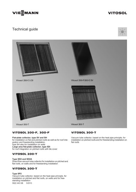
VITOSOL 200-F, 300-F<br />
Flat-plate collector, type SV and SH<br />
for installation on flat and pitched roofs as well as for roof integration<br />
and freestanding installation,<br />
type SH also for installation on walls<br />
Large area flat-plate collector, type 5DI<br />
for roof integration on pitched roofs with tile cover<br />
VITOSOL 200-T<br />
Type SD2 and SD2A<br />
Direct flow vacuum tube collector for installation on pitched and<br />
flat roofs, on walls and for freestanding installation<br />
VITOSOL 200-T<br />
Type SP2<br />
Vacuum tube collector, based on the heat pipe principle, for<br />
installation on pitched and flat roofs, on walls and for freestanding<br />
installation<br />
5822 440 GB 5/2010<br />
VITOSOL 300-T<br />
Vacuum tube collector, based on the heat pipe principle, for<br />
installation on pitched roofs and for freestanding installation on<br />
flat roofs
Index<br />
Index<br />
1. Principles 1. 1 <strong>Viessmann</strong> collector range ....................................................................................... 5<br />
1. 2 Parameters for collectors .......................................................................................... 5<br />
■ Area designations ................................................................................................. 5<br />
■ Collector efficiency ................................................................................................ 6<br />
■ Thermal capacity ................................................................................................... 7<br />
■ Idle temperature .................................................................................................... 7<br />
■ Steam production capacity ................................................................................... 7<br />
■ Solar coverage ...................................................................................................... 8<br />
1. 3 Orientation, inclination and shading of the receiver surface ..................................... 8<br />
■ Inclination of the receiver surface ......................................................................... 8<br />
■ Orientation of the receiver surface ........................................................................ 8<br />
■ Avoiding shading of the receiver surface .............................................................. 8<br />
2. Vitosol 200-F 2. 1 Product description ................................................................................................... 10<br />
■ Benefits ................................................................................................................. 10<br />
■ Delivered condition ............................................................................................... 11<br />
2. 2 Specification ............................................................................................................. 12<br />
2. 3 Approved quality ....................................................................................................... 13<br />
3. Vitosol 200-F, type 5DI 3. 1 Product description ................................................................................................... 14<br />
■ Benefits ................................................................................................................. 14<br />
■ Delivered condition ............................................................................................... 14<br />
3. 2 Specification ............................................................................................................. 15<br />
3. 3 Approved quality ....................................................................................................... 15<br />
4. Vitosol 300-F 4. 1 Product description ................................................................................................... 16<br />
■ Benefits ................................................................................................................. 16<br />
■ Delivered condition ............................................................................................... 17<br />
4. 2 Specification ............................................................................................................. 18<br />
4. 3 Approved quality ....................................................................................................... 19<br />
5. Vitosol 200-T, type SD2 5. 1 Product description ................................................................................................... 20<br />
■ Benefits ................................................................................................................. 20<br />
■ Delivered condition ............................................................................................... 21<br />
5. 2 Specification ............................................................................................................. 22<br />
5. 3 Approved quality ....................................................................................................... 23<br />
6. Vitosol 200-T, type SD2A 6. 1 Product description ................................................................................................... 24<br />
■ Benefits ................................................................................................................. 24<br />
■ Delivered condition ............................................................................................... 25<br />
6. 2 Specification ............................................................................................................. 26<br />
6. 3 Approved quality ....................................................................................................... 27<br />
7. Vitosol 200-T, type SP2 7. 1 Product description ................................................................................................... 28<br />
■ Benefits ................................................................................................................. 28<br />
■ Delivered condition ............................................................................................... 28<br />
7. 2 Specification ............................................................................................................. 29<br />
7. 3 Approved quality ....................................................................................................... 30<br />
8. Vitosol 300-T 8. 1 Product description ................................................................................................... 31<br />
■ Benefits ................................................................................................................. 31<br />
■ Delivered condition ............................................................................................... 31<br />
8. 2 Specification ............................................................................................................. 32<br />
8. 3 Approved quality ....................................................................................................... 33<br />
9. Solar control units 9. 1 Solar control module, type SM1, part no. 7429 073 ................................................. 35<br />
■ Specification .......................................................................................................... 35<br />
■ Delivered condition ............................................................................................... 35<br />
■ Approved quality ................................................................................................... 35<br />
9. 2 Vitosolic 100, type SD1, part no. Z007 387 .............................................................. 36<br />
■ Specification .......................................................................................................... 36<br />
■ Delivered condition ............................................................................................... 36<br />
■ Approved quality ................................................................................................... 36<br />
9. 3 Vitosolic 200, type SD4, part no. Z007 388 .............................................................. 37<br />
■ Specification .......................................................................................................... 37<br />
■ Delivered condition ............................................................................................... 37<br />
■ Approved quality ................................................................................................... 38<br />
2 <strong>VIESMANN</strong> VITOSOL<br />
5822 440 GB
5822 440 GB<br />
Index (cont.)<br />
9. 4 Functions .................................................................................................................. 39<br />
■ Allocation to solar control units ............................................................................. 39<br />
■ Cylinder temperature limit ..................................................................................... 39<br />
■ Collector cooling function with Vitosolic 100 and 200 ........................................... 39<br />
■ Reverse cooling function with Vitosolic 100 and 200 ............................................ 39<br />
■ Collector emergency stop ..................................................................................... 39<br />
■ Minimum collector temperature limit ..................................................................... 39<br />
■ Reduction of stagnation time with solar control module ........................................ 40<br />
■ Interval function ..................................................................................................... 40<br />
■ Cooling function in Vitosolic 200 (only in systems with one consumer) ................ 40<br />
■ Frost protection ..................................................................................................... 40<br />
■ Thermostat function with solar control module and Vitosolic 100 ......................... 40<br />
■ Vitosolic 200 thermostat function, ΔT control and time switches .......................... 40<br />
■ Speed control with solar control module ............................................................... 40<br />
■ Vitosolic 100 speed control ................................................................................... 41<br />
■ Vitosolic 200 speed control ................................................................................... 41<br />
■ Heat statement with solar control module and Vitosolic 100 ................................ 41<br />
■ Vitosolic 200 heat statement ................................................................................. 41<br />
■ Suppression of DHW cylinder reheating by the boiler with solar control module .. 41<br />
■ Suppression of DHW cylinder reheating by boiler with the Vitosolic 100 .............. 41<br />
■ Suppression of DHW cylinder reheating by boiler with the Vitosolic 200 .............. 42<br />
■ Suppression of reheating by the boiler with central heating backup, with solar<br />
control module ...................................................................................................... 43<br />
■ Auxiliary function for DHW heating with solar control module .............................. 43<br />
■ Auxiliary function for DHW heating with Vitosolic 100 .......................................... 43<br />
■ Auxiliary function for DHW heating with Vitosolic 200 .......................................... 43<br />
■ External heat exchanger with solar control module .............................................. 44<br />
■ External heat exchanger with Vitosolic 100 .......................................................... 45<br />
■ External heat exchanger with Vitosolic 200 .......................................................... 45<br />
■ Bypass circuits — optional extensions with Vitosolic 200 ..................................... 46<br />
■ Parallel relay with Vitosolic 200 ............................................................................ 47<br />
■ Cylinder 2 (to 4) on with Vitosolic 200 ................................................................... 47<br />
■ Cylinder heating with Vitosolic 200 ....................................................................... 47<br />
■ Cylinder priority control with Vitosolic 200 ............................................................ 47<br />
■ Utilisation of excess heat with Vitosolic 200 ......................................................... 47<br />
■ Cyclical heating ..................................................................................................... 47<br />
■ Relay kick with solar control module ..................................................................... 47<br />
■ Relay kick with Vitosolic 200 ................................................................................. 47<br />
■ SD module with Vitosolic 200 ............................................................................... 47<br />
9. 5 Accessories .............................................................................................................. 48<br />
■ Allocation to solar control units ............................................................................. 48<br />
■ Temperature sensor (DHW cylinder/heating water buffer cylinder/combi cylinder) 48<br />
■ Temperature sensor (DHW cylinder/heating water buffer cylinder/combi cylinder) 48<br />
■ Collector temperature sensor ................................................................................ 48<br />
■ Solar cell ............................................................................................................... 49<br />
■ Large display ......................................................................................................... 49<br />
■ Datalogger ............................................................................................................ 49<br />
■ High limit safety cut-out ......................................................................................... 50<br />
■ Control thermostat as temperature limiter (maximum limit) .................................. 50<br />
■ Temperature controller .......................................................................................... 51<br />
■ Temperature controller .......................................................................................... 51<br />
■ Stainless steel sensor well .................................................................................... 52<br />
■ Heat meter ............................................................................................................ 52<br />
■ Contactor relay ...................................................................................................... 53<br />
10. DHW cylinders 10. 1 Vitocell 100-U, type CVUA ........................................................................................ 54<br />
10. 2 Vitocell 100-B, type CVB .......................................................................................... 58<br />
10. 3 Vitocell 100-V, type CVW ......................................................................................... 64<br />
10. 4 Vitocell 300-B, type EVB ........................................................................................... 67<br />
10. 5 Vitocell 140-E, type SEI and Vitocell 160-E, type SES ............................................. 72<br />
10. 6 Vitocell 340-M, type SVK and Vitocell 360-M, type SVS .......................................... 75<br />
10. 7 Vitocell 100-V, type CVA .......................................................................................... 81<br />
10. 8 Vitocell 300-V, type EVI ............................................................................................ 87<br />
11. Installation accessories 11. 1 Solar-Divicon ............................................................................................................ 91<br />
11. 2 Connecting cable ...................................................................................................... 93<br />
11. 3 Installation kit for connection line .............................................................................. 93<br />
11. 4 Manual air vent valve ................................................................................................ 94<br />
11. 5 Air separator ............................................................................................................. 94<br />
11. 6 Quick-acting air vent valve (with tee) ........................................................................ 94<br />
11. 7 Connecting line ......................................................................................................... 94<br />
VITOSOL <strong>VIESMANN</strong> 3
Index (cont.)<br />
12. Information regarding design and<br />
operation<br />
11. 8 Solar flow and return line .......................................................................................... 95<br />
■ Connection set ...................................................................................................... 95<br />
■ Connection set ...................................................................................................... 95<br />
■ Connection set with locking ring fitting .................................................................. 95<br />
11. 9 Fill valve .................................................................................................................... 95<br />
11.10 Manual solar fill pump ............................................................................................... 96<br />
11.11 Solar expansion vessel ............................................................................................. 96<br />
11.12 Stagnation heat sink ................................................................................................. 97<br />
11.13 Freshwater module ................................................................................................... 97<br />
11.14 Automatic thermostatic mixing valve ........................................................................ 98<br />
11.15 Three-way diverter valve .......................................................................................... 98<br />
11.16 DHW circulation (threaded fitting) ............................................................................. 98<br />
12. 1 Snow load and wind load zones ............................................................................... 98<br />
12. 2 Installation information .............................................................................................. 99<br />
■ Distance from the edge of the roof ........................................................................ 99<br />
■ Routing pipework .................................................................................................. 99<br />
■ Equipotential bonding/lightning protection of the solar thermal system ................ 99<br />
12. 3 Collector fixing .......................................................................................................... 99<br />
■ Pitched roof installation — above roof installation ................................................ 100<br />
■ Above roof installation with rafter anchors ............................................................ 100<br />
■ Above roof installation with roof hooks ................................................................. 103<br />
■ Pitched roof installation – roof integration ............................................................. 105<br />
■ Flat roof installation ............................................................................................... 106<br />
■ Installation on walls ............................................................................................... 112<br />
■ Installation information for solar lines .................................................................... 114<br />
■ Installation information for thermal insulation ........................................................ 115<br />
12. 4 Sizing the solar thermal system ................................................................................ 115<br />
■ System for heating DHW ...................................................................................... 116<br />
■ System for DHW heating and central heating backup .......................................... 117<br />
■ Swimming pool water heating system – heat exchanger and collector ................ 118<br />
12. 5 Sizing the pipework ................................................................................................... 120<br />
■ Solar thermal system operating modes ................................................................ 120<br />
■ Installation examples (hydraulic connection) Vitosol-F, types SV and SH ............ 120<br />
■ Installation examples (hydraulic connection) Vitosol 200-T, type SD ................... 121<br />
■ Installation examples (hydraulic connection) Vitosol 200-T, type SP2 ................. 122<br />
■ Installation examples (hydraulic connection) Vitosol 300-T .................................. 124<br />
■ Pressure drop of the solar thermal system ........................................................... 124<br />
■ Flow velocity and pressure drop ........................................................................... 126<br />
■ Sizing the circulation pump ................................................................................... 128<br />
■ Ventilation ............................................................................................................. 128<br />
12. 6 Safety equipment ...................................................................................................... 129<br />
■ Stagnation in solar thermal systems ..................................................................... 129<br />
■ Expansion vessel .................................................................................................. 131<br />
■ Safety valve .......................................................................................................... 134<br />
■ High limit safety cut-out ......................................................................................... 134<br />
12. 7 Additional function for DHW heating ......................................................................... 134<br />
12. 8 Connecting the DHW circulation and thermostatic mixing valve .............................. 135<br />
13. Appendix 13. 1 Subsidy programs, permits and insurance ............................................................... 135<br />
13. 2 Glossary .................................................................................................................... 136<br />
■ Absorber ............................................................................................................... 136<br />
■ Absorption ............................................................................................................. 136<br />
■ Irradiance (insolation) ........................................................................................... 136<br />
■ Emission ............................................................................................................... 136<br />
■ Evacuation ............................................................................................................ 136<br />
■ Steam production capacity ................................................................................... 136<br />
■ Steam range ......................................................................................................... 136<br />
■ Heat pipe ............................................................................................................... 136<br />
■ Condenser ............................................................................................................ 136<br />
■ Convection ............................................................................................................ 136<br />
■ Standard roof pitch ................................................................................................ 136<br />
■ Selectively coated surface .................................................................................... 136<br />
■ Radiation energy ................................................................................................... 136<br />
■ Dispersion ............................................................................................................. 137<br />
■ Vacuum ................................................................................................................. 137<br />
■ Heat transfer medium ........................................................................................... 137<br />
■ Efficiency ............................................................................................................... 137<br />
14. Keyword index .............................................................................................................................................. 138<br />
4 <strong>VIESMANN</strong> VITOSOL<br />
5822 440 GB
5822 440 GB<br />
Principles<br />
Together with advanced <strong>Viessmann</strong> heating systems, solar thermal<br />
systems create an optimum system solution for DHW and swimming<br />
pool water heating, central heating backup and other low temperature<br />
applications.<br />
1.1 <strong>Viessmann</strong> collector range<br />
Flat-plate and vacuum tube collectors from <strong>Viessmann</strong> are suitable for<br />
DHW and swimming pool water heating, for central heating backup,<br />
as well as for the generation of process heat. The conversion of light<br />
into heat at the absorber is identical for both types of collector.<br />
Flat-plate collectors are easily and safely installed above and integrated<br />
into domestic roofs. Increasingly, collectors are also mounted on<br />
walls or as floorstanding units. Flat-plate collectors are more affordable<br />
than vacuum tube collectors. They are used for DHW heating systems,<br />
swimming pool water heating and for central heating backup.<br />
In vacuum tube collectors, the absorber is similar to a Thermos flask<br />
in that it is set into an evacuated glass tube. A vacuum has good thermal<br />
insulation properties. Heat losses are therefore lower than with<br />
flat-plate collectors, especially with high inside or low outside temperatures,<br />
i.e. under the particular operating conditions that are to be<br />
expected when heating or air conditioning a building.<br />
In <strong>Viessmann</strong> vacuum tube collectors, every vacuum tube can be rotated.<br />
This means the absorber can be optimally aligned to the sun even<br />
in unfavourable installation situations. Vacuum tube collectors with<br />
direct flow can also be installed horizontally on flat roofs. The yield per<br />
m 2 collector area is a little reduced in this case, but this is offset by a<br />
correspondingly larger collector area. <strong>Viessmann</strong>'s "ESOP" calculation<br />
program produces a yield comparison.<br />
1.2 Parameters for collectors<br />
Area designations<br />
B<br />
Flat-plate collector<br />
A<br />
C<br />
This technical guide includes a summary of all technical documents<br />
for the required components, as well as design and sizing information<br />
especially for systems for detached houses. This technical guide is a<br />
product-related addition to <strong>Viessmann</strong>'s "Solar thermal systems" technical<br />
guide. You can obtain a printed version from your <strong>Viessmann</strong><br />
sales consultant or download it from the <strong>Viessmann</strong> website<br />
(www.viessmann.de), where you will also find electronic aids regarding<br />
collector fixing and maintaining the correct pressure in solar thermal<br />
systems.<br />
Flat-plate collectors cannot be mounted horizontally, as the glass<br />
cover cannot be kept clean simply through rain, and the venting of the<br />
collector would be more difficult. Generally speaking, all collector types<br />
can be mounted on walls. When installed parallel to a wall (facing<br />
south), on an annual average, approximately 30 % less radiation hits<br />
the collector than in installations on 45° supports. If the main period of<br />
use falls into spring and autumn or winter (central heating backup),<br />
higher yields may still be achieved from the collectors, subject to the<br />
prevailing conditions. It should be noted that installation on walls is<br />
subject to certain legal requirements. For the rules regarding the<br />
implementation of collector systems, see the "technical rules for the<br />
use of linear supported glazing" (TRLV) issued by the Deutsches Institut<br />
für Bautechnik (DIBT) (see chapter "Technical Building Regulations").<br />
■ Gross area A<br />
Describes the external dimensions (length x width) of a collector. It<br />
is decisive when planning the installation and when calculating the<br />
roof area required, as well as for most subsidy programs when<br />
applying for subsidies.<br />
■ Absorber area B<br />
Selectively coated metal area, which is set into the collector.<br />
■ Aperture area C<br />
The aperture area is the technically relevant specification for designing<br />
a solar thermal system and for the use of sizing programs.<br />
Flat-plate collector:<br />
Area of collector cover through which solar rays can enter.<br />
Vacuum tube collector:<br />
Sum of longitudinal sections of the single tubes. Since the tubes are<br />
smaller at the top and bottom with no absorber area, the aperture<br />
area of these devices is slightly larger than the absorber area.<br />
VITOSOL <strong>VIESMANN</strong> 5<br />
1
1<br />
Principles (cont.)<br />
C<br />
Vacuum tube collector<br />
B<br />
Collector efficiency<br />
A<br />
The efficiency of a collector (see chapter "Specification" for the relevant<br />
collector) specifies the proportion of insolation hitting the aperture<br />
area that can be converted into useable heat. The efficiency depends,<br />
among other things, on the operating conditions of the collector. The<br />
calculation method is the same for all collector types.<br />
Some of the insolation striking the collectors is "lost" through reflection<br />
and absorption at the glass pane and through absorber reflection. The<br />
ratio between the insolation striking the collector and the radiation that<br />
is converted into heat on the absorber is used to calculate the optical<br />
efficiency η 0.<br />
When the collector heats up, it transfers some of that heat to the ambience<br />
through thermal conduction of the collector material, thermal<br />
radiation and convection. These losses are calculated by means of the<br />
heat loss factors k 1 and k 2 and the temperature differential ΔT (given<br />
in K) between the absorber and the ambience:<br />
ŋ = ŋ<br />
0<br />
- k 1 - ΔT - k 2<br />
- ΔT²<br />
Eg Eg<br />
Efficiency curves<br />
The optical efficiency η 0 and the heat loss factors k 1 and k 2 together<br />
with temperature differential ΔT and the irradiance E g are sufficient to<br />
determine the efficiency curve. Maximum efficiency is achieved when<br />
the differential between the absorber and ambience temperature ΔT<br />
and the thermal losses is zero. The higher the collector temperature,<br />
the higher the heat losses and the lower the efficiency.<br />
The typical operating ranges of the collectors can be read off the efficiency<br />
curves. This gives the adjustment options of the collectors.<br />
Typical operating ranges (see following diagram):<br />
1 Solar thermal system for DHW at low coverage<br />
2 Solar thermal system for DHW at higher coverage<br />
3 Solar thermal systems for DHW and solar central heating backup<br />
4 Solar thermal systems for process heat/solar-powered air conditioning<br />
6 <strong>VIESMANN</strong> VITOSOL<br />
5822 440 GB
5822 440 GB<br />
Principles (cont.)<br />
Efficiency<br />
0.85<br />
0.80<br />
0.70<br />
0.60<br />
0.50<br />
0.40<br />
0.30<br />
0.20<br />
0 20 40 60 80 100<br />
Temperature differential in K<br />
A Vitosol 200-F<br />
B Vitosol 200-F, type 5DI<br />
C Vitosol 300-F<br />
Thermal capacity<br />
The thermal capacity in kJ/(m 2 · K) indicates the amount of heat absorbed<br />
by the collector per m 2 and K. This heat is only available to the<br />
system to a limited extent.<br />
Idle temperature<br />
The idle temperature is the maximum temperature that the collector<br />
can reach during insolation of 1000 W/m 2 .<br />
Steam production capacity<br />
The steam production capacity in W/m 2 indicates the maximum output<br />
at which a collector produces steam during stagnation and transfers it<br />
to the system, when evaporation occurs.<br />
D Vitosol 200-T, type SD<br />
E Vitosol 200-T, type SP2<br />
F Vitosol 300-T<br />
If no heat is drawn from the collector, it will heat up until it reaches the<br />
idle temperature. In this state, the thermal losses are of the same<br />
magnitude as the radiation absorbed.<br />
VITOSOL <strong>VIESMANN</strong> 7<br />
1
1<br />
Principles (cont.)<br />
Solar coverage<br />
Solar coverage<br />
in %<br />
100<br />
90<br />
80<br />
70<br />
60 A<br />
50<br />
40<br />
30<br />
20<br />
10<br />
B<br />
300 350 400 450 500 550<br />
Energy (yield) in kWh/(m²/p.a.)<br />
A Conventional sizing for DHW systems in detached houses<br />
B Conventional sizing for large solar thermal systems<br />
1.3 Orientation, inclination and shading of the receiver surface<br />
Inclination of the receiver surface<br />
600<br />
The yield of a solar thermal system varies depending on the inclination<br />
and orientation of the collector area. If the receiver surface is angled,<br />
the angle of incidence changes, as does the irradiance, and consequently<br />
the amount of energy. This is greatest when the radiation hits<br />
the receiver surface at right angles. In our latitudes, this case never<br />
arises relative to the horizontal. Consequently, the inclination of the<br />
receiver surface can optimise the yield. In Germany, a receiver surface<br />
angled 35° receives approx. 12 % more energy when oriented towards<br />
the south (compared with a horizontal position).<br />
Orientation of the receiver surface<br />
An additional factor for calculating the amount of energy that can be<br />
expected is the orientation of the receiver surface. In the northern<br />
hemisphere, an orientation towards south is ideal. The following figure<br />
shows the interaction of orientation and inclination. Relative to the<br />
horizontal, greater or lesser yields result. A range for optimum yield of<br />
a solar thermal system can be defined between south-east and southwest<br />
and at angles of inclination between 25 and 70°. Greater deviations,<br />
for example, for installation on walls, can be compensated for by<br />
a correspondingly larger collector area.<br />
±0%<br />
-15% +10%<br />
+5%<br />
-40% -20%<br />
-25%<br />
West South<br />
South-west<br />
Avoiding shading of the receiver surface<br />
±0%<br />
+10% -15%<br />
+5%<br />
-20% -40%<br />
Looking at the installation of a collector facing south, we recommend<br />
that the area between south-east and south-west is kept free of shading<br />
(at an angle towards the horizon of up to 20°). It should be remembered<br />
that the system is to operate for longer than 20 years, and that<br />
during this time, for example, trees would grow substantially.<br />
-25%<br />
South East<br />
South-east<br />
The solar coverage rate indicates what percentage of the energy<br />
required annually for DHW applications can be covered by the solar<br />
thermal system.<br />
Designing a solar thermal system always entails finding a good compromise<br />
between yield and solar coverage. The higher the selected<br />
solar coverage, the more conventional energy is saved.<br />
However, this is linked to an excess of heat in summer. This means a<br />
lower average collector efficiency and consequently lower yields<br />
(energy in kWh) per m 2 absorber area.<br />
8 <strong>VIESMANN</strong> VITOSOL<br />
5822 440 GB
5822 440 GB<br />
Principles (cont.)<br />
20°<br />
VITOSOL <strong>VIESMANN</strong> 9<br />
1
2<br />
Vitosol 200-F<br />
2.1 Product description<br />
The main component of the Vitosol 200-F, type SV2A/SH2A is the<br />
highly selectively coated absorber. It ensures a high absorption of<br />
insolation and low emission of thermal radiation. A meander-shaped<br />
copper pipe through which the heat transfer medium flows is part of<br />
the absorber.<br />
The heat transfer medium absorbs the absorber heat through the copper<br />
pipe. The absorber is encased in a highly insulated collector housing<br />
that minimises the thermal losses of the collector.<br />
The high-grade thermal insulation provides temperature stability and<br />
is free from gas emissions. The cover comprises a solar glass panel.<br />
The glass has a very low iron content, thereby reducing reflection losses.<br />
A Solar glass cover, 3.2 mm<br />
B Aluminium cover strip<br />
C Pane gasket<br />
D Absorber<br />
E Meander-shaped copper pipe<br />
Benefits<br />
■ Powerful flat-plate collector with a highly selectively coated<br />
absorber.<br />
■ Absorber designed as meander layout with integral headers. Up to<br />
12 collectors can be linked in parallel.<br />
■ Universal application for above roof, roof integration and freestanding<br />
installation – with vertical or horizontal orientation. Type SH is<br />
suitable for installation on walls.<br />
■ Attractive collector design; frame in RAL 8019 (brown). Upon<br />
request, the frame is also available in all other RAL colours.<br />
■ The selectively coated absorber, the cover made from low ferrous<br />
solar glass and the highly effective thermal insulation ensure high<br />
solar yields.<br />
Up to 12 collectors can be combined together to create a single collector<br />
array. For this purpose, the standard delivery includes flexible<br />
connecting pipes with O-rings.<br />
A connection set with locking ring fittings enables the collector array<br />
to be readily connected to the pipes of the solar circuit. The collector<br />
temperature sensor is mounted in a sensor well set in the solar circuit<br />
flow.<br />
The Vitosol 200-F, type SV2B/SH2B with a special absorber coating<br />
is designed for coastal regions (see chapter "Specification").<br />
A<br />
B<br />
C<br />
D<br />
E<br />
F<br />
G<br />
H<br />
K<br />
F Melamine epoxy foam insulation<br />
G Melamine epoxy foam insulation<br />
H Aluminium frame in RAL 8019<br />
K Steel bottom plate with an aluminium-zinc coating<br />
■ Permanently sealed and high stability through all-round folded aluminium<br />
frame and seamless pane gasket.<br />
■ Puncture-proof and corrosion-resistant back panel.<br />
■ Easy to assemble <strong>Viessmann</strong> fixing system with statically-tested and<br />
corrosion-resistant components made from stainless steel and aluminium<br />
– standard for all <strong>Viessmann</strong> collectors.<br />
■ Quick and reliable collector connection through a flexible corrugated<br />
stainless steel pipe plug-in connector.<br />
10 <strong>VIESMANN</strong> VITOSOL<br />
5822 440 GB
5822 440 GB<br />
Vitosol 200-F (cont.)<br />
Delivered condition<br />
The Vitosol 200-F is delivered fully assembled ready to connect. <strong>Viessmann</strong> offers complete solar heating systems with Vitosol 200-F<br />
(packs) for DHW heating and/or central heating backup (see pack<br />
pricelist).<br />
VITOSOL <strong>VIESMANN</strong> 11<br />
2
2<br />
Vitosol 200-F (cont.)<br />
2.2 Specification<br />
Vitosol 200-F is available with 2 different absorber coatings. Type<br />
SV2B/SH2B has a special absorber coating that allows these collectors<br />
to be used in coastal regions.<br />
Distance to the coast:<br />
■ up to 100 m:<br />
only use type SV2B/SH2B<br />
■ between 100 and 1000 m:<br />
type SV2B/SH2B is recommended<br />
Note<br />
<strong>Viessmann</strong> does not accept liability when type SV2A/SH2A is used in<br />
such regions.<br />
Type SV2A SH2A SV2B SH2B<br />
Gross area<br />
(required when applying for subsidies)<br />
m2 2.51<br />
Absorber area m2 2.32<br />
Aperture area m2 2.33<br />
Installation position (see figure below) A (above roof/ B (above roof/ A (above roof/ B (above roof/<br />
roof integration), roof integration), roof integration), roof integration),<br />
C, D<br />
C, D, E C, D<br />
C, D, E<br />
Spacing between collectors<br />
Dimensions<br />
mm 21<br />
Width mm 1056 2380 1056 2380<br />
Height mm 2380 1056 2380 1056<br />
Depth mm 90 90 90 90<br />
The following values apply to the absorber area:<br />
– Optical efficiency % 79.3 78.3<br />
– Thermal loss correction value k1 W/(m2 · K) 4.04 4.07<br />
– Thermal loss correction value k2 W/(m2 · K2 ) 0,0182 0,016<br />
Thermal capacity kJ/(m2 · K) 5.0 4.6<br />
Weight kg 40.9 42.6<br />
Liquid content<br />
(heat transfer medium)<br />
litres 1.83 2.48 1.83 2.48<br />
Permiss. operating pressure<br />
(see chapter "Solar expansion vessel")<br />
bar 6<br />
Max. idle temperature<br />
Steam output<br />
°C 186 185<br />
– Favourable installation position W/m2 60<br />
– Unfavourable installation position W/m2 100<br />
Connection Ø mm 22<br />
B<br />
C<br />
A<br />
E<br />
D<br />
12 <strong>VIESMANN</strong> VITOSOL<br />
5822 440 GB
5822 440 GB<br />
Vitosol 200-F (cont.)<br />
2380<br />
2200<br />
90<br />
Type SV2A/SV2B<br />
1056<br />
KR Collector return (inlet)<br />
KV Collector flow (outlet)<br />
876<br />
1056<br />
90<br />
Type SH2A/SH2B<br />
KR Collector return (inlet)<br />
KV Collector flow (outlet)<br />
2.3 Approved quality<br />
2380<br />
90<br />
51<br />
KV<br />
KR<br />
The collectors meet the requirements of the "Blue Angel" certificate of<br />
environmental excellence to RAL UZ 73.<br />
Tested in accordance with Solar KEYMARK and EN 12975.<br />
90<br />
51<br />
KV<br />
KR<br />
CE designation according to current EC Directives.<br />
VITOSOL <strong>VIESMANN</strong> 13<br />
2
3<br />
Vitosol 200-F, type 5DI<br />
3.1 Product description<br />
The main component of the Vitosol 200-F, type 5DI, is the highly<br />
selectively coated copper absorber. It ensures a high absorption of<br />
insolation and low emission of thermal radiation. Copper pipes are fitted<br />
to the absorber through which the heat transfer medium flows.<br />
The heat transfer medium absorbs the absorber heat through the copper<br />
pipe. The absorber is encased in a highly insulated collector housing<br />
that minimises the thermal losses of the collector.<br />
The high-grade thermal insulation provides temperature stability and<br />
is free from gas emissions. The cover comprises a solar glass panel.<br />
The glass has a very low iron content, thereby reducing reflection losses.<br />
A Solar glass cover, 4 mm<br />
B Aluminium cover frame<br />
C Harp-shaped absorber made from copper<br />
D Aluminium housing, natural finish<br />
E Mineral fibre insulating strips<br />
Benefits<br />
■ Large flat-plate collector with a highly selectively coated absorber.<br />
■ High efficiency through highly selectively coated absorber, integral<br />
piping and highly effective insulation.<br />
Delivered condition<br />
The collector is delivered complete with roofing frame, connecting<br />
pipes and lifting eyes.<br />
At the back of the collector are flexible, thermally insulated flow and<br />
return pipes as well as the sensor well for the collector temperature<br />
sensor.<br />
Vitosol 200-F, type 5DI, are designed exclusively for roof integration.<br />
F Thermal insulation made from mineral fibre<br />
G Reinforcing frame<br />
H Flexible connecting pipe with thermal insulation<br />
K Mounting hooks<br />
■ Absorber area: 4.76 m 2<br />
■ Quick installation due to the roofing frame fitted onto the collector,<br />
flexible connections and lifting eyes.<br />
14 <strong>VIESMANN</strong> VITOSOL<br />
5822 440 GB
5822 440 GB<br />
Vitosol 200-F, type 5DI (cont.)<br />
3.2 Specification<br />
Gross area<br />
(required when applying for subsidies)<br />
m2 5.25<br />
Absorber area m2 4.65<br />
Aperture area m2 Dimensions<br />
4.85<br />
Width mm 2570<br />
Height mm 2040<br />
Depth<br />
The following values apply to the absorber area:<br />
mm 116<br />
– Optical efficiency % 81.9<br />
– Thermal loss correction value k1 W/(m2 · K) 3.92<br />
– Thermal loss correction value k2 W/(m2 · K2 ) 0.0234<br />
Thermal capacity kJ/(m2 · K) 6.4<br />
Weight kg 105<br />
Liquid content<br />
(heat transfer medium)<br />
litres 4.2<br />
Permiss. operating pressure bar 6<br />
Max. idle temperature °C 198<br />
Steam output W/m2 100<br />
Connection Ø mm 22<br />
Idle temperature<br />
Temperature at the hottest part of the collector when no heat is drawn<br />
off, at 1000 W global radiation.<br />
KR Collector return (inlet)<br />
KV Collector flow (outlet)<br />
3.3 Approved quality<br />
2870<br />
2570<br />
The collectors meet the requirements of the "Blue Angel" certificate of<br />
environmental excellence to RAL UZ 73.<br />
Tested in accordance with Solar KEYMARK and EN 12975.<br />
2445<br />
KR,<br />
KV<br />
116<br />
35 2040<br />
CE designation according to current EC Directives.<br />
VITOSOL <strong>VIESMANN</strong> 15<br />
3
4<br />
Vitosol 300-F<br />
4.1 Product description<br />
The main component of the Vitosol 300-F, type SV3A/SH3A, is the<br />
highly selectively coated absorber and the cover with an anti-reflex<br />
glass pane. This cover significantly improves the optical efficiency of<br />
the collector. The absorber ensures high absorption of insolation and<br />
low emissions of thermal radiation. A meander-shaped copper pipe<br />
through which the heat transfer medium flows is part of the absorber.<br />
The heat transfer medium absorbs the absorber heat through the copper<br />
pipe. The absorber is encased in a highly insulated collector housing<br />
that minimises the thermal losses of the collector.<br />
The high-grade thermal insulation is resistant to temperature, releases<br />
no gas and is optimised for the demands made of a high performance<br />
collector.<br />
A Cover made from solar glass with an anti-reflex coating, 3.2 mm<br />
B Aluminium cover strip<br />
C Pane gasket<br />
D Absorber<br />
E Meander-shaped copper pipe<br />
Benefits<br />
■ High performance flat-plate collector with anti-reflex glass.<br />
■ Attractive collector design; frame in RAL 8019 (brown). Upon<br />
request, the frame is also available in any other RAL colour.<br />
■ Absorber designed as meander layout with integral headers. Up to<br />
12 collectors can be linked in parallel.<br />
■ Universal application for above roof, roof integration and freestanding<br />
installation – with vertical or horizontal orientation. Type SH is<br />
suitable for installation on walls.<br />
■ High efficiency through highly selectively coated absorber and cover<br />
made from translucent anti-reflex glass.<br />
Up to 12 collectors can be combined together to create a single collector<br />
array. For this purpose, the standard delivery includes flexible<br />
connecting pipes with O-rings.<br />
A connection set with locking ring fittings enables the collector array<br />
to be readily connected to the pipes of the solar circuit. The collector<br />
temperature sensor is mounted in a sensor well set in the solar circuit<br />
flow.<br />
The Vitosol 300-F, type SV3B/SH3B with a special absorber coating<br />
is designed for coastal regions (see chapter "Specification").<br />
A<br />
B<br />
C<br />
D<br />
E<br />
F<br />
G<br />
H<br />
K<br />
F Melamine epoxy foam insulation<br />
G Melamine epoxy foam insulation<br />
H Aluminium frame in RAL 8019<br />
K Steel bottom plate with an aluminium-zinc coating<br />
■ Permanently sealed and high stability through all-round folded aluminium<br />
frame and seamless pane gasket.<br />
■ Puncture-proof and corrosion-resistant back panel made from zinc<br />
plated sheet steel.<br />
■ Easy to assemble <strong>Viessmann</strong> fixing system with statically-tested and<br />
corrosion-resistant components made from stainless steel and aluminium<br />
– standard for all <strong>Viessmann</strong> collectors.<br />
■ Quick and reliable collector connection through a flexible corrugated<br />
stainless steel pipe plug-in connector.<br />
16 <strong>VIESMANN</strong> VITOSOL<br />
5822 440 GB
5822 440 GB<br />
Vitosol 300-F (cont.)<br />
Delivered condition<br />
The Vitosol 300-F is delivered fully assembled ready to connect. <strong>Viessmann</strong> offers complete solar heating systems with Vitosol 300-F<br />
(packs) for DHW heating and/or central heating backup (see pack<br />
pricelist).<br />
VITOSOL <strong>VIESMANN</strong> 17<br />
4
4<br />
Vitosol 300-F (cont.)<br />
4.2 Specification<br />
Vitosol 300-F is available with 2 different absorber coatings. Type<br />
SV3B/SH3B has a special absorber coating that allows these collectors<br />
to be used in coastal regions.<br />
Distance to the coast:<br />
■ up to 100 m:<br />
only use type SV3B/SH3B<br />
■ between 100 and 1000 m:<br />
type SV3B/SH3B is recommended<br />
Note<br />
<strong>Viessmann</strong> does not accept liability when type SV3A/SH3A is used in<br />
such regions.<br />
Type SV3A SH3A SV3B SH3B<br />
Gross area<br />
(required when applying for subsidies)<br />
m2 2.51<br />
Absorber area m2 2.32<br />
Aperture area m2 2.33<br />
Installation position (see figure below) A (above roof/ B (above roof/ A (above roof/ B (above roof/<br />
roof integration), roof integration), roof integration), roof integration),<br />
C, D<br />
C, D, E C, D<br />
C, D, E<br />
Spacing between collectors<br />
Dimensions<br />
mm 21<br />
Width mm 1056 2380 1056 2380<br />
Height mm 2380 1056 2380 1056<br />
Depth mm 90 90 90 90<br />
The following values apply to the absorber area:<br />
– Optical efficiency % 83.4 80.3<br />
– Thermal loss correction value k1 W/(m2 · K) 3.66 3.77<br />
– Thermal loss correction value k2 W/(m2 · K2 ) 0,0169 0,0156<br />
Thermal capacity kJ/(m2 · K) 5.0 4.6 4.6 4.6<br />
Weight kg 41.3 43.1<br />
Liquid content<br />
(heat transfer medium)<br />
litres 1.83 2.48 1.83 2.48<br />
Permiss. operating pressure<br />
(see chapter "Solar expansion vessel")<br />
bar 6<br />
Max. idle temperature<br />
Steam output<br />
°C 206 205<br />
– Favourable installation position W/m2 60<br />
– Unfavourable installation position W/m2 100<br />
Connection Ø mm 22<br />
B<br />
C<br />
A<br />
E<br />
D<br />
18 <strong>VIESMANN</strong> VITOSOL<br />
5822 440 GB
5822 440 GB<br />
Vitosol 300-F (cont.)<br />
2380<br />
2200<br />
90<br />
Type SV3A/SV3B<br />
1056<br />
KR Collector return (inlet)<br />
KV Collector flow (outlet)<br />
876<br />
1056<br />
90<br />
Type SH3A/SH3B<br />
KR Collector return (inlet)<br />
KV Collector flow (outlet)<br />
4.3 Approved quality<br />
2380<br />
90<br />
51<br />
KV<br />
KR<br />
The collectors meet the requirements of the "Blue Angel" certificate of<br />
environmental excellence to RAL UZ 73.<br />
Tested in accordance with Solar KEYMARK and EN 12975.<br />
90<br />
51<br />
KV<br />
KR<br />
CE designation according to current EC Directives.<br />
VITOSOL <strong>VIESMANN</strong> 19<br />
4
5<br />
Vitosol 200-T, type SD2<br />
5.1 Product description<br />
A Header casing<br />
B Melamine epoxy foam insulation<br />
C Return pipe<br />
D Coaxial manifold and distributor pipe<br />
E Coaxial heat exchanger pipe<br />
F Absorber<br />
G Evacuated glass tube<br />
The Vitosol 200-T vacuum tube collector is available in the following<br />
versions:<br />
■ 1 m 2 with 10 tubes<br />
■ 2 m 2 with 20 tubes<br />
■ 3 m 2 with 30 tubes.<br />
Benefits<br />
■ Highly efficient, direct flow vacuum tube collector for high solar<br />
energy utilisation.<br />
■ Universal application through vertical or horizontal installation in any<br />
location, either on rooftops or on walls.<br />
■ Easy and safe connection of the individual tubes through an innovative<br />
plug-in system.<br />
■ The absorber areas integrated into the vacuum tubes are not susceptible<br />
to contamination.<br />
■ Tubes can be rotated for optimum orientation towards the sun,<br />
thereby maximising the energy yield.<br />
The Vitosol 200-T can be installed on pitched roofs, flat roofs, on walls<br />
and as a freestanding collector.<br />
On pitched roofs the collectors may be positioned in line (tubes at right<br />
angles to the roof ridge) or across (tubes parallel to the roof ridge).<br />
■ DHW heating systems:<br />
The collectors may be positioned vertically (tubes at right angles to<br />
the ridge of the roof) or horizontally (tubes parallel to the ridge of the<br />
roof).<br />
■ Systems to back up central heating:<br />
The collectors should be installed horizontally (tubes parallel to the<br />
ridge of the roof) with connection from below. This will positively<br />
influence the stagnation characteristics.<br />
The vacuum in the glass tubes ensures optimum thermal insulation.<br />
Convection losses between the glass tube and the absorber are almost<br />
completely eliminated. This enables the utilisation of even low radiation<br />
levels (diffused radiation).<br />
A highly selectively coated copper absorber is integrated into each<br />
vacuum tube. It ensures high absorption of insolation and low emissions<br />
of thermal radiation.<br />
A coaxial heat exchanger pipe, through which the heat transfer<br />
medium flows, is arranged on the absorber. The heat transfer medium<br />
absorbs heat from the absorber via the heat exchanger pipe.<br />
The heat exchanger pipe feeds into a distributor pipe.<br />
To fully utilise the available solar energy, every vacuum tube is able to<br />
pivot so that the absorber can be turned towards the sun.<br />
Up to 5 collectors can be joined in series to create a single collector<br />
array (collector arrays arranged in series should be of the same<br />
size).<br />
For this purpose, the standard delivery includes flexible connecting<br />
pipes with O-rings.<br />
The flow and return pipes integrated into the connecting casing enable<br />
the connection of the solar flow and solar return pipes of several collectors<br />
on one side.<br />
A connection set with locking ring fittings enables the collector array<br />
to be readily connected to the pipes of the solar circuit. Install the collector<br />
temperature sensor in a sensor well in the flow pipe of the solar<br />
heating circuit.<br />
■ Highly effective thermal insulation of the header casing for minimum<br />
thermal losses.<br />
■ Easy assembly through the <strong>Viessmann</strong> fixing system and corrugated<br />
stainless steel plug-in connectors.<br />
■ The flow and return connection on one side through the integral<br />
header inside the header casing minimises the effort required in<br />
connection with pipework.<br />
■ Attractive collector design, header casing in RAL 8019 (brown).<br />
20 <strong>VIESMANN</strong> VITOSOL<br />
5822 440 GB
5822 440 GB<br />
Vitosol 200-T, type SD2 (cont.)<br />
Delivered condition<br />
Packed in separate cartons:<br />
■ Vacuum tubes, 10 pce. per packing unit<br />
■ Header casing with mounting rails<br />
<strong>Viessmann</strong> offers complete solar thermal systems with Vitosol 200-T<br />
(packs) for DHW heating (see pack pricelist).<br />
VITOSOL <strong>VIESMANN</strong> 21<br />
5
5<br />
Vitosol 200-T, type SD2 (cont.)<br />
5.2 Specification<br />
Type, SD2 1 m2 2 m2 3 m2 Number of tubes 10 20 30<br />
Gross area<br />
(required when applying for subsidies)<br />
m2 1.44 2.88 4.32<br />
Absorber area m2 1.03 2.05 3.07<br />
Aperture area m2 1.06 2.11 3.17<br />
Installation position (see figure below) A, B, C, D, E, F<br />
Spacing between collectors<br />
Dimensions<br />
mm 47 47 47<br />
Width a mm 709 1418 2127<br />
Height b mm 2031 2031 2031<br />
Depth c<br />
The following values apply to the absorber area:<br />
mm 143 143 143<br />
– Optical efficiency % 82.0 82.0 83.2<br />
– Thermal loss correction value k1 W/(m2 · K) 1.62 1.62 1.87<br />
– Thermal loss correction value k2 W/(m2 · K2 ) 0.0068 0.0068 0.0041<br />
Thermal capacity kJ/(m2 · K) 9.8 9.8 9.8<br />
Weight kg 26 51 76<br />
Liquid content<br />
(heat transfer medium)<br />
litres 2.2 4.2 6.2<br />
Permiss. operating pressure<br />
(see chapter "Solar expansion vessel")<br />
bar 6 6 6<br />
Max. idle temperature<br />
Steam output<br />
°C 295 282 282<br />
– Favourable installation position W/m2 100 100 100<br />
– Unfavourable installation position W/m2 200 200 200<br />
Connection Ø mm 22 22 22<br />
B<br />
C<br />
D<br />
A<br />
F<br />
E<br />
22 <strong>VIESMANN</strong> VITOSOL<br />
5822 440 GB
5822 440 GB<br />
Vitosol 200-T, type SD2 (cont.)<br />
KR Collector return<br />
KV Collector flow<br />
5.3 Approved quality<br />
a<br />
b<br />
Ø 65<br />
The collectors meet the requirements of the "Blue Angel" certificate of<br />
environmental excellence to RAL UZ 73.<br />
Tested in accordance with Solar KEYMARK and EN 12975.<br />
c<br />
KR<br />
KV<br />
CE designation according to current EC Directives.<br />
VITOSOL <strong>VIESMANN</strong> 23<br />
5
6<br />
Vitosol 200-T, type SD2A<br />
6.1 Product description<br />
A Header casing<br />
B Melamine epoxy foam insulation<br />
C Return pipe<br />
D Coaxial manifold and distributor pipe<br />
E Coaxial heat exchanger pipe<br />
F Absorber<br />
G Evacuated glass tube<br />
The Vitosol 200-T vacuum tube collector is available in the following<br />
versions:<br />
Benefits<br />
■ Highly efficient, direct flow vacuum tube collector for high solar<br />
energy utilisation.<br />
■ Universal application through vertical or horizontal installation in any<br />
location, either on rooftops or on walls.<br />
■ Easy and safe connection of the individual tubes through an innovative<br />
plug-in system.<br />
■ The absorber areas integrated into the vacuum tubes are not susceptible<br />
to contamination.<br />
■ Tubes can be rotated for optimum orientation towards the sun,<br />
thereby maximising the energy yield.<br />
■ 2 m 2 with 20 tubes<br />
■ 3 m 2 with 30 tubes.<br />
The Vitosol 200-T can be installed on pitched roofs, flat roofs, on walls<br />
and as a freestanding collector.<br />
On pitched roofs the collectors may be positioned in line (tubes at right<br />
angles to the roof ridge) or across (tubes parallel to the roof ridge).<br />
■ DHW heating systems:<br />
The collectors may be positioned vertically (tubes vertical, relative<br />
to the roof ridge) or horizontally (tubes parallel to the roof ridge).<br />
■ Systems to back up central heating:<br />
The collectors should be installed horizontally (tubes parallel to the<br />
roof ridge). This will positively influence the stagnation characteristics.<br />
The vacuum in the glass tubes ensures optimum thermal insulation.<br />
Convection losses between the glass tube and the absorber are almost<br />
completely eliminated. This enables even low radiation levels to be<br />
utilised.<br />
Each vacuum tube contains a highly selectively coated copper<br />
absorber. It ensures high absorption of insolation and low emissions<br />
of thermal radiation.<br />
A coaxial heat exchanger pipe, through which the heat transfer<br />
medium flows, is arranged on the absorber. The heat transfer medium<br />
absorbs heat from the absorber via the heat exchanger pipe.<br />
The heat exchanger pipe feeds into a distributor pipe.<br />
To fully utilise the available solar energy, every vacuum tube is able to<br />
pivot so that the absorber can be turned towards the sun.<br />
Up to 15 m 2 collector surface can be joined in series to create a single<br />
collector array (collectors arranged in series should be of the same<br />
size).<br />
For this purpose, the standard delivery includes flexible connecting<br />
pipes with O-rings.<br />
The flow and return pipes integrated into the connecting casing enable<br />
the connection of the solar flow and solar return pipes of several collectors<br />
on one side.<br />
A connection set with locking ring fittings enables the collector array<br />
to be readily connected to the pipes of the solar circuit. Install the collector<br />
temperature sensor in a sensor well in the flow pipe of the solar<br />
heating circuit.<br />
■ Highly effective thermal insulation of the header casing for minimum<br />
thermal losses.<br />
■ Easy assembly through the <strong>Viessmann</strong> fixing system and corrugated<br />
stainless steel plug-in connectors.<br />
■ The flow and return connection on one side through the integral<br />
header inside the header casing minimises the effort required in<br />
connection with pipework.<br />
■ Attractive collector design, header casing in RAL 8019 (brown).<br />
24 <strong>VIESMANN</strong> VITOSOL<br />
5822 440 GB
5822 440 GB<br />
Vitosol 200-T, type SD2A (cont.)<br />
Delivered condition<br />
Packed in separate cartons:<br />
■ Vacuum tubes, 10 pce. per packing unit<br />
■ Header casing with mounting rails<br />
<strong>Viessmann</strong> offers complete solar thermal systems with Vitosol 200-T<br />
(packs) for DHW heating (see pack pricelist).<br />
VITOSOL <strong>VIESMANN</strong> 25<br />
6
6<br />
Vitosol 200-T, type SD2A (cont.)<br />
6.2 Specification<br />
Type SD2A 2 m2 3 m2 Number of tubes 20 30<br />
Gross area<br />
(required when applying for subsidies)<br />
m2 2.88 4.32<br />
Absorber area m2 2.01 3.02<br />
Aperture area m2 2.14 3.23<br />
Installation position (see figure below) A, B, C, D, E, F<br />
Spacing between collectors<br />
Dimensions<br />
mm 47 47<br />
Width a mm 1418 2127<br />
Height b mm 2043 2043<br />
Depth c<br />
The following values apply to the absorber area:<br />
mm 143 143<br />
– Optical efficiency % 78.9 79.1<br />
– Thermal loss correction value k1 W/(m2 · K) 1.36 1.10<br />
– Thermal loss correction value k2 W/(m2 · K2 ) 0.0075 0.0076<br />
Thermal capacity kJ/(m2 · K) 10.0 10.1<br />
Weight kg 61 95<br />
Liquid content<br />
(heat transfer medium)<br />
litres 4.2 6.2<br />
Permiss. operating pressure<br />
(see chapter "Solar expansion vessel")<br />
bar 6 6<br />
Max. idle temperature<br />
Steam output<br />
°C 295 295<br />
– Favourable installation position W/m2 100 100<br />
– Unfavourable installation position W/m2 200 200<br />
Connection Ø mm 22 22<br />
B<br />
C<br />
D<br />
A<br />
F<br />
E<br />
26 <strong>VIESMANN</strong> VITOSOL<br />
5822 440 GB
5822 440 GB<br />
Vitosol 200-T, type SD2A (cont.)<br />
KR Collector return<br />
KV Collector flow<br />
6.3 Approved quality<br />
a<br />
b<br />
Ø 65<br />
The collectors meet the requirements of the "Blue Angel" certificate of<br />
environmental excellence to RAL UZ 73.<br />
Tested in accordance with Solar KEYMARK and EN 12975.<br />
c<br />
KR<br />
KV<br />
CE designation according to current EC Directives.<br />
VITOSOL <strong>VIESMANN</strong> 27<br />
6
7<br />
Vitosol 200-T, type SP2<br />
7.1 Product description<br />
A<br />
B<br />
C<br />
D<br />
E<br />
E<br />
C<br />
D<br />
A Twin pipe heat exchanger<br />
B Adaptor<br />
C Absorber<br />
Benefits<br />
■ Highly efficient vacuum tube collector based on the heat pipe principle<br />
for high operational reliability.<br />
■ Universal application through vertical or horizontal installation in any<br />
location, either on rooftops, walls or for freestanding installation.<br />
■ The absorber areas with Sol-titanium coating that are integrated into<br />
the vacuum tubes, are not susceptible to contamination.<br />
■ Efficient heat transfer through fully encapsulated condensers and<br />
twin-pipe Duotec heat exchanger.<br />
Delivered condition<br />
Packed in separate cartons:<br />
■ Vacuum tubes, 10 pce per packing unit<br />
■ Header casing with mounting rails<br />
D Heat pipe<br />
E Evacuated glass tube<br />
The Vitosol 200-T vacuum tube collector is available in the following<br />
versions:<br />
■ 2 m 2 with 20 tubes<br />
■ 3 m 2 with 30 tubes.<br />
Vitosol 200-T can be installed on pitched roofs, flat roofs, on walls and<br />
as freestanding collectors.<br />
On pitched roofs the collectors may be positioned in line (tubes at right<br />
angles to the roof ridge) or across (tubes parallel to the roof ridge).<br />
A highly selectively coated copper absorber is integrated into each<br />
vacuum tube. It ensures high absorption of insolation and low emissions<br />
of thermal radiation.<br />
A heat pipe filled with an evaporation liquid is arranged on the<br />
absorber. The heat pipe is connected to the condenser. The condenser<br />
is fitted inside a "Duotec" twin-pipe heat exchanger.<br />
This involves a so-called "dry connection", i. e. the tubes can be rotated<br />
or replaced even when the installation is filled and under pressure.<br />
The heat is transferred from the absorber to the heat pipe. This causes<br />
the liquid to evaporate. The steam rises into the condenser. The heat<br />
is transferred to the passing heat transfer medium by the twin-pipe heat<br />
exchanger containing the condenser which causes the steam to condense.<br />
The condensate flows back into the heat pipe and the process<br />
is repeated.<br />
The angle of inclination must be greater than zero to guarantee circulation<br />
of the evaporator liquid in the heat exchanger.<br />
Deviations from the south can be partially compensated by turning the<br />
vacuum tubes.<br />
Collector areas of up to 15 m 2 can be joined to form a single collector<br />
array. For this purpose, the standard delivery includes flexible connecting<br />
pipes with O-rings.<br />
A connection set with locking ring fittings enables the collector array<br />
to be readily connected to the pipes of the solar circuit. The collector<br />
temperature sensor is installed in a sensor mount on the flow pipe in<br />
the header casing of the collector.<br />
■ Tubes can be rotated for optimum alignment to the sun, thereby<br />
maximising the energy yield.<br />
■ Dry connection, meaning pipes can be fitted or replaced when the<br />
system is full.<br />
■ Highly effective thermal insulation of the header casing for minimum<br />
thermal losses.<br />
■ Easy installation through the <strong>Viessmann</strong> assembly and connection<br />
systems.<br />
<strong>Viessmann</strong> offers complete solar thermal systems with Vitosol 200-T<br />
(packs) for DHW heating and/or central heating backup (see pack<br />
pricelist).<br />
28 <strong>VIESMANN</strong> VITOSOL<br />
5822 440 GB
5822 440 GB<br />
Vitosol 200-T, type SP2 (cont.)<br />
7.2 Specification<br />
Type SP2 2 m2 3 m2 Number of tubes 20 30<br />
Gross area<br />
(required when applying for subsidies)<br />
m2 2.88 4.32<br />
Absorber area m2 2.00 3.02<br />
Aperture area m2 2.15 3.23<br />
Installation position (see figure below) A, B, C, D, E, F, G<br />
Spacing between collectors<br />
Dimensions<br />
mm 102 102<br />
Width a mm 1420 2129<br />
Height b mm 2040 2040<br />
Depth c<br />
The following values apply to the absorber area:<br />
mm 143 143<br />
– Optical efficiency % 76.6 76.6<br />
– Thermal loss correction value k1 W/(m2 · K) 1.42 1.42<br />
– Thermal loss correction value k2 W/(m2 · K2 ) 0,005 0,005<br />
Thermal capacity kJ/(m2 · K) 8.4 8.4<br />
Weight kg 58 87<br />
Liquid content<br />
(heat transfer medium)<br />
litres 1.13 1.65<br />
Permiss. operating pressure bar 6 6<br />
Max. idle temperature °C 270 270<br />
Steam output W/m2 100 100<br />
Connection Ø mm 22 22<br />
B<br />
C<br />
D<br />
A<br />
F<br />
E<br />
VITOSOL <strong>VIESMANN</strong> 29<br />
7
7<br />
Vitosol 200-T, type SP2 (cont.)<br />
KR Collector return<br />
KV Collector flow<br />
7.3 Approved quality<br />
a<br />
b<br />
Ø 65<br />
The collectors meet the requirements of the "Blue Angel" certificate of<br />
environmental excellence to RAL UZ 73.<br />
Tested in accordance with Solar KEYMARK and EN 12975.<br />
c<br />
KR<br />
KV KV<br />
CE designation according to current EC Directives.<br />
30 <strong>VIESMANN</strong> VITOSOL<br />
5822 440 GB
5822 440 GB<br />
Vitosol 300-T<br />
8.1 Product description<br />
A<br />
B<br />
C<br />
D<br />
E<br />
E<br />
C<br />
D<br />
A Twin-pipe heat exchanger<br />
B Condenser<br />
Benefits<br />
■ Highly efficient vacuum tube collector based on the heat pipe principle<br />
for high operational reliability.<br />
■ The absorber areas with a highly selective coating that are integrated<br />
into the vacuum tubes are not susceptible to contamination.<br />
■ Efficient heat transfer through fully encapsulated condensers and<br />
twin-pipe Duotec heat exchanger.<br />
■ Tubes can be rotated for optimum alignment with the sun, thereby<br />
maximising the energy yield.<br />
Delivered condition<br />
C Absorber<br />
D Heat pipe<br />
E Evacuated glass tube<br />
The Vitosol 300-T vacuum tube collector is available in the following<br />
versions:<br />
■ 2 m 2 with 20 tubes<br />
■ 3 m 2 with 30 tubes.<br />
The Vitosol 300-T can be installed on pitched roofs or freestanding on<br />
flat roofs.<br />
A highly selectively coated copper absorber is integrated into each<br />
vacuum tube. It ensures high absorption of insolation and low emissions<br />
of thermal radiation.<br />
A heat pipe filled with an evaporation liquid is arranged on the<br />
absorber. The heat pipe is connected to the condenser. The condenser<br />
is fitted inside a "Duotec" twin-pipe heat exchanger.<br />
This involves a so-called "dry connection", i. e. the tubes can be rotated<br />
or replaced even when the installation is filled and under pressure.<br />
The heat is transferred from the absorber to the heat pipe. This causes<br />
the liquid to evaporate. The steam rises into the condenser. The heat<br />
is transferred to the passing heat transfer medium by the twin-pipe heat<br />
exchanger containing the condenser which causes the steam to condense.<br />
The condensate flows back into the heat pipe and the process<br />
is repeated.<br />
The angle of inclination must be at least 25 ° to guarantee circulation<br />
of the evaporator liquid in the heat exchanger.<br />
Deviations from the south can be partially compensated by turning the<br />
vacuum tubes.<br />
Collector areas of up to 15 m 2 can be joined to form a single collector<br />
array. For this purpose, the standard delivery includes flexible connecting<br />
pipes with O-rings.<br />
A connection set with locking ring fittings enables the collector array<br />
to be readily connected to the pipes of the solar circuit. The collector<br />
temperature sensor is installed in a sensor mount on the flow pipe in<br />
the header casing of the collector.<br />
■ Dry connection, meaning pipes can be fitted or replaced when the<br />
system is full.<br />
■ Highly effective thermal insulation of the header casing for minimum<br />
thermal losses.<br />
■ Easy installation through the <strong>Viessmann</strong> assembly and connection<br />
systems.<br />
Packed in separate cartons: ■ Vacuum tubes, 10 pce. per packing unit<br />
■ Connecting casing with mounting rails<br />
VITOSOL <strong>VIESMANN</strong> 31<br />
8
8<br />
Vitosol 300-T (cont.)<br />
<strong>Viessmann</strong> offers complete solar heating systems with Vitosol 300-T<br />
(packs) for DHW heating and/or central heating backup (see pack<br />
pricelist).<br />
8.2 Specification<br />
Type SP3A 2 m2 3 m2 Number of tubes 20 30<br />
Gross area<br />
(required when applying for subsidies)<br />
m2 2.88 4.32<br />
Absorber area m2 2.00 3.02<br />
Aperture area m2 2.15 3.23<br />
Installation position (see figure below) A, B, C<br />
Spacing between collectors<br />
Dimensions<br />
mm 102 102<br />
Width a mm 1420 2129<br />
Height b mm 2040 2040<br />
Depth c<br />
The following values apply to the absorber area:<br />
mm 143 143<br />
– Optical efficiency % 80.9 80.4<br />
– Thermal loss correction value k1 W/(m2 · K) 1.37 1.33<br />
– Thermal loss correction value k2 W/(m2 · K2 ) 0.0068 0.0067<br />
Thermal capacity kJ/(m2 · K) 8.5 8.4<br />
Weight kg 58 87<br />
Liquid content<br />
(heat transfer medium)<br />
litres 1.13 1.65<br />
Permiss. operating pressure<br />
(see chapter "Solar expansion vessel")<br />
bar 6 6<br />
Max. idle temperature °C 273 273<br />
Steam output W/m2 100 100<br />
Connection Ø mm 22 22<br />
B<br />
A<br />
C<br />
32 <strong>VIESMANN</strong> VITOSOL<br />
5822 440 GB
5822 440 GB<br />
Vitosol 300-T (cont.)<br />
KR Collector return<br />
KV Collector flow<br />
8.3 Approved quality<br />
a<br />
b<br />
Ø 65<br />
The collectors meet the requirements of the "Blue Angel" certificate of<br />
environmental excellence to RAL UZ 73.<br />
Tested in accordance with Solar KEYMARK and EN 12975.<br />
c<br />
KR<br />
KV KV<br />
CE designation according to current EC Directives.<br />
VITOSOL <strong>VIESMANN</strong> 33<br />
8
9<br />
Solar control units<br />
Solar control module, type SM1 Vitosolic 100 Vitosolic 200<br />
Function extension inside a casing for wall<br />
mounting<br />
– Electronic temperature differential control for<br />
dual mode DHW heating and central heating<br />
backup from solar collectors in conjunction<br />
with a boiler<br />
– Control and display via the boiler control unit<br />
Electronic temperature differential controller<br />
for systems with dual mode DHW heating with<br />
solar collectors and boilers.<br />
Electronic temperature differential controller for<br />
up to four consumers for the following systems<br />
with solar collectors and boilers:<br />
– Dual mode DHW heating with dual mode<br />
DHW cylinders or several cylinders<br />
– Dual mode DHW and swimming pool water<br />
heating<br />
– Dual mode DHW heating and central heating<br />
backup<br />
– Industrial/commercial heating systems<br />
34 <strong>VIESMANN</strong> VITOSOL<br />
5822 440 GB
5822 440 GB<br />
Solar control units (cont.)<br />
9.1 Solar control module, type SM1, part no. 7429 073<br />
Specification<br />
Construction<br />
The solar control module contains:<br />
■ PCB<br />
■ Connection terminals for:<br />
– 4 sensors<br />
– Solar circuit pump<br />
– KM BUS<br />
– Power supply (on-site ON/OFF switch)<br />
■ PWM output for controlling the solar circuit pump<br />
■ 1 relay for switching a pump or valve<br />
Collector temperature sensor<br />
For connection inside the appliance.<br />
On-site extension of the connecting lead:<br />
■ 2-core lead, length max. 60 m with a cross-section of 1.5 mm 2 (copper)<br />
■ Never route this lead immediately next to 230/400 V cables<br />
Lead length 2.5 m<br />
IP rating IP 32 to EN 60529; ensure<br />
through design/installation<br />
Sensor type NTC 20 kΩ at 25 °C<br />
Permissible ambient temperature<br />
– during operation −20 to +200 °C<br />
– during storage and transport −20 to +70 °C<br />
Cylinder temperature sensor<br />
For connection inside the appliance.<br />
On-site extension of the connecting lead:<br />
■ 2-core lead, length up to 60 m with a cross-section of 1.5 mm 2 (copper)<br />
■ Never route this lead immediately next to 230/400 V cables<br />
Lead length 3.75 m<br />
IP rating IP 32 to EN 60529; ensure<br />
through design/installation<br />
Sensor type NTC 10 kΩ at 25 °C<br />
Permissible ambient temperature<br />
– during operation 0 to +90 °C<br />
– during storage and transport −20 to +70 °C<br />
For systems with <strong>Viessmann</strong> DHW cylinders, the cylinder temperature<br />
sensor is installed in the threaded elbow (see chapter "Specification"<br />
of the relevant DHW cylinder and chapter "Installation accessories")<br />
in the heating water return.<br />
Functions<br />
■ Switching the solar circuit pump<br />
■ Electronic limiter for the temperature in the DHW cylinder (safety<br />
shutdown at 90 °C)<br />
■ Collector safety shutdown<br />
Delivered condition<br />
■ Solar control module, type SM1<br />
■ Cylinder temperature sensor<br />
■ Collector temperature sensor<br />
Approved quality<br />
CE designation according to current EC Directives<br />
■ Central heating backup is controlled in conjunction with a multi-mode<br />
heating water buffer cylinder<br />
■ The heating of two consumers is controlled via a collector array<br />
■ Switching an additional pump or valve via relay<br />
■ Second temperature differential control or thermostat function<br />
■ Solar circuit pump speed control via wave pack control or solar circuit<br />
pump with PWM input (Grundfos)<br />
■ Suppression of DHW cylinder reheating by the boiler (auxiliary function<br />
for DHW heating is possible)<br />
■ Suppression of reheating for central heating by the boiler with central<br />
heating backup<br />
■ Heating up of the solar-heated preheat stage (for DHW cylinders with<br />
a total capacity of ≥ 400 l)<br />
■ Load balancing and diagnostic system<br />
Specification<br />
58<br />
180<br />
Rated voltage 230 V~<br />
Rated frequency 50 Hz<br />
Rated current 2 A<br />
Power consumption 1.5 W<br />
Protection class I<br />
IP rating IP 20 to EN 60529; ensure<br />
through design/installation<br />
Function Type 1B to EN 60730-1<br />
Permiss. ambient temperature<br />
– during operation 0 to +40 °C use in the living<br />
space or in boiler rooms<br />
(standard ambient conditions)<br />
– during storage and transport −20 to +65 °C<br />
Rated capacity of the relay outputs<br />
– Semi-conductor relay 1 1 (1) A, 230 V~<br />
– Relay 2 1 (1) A, 230 V~<br />
– Total max. 2 A<br />
VITOSOL <strong>VIESMANN</strong> 35<br />
140<br />
9
9<br />
Solar control units (cont.)<br />
9.2 Vitosolic 100, type SD1, part no. Z007 387<br />
Specification<br />
Construction<br />
The control unit comprises:<br />
■ PCB<br />
■ LCD<br />
■ Selector keys<br />
■ Connection terminals<br />
– Sensors<br />
– Solar circuit pump<br />
– KM BUS<br />
– Power supply (on-site ON/OFF switch)<br />
■ PWM output for controlling the solar circuit pump<br />
■ Relay for actuating pumps and valves<br />
The standard delivery includes collector temperature sensor and cylinder<br />
temperature sensor.<br />
Collector temperature sensor<br />
For connection inside the appliance.<br />
On-site extension of the connecting lead:<br />
■ 2-core lead, length max. 60 m with a cross-section of 1.5 mm 2 (copper)<br />
■ Never route this lead immediately next to 230/400 V cables<br />
Lead length 2.5 m<br />
Protection IP 32 to EN 60529; ensure<br />
through design/installation<br />
Sensor type NTC 20 kΩ at 25 °C<br />
Permissible ambient temperature<br />
– during operation -20 to +200 °C<br />
– during storage and transport -20 to +70 °C<br />
Cylinder temperature sensor<br />
For connection inside the appliance.<br />
On-site extension of the connecting lead:<br />
■ 2-core lead, length up to 60 m with a cross-section of 1.5 mm 2 (copper)<br />
■ Never route this lead immediately next to 230/400 V cables<br />
Lead length 3.75 m<br />
Protection IP 32 to EN 60529; ensure<br />
through design/installation<br />
Sensor type NTC 10 kΩ at 25 °C<br />
Permissible ambient temperature<br />
– during operation 0 to +90 °C<br />
– during storage and transport -20 to +70 °C<br />
For systems with <strong>Viessmann</strong> DHW cylinders, the cylinder temperature<br />
sensor is installed in the threaded elbow (see chapter "Specification"<br />
of the relevant DHW cylinder and chapter "Installation accessories")<br />
in the heating water return.<br />
Functions<br />
■ Switching the solar circuit pump for DHW and/or swimming pool<br />
water heating<br />
■ Electronic limiter for the temperature in the DHW cylinder (safety<br />
shutdown at 90 °C)<br />
■ Collector safety shutdown<br />
Delivered condition<br />
■ Vitosolic 100, type SD1<br />
■ Cylinder temperature sensor<br />
■ Collector temperature sensor<br />
Approved quality<br />
CE designation according to current EC Directives<br />
Information regarding auxiliary function for DHW heating and<br />
suppression of reheating by the boiler<br />
Systems with Vitotronic control units with KM BUS offer optional suppression<br />
of reheating by the boiler and auxiliary function for DHW<br />
heating.<br />
Systems with other <strong>Viessmann</strong> control units only offer optional suppression<br />
of reheating by the boiler.<br />
For further functions, see chapter "Functions".<br />
Specification<br />
204<br />
170 47<br />
Rated voltage 230 V~<br />
Rated frequency 50 Hz<br />
Rated current 4 A<br />
Power consumption 2 W<br />
(in standby mode 0.7 W)<br />
Protection class II<br />
Protection IP 20 to EN 60529; ensure<br />
through design/installation<br />
Function Type 1B to EN 60730-1<br />
Permiss. ambient temperature<br />
– during operation 0 to +40 °C use in the living<br />
space or in boiler rooms<br />
(standard ambient conditions)<br />
– during storage and transport -20 to +65 °C<br />
Rated capacity of the relay outputs<br />
– Semi-conductor relay 1 0.8 A<br />
– Relay 2 4(2) A, 230 V~<br />
– Total max. 4 A–<br />
36 <strong>VIESMANN</strong> VITOSOL<br />
5822 440 GB
5822 440 GB<br />
Solar control units (cont.)<br />
9.3 Vitosolic 200, type SD4, part no. Z007 388<br />
Specification<br />
Construction<br />
The control unit comprises:<br />
■ PCB<br />
■ LCD<br />
■ Selector keys<br />
■ Connection terminals<br />
– Sensors<br />
– Solar cell<br />
– Pumps<br />
– Pulse counter input for connection of flow meters<br />
– KM BUS<br />
– Central fault indicator<br />
– V BUS for datalogger and/or large display<br />
– Power supply (on-site ON/OFF switch)<br />
■ PWM outputs for controlling the solar circuit pumps<br />
■ Relay for actuating the pumps and valves<br />
The standard delivery includes collector temperature sensor, cylinder<br />
temperature sensor and temperature sensor (swimming pool water/<br />
heating water buffer cylinder).<br />
Collector temperature sensor<br />
For connection inside the appliance.<br />
On-site extension of the connecting lead:<br />
■ 2-core lead, length up to 60 m with a cross-section of 1.5 mm 2 (copper)<br />
■ Never route this lead immediately next to 230/400 V cables<br />
Lead length 2.5 m<br />
Protection IP 32 to EN 60529; ensure<br />
through design/installation<br />
Sensor type NTC 20 kΩ at 25 °C<br />
Permissible ambient temperature<br />
– during operation −20 to +200 °C<br />
– during storage and transport −20 to +70 °C<br />
Cylinder temperature sensor or temperature sensor (swimming<br />
pool water/heating water buffer cylinder)<br />
For connection inside the appliance.<br />
On-site extension of the connecting lead:<br />
■ 2-core lead, length up to 60 m with a cross-section of 1.5 mm 2 (copper)<br />
■ Never route this lead immediately next to 230/400 V cables<br />
Lead length 3.75 m<br />
Protection IP 32 to EN 60529; ensure<br />
through design/installation<br />
Sensor type NTC 10 kΩ at 25 °C<br />
Permissible ambient temperature<br />
– during operation 0 to +90 °C<br />
– during storage and transport −20 to +70 °C<br />
For systems with <strong>Viessmann</strong> DHW cylinders, the cylinder temperature<br />
sensor is installed in the threaded elbow (see chapter "Specification"<br />
of the relevant DHW cylinder and chapter "Installation accessories")<br />
in the heating water return.<br />
When a temperature sensor (swimming pool) is used to record the<br />
swimming pool water temperature, the stainless steel sensor well<br />
(accessories) can be installed directly into the swimming pool return.<br />
Delivered condition<br />
■ Vitosolic 200, type SD4<br />
■ 2 cylinder temperature sensors<br />
■ Collector temperature sensor<br />
Functions<br />
■ Switching the solar circuit pumps for DHW and/or swimming pool<br />
water heating or other consumers<br />
■ Electronic limiter for the temperature in the DHW cylinder (safety<br />
shutdown at 90 °C)<br />
■ Collector safety shutdown<br />
■ DHW and swimming pool water heating:<br />
DHW heating can be set as a priority. When the swimming pool water<br />
is heated (consumer with the lower set temperature), the circulation<br />
pump will be switched OFF in accordance with a timer, to establish<br />
whether the DHW cylinder (consumer with the higher set temperature)<br />
can be reheated. The system continues to heat the swimming<br />
pool water, if the DHW cylinder is being heated or if the temperature<br />
of the heat transfer medium is insufficient to heat it up.<br />
■ DHW heating and central heating with a heating water buffer cylinder:<br />
The buffer cylinder water is heated by solar energy. The DHW water<br />
is heated by the buffer cylinder water. When the temperature inside<br />
the heating water buffer cylinder exceeds the heating return temperature<br />
by the set value, a three-way diverter valve is switched ON<br />
and the heating return water is routed via the heating water buffer<br />
cylinder to the boiler to raise the return temperature.<br />
For further functions, see chapter "Functions".<br />
Specification<br />
204<br />
250 47<br />
Rated voltage 230 V~<br />
Rated frequency 50 Hz<br />
Rated current 6 A<br />
Power consumption 6 W<br />
(in standby mode 0.9 W)<br />
Protection class II<br />
Protection IP 20 to EN 60529; ensure<br />
through design/installation<br />
Function Type 1B to EN 60730-1<br />
Permiss. ambient temperature<br />
– during operation 0 to +40 °C use in the living<br />
space or in boiler rooms<br />
(standard ambient conditions)<br />
– during storage and transport -20 to +65 °C<br />
Rated capacity of the relay outputs<br />
– Semi-conductor relay 1 to 6 0.8 A<br />
– Relay 7 4(2) A, 230 V~<br />
– Total max. 6 A–<br />
VITOSOL <strong>VIESMANN</strong> 37<br />
9
9<br />
Solar control units (cont.)<br />
Approved quality<br />
CE designation according to current EC Directives<br />
38 <strong>VIESMANN</strong> VITOSOL<br />
5822 440 GB
5822 440 GB<br />
Solar control units (cont.)<br />
9.4 Functions<br />
Allocation to solar control units<br />
Function Solar control module Vitosolic 100 Vitosolic 200<br />
Cylinder temperature limit x x x<br />
Collector cooling function — x x<br />
Reverse cooling function — x x<br />
Collector emergency stop x x x<br />
Minimum collector temperature limit x x x<br />
Reduction of stagnation time x — —<br />
Interval function x x x<br />
Cooling function — — x<br />
Frost protection x x x<br />
Thermostat function x x x<br />
Speed regulation with wave pack control/PWM output<br />
control<br />
x x x<br />
Heat statement<br />
Suppression of reheating by the boiler<br />
x x x<br />
– DHW cylinder x x x<br />
– Central heating backup x — —<br />
Auxiliary function for DHW heating x x x<br />
External heat exchanger x x x<br />
Bypass function — — x<br />
Parallel relay — — x<br />
Cylinder 2 (to 4) ON — — x<br />
DHW heating — — x<br />
Cylinder priority control — — x<br />
Utilisation of excess heat — — x<br />
Cyclical heating x x x<br />
Fault message via relay output — — x<br />
Relay kick x — x<br />
SD module — — x<br />
Cylinder temperature limit<br />
The solar circuit pump will be switched OFF if the set cylinder temperature<br />
is exceeded.<br />
Collector cooling function with Vitosolic 100 and 200<br />
The solar circuit pump will be switched OFF if the set cylinder temperature<br />
is reached.<br />
Reverse cooling function with Vitosolic 100 and 200<br />
This function is only sensible if the collector cooling function has been<br />
enabled. If the set cylinder temperature is reached, the solar circuit<br />
pump will be started to prevent the collector from overheating. In the<br />
evening, the pump will run for as long as required to cool the DHW<br />
cylinder down to the set cylinder temperature via the collector and the<br />
pipework.<br />
Collector emergency stop<br />
In order to protect the system components, the solar circuit pump is<br />
switched off if the adjustable collector limit temperature is exceeded.<br />
Minimum collector temperature limit<br />
The collector array will be blocked if the minimum collector temperature<br />
is not achieved.<br />
The solar circuit pump will be switched ON long enough to enable this<br />
temperature to fall by 5 K if the collector temperature rises to the<br />
selected maximum collector temperature. The cylinder temperature<br />
can then rise further, but only up to 90 ºC.<br />
Information regarding the collector cooling and reverse cooling<br />
functions<br />
Ensure the intrinsic safety of the solar thermal system, even if the collector<br />
temperature continues to rise after the system has reached all<br />
limit temperatures, by accurately sizing the diaphragm expansion vessel.<br />
Where stagnation occurs or for collector temperatures that rise<br />
further, the solar circuit pump will be blocked or stopped (emergency<br />
collector shutdown) to avoid thermal overloading of the connected<br />
components.<br />
VITOSOL <strong>VIESMANN</strong> 39<br />
9
9<br />
Solar control units (cont.)<br />
Reduction of stagnation time with solar control module<br />
In case of excess solar energy, the speed of the solar circuit pump will<br />
be reduced before the maximum cylinder temperature is reached. This<br />
increases the difference between collector temperature and cylinder<br />
temperature. The heat transfer to the DHW cylinder is reduced, which<br />
delays stagnation.<br />
Interval function<br />
Activate the interval function in systems where the collector temperature<br />
sensor is not in an ideal location to prevent a time delay in capturing<br />
the collector temperature.<br />
Cooling function in Vitosolic 200 (only in systems with one consumer)<br />
Function for dispersing excess heat. If the set cylinder temperature<br />
and start temperature differential are reached, the solar circuit pump<br />
and relay R4 are switched ON and then OFF if the actual temperature<br />
falls below that of the stop temperature differential.<br />
Frost protection<br />
<strong>Viessmann</strong> collectors are filled with <strong>Viessmann</strong> heat transfer medium.<br />
This function does not have to be enabled.<br />
Activate only when using water as heat transfer medium.<br />
Thermostat function with solar control module and Vitosolic 100<br />
The thermostat function can be used independent of the solar operation.<br />
Different effects can be achieved by determining the thermostat start<br />
and stop temperatures:<br />
■ Start temperature < stop temperature:<br />
e.g. reheating<br />
■ Start temperature > stop temperature:<br />
e.g. utilisation of excess heat<br />
Vitosolic 200 thermostat function, ΔT control and time switches<br />
If relays are not assigned standard functions, they can be used, for<br />
example, for function blocks 1 to 3. Within a function block, there are<br />
4 functions that can be combined as required.<br />
■ 2 thermostat functions<br />
■ Differential temperature control<br />
■ Time switch with 3 periods that can be enabled<br />
The functions within a function block are linked so that the conditions<br />
for all enabled functions must be met.<br />
Thermostat function<br />
Different effects can be achieved by determining the thermostat start<br />
and stop temperatures:<br />
■ Start temperature < stop temperature:<br />
e.g. reheating<br />
■ Start temperature > stop temperature:<br />
e.g. utilisation of excess heat<br />
Speed control with solar control module<br />
The speed control is disabled in the delivered condition. It can only be<br />
enabled for relay output R1.<br />
■ Solar control module<br />
With a collector temperature below +5 ºC, the solar circuit pump will<br />
be started to avoid damage to the collectors. The pump will be stopped<br />
when a temperature of +7 ºC has been reached.<br />
■ Vitosolic 100 and Vitosolic 200<br />
With a collector temperature below +4 ºC, the solar circuit pump will<br />
be started to avoid damage to the collectors. The pump will be stopped<br />
when a temperature of +5 ºC has been reached.<br />
Start temperature (40 ºC) and stop temperature (45 ºC) can be<br />
changed.<br />
Start temperature setting range: 0 to 89.5 ºC<br />
Stop temperature setting range: 0.5 to 90 ºC<br />
Start temperature (40 ºC) and stop temperature (45 ºC) can be<br />
changed.<br />
Setting range for the start and stop temperatures: −40 to 250 ºC<br />
ΔT controls<br />
The corresponding relay switches ON if the start temperature differential<br />
is exceeded and OFF if the stop temperature is not achieved.<br />
Time switch<br />
The corresponding relay switches ON at the start-up time and OFF at<br />
the shutdown time. (3 time frames may be enabled).<br />
Possible pumps:<br />
■ Standard solar pumps with and without their own speed control<br />
■ High efficiency pumps<br />
■ Pumps with PWM input (only use solar pumps), e.g. Grundfos<br />
pumps<br />
40 <strong>VIESMANN</strong> VITOSOL<br />
5822 440 GB
5822 440 GB<br />
Solar control units (cont.)<br />
Note<br />
We recommend operating the solar circuit pump at max. output while<br />
the solar thermal system is being vented.<br />
Vitosolic 100 speed control<br />
The speed control is disabled in the delivered condition. It can only be<br />
enabled for relay output R1.<br />
Possible pumps:<br />
■ Standard solar pumps with and without their own speed control<br />
■ High efficiency pumps<br />
■ Pumps with PWM input (only use solar pumps), e.g. Wilo or Grundfos<br />
pumps<br />
Vitosolic 200 speed control<br />
The speed control is disabled in the delivered condition. It can only be<br />
enabled for relay outputs R1 to R4.<br />
Possible pumps:<br />
■ Standard solar pumps with and without their own speed control<br />
■ High efficiency pumps<br />
■ Pumps with PWM input (only use solar pumps), e.g. Wilo or Grundfos<br />
pumps<br />
Heat statement with solar control module and Vitosolic 100<br />
When determining thermal yields, the difference between the collector<br />
and cylinder temperature, the set throughput, the type of heat transfer<br />
medium and the operating time of the solar circuit pump are taken into<br />
account.<br />
Vitosolic 200 heat statement<br />
The statement can be produced with or without the volumeter.<br />
■ Without volumeter<br />
through the temperature differential between the heat meter flow and<br />
the heat meter return temperature sensor and the selected throughput<br />
■ With volumeter (heat meter, accessory for the Vitosolic 200)<br />
through the temperature differential between the heat meter flow and<br />
the heat meter return temperature sensor and the throughput captured<br />
by the flow meter<br />
Note<br />
We recommend operating the solar circuit pump at max. output while<br />
the solar thermal system is being vented.<br />
Note<br />
We recommend operating the solar circuit pump at max. output while<br />
the solar thermal system is being vented.<br />
Existing sensors can be used, without affecting their function in the<br />
relevant system scheme.<br />
Suppression of DHW cylinder reheating by the boiler with solar control module<br />
DHW cylinder reheating by the boiler is suppressed in two stages.<br />
While the DHW cylinder is being heated by solar energy, the set cylinder<br />
temperature is reduced. After the solar circuit pump has been<br />
switched off, suppression remains active for a certain time.<br />
If solar heating is uninterrupted (> 2 h), reheating by the boiler only<br />
occurs when the temperature falls below the 3rd set DHW temperature,<br />
as set at the boiler control unit (at coding address "67") (setting<br />
range 10 to 95 ºC). This value must be below the first set DHW temperature.<br />
Suppression of DHW cylinder reheating by boiler with the Vitosolic 100<br />
Systems with Vitotronic control units and KM BUS<br />
Control units from the current <strong>Viessmann</strong> product range are equipped<br />
with the necessary software. When retrofitting an existing system, the<br />
boiler control unit may have to be equipped with a PCB (see<br />
<strong>Viessmann</strong> pricelist).<br />
Reheating of the DHW cylinder by the boiler will be suppressed by the<br />
solar control unit if the DHW cylinder is being heated.<br />
Coding address "67" in the boiler control unit defaults a third set DHW<br />
temperature (setting range 10 to 95 ºC). This value must be below the<br />
first set DHW temperature.<br />
The DHW cylinder will only be heated by the boiler, if this set value<br />
cannot be achieved by the solar thermal system.<br />
The DHW cylinder will only be heated by the boiler (solar circuit pump<br />
runs) if this set value is not achieved by the solar thermal system.<br />
Systems with additional <strong>Viessmann</strong> control units<br />
Reheating of the DHW cylinder by the boiler will be suppressed by the<br />
solar control unit if the DHW cylinder is being heated. A resistor simulates<br />
an actual DHW temperature that is approx. 10 K higher.<br />
The DHW cylinder will only be heated by the boiler (solar circuit pump<br />
runs) if the set DHW temperature value is not achieved by the solar<br />
thermal system.<br />
VITOSOL <strong>VIESMANN</strong> 41<br />
9
9<br />
Solar control units (cont.)<br />
Cylinder temperature sensor of the boiler control unit<br />
PTC NTC<br />
D<br />
A<br />
? N R2 N R1 N L<br />
13 14 15 16 17 18 19 20 21<br />
B<br />
C<br />
E<br />
IP 20, l, T40<br />
230 V<br />
50 Hz<br />
C Resistor 20 Ω, 0.25 W (on site)<br />
A Solar control unit wiring chamber<br />
B Contactor relay, part no. 7814 681<br />
D Cylinder temperature sensor of the boiler control unit<br />
E To the boiler control unit; connection for cylinder temperature sensor<br />
A<br />
IP 20, l, T40<br />
230 V<br />
50 Hz<br />
? N R2 N R1 N L<br />
13 14 15 16 17 18 19 20 21<br />
B<br />
D<br />
C<br />
E<br />
C Resistor 10 kΩ, 0.25 W (on site)<br />
Suppression of DHW cylinder reheating by boiler with the Vitosolic 200<br />
Systems with Vitotronic control units and KM BUS<br />
Control units from the current <strong>Viessmann</strong> product range are equipped<br />
with the necessary software. When retrofitting an existing system, the<br />
boiler control unit may have to be equipped with a PCB (see<br />
<strong>Viessmann</strong> pricelist).<br />
Reheating of the DHW cylinder by the boiler will be suppressed by the<br />
solar control unit if the DHW cylinder (consumer 1) is being heated.<br />
In the boiler control unit, coding address "67" defaults a third set DHW<br />
temperature (setting range: 10 to 95 ºC). This value must be below<br />
the first set DHW temperature. The DHW cylinder will only be heated<br />
by the boiler, if the set DHW temperature cannot be achieved by the<br />
solar thermal system.<br />
Systems with additional <strong>Viessmann</strong> control units<br />
Reheating of the DHW cylinder by the boiler will be suppressed by the<br />
solar control unit if the DHW cylinder (consumer 1) is being heated. A<br />
resistor simulates an actual DHW temperature that is 10 K higher. The<br />
DHW cylinder will only be heated by the boiler, if the set DHW temperature<br />
cannot be achieved by the solar thermal system.<br />
42 <strong>VIESMANN</strong> VITOSOL<br />
5822 440 GB
5822 440 GB<br />
Solar control units (cont.)<br />
Cylinder temperature sensor of the boiler control unit<br />
PTC NTC<br />
A<br />
R7-A<br />
R7-M<br />
D<br />
R7-R<br />
C<br />
R1-R6<br />
R7<br />
B<br />
AC 250V 0,8 A<br />
AC 250V 4(2) A<br />
T40<br />
IP20<br />
230V ~ 50-60 Hz<br />
P = 3VA<br />
E<br />
C Resistor 20 Ω, 0.25 W (on site)<br />
A Solar control unit wiring chamber<br />
B Junction box (on site)<br />
D Cylinder temperature sensor of the boiler control unit<br />
E To the boiler control unit; connection for cylinder temperature sensor<br />
A<br />
D<br />
R7-A<br />
R7-M<br />
C<br />
R7-R<br />
B<br />
R1-R6<br />
R7<br />
E<br />
AC 250V 0,8 A<br />
AC 250V 4(2) A<br />
T40<br />
IP20<br />
230V ~ 50-60 Hz<br />
P = 3VA<br />
C Resistor 10 kΩ, 0.25 W (on site)<br />
Suppression of reheating by the boiler with central heating backup, with solar control module<br />
If a sufficiently high temperature is available in the multi-mode heating<br />
water buffer cylinder to heat the heating circuits, reheating is suppressed.<br />
Auxiliary function for DHW heating with solar control module<br />
For detailed information see chapter "Auxiliary function for DHW heating".<br />
Enabling the auxiliary function for DHW heating must be encoded at<br />
the boiler control unit. The solar preheat stage can be heated up at the<br />
selectable times.<br />
Auxiliary function for DHW heating with Vitosolic 100<br />
For detailed information see chapter "Auxiliary function for DHW heating".<br />
Only possible in conjunction with Vitotronic control units with KM<br />
BUS.<br />
Control units from the current <strong>Viessmann</strong> product range are equipped<br />
with the necessary software. When retrofitting an existing system, the<br />
boiler control unit may have to be equipped with a PCB (see<br />
<strong>Viessmann</strong> pricelist).<br />
Auxiliary function for DHW heating with Vitosolic 200<br />
For detailed information see chapter "Auxiliary function for DHW heating".<br />
Boiler control unit settings:<br />
■ The set DHW temperature 2 must be encoded<br />
■ The DHW phase 4 for DHW heating must be enabled<br />
Via a KM BUS, this signal will be transferred to the Vitosolic 100, and<br />
the transfer pump will be started.<br />
Boiler control unit settings:<br />
■ The set DHW temperature 2 must be encoded<br />
■ The DHW phase 4 for DHW heating must be enabled<br />
Via a KM BUS, this signal will be transferred to the Vitosolic 100, and<br />
the transfer pump will be started.<br />
VITOSOL <strong>VIESMANN</strong> 43<br />
9
9<br />
Solar control units (cont.)<br />
Systems with Vitotronic control units and KM BUS<br />
Control units from the current product range are equipped with the<br />
necessary software. When retrofitting an existing system, the boiler<br />
control unit may have to be equipped with a PCB (see <strong>Viessmann</strong><br />
pricelist).<br />
Boiler control unit settings<br />
Systems with additional <strong>Viessmann</strong> control units<br />
B<br />
A<br />
R7-A<br />
R7-M<br />
D<br />
R7-R<br />
R1-R6<br />
R7<br />
C<br />
AC 250V 0.8 A<br />
AC 250V 4(2) A<br />
T40<br />
IP20<br />
230V ~ 50-60 Hz<br />
P = 3VA<br />
E<br />
M<br />
1~<br />
F<br />
A Wiring chamber of the solar control unit<br />
B Contactor relay<br />
R6<br />
R5<br />
Grid<br />
Réseau électrique T6.3A<br />
Red eléctrica 230V<br />
R4<br />
R3<br />
N<br />
R2<br />
R1<br />
27 30 31 32 33 34 35<br />
N N N N N<br />
L<br />
L<br />
N<br />
?<br />
External heat exchanger with solar control module<br />
R1<br />
S1<br />
S3<br />
S2<br />
R2<br />
■ The set DHW temperature 2 must be encoded<br />
■ The DHW phase 4 for DHW heating must be enabled<br />
This signal is then relayed via the KM BUS to the solar control unit.<br />
The transfer pump starts at an adjustable time if the DHW cylinder has<br />
not reached 60 ºC at least once per day.<br />
C Resistor (on site) for<br />
PTC: 560 Ω<br />
NTC: 8.2 kΩ<br />
(subject to the type of boiler control unit)<br />
D To the boiler control unit; connection for cylinder temperature<br />
sensor<br />
E Cylinder temperature sensor of the boiler control unit<br />
F Transfer pump<br />
The transfer pump starts at an adjustable time if the DHW cylinder has<br />
not reached 60 ºC at least once per day.<br />
A resistor simulates a DHW temperature of approx. 35 ºC.<br />
The transfer pump is connected to relay output R3 or R5, irrespective<br />
of which relays are already assigned standard functions.<br />
The DHW cylinder is heated via the heat exchanger. The secondary<br />
pump R2 starts in parallel with the solar circuit pump R1.<br />
If an additional temperature sensor S3 is used, the secondary pump<br />
R2 is switched on when solar circuit pump R1 is running and the<br />
required temperature differential between S2 and S3 is available.<br />
44 <strong>VIESMANN</strong> VITOSOL<br />
5822 440 GB
5822 440 GB<br />
Solar control units (cont.)<br />
External heat exchanger with Vitosolic 100<br />
R1<br />
S1<br />
S2<br />
R2<br />
External heat exchanger with Vitosolic 200<br />
In systems with several consumers, either an individual or all consumers<br />
can be heated via the external heat exchanger.<br />
Examples<br />
System with 2 consumers and a separate solar circuit pump for each<br />
consumer.<br />
1<br />
2<br />
Consumer 1 is heated via the external heat exchanger.<br />
Primary pump (collector/ext. heat exchanger) at R3 on:<br />
S1−S2 > ΔTon<br />
Secondary pump (ext. heat exchanger/consumer 1) to R1 on:<br />
S9−S2 > HE ΔTon<br />
Secondary pump (ext. heat exchanger/consumer 1) to R1 off:<br />
S9−S2 < HE ΔToff<br />
The DHW cylinder is heated via the heat exchanger. The secondary<br />
pump R2 starts in parallel with the solar circuit pump R1.<br />
The consumers will be heated up to the selected set temperature<br />
(delivered condition 60 °C).<br />
System with 2 consumers and consumer selection via valve<br />
1<br />
2<br />
Consumer 1 is heated via the external heat exchanger.<br />
Primary pump (collector/ext. heat exchanger) to R1 on and valve to R2<br />
open:<br />
S1−S2 > ΔTon<br />
Secondary pump (ext. heat exchanger/consumer 1) to R3 on:<br />
S9−S2 > HE ΔTon<br />
Secondary pump (ext. heat exchanger/consumer 1) to R3 off:<br />
S9−S2 < HE ΔToff<br />
VITOSOL <strong>VIESMANN</strong> 45<br />
9
9<br />
Solar control units (cont.)<br />
Bypass circuits — optional extensions with Vitosolic 200<br />
To improve the start-up characteristics of the system or for systems<br />
with several collector arrays, we recommend the operation with a<br />
bypass circuit.<br />
Bypass versions<br />
■ With collector temperature and bypass sensor<br />
■ With solar cell<br />
■ With solar cell and collector temperature sensor<br />
Version 1 – bypass circuit with collector temperature sensor and<br />
bypass sensor<br />
S9<br />
S1<br />
R<br />
R1<br />
R1 Solar circuit pump<br />
R Bypass pump (subject to scheme)<br />
S1 Collector temperature sensor<br />
S9 Bypass sensor<br />
The Vitosolic 200 captures the collector temperature via the collector<br />
temperature sensor. If the set temperature differential between the<br />
collector temperature sensor and the cylinder temperature sensor is<br />
exceeded, the bypass pump is switched ON.<br />
The solar circuit pump is started and the bypass pump is stopped, if<br />
the temperature differential between the bypass sensor and the cylinder<br />
temperature sensor is exceeded by 2.5 K.<br />
Note<br />
The pump of the Solar-Divicon is used as bypass pump and the pump<br />
for the solar pump line is used as solar circuit pump.<br />
Version 2 – bypass circuit with solar cell (e.g. with an external<br />
heat exchanger)<br />
CS<br />
S1<br />
R1<br />
CS Solar cell<br />
R1 Solar circuit pump<br />
S1 Collector temperature sensor<br />
With this system version, the solar circuit pump also takes on the function<br />
of the bypass pump. The solar control unit records the solar intensity<br />
via the solar cell.<br />
The solar circuit pump will be switched ON, if the set insolation threshold<br />
is exceeded.<br />
The solar circuit pump will be switched OFF if the insolation level falls<br />
below the selected switching threshold (shutdown delay approx.<br />
2 min).<br />
Version 3 – bypass circuit with solar cell and collector temperature<br />
sensor<br />
CS<br />
S1<br />
R<br />
R1<br />
CS Solar cell<br />
R1 Solar circuit pump<br />
R Bypass pump (subject to scheme)<br />
S1 Collector temperature sensor<br />
The solar control unit records the solar intensity via the solar cell. The<br />
bypass pump is started, if the set insolation threshold is exceeded. The<br />
bypass pump is switched OFF and the solar circuit pump will be<br />
switched ON, if the set temperature differential between the collector<br />
temperature sensor and cylinder temperature sensor is exceeded.<br />
The bypass pump will also be stopped, if the insolation level falls below<br />
the selected switching threshold (shutdown delay approx.2.5 min).<br />
Note<br />
The pump of the Solar-Divicon is used as bypass pump and the pump<br />
for the solar pump line is used as solar circuit pump.<br />
46 <strong>VIESMANN</strong> VITOSOL<br />
5822 440 GB
5822 440 GB<br />
Solar control units (cont.)<br />
Parallel relay with Vitosolic 200<br />
With this function, a further relay will be switched (subject to the system<br />
scheme) in addition to the relay that switches the circulation pump of<br />
a solar consumer, e.g. to control a diverter valve.<br />
Cylinder 2 (to 4) on with Vitosolic 200<br />
In systems with several consumers.<br />
With this function, consumers can be excluded from solar heating.<br />
Cylinder heating with Vitosolic 200<br />
This function heats a consumer within a certain range. This range is<br />
determined by the sensor positions.<br />
Cylinder priority control with Vitosolic 200<br />
Any break or short circuit of the cylinder temperature sensor is then<br />
no longer reported.<br />
In systems with several consumers. It is possible to determine the order for heating the consumers.<br />
Utilisation of excess heat with Vitosolic 200<br />
In systems with several consumers. A consumer can be selected to be heated only once all other consumers<br />
have reached their set value. The selected consumer will not be<br />
heated in cyclical operation.<br />
Cyclical heating<br />
In systems with several consumers. If the consumer cannot be heated with priority, the next consumer in<br />
line will be heated for an adjustable cycle time. After this time has<br />
expired, the solar control unit checks the rise of the collector temperature<br />
during the adjustable cyclical pause. As soon as the start conditions<br />
for the consumer with priority have been met, that consumer<br />
will be heated again. Otherwise, the next-in-line consumers will continue<br />
to be heated.<br />
Relay kick with solar control module<br />
The pumps and valves are started at an adjustable time for approx.<br />
10 s to prevent them from seizing up.<br />
Relay kick with Vitosolic 200<br />
If the pumps and valves have been switched off for 24 h, they are<br />
started for approx. 10 s to prevent them seizing up.<br />
SD module with Vitosolic 200<br />
SD module to be provided on site with a memory capacity ≤ 2 GB and<br />
file system FAT16<br />
Note<br />
Never use SD-HD modules.<br />
The SD module is inserted into the Vitosolic 200.<br />
■ To record the operating values of the solar thermal system.<br />
■ Saving the values to the module in a text file. This may, for example,<br />
be opened in a tabular calculation program. The values can therefore<br />
also be visualised<br />
VITOSOL <strong>VIESMANN</strong> 47<br />
9
9<br />
Solar control units (cont.)<br />
9.5 Accessories<br />
Allocation to solar control units<br />
Solar control<br />
module<br />
Vitosolic<br />
Part no. 100 200<br />
Temperature sensor (DHW cylinder/heating water buffer cylinder/combi cylinder) 7426 247 — x x<br />
Temperature sensor (DHW cylinder/heating water buffer cylinder/combi cylinder) 7438 702 x — —<br />
Collector temperature sensor 7831 913 — — x<br />
Solar cell 7408 877 — — x<br />
Large display<br />
Datalogger<br />
7198 329 — — x<br />
– Without modem 7198 330 — — x<br />
– With analogue modem 7198 331 — — x<br />
High limit safety cut-out Z001 889 x x x<br />
Control thermostat as temperature limiter (maximum limit) Z001 887 — — x<br />
Temperature controller 7151 988 x x x<br />
Temperature controller 7151 989 x x x<br />
Stainless steel sensor well 7819 693 x x x<br />
Heat meter —<br />
– Heat meter 06 7418 206 — — x<br />
– Heat meter 15 7418 207 — — x<br />
– Heat meter 25 7418 208 — — x<br />
– Heat meter 35 7418 209 — — x<br />
– Heat meter 60 7418 210 — — x<br />
Contactor relay 7418 681 — x x<br />
Temperature sensor (DHW cylinder/heating water buffer cylinder/combi cylinder)<br />
Part no. 7426 247<br />
For utilisation of excess heat (stratification) in systems with 2 DHW<br />
cylinders<br />
or<br />
for return changeover between the boiler and the heating water buffer<br />
cylinder<br />
or<br />
for heating additional consumers<br />
or<br />
for a heat statement (return temperature is captured).<br />
On-site extension of the connecting lead:<br />
■ 2-core lead, length max. 60 m with a cross-section of 1.5 mm 2 (copper)<br />
■ Never route this lead immediately next to 230/400 V cables<br />
Specification<br />
Lead length 3.75 m<br />
IP rating IP 32 to EN 60529; ensure<br />
through design/installation<br />
Sensor type NTC 10 kΩ, at 25 °C<br />
Permissible ambient temperature<br />
– during operation 0 to +90 °C<br />
– during storage and transport -20 to +70 °C<br />
Temperature sensor (DHW cylinder/heating water buffer cylinder/combi cylinder)<br />
Part no. 7438 702<br />
For utilisation of excess heat (stratification) in systems with 2 DHW<br />
cylinders<br />
or<br />
for return changeover between the boiler and the heating water buffer<br />
cylinder<br />
or<br />
for heating additional consumers<br />
With cable (3.75 m long) and plug for the connection to the solar control<br />
module.<br />
On-site extension of the connecting lead:<br />
Collector temperature sensor<br />
Part no. 7831 913<br />
Immersion sensor for installation into the solar collector.<br />
For systems with two collector arrays<br />
or<br />
for a heat statement (flow temperature is captured).<br />
On-site extension of the connecting lead:<br />
■ 2-core lead, length max. 60 m with a cross-section of 1.5 mm 2 (copper)<br />
■ Never route this lead immediately next to 230/400 V cables<br />
Specification<br />
IP rating IP 32 to EN 60529; ensure<br />
through design/installation<br />
Sensor type NTC 10 kΩ, at 25 °C<br />
Permissible ambient temperature<br />
– during operation 0 to +90 °C<br />
– during storage and transport -20 to +70 °C<br />
■ 2-core lead, length max. 60 m with a cross-section of 1.5 mm 2 (copper)<br />
■ Never route this lead immediately next to 230/400 V cables<br />
48 <strong>VIESMANN</strong> VITOSOL<br />
5822 440 GB
5822 440 GB<br />
Solar control units (cont.)<br />
Lead length 2.5 m<br />
Protection IP 32 to EN 60529; ensure<br />
through design/installation<br />
Sensor type NTC 20 kΩ, at 25 °C<br />
Solar cell<br />
Part no. 7408 877<br />
70<br />
31<br />
34<br />
Large display<br />
Part no. 7438 325<br />
To visualise the collector and cylinder temperatures as well as the<br />
energy yield.<br />
630<br />
100<br />
Datalogger<br />
530<br />
For wall mounting.<br />
Ø 130<br />
45<br />
Permissible ambient temperature<br />
– during operation -20 to +200 °C<br />
– during storage and transport -20 to +70 °C<br />
The solar cell captures the intensity of the sun and communicates this<br />
to the solar control unit. The bypass pump will be switched ON if the<br />
insolation exceeds the set switching threshold.<br />
With connecting cable, 2.3 m long.<br />
On-site extension of the connecting lead:<br />
2-core lead, length max. 35 m with a cross-section of 1.5 mm 2 (copper).<br />
With power supply unit plug.<br />
Specification<br />
Power supply 9 V– plug power supply unit<br />
230 V~, 50 to 60 Hz<br />
Power consumption max. 12 VA<br />
BUS connection V BUS<br />
IP rating IP 30<br />
(in dry rooms)<br />
Permissible ambient temperature 0 to 40 °C<br />
during operation, storage and<br />
transport<br />
■ For recording, visualising and setting of parameters for test and<br />
statement values of a solar thermal system<br />
■ Including software<br />
■ Fully wired with power supply unit, V BUS and null modem cable for<br />
connecting to a serial interface<br />
Part no. 7198 330<br />
Without modem<br />
Part no. 7198 331<br />
Datalogger with analog modem<br />
VITOSOL <strong>VIESMANN</strong> 49<br />
9
9<br />
Solar control units (cont.)<br />
High limit safety cut-out<br />
Part no. Z001 889<br />
■ With a thermostatically controlled system.<br />
■ With stainless steel sensor well R ½ x 200 mm.<br />
■ With setting scale and reset button in the casing.<br />
■ Required if less than 40 litres cylinder capacity is available per m 2<br />
absorber area. This reliably prevents temperatures above 95 °C in<br />
the DHW cylinder.<br />
72 95<br />
130<br />
100-200<br />
Specification<br />
Connection 3-core lead with a cross-section of<br />
1.5 mm 2<br />
IP rating IP 41 acc. to EN 60529<br />
Control thermostat as temperature limiter (maximum limit)<br />
Part no. Z001 887<br />
With stainless steel sensor well R ½ x 200 mm.<br />
With setting scale in the casing.<br />
72 95<br />
130<br />
100-200<br />
Specification<br />
Connection 3-core lead with a cross-section of<br />
1.5 mm 2<br />
Setting range 30 to 80 °C<br />
A Datalogger<br />
B Vitosolic 200<br />
C V BUS cable, 1.5 m long<br />
D Power cable, 1.5 m long<br />
E Null modem cable, 3.0 m long<br />
F Analog modem/GSM modem<br />
or<br />
G PC with the following system requirements:<br />
■ Operating system Windows 2000, Windows XP or higher<br />
■ Available serial interface<br />
■ In conjunction with an analog modem: Telephone connection<br />
and modem attached to a PC<br />
Switching point 120 (110, 100, 95) °C<br />
Switching differential max. 11 K<br />
Breaking capacity 6 (1.5) A, 250 V~<br />
Switching function with rising temperature from 2 to<br />
3<br />
3 2<br />
DIN reg. no. DIN STB 98108<br />
or<br />
DIN STB 106005<br />
or<br />
DIN STB 116907<br />
Switching differential max. 11 K<br />
Breaking capacity 6 (1.5) A, 250 V~<br />
Switching function with rising temperature from 2 to<br />
3<br />
1<br />
3 2<br />
DIN reg. no. DIN TR 116807<br />
or<br />
DIN TR 96808<br />
50 <strong>VIESMANN</strong> VITOSOL<br />
1<br />
5822 440 GB
5822 440 GB<br />
Solar control units (cont.)<br />
Temperature controller<br />
Part no. 7151 989<br />
Suitable for:<br />
■ Vitocell 100-B<br />
■ Vitocell 100-V<br />
■ Vitocell 340-M<br />
■ Vitocell 360-M<br />
■ With a thermostatically controlled system.<br />
■ With selector on the outside of the casing.<br />
■ Without sensor well<br />
The sensor well is part of the standard delivery of <strong>Viessmann</strong> DHW<br />
cylinders.<br />
■ With top-hat rail to be fitted to the DHW cylinder or the wall.<br />
72<br />
130<br />
95<br />
1400<br />
Temperature controller<br />
Part no. 7151 988<br />
Suitable for:<br />
■ Vitocell 300-B<br />
■ Vitocell 300-V, type EVI<br />
■ With a thermostatically controlled system.<br />
■ With selector on the outside of the casing.<br />
■ Without sensor well<br />
Suitable for sensor well, part no.7819 693<br />
The sensor well is part of the standard delivery of <strong>Viessmann</strong> DHW<br />
cylinders.<br />
72 95<br />
130<br />
200-400<br />
Specification<br />
Connection 3-core cable with a cross-section<br />
of 1.5 mm 2<br />
IP rating IP 41 acc. to EN 60529<br />
Setting range 30 to 60 °C,<br />
adjustable to 110 °C<br />
Switching differential max. 11 K<br />
Breaking capacity 6(1.5) A 250 V~<br />
Switching function with rising temperature from 2 to<br />
3<br />
3 2<br />
DIN reg. no. DIN TR 116807<br />
or<br />
DIN TR 96808<br />
Specification<br />
Connection 3-core cable with a cross-section<br />
of 1.5 mm 2<br />
IP rating IP 41 acc. to EN 60529<br />
Setting range 30 to 60 °C,<br />
adjustable to 110 °C<br />
Switching differential max. 11 K<br />
Breaking capacity 6(1.5) A 250 V~<br />
Switching function with rising temperature from 2 to<br />
3<br />
1<br />
3 2<br />
DIN reg. no. DIN TR 116807<br />
or<br />
DIN TR 96808<br />
VITOSOL <strong>VIESMANN</strong> 51<br />
1<br />
9
9<br />
Solar control units (cont.)<br />
Stainless steel sensor well<br />
Part no. 7819 693<br />
200<br />
Heat meter<br />
R½<br />
SW24<br />
Components:<br />
■ 2 sensor wells<br />
■ Volumeter with connection fitting to capture the flow rate of water:glycol<br />
mixtures (<strong>Viessmann</strong> heat transfer medium "Tyfocor LS" with<br />
45 % glycol volume ratio):<br />
Heat meter 06<br />
Part no. 7418 206<br />
Heat meter 15<br />
Part no. 7418 207<br />
Heat meter 25<br />
Part no. 7418 208<br />
Heat meter 35<br />
Part no. 7418 209<br />
Heat meter 60<br />
Part no. 7418 210<br />
a<br />
Heat meters 06 to 25<br />
90<br />
108<br />
For temperature controllers and temperature sensors.<br />
Part of the standard delivery of the <strong>Viessmann</strong> DHW cylinders.<br />
168<br />
260<br />
Heat meters 35 and 60<br />
116<br />
159<br />
Specification<br />
Permissible ambient temperature<br />
– during operation 0 to +40 °C<br />
– during storage and transport -20 to +70 °C<br />
Setting range for glycol volume 0 to 70 %<br />
ratio<br />
Flow meter 06 15 25 35 60<br />
Dimension a in mm 110 110 130 — —<br />
Pulse rate l/imp. 1 10 25 25 25<br />
Int. diameter DN 15 15 20 25 32<br />
Connection thread at the meter R ¾ ¾ 1 1¼ 1½<br />
Connection thread at the fitting R ½ ½ ¾ 1 1¼<br />
Max. operating pressure bar 16 16 16 16 16<br />
Max. operating temperature °C 120 120 120 130 130<br />
Standard flow rate *1 m3 /h 0.6 1.5 2.5 3.5 6.0<br />
Peak flow rate *1 m3 /h 1.2 3 5 7 12<br />
Cut point ±3 % *1 l/h 48 120 200 280 480<br />
Lowest flow rate (horizontal installation) *1 l/h 12 30 50 70 120<br />
Lowest flow rate (vertical installation) *1 l/h 24 60 100 — —<br />
Pressure drop at approx. ⅔ of the nominal flow<br />
rate *1<br />
bar 0.1 0.1 0.1 0.1 0.1<br />
Sensor wells G½ x mm 45 45 60 60 60<br />
*1 The details refer to the flow of water. If glycol mixtures are used, the different viscosities will result in deviations.<br />
52 <strong>VIESMANN</strong> VITOSOL<br />
5822 440 GB
5822 440 GB<br />
Contactor relay<br />
Part no. 7814 681<br />
Contactor in small casing.<br />
With 4 N/C and 4 N/O contacts.<br />
With terminal strip for earth conductors.<br />
180<br />
Solar control units (cont.)<br />
145<br />
95<br />
Specification<br />
Coil voltage 230 V~/50 Hz<br />
Rated current (I th) AC1 16 A<br />
AC3 9 A<br />
VITOSOL <strong>VIESMANN</strong> 53<br />
9
10<br />
DHW cylinders<br />
10.1 Vitocell 100-U, type CVUA<br />
For DHW heating in conjunction with boilers and solar collectors. Suitable for the following systems:<br />
■ DHW temperature up to 95 °C<br />
■ Heating water flow temperature up to 160°C<br />
■ Solar flow temperature up to 110 °C<br />
■ Operating pressure on the heating water side up to 10 bar<br />
■ Operating pressure on the solar side up to 10 bar<br />
■ Operating pressure on the DHW side up to 10 bar<br />
Cylinder capacity l 300<br />
DIN register no. 0266/07-13MC/E<br />
Continuous output, upper indirect coil<br />
for DHW heating from 10 to 45 °C and a heating water flow temperature of ... at the<br />
90 °C<br />
kW<br />
l/h<br />
31<br />
761<br />
heating water throughput stated below<br />
80 °C<br />
kW<br />
l/h<br />
26<br />
638<br />
70 °C<br />
kW<br />
l/h<br />
20<br />
491<br />
60 °C<br />
kW<br />
l/h<br />
15<br />
368<br />
50 °C<br />
kW<br />
l/h<br />
11<br />
270<br />
Continuous output, upper indirect coil<br />
for DHW heating from 10 to 60 °C and a heating water flow temperature of ... at the<br />
90 °C<br />
kW<br />
l/h<br />
23<br />
395<br />
heating water throughput stated below<br />
80 °C<br />
kW<br />
l/h<br />
20<br />
344<br />
70 °C<br />
kW<br />
l/h<br />
15<br />
258<br />
Heating water throughput for the stated continuous outputs m3 /h 3.0<br />
Draw-off rate l/min 15<br />
Available water volume<br />
without reheating<br />
Cylinder volume heated to 60 °C,<br />
Water with t = 60 °C (constant)<br />
l 110<br />
Max. connectable aperture area Vitosol m2 10<br />
Thermal insulation Rigid PUR foam<br />
Standby heat loss qBS (standard parameter)<br />
kWh/24 h 1.00<br />
Standby capacity Vaux l 127<br />
Solar capacity V sol l 173<br />
Dimensions (incl. thermal insulation)<br />
Length a (7) mm 631<br />
Total width b mm 780<br />
Height c mm 1705<br />
Height when tilted mm 1790<br />
Weight incl. thermal insulation kg 179<br />
Total weight in operation kg 481<br />
Heating water content<br />
– upper indirect coil l 6<br />
– lower indirect coil l 10<br />
Heating surface<br />
– upper indirect coil m 2 0.9<br />
– lower indirect coil m 2 1.5<br />
Connections<br />
Heating water flow and return R 1<br />
Cold water, hot water R 1<br />
DHW circulation R 1<br />
Information regarding continuous output of the upper indirect<br />
coil<br />
When designing the system for the continuous output as stated or calculated,<br />
allow for the corresponding circulation pump. The stated continuous<br />
output is only achieved when the rated boiler output ≥ continuous<br />
output.<br />
54 <strong>VIESMANN</strong> VITOSOL<br />
5822 440 GB
5822 440 GB<br />
DHW cylinders (cont.)<br />
844<br />
761<br />
TH<br />
TE<br />
SPR2<br />
261<br />
VA<br />
A<br />
KW/E<br />
HV/SPR1<br />
Z<br />
HR<br />
996<br />
1116<br />
1356<br />
1601<br />
c<br />
77 WW/HVs/HRs<br />
A Lower indirect coil (solar thermal system)<br />
The connections HVs and HRs are located on the top of the<br />
DHW cylinder<br />
E Drain<br />
HR Heating water return<br />
HRs Heating water return, solar thermal system<br />
HV Heating water flow<br />
HVs Heating water flow, solar thermal system<br />
Dimensions mm<br />
a 631<br />
b 780<br />
c 1705<br />
Cylinder temperature sensor for solar operation<br />
Arrangement of cylinder temperature sensor in the heating water<br />
return HR s<br />
A Cylinder temperature sensor (standard delivery of solar control<br />
unit)<br />
B Threaded elbow fitting with sensor well (standard delivery)<br />
Performance factor N L<br />
To DIN 4708.<br />
Upper indirect coil.<br />
Cylinder storage temperature T cyl = cold water inlet temperature +50 K<br />
+5 K/-0 K .<br />
b<br />
343<br />
SPR1<br />
HRs<br />
86<br />
86<br />
HVs<br />
a<br />
KW Cold water<br />
SPR1 Cylinder temperature control sensor<br />
SPR2 Solar thermal system cylinder temperature sensor<br />
TE Sensor well for lower thermometer<br />
TH Thermometer<br />
VA Protective magnesium anode<br />
WW DHW<br />
Z DHW circulation<br />
Performance factor N L at heating water flow<br />
temperature<br />
90 °C 1.6<br />
80 °C 1.5<br />
70 °C 1.4<br />
VITOSOL <strong>VIESMANN</strong> 55<br />
10
10<br />
DHW cylinders (cont.)<br />
Performance factor N L<br />
The performance factor N L varies according to the cylinder storage<br />
temperature T cyl.<br />
Standard values<br />
■ T cyl = 60 °C → 1.0 × N L<br />
■ T cyl = 55 °C → 0.75 × N L<br />
■ T cyl = 50 °C → 0.55 × N L<br />
■ T cyl = 45 °C → 0.3 × N L<br />
Peak output (over 10 minutes)<br />
Relative to the performance factor N L.<br />
DHW heating from 10 to 45 °C.<br />
Max. draw-off rate (over 10 minutes)<br />
Relative to the performance factor N L.<br />
With reheating.<br />
DHW heating from 10 to 45 °C.<br />
Heat-up time<br />
The heat-up times specified will be achieved subject to the maximum<br />
continuous output of the DHW cylinder being made available at the<br />
relevant heating water flow temperature and when DHW is heated from<br />
10 to 60 °C.<br />
Peak output (l/10 min) at a heating water flow<br />
temperature of<br />
90 °C 173<br />
80 °C 168<br />
70 °C 164<br />
Max. draw-off rate (l/min) at a heating water<br />
flow temperature of<br />
90 °C 17<br />
80 °C 17<br />
70 °C 16<br />
Heat-up time (min.) at heating water flow temperature<br />
90 °C 16<br />
80 °C 22<br />
70 °C 30<br />
56 <strong>VIESMANN</strong> VITOSOL<br />
5822 440 GB
5822 440 GB<br />
DHW cylinders (cont.)<br />
Pressure drop<br />
1000<br />
800<br />
Pressure drop in mbar<br />
600<br />
500<br />
400<br />
300<br />
200<br />
100<br />
80<br />
60<br />
50<br />
40<br />
30<br />
20<br />
10<br />
8<br />
6<br />
5<br />
4<br />
3<br />
500<br />
600<br />
800<br />
1000<br />
2000<br />
3000<br />
4000<br />
5000<br />
6000<br />
Heating water throughput in l/h<br />
8000<br />
10000<br />
Pressure drop on the heating water side, upper indirect coil<br />
Solar circuit pump<br />
Specification (standard solar pump incl. solar set)<br />
Grundfos circulation pump 25–60<br />
Rated voltage V~ 230<br />
Power consumption at<br />
– Output stage I W 40<br />
– Output stage II W 65<br />
– Output stage III W 80<br />
Flow indicator l/min 2 to 15<br />
Safety valve (solar) bar 6<br />
Max. operating temperature °C 120<br />
Pressure drop in mbar<br />
100<br />
80<br />
60<br />
50<br />
40<br />
30<br />
20<br />
10<br />
8<br />
6<br />
5<br />
4<br />
3<br />
500<br />
600<br />
800<br />
1000<br />
2000<br />
DHW throughput in l/h<br />
Pressure drop on the DHW side<br />
3000<br />
4000<br />
5000<br />
Max. operating pressure bar 6 0 0.5 1.0 1.5<br />
Pump rate in m³/h<br />
Head in m<br />
7<br />
6<br />
5<br />
4<br />
3<br />
2<br />
1<br />
0<br />
B<br />
A Pressure drop curve<br />
B Residual head<br />
C Output stage I<br />
D Output stage II<br />
E Output stage III<br />
A<br />
E<br />
Note<br />
The pressure drop curve A relates to all components of the solar set:<br />
■ Air vent valve<br />
■ Ball valves (HVs and HRs)<br />
■ Flow meter<br />
■ Pipework<br />
VITOSOL <strong>VIESMANN</strong> 57<br />
D<br />
C<br />
10
10<br />
DHW cylinders (cont.)<br />
10.2 Vitocell 100-B, type CVB<br />
For DHW heating in conjunction with boilers and solar collectors for<br />
dual-mode operation.<br />
Suitable for the following systems:<br />
■ DHW temperature up to 95 °C<br />
■ Heating water flow temperature up to 160 °C<br />
■ Solar flow temperature up to 160 °C<br />
■ Operating pressure on the heating water side up to 10 bar<br />
■ Operating pressure on the solar side up to 10 bar<br />
■ Operating pressure on the DHW side up to 10 bar<br />
Cylinder capacity l 300 400 500<br />
Indirect coil upper lower upper lower upper lower<br />
DIN register no. 0242/06-13 MC/E<br />
Continuous output<br />
for DHW heating from 10 to 45 °C and a heating<br />
90 °C<br />
kW<br />
l/h<br />
31<br />
761<br />
53<br />
1302<br />
42<br />
1032<br />
63<br />
1548<br />
47<br />
1154<br />
70<br />
1720<br />
water flow temperature of ... at the heating water<br />
throughput stated below<br />
80 °C<br />
kW<br />
l/h<br />
26<br />
638<br />
44<br />
1081<br />
33<br />
811<br />
52<br />
1278<br />
40<br />
982<br />
58<br />
1425<br />
70 °C<br />
kW<br />
l/h<br />
20<br />
491<br />
33<br />
811<br />
25<br />
614<br />
39<br />
958<br />
30<br />
737<br />
45<br />
1106<br />
60 °C<br />
kW<br />
l/h<br />
15<br />
368<br />
23<br />
565<br />
17<br />
418<br />
27<br />
663<br />
22<br />
540<br />
32<br />
786<br />
50 °C<br />
kW<br />
l/h<br />
11<br />
270<br />
18<br />
442<br />
10<br />
246<br />
13<br />
319<br />
16<br />
393<br />
24<br />
589<br />
Continuous output<br />
for DHW heating from 10 to 60 °C and a heating<br />
90 °C<br />
kW<br />
l/h<br />
23<br />
395<br />
45<br />
774<br />
36<br />
619<br />
56<br />
963<br />
36<br />
619<br />
53<br />
911<br />
water flow temperature of ... at the heating water<br />
throughput stated below<br />
80 °C<br />
kW<br />
l/h<br />
20<br />
344<br />
34<br />
584<br />
27<br />
464<br />
42<br />
722<br />
30<br />
516<br />
44<br />
756<br />
70 °C<br />
kW<br />
l/h<br />
15<br />
258<br />
23<br />
395<br />
18<br />
310<br />
29<br />
499<br />
22<br />
378<br />
33<br />
567<br />
Heating water throughput for the stated continuous outputs m3 /h 3.0 3.0 3.0<br />
Max. connectable aperture area Vitosol m2 10 12 15<br />
Max. connectable heat pump output<br />
at 55 °C heating water flow temperature and 45 °C DHW temperature<br />
for the given heating water throughput (both internal<br />
indirect coils connected in series)<br />
kW 8 8 10<br />
Thermal insulation Rigid PUR foam Flexible PUR foam Flexible PUR foam<br />
Standby heat loss q BS<br />
kWh/<br />
1.00 1.08 1.30<br />
(standard parameter)<br />
24 h<br />
Standby capacity Vaux l 127 167 231<br />
Solar capacity V sol l 173 233 269<br />
Dimensions<br />
Length a (7) – incl. thermal insulation mm 633 850 850<br />
– excl. thermal insulation mm – 650 650<br />
Total width b – incl. thermal insulation mm 705 918 918<br />
– excl. thermal insulation mm – 881 881<br />
Height c – incl. thermal insulation mm 1746 1630 1955<br />
– excl. thermal insulation mm – 1518 1844<br />
Height when tilted – incl. thermal insulation mm 1792 – –<br />
– excl. thermal insulation mm – 1550 1860<br />
Weight incl. thermal insulation kg 160 167 205<br />
Total weight in operation with immersion heater kg 462 569 707<br />
Heating water content l 6 10 6.5 10.5 9 12.5<br />
Heating surface m 2 0.9 1.5 1.0 1.5 1.4 1.9<br />
Connections<br />
Indirect coils R 1 1 1<br />
Cold water, hot water R 1 1¼ 1¼<br />
DHW circulation R 1 1 1<br />
Immersion heater Rp 1½ 1½ 1½<br />
Information regarding the upper indirect coil<br />
The upper indirect coil is intended to be connected to a heat source.<br />
Information regarding the lower indirect coil<br />
The lower indirect coil is intended to be connected to solar collectors.<br />
To install the cylinder temperature sensor, use the threaded elbow with<br />
sensor well provided in the standard delivery.<br />
Information regarding continuous output<br />
When designing the system for the continuous output as stated or calculated,<br />
allow for the corresponding circulation pump. The stated continuous<br />
output is only achieved when the rated boiler output ≥ continuous<br />
output.<br />
Vitocell 100-B with 300 and 400 l capacity is also available in white.<br />
58 <strong>VIESMANN</strong> VITOSOL<br />
5822 440 GB
5822 440 GB<br />
DHW cylinders (cont.)<br />
300 litre capacity<br />
935<br />
TH<br />
333<br />
Ø 100<br />
ELH<br />
R<br />
VA<br />
WW<br />
HV/SPR1<br />
Z<br />
HR<br />
HVs/SPR2<br />
HRs<br />
76<br />
260<br />
KW/E<br />
875<br />
995<br />
1115<br />
1355<br />
1600<br />
c<br />
E Drain<br />
ELH Immersion heater<br />
HR Heating water return<br />
HRs Heating water return, solar thermal system<br />
HV Heating water flow<br />
HVs Heating water flow, solar thermal system<br />
KW Cold water<br />
R Inspection and cleaning aperture with flange cover (also suitable<br />
for installation of an immersion heater)<br />
Cylinder capacity l 300<br />
a mm 633<br />
b mm 705<br />
c mm 1746<br />
b<br />
343<br />
SPR1/<br />
SPR2<br />
a<br />
SPR1 Cylinder temperature control sensor<br />
SPR2 Temperature sensors/thermometer<br />
TH Thermometer (accessory)<br />
VA Protective magnesium anode<br />
WW DHW<br />
Z DHW circulation<br />
VITOSOL <strong>VIESMANN</strong> 59<br />
10
10<br />
400 and 500 litre capacity<br />
m<br />
DHW cylinders (cont.)<br />
l<br />
TH<br />
VA<br />
R<br />
ELH<br />
Ø 100<br />
455<br />
WW<br />
HV/SPR1<br />
Z<br />
HR<br />
HVs/SPR2<br />
HRs<br />
k<br />
i<br />
h<br />
KW/E<br />
g<br />
f<br />
e<br />
E Drain<br />
ELH Immersion heater<br />
HR Heating water return<br />
HRs Heating water return, solar thermal system<br />
HV Heating water flow<br />
HVs Heating water flow, solar thermal system<br />
KW Cold water<br />
R Inspection and cleaning aperture with flange cover (also suitable<br />
for installation of an immersion heater)<br />
d<br />
Cylinder<br />
capacity<br />
l 400 500<br />
a mm 850 850<br />
b mm 918 918<br />
c mm 1630 1955<br />
d mm 1458 1784<br />
e mm 1204 1444<br />
f mm 1044 1230<br />
g mm 924 1044<br />
h mm 804 924<br />
i mm 349 349<br />
k mm 107 107<br />
l mm 422 422<br />
m mm 864 984<br />
c<br />
Ø 650<br />
881<br />
b<br />
SPR1/<br />
SPR2<br />
a<br />
SPR1 Cylinder temperature control sensor<br />
SPR2 Temperature sensors/thermometer<br />
TH Thermometer (accessory)<br />
VA Protective magnesium anode<br />
WW DHW<br />
Z DHW circulation<br />
60 <strong>VIESMANN</strong> VITOSOL<br />
5822 440 GB
5822 440 GB<br />
DHW cylinders (cont.)<br />
Cylinder temperature sensor for solar operation<br />
Arrangement of cylinder temperature sensor in the heating water<br />
return HR s<br />
A Cylinder temperature sensor (standard delivery of solar control<br />
unit)<br />
B Threaded elbow fitting with sensor well (standard delivery)<br />
Performance factor N L<br />
To DIN 4708.<br />
Upper indirect coil.<br />
Cylinder storage temperature T cyl = cold water inlet temperature +50 K<br />
+5 K/-0 K<br />
Cylinder capacity l 300 400 500<br />
Performance factor N L at heating water flow temperature<br />
90 °C 1.6 3.0 6.0<br />
80 °C 1.5 3.0 6.0<br />
70 °C 1.4 2.5 5.0<br />
Information regarding performance factor N L<br />
For multi-cylinder banks, the performance factor N L, the peak output<br />
and the max. draw off rate cannot be determined by multiplying the<br />
performance factor N L, the peak output and the max. draw off rate of<br />
the individual cylinders by the number of cylinders.<br />
The performance factor N L varies according to the cylinder storage<br />
temperature Tcyl.<br />
Standard values<br />
■ T cyl = 60 °C → 1.0 × N L<br />
■ T cyl = 55 °C → 0.75 × N L<br />
■ T cyl = 50 °C → 0.55 × N L<br />
■ T cyl = 45 °C → 0.3 × N L<br />
Peak output (over 10 minutes)<br />
Relative to the performance factor N L.<br />
DHW heating from 10 to 45 °C.<br />
Cylinder capacity l 300 400 500<br />
Peak output (l/10 min) at heating water flow temperature<br />
90 °C 173 230 319<br />
80 °C 168 230 319<br />
70 °C 164 210 299<br />
Max. draw-off rate (over 10 minutes)<br />
Relative to the performance factor N L.<br />
With booster.<br />
DHW heating from 10 to 45 °C.<br />
Cylinder capacity l 300 400 500<br />
Max. draw-off rate (l/min) at heating water flow temperature<br />
90 °C 17 23 32<br />
80 °C 17 23 32<br />
70 °C 16 21 30<br />
VITOSOL <strong>VIESMANN</strong> 61<br />
10
10<br />
DHW cylinders (cont.)<br />
Information regarding max. draw-off rate<br />
For multi-cylinder banks, the performance factor N L, the peak output<br />
and the max. draw off rate cannot be determined by multiplying the<br />
performance factor N L, the peak output and the max. draw off rate of<br />
the individual cylinders by the number of cylinders.<br />
Available water volume<br />
Cylinder volume heated to 60 °C.<br />
Without booster.<br />
Cylinder capacity l 300 400 500<br />
Draw-off rate l/min 15 15 15<br />
Available water volume l 110 120 220<br />
Water with t = 60 °C (constant)<br />
Heat-up time<br />
The heat-up times specified will be achieved subject to the maximum<br />
continuous output of the DHW cylinder being made available at the<br />
relevant heating water flow temperature and when DHW is heated from<br />
10 to 60 °C.<br />
Cylinder capacity l 300 400 500<br />
Heat-up time (min.) at heating water flow temperature<br />
90 °C 16 17 19<br />
80 °C 22 23 24<br />
70 °C 30 36 37<br />
62 <strong>VIESMANN</strong> VITOSOL<br />
5822 440 GB
5822 440 GB<br />
DHW cylinders (cont.)<br />
Pressure drop<br />
1000<br />
800<br />
Pressure drop in mbar<br />
600<br />
500<br />
400<br />
300<br />
200<br />
100<br />
80<br />
60<br />
50<br />
40<br />
30<br />
20<br />
10<br />
8<br />
6<br />
5<br />
4<br />
3<br />
500<br />
600<br />
800<br />
1000<br />
2000<br />
3000<br />
4000<br />
5000<br />
6000<br />
Heating water throughput in litres/h<br />
Pressure drop on the heating water side<br />
8000<br />
10000<br />
A Cylinder capacity 300 l (upper indirect coil)<br />
B Cylinder capacity 300 l (lower indirect coil)<br />
Cylinder capacity 400 and 500 l (upper indirect coil)<br />
A<br />
B<br />
C<br />
D<br />
C Cylinder capacity 500 l (lower indirect coil)<br />
D Cylinder capacity 400 l (lower indirect coil)<br />
Pressure drop in mbar<br />
100<br />
80<br />
60<br />
50<br />
40<br />
30<br />
20<br />
10<br />
8<br />
6<br />
5<br />
4<br />
3<br />
500<br />
600<br />
800<br />
1000<br />
A B<br />
2000<br />
3000<br />
4000<br />
5000<br />
DHW throughput in litres/h<br />
Pressure drop on the DHW side<br />
A Cylinder capacity 300 l<br />
B Cylinder capacity 400 and 500 l<br />
VITOSOL <strong>VIESMANN</strong> 63<br />
10
10<br />
DHW cylinders (cont.)<br />
10.3 Vitocell 100-V, type CVW<br />
For DHW heating in conjunction with heat pumps up to 16 kW and<br />
solar collectors; also suitable for boilers and district heating systems.<br />
Suitable for the following systems:<br />
■ DHW temperature up to 95 °C<br />
■ Heating water flow temperature up to 110 °C<br />
■ Solar flow temperature up to 140 °C<br />
■ Operating pressure on the heating water side up to 10 bar<br />
■ Operating pressure on the solar side up to 10 bar<br />
■ Operating pressure on the DHW side up to 10 bar<br />
Cylinder capacity l 390<br />
DIN register no. 0260/05-13 MC/E<br />
Continuous output<br />
90 °C kW 109<br />
for DHW heating from 10 to 45 °C and a heating<br />
l/h 2678<br />
water flow temperature of ... at the heating water<br />
80 °C kW 87<br />
throughput stated below<br />
l/h 2138<br />
70 °C kW 77<br />
l/h 1892<br />
60 °C kW 48<br />
l/h 1179<br />
50 °C kW 26<br />
l/h 639<br />
Continuous output<br />
90 °C kW 98<br />
for DHW heating from 10 to 60 °C and a heating<br />
l/h 1686<br />
water flow temperature of ... at the heating water<br />
80 °C kW 78<br />
throughput stated below<br />
l/h 1342<br />
70 °C kW 54<br />
l/h 929<br />
Heating water throughput for the stated continuous outputs m3 /h 3.0<br />
Draw-off rate<br />
Available water volume<br />
without booster<br />
l/min 15<br />
– Cylinder volume heated to 45 °C,<br />
water at t = 45 °C (constant)<br />
l 280<br />
– Cylinder volume heated to 55 °C,<br />
water at t = 55 °C (constant)<br />
Heat-up time<br />
for connection of a heat pump with 16 kW rated heating output<br />
and a heating water flow temperature of 55 or 65 °C<br />
l 280<br />
– for heating DHW from 10 to 45 °C min 60<br />
– for heating DHW from 10 to 55 °C min 77<br />
Max. connectable heat pump output<br />
at 65 °C heating water flow temperature and 55 °C DHW temperature and<br />
the stated heating water throughput<br />
Max. aperture surface that can be connected to the solar indirect coil<br />
set (accessory)<br />
kW 16<br />
– Vitosol-F m2 11.5<br />
– Vitosol-T m2 Performance factor NL in conjunction with a heat pump<br />
6<br />
Cylinder storage temperature 45 °C 2.4<br />
50 °C 3.0<br />
Standby heat loss q BS<br />
(standard parameter to DIN V 18599)<br />
Dimensions<br />
kWh/24 h 2.78<br />
Length (7) – incl. thermal insulation mm 850<br />
– excl. thermal insulation mm 650<br />
Total width – incl. thermal insulation mm 918<br />
– excl. thermal insulation mm 881<br />
Height – incl. thermal insulation mm 1629<br />
– excl. thermal insulation mm 1522<br />
Height when tilted – excl. thermal insulation mm 1550<br />
Weight incl. thermal insulation kg 190<br />
Total weight in operation<br />
Incl. immersion heater<br />
kg 582<br />
Heating water content l 27<br />
Heating surface m2 4.1<br />
64 <strong>VIESMANN</strong> VITOSOL<br />
5822 440 GB
5822 440 GB<br />
DHW cylinders (cont.)<br />
Cylinder capacity l 390<br />
Connections<br />
Heating water flow and return R 1¼<br />
Cold water, hot water R 1¼<br />
Solar internal indirect coil set [indirect coils] R ¾<br />
DHW circulation R 1<br />
Immersion heater Rp 1½<br />
Information regarding continuous output<br />
When designing the system for the continuous output as stated or calculated,<br />
allow for the corresponding circulation pump. The stated continuous<br />
output is only achieved when the rated boiler output ≥ continuous<br />
output.<br />
1629<br />
1522<br />
1014<br />
ELH1<br />
ELH2/R<br />
422<br />
455<br />
WW1<br />
Z<br />
HV<br />
SPR1<br />
WW2<br />
SPR2<br />
HR<br />
KW/E<br />
E Drain<br />
ELH1 Connections for immersion heater<br />
ELH2 Flanged aperture for immersion heater<br />
HR Heating water return<br />
HV Heating water flow<br />
KW Cold water<br />
107<br />
349<br />
399<br />
591<br />
849<br />
969<br />
1089<br />
1458<br />
Performance factor N L<br />
According to DIN 4708, without return temperature limit.<br />
Cylinder storage temperature T cyl = cold water inlet temperature +50 K<br />
+5 K/–0 K<br />
Performance factor N L at heating water flow<br />
temperature<br />
90 °C 16.5<br />
80 °C 15.5<br />
70 °C 12.0<br />
Peak output (over 10 minutes)<br />
Relative to the performance factor N L.<br />
DHW heating from 10 to 45 °C without return temperature limit.<br />
Max. draw-off rate (over 10 minutes)<br />
Relative to the performance factor N L.<br />
With booster.<br />
DHW heating from 10 to 45 °C.<br />
881<br />
918<br />
SPR2<br />
650<br />
850<br />
R Inspection/clean-out aperture with flange cover<br />
SPR1 Cylinder temperature control sensor<br />
SPR2 Temperature sensor of the solar internal indirect coil set<br />
WW1 DHW<br />
WW2 Hot water from the solar internal indirect coil set<br />
Z DHW circulation<br />
Performance factor N L<br />
The performance factor N L varies according to the cylinder storage<br />
temperature T cyl.<br />
Standard values<br />
■ T cyl = 60 °C → 1.0 × N L<br />
■ T cyl = 55 °C → 0.75 × N L<br />
■ T cyl = 50 °C → 0.55 × N L<br />
■ T cyl = 45 °C → 0.3 × N L<br />
Peak output (l/10 min) at a heating water flow<br />
temperature of<br />
90 °C 540<br />
80 °C 521<br />
70 °C 455<br />
Max. draw-off rate (l/min) at a heating water<br />
flow temperature of<br />
90 °C 54<br />
80 °C 52<br />
70 °C 46<br />
VITOSOL <strong>VIESMANN</strong> 65<br />
10
10<br />
DHW cylinders (cont.)<br />
Pressure drop<br />
1000<br />
800<br />
Pressure drop in mbar<br />
600<br />
500<br />
400<br />
300<br />
200<br />
100<br />
80<br />
60<br />
50<br />
40<br />
30<br />
20<br />
10<br />
8<br />
6<br />
5<br />
4<br />
3<br />
500<br />
600<br />
800<br />
1000<br />
2000<br />
3000<br />
4000<br />
5000<br />
6000<br />
Heating water throughput in litres/h<br />
Pressure drop on the heating water side<br />
8000<br />
10000<br />
Pressure drop in mbar<br />
100<br />
80<br />
60<br />
50<br />
40<br />
30<br />
20<br />
10<br />
8<br />
6<br />
5<br />
4<br />
3<br />
500<br />
600<br />
800<br />
1000<br />
2000<br />
DHW throughput in l/h<br />
Pressure drop on the DHW side<br />
66 <strong>VIESMANN</strong> VITOSOL<br />
3000<br />
4000<br />
5000<br />
5822 440 GB
5822 440 GB<br />
DHW cylinders (cont.)<br />
10.4 Vitocell 300-B, type EVB<br />
For DHW heating in conjunction with boilers and solar collectors for dual-mode operation.<br />
Suitable for the following systems:<br />
■ DHW temperature up to 95 °C<br />
■ Heating water flow temperature up to 200 °C<br />
■ Solar flow temperature up to 200 °C<br />
■ Operating pressure on the heating water side up to 25 bar<br />
■ Operating pressure on the solar side up to 25 bar<br />
■ Operating pressure on the DHW side up to 10 bar<br />
Cylinder capacity l 300 500<br />
Indirect coil upper lower upper lower<br />
DIN registration number 0100/08-10MC<br />
Continuous output<br />
for DHW heating from 10 to 45 °C and a heating water<br />
90 °C<br />
kW<br />
l/h<br />
80<br />
1965<br />
93<br />
2285<br />
80<br />
1965<br />
96<br />
2358<br />
flow temperature of ... at the heating water throughput stated<br />
below<br />
80 °C<br />
kW<br />
l/h<br />
64<br />
1572<br />
72<br />
1769<br />
64<br />
1572<br />
73<br />
1793<br />
70 °C<br />
kW<br />
l/h<br />
45<br />
1106<br />
52<br />
1277<br />
45<br />
1106<br />
56<br />
1376<br />
60 °C<br />
kW<br />
l/h<br />
28<br />
688<br />
30<br />
737<br />
28<br />
688<br />
37<br />
909<br />
50 °C<br />
kW<br />
l/h<br />
15<br />
368<br />
15<br />
368<br />
15<br />
368<br />
18<br />
442<br />
Continuous output<br />
for DHW heating from 10 to 60 °C and a heating water<br />
90 °C<br />
kW<br />
l/h<br />
74<br />
1273<br />
82<br />
1410<br />
74<br />
1273<br />
81<br />
1393<br />
flow temperature of ... at the heating water throughput stated<br />
below<br />
80 °C<br />
kW<br />
l/h<br />
54<br />
929<br />
59<br />
1014<br />
54<br />
929<br />
62<br />
1066<br />
70 °C<br />
kW<br />
l/h<br />
35<br />
602<br />
41<br />
705<br />
35<br />
602<br />
43<br />
739<br />
Heating water throughput for the stated continuous outputs m3 /h 5.0 5.0 5.0 5.0<br />
Max. connectable aperture area Vitosol m2 10 15<br />
Max. connectable heat pump output<br />
at 55 °C heating water flow temperature and 45 °C DHW temperature<br />
for the given heating water throughput (both indirect coils connected<br />
in series)<br />
kW 12 15<br />
Thermal insulation Rigid PUR foam Flexible PUR foam<br />
Standby heat loss q BS<br />
(standard parameter)<br />
kWh/24 h 1.17 1.37<br />
Standby capacity Vaux l 149 245<br />
Solar capacity V sol l 151 255<br />
Dimensions<br />
Length a (Ø) – incl. thermal insulation mm 633 923<br />
– excl. thermal insulation mm – 715<br />
Width b – incl. thermal insulation mm 704 974<br />
– excl. thermal insulation mm – 914<br />
Height c – incl. thermal insulation mm 1779 1740<br />
– excl. thermal insulation mm – 1667<br />
Height when<br />
tilted<br />
– incl. thermal insulation mm 1821 –<br />
– excl. thermal insulation mm – 1690<br />
Weight incl. thermal insulation kg 114 125<br />
Heating water content l 11 11 11 15<br />
Heating surface m2 Connections<br />
1.50 1.50 1.45 1.90<br />
Indirect coils R 1 1¼<br />
Cold water, hot water R 1 1¼<br />
DHW circulation R 1 1¼<br />
Information regarding the upper indirect coil<br />
The upper indirect coil is intended to be connected to a heat source.<br />
Information regarding the lower indirect coil<br />
The lower indirect coil is intended to be connected to solar collectors.<br />
To install the cylinder temperature sensor, use the threaded elbow with<br />
sensor well provided in the standard delivery.<br />
VITOSOL <strong>VIESMANN</strong> 67<br />
10
10<br />
DHW cylinders (cont.)<br />
Information regarding continuous output<br />
When designing the system for the continuous output as stated or calculated,<br />
allow for the corresponding circulation pump. The stated continuous<br />
output is only achieved when the rated boiler output ≥ continuous<br />
output.<br />
300 litre capacity<br />
Ø 100<br />
357<br />
BÖ<br />
WW<br />
HV/SPR1<br />
Z<br />
HR<br />
87<br />
301<br />
751<br />
951<br />
1101<br />
1369<br />
1640<br />
c<br />
HVs/SPR2<br />
HRs<br />
KW/E<br />
BÖ Inspection and cleaning aperture<br />
E Drain<br />
HR Heating water return<br />
HRs Heating water return, solar thermal system<br />
HV Heating water flow<br />
HVs Heating water flow, solar thermal system<br />
b<br />
SPR1/SPR2<br />
a<br />
KW Cold water<br />
SPR1 Cylinder temperature control sensor<br />
SPR2 Temperature sensors/thermometer<br />
WW DHW<br />
Z DHW circulation<br />
68 <strong>VIESMANN</strong> VITOSOL<br />
5822 440 GB
5822 440 GB<br />
DHW cylinders (cont.)<br />
500 litre capacity<br />
508<br />
Ø 100<br />
476<br />
BÖ<br />
498<br />
WW<br />
HV<br />
SPR1<br />
Z<br />
HR<br />
HVs/SPR2<br />
453<br />
802<br />
912<br />
1012<br />
1170<br />
1216<br />
1601<br />
c<br />
HRs<br />
103<br />
BÖ Inspection and cleaning aperture<br />
E Drain<br />
HR Heating water return<br />
HRs Heating water return, solar thermal system<br />
HV Heating water flow<br />
HVs Heating water flow, solar thermal system<br />
Cylinder temperature sensor for solar operation<br />
KW/E<br />
Cylinder capacity 300 l, arrangement of cylinder temperature sensor<br />
in the heating water return HR s<br />
A Cylinder temperature sensor (standard delivery of solar control<br />
unit)<br />
B Threaded elbow fitting with sensor well (standard delivery)<br />
Performance factor N L<br />
To DIN 4708.<br />
Upper indirect coil.<br />
KW Cold water<br />
SPR1 Cylinder temperature control sensor<br />
SPR2 Temperature sensors/thermometer<br />
WW DHW<br />
Z DHW circulation<br />
b<br />
SPR<br />
a<br />
Cylinder capacity 500 l, arrangement of cylinder temperature sensor<br />
in the heating water return HR s<br />
A Cylinder temperature sensor (standard delivery of solar control<br />
unit)<br />
B Threaded elbow fitting with sensor well (standard delivery)<br />
Cylinder storage temperature Tcyl = cold water inlet temperature<br />
+ 50 K +5 K/–0 K<br />
VITOSOL <strong>VIESMANN</strong> 69<br />
10
10<br />
DHW cylinders (cont.)<br />
Cylinder capacity l 300 500<br />
Performance factor N L at heating water flow temperature<br />
90 °C 4.0 6.8<br />
80 °C 3.5 6.8<br />
70 °C 2.0 5.6<br />
Performance factor N L<br />
The performance factor N L varies according to the cylinder storage<br />
temperature T cyl.<br />
Standard values<br />
■ T cyl = 60 °C → 1.0 × N L<br />
■ T cyl = 55 °C → 0.75 × N L<br />
■ T cyl = 50 °C → 0.55 × N L<br />
■ T cyl = 45 °C → 0.3 × N L<br />
Peak output (during a 10 minute period)<br />
Relative to the performance factor N L. DHW heating from 10 to 45 °C.<br />
Cylinder capacity l 300 500<br />
Peak output (l/min) at heating water flow temperature<br />
90 °C 26 34<br />
80 °C 25 34<br />
70 °C 19 31<br />
Max. draw-off rate (over 10 minutes)<br />
Relative to the performance factor N L.<br />
With booster heating.<br />
DHW heating from 10 to 45 °C.<br />
Cylinder capacity l 300 500<br />
Max. draw-off rate (l/min) at heating water flow temperature<br />
90 °C 26 34<br />
80 °C 25 34<br />
70 °C 19 31<br />
70 <strong>VIESMANN</strong> VITOSOL<br />
5822 440 GB
5822 440 GB<br />
DHW cylinders (cont.)<br />
Pressure drop<br />
Pressure drop in mbar<br />
1000<br />
800<br />
600<br />
500<br />
400<br />
300<br />
200<br />
100<br />
80<br />
60<br />
50<br />
40<br />
30<br />
20<br />
10<br />
8<br />
6<br />
5<br />
4<br />
3<br />
500<br />
600<br />
800<br />
1000<br />
2000<br />
3000<br />
4000<br />
5000<br />
6000<br />
Heating water throughput in l/h<br />
Pressure drop on the heating water side<br />
A<br />
8000<br />
10 000<br />
B<br />
C<br />
A Cylinder capacity 500 l (lower indirect coil)<br />
B Cylinder capacity 300 l (lower indirect coil)<br />
C Cylinder capacity 300 and 500 l (upper indirect coil)<br />
Pressure drop in mbar<br />
100<br />
80<br />
60<br />
50<br />
40<br />
30<br />
20<br />
10<br />
8<br />
6<br />
5<br />
4<br />
3<br />
2<br />
1<br />
500<br />
600<br />
800<br />
1000<br />
2000<br />
DHW throughput in l/h<br />
Pressure drop on the DHW side<br />
3000<br />
4000<br />
5000<br />
6000<br />
VITOSOL <strong>VIESMANN</strong> 71<br />
10
10<br />
DHW cylinders (cont.)<br />
10.5 Vitocell 140-E, type SEI and Vitocell 160-E, type SES<br />
For storing heating water in conjunction with solar collectors, heat<br />
pumps and solid fuel boilers.<br />
Suitable for the following systems:<br />
■ Heating water flow temperature up to 110 °C<br />
■ Solar flow temperature up to 140 °C<br />
■ Operating pressure on the heating water side up to 3 bar<br />
■ Operating pressure on the solar side up to 10 bar<br />
Vitocell 140-E Vitocell 160-E<br />
Cylinder content l 750 950 750 950<br />
Solar indirect coil content<br />
Dimensions<br />
Length (7)<br />
l 12 14 12 14<br />
– incl. thermal insulation a mm 1004 1004 1004 1004<br />
– excl. thermal insulation mm 790 790 790 790<br />
Width<br />
Height<br />
b mm 1060 1060 1060 1060<br />
– incl. thermal insulation c mm 1895 2195 1895 2195<br />
– excl. thermal insulation<br />
Height when tilted<br />
mm 1814 2120 1814 2120<br />
– excl. thermal insulation and adjustable<br />
feet (750 and 950 litres)<br />
Weight<br />
mm 1890 2195 1890 2195<br />
– incl. thermal insulation kg 174 199 183 210<br />
– excl. thermal insulation<br />
Connections<br />
kg 152 174 161 185<br />
Heating water flow and return R 2" 2" 2" 2"<br />
Heating water flow and return (solar)<br />
Solar indirect coil<br />
G 1" 1" 1" 1"<br />
Heating surface m2 Max. connectable aperture surface<br />
1.8 2.1 1.8 2.1<br />
Vitosol m2 12 20 12 20<br />
Standby heat loss qBS (standard parameter)<br />
kWh/24 h 1.63 1.67 1.63 1.67<br />
Standby capacity Vaux l 380 453 380 453<br />
Solar capacity V sol l 370 497 370 497<br />
TH<br />
ELH<br />
m<br />
Vitocell 140-E<br />
o<br />
b<br />
E Drain<br />
EL Air vent valve<br />
HV1/EL<br />
HV2/TR1<br />
TR2<br />
HV3/HR1<br />
HR2/TR3<br />
HR3/TR4<br />
HR4/E<br />
l<br />
k<br />
HVs/HRs/ELs<br />
TH<br />
h<br />
TH<br />
g<br />
f<br />
e<br />
d<br />
c<br />
a<br />
EL s<br />
ELH<br />
o<br />
b<br />
TR1-3<br />
p<br />
n<br />
HVs/ELs<br />
HV<br />
HR<br />
HRs<br />
Solar indirect coil air vent valve<br />
72 <strong>VIESMANN</strong> VITOSOL<br />
5822 440 GB
5822 440 GB<br />
DHW cylinders (cont.)<br />
ELH Immersion heater<br />
(Fem. connection Rp 1½")<br />
HR Heating water return<br />
HR s Heating water return, solar thermal system<br />
Dimensions Vitocell 140-E<br />
Cylinder content l 750 950<br />
Length (7) a mm 1004 1004<br />
Width b mm 1060 1060<br />
Height c mm 1895 2195<br />
d mm 1777 2083<br />
e mm 1547 1853<br />
f mm 967 1119<br />
g mm 676 752<br />
h mm 386 386<br />
k mm 155 155<br />
l mm 75 75<br />
m mm 991 1181<br />
n mm 370 370<br />
Length (7) excl. thermal<br />
insulation<br />
o mm 790 790<br />
p mm 140 140<br />
ELH<br />
m<br />
Vitocell 160-E<br />
o<br />
b<br />
HV1/EL<br />
HV2/TR1<br />
TR2<br />
HV3/HR1<br />
HR2/TR3<br />
HR3/TR4<br />
HR4/E<br />
l<br />
k<br />
HVs/HRs/ELs<br />
E Drain<br />
EL Air vent valve<br />
ELs Solar indirect coil air vent valve<br />
ELH Immersion heater<br />
(Fem. connection Rp 1½")<br />
HR Heating water return<br />
h<br />
TH<br />
g<br />
f<br />
e<br />
d<br />
c<br />
a<br />
HV Heating water flow<br />
HVs Heating water flow, solar thermal system<br />
TH Fitting for thermometer sensor or additional sensor<br />
SPR Temperature sensor or thermostat<br />
ELH<br />
o<br />
b<br />
TR1-3<br />
p<br />
n<br />
HVs/ELs<br />
HV<br />
HR<br />
HRs<br />
HRs Heating water return, solar thermal system<br />
HV Heating water flow<br />
HVs Heating water flow, solar thermal system<br />
TH Fitting for thermometer sensor or additional sensor<br />
SPR Temperature sensor or thermostat<br />
VITOSOL <strong>VIESMANN</strong> 73<br />
10
10<br />
DHW cylinders (cont.)<br />
Dimensions Vitocell 160-E<br />
Cylinder content l 750 950<br />
Length (7) a mm 1004 1004<br />
Width b mm 1060 1060<br />
Height c mm 1895 2195<br />
d mm 1777 2083<br />
e mm 1547 1853<br />
f mm 967 1119<br />
g mm 676 752<br />
h mm 386 386<br />
k mm 155 155<br />
l mm 75 75<br />
m mm 991 1181<br />
n mm 370 370<br />
Length (7) excl. thermal<br />
insulation<br />
o mm 790 790<br />
p mm 140 140<br />
Pressure drop<br />
Pressure drop in mbar<br />
7<br />
6<br />
5<br />
4<br />
3<br />
2<br />
1<br />
0.9<br />
0.8<br />
0.7<br />
0.6<br />
0.5<br />
0.4<br />
0.3<br />
0.2<br />
1000<br />
2000<br />
Throughput in l/h<br />
3000<br />
4000<br />
5000<br />
1000<br />
800<br />
600<br />
500<br />
400<br />
300<br />
100<br />
80<br />
60<br />
50<br />
40<br />
30<br />
Pressure drop on the heating water side 2000<br />
Pressure drop in mbar<br />
200<br />
20<br />
10<br />
8<br />
6<br />
5<br />
4<br />
3<br />
2<br />
1<br />
100<br />
200<br />
300<br />
400<br />
500<br />
600<br />
800<br />
1000<br />
B<br />
A<br />
2000<br />
Process medium throughput in l/h<br />
Pressure drop on the solar side<br />
A Cylinder content 750 l<br />
B Cylinder content 950 l<br />
74 <strong>VIESMANN</strong> VITOSOL<br />
5822 440 GB
5822 440 GB<br />
DHW cylinders (cont.)<br />
10.6 Vitocell 340-M, type SVK and Vitocell 360-M, type SVS<br />
For storing heating water and heating DHW in conjunction with solar<br />
collectors, heat pumps and solid fuel boilers.<br />
Suitable for the following systems:<br />
■ DHW temperature up to 95 °C<br />
■ Heating water flow temperature up to 110 °C<br />
■ Solar flow temperature up to 140 °C<br />
■ Operating pressure on the heating water side up to 3 bar<br />
■ Operating pressure on the solar side up to 10 bar<br />
■ Operating pressure on the DHW side up to 10 bar<br />
Cylinder capacity l 750 950<br />
Heating water content l 708 906<br />
DHW capacity l 30 30<br />
Indirect solar coil content<br />
DIN register number<br />
l 12 14<br />
– Vitocell 340-M 0262/06-10MC/E<br />
– Vitocell 360-M<br />
Dimensions<br />
Length (7)<br />
0263/06-10MC/E<br />
– incl. thermal insulation a mm 1004 1004<br />
– excl. thermal insulation o mm 790 790<br />
Width<br />
Height<br />
b mm 1059 1059<br />
– incl. thermal insulation c mm 1895 2195<br />
– excl. thermal insulation<br />
Height when tilted<br />
mm 1815 2120<br />
– excl. thermal insulation and adjustable feet<br />
Weight of Vitocell 340-M<br />
mm 1890 2165<br />
– incl. thermal insulation kg 214 239<br />
– excl. thermal insulation<br />
Weight of Vitocell 360-M<br />
kg 192 214<br />
– incl. thermal insulation kg 223 248<br />
– excl. thermal insulation<br />
Connections<br />
kg 201 223<br />
Heating water flow and return R 1¼ 1¼<br />
Cold water, hot water R 1 1<br />
Heating water flow and return (solar) G 1 1<br />
Drain<br />
Solar indirect coil<br />
R 1¼ 1¼<br />
Heating surface m2 Indirect DHW coil<br />
1.8 2.1<br />
Heating surface m2 6.7 6.7<br />
Max. connectable aperture area Vitosol m2 12 20<br />
Standby heat loss q BS at 45 K temperature differential<br />
(standard parameter)<br />
kWh/24 h 1.49 1.61<br />
Standby capacity Vaux l 346 435<br />
Solar capacity V sol l 404 515<br />
VITOSOL <strong>VIESMANN</strong> 75<br />
10
10<br />
Vitocell 340-M, type SVKA<br />
TH<br />
m<br />
DHW cylinders (cont.)<br />
ELH<br />
TH<br />
HV1/EL<br />
WW/Z<br />
TH<br />
SPR1<br />
HV2/HR1<br />
SPR2/TH<br />
HR2<br />
SPR3/TH<br />
HR3<br />
KW<br />
E<br />
l<br />
k<br />
i<br />
HVs/HRs/ELs<br />
h<br />
g<br />
f<br />
E Drain<br />
EL Air vent valve<br />
ELs Solar indirect coil air vent valve<br />
ELH Immersion heater (fem. connection Rp 1½)<br />
HR Heating water return<br />
HRs Heating water return, solar thermal system<br />
HV Heating water flow<br />
e<br />
d<br />
c<br />
a<br />
Dimensions<br />
Cylinder capacity l 750 950<br />
Length (7) a mm 1004 1004<br />
Width b mm 1059 1059<br />
Height c mm 1895 2195<br />
d mm 1787 2093<br />
e mm 1558 1863<br />
f mm 1038 1158<br />
g mm 850 850<br />
h mm 483 483<br />
i mm 383 383<br />
k mm 145 145<br />
l mm 75 75<br />
m mm 1000 1135<br />
n mm 185 185<br />
Length excl. thermal<br />
insulation<br />
o mm 790 790<br />
ELH<br />
b<br />
o<br />
n<br />
n<br />
HRs<br />
SPR1-3<br />
HVs/ELs<br />
HVs Heating water flow, solar thermal system<br />
KW Cold water<br />
TH Fitting for thermometer sensor or additional sensor<br />
SPR Temperature sensor or thermostat<br />
WW DHW<br />
Z DHW circulation (threaded DHW circulation fitting, accessory)<br />
76 <strong>VIESMANN</strong> VITOSOL<br />
5822 440 GB
5822 440 GB<br />
Vitocell 360-M, type SVSA<br />
ELH<br />
m<br />
DHW cylinders (cont.)<br />
TH<br />
TH<br />
HV1/EL<br />
WW/Z<br />
TH<br />
SPR1<br />
HV2/HR1<br />
SPR2/TH<br />
HR2<br />
SPR3/TH<br />
HR3<br />
KW<br />
E<br />
l<br />
k<br />
i<br />
HVs/HRs/ELs<br />
h<br />
g<br />
f<br />
E Drain<br />
EL Air vent valve<br />
ELs Solar indirect coil air vent valve<br />
ELH Immersion heater<br />
(fem. connection Rp 1½)<br />
HR Heating water return<br />
HRs Heating water return, solar thermal system<br />
e<br />
d<br />
c<br />
a<br />
Dimensions<br />
Cylinder capacity l 750 950<br />
Length (7) a mm 1004 1004<br />
Width b mm 1059 1059<br />
Height c mm 1895 2195<br />
d mm 1787 2093<br />
e mm 1558 1863<br />
f mm 1038 1158<br />
g mm 850 850<br />
h mm 483 483<br />
i mm 383 383<br />
k mm 145 145<br />
l mm 75 75<br />
m mm 1000 1135<br />
n mm 185 185<br />
Length excl. thermal<br />
insulation<br />
o mm 790 790<br />
Continuous output<br />
ELH<br />
b<br />
o<br />
n<br />
n<br />
HRs<br />
SPR1-3<br />
HVs/ELs<br />
HV Heating water flow<br />
HVs Heating water flow, solar thermal system<br />
KW Cold water<br />
TH Fitting for thermometer sensor or additional sensor<br />
SPR Temperature sensor or thermostat<br />
WW DHW<br />
Z DHW circulation (threaded DHW circulation fitting, accessory)<br />
Continuous output kW 15 22 33<br />
For DHW heating from 10 to 45 °C and a heating water flow temperature of 70 °C at the heating<br />
water throughput stated below (tested at HV1/HR1) l/h 368 540 810<br />
Heating water throughput for the stated continuous output l/h 252 378 610<br />
Continuous output kW 15 22 33<br />
For DHW heating from 10 to 60 °C and a heating water flow temperature of 70 °C at the heating<br />
water throughput stated below (tested at HV1/HR1) l/h 258 378 567<br />
Heating water throughput for the stated continuous output l/h 281 457 836<br />
Information regarding continuous output<br />
When designing the system for the continuous output as stated or calculated,<br />
allow for the corresponding circulation pump. The stated continuous<br />
output is only achieved when the rated boiler output ≥ continuous<br />
output.<br />
VITOSOL <strong>VIESMANN</strong> 77<br />
10
10<br />
DHW cylinders (cont.)<br />
Performance factor N L<br />
To DIN 4708.<br />
Cylinder storage temperature T cyl = cold water inlet temperature<br />
+ 50 K +5 K/-0 K and 70 °C heating water flow temperature.<br />
Performance factor N L subject to the heat input delivered by the boiler (Q D)<br />
Cylinder capacity l 750 950<br />
Q D in kW N L performance factor<br />
15 2.00 3.00<br />
18 2.25 3.20<br />
22 2.50 3.50<br />
27 2.75 4.00<br />
33 3.00 4.60<br />
Information regarding performance factor<br />
The performance factor N L varies according to the cylinder storage<br />
temperature T cyl.<br />
Standard values<br />
■ T cyl = 60 °C → 1.0 × N L<br />
■ T cyl = 55 °C → 0.75 × N L<br />
■ T cyl = 50 °C → 0.55 × N L<br />
■ T cyl = 45 °C → 0.3 × N L<br />
Peak output (over 10 minutes)<br />
Relative to the performance factor N L.<br />
DHW heating from 10 to 45 °C and 70 °C heating water flow temperature.<br />
Peak output (l/10 min) subject to the heat input delivered by the boiler (Q D)<br />
Cylinder capacity l 750 950<br />
Q D in kW Peak output<br />
15 190 230<br />
18 200 236<br />
22 210 246<br />
27 220 262<br />
33 230 280<br />
Max. draw-off rate (over 10 minutes)<br />
Relative to the performance factor N L.<br />
With reheating.<br />
DHW heating from 10 to 45 °C and 70 °C heating water flow temperature.<br />
Max. DHW draw-off rate (l/min) subject to the heat input delivered by the boiler (Q D)<br />
Cylinder capacity l 750 950<br />
Q D in kW max. draw-off rate<br />
15 19.0 23.0<br />
18 20.0 23.6<br />
22 21.0 24.6<br />
27 22.0 26.2<br />
33 23.0 28.0<br />
Available water volume<br />
Cylinder volume heated to 60 °C.<br />
Without reheating.<br />
Draw-off rate l/min 10 20<br />
Available water volume<br />
Water with t = 45 °C (mixed temperature)<br />
750 l 255 190<br />
1000 l 331 249<br />
78 <strong>VIESMANN</strong> VITOSOL<br />
5822 440 GB
5822 440 GB<br />
DHW cylinders (cont.)<br />
Pressure drop<br />
Pressure drop in mbar<br />
100<br />
80<br />
60<br />
50<br />
40<br />
30<br />
20<br />
10<br />
8<br />
6<br />
5<br />
4<br />
3<br />
2<br />
1<br />
0.8<br />
0.6<br />
0.5<br />
0.4<br />
0.3<br />
500<br />
600<br />
800<br />
1000<br />
2000<br />
3000<br />
Heating water throughput in l/h<br />
Pressure drop (on the heating water side)<br />
4000<br />
5000<br />
6000<br />
1000<br />
800<br />
600<br />
500<br />
400<br />
300<br />
100<br />
80<br />
60<br />
50<br />
40<br />
30<br />
Pressure drop in mbar<br />
200<br />
20<br />
10<br />
8<br />
6<br />
5<br />
4<br />
3<br />
2<br />
1<br />
100<br />
200<br />
300<br />
400<br />
500<br />
600<br />
800<br />
1000<br />
B<br />
A<br />
2000<br />
Process medium throughput in l/h<br />
Pressure drop on the solar side<br />
A Cylinder capacity 750 l<br />
B Cylinder capacity 950 l<br />
VITOSOL <strong>VIESMANN</strong> 79<br />
10
10<br />
DHW cylinders (cont.)<br />
1000<br />
800<br />
600<br />
500<br />
400<br />
300<br />
100<br />
80<br />
60<br />
50<br />
40<br />
30<br />
Pressure drop in mbar<br />
200<br />
20<br />
10<br />
8<br />
6<br />
5<br />
4<br />
3<br />
2<br />
1<br />
100<br />
200<br />
300<br />
400<br />
500<br />
600<br />
800<br />
1000<br />
DHW throughput in l/h<br />
Pressure drop on the DHW side 750/950 l<br />
2000<br />
80 <strong>VIESMANN</strong> VITOSOL<br />
5822 440 GB
5822 440 GB<br />
DHW cylinders (cont.)<br />
10.7 Vitocell 100-V, type CVA<br />
For DHW heating in conjunction with boilers and district heating systems,<br />
as option with electric heater as accessory for DHW cylinders<br />
with 300 and 500 l capacity.<br />
Suitable for the following systems:<br />
■ DHW temperatures up to 95 °C<br />
■ Heating water flow temperature up to 160 °C<br />
■ Operating pressure on the heating water side up to 25 bar<br />
■ Operating pressure on the DHW side up to 10 bar<br />
Capacity l 160 200 300 500 750 1000<br />
DIN reg. no. 0241/06–13 MC/E<br />
Continuous output<br />
90 °C kW 40 40 53 70 123 136<br />
for DHW heating from 10 to 45 °C<br />
l/h 982 982 1302 1720 3022 3341<br />
and a heating water flow tempera- 80 °C kW 32 32 44 58 99 111<br />
ture of ... at the heating water<br />
l/h 786 786 1081 1425 2432 2725<br />
throughput stated below<br />
70 °C kW 25 25 33 45 75 86<br />
l/h 614 614 811 1106 1843 2113<br />
60 °C kW 17 17 23 32 53 59<br />
l/h 417 417 565 786 1302 1450<br />
50 °C kW 9 9 18 24 28 33<br />
l/h 221 221 442 589 688 810<br />
Continuous output<br />
90 °C kW 36 36 45 53 102 121<br />
for DHW heating from 10 to 60 °C<br />
l/h 619 619 774 911 1754 2081<br />
and a heating water flow tempera- 80 °C kW 28 28 34 44 77 91<br />
ture of ... at the heating water<br />
l/h 482 482 584 756 1324 1565<br />
throughput stated below<br />
70 °C kW 19 19 23 33 53 61<br />
l/h 327 327 395 567 912 1050<br />
Heating water flow rate for the stated continuous<br />
outputs<br />
m3 /h 3.0 3.0 3.0 3.0 5.0 5.0<br />
Standby heat loss qBS kWh/<br />
1.50 1.70 2.20 3.20 3.70 4.30<br />
at a temp. differential of 45 K (actual value acc.<br />
to DIN 4753-8.<br />
500 l: Standard parameter to DIN V 18599)<br />
24 h<br />
Thermal insulation<br />
Dimensions<br />
Length (7)<br />
Rigid PUR foam Flexible polyurethane foam<br />
– incl. thermal insulation a mm 581 581 633 850 960 1060<br />
– excl. thermal insulation<br />
Width<br />
mm — — — 650 750 850<br />
– incl. thermal insulation b mm 608 608 705 898 1046 1144<br />
– excl. thermal insulation<br />
Height<br />
mm — — — 837 947 1047<br />
– incl. thermal insulation c mm 1189 1409 1746 1955 2100 2160<br />
– excl. thermal insulation<br />
Height of unit when tilted<br />
mm — — — 1844 2005 2060<br />
– incl. thermal insulation mm 1260 1460 1792 — — —<br />
– excl. thermal insulation mm — — — 1860 2050 2100<br />
Installation height mm — — — 2045 2190 2250<br />
Weight including thermal insulation kg 86 97 151 181 295 367<br />
Heating water content l 5.5 5.5 10.0 12.5 24.5 26.8<br />
Heating surface m2 Connections<br />
1.0 1.0 1.5 1.9 3.7 4.0<br />
Heating water flow and return R 1" 1" 1" 1" 1¼" 1¼"<br />
Cold water, DHW R ¾" ¾" 1" 1¼" 1¼" 1¼"<br />
DHW circulation R ¾" ¾" 1" 1" 1¼" 1¼"<br />
Information regarding continuous output<br />
When designing the system for continuous output as stated or calculated,<br />
allow for the corresponding circulation pump. The stated continuous<br />
output is only achieved when the rated boiler output ≥ continuous<br />
output.<br />
VITOSOL <strong>VIESMANN</strong> 81<br />
10
10<br />
DHW cylinders (cont.)<br />
160 and 200 litre capacity<br />
BÖ<br />
VA<br />
b<br />
k<br />
WW<br />
Z<br />
HV/SPR<br />
HR<br />
h<br />
g<br />
f<br />
e<br />
KW/E<br />
BÖ Inspection and cleaning aperture<br />
E Drain<br />
HR Heating water return<br />
HV Heating water flow<br />
KW Cold water<br />
d<br />
c<br />
Capacity l 160 200<br />
Length (7) a mm 581 581<br />
Width b mm 608 608<br />
Height c mm 1189 1409<br />
d mm 1050 1270<br />
e mm 884 884<br />
f mm 634 634<br />
g mm 249 249<br />
h mm 72 72<br />
k mm 317 317<br />
300 litre capacity<br />
VA<br />
m BÖ<br />
l<br />
b<br />
k<br />
WW<br />
Z<br />
HV/SPR<br />
HR<br />
h<br />
g<br />
BÖ Inspection and cleaning aperture<br />
E Drain<br />
HR Heating water return<br />
HV Heating water flow<br />
KW Cold water<br />
f<br />
e<br />
KW/E<br />
d<br />
c<br />
b<br />
SPR<br />
a<br />
SPR Cylinder temperature sensor of the cylinder temperature control<br />
or the control thermostat<br />
VA Protective magnesium anode<br />
WW DHW<br />
Z DHW circulation<br />
b<br />
SPR<br />
a<br />
SPR Cylinder temperature sensor of the cylinder temperature control<br />
or the control thermostat<br />
VA Protective magnesium anode<br />
WW DHW<br />
Z DHW circulation<br />
82 <strong>VIESMANN</strong> VITOSOL<br />
5822 440 GB
5822 440 GB<br />
DHW cylinders (cont.)<br />
Capacity l 300<br />
Length (7) a mm 633<br />
Width b mm 705<br />
Height c mm 1746<br />
d mm 1600<br />
e mm 1115<br />
f mm 875<br />
g mm 260<br />
h mm 76<br />
k mm 343<br />
l mm 7 100<br />
m mm 333<br />
500 litre capacity<br />
VA<br />
l<br />
m BÖ<br />
k<br />
WW<br />
Z<br />
HV/SPR<br />
HR<br />
h<br />
g<br />
BÖ Inspection and cleaning aperture<br />
E Drain<br />
HR Heating water return<br />
HV Heating water flow<br />
KW Cold water<br />
b<br />
f<br />
e<br />
KW/E<br />
d<br />
c<br />
Capacity l 500<br />
Length (7) a mm 850<br />
Width b mm 898<br />
Height c mm 1955<br />
d mm 1784<br />
e mm 1230<br />
f mm 924<br />
g mm 349<br />
h mm 107<br />
k mm 455<br />
l mm 7 100<br />
m mm 422<br />
n mm 837<br />
excl. thermal insulation o mm 7 650<br />
o<br />
n<br />
b<br />
SPR<br />
a<br />
SPR Cylinder temperature sensor of the cylinder temperature control<br />
or the control thermostat<br />
VA Protective magnesium anode<br />
WW DHW<br />
Z DHW circulation<br />
VITOSOL <strong>VIESMANN</strong> 83<br />
10
10<br />
DHW cylinders (cont.)<br />
750 and 1000 litre capacity<br />
VA<br />
m BÖ<br />
l<br />
HR<br />
h<br />
BÖ Inspection and cleaning aperture<br />
E Drain<br />
HR Heating water return<br />
HV Heating water flow<br />
KW Cold water<br />
b<br />
k<br />
WW<br />
Z<br />
HV/SPR<br />
g<br />
f<br />
e<br />
d<br />
KW/E<br />
c<br />
Capacity l 750 1000<br />
Length (7) a mm 960 1060<br />
Width b mm 1046 1144<br />
Height c mm 2100 2160<br />
d mm 1923 2025<br />
e mm 1327 1373<br />
f mm 901 952<br />
g mm 321 332<br />
h mm 104 104<br />
k mm 505 555<br />
l mm 7 180 7 180<br />
m mm 457 468<br />
n mm 947 1047<br />
excl. thermal insulation o mm 7 750 7 850<br />
Performance factor NL To DIN 4708.<br />
Cylinder storage temperature Tcyl = cold water inlet temperature + 50 K +5 K/-0 K<br />
o<br />
b<br />
n<br />
a<br />
SPR<br />
SPR Cylinder temperature sensor of the cylinder temperature control<br />
or the control thermostat<br />
VA Protective magnesium anode<br />
WW DHW<br />
Z DHW circulation<br />
Capacity l 160 200 300 500 750 1000<br />
Performance factor N L at a heating water flow temperature<br />
of<br />
90 °C 2.5 4.0 9.7 21.0 40.0 45.0<br />
80 °C 2.4 3.7 9.3 19.0 34.0 43.0<br />
70 °C 2.2 3.5 8.7 16.5 26.5 40.0<br />
Performance factor N L<br />
The performance factor N L varies according to the cylinder storage<br />
temperature T cyl.<br />
Standard values for<br />
■ T cyl = 60 °C → 1.0 × N L<br />
■ T cyl = 55 °C→ 0.75 × N L<br />
■ T cyl = 50 °C → 0.55 × N L<br />
■ T cyl = 45 °C→ 0.3 × N L<br />
84 <strong>VIESMANN</strong> VITOSOL<br />
5822 440 GB
5822 440 GB<br />
DHW cylinders (cont.)<br />
Peak output (during 10 minutes)<br />
Relative to the performance factor N L.<br />
DHW heating from 10 to 45 °C.<br />
Capacity l 160 200 300 500 750 1000<br />
Peak output (l/10 min) at a heating water flow temperature<br />
of<br />
90 °C 210 262 407 618 898 962<br />
80 °C 207 252 399 583 814 939<br />
70 °C 199 246 385 540 704 898<br />
Max. draw-off rate (over 10 minutes)<br />
Relative to the performance factor N L.<br />
With booster heating.<br />
DHW heating from 10 to 45 °C.<br />
Capacity l 160 200 300 500 750 1000<br />
Max. draw-off rate (l/min) at a heating water flow temperature<br />
of<br />
90 °C 21 26 41 62 90 96<br />
80 °C 21 25 40 58 81 94<br />
70 °C 20 25 39 54 70 90<br />
Available water volume<br />
Cylinder content heated to 60 °C.<br />
Without booster heating.<br />
Capacity l 160 200 300 500 750 1000<br />
Draw-off rate l/min 10 10 15 15 20 20<br />
Available water volume<br />
water at t = 60 °C (continuous)<br />
l 120 145 240 420 615 835<br />
Heat-up time<br />
The heat-up times will be achieved, if the max. continuous output of<br />
the DHW cylinder is made available at the respective heating water<br />
flow temperature and when heating DHW from 10 to 60 °C.<br />
Capacity l 160 200 300 500 750 1000<br />
Heat-up time (min.) at a heating water flow temperature<br />
of<br />
90 °C 19 19 23 28 24 36<br />
80 °C 24 24 31 36 33 46<br />
70 °C 34 37 45 50 47 71<br />
VITOSOL <strong>VIESMANN</strong> 85<br />
10
10<br />
DHW cylinders (cont.)<br />
Pressure drop<br />
Pressure drop in mbar<br />
500<br />
400<br />
300<br />
200<br />
100<br />
80<br />
60<br />
50<br />
40<br />
30<br />
20<br />
10<br />
8<br />
6<br />
5<br />
4<br />
500<br />
600<br />
800<br />
1000<br />
2000<br />
3000<br />
Heating water throughput in litres/h<br />
of one cylinder cell.<br />
Pressure drop on the heating water side<br />
A Cylinder capacity 160 and 200 l<br />
B Capacity 300 l<br />
CB A<br />
4000<br />
5000<br />
6000<br />
7000<br />
E<br />
D<br />
C Capacity 500 l<br />
D Capacity 750 l<br />
E Capacity 1000 l<br />
Pressure drop in mbar<br />
100<br />
80<br />
60<br />
50<br />
40<br />
30<br />
20<br />
10<br />
8<br />
6<br />
5<br />
4<br />
3<br />
2<br />
1<br />
500<br />
600<br />
800<br />
1000<br />
2000<br />
DHW throughput in l/h<br />
Pressure drop on the DHW side<br />
3000<br />
A Cylinder capacity 160 and 200 l<br />
B Capacity 300 l<br />
C Capacity 500 l<br />
D Capacity 750 l<br />
E Capacity 1000 l<br />
A B<br />
4000<br />
5000<br />
6000<br />
86 <strong>VIESMANN</strong> VITOSOL<br />
C<br />
D<br />
E<br />
5822 440 GB
5822 440 GB<br />
DHW cylinders (cont.)<br />
10.8 Vitocell 300-V, type EVI<br />
For DHW heating in conjunction with boilers and district heating,<br />
optionally with immersion heater as accessory.<br />
Suitable for the following systems:<br />
■ DHW temperatures up to 95 °C<br />
■ Heating water flow temperature up to 200 °C<br />
■ Operating pressure on the heating water side up to 25 bar<br />
■ Operating pressure on the DHW side up to 10 bar<br />
Cylinder capacity l 200 300 500<br />
DIN reg. no. 0071/06-10 MC/E<br />
Continuous output<br />
90 °C kW 71 93 96<br />
for DHW heating from 10 to 45 °C and a<br />
l/h 1745 2285 2358<br />
heating water flow temperature of ... at the 80 °C kW 56 72 73<br />
heating water throughput stated below<br />
l/h 1376 1769 1793<br />
70 °C kW 44 52 56<br />
l/h 1081 1277 1376<br />
60 °C kW 24 30 37<br />
l/h 590 737 909<br />
50 °C kW 13 15 18<br />
l/h 319 368 442<br />
Continuous output<br />
90 °C kW 63 82 81<br />
for DHW heating from 10 to 60 °C and a<br />
l/h 1084 1410 1393<br />
heating water flow temperature of ... at the 80 °C kW 48 59 62<br />
heating water throughput stated below<br />
l/h 826 1014 1066<br />
70 °C kW 29 41 43<br />
l/h 499 705 739<br />
Heating water throughput for the stated continuous<br />
outputs<br />
m3 /h 5.0 5.0 6.5<br />
Standby heat loss qBS at a temp. differential of 45 K (actual value acc. to<br />
DIN 4753-8)<br />
kWh/24 h 1.70 2.10 3.00<br />
Thermal insulation<br />
Dimensions<br />
Length (Ø) a<br />
Rigid PUR foam Flexible polyurethane<br />
foam<br />
– incl. thermal insulation mm 581 633 923<br />
– excl. thermal insulation<br />
Width b<br />
mm – – 715<br />
– incl. thermal insulation mm 649 704 974<br />
– excl. thermal insulation<br />
Height d<br />
mm – – 914<br />
– incl. thermal insulation mm 1420 1779 1740<br />
– excl. thermal insulation<br />
Height when tilted<br />
mm – – 1667<br />
– incl. thermal insulation mm 1471 1821 –<br />
– excl. thermal insulation mm – – 1690<br />
Weight incl. thermal insulation kg 76 100 111<br />
Heating water content l 10 11 15<br />
Heating surface m2 Connections<br />
1.3 1.5 1.9<br />
Heating water flow and return R 1" 1" 1¼"<br />
Cold water, DHW R 1" 1" 1¼"<br />
DHW circulation R 1" 1" 1¼"<br />
Information regarding continuous output<br />
When designing the system for continuous output as stated or calculated,<br />
allow for the corresponding circulation pump. The stated continuous<br />
output is only achieved when the rated boiler output ≥ continuous<br />
output.<br />
VITOSOL <strong>VIESMANN</strong> 87<br />
10
10<br />
DHW cylinders (cont.)<br />
200 and 300 litre capacity<br />
l<br />
Ø 100<br />
R<br />
BÖ<br />
k<br />
WW<br />
Z<br />
HV/SPR<br />
HR<br />
i<br />
h<br />
g<br />
f<br />
KW/E<br />
e<br />
d<br />
BÖ Inspection and cleaning aperture<br />
E Drain<br />
HR Heating water return<br />
HV Heating water flow<br />
KW Cold water<br />
R Additional cleaning aperture or immersion heater<br />
a<br />
Cylinder capacity l 200 300<br />
a mm 581 633<br />
b mm 649 704<br />
c mm 614 665<br />
d mm 1420 1779<br />
e mm 1286 1640<br />
f mm 897 951<br />
g mm 697 751<br />
h mm 297 301<br />
i mm 87 87<br />
k mm 317 343<br />
l mm 353 357<br />
c<br />
b<br />
SPR<br />
SPR Cylinder temperature sensor of the cylinder temperature control<br />
or the control thermostat<br />
(Connector R 1" with fem. reducer to R ½" for sensor well)<br />
WW DHW<br />
Z DHW circulation<br />
88 <strong>VIESMANN</strong> VITOSOL<br />
5822 440 GB
5822 440 GB<br />
DHW cylinders (cont.)<br />
500 litre capacity<br />
508<br />
Ø 100<br />
R<br />
476<br />
BÖ<br />
498<br />
WW<br />
Z<br />
HV/SPR<br />
HR<br />
102<br />
453<br />
1012<br />
802<br />
KW/E<br />
1601<br />
1667<br />
d<br />
BÖ Inspection and cleaning aperture<br />
E Drain<br />
HR Heating water return<br />
HV Heating water flow<br />
KW Cold water<br />
R Additional cleaning aperture or immersion heaters<br />
a<br />
715<br />
Cylinder capacity l 500<br />
a mm 923<br />
b mm 974<br />
d mm 1740<br />
Performance factor NL To DIN 4708.<br />
Cylinder storage temperature Tcyl = cold water inlet temperature +<br />
50 K +5 K/-0 K<br />
914<br />
b<br />
SPR<br />
SPR Cylinder temperature sensor of the cylinder temperature control<br />
or the control thermostat<br />
(Connector R 1" with fem. reducer to R ½" for sensor well)<br />
WW DHW<br />
Z DHW circulation<br />
Cylinder capacity l 200 300 500<br />
Performance factor N L at a heating water flow temperature of<br />
90 °C 6.8 13.0 21.5<br />
80 °C 6.0 10.0 21.5<br />
70 °C 3.1 8.3 18.0<br />
Performance factor N L<br />
The performance factor N L varies according to the cylinder storage<br />
temperature T cyl.<br />
Standard values for<br />
■ T cyl = 60 °C → 1.0 × N L<br />
■ T cyl = 55 °C → 0.75 × N L<br />
■ T cyl = 50 °C → 0.55 × N L<br />
■ T cyl = 45 °C → 0.3 × N L<br />
Peak output (over 10 minutes)<br />
Relative to the performance factor N L.<br />
DHW heating from 10 to 45 °C.<br />
Cylinder capacity l 200 300 500<br />
Peak output (l/10 min) at heating water flow temperature<br />
90 °C 340 475 627<br />
80 °C 319 414 627<br />
70 °C 233 375 566<br />
VITOSOL <strong>VIESMANN</strong> 89<br />
10
10<br />
DHW cylinders (cont.)<br />
Max. draw-off rate (over 10 minutes)<br />
Relative to the performance factor N L.<br />
With booster.<br />
DHW heating from 10 to 45 °C.<br />
Cylinder capacity l 200 300 500<br />
Max. draw-off rate (l/min) at a heating water flow temperature of<br />
90 °C 34 48 63<br />
80 °C 32 42 63<br />
70 °C 23 38 57<br />
Available water volume<br />
Cylinder capacity heated to 60 °C.<br />
Without booster.<br />
Cylinder capacity l 200 300 500<br />
Draw-off rate l/min 10 15 15<br />
Available water volume<br />
Wasser at t = 60 °C (continuous)<br />
l 139 272 460<br />
Heat-up time<br />
The heat-up times specified will be achieved if the max. continuous<br />
output of the DHW cylinder is made available at the respective heating<br />
water flow temperature and when heating DHW from 10 to 60 °C.<br />
Cylinder capacity l 200 300 500<br />
Heat-up time (min.) at a heating water flow temperature of<br />
90 °C 14.4 15.5 20.0<br />
80 °C 15.0 21.5 24.0<br />
70 °C 23.5 32.5 35.0<br />
90 <strong>VIESMANN</strong> VITOSOL<br />
5822 440 GB
5822 440 GB<br />
DHW cylinders (cont.)<br />
Pressure drop<br />
Pressure drop in mbar<br />
500<br />
400<br />
300<br />
200<br />
100<br />
80<br />
60<br />
50<br />
40<br />
30<br />
20<br />
10<br />
8<br />
6<br />
5<br />
4<br />
500<br />
600<br />
800<br />
1000<br />
2000<br />
Heating water volume in l/h<br />
of one cylinder cell.<br />
Pressure drop on the heating water side<br />
A Cylinder capacity 300 and 500 l<br />
B Capacity 200 l<br />
Installation accessories<br />
11.1 Solar-Divicon<br />
3000<br />
See also chapter "Sizing the circulation pump".<br />
4000<br />
5000<br />
6000<br />
7000<br />
A<br />
B<br />
<strong>Viessmann</strong> supplies the Solar-Divicon to simplify the installation and<br />
the selection of pumps and safety equipment:<br />
■ Part no. 7188 391<br />
Type PS10<br />
■ Part no. 7188 392<br />
Type PS20<br />
A Solar-Divicon and a solar pump line are required for systems with a<br />
second pump circuit or with a bypass circuit.<br />
Pressure drop in mbar<br />
100<br />
80<br />
60<br />
50<br />
40<br />
30<br />
20<br />
10<br />
8<br />
6<br />
5<br />
4<br />
3<br />
2<br />
1<br />
500<br />
600<br />
800<br />
1000<br />
2000<br />
DHW throughput in l/h<br />
Pressure drop on the DHW side<br />
3000<br />
4000<br />
5000<br />
6000<br />
If, on systems with a bypass circuit, the solar pump line is to be positioned<br />
to the right-hand side of Solar-Divicon, the pump of Solar-Divicon<br />
acts as bypass pump and that of the solar pump line as solar circuit<br />
pump. In this case, fit the safety assembly to the solar pump line.<br />
The solar pump line is available in the following versions:<br />
■ Part no. 7188 393<br />
Type P10<br />
■ Part no. 7188 394<br />
Type P20<br />
VITOSOL <strong>VIESMANN</strong> 91<br />
11
11<br />
Construction<br />
380<br />
Installation accessories (cont.)<br />
20<br />
40 60 80<br />
0<br />
100<br />
A Solar-Divicon<br />
B Flow indicator<br />
E<br />
F<br />
G<br />
H<br />
120 0<br />
240<br />
20<br />
40 60 80<br />
100<br />
120<br />
A D<br />
C<br />
K<br />
B<br />
F<br />
G<br />
H<br />
K<br />
B<br />
Layout of Solar-Divicon and solar pump line<br />
A Solar-Divicon<br />
B Flow indicator<br />
Specification<br />
380<br />
20<br />
0<br />
210<br />
40 60 80<br />
100<br />
120<br />
C Safety assembly with connection for an expansion vessel<br />
D Solar pump line<br />
C Safety assembly<br />
D Solar pump line<br />
E Expansion vessel connection<br />
F Shut-off valve<br />
G Thermometer<br />
H Non-return valve<br />
K Circulation pump<br />
Solar-Divicon Type PS10 PS20<br />
Solar pump line Type P10 P20<br />
Grundfos circulation pump 25-60 25-80<br />
Rated voltage V~ 230 230<br />
Power consumption at output stages I, II, III W I 40 I 130<br />
(see curves) II 60 II 180<br />
III 75 III 195<br />
Max. pump rate m 3 /h 1.4 2.8<br />
Max. head m 5.8 8<br />
Flow indicator l/min 2 to 12 7 to 30<br />
Safety valve (only for Solar-Divicon) bar 6 6<br />
Liquid content<br />
– Solar-Divicon l 0.30 0.30<br />
– Solar pump line l 0.18 0.18<br />
Max. operating temperature °C 120 120<br />
Max. operating pressure bar 6 6<br />
Connections (locking ring fitting Ø):<br />
Solar circuit (stainless steel solar line) mm 22 22<br />
Expansion vessel (only for Solar-Divicon) mm 22 22<br />
Information regarding systems with Vitosolic<br />
In conjunction with the Vitosolic solar control unit, connect pumps with<br />
a power consumption in excess of 190 W via an additional relay (onsite);<br />
also disable the speed control of this pump.<br />
92 <strong>VIESMANN</strong> VITOSOL<br />
5822 440 GB
5822 440 GB<br />
Installation accessories (cont.)<br />
Curves<br />
Head in m<br />
Type PS 10 or P 10<br />
7<br />
6<br />
5<br />
4<br />
3<br />
2<br />
1<br />
B<br />
0<br />
0 0,5 1,0 1,5<br />
Pump rate in m³/h<br />
0 8,3 16,7 25<br />
Pump rate in l/min<br />
A Pressure drop curve of the Solar-Divicon or the solar pump line<br />
B Residual head<br />
11.2 Connecting cable<br />
Part no. 7143 745<br />
16000 / 24000<br />
Corrug. pipe ext. Ø 21.2<br />
Ø 58<br />
A<br />
11.3 Installation kit for connection line<br />
Only required in conjunction with the connection line, part no. 7143 745.<br />
Head in m<br />
Type PS 20 or P 20<br />
10<br />
9<br />
8<br />
7<br />
6<br />
5<br />
A<br />
4<br />
3<br />
2<br />
1<br />
0<br />
B<br />
0 1,0 2,0 3,0 4,0<br />
Pump rate in m³/h<br />
0 16,7 33,3 50 67,4<br />
Pump rate in l/min<br />
A Pressure drop curve of Solar-Divicon or solar pump line<br />
B Residual head<br />
For the connection between Solar-Divicon and the solar cylinder.<br />
Corrugated stainless steel pipe with thermal insulation.<br />
Part no. DHW cylinder a mm b mm<br />
7373 476 Vitocell 300-B, 500 l 272 40<br />
7373 475 Vitocell 100-B, 300 l<br />
Vitocell 300-B, 300 l<br />
190 42<br />
7373 474 Vitocell 100-B, 400 and 500 l 272 72<br />
7373 473 Vitocell 140/160-E<br />
Vitocell 340/360-M<br />
— —<br />
Part no. 7373 474 to 476<br />
Components:<br />
■ 2 threaded elbows (1 elbow with sensor well, 1 elbow without sensor<br />
well)<br />
a<br />
■ Gaskets<br />
b<br />
■ 2 locking ring fittings<br />
■ 8 pipe sleeves<br />
50<br />
Ø 22<br />
Note<br />
When using installation kits, the threaded elbow (standard delivery of<br />
DHW cylinder) for the installation of the cylinder temperature sensor<br />
is not required.<br />
VITOSOL <strong>VIESMANN</strong> 93<br />
11
11<br />
Part no. 7373 473<br />
52<br />
G1<br />
11.4 Manual air vent valve<br />
Part no. 7316 263<br />
22<br />
62<br />
22<br />
11.5 Air separator<br />
Part no. 7316 049<br />
22<br />
111<br />
22<br />
approx. 225<br />
11.6 Quick-acting air vent valve (with tee)<br />
Part no. 7316 789<br />
approx. 166<br />
Installation accessories (cont.)<br />
22<br />
65<br />
22<br />
11.7 Connecting line<br />
Part no. 7316 252<br />
Components:<br />
■ 2 threaded elbows<br />
■ Gaskets<br />
■ 2 locking ring fittings<br />
■ 8 pipe sleeves<br />
Locking ring fitting with air vent valve.<br />
For installation at the highest point of the system.<br />
Installation in the flow pipe of the solar circuit, preferably upstream of<br />
the inlet into the DHW cylinder.<br />
For installation at the highest point of the system.<br />
With shut-off valve and locking ring fitting.<br />
94 <strong>VIESMANN</strong> VITOSOL<br />
5822 440 GB
5822 440 GB<br />
Installation accessories (cont.)<br />
Ø 22<br />
970<br />
1000<br />
Ø 66<br />
11.8 Solar flow and return line<br />
Ø 22<br />
Flexible corrugated stainless steel pipe with thermal insulation, locking<br />
ring fittings and sensor lead.<br />
Part no. 7373 477<br />
6 m long<br />
Ø 22<br />
Connection set<br />
6000 / 12000 / 15000<br />
Part no. 7817 370<br />
For extending the connecting lines.<br />
■ 2 pipe sleeves<br />
■ 8 O-rings<br />
■ 4 support rings<br />
■ 4 profile clips<br />
Connection set<br />
Ø 22<br />
50<br />
Corrug. pipe int. Ø 16<br />
Part no. 7817 368<br />
For joining the connecting lines to the pipework of the solar thermal<br />
system.<br />
■ 2 pipe sleeves<br />
■ 4 O-rings<br />
■ 2 support rings<br />
■ 2 profile clips<br />
Connection set with locking ring fitting<br />
Part no. 7817 369<br />
For joining the connecting lines to the pipework of the solar thermal<br />
system.<br />
■ 2 pipe sleeves with locking ring fitting<br />
■ 4 O-rings<br />
■ 2 support rings<br />
■ 2 profile clips<br />
11.9 Fill valve<br />
Part no. 7316 261<br />
Corrugated stainless steel pipe with thermal insulation and locking ring<br />
fitting.<br />
Part no. 7373 478<br />
12 m long<br />
Part no. 7419 567<br />
15 m long<br />
100<br />
VITOSOL <strong>VIESMANN</strong> 95<br />
11
11<br />
Ø 22<br />
Installation accessories (cont.)<br />
120<br />
Ø 22<br />
11.10 Manual solar fill pump<br />
Part no. 7188 624<br />
100<br />
G½"<br />
175<br />
11.11 Solar expansion vessel<br />
Construction and function<br />
With shut-off valve and mounting set.<br />
A Heat transfer medium<br />
B Nitrogen filling<br />
C Nitrogen buffer<br />
D Safety hydraulic seal min. 3 l<br />
E Safety water seal<br />
F Delivered condition (3 bar pre-charge pressure)<br />
G Solar thermal system filled, without heat effect<br />
H At maximum pressure and the highest heat transfer medium temperature<br />
For flushing, filling and draining the system.<br />
With locking ring fitting.<br />
For topping-up and raising the pressure.<br />
A solar expansion vessel is a sealed unvented vessel where the gas<br />
space (nitrogen filling) is separated from the space containing liquid<br />
(heat transfer medium) by a diaphragm and the pre-charge pressure<br />
is subject to the system height.<br />
96 <strong>VIESMANN</strong> VITOSOL<br />
5822 440 GB
5822 440 GB<br />
Installation accessories (cont.)<br />
Specification<br />
a a<br />
b<br />
b<br />
Expansion vessel Part no. Capacity Ø a b Connection Weight<br />
l mm mm kg<br />
A 7248 241 18 280 370 R ¾" 7.5<br />
7248 242 25 280 490 R ¾" 9.1<br />
7248 243 40 354 520 R ¾" 9.9<br />
B 7248 244 50 409 505 R1 12.3<br />
7248 245 80 480 566 R1 18.4<br />
11.12 Stagnation heat sink<br />
To protect the system components from excess temperatures in the<br />
event of stagnation.<br />
With a plate without any flow as contact protection.<br />
■ Type 21:<br />
– Output at 75/65 °C: 482 W<br />
– Cooling capacity at 140/80 °C: 964 W<br />
Part no. Z005 429<br />
■ Type 33:<br />
– Output at 75/65 °C: 834 W<br />
– Cooling capacity at 140/80 °C: 1668 W<br />
Part no. Z005 430<br />
a<br />
550<br />
500<br />
11.13 Freshwater module<br />
■ With DHW circulation pump<br />
Part no. 7198 430<br />
■ Without DHW circulation pump<br />
Part no. 7198 429<br />
Dim. a:<br />
Type 21 105 mm<br />
Type 33 160 mm<br />
For detailed information, see chapter "Safety equipment".<br />
Compact and completely pre-assembled station for convenient and<br />
hygienic DHW heating according to the instantaneous water heater<br />
principle:<br />
■ With integral, pre-wired and preset control unit for adjusting the<br />
required DHW temperature.<br />
■ Pre-fitted on steel wall mounting retainer, with thermal insulation.<br />
■ Completely fitted, flat-packing.<br />
VITOSOL <strong>VIESMANN</strong> 97<br />
11
12<br />
■ Straight-through ball valves.<br />
■ Gravity brake in return of primary circuit.<br />
■ DHW circuit with fem. connection gate.<br />
■ Wilo circulation pumps can be fully shut off.<br />
11.14 Automatic thermostatic mixing valve<br />
Part no. 7438 940<br />
70<br />
11.15 Three-way diverter valve<br />
Part no. 7814 924<br />
125<br />
Installation accessories (cont.)<br />
R1<br />
A<br />
AB<br />
R1<br />
B<br />
R1<br />
11.16 DHW circulation (threaded fitting)<br />
Part no. 7198 542<br />
R ½<br />
Rp ½<br />
950<br />
Rp 1<br />
R ½<br />
Rp 1<br />
Information regarding design and operation<br />
12.1 Snow load and wind load zones<br />
The collectors and the fixing system must be designed in such a way<br />
that they can withstand any possible snow and wind loads that may<br />
occur. EN 1991, 3/2003 and 4/2005 differentiates Europe-wide for<br />
each country between various snow load and wind load zones.<br />
■ Flow rate transducer on cold water inlet.<br />
■ With integral flushing unit on the DHW side.<br />
For detailed information see the Vitoset pricelist.<br />
For limiting the DHW outlet temperature.<br />
Setting range: 35 to 65 ºC.<br />
Threaded connection, flat gasket (G1).<br />
For systems with central heating backup. With servomotor.<br />
For connecting a DHW circulation line to the DHW connection of the<br />
Vitocell 340-M and 360-M.<br />
98 <strong>VIESMANN</strong> VITOSOL<br />
5822 440 GB
5822 440 GB<br />
Information regarding design and operation (cont.)<br />
12.2 Installation information<br />
Distance from the edge of the roof<br />
Observe the following for installation on pitched roofs:<br />
■ Where the distance between the top edge of the collector of the topmost<br />
collector row and the roof ridge is greater than 1 m, we recommend<br />
installing a snow board.<br />
■ Never install collectors close to roof overhangs where snow is likely<br />
to slide off. If necessary, install a snow board.<br />
Note<br />
The additional loads due to accumulated snow on collectors or snow<br />
boards must be taken into account in the structural calculations for<br />
the building.<br />
Certain parts of the roof are subject to special requirements:<br />
■ Corner area A: Limited on two sides by the end of the roof<br />
■ Edge area B: Limited on one side by the end of the roof<br />
See the figures below.<br />
Routing pipework<br />
During the design phase, ensure the pipes are installed descending<br />
from the collector. This ensures better steam expulsion characteristics<br />
in the solar thermal system as a whole in the event of stagnation. The<br />
thermal load exerted on all system components is reduced (see<br />
page 129).<br />
A<br />
B<br />
Equipotential bonding/lightning protection of the solar thermal system<br />
Create an electrically conductive connection between the solar circuit<br />
pipework and the lower part of the building in accordance with VDE [or<br />
local] regulations. The integration of the collector system into a new or<br />
existing lightning protection facility or the provision of local earthing<br />
must only be carried out by authorised personnel, who must take into<br />
account the site conditions.<br />
12.3 Collector fixing<br />
Due to the many varieties available, solar collectors can be installed<br />
in almost all types of building, both in new build and modernisation<br />
projects. As required, they can be installed on pitched roofs, flat roofs<br />
and on walls, as well as freestanding on the ground or integrated into<br />
the roof surface.<br />
A<br />
B<br />
The minimum width (1 m) of corner and edge areas must be calculated<br />
in accordance with DIN 1055 and must be observed.<br />
Allow for increased wind turbulence in these areas.<br />
Note<br />
For the calculation of clearances on flat roofs, the <strong>Viessmann</strong> "SOL-<br />
STAT" calculation program is available at "www.viessmann.com".<br />
Note<br />
Snow and wind load information in this technical guide rules out installation<br />
of collectors in the corner and edge areas described.<br />
<strong>Viessmann</strong> offers universal fixing systems to simplify installation.<br />
These fixing systems are suitable for virtually any form of roof and roof<br />
cover as well as for installation on flat roofs and walls.<br />
VITOSOL <strong>VIESMANN</strong> 99<br />
12
12<br />
Information regarding design and operation (cont.)<br />
Pitched roof installation — above roof installation<br />
In above roof systems, the collectors and the roof frame are connected.<br />
At each fixing point, a roof hook or a roof tie penetrates the watercarrying<br />
level below the collector. This requires a completely rain-proof<br />
and safe anchorage. The fixing points and therefore also any possible<br />
defects will no longer be visible post installation. Maintain the minimum<br />
clearances from the roof edge in accordance with DIN 1055.<br />
Required roof area<br />
Above roof installation with rafter anchors<br />
■ This fixing system can be used universally for all standard roof covers<br />
and is designed for wind speeds of up to 150 km/h (94mph) and<br />
the following snow loads:<br />
– Vitosol-F, type SV: up to 4.8 kN/m 2<br />
– Vitosol-F, type SH and Vitosol-T: up to 2.55 kN/m 2<br />
For snow loads of up to 2.55 kN/m 2 , each collector is secured on 2<br />
mounting rails, while for snow loads of 4.8 kN/m 2 , a third rail is<br />
required. The rails are the same for all snow and wind loads. The<br />
fixing system includes rafter anchors, mounting brackets for installation<br />
on sheet steel roofs, mounting rails, clamping brackets, screws<br />
and seals.<br />
■ Two versions of the rafter anchors are available:<br />
– Rafter anchors, low tile, 195 mm high<br />
– Rafter anchors high tile, 235 mm high<br />
■ Observe the maximum distance of 100 mm between the top edge<br />
of the rafters or counter battens and the top edge of the roof tile.<br />
■ For above roof insulation, secure the rafter anchors on site.<br />
For this, the screws must reach at least 120 mm into the load bearing<br />
wood structure to ensure sufficient load bearing capacity.<br />
The rafter anchors are installed on the roof rafters.<br />
*2 Add this value for every additional collector.<br />
Collector a mm b mm<br />
Vitosol-F Type SV 2380 1056 + 16 *2<br />
Vitosol 200-T,<br />
type SD<br />
Vitosol 200-T,<br />
type SP2,<br />
Vitosol 300-T,<br />
type SP3<br />
Type SH 1056 2380 + 16 *2<br />
1 m 2 2040 709 + 47 *2<br />
2 m 2 2040 1418 + 47 *2<br />
3 m 2 2040 2127 + 47 *2<br />
2 m 2 2040 1420 + 102 *2<br />
3 m 2 2040 2129 + 102 *2<br />
Mounting bracket for Vitosol-F and Vitosol 200-T, tubes installed horizontally<br />
Mounting bracket for Vitosol 200-T, tubes installed vertically, and<br />
Vitosol 300-T<br />
Note<br />
During installation, e.g. on sheet steel roofs, the mounting rails are<br />
secured directly onto the mounting brackets with screws. Use on-site<br />
fixing options to secure the brackets, for example for box profiles.<br />
Criteria for selecting the fixing system:<br />
■ Snow load<br />
■ Rafter clearance<br />
■ Roof with or without counter battens (various screw lengths)<br />
100 <strong>VIESMANN</strong> VITOSOL<br />
5822 440 GB
5822 440 GB<br />
Information regarding design and operation (cont.)<br />
Vitosol-F flat-plate collectors (vertical and horizontal installation)<br />
A Mounting rail<br />
B Rafter anchor<br />
C Collector<br />
Vacuum tube collectors Vitosol 200-T and Vitosol 300-T (vertical installation)<br />
A Mounting rail<br />
B Rafter anchor<br />
C Collector<br />
A<br />
B<br />
C<br />
D<br />
E<br />
D Additional rafter anchors for snow loads<br />
4.8 kN/m 2 (only for type SV)<br />
E Mounting bracket<br />
B<br />
A<br />
C<br />
F<br />
G<br />
F Vertical mounting rail<br />
G Mounting rail with tube holders<br />
VITOSOL <strong>VIESMANN</strong> 101<br />
12
12<br />
Information regarding design and operation (cont.)<br />
Vacuum tube collectors Vitosol 200-T, type SD (horizontal installation)<br />
A Mounting rail<br />
B Rafter anchor<br />
C Collector<br />
Vacuum tube collectors Vitosol 200-T, type SP2 (horizontal installation)<br />
A Mounting rail<br />
B Rafter anchor<br />
C Collector<br />
26<br />
81<br />
A<br />
B<br />
H<br />
C<br />
G<br />
G Mounting rail with tube holders<br />
H Spacer<br />
A<br />
B<br />
H<br />
C<br />
G<br />
G Mounting rail with tube holders<br />
H Spacer<br />
102 <strong>VIESMANN</strong> VITOSOL<br />
5822 440 GB
5822 440 GB<br />
Information regarding design and operation (cont.)<br />
Above roof installation with roof hooks<br />
The fixing system includes roof hooks, mounting brackets for installation<br />
on sheet steel roofs, mounting rails, clamping brackets and<br />
screws.<br />
The roof hooks are hooked into the timber and secured with screws.<br />
Mounting bracket for Vitosol-F<br />
Mounting bracket for Vitosol -T<br />
Vitosol-F flat-plate collectors and Vitosol 200-T and Vitosol 300-T vacuum tube collectors<br />
Vitosol-F: vertical and horizontal installation, Vitosol-T: vertical installation<br />
A Collector<br />
B Timber<br />
C Roof hook<br />
Note<br />
During installation, e.g. on sheet steel roofs, the mounting rails are<br />
secured directly on to the mounting brackets with screws. Use on-site<br />
fixing options to secure the brackets, for example for box profiles.<br />
A<br />
B<br />
C<br />
D<br />
E<br />
D Mounting rail<br />
E Mounting plate (only for Vitosol-F)<br />
VITOSOL <strong>VIESMANN</strong> 103<br />
12
12<br />
Information regarding design and operation (cont.)<br />
Vacuum tube collectors Vitosol 200-T, type SD (horizontal installation)<br />
A Collector<br />
B Timber<br />
C Roof hook<br />
26<br />
Vacuum tube collectors Vitosol 200-T, type SP2 (horizontal installation)<br />
A Collector<br />
B Timber<br />
C Roof hook<br />
81<br />
A<br />
G<br />
B<br />
C<br />
D<br />
F<br />
D Mounting rail<br />
F Mounting rail with tube holders<br />
G Spacer<br />
A<br />
G<br />
B<br />
C<br />
D<br />
F<br />
D Mounting rail<br />
F Mounting rail with tube holders<br />
G Spacer<br />
104 <strong>VIESMANN</strong> VITOSOL<br />
5822 440 GB
5822 440 GB<br />
Information regarding design and operation (cont.)<br />
Pitched roof installation – roof integration<br />
Required roof area<br />
Vitosol-F a mm b mm<br />
Type SV 3000 2100 + 1080<br />
Type SH 1500 3410 + 2410<br />
Type 5DI 2800 3300<br />
Roof tiles<br />
With this method of installation, the collector replaces the roof cover.<br />
It lies statically safe on the roof frame. An additional membrane is fitted<br />
below the collector to protect against the ingress of water and snow.<br />
The <strong>Viessmann</strong> Vitosol 200-F and 300-F flat-plate collectors are<br />
designed for this type of installation.<br />
■ Standard roof pitch ≥30°<br />
■ Fitting roof substrates<br />
– Less than the standard roof pitch by 6 to 10°:<br />
substrate safe from the ingress of rain<br />
– Less than the standard roof pitch by more than 10°:<br />
water-tight substrate<br />
■ We can only recommend roof integration for tiled roofs, where<br />
dimension "c" of the tiles is up to 65 mm.<br />
c<br />
Note<br />
Discuss the installation with a roofing contractor first, if flat tiles are<br />
used, such as Tegalit or similar.<br />
■ Allow for at least 3 rows of tiles from the roof ridge down to safeguard<br />
adequate ventilation below the roof.<br />
Plain tiles<br />
The <strong>Viessmann</strong> Vitosol 200-F and 300-F flat-plate collectors, type SV,<br />
are designed for this type of installation.<br />
■ Standard roof pitch<br />
– Overlapping tile cover: ≥30°<br />
– Single cover with split tiles: ≥40°<br />
■ Fitting roof substrates<br />
– Less than the standard roof pitch by 6 to 10°:<br />
substrate safe from the ingress of rain<br />
– Less than the standard roof pitch by more than 10°:<br />
water-tight substrate<br />
■ Allow for at least 3 rows of tiles from the roof ridge down to safeguard<br />
adequate ventilation below the roof.<br />
Slate roof<br />
The <strong>Viessmann</strong> Vitosol 200-F and 300-F flat-plate collectors, type SV,<br />
are designed for this type of installation.<br />
■ Standard roof pitch<br />
– Historic cover [Germany]: ≥25°<br />
– Historic overlapping tile cover [Germany]: ≥22°<br />
– Fish scale cover: ≥25°<br />
– German cover: ≥25°<br />
– Rectangular overlapping tile cover: ≥22°<br />
– Diamond cover: ≥30°<br />
■ Fitting roof substrates<br />
– Less than the standard roof pitch by max. 10°:<br />
water-tight substrate<br />
– Less than the standard roof pitch by more than 10° is not permissible<br />
Type SV, SH<br />
A Collector<br />
B Flashing frame<br />
C Timber<br />
D Fillet to support the lead flashing → water drainage<br />
VITOSOL <strong>VIESMANN</strong> 105<br />
12
12<br />
Information regarding design and operation (cont.)<br />
Type 5DI<br />
A Collector<br />
B Flashing frame<br />
Flat roof installation<br />
During installation of the collectors (freestanding or lying flat), the minimum<br />
clearances from the edge of the roof in accordance with the<br />
standard must be observed (see page 99). If the roof size necessitates<br />
a split array, ensure that sections of the same size are created.<br />
The collectors can be installed on any solid substructure or on concrete<br />
slabs. When installing collectors on concrete slabs, secure them with<br />
additional ballast against slippage, tipping and lifting.<br />
Slippage is the movement of the collectors on the roof surface due to<br />
wind, because of insufficient friction between the roof surface and the<br />
collector fixing system. Securing against slippage can be effected by<br />
guy ropes or fixing to other roof components.<br />
Vitosol-F flat-plate collectors<br />
The collector supports are pre-assembled. They consist of base rails,<br />
bearing supports and adjustable legs with holes for adjusting the angle<br />
of inclination.<br />
Connection ties are required for 1 to 6 collectors connected side by<br />
side to secure the support.<br />
C Timber<br />
E Lead flashing → water drainage<br />
Information regarding type 5 DI<br />
The timber supplied is designed for max. snow loads of 0.75 kN/m 2 .<br />
Fit an additional timber (on-site provision) in case of higher snow loads<br />
as support under each hook-in point.<br />
If several collectors are installed above each other, maintain a clearance<br />
of 2 to 3 rows of tiles between the collector rows. Provide<br />
hydraulic connections on site.<br />
Note<br />
To calculate the additional ballast required, the <strong>Viessmann</strong> "SOL-<br />
STAT" calculation program is available at "www.viessmann.com".<br />
106 <strong>VIESMANN</strong> VITOSOL<br />
5822 440 GB
5822 440 GB<br />
Information regarding design and operation (cont.)<br />
Type SV<br />
Collector supports – angle of installation α 25 to 60°<br />
C<br />
α<br />
A<br />
A Base rail<br />
B Adjustable support<br />
C Collector support<br />
Type SH<br />
B<br />
α= 60°<br />
α= 55°<br />
α= 50°<br />
α= 45°<br />
α= 40<br />
α= 35°<br />
α= 30°<br />
α= 25°<br />
Collector supports – angle of installation α 25 to 45°<br />
C<br />
α<br />
A<br />
A Base rail<br />
B Adjustable support<br />
C Collector support<br />
α= 25°<br />
α= 30°<br />
α= 35°<br />
α= 40°<br />
α= 45°<br />
B<br />
Ø 11<br />
80<br />
50<br />
100<br />
100 1600<br />
1800<br />
Base rail hole dimensions<br />
11<br />
80<br />
50<br />
75<br />
100 722<br />
897<br />
Base rail hole dimensions<br />
VITOSOL <strong>VIESMANN</strong> 107<br />
12
12<br />
Information regarding design and operation (cont.)<br />
Collector supports – angle of installation α 50 to 80°<br />
α<br />
α= 50°<br />
α= 55°<br />
α= 60°<br />
α= 65°<br />
α= 70°<br />
α= 75°<br />
α= 80°<br />
C B<br />
A Base rail<br />
B Adjustable support<br />
C Collector support<br />
A<br />
x y x<br />
A Connecting brace<br />
B Connecting tie<br />
230<br />
Collector type x mm y mm z<br />
SV 595 481 See page 110.<br />
SH 1920 481 See page 110.<br />
z<br />
11<br />
80<br />
50<br />
75<br />
100 722<br />
897<br />
Base rail hole dimensions<br />
108 <strong>VIESMANN</strong> VITOSOL<br />
5822 440 GB
5822 440 GB<br />
Information regarding design and operation (cont.)<br />
230<br />
x y x<br />
A Connecting brace<br />
B Connecting tie<br />
Collector type x mm y mm z<br />
SV 595 481 See page 110.<br />
SH 1920 481 See page 110.<br />
Ballast and max. load on the substructure<br />
Calculation in accordance with DIN 1055-4, 3/2005 and DIN 1055-5,<br />
7/2005.<br />
Two foot support slabs each A and B are required respectively for each<br />
collector.<br />
z<br />
C Foot support A<br />
D Foot support B<br />
Vacuum tube collectors Vitosol 200-T and Vitosol 300-T (elevated installation)<br />
Information on Vitosol 200-T, type SD<br />
Never select this type of installation if the solar thermal system is to be<br />
used for central heating backup (see also product description in chapter<br />
"Vitosol 200-T").<br />
Note<br />
For the calculation, the <strong>Viessmann</strong> "SOLSTAT" calculation program is<br />
available at "www.viessmann.com".<br />
VITOSOL <strong>VIESMANN</strong> 109<br />
12
12<br />
Information regarding design and operation (cont.)<br />
Collector supports – angle of installation α 25 to 50°<br />
C<br />
A<br />
A Base rail<br />
B Adjustable support<br />
C Collector support<br />
Ø 11<br />
80<br />
50<br />
100<br />
100 1600<br />
1800<br />
Base rail hole dimensions<br />
B<br />
50°<br />
45°<br />
40°<br />
35°<br />
30°<br />
25°<br />
Ballast and max. load on the substructure<br />
Calculation in accordance with DIN 1055-4, 3/2005 and DIN 1055-5,<br />
7/2005.<br />
Two foot support slabs each A and B are required respectively for each<br />
collector.<br />
Determining the collector row clearance z<br />
At sunrise and sunset (when the sun is very low), shading cannot be<br />
avoided when collectors are arranged behind one another. To keep<br />
the reduction in yield within acceptable parameters, observe specific<br />
row clearances (dimension z) in accordance with VDI<br />
Directive 6002-1. When the sun is at its highest on the shortest day of<br />
the year (21.12.), the rows at the back should be free of shading.<br />
The angle of the sun β (at midday) on 21.12. must be used to calculate<br />
the row clearance.<br />
x<br />
A 1800<br />
y<br />
z<br />
50°<br />
45°<br />
40°<br />
35°<br />
30°<br />
25°<br />
For calculating the distance z between collector rows, see next chapter.<br />
A Foot support A<br />
B Foot support B<br />
Vitosol 200-T, type SD<br />
Combination x mm y mm<br />
2 m 2 /2 m 2 900/900 620<br />
2 m 2 /3 m 2 900/1200 825<br />
3 m 2 /3 m 2 1200/1200 1029<br />
Vitosol 200-T, type SP2, Vitosol 300-T, type SP3<br />
Combination x mm y mm<br />
2 m 2 /2 m 2 900/900 622<br />
2 m 2 /3 m 2 900/1200 827<br />
3 m 2 /3 m 2 1200/1200 1031<br />
Note<br />
For the calculation, the <strong>Viessmann</strong> "SOLSTAT" calculation program is<br />
available at "www.viessmann.com".<br />
B<br />
In Germany, this angle (dependent upon latitude) is between 11.5°<br />
(Flensburg) and 19.5º (Konstanz).<br />
110 <strong>VIESMANN</strong> VITOSOL<br />
5822 440 GB
5822 440 GB<br />
Information regarding design and operation (cont.)<br />
h<br />
z sin (180° – (α + β))<br />
h =<br />
sinβ<br />
α<br />
β<br />
α<br />
z<br />
z = Distance between collector rows<br />
h = Collector height (for dimensions see chapter "Specification" for<br />
the relevant collector)<br />
h<br />
α = Angle of collector inclination<br />
β = Angle of the sun<br />
Example:<br />
Würzburg is approximately located on latitude 50° north.<br />
In the northern hemisphere, this value is deducted from a fixed angle<br />
of 66.5°:<br />
Angle β = 66.5º − 50º = 16.5º<br />
Example with Vitosol-F, type SH<br />
h = 1056 mm<br />
α = 45º<br />
β = 16.5º<br />
h · sin (180°– (α+β))<br />
z =<br />
sin β<br />
1056 mm · sin (180°– 61.5°)<br />
z =<br />
sin 16.5°<br />
z = 3268 mm<br />
α Clearance between collector rows z in mm<br />
Vitosol-F Vitosol 200-T, Vitosol 300-T<br />
SV SH<br />
Flensburg<br />
25° 6890 3060 5880<br />
35° 8370 3720 7140<br />
45° 9600 4260 8190<br />
50° 10100 4490 8630<br />
60° 10890 4830 —<br />
80° — — —<br />
Kassel<br />
25° 5830 2590 4980<br />
35° 6940 3100 5920<br />
45° 7840 3480 6690<br />
50° 8190 3640 6990<br />
60° 8720 3870 —<br />
80° — — —<br />
Munich<br />
25° 5160 2290 4410<br />
35° 6030 2680 5150<br />
45° 6710 2980 5730<br />
50° 6980 3100 5960<br />
60° 7350 3260 —<br />
80° — — —<br />
VITOSOL <strong>VIESMANN</strong> 111<br />
12
12<br />
Information regarding design and operation (cont.)<br />
Vitosol 200-T vacuum tube collectors (horizontal installation)<br />
A Foot support A<br />
A<br />
Ballast and max. load on the substructure<br />
Calculation in accordance with DIN 1055-4, 3/2005 and DIN 1055-5,<br />
7/2005.<br />
Four feet A are required for each collector.<br />
Installation on walls<br />
Vitosol-F, type SH flat-plate collectors<br />
The collector supports are pre-assembled. They consist of a base rail,<br />
a collector support and adjustable supports. The adjustable supports<br />
contain holes for adjusting the pitch.<br />
Collector supports – angle γ 10 to 45°<br />
The fixing materials, e.g. screws, are to be provided on site.<br />
C<br />
A Base rail<br />
B Adjustable support<br />
γ<br />
γ= 10°<br />
γ= 15°<br />
γ= 20°<br />
γ= 25°<br />
γ= 30°<br />
γ= 35°<br />
γ= 40°<br />
γ= 45°<br />
D<br />
A<br />
B<br />
The yield can be optimised by turning the vacuum tubes 25º towards<br />
the horizontal.<br />
Note<br />
For the calculation, the <strong>Viessmann</strong> "SOLSTAT" calculation program is<br />
available at "www.viessmann.com".<br />
C Collector support<br />
D Wall<br />
11<br />
80<br />
50<br />
75<br />
100 722<br />
897<br />
Base rail hole dimensions<br />
112 <strong>VIESMANN</strong> VITOSOL<br />
5822 440 GB
5822 440 GB<br />
Information regarding design and operation (cont.)<br />
Vitosol 200-T vacuum tube collectors<br />
A Wall<br />
A<br />
Technical Building Regulations<br />
For the rules regarding the implementation of solar thermal systems,<br />
see the list of Building Regulations (LTB) [Germany] or local regulations.<br />
This combines the technical rules of all Federal States [Germany] for<br />
the use of linear supported glazing (TRLV) issued by the Deutsches<br />
Institut für Bautechnik (DIBT). This includes flat-plate and tube collectors.<br />
These concern primarily the protection of pedestrian and traffic<br />
areas against falling glass.<br />
■ Glazing with an angle of inclination greater than 10° is described as<br />
overhead glazing.<br />
No additional safety measures to protect against falling glass parts<br />
are required for flat-plate and tube collectors with an angle of inclination<br />
greater than 10°.<br />
■ Glazing with an angle of inclination of less than 10° is described as<br />
vertical glazing<br />
– The TRLV does not apply to vertical glazing with an upper edge<br />
higher than max. 4 m above a traffic area.<br />
No additional safety measures to protect against falling glass parts<br />
are required for flat-plate and tube collectors with an angle of inclination<br />
less than 10°.<br />
– For vertical glazing with an upper edge higher than 4 m above a<br />
traffic area, suitable measures must be taken to effectively prevent<br />
glass from falling (e.g. through netting or trays below; see the following<br />
diagrams).<br />
The yield can be optimised by rotating the individual tubes to 25°.<br />
Establish the hydraulic connection from below.<br />
VITOSOL <strong>VIESMANN</strong> 113<br />
> 10°<br />
> 4 m<br />
12
12<br />
Information regarding design and operation (cont.)<br />
> 4 m<br />
Installation information for solar lines<br />
■ Use stainless steel pipe or commercially available copper pipe and<br />
bronze fittings.<br />
■ Metal seals (conical or locking rings and compression fittings) are<br />
suitable for solar lines. If other seals such as flat gaskets are used,<br />
adequate glycol, pressure and temperature stability must be guaranteed<br />
by the manufacturer.<br />
■ Never use:<br />
– Teflon (inadequate glycol stability)<br />
– Hemp connections (not sufficiently gas-tight)<br />
■ Generally, copper lines in solar circuits are hard soldered or joined<br />
by press fittings. Soft solder could be weakened, particularly near<br />
the collectors, due to the max. temperatures that may occur there.<br />
Metal seal connections, locking ring fittings or <strong>Viessmann</strong> plug-in<br />
connections with double O-rings are the most suitable.<br />
■ All components to be used must be resistant to the heat transfer<br />
medium.<br />
Note<br />
Fill solar thermal systems only with <strong>Viessmann</strong> "Tyfocor LS" heat<br />
transfer medium.<br />
■ Take high temperature differentials in the solar circuit into consideration<br />
when routing and securing pipes.<br />
At pipe sections that may be subject to steam loads, temperature<br />
differentials of up to 200 K can be expected, otherwise 120 K can be<br />
expected.<br />
Longitudinal expansion in mm<br />
18<br />
16<br />
14<br />
12<br />
10<br />
8<br />
6<br />
4<br />
2<br />
A<br />
B<br />
C<br />
0<br />
0 50 100 150 200<br />
Temperature differential in K<br />
A 5 m pipe length<br />
B 3 m pipe length<br />
C 1 m pipe length<br />
■ Route the solar connecting pipes through a suitable roof outlet (ventilation<br />
tile).<br />
114 <strong>VIESMANN</strong> VITOSOL<br />
5822 440 GB
5822 440 GB<br />
Information regarding design and operation (cont.)<br />
420<br />
330<br />
Installation information for thermal insulation<br />
■ The thermal insulation material provided must withstand the operating<br />
temperatures to be expected and must be permanently protected<br />
against the influence of moisture. Some open pore insulation<br />
material that can be subjected to high thermal loads cannot provide<br />
reliable protection against moisture produced by condensation. The<br />
high temperature versions of close-cell insulating hoses, on the other<br />
hand, offer adequate protection against moisture, but cannot be loaded<br />
with temperatures higher than approx. 170 °C. However, the<br />
connections at the collector can be subjected to temperatures of up<br />
to 200 °C (flat-plate collector); for vacuum tube collectors, these<br />
temperatures can be substantially higher. At temperatures of over<br />
170 °C, the insulation material becomes brittle. However, the brittle<br />
zone is limited to a few millimetres directly at the pipe. This overload<br />
only occurs for a short period and does not pose any further risk to<br />
other components.<br />
■ The thermal insulation of the solar lines routed outdoors must be<br />
protected against pecking damage and bites from small animals, as<br />
well as against UV radiation. A cover protecting the insulation<br />
against being bitten by small animals (e.g. metal sheath) generally<br />
also provides adequate UV protection.<br />
12.4 Sizing the solar thermal system<br />
All sizing recommended below relates to German climatic conditions<br />
and common utilisation profiles in the home. These profiles are stored<br />
in the <strong>Viessmann</strong> "ESOP" calculation program and correspond to the<br />
suggestions of VDI 6002-1 for apartment buildings.<br />
Under these prerequisites, a design output of 600 W/m 2 is assumed<br />
for all heat exchangers. The maximum yield of a solar thermal system<br />
is assumed to be approx. 4 kWh/(m 2 ·d). This value fluctuates depending<br />
on the product and location. To enable this heat yield to be transferred<br />
to the cylinder system, a ratio of approx. 50 l cylinder volume<br />
per m 2 aperture area is determined for all conventional designs. This<br />
ratio may change in relation to the system (subject to solar coverage<br />
and utilisation profiles). In this case, a system simulation is unavoidable.<br />
Irrespective of the capacity, in relation to the transferable output, only<br />
a limited number of collectors can be connected to the various cylinders.<br />
The transfer rate of the internal heat exchangers depends on the temperature<br />
differential between the collector and cylinder temperatures.<br />
Roof tile type Vent cross-section cm 2<br />
Frankfurter tile 32<br />
Double-S 30<br />
Taunus tile 27<br />
Harz tile 27<br />
VITOSOL <strong>VIESMANN</strong> 115<br />
12
12<br />
Information regarding design and operation (cont.)<br />
Temperature differential<br />
in K<br />
20<br />
18<br />
16<br />
14<br />
12<br />
10<br />
8<br />
A B C D<br />
6<br />
0 5 10 15 20 25 30 35 40 45 50<br />
Collector area in m²<br />
Vitosol 200-F, flow rate 25 l/(h·m 2 )<br />
A Vitocell 100-B, 300 l<br />
Surface area, indirect coil 1.5 m 2<br />
B Vitocell-M/Vitocell-E, 750 l<br />
Surface area, indirect coil 1.8 m 2<br />
C Vitocell 100-B, 500 l<br />
Surface area, indirect coil 1.9 m 2<br />
D Vitocell-M/Vitocell-E, 950 l<br />
Surface area, indirect coil 2.1 m 2<br />
System for heating DHW<br />
DHW heating in detached houses can be realised either with one dual<br />
mode DHW cylinder or with two mono-mode DHW cylinders (for retrofitting<br />
an existing system).<br />
Examples<br />
For further detailed examples, see the "System examples" manual.<br />
System with a dual mode DHW cylinder<br />
M<br />
Temperature differential<br />
in K<br />
20<br />
18<br />
16<br />
14<br />
12<br />
10<br />
8<br />
A B C D<br />
6<br />
0 5 10 15 20 25 30 35 40 45 50<br />
Collector area in m²<br />
Vitosol 200-T, flow rate 40 l/(h·m 2 )<br />
A Vitocell 100-B, 300 l<br />
Surface area, indirect coil 1.5 m 2<br />
B Vitocell-M/Vitocell-E, 750 l<br />
Surface area, indirect coil 1.8 m 2<br />
C Vitocell 100-B, 500 l<br />
Surface area, indirect coil 1.9 m 2<br />
D Vitocell-M/Vitocell-E, 950 l<br />
Surface area, indirect coil 2.1 m 2<br />
System with two mono-mode DHW cylinders<br />
The basis for sizing a solar thermal system for DHW heating is the<br />
DHW demand.<br />
<strong>Viessmann</strong> packs are sized for a solar coverage of approx. 60 %. The<br />
cylinder capacity must be greater than the daily DHW demand, taking<br />
the required DHW temperature into account.<br />
To achieve solar coverage of approx. 60 %, the collector system must<br />
be sized so that the entire cylinder capacity can be heated on a single<br />
sunny day (5 hours of full sunshine) to at least 60 °C. This would enable<br />
poor insolation the following day to be bridged.<br />
116 <strong>VIESMANN</strong> VITOSOL<br />
M<br />
5822 440 GB
5822 440 GB<br />
Information regarding design and operation (cont.)<br />
Occupants Daily DHW<br />
demand in l<br />
(60 °C)<br />
Cylinder capacity in l Collector<br />
dual mode mono-mode Quantity<br />
Surface area<br />
Vitosol-F<br />
SV/SH<br />
Vitosol-T<br />
2 60<br />
300 160<br />
2/2<br />
1 x 3 m2 3<br />
4<br />
90<br />
120<br />
5 150 400<br />
200<br />
2 x 2 m2 6 180 3/3<br />
8 240<br />
500<br />
300 4/4<br />
2 x 3 m2 10<br />
12<br />
300<br />
360<br />
500<br />
5/5 4 x 2 m2 15 450 6/6 3 x 3 m2 The details in the table apply under the following conditions: ■ SW, S or SE orientation<br />
■ Roof inclinations from 25 to 55º<br />
System for DHW heating and central heating backup<br />
Systems for central heating backup can be designed with very simple<br />
hydraulic connections by using a heating water buffer cylinder with<br />
integral DHW heating, e.g. Vitocell 340-M or Vitocell 360-M. A Vitocell<br />
140-E or 160-E heating water buffer cylinder, combined with a dual<br />
mode DHW cylinder or a freshwater module (see page 97), can be<br />
used as an alternative. This module generates DHW in accordance<br />
with the instantaneous water heater principle, enabling high draw-off<br />
capacities to be achieved. Static DHW volumes are reduced to a minimum.<br />
The stratification system inside the Vitocell 360-M and Vitocell 160-E<br />
optimises the heating of the buffer cylinder. The water inside the buffer<br />
cylinder that is heated by solar energy is channelled by a heating lance<br />
directly into the upper area of the buffer cylinder. Consequently, DHW<br />
is made available more rapidly.<br />
Examples<br />
For further detailed examples, see the "System examples" manual.<br />
System with Vitocell-M heating water buffer cylinder<br />
M<br />
M<br />
System with Vitocell-E heating water buffer cylinder and freshwater<br />
module<br />
For sizing a system for DHW heating and central heating backup, the<br />
(gross) annual efficiency of the entire heating system must be taken<br />
into consideration. The summer heat demand is always decisive. This<br />
is a combination of the heat demand for DHW heating and other<br />
project-specific consumers. The collector area must be sized for this<br />
demand. The calculated collector area is multiplied by a factor of 2 to<br />
2.5. The result is the range within which the collector area should be<br />
for solar central heating backup. The precise determination is then<br />
made taking into consideration the building conditions and the planning<br />
of an operationally reliable collector array.<br />
VITOSOL <strong>VIESMANN</strong> 117<br />
M<br />
M<br />
12
12<br />
Information regarding design and operation (cont.)<br />
75<br />
50<br />
25<br />
0<br />
Energy demand in % 100<br />
Jan.<br />
Feb.<br />
Mar.<br />
Apr.<br />
May<br />
Jun.<br />
Jul.<br />
Aug.<br />
Sep.<br />
Oct.<br />
Nov.<br />
Dec.<br />
A Central heating demand for a house (built approx. from 1984<br />
onwards)<br />
B Central heating demand for a low energy house<br />
C DHW demand<br />
D Solar yield at 5 m 2 absorber area<br />
E Solar yield at 15 m 2 absorber area<br />
Occupants Daily DHW<br />
demand in l (60<br />
°C)<br />
2 60<br />
3 90<br />
4 120<br />
5 150<br />
6 180<br />
7 210<br />
8 240<br />
For low energy houses (heat demand less than 50 kWh/(m 2 p.a.)),<br />
solar coverage of up to 35 %, relative to the total energy demand, incl.<br />
DHW heating, can be achieved according to this sizing. For buildings<br />
with a higher heat demand, the coverage is lower.<br />
Buffer cylinder capacity in l Collector<br />
750<br />
750/950<br />
Swimming pool water heating system – heat exchanger and collector<br />
Open air pools<br />
Outdoor swimming pools are mainly used between May and September<br />
[in central Europe]. Your energy consumption depends primarily<br />
on the leakage rate, evaporation, loss (water must be replenished cold)<br />
and transmission heat loss. By using a cover, the evaporation and<br />
consequently the energy demand of the pool can be reduced to a minimum.<br />
The largest energy input comes direct from the sun, which<br />
shines onto the pool surface. Therefore the pool has a "natural" base<br />
temperature that can be shown in the following diagram as an average<br />
pool temperature over the operating time.<br />
A solar thermal system in no way alters this typical temperature pattern.<br />
The solar application leads to a definite increase in the base temperature.<br />
Subject to the ratio between the pool surface and the<br />
absorber area, a different temperature increase can be reached.<br />
950<br />
No. of Vitosol-F Vitosol-T area<br />
4 x SV<br />
4 x SH<br />
6 x SV<br />
6 x SH<br />
2 x 3 m 2<br />
4 x 2 m 2<br />
3 x 3 m 2<br />
The <strong>Viessmann</strong> calculating program "ESOP" can be used for the exact<br />
calculation.<br />
118 <strong>VIESMANN</strong> VITOSOL<br />
5822 440 GB
5822 440 GB<br />
Information regarding design and operation (cont.)<br />
25<br />
Average pool temperature<br />
in °C<br />
20<br />
15<br />
10<br />
5<br />
0<br />
Jan.<br />
Feb.<br />
Mar.<br />
Apr.<br />
May<br />
Jun.<br />
Jul.<br />
Aug.<br />
Sep.<br />
Oct.<br />
Temperature increase with collectors<br />
Non-heated outdoor pool<br />
Nov.<br />
Dec.<br />
Typical temperature curve of an outdoor pool (average monthly values)<br />
Location: Würzburg<br />
Pool surface: 40 m 2<br />
Depth: 1.5 m<br />
Position: sheltered and covered at night<br />
The following diagram shows what average temperature increase can<br />
be achieved with which ratio of absorber area to pool surface. This<br />
ratio is independent of the collector type used due to the comparably<br />
low collector temperatures and the operating period (summer).<br />
Note<br />
Heating and maintaining the pool temperature at a higher set temperature<br />
using a conventional heating system does not alter this ratio.<br />
However, the pool will be heated up much more quickly.<br />
Average<br />
temperature increase in K/d<br />
8<br />
7<br />
6<br />
5<br />
4<br />
3<br />
2<br />
1<br />
0<br />
0<br />
0.2 0.4 0.6 0.8 1.0 1.2<br />
Ratio between the absorber area<br />
and the pool surface area<br />
Indoor swimming pools<br />
Indoor swimming pools generally have a higher target temperature<br />
than open-air pools and are used throughout the year. If, over the<br />
course of the year, a constant pool temperature is required, indoor<br />
swimming pools must be heated in dual mode. To avoid sizing errors,<br />
the energy demand of the pool must be measured. For this, suspend<br />
reheating for 48 hours and determine the temperature at the beginning<br />
and end of the test period. The daily energy demand can therefore be<br />
calculated from the temperature differential and the capacity of the<br />
pool. For new projects, the heat demand of the swimming pool must<br />
be calculated.<br />
On a summer's day (clear skies), a collector system used to heat a<br />
swimming pool in central Europe produces energy of approx.<br />
4.5 kWh/m 2 absorber area.<br />
Calculation example for Vitosol 200-F<br />
Pool surface: 36 m 2<br />
Average pool depth: 1.5 m<br />
Pool content: 54 m 3<br />
Temperature loss over 2 days: 2 K<br />
Daily energy demand: 54 m 3 · 1 K · 1.16 (kWh/K · m 3 ) =<br />
62.6 kWh<br />
Collector area: 62.6 kWh : 4.5 kWh/m 2 =<br />
13.9 m 2<br />
This corresponds to 6 collectors.<br />
For a first approximation (cost estimate), an average temperature loss<br />
of 1 K/day can be used. With an average pool depth of 1.5 m, an energy<br />
demand of approx. 1.74 kWh/(d·m 2 pool surface) is required to maintain<br />
the set temperature. It is therefore sensible to use an absorber<br />
area of approx. 0.4 m 2 per m 2 of pool surface.<br />
Under the following conditions, never exceed the max. absorber area<br />
stated in the table:<br />
■ Design output of 600 W/m 2<br />
■ Max. temperature differential between the swimming pool water<br />
(heat exchanger flow) and the solar circuit return 10 K<br />
Vitotrans 200, type WTT Part no. 3003 453 3003 454 3003 455 3003 456 3003 457<br />
Max. Vitosol connectable absorber area m 2 28 42 70 116 163<br />
VITOSOL <strong>VIESMANN</strong> 119<br />
12
12<br />
Information regarding design and operation (cont.)<br />
12.5 Sizing the pipework<br />
Solar thermal system operating modes<br />
Flow rate in the collector array<br />
Collector systems can be operated with different specific flow rates.<br />
The unit used is the flow rate in l/(h·m 2 ). The reference variable is the<br />
absorber area. At the same collector output, a higher flow rate means<br />
a lower temperature spread in the collector circuit; a lower flow rate<br />
means a higher temperature spread.<br />
With a high temperature spread, the average collector temperature<br />
increases, i.e. the efficiency of the collectors drops. On the other hand,<br />
where the flow rates are lower, less energy is required to operate the<br />
pumps and the pipework can be sized smaller.<br />
Operating modes:<br />
■ Low flow operation<br />
Operation with flow rates up to approx. 30 l/(h·m 2 )<br />
■ High flow operation<br />
Operation with flow rates above 30 l/(h·m 2 )<br />
■ Matched flow operation<br />
Operation with variable flow rates<br />
All operating modes are possible with <strong>Viessmann</strong> collectors.<br />
Recommended flow rate at 100 % pump rate:<br />
■ Flat-plate collectors<br />
– Vitosol-F: 25 l/(h·m 2 )<br />
■ Vacuum tube collectors<br />
– Vitosol 200-T, type SD: 40 l/(h·m 2 )<br />
– Vitosol 200-T, type SP2, Vitosol 300-T: 25 l/(h·m 2 )<br />
Installation examples (hydraulic connection) Vitosol-F, types SV and SH<br />
Take ventilation into consideration when designing the collector arrays<br />
(see chapter "Ventilation" on page 128).<br />
High-flow operation — single-sided connection<br />
≤ 10<br />
A<br />
A Collector temperature sensor in the flow line<br />
≤ 10<br />
≤ 10<br />
A<br />
A Collector temperature sensor in the flow line<br />
Which operating mode is the right one?<br />
The specific flow rate must be high enough to ensure a reliable and<br />
even flow through the entire array. The optimum flow rate (relative to<br />
the current cylinder temperatures and current radiation level) in systems<br />
with a <strong>Viessmann</strong> solar control unit will adjust itself automatically<br />
in matched flow operation. Single array systems with Vitosol-F or<br />
Vitosol 200-T, type SP2 and Vitosol 300-T can be operated without<br />
problems down to approx. 50 % of the specific flow rate. Vitosol 200-<br />
T, type SD direct flow vacuum tube collectors with individual tubes that<br />
are linked in parallel within the collector require a specific flow rate of<br />
at least 40 l/(h·m 2 ). Matched flow operation is not recommended for<br />
this type of collector, as this would put at risk the even internal flow<br />
through the collector as a whole.<br />
Example:<br />
4.6 m 2 absorber area<br />
Required flow rate: 25 l/(h·m 2 )<br />
This results in the following: 115 l/h, i.e. approx. 1.9 l/min<br />
This value should be reached at 100 % pump rate. An adjustment can<br />
be made at the output stage of the pump. The positive primary energetic<br />
effect is lost if the required collector flow rate is achieved through<br />
a higher pressure drop (= higher power consumption). Choose the<br />
pump stage that lies above the required value. The flow rate is automatically<br />
reduced via the control unit through a lower current supply to<br />
the solar circuit pump.<br />
High-flow operation — connection on alternate sides<br />
≤ 12<br />
A<br />
A Collector temperature sensor in the flow line<br />
≤ 12<br />
≤ 12<br />
A<br />
A Collector temperature sensor in the flow line<br />
120 <strong>VIESMANN</strong> VITOSOL<br />
5822 440 GB
5822 440 GB<br />
Information regarding design and operation (cont.)<br />
Low-flow operation — single-sided connection<br />
≤ 8<br />
A<br />
A Collector temperature sensor in the flow line<br />
Installation examples (hydraulic connection) Vitosol 200-T, type SD<br />
Take ventilation into consideration when designing the collector arrays<br />
(see chapter "Ventilation" on page 128).<br />
Note<br />
Up to 15 m 2 collector area can be linked up in series to form a single array.<br />
Vitosol 200-T (flat roof, horizontal)<br />
Single-sided connection from the left (preferred option)<br />
A<br />
15 m²<br />
A Collector temperature sensor in the flow line<br />
Connection on alternate sides<br />
A Collector temperature sensor in the flow line<br />
15 m² A<br />
Low-flow operation — connection on alternate sides<br />
≤ 10<br />
A<br />
A Collector temperature sensor in the flow line<br />
VITOSOL <strong>VIESMANN</strong> 121<br />
12
12<br />
Information regarding design and operation (cont.)<br />
Vitosol 200-T (pitched roof, flat roof, elevated)<br />
Single-sided connection from below (preferred version)<br />
1 collector array<br />
A<br />
With this connection, the "relay kick" function on the Vitosolic 200 must<br />
be enabled (see chapter "Functions" in the "Solar control units" section).<br />
A Collector temperature sensor in the flow line<br />
2 or more collector arrays (≥ 4 m 2 )<br />
A<br />
With this connection, the "relay kick" function on the Vitosolic 200 must<br />
be enabled (see chapter "Functions" in the "Solar control units" section).<br />
A Collector temperature sensor in the flow line<br />
2 and more collector arrays<br />
Installation examples (hydraulic connection) Vitosol 200-T, type SP2<br />
Take ventilation into consideration when designing the collector arrays<br />
(see chapter "Ventilation" on page 128).<br />
A<br />
A Collector temperature sensor in the flow line<br />
Connection on both sides (crossflow)<br />
A<br />
With this connection, the "relay kick" function on the Vitosolic 200 must<br />
be enabled (see chapter "Functions" in the "Solar control units" section).<br />
A Collector temperature sensor in the flow line<br />
122 <strong>VIESMANN</strong> VITOSOL<br />
5822 440 GB
5822 440 GB<br />
Information regarding design and operation (cont.)<br />
Note<br />
Up to 15 m 2 collector area can be linked up in series to form a single array.<br />
Vitosol 200-T (flat roof, horizontal)<br />
Connection from the left (preferred option)<br />
A<br />
15 m²<br />
A Collector temperature sensor in the flow line<br />
Connection to the right<br />
A<br />
A Collector temperature sensor in the flow line<br />
Vitosol 200-T (pitched roof, flat roof, elevated)<br />
Single-sided connection from below (preferred version)<br />
1 collector array<br />
A<br />
With this connection, the "relay kick" function on the Vitosolic 200 must<br />
be enabled (see chapter "Functions" in the "Solar control units" section).<br />
A Collector temperature sensor in the flow line<br />
With this installation, the following minimum flow rates in the (partial)<br />
collector array must be ensured:<br />
4 m 2 35 l/(h·m 2 )<br />
5 m 2 30 l/(h·m 2 )<br />
15 m²<br />
A<br />
A Collector temperature sensor in the flow line<br />
≥6 m 2 25 l/(h·m 2 )<br />
3 m 2 45 l/(h·m 2 )<br />
2 m 2 65 l/(h·m 2 )<br />
2 or more collector arrays (≥ 4 m 2 )<br />
A<br />
With this connection, the "relay kick" function on the Vitosolic 200 must<br />
be enabled (see chapter "Functions" in the "Solar control units" section).<br />
A Collector temperature sensor in the flow line<br />
VITOSOL <strong>VIESMANN</strong> 123<br />
12
12<br />
Information regarding design and operation (cont.)<br />
Installation examples (hydraulic connection) Vitosol 300-T<br />
Take ventilation into consideration when designing the collector arrays<br />
(see chapter "Ventilation" on page 128).<br />
Note<br />
Max. 15 m 2 collector area can be linked up to form a single array.<br />
Connection from the left (preferred option)<br />
A<br />
15 m²<br />
A Collector temperature sensor in the flow line<br />
Connection to the right<br />
A<br />
A Collector temperature sensor in the flow line<br />
Pressure drop of the solar thermal system<br />
■ The specific flow rate for the collectors is determined by the type of<br />
collector and the intended method of operation of the collector array.<br />
The way the collectors are linked determines the pressure drop of<br />
the collector array.<br />
■ The overall flow rate for the solar thermal system results from multiplying<br />
the specific flow rate by the absorber area. Assuming a<br />
required flow velocity of between 0.4 and 0.7 m/s (see page 126),<br />
the pipework dimension is then determined.<br />
■ Once the pipework dimension has been determined, the pressure<br />
drop for the pipework (in mbar/m) is then calculated.<br />
■ External heat exchangers must be calculated as well and should not<br />
exceed a pressure drop of 100 mbar. For smooth tube internal indirect<br />
coils, the pressure drop is much lower and can be ignored in<br />
solar thermal systems with a collector area of up to 20 m 2 .<br />
15 m²<br />
A<br />
A Collector temperature sensor in the flow line<br />
■ The pressure drop of further solar circuit components can be seen<br />
from the technical documentation and is included in the overall calculation.<br />
■ When calculating the pressure drop, take into account the fact that<br />
the heat transfer medium has a different viscosity to pure water. The<br />
hydraulic characteristics become more similar as the temperature of<br />
the media increases. At low temperatures around freezing, the high<br />
viscosity of the heat transfer medium may result in a pump rate some<br />
50 % higher than for pure water. With a medium temperature above<br />
approx. 50 °C (controlled operation of solar thermal systems), the<br />
difference in viscosity is only minor.<br />
124 <strong>VIESMANN</strong> VITOSOL<br />
5822 440 GB
5822 440 GB<br />
Information regarding design and operation (cont.)<br />
Pressure drop of the solar flow and return lines<br />
Per m pipe length, corrugated stainless steel pipe DN 16, relative to<br />
water, corresponds to Tyfocor LS at approx. 60 °C<br />
Pressure drop<br />
in mbar/m<br />
200<br />
100<br />
70<br />
50<br />
30<br />
20<br />
10<br />
5<br />
3<br />
3 5 6 10 20 30 40<br />
Flow rate in l/min.<br />
Pressure drop of Vitosol-F, type SV and SH<br />
Relative to water, corresponds to Tyfocor LS at approx. 60 °C<br />
Pressure drop in mbar<br />
2000<br />
1000<br />
500<br />
400<br />
300<br />
200<br />
100<br />
50<br />
40<br />
30<br />
0,5 1 2 3 4 5<br />
Flow rate in l/min<br />
Pressure drop Vitosol 200-T, type SD<br />
Relative to water, corresponds to Tyfocor LS at approx. 60 °C<br />
Pressure drop in mbar<br />
10.0<br />
5.0<br />
3.0<br />
2.0<br />
1.5<br />
1.0<br />
AB<br />
0.5<br />
20 30 50 70 100 150 200 300 400<br />
Flow rate in l/h<br />
A 2 m 2<br />
B 3 m 2<br />
VITOSOL <strong>VIESMANN</strong> 125<br />
12
12<br />
Information regarding design and operation (cont.)<br />
Pressure drop Vitosol 200-T, type SP2, Vitosol 300-T<br />
Relative to water, corresponds to Tyfocor LS at approx. 60 °C<br />
Pressure drop in mbar<br />
200<br />
100<br />
50<br />
40<br />
30<br />
25<br />
20<br />
15<br />
10<br />
5<br />
4<br />
3<br />
A<br />
B<br />
2<br />
60 70 100 150 200 300 400 500 800<br />
Flow rate in l/h<br />
A 2 m 2<br />
B 3 m 2<br />
Flow velocity and pressure drop<br />
Flow velocity<br />
To minimise the pressure drop through the solar thermal system pipework,<br />
the flow velocity in the copper pipe should not exceed 1 m/s. In<br />
accordance with VDI 6002-1, we recommend flow velocities of<br />
between 0.4 and 0.7 m/s. At these flow velocities, a pressure drop of<br />
between 1 and 2.5 mbar/m pipe length will result.<br />
Note<br />
A higher flow velocity results in a higher pressure drop; a substantially<br />
lower velocity will make venting harder.<br />
The air that collects at the collector must be routed downwards through<br />
the solar flow line to the air vent valve. For the installation of collectors,<br />
we recommend sizing the pipes as for a normal heating system according<br />
to flow rate and velocity (see the following table).<br />
Subject to the flow rate and pipe dimension, different flow velocities<br />
result.<br />
Flow rate<br />
Flow velocity in m/s<br />
(total collector area) Pipe dimension<br />
l/h l/min DN 10<br />
Dimensions<br />
DN 13 DN 16 DN 20 DN 25 DN 32 DN 40<br />
12 x 1 15 x 1 18 x 1 22 x 1 28 x 1.5 35 x 1.5 42 x 1.5<br />
125 2.08 0.44 — — — — — —<br />
150 2.50 0.53 0.31 — — — — —<br />
175 2.92 0.62 0.37 0.24 — — — —<br />
200 3.33 0.70 0.42 0.28 0.18 — — —<br />
250 4.17 0.88 0.52 0.35 0.22 — — —<br />
300 5.00 1.05 0.63 0.41 0.27 — — —<br />
126 <strong>VIESMANN</strong> VITOSOL<br />
5822 440 GB
5822 440 GB<br />
Information regarding design and operation (cont.)<br />
Flow rate<br />
(total collector area)<br />
Flow velocity in m/s<br />
Pipe dimension<br />
l/h l/min DN 10 DN 13 DN 16 DN 20 DN 25 DN 32 DN 40<br />
Dimensions<br />
12 x 1 15 x 1 18 x 1 22 x 1 28 x 1.5 35 x 1.5 42 x 1.5<br />
350 5.83 — 0.73 0.48 0.31 — 0.11 —<br />
400 6.67 — 0.84 0.55 0.35 0.23 0.13 0.09<br />
450 7.50 — 0.94 0.62 0.40 0.25 0.14 0.10<br />
500 8.33 — — 0.69 0.44 0.28 0.16 0.12<br />
600 10.00 — — 0.83 0.53 0.34 0.19 0.14<br />
700 11.67 — — 0.97 0.62 0.40 0.22 0.16<br />
800 13.33 — — — 0.71 0.45 0.25 0.19<br />
900 15.00 — — — 0.80 0.51 0.28 0.21<br />
1000 16.67 — — — — 0.57 0.31 0.23<br />
1500 25.00 — — — — 0.85 0.47 0.35<br />
2000 33.33 — — — — 1.13 0.63 0.46<br />
2500 41.67 — — — — — 079 0.58<br />
3000 50.00 — — — — — 0.94 0.70<br />
Recommended pipe dimension<br />
Pressure drop of the pipework<br />
For water:glycol mixtures at temperatures higher than 50 °C.<br />
Flow rate<br />
(total collector area)<br />
Pressure drop per m pipe length (including valves) in mbar/m<br />
Pipe dimension<br />
l/h DN 10<br />
Dimensions<br />
DN 13 DN 16 DN 20 DN 25<br />
12 x 1 15 x 1 18 x 1 22 x 1 28 x 1.5<br />
100 4.6<br />
125 6.8<br />
150 9.4<br />
175 12.2<br />
200 15.4 4.4<br />
225 18.4 5.4<br />
250 22.6 6.6 2.4<br />
275 26.8 7.3 2.8<br />
300 9.0 3.4<br />
325 10.4 3.8<br />
350 11.8 4.4<br />
375 13.2 5.0<br />
400 14.8 5.6 2.0<br />
425 16.4 6.2 2.2<br />
450 18.2 6.8 2.4<br />
475 20.0 7.4 2.6<br />
500 22.0 8.2 2.8<br />
525 8.8 3.0<br />
550 9.6 3.4<br />
575 10.4 3.6<br />
600 11.6 3.8<br />
625 4.2<br />
650 4.4<br />
675 4.8<br />
700 5.0 1.8<br />
725 5.4 1.9<br />
750 5.8 2.0<br />
775 6.0 2.2<br />
800 6.4 2.3<br />
825 6.8 2.4<br />
850 7.2 2.5<br />
875 7.6 2.6<br />
900 8.0 2.8<br />
925 8.4 2.9<br />
950 8.8 3.0<br />
VITOSOL <strong>VIESMANN</strong> 127<br />
12
12<br />
Information regarding design and operation (cont.)<br />
Flow rate<br />
(total collector area)<br />
Pressure drop per m pipe length (including valves) in mbar/m<br />
Pipe dimension<br />
l/h DN 10<br />
Dimensions<br />
DN 13 DN 16 DN 20 DN 25<br />
12 x 1 15 x 1 18 x 1 22 x 1 28 x 1.5<br />
975 9.2 3.2<br />
1000 9.6 3.4<br />
Sizing the circulation pump<br />
Range between 0.4 and 0.7 m/s flow velocity<br />
If the throughput and pressure drop of the entire solar thermal system<br />
are known, the pump can be selected on the basis of the pump curve.<br />
The most suitable variable speed pumps are those that can be<br />
matched to the system at the Vitosolic by switching or speed variation<br />
(see chapter "Solar control units", section "Functions").<br />
<strong>Viessmann</strong> supplies the Solar-Divicon and a separate solar pump line<br />
to simplify the installation and the selection of pumps and safety equipment.<br />
For construction and specification see chapter "Installation<br />
accessories".<br />
Note<br />
The Solar-Divicon and the solar pump line are unsuitable for direct<br />
contact with swimming pool water.<br />
Pumps stations with high efficiency pumps can also be used as an<br />
alternative (see "Solar circuit distribution systems" in the <strong>Viessmann</strong><br />
Vitoset pricelist).<br />
Absorber area in m2 Specific flow rate in l/(h·m2 )<br />
25 30 35 40 50 60 80<br />
Low flow<br />
operation<br />
High flow operation<br />
2<br />
Flow rate in l/min<br />
0.83 1.00 1.17 1.33 1.67 2.00 2.67<br />
3 1.25 1.50 1.75 2.00 2.50 3.00 4.00<br />
4 1.67 2.00 2.33 2.67 3.33 4.00 5.33<br />
5 2.08 2.50 2.92 3.33 4.17 5.00 6.67<br />
6 2.50 3.00 3.50 4.00 5.00 6.00 8.00<br />
7 2.92 3.50 4.08 4.67 5.83 7.00 9.33<br />
8 3.33 4.00 4.67 5.33 6.67 8.00 10.67<br />
9 3.75 4.50 5.25 6.00 7.50 9.00 12.00<br />
10 4.17 5.00 5.83 6.67 8.33 10.00 13.33<br />
12 5.00 6.60 7.00 8.00 10.00 12.00 16.00<br />
14 5.83 7.00 8.17 9.33 11.67 14.00 18.67<br />
16 6.67 8.00 9.33 10.67 13.33 16.00 21.33<br />
18 7.50 9.00 10.50 12.00 15.00 18.00 24.00<br />
20 8.33 10.00 11.67 13.33 16.67 20.00 26.67<br />
25 10.42 12.50 14.58 16.67 20.83 25.00 33.33<br />
30 12.50 15.00 17.50 20.00 25.00 30.00 —<br />
35 14.58 17.50 20.42 23.33 29.17 35.00 —<br />
40 16.67 20.00 23.33 26.67 33.33 — —<br />
50 20.83 25.00 29.17 33.33 — — —<br />
60 25.00 30.00 35.00 — — — —<br />
70 29.17 35.00 — — — — —<br />
80 33.33 — — — — — —<br />
Use of type PS10 or P10, with a residual head of 150 mbar (≙ 1.5 m)<br />
Use of type PS20 or P20, with a residual head of 260 mbar (≙ 2.6 m)<br />
Information regarding solar thermal systems with Vitosolic<br />
Pumps with a power consumption of more than 190 W, in conjunction<br />
with a Vitosolic solar control unit, must be connected via an additional<br />
relay (on site).<br />
Ventilation<br />
At system high risk points from steam or in roof installations, only use<br />
air stops with manual air vent valves, which require regular manual<br />
venting. This is particularly necessary after filling.<br />
Correct ventilation of the solar circuit is a prerequisite for trouble-free<br />
and efficient operation of the solar thermal system. Air in the solar circuit<br />
generates noise and puts at risk the reliable flow through the collectors<br />
or through individual array sections. In addition it can lead to<br />
accelerated oxidation of organic heat transfer media (e.g. commercially<br />
available mixtures of water and glycol).<br />
128 <strong>VIESMANN</strong> VITOSOL<br />
5822 440 GB
5822 440 GB<br />
Information regarding design and operation (cont.)<br />
Air vent valves are used to vent air from the solar circuit:<br />
■ Manual air vent valve<br />
■ Automatic air vent valve<br />
– Quick-action air vent valve<br />
– Air separator<br />
Solar thermal systems with a heat transfer medium have to be vented<br />
for longer than those filled with water. We therefore recommend automatic<br />
ventilation in such systems.<br />
For the construction and specification of air vent valves, see chapter<br />
"Installation accessories".<br />
The air vent valves are installed in the solar flow line at an accessible<br />
point in the installation room upstream of the heat exchanger inlet.<br />
A<br />
A Air vent valve<br />
12.6 Safety equipment<br />
Stagnation in solar thermal systems<br />
P<br />
All safety equipment in a solar thermal system must be designed for<br />
stagnation. If, during insolation on the collector array, heat can no longer<br />
be transferred inside the system, the solar circuit pump stops and<br />
the solar thermal system goes into stagnation. Longer system idle<br />
times, e.g. through faults or incorrect operation, can never be completely<br />
ruled out. This results in a rise in temperature up to the maximum<br />
collector temperature. Energy yield and loss are then the same.<br />
In the collectors, temperatures are reached that exceed the boiling<br />
point of the heat transfer medium. Solar thermal systems must therefore<br />
be inherently safe in design in accordance with the relevant regulations.<br />
Inherent safety means the following:<br />
■ The solar thermal system must not be damaged by stagnation.<br />
■ The solar thermal system must not pose any risk during stagnation.<br />
■ Following stagnation, the solar thermal system must return to operation<br />
automatically.<br />
■ Collectors and pipework must be designed for the temperatures<br />
expected during stagnation.<br />
When setting up and connecting larger collector arrays, the ventilation<br />
characteristics of the system can be optimised by flow lines joined<br />
above the collectors. This prevents air bubbles from causing flow<br />
problems in individual collectors in partial arrays linked in parallel.<br />
In systems higher than 25 m above the air vent valve, air bubbles that<br />
form in the collectors are dispersed again as a result of the high pressure<br />
increase. In such cases, we recommend using vacuum deaerator<br />
systems.<br />
A lower system pressure is beneficial where stagnation characteristics<br />
are concerned: 1 bar positive pressure (during filling and at a heat<br />
transfer medium temperature of approx. 20 °C) at the collector is adequate.<br />
One crucial variable when engineering the pressure characteristics<br />
and safety equipment is the steam production capacity. This<br />
is the output of the collector array that, during stagnation, is transferred<br />
into the pipework in the form of steam. The maximum steam production<br />
capacity is influenced by the draining characteristics of the collectors<br />
and the array. Subject to collector type and hydraulic connection, different<br />
steam output levels can occur (see figure below).<br />
A B<br />
A Flat-plate collector without liquid "bag"<br />
Steam production capacity = 60 W/m 2<br />
B Flat-plate collector with liquid "bag"<br />
Steam production capacity = 100 W/m 2<br />
VITOSOL <strong>VIESMANN</strong> 129<br />
12
12<br />
Information regarding design and operation (cont.)<br />
Note<br />
For vacuum tube collectors based on the heat pipe principle, a steam<br />
production capacity of 100 W/m 2 can be expected, no matter where<br />
the collectors are installed.<br />
The pipe run that holds steam during stagnation (steam range) is calculated<br />
from the balance between the steam production capacity of<br />
the collector array and the heat losses of the pipework. For the losses<br />
from a solar circuit pipe made from copper 100 % insulated with commercially<br />
available material, the following practical values are<br />
assumed:<br />
Dimensions Heat loss in W/m<br />
12 x 1/15 x 1/18 x 1 25<br />
22 x 1/28 x 1.5 30<br />
■ Steam range less than the pipe run in the solar circuit (flow and<br />
return) between the collector and the expansion vessel:<br />
The steam cannot reach the expansion vessel in the event of stagnation.<br />
The displaced volume (collector array and pipework filled<br />
with steam) must be taken into account when sizing the expansion<br />
vessel.<br />
■ Steam range greater than the pipe run in the solar circuit (flow and<br />
return) between the collector and the expansion vessel:<br />
Planning a cooling line (heat sink) to protect the expansion vessel<br />
diaphragm against thermal overload (see figures below). Steam<br />
condenses again in this cooling line and reduces the liquefied heat<br />
transfer medium to a temperature below 70 °C.<br />
Expansion vessel and heat sink in the return Expansion vessel and heat sink in the flow<br />
The steam can propagate in the flow and return.<br />
The steam can propagate only in the flow.<br />
C<br />
B<br />
P<br />
D<br />
A<br />
A Collector<br />
B Safety valve<br />
C Solar-Divicon<br />
D Heat sink<br />
E Expansion vessel<br />
E<br />
The necessary residual cooling capacity is determined from the differential<br />
between the steam production capacity of the collector array and<br />
the heat dissipation of the pipework up to the connection point for the<br />
expansion vessel and the heat sink.<br />
Note<br />
The "SOLSEC" program is available at www.viessmann.com for calculating<br />
the residual cooling capacity and sizing the heat sink.<br />
The program offers three options:<br />
■ Sufficiently long, uninsulated pipework branching to the expansion<br />
vessel<br />
■ A sufficiently large pre-cooling vessel, in relation to the cooling<br />
capacity<br />
■ A correctly sized stagnation heat sink<br />
E<br />
D<br />
C<br />
B<br />
P<br />
A<br />
For the heat sink, standard radiators with an output calculated at 115<br />
K are assumed. To make things clearer, the heating output is given as<br />
75/65 °C in the program.<br />
Note<br />
As contact protection, <strong>Viessmann</strong> stagnation heat sinks (see<br />
page 97) are equipped with a plate without flow due to the anticipated<br />
high temperature on the surface. When using commercially available<br />
radiators, contact protection must be provided and the connections<br />
must be diffusion-proof. All components must be able to withstand<br />
temperatures of up to 180 °C.<br />
Specification<br />
Output at 75/65 °C in W Cooling capacity during stagnation<br />
in W<br />
Liquid content in l<br />
Stagnation heat sink<br />
– Type 21 482 964 1<br />
– Type 33 835 1668 2<br />
Pre-cooling vessel — 450 12<br />
130 <strong>VIESMANN</strong> VITOSOL<br />
5822 440 GB
5822 440 GB<br />
Information regarding design and operation (cont.)<br />
Expansion vessel<br />
For layout, function and specification of the expansion vessel, see<br />
chapter "Installation accessories".<br />
The expansion vessel can be calculated once the steam range has<br />
been determined and any heat sinks that may be used have been<br />
taken into consideration.<br />
The required volume is determined by the following factors:<br />
■ Expansion of the heat transfer medium in its liquid state<br />
■ Liquid seal<br />
■ Expected steam volume, taking account of the static head of the<br />
system<br />
■ Pre-charge pressure<br />
V mag = (V kol + V drohr + V e + V fv)·Df<br />
Vmag Vkol Rated volume of the expansion vessel in l<br />
Liquid content of the collectors in l<br />
Vdrohr Content of the pipework subject to steam loads in l<br />
(calculated from the steam range and the pipework content per<br />
m pipe length)<br />
Ve Increase in the volume of the heat transfer medium in its liquid<br />
state in l<br />
Ve = Va · β<br />
Va System volume (content of the collectors, the heat<br />
exchanger and the pipework)<br />
β Expansion factor<br />
β = 0.13 for <strong>Viessmann</strong> heat transfer medium from -20 to<br />
120 ºC)<br />
Vfv Liquid seal in the expansion vessel in l<br />
(4 % of the system volume, min. 3 l)<br />
Df Pressure factor<br />
(pe + 1) : (pe − po) pe Max. system pressure at the safety valve in bar (90 % of<br />
the safety valve response pressure)<br />
po System pre-charge pressure<br />
po = 1 bar + 0.1 bar/m static head<br />
To determine the steam volume in the pipework, the content per m of pipe must be taken into consideration.<br />
Vitotrans 200, type WTT Part no. 3003 453 3003 454 3003 455 3003 456 3003 457 3003 458 3003 459<br />
Content l 4 9 13 16 34 43 61<br />
Copper pipe Dim. 12 × 1 15 × 1 18 × 1 22 × 1 28 × 1.5 35 × 1.5 42 x 1.5<br />
DN 10 DN 13 DN 16 DN 20 DN 25 DN 32 DN 40<br />
Content l/m pipe 0.079 0.133 0.201 0.314 0.491 0.804 1.195<br />
Corrugated stainless<br />
steel pipe<br />
Dim. DN 16<br />
Content l/m pipe 0.25<br />
For the liquid content of the following components see the relevant<br />
"Specification" chapter:<br />
■ Collectors<br />
■ Solar-Divicon and solar pump line<br />
■ DHW cylinder and heating water buffer cylinder<br />
Selection of the expansion vessel<br />
The details in the following table are standard values. They allow quick<br />
estimates at the design and calculation stage. These values must be<br />
verified by appropriate calculations. The selection relates to system<br />
hydraulics with a liquid "bag" (see page 129) and to the use of a 6-bar<br />
safety valve.<br />
Note<br />
Check the size of the expansion vessel on site.<br />
VITOSOL <strong>VIESMANN</strong> 131<br />
12
12<br />
Information regarding design and operation (cont.)<br />
Vitosol-F, type SV<br />
Absorber area in m2 Static height in System content in l Recom. expansion vessel Recom. heat sink<br />
m<br />
capacity in l<br />
(see page 97)<br />
2.3 5 22.3 18 —<br />
10 25.7 25<br />
15 29.2<br />
4.6 5 24.7 25 2 m uninsulated pipe<br />
10 27.6 —<br />
15 31.0 —<br />
6.9 5 28.5 40 Type 21<br />
10 29.6 0.6 m uninsulated pipe<br />
15 32.9 —<br />
9.2 5 30.3 40 Type 21<br />
10 33.8<br />
15 34.7 —<br />
11.5 5 32.2 40 Type 21<br />
10 35.6 50<br />
15 39.1<br />
13.8 5 34.0 40<br />
10 37.4 50<br />
15 40.9 80<br />
16.1 5 35.8 50<br />
10 39.3<br />
15 42.7 80<br />
18.4 5 37.7 50<br />
10 41.1 80<br />
15 44.6<br />
Vitosol-F, type SH<br />
Absorber area in m2 Static height in System content in l Recom. expansion vessel Recom. heat sink<br />
m<br />
capacity in l<br />
(see page 97)<br />
2.3 5 22.9 18 —<br />
10 26.4 25<br />
15 29.8<br />
4.6 5 26.0 40 2 m uninsulated pipe<br />
10 28.9 —<br />
15 32.3 —<br />
6.9 5 30.5 40 Type 21<br />
10 31.5 0.6 m uninsulated pipe<br />
15 34.8 50 —<br />
9.2 5 32.9 40 Type 21<br />
10 36.4<br />
15 37.3 50 —<br />
11.5 5 35.4 50 Type 21<br />
10 38.9<br />
15 42.3 80<br />
13.8 5 37.9 50<br />
10 41.3 80<br />
15 44.8<br />
16.1 5 40.4 50<br />
10 43.8 80<br />
15 47.3<br />
18.4 5 42.9 80<br />
10 46.3<br />
15 49.8<br />
132 <strong>VIESMANN</strong> VITOSOL<br />
5822 440 GB
5822 440 GB<br />
Information regarding design and operation (cont.)<br />
Vitosol 200-T, type SD<br />
Absorber area in m2 Static height in System content in l Recom. expansion vessel Recom. heat sink<br />
m<br />
capacity in l<br />
(see page 97)<br />
2 5 25.1 25 1.5 m uninsulated pipe<br />
10 28.1 40 —<br />
15 31.6 —<br />
3 5 29.2 40 Type 21<br />
10 30.1 50 —<br />
15 33.6 —<br />
4 5 31.8 40 Type 21<br />
10 34.9 50<br />
15 35.8 80 —<br />
5 5 33.4 40 Type 21<br />
10 36.9 50<br />
15 38.2 80 1.3 m uninsulated pipe<br />
6 5 35.6 50 Type 21<br />
10 39.1 80<br />
15 42.5<br />
8 5 39.8 50<br />
10 43.3 80<br />
15 46.7 2 x 50<br />
9 5 41.6 80<br />
10 45.1<br />
15 48.5 2 x 50<br />
10 5 44.0 80 Type 33<br />
10 47.5 Type 21<br />
15 50.9 2 x 50<br />
12 5 48.4 80 Type 33<br />
10 51.7 2 x 50<br />
15 55.1 2 x 80 Type 21<br />
15 5 55.0 80 Type 33<br />
10 58.0 2 x 50<br />
15 55.1 2 x 80 Type 21<br />
18 5 62.6 2 x 50 Type 33<br />
10 65.0 2 x 80<br />
15 68.7<br />
VITOSOL <strong>VIESMANN</strong> 133<br />
12
12<br />
Information regarding design and operation (cont.)<br />
Vitosol 200-T, type SP2, Vitosol 300-T<br />
Absorber area in m2 Static height in System content in l Recom. expansion vessel Recom. heat sink<br />
m<br />
capacity in l<br />
(see page 97)<br />
2 5 21.7 18 —<br />
10 25.1<br />
15 28.6 25<br />
3 5 22.3 18<br />
10 25.7 25<br />
15 29.2<br />
4 5 23.3 25 1.5 m uninsulated pipe<br />
10 23.6 —<br />
15 29.8 40 —<br />
5 5 26.0 25 Type 21<br />
10 26.9 40 —<br />
15 30.4 —<br />
6 5 26.6 25 Type 21<br />
10 27.5 40 —<br />
15 31.0 —<br />
8 5 27.8 40 Type 21<br />
10 31.3<br />
15 32.2 50 —<br />
9 5 28.4 40 Type 21<br />
10 31.9<br />
15 32.8 50 —<br />
10 5 29.0 40 Type 21<br />
10 32.5 50<br />
15 33.8 80 1.2 m uninsulated pipe<br />
12 5 30.2 40 Type 21<br />
10 33.7 50<br />
15 37.1 80<br />
15 5 32.0 40<br />
10 35.5 50<br />
15 37.2 80<br />
18 5 33.8 40<br />
10 37.3 50<br />
15 40.7 80<br />
Safety valve<br />
The heat transfer medium is drained from the solar thermal system via<br />
the safety valve if the max. permissible system pressure (6 bar) is<br />
exceeded. According to DIN 3320, the response pressure of the safety<br />
valve is the max. system pressure +10 %.<br />
The safety valve must comply with EN 12975 and 12977, be matched<br />
to the heating output of the collectors and be able to handle their maximum<br />
output of 900 W/m 2 .<br />
Absorber area in m 2 Valve size (size of the inlet cross-section)<br />
DN<br />
40 15<br />
80 20<br />
160 25<br />
High limit safety cut-out<br />
The solar control units Vitosolic 100 and 200 are equipped with an<br />
electronic temperature limiter.<br />
A high limit safety cut-out in the DHW cylinder is required when less<br />
than 40 litres cylinder capacity is available per m 2 absorber area. This<br />
safely prevents temperatures above 95 ºC in the DHW cylinder.<br />
12.7 Additional function for DHW heating<br />
DVGW W 551 specifies that the total water content is to be maintained<br />
at least at 60 ºC and the DHW preheating stages must be heated once<br />
a day to 60 ºC.<br />
Blow-off and drain lines must terminate in an open container, capable<br />
of collecting the total capacity of the collectors.<br />
Use only safety valves rated for up to 6 bar and 120 ºC that bear the<br />
marking "S" (solar) as part of the product identification.<br />
Note<br />
The Solar-Divicon is equipped with a safety valve for up to 6 bar and<br />
120 ºC.<br />
Example:<br />
3 Vitosol-F flat-plate collectors, 7 m 2 absorber area<br />
DHW cylinder with 300 l cylinder capacity<br />
300 : 7 = 42.8 l/m 2 ,<br />
e.g. a high limit safety cut-out is not required.<br />
■ Systems with a cylinder capacity, incl. DHW preheating stages, in<br />
excess of 400 l<br />
■ Systems with a pipework capacity in excess of<br />
3 l from the DHW cylinder to the draw-off point<br />
134 <strong>VIESMANN</strong> VITOSOL<br />
5822 440 GB
5822 440 GB<br />
Information regarding design and operation (cont.)<br />
We recommend heating up in late afternoon. This ensures that the<br />
lower cylinder area or the preheating stage is cold again following the<br />
expected draw-offs (evenings and the following morning) and can subsequently<br />
be heated up again by solar energy.<br />
Note<br />
For detached houses and two-family homes, this heat up is recommended,<br />
but not compulsory.<br />
12.8 Connecting the DHW circulation and thermostatic mixing valve<br />
To ensure trouble-free functioning of the solar thermal system, it is<br />
important that, in the DHW cylinder, areas with cold water are available<br />
to receive the solar energy. These areas must not under any circumstances<br />
be reached by the DHW circulation return. The DHW circulation<br />
connection in the DHW cylinder must therefore be used (see figure<br />
below).<br />
DHW with temperatures in excess of 60 ºC can cause scalding. To<br />
limit the temperature to 60 °C, install a mixing device, e.g. a thermostatic<br />
mixing valve (see page 98). If the maximum set temperature is<br />
exceeded, the valve mixes cold water into the DHW as it is drawn<br />
off.<br />
If the thermostatic mixing valve is used in conjunction with a DHW<br />
circulation line, a bypass line is required between the DHW circulation<br />
inlet on the DHW cylinder and the cold water inlet on the mixing valve.<br />
To avoid incorrect circulation, a check valve should be installed (see<br />
figure below).<br />
B<br />
F<br />
C<br />
C<br />
D<br />
A<br />
C<br />
E<br />
A DHW circulation pump<br />
B Automatic thermostatic mixing valve<br />
Appendix<br />
13.1 Subsidy programs, permits and insurance<br />
Solar thermal systems play an important role in protecting natural<br />
resources and the environment. Together with advanced <strong>Viessmann</strong><br />
heating systems, they create an optimum system solution that is fit for<br />
the future for DHW and swimming pool water heating, central heating<br />
backup and other low temperature applications. This is why solar thermal<br />
systems are frequently subsidised by government.<br />
Application forms and subsidy conditions can be obtained from the<br />
Federal Office for Economics and Export Control (www.bafa.de). Solar<br />
thermal systems are subsidised by some national, regional and local<br />
authorities. Further information is available from our sales offices.<br />
Information regarding current subsidy programs [Germany] is also<br />
available at "www.viessmann.com" (Fördermittel>Förderprogramme<br />
des Bundes).<br />
C Check valve<br />
D DHW circulation return in summer<br />
Line required to prevent excessive temperatures in summer.<br />
E DHW circulation return in winter<br />
Flow temperature max. 60 °C.<br />
F Thermostatic mixing valve inlet<br />
Pipe runs as short as possible, as these receive no flow in winter.<br />
<strong>Viessmann</strong> collectors meet the requirements of the "Blue Angel" certificate<br />
of environmental excellence to RAL UZ 73. The approval of<br />
solar thermal systems is not universally regulated. Your local planning<br />
office will be able to advise you on whether solar thermal systems need<br />
planning permission.<br />
<strong>Viessmann</strong> solar collectors are tested for impact resistance, for example<br />
against hailstones, to DIN EN 12975-2. Nevertheless we recommend<br />
that the user insures against extreme weather conditions and<br />
includes the collectors on their building insurance. The manufacturer's<br />
warranty excludes damage due to such conditions.<br />
VITOSOL <strong>VIESMANN</strong> 135<br />
13
13<br />
Appendix (cont.)<br />
13.2 Glossary<br />
Absorber<br />
Device contained inside a solar collector designed to absorb radiation<br />
energy and for transferring this as heat to a liquid.<br />
Absorption<br />
Radiation absorption<br />
Irradiance (insolation)<br />
Radiation level impacting on a unit of surface, expressed in W/m 2 .<br />
Emission<br />
Transmission (radiation) of beams, e.g. light or particles.<br />
Evacuation<br />
Extraction of the air from a container. This reduces the air pressure,<br />
thereby creating a vacuum.<br />
Steam production capacity<br />
The output of the collector array in W/m 2 that, during stagnation, is<br />
transferred into the pipework in the form of steam. The max. steam<br />
production capacity is influenced by the draining characteristics of the<br />
collectors and the collector array (see page 129).<br />
Steam range<br />
Length of the pipework that is subjected to steam loads during stagnation.<br />
The max. steam range is dependent on the heat loss characteristics<br />
of the pipework (thermal insulation). Conventional details refer<br />
to 100 % insulation strength.<br />
Heat pipe<br />
Sealed capillary container that contains a small volume of highly volatile<br />
liquid.<br />
Condenser<br />
Device where steam is precipitated as a liquid.<br />
Convection<br />
Transfer of heat by flowing a medium. Convection creates energy losses<br />
caused by a temperature differential, e.g. between the glass pane<br />
of the collector and the hot absorber.<br />
Standard roof pitch<br />
The roof pitch limit, at which the roof cover is considered to be adequately<br />
protected against the ingress of rain, is described as standard<br />
roof pitch.<br />
Selectively coated surface<br />
The absorber in the solar collector is highly selectively coated to<br />
improve its efficiency. This specially applied coating enables the<br />
absorption to be maintained at a very high level for the sunlight spectrum<br />
that hits the absorber (approx. 94 %). The emission of long-wave<br />
heat radiation is largely prevented. The highly selective black chromium<br />
coating is very durable.<br />
Radiation energy<br />
Volume of energy transmitted by radiation<br />
The rules stated here correspond to the rules of the [German] roofing<br />
contractor trade. Observe alternative manufacturer's details.<br />
136 <strong>VIESMANN</strong> VITOSOL<br />
5822 440 GB
5822 440 GB<br />
Appendix (cont.)<br />
Dispersion<br />
Interaction of radiation with matter by which the direction of the radiation<br />
is altered; total energy and wavelength remain unchanged.<br />
Vacuum<br />
A space devoid of air<br />
Heat transfer medium<br />
Liquid that absorbs the available heat in the absorber of the collector<br />
and delivers it to a consumer (heat exchanger)<br />
Efficiency<br />
The operating efficiency of a solar collector is the ratio of the collector<br />
output to the power input. Relevant variables are, for example, the<br />
ambient and absorber temperatures.<br />
VITOSOL <strong>VIESMANN</strong> 137<br />
13
Keyword index<br />
A<br />
Above roof installation<br />
■ With rafter anchors......................................................................100<br />
■ With roof hooks...........................................................................103<br />
Absorber area....................................................................................5<br />
Additional function for DHW heating..............................................134<br />
Anti-scalding protection..................................................................135<br />
Aperture area.....................................................................................5<br />
Area designations..............................................................................5<br />
B<br />
Bypass circuits.................................................................................46<br />
C<br />
Central heating...............................................................................117<br />
Central heating backup..................................................................117<br />
Circulation pump............................................................................128<br />
Collector areas...................................................................................5<br />
Collector efficiency.............................................................................6<br />
Collector fixing..................................................................................99<br />
Collector range...................................................................................5<br />
Collector row clearance..................................................................110<br />
Cooling line....................................................................................130<br />
D<br />
Delivered condition<br />
■ Solar control module.....................................................................35<br />
■ Vitosolic 100.................................................................................36<br />
■ Vitosolic 200.................................................................................37<br />
DHW cylinders.................................................................................54<br />
DHW demand.................................................................................116<br />
DHW heating..................................................................................116<br />
Distance from the edge of the roof...................................................99<br />
E<br />
Equipotential bonding.......................................................................99<br />
Expansion vessel , 130, 131<br />
■ Structure, function, specification...................................................96<br />
F<br />
Flat roof installation........................................................................106<br />
Flow rate........................................................................................120<br />
Flow velocity...................................................................................126<br />
Freshwater module..........................................................................97<br />
G<br />
Gross area.........................................................................................5<br />
H<br />
Heat exchanger..............................................................................119<br />
Heat loss factor..................................................................................6<br />
High limit safety cut-out..................................................................134<br />
Hydraulic connections....................................................................120<br />
I<br />
Idle temperature.................................................................................7<br />
Inclination of the receiver surface......................................................8<br />
Information regarding design and operation....................................98<br />
Installation accessories....................................................................91<br />
Installation examples......................................................................120<br />
Installation information<br />
■ Pipework.......................................................................................99<br />
■ Solar lines...................................................................................114<br />
■ Thermal insulation.......................................................................115<br />
Installation on walls........................................................................112<br />
Insurance.......................................................................................135<br />
L<br />
Lightning protection of the solar thermal system..............................99<br />
Liquid content.................................................................................131<br />
O<br />
Operating modes of a solar thermal system<br />
■ High flow operation.....................................................................120<br />
■ Low flow operation......................................................................120<br />
■ Matched flow operation...............................................................120<br />
Optical efficiency................................................................................6<br />
Orientation of the receiver surface.....................................................8<br />
P<br />
Parameters for collectors...................................................................5<br />
Permits...........................................................................................135<br />
Pipe diameter.................................................................................120<br />
Pitched roof installation<br />
■ Above roof...................................................................................100<br />
■ Roof integration...........................................................................105<br />
Pressure drop.................................................................................124<br />
Pressure drop of the pipework.......................................................127<br />
Pump curve......................................................................................93<br />
R<br />
Required roof area — above roof...................................................100<br />
Required roof area — roof integration............................................105<br />
S<br />
Safety equipment...........................................................................129<br />
Safety valve....................................................................................134<br />
Shading of the receiver surface.........................................................8<br />
Sizing.............................................................................................115<br />
Sizing the circulation pump............................................................128<br />
Sizing the pipework........................................................................120<br />
Snow load zones..............................................................................98<br />
Solar control module<br />
■ Delivered condition.......................................................................35<br />
■ Specification..................................................................................35<br />
Solar control units......................................................................34, 36<br />
Solar coverage...................................................................................8<br />
Solar-Divicon............................................................................91, 128<br />
Specification<br />
■ Solar control module.....................................................................35<br />
■ Vitosolic 100..................................................................................36<br />
■ Vitosolic 200..................................................................................37<br />
Stagnation......................................................................................129<br />
Stagnation heat sink.........................................................................97<br />
Steam production capacity.........................................................7, 129<br />
Steam range...................................................................................130<br />
Subsidy programs..........................................................................135<br />
Swimming pool water heating<br />
■ Indoor swimming pools...............................................................119<br />
■ Open air pools.............................................................................118<br />
T<br />
Technical Building Regulations for installation on walls.................113<br />
Thermal capacity................................................................................7<br />
Thermostatic mixing valve..............................................................135<br />
V<br />
Ventilation......................................................................................128<br />
<strong>Viessmann</strong> collector range.................................................................5<br />
Vitosolic 100<br />
■ Delivered condition.......................................................................36<br />
■ Specification..................................................................................36<br />
Vitosolic 200<br />
■ Delivered condition.......................................................................37<br />
■ Specification..................................................................................37<br />
W<br />
Wind load zones...............................................................................98<br />
138 <strong>VIESMANN</strong> VITOSOL<br />
5822 440 GB
5822 440 GB<br />
VITOSOL <strong>VIESMANN</strong> 139
<strong>Viessmann</strong> Werke GmbH&Co KG<br />
D-35107 Allendorf<br />
Telephone: +49 6452 70-0<br />
Fax: +49 6452 70-2780<br />
www.viessmann.com<br />
Subject to technical modifications.<br />
<strong>Viessmann</strong> Limited<br />
Hortonwood 30, Telford<br />
Shropshire, TF1 7YP, GB<br />
Telephone: +44 1952 675000<br />
Fax: +44 1952 675040<br />
E-mail: info-uk@viessmann.com<br />
140 <strong>VIESMANN</strong> VITOSOL<br />
5822 440 GB<br />
Printed on environmentally friendly,<br />
chlorine-free bleached paper