mechatronic servo system applied to a simulated-based autothrottle ...
mechatronic servo system applied to a simulated-based autothrottle ...
mechatronic servo system applied to a simulated-based autothrottle ...
- No tags were found...

You also want an ePaper? Increase the reach of your titles
YUMPU automatically turns print PDFs into web optimized ePapers that Google loves.
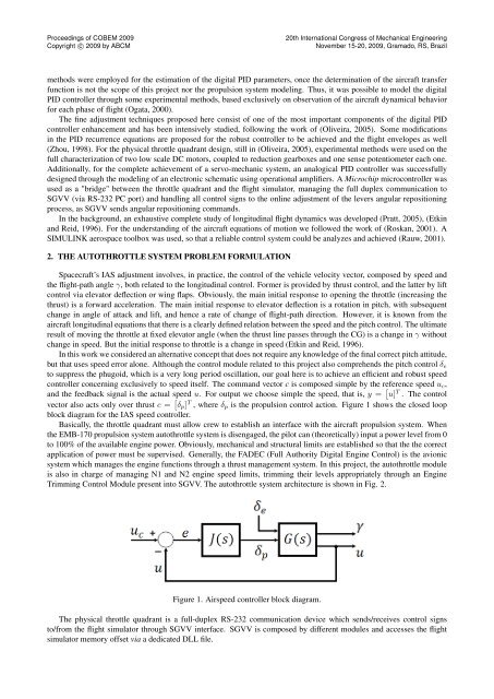
Proceedings of COBEM 2009Copyright c○ 2009 by ABCM20th International Congress of Mechanical EngineeringNovember 15-20, 2009, Gramado, RS, Brazilmethods were employed for the estimation of the digital PID parameters, once the determination of the aircraft transferfunction is not the scope of this project nor the propulsion <strong>system</strong> modeling. Thus, it was possible <strong>to</strong> model the digitalPID controller through some experimental methods, <strong>based</strong> exclusively on observation of the aircraft dynamical behaviorfor each phase of flight (Ogata, 2000).The fine adjustment techniques proposed here consist of one of the most important components of the digital PIDcontroller enhancement and has been intensively studied, following the work of (Oliveira, 2005). Some modificationsin the PID recurrence equations are proposed for the robust controller <strong>to</strong> be achieved and the flight envelopes as well(Zhou, 1998). For the physical throttle quadrant design, still in (Oliveira, 2005), experimental methods were used on thefull characterization of two low scale DC mo<strong>to</strong>rs, coupled <strong>to</strong> reduction gearboxes and one sense potentiometer each one.Additionally, for the complete achievement of a <strong>servo</strong>-mechanic <strong>system</strong>, an analogical PID controller was successfullydesigned through the modeling of an electronic schematic using operational amplifiers. A Microchip microcontroller wasused as a "bridge" between the throttle quadrant and the flight simula<strong>to</strong>r, managing the full duplex communication <strong>to</strong>SGVV (via RS-232 PC port) and handling all control signs <strong>to</strong> the online adjustment of the levers angular repositioningprocess, as SGVV sends angular repositioning commands.In the background, an exhaustive complete study of longitudinal flight dynamics was developed (Pratt, 2005), (Etkinand Reid, 1996). For the understanding of the aircraft equations of motion we followed the work of (Roskan, 2001). ASIMULINK aerospace <strong>to</strong>olbox was used, so that a reliable control <strong>system</strong> could be analyzes and achieved (Rauw, 2001).2. THE AUTOTHROTTLE SYSTEM PROBLEM FORMULATIONSpacecraft’s IAS adjustment involves, in practice, the control of the vehicle velocity vec<strong>to</strong>r, composed by speed andthe flight-path angle γ, both related <strong>to</strong> the longitudinal control. Former is provided by thrust control, and the latter by liftcontrol via eleva<strong>to</strong>r deflection or wing flaps. Obviously, the main initial response <strong>to</strong> opening the throttle (increasing thethrust) is a forward acceleration. The main initial response <strong>to</strong> eleva<strong>to</strong>r deflection is a rotation in pitch, with subsequentchange in angle of attack and lift, and hence a rate of change of flight-path direction. However, it is known from theaircraft longitudinal equations that there is a clearly defined relation between the speed and the pitch control. The ultimateresult of moving the throttle at fixed eleva<strong>to</strong>r angle (when the thrust line passes through the CG) is a change in γ withoutchange in speed. But the initial response <strong>to</strong> throttle is a change in speed (Etkin and Reid, 1996).In this work we considered an alternative concept that does not require any knowledge of the final correct pitch attitude,but that uses speed error alone. Although the control module related <strong>to</strong> this project also comprehends the pitch control δ e<strong>to</strong> suppress the phugoid, which is a very long period oscillation, our goal here is <strong>to</strong> achieve an efficient and robust speedcontroller concerning exclusively <strong>to</strong> speed itself. The command vec<strong>to</strong>r c is composed simple by the reference speed u c ,and the feedback signal is the actual speed u. For output we choose simple the speed, that is, y = [ u] T . The controlvec<strong>to</strong>r also acts only over thrust c = [ δ p ] T , where δ p is the propulsion control action. Figure 1 shows the closed loopblock diagram for the IAS speed controller.Basically, the throttle quadrant must allow crew <strong>to</strong> establish an interface with the aircraft propulsion <strong>system</strong>. Whenthe EMB-170 propulsion <strong>system</strong> au<strong>to</strong>throttle <strong>system</strong> is disengaged, the pilot can (theoretically) input a power level from 0<strong>to</strong> 100% of the available engine power. Obviously, mechanical and structural limits are established so that the the correctapplication of power must be supervised. Generally, the FADEC (Full Authority Digital Engine Control) is the avionic<strong>system</strong> which manages the engine functions through a thrust management <strong>system</strong>. In this project, the au<strong>to</strong>throttle moduleis also in charge of managing N1 and N2 engine speed limits, trimming their levels appropriately through an EngineTrimming Control Module present in<strong>to</strong> SGVV. The au<strong>to</strong>throttle <strong>system</strong> architecture is shown in Fig. 2.Figure 1. Airspeed controller block diagram.The physical throttle quadrant is a full-duplex RS-232 communication device which sends/receives control signs<strong>to</strong>/from the flight simula<strong>to</strong>r through SGVV interface. SGVV is composed by different modules and accesses the flightsimula<strong>to</strong>r memory offset via a dedicated DLL file.