mechatronic servo system applied to a simulated-based autothrottle ...
mechatronic servo system applied to a simulated-based autothrottle ...
mechatronic servo system applied to a simulated-based autothrottle ...
- No tags were found...

You also want an ePaper? Increase the reach of your titles
YUMPU automatically turns print PDFs into web optimized ePapers that Google loves.
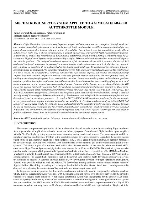
Proceedings of COBEM 2009Copyright c○ 2009 by ABCM20th International Congress of Mechanical EngineeringNovember 15-20, 2009, Gramado, RS, BrazilMECHATRONIC SERVO SYSTEM APPLIED TO A SIMULATED-BASEDAUTOTHROTTLE MODULERafael Coronel Bueno Sampaio, rafaelc@sc.usp.brMarcelo Becker, becker@sc.usp.brMechatronics Lab-SEM-EESC-USP, São Carlos, BrazilAbstract. Flight Simulation represents a very important support <strong>to</strong>ol on avionic <strong>system</strong>s conception, through which onecan emulate atmospheric phenomena as well as the aircraft itself. It also makes possible <strong>to</strong> experiment both flight mechanicaland dynamical behaviors with a high level of reliability. In practical terms, that contributes considerably <strong>to</strong>reduce project costs, once it allows the simulation, in ground, of many real scale aircraft flight circumstances/situations.In this work we propose the construction of a <strong>mechatronic</strong> au<strong>to</strong>throttle <strong>system</strong>, which is part of a <strong>simulated</strong>-<strong>based</strong> AFCS(Au<strong>to</strong>matic Flight Control System) project composed by a digital PID controller and an embedded microcontrolled physicalthrottle quadrant. The designed au<strong>to</strong>throttle <strong>system</strong> is a full au<strong>to</strong>nomous device which promotes the aircraft IAS(Indicated Air Speed) adjustment by means of the aircraft inertial acceleration management (calculated in three aircraftaxis). Initially we described all methods <strong>applied</strong> on the throttle quadrant design. We emphasized the DC mo<strong>to</strong>r full characterizationand an analogical PID controller modeling process, both using experimental techniques on the constructionof a <strong>servo</strong> <strong>system</strong>. As the digital PID controller calculates the right amount of power delivered <strong>to</strong> the <strong>simulated</strong> aircraftengines, it can be seen that the physical throttle levers also get their angular positions <strong>to</strong> the corresponding value, according<strong>to</strong> the aircraft engine power levels demanded at that time. In real au<strong>to</strong>throttle <strong>system</strong>s, on-line throttle quadrantangular reposition is a safety requirement <strong>to</strong> avoid catastrophic hazards/events due <strong>to</strong> overloading of engine structurallimits, preventing crew <strong>to</strong> demand erroneous levels of power. Experimental techniques were used on obtaining the DCmo<strong>to</strong>r full transfer function by acquiring both electrical and mechanical most important mo<strong>to</strong>r parameters. These methods<strong>to</strong>ok in<strong>to</strong> account some simplification hypotheses because the mo<strong>to</strong>r used in this work was a low scale device. Thethree PID parameters (proportional, derivative and integrative gains, respectively) were determined through a detailedinvestigation of the analogical PID controller circuitry. Furthermore, the analogical PID controller transfer function wasdetermined <strong>based</strong> on the related parameters. A complete MATLAB/SIMULINK model was developed for the <strong>mechatronic</strong><strong>servo</strong> <strong>system</strong> so that a complete analytical evaluation was established. Previous simulation analysis in SIMULINK hadshown very encouraging results for both DC mo<strong>to</strong>r and analogical PID controller transfer functions obtained throughthe use of experimental techniques and the predefined simplification assumptions. Excellent results were also achievedin practice. The <strong>mechatronic</strong> <strong>servo</strong> <strong>system</strong> designed responded very well <strong>to</strong> new reference entries for the lever angularposition adjustment in real time, as the controller demanded on-line new aircraft engine power.Keywords: AFCS, au<strong>to</strong>throttle <strong>system</strong>, DC mo<strong>to</strong>r characterization, digital controller, <strong>servo</strong> <strong>system</strong>.1. INTRODUCTIONThe correct computational application of the mathematical aircraft models results in outstanding flight simula<strong>to</strong>rsfor a huge number of applications related <strong>to</strong> aerospace industry projects. Ground-<strong>based</strong> flight simula<strong>to</strong>rs provide pilotswith the "feel" of flight by using a combination of simula<strong>to</strong>r motions and visual images. The more sophisticated flightsimula<strong>to</strong>rs provide six degrees of freedom <strong>to</strong> the simula<strong>to</strong>r cockpit, driven by computers, <strong>to</strong> produce the desired motion<strong>based</strong> on the so-called aircraft equations of motion (Rolfe, 1983). Those ground-<strong>based</strong> flight trainers perfectly reproducethe aircraft cockpit, allowing crew <strong>to</strong> interact with the embedded avionic <strong>system</strong>s, just as they were handling real avionic<strong>system</strong>s. This study is part of a previous work which aims the construction of low-cost full <strong>simulated</strong>-<strong>based</strong> AFCS(Au<strong>to</strong>matic Flight Control System) and physical avionic <strong>system</strong>s for the Embraer EMB-170. These avionic <strong>system</strong>s can beattached <strong>to</strong> the computer which generates the dynamics of such aircraft, so that it is possible <strong>to</strong> offer MMI (Man MachineInterfaces), similar <strong>to</strong> the real aircraft ones (Sampaio, 2008). In that work, Microsoft Flight Simula<strong>to</strong>r 2004 was used <strong>to</strong>generate almost 1400 aircraft flight parameters such as the aircraft state vec<strong>to</strong>r of flight derivatives necessary on solvingthe equations of motion. A software interface named SGVV (Portuguese acronym for Flight Parameters ManagementSystem) was specially written <strong>to</strong> read and write MSFS 2004 offset memory addresses which contains current values offlight variables. The ability of reading and writing on the simulation is what allows closed loop control <strong>system</strong>s <strong>to</strong> bedesigned, thus allowing the construction of low cost real-time avionics <strong>system</strong>s as well.In the present work we propose the design of a <strong>mechatronic</strong> au<strong>to</strong>throttle <strong>system</strong>, composed by a throttle quadrantwhich, likewise in real aircrafts, provides pilot with the visual precise and current level of power delivered <strong>to</strong> the aircraft’sengines for a specific flight condition. A full digital au<strong>to</strong>throttle <strong>system</strong> was implemented for the aircraft’s IAS (IndicatedAir Speed) adjustment by means of the aircraft inertial acceleration management. The digital au<strong>to</strong>throttle <strong>system</strong>was embedded in<strong>to</strong> the AFCS module in SGVV. Heuristic methods were used <strong>to</strong> the implementation of the digital PIDrecurrence equations and they <strong>based</strong> on Tustin approximation and backward difference approximation. Ziegler-Nichols’
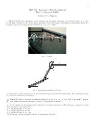
Proceedings of COBEM 2009Copyright c○ 2009 by ABCM20th International Congress of Mechanical EngineeringNovember 15-20, 2009, Gramado, RS, Brazilmethods were employed for the estimation of the digital PID parameters, once the determination of the aircraft transferfunction is not the scope of this project nor the propulsion <strong>system</strong> modeling. Thus, it was possible <strong>to</strong> model the digitalPID controller through some experimental methods, <strong>based</strong> exclusively on observation of the aircraft dynamical behaviorfor each phase of flight (Ogata, 2000).The fine adjustment techniques proposed here consist of one of the most important components of the digital PIDcontroller enhancement and has been intensively studied, following the work of (Oliveira, 2005). Some modificationsin the PID recurrence equations are proposed for the robust controller <strong>to</strong> be achieved and the flight envelopes as well(Zhou, 1998). For the physical throttle quadrant design, still in (Oliveira, 2005), experimental methods were used on thefull characterization of two low scale DC mo<strong>to</strong>rs, coupled <strong>to</strong> reduction gearboxes and one sense potentiometer each one.Additionally, for the complete achievement of a <strong>servo</strong>-mechanic <strong>system</strong>, an analogical PID controller was successfullydesigned through the modeling of an electronic schematic using operational amplifiers. A Microchip microcontroller wasused as a "bridge" between the throttle quadrant and the flight simula<strong>to</strong>r, managing the full duplex communication <strong>to</strong>SGVV (via RS-232 PC port) and handling all control signs <strong>to</strong> the online adjustment of the levers angular repositioningprocess, as SGVV sends angular repositioning commands.In the background, an exhaustive complete study of longitudinal flight dynamics was developed (Pratt, 2005), (Etkinand Reid, 1996). For the understanding of the aircraft equations of motion we followed the work of (Roskan, 2001). ASIMULINK aerospace <strong>to</strong>olbox was used, so that a reliable control <strong>system</strong> could be analyzes and achieved (Rauw, 2001).2. THE AUTOTHROTTLE SYSTEM PROBLEM FORMULATIONSpacecraft’s IAS adjustment involves, in practice, the control of the vehicle velocity vec<strong>to</strong>r, composed by speed andthe flight-path angle γ, both related <strong>to</strong> the longitudinal control. Former is provided by thrust control, and the latter by liftcontrol via eleva<strong>to</strong>r deflection or wing flaps. Obviously, the main initial response <strong>to</strong> opening the throttle (increasing thethrust) is a forward acceleration. The main initial response <strong>to</strong> eleva<strong>to</strong>r deflection is a rotation in pitch, with subsequentchange in angle of attack and lift, and hence a rate of change of flight-path direction. However, it is known from theaircraft longitudinal equations that there is a clearly defined relation between the speed and the pitch control. The ultimateresult of moving the throttle at fixed eleva<strong>to</strong>r angle (when the thrust line passes through the CG) is a change in γ withoutchange in speed. But the initial response <strong>to</strong> throttle is a change in speed (Etkin and Reid, 1996).In this work we considered an alternative concept that does not require any knowledge of the final correct pitch attitude,but that uses speed error alone. Although the control module related <strong>to</strong> this project also comprehends the pitch control δ e<strong>to</strong> suppress the phugoid, which is a very long period oscillation, our goal here is <strong>to</strong> achieve an efficient and robust speedcontroller concerning exclusively <strong>to</strong> speed itself. The command vec<strong>to</strong>r c is composed simple by the reference speed u c ,and the feedback signal is the actual speed u. For output we choose simple the speed, that is, y = [ u] T . The controlvec<strong>to</strong>r also acts only over thrust c = [ δ p ] T , where δ p is the propulsion control action. Figure 1 shows the closed loopblock diagram for the IAS speed controller.Basically, the throttle quadrant must allow crew <strong>to</strong> establish an interface with the aircraft propulsion <strong>system</strong>. Whenthe EMB-170 propulsion <strong>system</strong> au<strong>to</strong>throttle <strong>system</strong> is disengaged, the pilot can (theoretically) input a power level from 0<strong>to</strong> 100% of the available engine power. Obviously, mechanical and structural limits are established so that the the correctapplication of power must be supervised. Generally, the FADEC (Full Authority Digital Engine Control) is the avionic<strong>system</strong> which manages the engine functions through a thrust management <strong>system</strong>. In this project, the au<strong>to</strong>throttle moduleis also in charge of managing N1 and N2 engine speed limits, trimming their levels appropriately through an EngineTrimming Control Module present in<strong>to</strong> SGVV. The au<strong>to</strong>throttle <strong>system</strong> architecture is shown in Fig. 2.Figure 1. Airspeed controller block diagram.The physical throttle quadrant is a full-duplex RS-232 communication device which sends/receives control signs<strong>to</strong>/from the flight simula<strong>to</strong>r through SGVV interface. SGVV is composed by different modules and accesses the flightsimula<strong>to</strong>r memory offset via a dedicated DLL file.
Proceedings of COBEM 2009Copyright c○ 2009 by ABCM20th International Congress of Mechanical EngineeringNovember 15-20, 2009, Gramado, RS, BrazilFigure 2. Architecture of the au<strong>to</strong>throttle <strong>system</strong> and the SGVV interface schematics.3. IAS ADJUSTMENT AND THE ACCELERATION MANAGEMENT PROBLEM FORMULATIONThe IAS control problem is defined as the determination of the right amount of power provided <strong>to</strong> the aircraft enginethat generates a given set of desired accelerations specified by a flight control law which transfers algorithms’ commands(which are merged in<strong>to</strong> the digital PID module) given by a defined acceleration envelope. As this work is related <strong>to</strong> theconstruction of a brand new AFCS, it is reasonable <strong>to</strong> assume that determining the referred above aircraft accelerationenvelope is also needed, prior <strong>to</strong> the implementation of PID routines. Some empiric assumptions were necessary in order<strong>to</strong> get this process started (Pratt, 2005).3.1 Acceleration Envelope DeterminationFlight essays were run with the aircraft flying in cruise steady mode in order <strong>to</strong> study and then obtain the curve that bestrepresents the aircraft acceleration envelope for that phase of flight. It was considered that the aircraft current accelerationshould be given as a direct function of the IAS error, that is, there is a proper value for the aircraft acceleration for eachdifference between the target speed and the current speed. Furthermore, the aircraft acceleration envelope should respectthe human body acceleration limits. In order <strong>to</strong> simplify the analysis, a priori, it was assumed that aircraft accelerationshould not exceed 1G, that is, the acceleration envelope should be trimmed at around 9, 8m/s 2 (32, 15ft/s 2 ). The aircraftacceleration envelope determined can be seen from Fig. 3. As it was expected, the curve is approximately linear. Thisstage is very important once the flight envelope determined here will be used as benchmark for the digital PID controllerdesign. By visually inspecting the interpolated curve from Fig. 3, it is possible <strong>to</strong> obtain the angular coefficient of thefunction, so that the target acceleration can be given by:acel target ≈ 0, 049 · delta vel (1)Where delta vel is equivalent <strong>to</strong> the difference between the target speed and the current speed.Digital PID controller will take Eq. (1) <strong>to</strong> calculate the best control action as the reference value <strong>to</strong> the engine powermanagement. Engine power management is executed by the correction on the the throttle levers position in the <strong>simulated</strong>aircraft. It means that the virtual levers change their angular position, as the digital PID controller calculates the bestpower decreasing or increasing rates. Therefore, PID controller manages the aircraft inertial acceleration through anoutput control signal δ p , which actually acts over the engine by means of controlling the lever angular position on thevirtual throttle quadrant. In practice, controller must provide flight simula<strong>to</strong>r with binary incremental/decremental valuesin a range from 0 <strong>to</strong> 1024 (10 bits), which will affect the angular lever position and so both engine’s power.3.2 Digital PID Controller Recurrence EquationsThe digital PID controller implemented in this work consists on an algorithm <strong>based</strong> on the recurrence equationsproposed in (Oliveira, 2005). These algorithms consider the positional form with backward difference approximation <strong>to</strong>the integrative term (I) and Tustin approximation <strong>to</strong> derivative term (D), whose control laws can be respectively represented
Proceedings of COBEM 2009Copyright c○ 2009 by ABCM20th International Congress of Mechanical EngineeringNovember 15-20, 2009, Gramado, RS, BrazilFigure 3. Relationship between target acceleration and difference between current speed and required speed.by:P (k) = K p [βr(k) − y(k)]; (2)I(k) = I(k − 1) + K pTT ie(k − 1) (3)D(k) = 2T d − T N2T d + T N D(k − 1) + 2K pT d N(y(k) − y(k − 1)) (4)2T d + T NP (k), I(k) and D(k) correspond, respectively, <strong>to</strong> proportional, integrative and derivative control signals. K p is theproportional gain, T i is the integrative time and T d is the derivative time. r(k) is the reference signal (which representsthe target acceleration), y(k) is the output signal (control signal, which represents the increasing or decreasing rate onlever position) and e(k) is the error. T is the sample rate of data acquisition, N is one important parameter that optimizesderivative action and assures the controller normal operation. For the proportional action, a fine tuning parameter β is alsoemployed (Oliveira, 2005), acting over the output signal.3.3 Heuristic Methods for Reducing the Effects of Zeros and Poles in Controller PerformanceThe determination of K p , T i and T d followed the 2nd Ziegler-Nichols method proposed by (Ogata, 2000), since thisproject does not aim <strong>to</strong> determine the aircraft exact transfer function (neither the propulsion <strong>system</strong> mathematical model).Once both K cr and P cr are found, it is possible <strong>to</strong> determine the values of K p , T i and T d by Ziegler-Nichols look-upequations (Ogata, 2000). It turns out necessary <strong>to</strong> analyze the final PID equation in order <strong>to</strong> propose some changes on it,as well as the use of some digital filters. The PID equation, following Ziegler-Nichols methods, can be written as follows:G c (s) = 0, 075K cr P cr(s + 4P cr) 2sIn first analysis, it is necessary <strong>to</strong> pay close attention <strong>to</strong> Eq. (5). The equation has one pole at the origin and a doublezero in s = −4P cr. This contributes <strong>to</strong> the elimination of the stationary state error. However, it can still be observed fromEq. (5) that the greater the error becomes, the grater becomes the output signal (control signal). It certainly causes thethrottle actua<strong>to</strong>rs <strong>to</strong> be unstable which, by the way, becomes the <strong>system</strong> also unstable. At best, it takes much longer <strong>to</strong>stabilize the <strong>system</strong>, causing undesirable overshoot rates.The reset-windup effect was prevented by implementing an anti-reset-windup filter, which acts over the integrativeband (Oliveira, 2005). The filter works under the following condition:∆u i (k) = 0, if |e(k)| ≥ e max (6)(5)
Proceedings of COBEM 2009Copyright c○ 2009 by ABCM20th International Congress of Mechanical EngineeringNovember 15-20, 2009, Gramado, RS, BrazilThe term u i (k) refers <strong>to</strong> integrative band contribution on PID controller and e max is maximum desired error, whichis experimentally determined by observing and proposes the canceling of integrative contribution when it reaches themaximum value for the error, previously set.As for the derivative action, it also can present values that contribute directly <strong>to</strong> the <strong>system</strong> instability in some circumstances.In example, derivative band introduces an uncontrollable gain increase at hight frequencies. This is called quickderivative effect. As it can be seen from the right hand of Eq. (5), derivative term presents one pole at the infinite. Thatproves the above-mentioned instability at high frequencies. Once an undefined increasing in frequency occurs, derivativegain also increases and then makes the <strong>system</strong> out of control. The filter <strong>applied</strong> in this case aims <strong>to</strong> add one pole <strong>to</strong> thederivative contribution on the general PID action. That results in the following derivative term:D(k) = K pT d s1 + T dN s (7)Where N is a constant that assures the realizability of the controller when operating at high frequencies. Values of Nof 3 ≤ N ≤ 20 are usually adopted (Oliveira, 2005).As proposed in (Oliveira, 2005), is also convenient <strong>to</strong> introduce a proportional band fine tuning coefficient β, in<strong>to</strong> theproportional action, as it is shown in Eq. (2). Indeed, flight tests showed very good results especially on eliminating thestationary state error. Improving on transi<strong>to</strong>ry response was also successfully achieved.Although it is known that proportional band fine adjustment (by the use of β) itself eventually results in a goodperformance, an au<strong>to</strong>throttle <strong>system</strong> demands a very precise action from the controller. Therefore, as it concerns <strong>to</strong> anAFCS application, it is strongly recommended that all three enhancement methods are simultaneously employed, in order<strong>to</strong> achieve an improvement of the final responses.After this detailed analysis, 2nd Ziegler-Nichols method was <strong>applied</strong> in order <strong>to</strong> obtain the digital PID parameters.Aircraft responds distinctly for each phases of flight as its dynamics changes for each flight situations. Hence, PID willassume a different set of values <strong>to</strong> each one. However, cruise steady flight was taken as the benchmark scenario for thePID parameters calculation. Thus, altitude was set constant as the aircraft was requested <strong>to</strong> hold speed at 250 Kts. Valuesof T i and T d were set <strong>to</strong> infinite and zero respectively. At a certain point of the flight test the aircraft inertial accelerationwas expected <strong>to</strong> present an oscilla<strong>to</strong>ry behavior, as K cr slowly started raising from zero. At a value of K cr ≈ 284,acceleration presented a maintained oscilla<strong>to</strong>ry behavior, and a P cr ≈ 23s (signal period) was noted. Applying the valuesof K cr and P cr <strong>to</strong> the Ziegler-Nichols lookup equations, it was found a proportional gain K p ≈ 170, an integrative timeT i ≈ 11 and a derivative time T d ≈ 2, 87.4. THE THROTTLE QUADRANT ASSEMBLYThe throttle quadrant designed for the au<strong>to</strong>throttle <strong>system</strong> consists basically on a <strong>servo</strong> <strong>system</strong>, composed by twolow scale and low current consumption DC mo<strong>to</strong>rs, an analogical PID controller and linear potentiometers whose signalsare feedback. Each aircraft’s engine power lever brings also additional linear potentiometers in their respective bot<strong>to</strong>ms,through which both levers were coupled <strong>to</strong> the DC mo<strong>to</strong>r shafts. These potentiometer send throttle signals <strong>to</strong> the microcontrollerand the last one, in turn, sends increase/decrease thrust commands <strong>to</strong> the flight simula<strong>to</strong>r through SGVV. On theother hand, digital PID controller calculates appropriated aircraft acceleration envelopes and sends (on-line) new entriesof the lever angular position <strong>to</strong> the microcontroller which, by the way, sends equivalent commands <strong>to</strong> the analogical PIDcontroller for both levers’ new angular positions. The following sections describe the analogical PID controller design,the full characterization of both DC mo<strong>to</strong>rs and the microcontrolled signal conditioning <strong>to</strong> the management of the throttlequadrant.4.1 The Analogical PID Controller Design and Parameters EstimationAn analogical PID controller was designed <strong>to</strong> achieve a <strong>servo</strong>mechanism <strong>to</strong> the throttle quadrant. In order <strong>to</strong> analyzethe control actions, PID controller’s transfer functions was found <strong>based</strong> on the electronic schematics seen in Fig. 4, and isrepresented by the following equation:G(s) = R 2 R 6 R 8− R 10 1·R 1 R 5 R 7 R 9 1 + R 10 C 1 s − R 11C 2 s (8)In practical terms, the three PID controller parameters can be determined by some discrete electronic componentsrelations and combinations. In this case, proportional gain K p ≈ R8R 7, integrative time T i ≈ R 9 C 1 and derivative timeT d ≈ R 11 C 2 . A SIMULINK model was set up, so that diverse values for the discrete components could be tried outin order <strong>to</strong> achieve an appropriated response from the controller. Thus, <strong>based</strong> on this model, the controller respondedsatisfac<strong>to</strong>rily <strong>to</strong> values for proportional gain K p = 10, integrative time T i = 0.01 and derivative time T d = 0.1.
Proceedings of COBEM 2009Copyright c○ 2009 by ABCM20th International Congress of Mechanical EngineeringNovember 15-20, 2009, Gramado, RS, BrazilFigure 4. Electronic schematics for the analogical PID controller employed on the DC mo<strong>to</strong>r shaft angular position.4.2 The DC Mo<strong>to</strong>r Full Characterization ProcessBoth DC mo<strong>to</strong>rs used in the throttle quadrant are low scale and low current consumption mo<strong>to</strong>r drives each one coupled<strong>to</strong> a reduction gearbox. There is a linear potentiometer also coupled <strong>to</strong> the mo<strong>to</strong>r shaft which works as a voltage sensorfor the feedback control <strong>system</strong>. Thus, it turns the whole assembly <strong>to</strong> a <strong>servo</strong> <strong>system</strong>. DC mo<strong>to</strong>r full characterizationwas <strong>based</strong> on practical labora<strong>to</strong>ry experiments witch allowed us <strong>to</strong> obtain a very reliable transfer function <strong>to</strong> describe themo<strong>to</strong>r dynamics, from the determination of both mechanical and electrical related parameters. Following the methodsdescribed by (Oliveira, 2005), the DC mo<strong>to</strong>r’s transfer function can be represented by the following:M(s) =k ms[T m s + 1](9)Where k m and T m are defined as the DC mo<strong>to</strong>r both gain constant and time constant respectively. These constants arerespectively defined by the following equations:k m =k tR a k b + k cem k t(10)T m =R a JR a k b + k cem k t(11)Where k b is the EMF (Electromotive Force) constant, R a is the coil resistance, k cem is the back EMF force, k t isthe <strong>to</strong>rque constant and J is the shaft moment of inertia. The parameter denoted as L a is the coil inductance and it wasneglected since the DC mo<strong>to</strong>r is a very small scale device (Oliveira, 2005). All DC mo<strong>to</strong>r parameters were determinedfollowing the previous referenced methods and are listed in Tab. 1.Replacing the values of each parameter from Tab. 1 in Eq. (10) and (11), the following DC mo<strong>to</strong>r transfer function isobtained:M(s) =21, 04s[0.0017s + 1]Another important parameter which must be taken in<strong>to</strong> account is the gearbox reduction transfer function in order <strong>to</strong>insert it in<strong>to</strong> the closed loop control. As the reduction relation is of about 100:6, the gearbox transfer function can begiven as a gain, represented by an attenuation which can be given by n, as follows:n ≈ 60 · 10 −3 (13)(12)
Proceedings of COBEM 2009Copyright c○ 2009 by ABCM20th International Congress of Mechanical EngineeringNovember 15-20, 2009, Gramado, RS, BrazilTable 1. DC mo<strong>to</strong>r electromechanical parameters.Parameter Value DimensionR a 14 Ωk cem 0,0411 -k t 0,0411 -−9 Nms2J 240 ·10radk b 18,83 ·10 −6 -The feedback linear potentiometer must be also included as part of the final plant. In Laplace domain, the linearpotentiometer transfer function can be expressed by:P (s) = α s 2 (14)Where α is the angular coefficient of the potentiometer output voltage curve versus time.Since all <strong>servo</strong> <strong>system</strong> components were modeled, it is now possible <strong>to</strong> obtain a full closed loop schematics, in order<strong>to</strong> analyze its responses <strong>to</strong> input signals. Figure 5 shows the <strong>servo</strong> <strong>system</strong> schematics including analogical PID controller,DC mo<strong>to</strong>r, reduction gearbox and linear feedback potentiometer transfer functions.Figure 5. Throttle quadrant <strong>servo</strong> <strong>system</strong> schematics.4.3 Microcontrolled DC Mo<strong>to</strong>r Shaft Angular Position ManagementDC mo<strong>to</strong>r shaft angular position control primarily depends on a reference signal incoming from SGVV digital controlmodule. However, the module only calculates the right position of the throttle levers <strong>based</strong> on the current amount ofpower requested <strong>to</strong> the aircraft engines. It turns out important <strong>to</strong> send this position <strong>to</strong> the physical lever, which is achievedby the PC RS-232 communication port, where SGVV writes the RS-232 bus with proper commands addressed <strong>to</strong> themicrocontroller. The last one, by the way, must provide analogical PID controller with proper reference signals <strong>to</strong> thecorrect shaft angular adjustment. PWM (Pulse Width Modulation) was used <strong>to</strong> vary the reference tension values <strong>to</strong> thePID controller, since it its more convenient <strong>to</strong> the microcontroller <strong>to</strong> work with digital signal processing. The followingtransfer function was obtained <strong>to</strong> the precise calculation of the reference signal <strong>to</strong> the angular shaft positioning process:P s ≈ 10, 38 · 10 −3 · P ms + 650 (15)Where P s is the PWM duty cycle value and P ms is the lever position calculated by SGVV digital control module.The PWM duty cycle variation will result in an analogical signal (electrical tension), which is properly conditioned as areference value <strong>to</strong> the PID controller.
Proceedings of COBEM 2009Copyright c○ 2009 by ABCM20th International Congress of Mechanical EngineeringNovember 15-20, 2009, Gramado, RS, Brazil5. AUTOTHROTTLE SYSTEM IMPLEMENTATION AND PERFORMANCE EVALUATIONSeveral hours of flight tests have shown that the designed au<strong>to</strong>throttle <strong>system</strong> has successfully achieved compliancewith the IAS control aims. The digital PID controller has produced acceleration responses which follows reference signalswith minimum delay, which will consequently influence the IAS curve. Figure 6 shows the IAS response <strong>to</strong> a 293 Ktsreference speed, produced by the digital PID controller. It is clear from the figure that IAS adjustment has producedacceptable overshoot levels as well as excellent transi<strong>to</strong>ry responses. It reached an average overshoot level of 0,6%and stationary response values around 0,1%, which means that the controller fully satisfies the initial IAS adjustmen<strong>to</strong>bjectives (Ogata, 2000). Additional flight tests were run in order <strong>to</strong> re-check the above-mentioned results. They havereproduced the same levels of accuracy, which allows <strong>to</strong> consider the heuristic methods proposed here, so that an optimaland robust controller could be achieved.Figure 6. Indicated air speed response after the digital PID controller fine adjustment.The physical throttle quadrant has also presented very good results. Figure 7 shows the DC mo<strong>to</strong>r shaft angularresponse θ(s) <strong>to</strong> a step input reference signal. That means that the DC mo<strong>to</strong>r full characterization process has successfullyproduced a very reliable model for the device, so that its transfer function complies <strong>to</strong> the real model.Figure 7. DC mo<strong>to</strong>r angular position response <strong>to</strong> step input.The analogical PID controller designed has also produced very satisfac<strong>to</strong>ry results. Figure 8 shows the controller
Proceedings of COBEM 2009Copyright c○ 2009 by ABCM20th International Congress of Mechanical EngineeringNovember 15-20, 2009, Gramado, RS, Brazilresponse <strong>to</strong> a step input reference signal. It can be observed that it has achieved an error around 1.01%, which fullysatisfies the initial control demands. Figure 9 brings the final plant response <strong>to</strong> a step input which, in practice, is the onlinereference signal incoming from the microcontroller. The plant includes the DC mo<strong>to</strong>r model, reduction gearbox gain,analogical PID controller and sensing feedback linear potentiometer. As it can be noted the <strong>servo</strong> <strong>system</strong> model responsealso fully satisfies the control demands, producing a very quick and precise angular throttle lever on-line reposition which,in practice, can be verified in flight essays, while SGVV calculates new aircraft acceleration levels.Figure 8. Analogical PID controller response <strong>to</strong> a 5V step input signal.Figure 9. Final plant response <strong>to</strong> a 5V step input signal.The physical throttle quadrant is shown in Fig. 10. It can be seen the EMB-170 control panel (A) whereas in the leftbot<strong>to</strong>m corner the virtual throttle quadrant is noted. While SGVV au<strong>to</strong>throttle module (through the digital PID controller)calculates new engine power levels by repositioning both virtual levers, physical levers also have their angular positionreadjusted (B), so that the pilot can accurately and precisely visualize the power level requested <strong>to</strong> the aircraft’s engineson-line.
Proceedings of COBEM 2009Copyright c○ 2009 by ABCM20th International Congress of Mechanical EngineeringNovember 15-20, 2009, Gramado, RS, BrazilFigure 10. Au<strong>to</strong>throttle <strong>system</strong> pro<strong>to</strong>type in running mode.6. CONCLUSIONSSimulation flight tests have shown very satisfac<strong>to</strong>ry results on the digital PID controller design, through the proposedmethods. The insertion of the fine adjustment parameters on both proportional (β) and derivative (N) bands was extremelyimportant <strong>to</strong> the controller efficiency achievement. Simulation plots confirmed that the methodology employed in thiswork results a more robust control <strong>system</strong> for the inertial acceleration stabilization problem than conventional classicdesign techniques. The digital au<strong>to</strong>throttle <strong>system</strong> presented very satisfac<strong>to</strong>ry results in all circumstances, even when inthe presence of high frequencies noise conditions, for instance, severe wind shear conditions. The <strong>mechatronic</strong> throttlequadrant was successfully designed. Experimental techniques on full characterization of the DC mo<strong>to</strong>r proved <strong>to</strong> beefficient. The analogical PID controller design process has also been successfully developed, since the initial aims werereached.Future works includes the incorporation of an au<strong>to</strong>nomous flight phase change detection module, considering anintelligent self-reconfigurable adaptive controller, by using Kalman estima<strong>to</strong>rs, which will au<strong>to</strong>nomously calculate thecontroller parameters for each flight situation.7. ACKNOWLEDGEMENTSThe authors gratefully acknowledge the contribution of Engineer Thiago Cestari from Embraer for the crucial technicalaid concerning <strong>to</strong> the validation of many results from the <strong>simulated</strong> aircraft, such as the aircraft envelopes and theau<strong>to</strong>throttle <strong>system</strong> as well.8. REFERENCESEtkin, B.; Reid, L. D., 1996, Dynamics of Flight, Stability and Control, 3rd ed., JOHN WILEY SONS, INC., New York,USA.Ogata, K., 2000, Engenharia de Controle Moderno, 3rd ed., LTC, Rio de Janeiro, Brazil.Zhou, K., 1998, Essentials of Robust Control, Prentice Hall, Upper Saddle River, USA.Pratt, R. W., 2005, Flight Control Systems, Volume 184, AIAA, Cambridge, UK.Rauw, Marc, 2001, FDC 1.2, A Simulink Toolbox for Flight Dynamics and Control Analysis, Second Edition, Delft Universityof Technology - Faculty of Aerospace Engineering Disciplinary Group for Stability and Control, Netherlands.Rolfe, J. M.; Staples, K. J., 1986, Flight simulation, Cambridge University Press, New York, USA.Roskan, Jan, 2001, Airplane Flight Dynamics And Au<strong>to</strong>matic Flight Controls, Part I, DAR Corporation, Lawrence/Kansas,USA.Sampaio, R. C. B., 2008, Avionic <strong>system</strong>s development <strong>based</strong> on flight simula<strong>to</strong>r, Proceedings of XVI SIICUSP, Ed. USP,São Paulo, Brazil.9. RESPONSIBILITY NOTICEThe authors are the only responsible for the printed material included in this paper