High frequency inverter ACO5000 by ACOMEL USER MANUAL
High frequency inverter ACO5000 by ACOMEL USER MANUAL
High frequency inverter ACO5000 by ACOMEL USER MANUAL

Create successful ePaper yourself
Turn your PDF publications into a flip-book with our unique Google optimized e-Paper software.
DANAHER MOTION S.A.<br />
9<br />
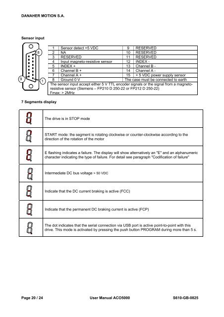
Sensor input<br />
8<br />
1<br />
7 Segments display<br />
1 Sensor detect +5 VDC 9 RESERVED<br />
2 NA 10 RESERVED<br />
3 RESERVED 11 RESERVED<br />
4 Input magneto-resistive sensor 12 INDEX -<br />
5 INDEX + 13 Channel B -<br />
6 Channel B + 14 Channel A -<br />
7 Channel A + 15 + 5 VDC power supply sensor<br />
8 Ground 0 V The case must be connected to earth<br />
The sensor input accept either 5 V TTL encoder signals or the signal from a magnetoresistive<br />
sensor (Siemens – FP210 D 250-22 or FP212 D 250-22)<br />
Fmax: > 2MHz<br />
The drive is in STOP mode<br />
START mode: the segment is rotating clockwise or counter-clockwise according to the<br />
direction of the rotation of the motor<br />
E flashing indicates a failure. The display will show alternatively an "E" and an alphanumeric<br />
character indicating the type of failure. For detail see paragraph "Codification of failure"<br />
Intermediate DC bus voltage > 50 VDC<br />
Indicate that the DC current braking is active (FCC)<br />
Indicate that the permanent DC braking current is active (FCP)<br />
The dot indicates that the serial connection via USB port is active point-to-point with this<br />
drive. This mode is activated <strong>by</strong> pressing the push button PROGRAM during more than 5 s.<br />
Page 20 / 24 User Manual <strong>ACO5000</strong> S610-GB-0825