Steel Plate Shear Wall Design - SEAoT
Steel Plate Shear Wall Design - SEAoT
Steel Plate Shear Wall Design - SEAoT
- No tags were found...

You also want an ePaper? Increase the reach of your titles
YUMPU automatically turns print PDFs into web optimized ePapers that Google loves.
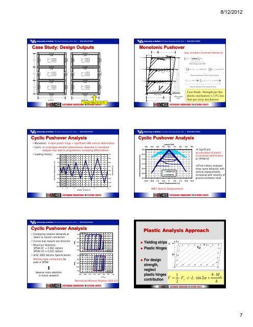
s n ss n s8/12/2012Case Study: <strong>Design</strong> Outputs10 ft10 ft10 ftW16x40W24x62 W18x x50(0.96)(0.91 1)(0.99)W16x36(0.88)tplate = 0.036 inS = 19.69 inAstrip = 0.72 in 2W12x22(0.98)tplate = 0.059 inS = 19.69 inAstrip = 1.17 in 2W12x19(0.92)tplate = 0.072 inS = 19.69 inAstrip = 1.42 in 2W24x62(0.91)20 ftSPSW-IDW24x62 W18x x50 W16x40(0.99) (0.91 1) (0.96)W16x89W24x146 W18x x76(0.98)(0.99 9)(0.96)W18x76(0.99)tplate = 0.036 inS = 19.69 inAstrip = 0.72 in 2W14x61(0.99)tplate = 0.059 inS = 19.69 inAstrip = 1.17 in 2W12x45(0.95)tplate = 0.072 inS = 19.69 inAstrip = 1.42 in 2W24x117(0.98)20 ftSPSW-CDW24x146 W18x x76 W16x89(0.96) (0.99 9) (0.98)<strong>Design</strong> HBEs for wL 2 /4Monotonic PushoverVi+2Vi+1ViθΔi+2Δi+1ΔiL1L2L 1 θ / L 2 +θPlastic HingeLpαωbbL2L1ωcL 1 θ / L 2 +θHiHi+1Hi+2Strips remainedelasticSway and Beam Combined Mechanismn∑ViHi=1n1+ ∑ 2+i=1Fyp⎛ L p ⎜i = 2⎝ L p − L1tw1FypLp( t wi⎞⎟∑ M⎠ i=0pbiPlastic Hinge on the HBEsL21∑ 2−twi+ 1 )sin (2α) H i − FyptwiL1sin (2α)i=1Horizontal component of the strip yield forcesn s2 L1cos α + ∑ F2i=1yp( twiL2−twi+1Lp)2cosVertical component of the strip yield forcesCase Study: Strength per thisplastic mechanism is 13% lessthan per sway mechanismαL12H iCyclic Pushover Analysis• Monotonic: in-span plastic hinge + significant HBE vertical deformation• Cyclic: to investigate whether phenomenon observed in monotonicanalysis may lead to progressively increasing deformations• Loading history: 14.44%(in)Top Floor Displacement, Δ10.87.23.60-3.6-7.2-10.83%2%1%0%-1%-2%-3%Lateral Drift (%)Cyclic Pushover Analysiscement (in) .Vertical Displac0.0-0.5-1.0-1.5 15-2.0-2.5-3.0Lateral Drift-4% -3% -2% -1% 0% 1% 2% 3% 4%SPSW-CDSPSW-ID-14.4 -10.8 -7.2 -3.6 0 3.6 7.2 10.8 14.4Lateral Displacement (in) Significantaccumulation of plasticincremental deformationon SPSW-IDTime history analysesshow same behavior, withvertical displacementsincreasing with severity ofground excitation level-14.41 2 3 4 5 6Number of Cycles, N-4%HBE3 Vertical DisplacementsCyclic Pushover Analysis• Comparing rotation demands atbeam to column connection• Curves bias toward one direction• Maximum Rotations:SPSW-ID = 0.062 radiansSPSW-CD = 0.032 radians• AISC 2005 Seismic Specifications:Ordinary-type connections beused in SPSWdeserve more attentionin future researchM/M pM/M p1.00.50.0-0.5-1.01.00.50.0-0.5SPSW-IDSPSW-CDHBE2-1.0HBE2-2.5 -2.0 -1.5 -1.0 -0.5 0.0 0.5 1.0θ/θ 0.03Normalized Moment Rotation (θ/0.03)Plastic Analysis Approach• Yielding strips• Plastic Hinges• For designstrength,neglectplastic hingescontribution14 ⋅ MV = ⋅ Fy⋅t⋅ L ⋅sin 2α+2hp7