For DMAE Process Description Click Here - ippe.com
For DMAE Process Description Click Here - ippe.com
For DMAE Process Description Click Here - ippe.com
- No tags were found...

You also want an ePaper? Increase the reach of your titles
YUMPU automatically turns print PDFs into web optimized ePapers that Google loves.
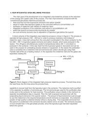
International <strong>Process</strong> PlantsHamilton Business Center17A Marlen DriveHamilton, NJ 08691Phone : +1(609) 586-8004Fax : +1 (609) 586-0002<strong>DMAE</strong> PLANT PROCESS DESCRIPTIONThe purpose of the <strong>DMAE</strong> plant is to react Dimethylamine (DMA) with Ethylene Oxide (EO), toproduce dimethylaminoethanol (<strong>DMAE</strong>) as a saleable product in either bulk or drum packaging.In addition Diethylamine (DEA) can be reacted with EO making Diethylaminoethanol (DEAE) inthe same plant. The current capacity of the plant is approximately 7000 tpa. In recent years theplant has been dedicated to <strong>DMAE</strong> production. The <strong>DMAE</strong> plant was built in 1974The <strong>DMAE</strong> Plant is an open, steel-frame structure, with Kennedy grating floors. It is positionedon a concrete base that drains in to an effluent collection system.1. <strong>Process</strong> <strong>Description</strong>The reaction is an uncatalysed addition of amine and ethylene oxide:(CH 3 ) 2 NH + (CH 2 ) 2 O → (CH 3 ) 2 N(CH 2 ) 2 OHDMA EO <strong>DMAE</strong>The reaction is exothermic and takes place in the liquid phase with an excess of DMA atelevated temperatures and pressures. The feed streams are mixed and then fed continuouslyinto a loop reactor, with a constant take-off that passes through a plug-flow reactor to provideresidence time for the reaction to <strong>com</strong>plete. The reactor product is then separated from theexcess DMA with an initial flash vessel and then a DMA refluxed continuous stripping columnoperated to leave minimal DMA in the bottoms product stream, and minimal <strong>DMAE</strong> in theoverheads stream. The str<strong>ippe</strong>d DMA is recycled to the reactor feed.The <strong>DMAE</strong> product stream passes into a hydrorefining unit, where contaminants, in particularvinyl oxyethylene (VOE), are hydrogenated in the presence of a palladium catalyst to removecolour-forming impurities. The hydrogen for this process is recycled around the closed loop, witha small continuous purge to prevent build up of DMA in the loop, with make-up from hydrogencylinders.From here the product is collected in a surge tank, as the latter stage of the process is a batchvacuum distillation. Initially a light ends cut is taken to remove water from the product, and thenthe main cut of finished product is distilled overhead. This leaves any heavy ends, containingany impurities, behind in the still. Light ends and heavy ends cuts can be redistilled whensufficient has been accumulated, to recover more <strong>DMAE</strong> product.A diagrammatic representation of the process is shown below:
2 Feed ImportDMA and EO are both fed to the plant by pipeline from bulk storage.Fresh DMA flows into the DMA break tank that and can hold up to 800 kg. The break tank alsoreceives recycled DMA from the stripping column, via the str<strong>ippe</strong>r condenser. The str<strong>ippe</strong>rcondenser operates with chilled water, as the boiling point of DMA is 6ºC at atmosphericconditions.The DMA break tank is protected against overpressure by an RV, SP12 barg (174 psig), whichrelieves into blowdown drum / scrubber where any release would be neutralised by the acidcirculation.The material in the DMA break tank supplies the DMA pumps, one operating, one spare, whichfeed the reaction loop and also the reflux to the str<strong>ippe</strong>r column, and kickback into the str<strong>ippe</strong>rcondenser.DMA flow to the reactor is controlled via a flow controller and an independent flow deviceoperates as a trip detecting low flow, and low ratio with the EO flow. DMA is required to bealways in excess so that no unreacted EO is found exit the reactor. Backflow from the EO /reactor is prevented by two non-similar NRV’s.EO flows into the EO break tank from the EO bulk storage tank, which can hold up to 200 kg.The EO break tank is protected by an RV, SP 9 barg (131 psig), which relieves to atmosphere.The EO pumps operate on kickback to the break tank. The pump discharge rate cannot bemaintained on total kickback, so the low flow trip, initiates within a few minutes to prevent thepump running on total kickback for a sustained period of time and warming up the EO in thebreak tank.The forward flow to the reactor is controlled via a flow controller. An independent flow deviceoperates as a trip detecting low flow, and low ratio with the DMA flow. Backflow from the DMA /reactor is prevented by three non-similar NRV’s.The DMA and EO are both fed into a mixer before feeding forward to the reaction section.3. ReactionThe EO and DMA are pumped forward continuously into a loop ethoxylation reactor, which ismaintained at 140 – 160ºC, and 30 – 40 barg. The inventory in the loop reactor isapproximately 1 tonne. The DMA is in excess to ensure <strong>com</strong>plete EO reaction. The reaction ishighly exothermic and heat is removed by use of heat transfer oil, which is continuouslycirculated and cooled against cooling water. Overpressure protection for this part of the plant isvia a relief valve and bursting disc system. The relief discharges into the acid blowdown/scrubber system.Before fresh feeds are injected into the reactor loop a continuous stream is taken off and passesthrough the plug flow reactor, which is also cooled by an oil coolant and provides additionalresidence time for <strong>com</strong>plete reaction of any remaining ethylene oxide.
4. Stripping ColumnThe ethoxylation reactor exit stream, containing <strong>DMAE</strong> and excess DMA, is flashed in the<strong>DMAE</strong> str<strong>ippe</strong>r feed flash vessel, and the two resulting streams are fed separately into thestripping column, which contains approximately 1 tonne of material. DMA is removed from thecolumn overheads, condensed and returned to the DMA break tank for recycling to the reactionsection and as reflux to the stripping column. A relief valve on the column overheads providesultimate protection against overpressure at SP 10.3 barg (149 psig). Its vent is acid scrubbed inthe blow down / scrubber system prior to release to atmosphere.The stripping column operates with a steam heated reboiler thermosyphon, controlled oncolumn base temperature. The column operating pressure and temperature is designed to giveminimal <strong>DMAE</strong> in the overheads DMA stream for recycle, and minimal DMA in the bottomsproduct stream.<strong>DMAE</strong> is removed from the column base on level control. The product is pumped through thestr<strong>ippe</strong>r bottoms cooler.5. HydrorefinerThe hydrorefining reactor is used to remove unsaturated impurities by reaction with hydrogen inthe presence of a catalyst. Hydrogen is supplied from a maxi-pack of 72 cylinders. Thishydrogen is used as make up to the recycled hydrogen in the hydrorefiner as some is removedas a purge to prevent build up of impurities. The make-up hydrogen is flow controlled at0.2 kg/h and is protected by a relief valve, SP 10 barg (145 psig), which vents to atmosphere.The hydrogen is heated in a double wall heat exchanger, with steam, before joining the recycledhydrogen.The <strong>DMAE</strong> from the str<strong>ippe</strong>r bottoms is vapourised in the <strong>DMAE</strong> evaporator and the vapourstream mixes with the inlet the hydrorefining reactor. The mixture passes through the catalyticbed and cools, and liquid <strong>DMAE</strong> product enters the <strong>DMAE</strong> separator. Any vapour exit thehydrorefiner is condensed in the hydrorefining condenser and the liquid <strong>DMAE</strong> product alsoflows to the separator. The product from the separator is pumped to the surge tank which is thebuffer tank between the continuous front end of the plant and the batch operations holdingapproximately 10 – 15 tonnes.The gas stream from the condenser is further condensed to remove any remaining <strong>DMAE</strong> withchilled water in the hydrorefiner vent condenser.This section is protected by relief valve on the reactor, SP 10 barg (145 psig), which vents toatmosphere.6. Distillation sectionThe surge tank acts as a buffer vessel, collecting rundown from the hydrorefiner section until thebatch still is ready for charging. The surge tank operates at nominal atmospheric pressure,breathing out at +6 in wg to the acid scrubber seal pot and in from air at –6 in wg, althoughnitrogen will be used to raise the pressure preferentially, for quality purposes. There is also arelief valve venting to atmosphere, SP 0.7 barg (10 psig).
The batch still consists of a packed column above a batch still pot. Approximately 10 tonnes ofcrude <strong>DMAE</strong> is charged to the batch still pot using a charge pump. There are high and low levelalarms on the batch still pot, used operationally for charging and discharging.Batch distillation is performed under vacuum using 10-barg (145 psig) steam as the heatingmedium to the reboiler on a pumped loop. The crude <strong>DMAE</strong> is fractionated into three streams;light ends and pure <strong>DMAE</strong> (final product) taken as overhead cuts, and heavy ends residual inthe batch still pot. The overheads pass into the batch still condenser and the reflux pump,sends a flow controlled amount back as reflux, with the remainder as rundown, through therundown cooler. Light ends are removed up to a specified temperature / vacuum, to removewater from the product, and then the rundown is switched to final product, into batch tanks, foranalysis prior to storage and export. Product removal is stopped at a specified temperature /vacuum to prevent heavy end impurities contaminating the product. Heavy ends are pumpedout using the recirculation pump, to a residues tank. Both light and heavy end fractions can bereworked to recover further in-specification <strong>DMAE</strong> product.The overheads may contain some light ends that do not readily condense, so the condenservapour exit stream is further condensed against chilled water in the vent condenser. Residualgas passes through the two-stage ejector and associated condensers. The barometric legdrainings, and ejector vent all pass to the acid scrubber seal pot to ensure any amine contentsare neutralised.The batch still is protected by relief valve SP 4.5 barg (65 psig) relieving to atmosphere, and therundown cooler is protected by relief valve, SP 4.2 barg (61 psig).7. Storage & ExportA maximum of approximately 700 tonnes of <strong>DMAE</strong> product is stored in eight large storage tanksat the plant (largest single inventory 120 tonnes), with a maximum of approximately 170 tonnesof distillation by-products stored in two heavy-ends tanks and five light-ends tanks (largestsingle inventory 40 tonnes). These tanks are in bunded areas and each bund can contain atleast 110% of the largest individual tank capacity in that bund. The tanks are all at nominalatmospheric pressure, and those holding final product are nitrogen blanketed principally forquality purposes. Three of the light ends tanks are open vented whilst the rest have a pressure/ vacuum valve set to suit the design pressure of the tank, and breathing to/from atmosphericexcept those to the east which breathe out to the acid scrubber seal pot.One of the tanks can circulate around a molecular sieve drier, which is protected by a reliefvalve, SP 6.2 barg (90 psig), which relieves to atmosphere.<strong>DMAE</strong> is piped from the storage tanks to the Derivatives tanker loading area, and loaded in bulkinto road tankers for despatch to customers. Drum filling is currently carried out on site at aremote facility to the main plant.8. UtilitiesA 50 Hz electricity supply drives all <strong>DMAE</strong> plant motors, and supplies the control room and allamenity services.The <strong>com</strong>plex 19 barg (275 psig) steam main supply is let down on the <strong>DMAE</strong> Plant by a PCV to10.3 barg (149 psig) to supply the <strong>DMAE</strong> evaporator. The steam main supply is let down on the
<strong>DMAE</strong> Plant a PCV to 9 barg (131 psig) to supply the other steam heated exchangers on theplant, and the ejector set. This supply is relieved at 18.2 barg (264 psig) by relief valve. A<strong>com</strong>plex supply of 6.9 barg (100 psig) steam provides a network steam supply around the plantfor general use, and a site main supply of 1 barg (15 psig) steam is available on the plant.A site main supply of 2.8 barg nitrogen supplies all the blanketing and purging requirements ofthe plant. Where tank blanketing at low pressure is required, for example on the storage tanks,the supply is locally reduced either through a pressure-reducing valve or an ROP.A closed circuit of ‘chilled water’ (30% v/v Ethylene Glycol / potable water) is used as anintermediate heat sink, primarily to condense amine, and also to minimise loss of productthrough the ejectors, by partial condensation of the evacuated vapour and to condenseentrained crude product (<strong>DMAE</strong>) in the hydrogen recycle gas stream. This is required as theboiling point of DMA is below the temperature achievable using cooling water.A closed circuit of coolant oil (heat transfer oil) is used as an intermediate heat sink to removeheat of reaction from the <strong>DMAE</strong> reaction loop. This is required as the operating temperature ofthe reactor is too high for direct exchange of heat to cooling water.The coolant oil passes in series through the reactor loop cooler and the plug flow reactor beforerejecting the heat absorbed to cooling water in the coolant cooler.9. Drains and VentsThe <strong>DMAE</strong> plant has two separate circuits for the neutralisation of any amine releases from theplant vents and drains.The Blow Down Drum and Acid Scrubber system consists of a 27 m 3 blow down drum which issurmounted by a small packed scrubbing column. A solution of 15-30% sulphuric acid iscirculated, by means of an acid pump from the drum and back through the packed section.All the relief valves from the DMA-containing sections of the plant discharge directly into thisdrum, under the liquid level. The acid content is sized to scrub all normal vents to 1 ppm DMA.In an emergency relief situation the scrubber is designed to reduce emissions to 500 ppm DMAbased on 30 minutes fire relief from the str<strong>ippe</strong>r / break tank or the entire reactor contents(<strong>DMAE</strong> / DMA) in a fire case under the reactor, based on a minimum strength acid (8%).The Drains Tank and Vent Scrubber system consists of drains tank which is a 3m³ plastic tankset underground at the north end of the plant. Its purpose is to absorb drainings from aminecontaining sections of the plant, either due to start-up, shutdown, sampling, or maintenancerequirements.The vent scrubber is a packed column with an acid reflux from the drains tank, with a low flowalarm. The column base is connected to the seal pot for the batch still ejector barometric legs.Into this seal pot also vent all the breathing valves for the storage tanks, the inerts purge fromthe stripping column, the batch still ejector vent and the vent from the drains tank. These ventsthen pass up the column, counter-current to the scrubbing acid, which neutralises any aminesbefore they pass through the open vent at the scrubber top.