24632-0-0508 HWDV(080181) - Northern Tool + Equipment
24632-0-0508 HWDV(080181) - Northern Tool + Equipment
24632-0-0508 HWDV(080181) - Northern Tool + Equipment

Create successful ePaper yourself
Turn your PDF publications into a flip-book with our unique Google optimized e-Paper software.
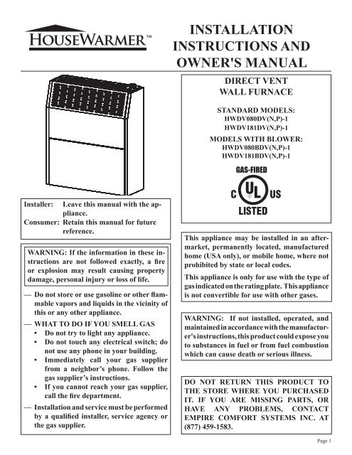
Installer: Leave this manual with the appliance.<br />
Consumer: Retain this manual for future<br />
reference.<br />
WARNING: If the information in these instructions<br />
are not followed exactly, a fire<br />
or explosion may result causing property<br />
damage, personal injury or loss of life.<br />
— Do not store or use gasoline or other flammable<br />
vapors and liquids in the vicinity of<br />
this or any other appliance.<br />
— WHAT TO DO IF YOU SMELL GAS<br />
• Do not try to light any appliance.<br />
• Do not touch any electrical switch; do<br />
not use any phone in your building.<br />
• Immediately call your gas supplier<br />
from a neighbor’s phone. Follow the<br />
gas supplier’s instructions.<br />
• If you cannot reach your gas supplier,<br />
call the fire department.<br />
— Installation and service must be performed<br />
by a qualified installer, service agency or<br />
the gas supplier.<br />
INSTALLATION<br />
INSTRUCTIONS AND<br />
OWNER'S MANUAL<br />
DIRECT VENT<br />
WALL FURNACE<br />
STANDARD MODELS:<br />
<strong>HWDV</strong>080DV(N,P)-1<br />
<strong>HWDV</strong>181DV(N,P)-1<br />
MODELS WITH BLOWER:<br />
<strong>HWDV</strong>080BDV(N,P)-1<br />
<strong>HWDV</strong>181BDV(N,P)-1<br />
GAS-FIRED<br />
This appliance may be installed in an aftermarket,<br />
permanently located, manufactured<br />
home (USA only), or mobile home, where not<br />
prohibited by state or local codes.<br />
This appliance is only for use with the type of<br />
gas indicated on the rating plate. This appliance<br />
is not convertible for use with other gases.<br />
WARNING: If not installed, operated, and<br />
maintained in accordance with the manufacturer's<br />
instructions, this product could expose you<br />
to substances in fuel or from fuel combustion<br />
which can cause death or serious illness.<br />
DO NOT RETURN THIS PRODUCT TO<br />
THE STORE WHERE YOU PURCHASED<br />
IT. IF YOU ARE MISSING PARTS, OR<br />
HAVE ANY PROBLEMS, CONTACT<br />
EMPIRE COMFORT SYSTEMS INC. AT<br />
(877) 459-1583.<br />
Page 1
Page 2<br />
TABLE OF CONTENTS<br />
SECTION PAGE<br />
Included in the Box .................................................................................................. 3<br />
Hardware Packets .................................................................................................... 4<br />
<strong>Tool</strong>s Needed ............................................................................................................. 4<br />
Gas Specifications .................................................................................................... 5<br />
Specifications ............................................................................................................ 5<br />
High Altitude Specifications .................................................................................... 5<br />
Unit Dimensions ....................................................................................................... 6<br />
Important Safety Information ................................................................................ 7<br />
Safety Information for Users of LP-Gas ................................................................ 8<br />
Introduction .............................................................................................................. 9<br />
Requirements for Massachusetts .......................................................................... 10<br />
Termination Clearances ......................................................................................... 11<br />
Gas Supply ......................................................................................................... 12-13<br />
Clearances ............................................................................................................... 13<br />
Installation Instructions Overview ....................................................................... 14<br />
Installation and Assembly ................................................................................ 15-16<br />
Interior Preparation and Installation of the Back of the Unit ...................... 17-19<br />
Interior Installation of the Front of the Unit ....................................................... 20<br />
Cutting the Vent Tubes ..................................................................................... 21-22<br />
Exterior Installation of the Venting ................................................................. 23-25<br />
Reassembly and Resealing Vent-Air Intake System ...................................... 26-28<br />
Installation of Optional Blower Kit HW125SCB ........................................... 29-32<br />
Before Operating Appliance ............................................................................. 33-36<br />
Operating Instructions .......................................................................................... 37<br />
Lighting Instructions ............................................................................................. 38<br />
To Turn Off Gas to Appliance ............................................................................... 38<br />
Pilot Flame Characteristics ................................................................................... 39<br />
Main Burner Flame Characteristics .................................................................... 39<br />
Maintenance Instructions ...................................................................................... 40<br />
Troubleshooting ...................................................................................................... 41<br />
How To Order Repair Parts .................................................................................. 41<br />
Parts List ............................................................................................................ 42-43<br />
Parts View ............................................................................................................... 44<br />
Service Notes ...................................................................................................... 45-47<br />
<strong>24632</strong>-0-<strong>0508</strong>
DIRECT VENT HEATER<br />
(INSIDE WALL MOUNTING PLATE<br />
ATTACHED ON BACK)<br />
HEATER<br />
HARDWARE PACKET<br />
VENT SHIELD<br />
INCLUDED IN THE BOX<br />
VENT KIT<br />
HARDWARE PACKET<br />
OUTSIDE WALL MOUNTING PLATE<br />
& VENT CAP<br />
INSTALLATION TEMPLATE<br />
(TEMPLATE FOR <strong>HWDV</strong>080<br />
ON REVERSE SIDE)<br />
INLET & OUTLET TUBES<br />
<strong>24632</strong>-0-<strong>0508</strong> Page 3
Page 4<br />
HEATER<br />
HARDWARE PACKET<br />
NYLON WASHER (2)<br />
PLASTIC TOGGLE (6)<br />
#10 X 1 ½”<br />
SLOTTED HEX HEAD SCREW (6)<br />
PHILLIPS SCREW DRIVER<br />
SNIPS<br />
DRILL<br />
HARDWARE PACKETS<br />
TOOLS NEEDED<br />
5/16 NUT DRIVER<br />
CAULKING<br />
SAW<br />
VENT KIT<br />
HARDWARE PACKET<br />
#10 X ½” PHILLIPS HEX HEAD SCREW (3)<br />
#10 X 2 ½” HEX HEAD SCREW (4)<br />
ADJUSTABLE WRENCH<br />
TAPE MEASURE<br />
<strong>24632</strong>-0-<strong>0508</strong>
GAS SPECIFICATIONS<br />
MODEL FUEL MAXIMUM INPUT MINIMUM INPUT<br />
HW080<br />
8,000 Btu/hr 5,000 Btu/hr<br />
HW181<br />
Propane/LP -- Natural gas<br />
18,000 Btu/hr<br />
9,000 Btu/hr NAT<br />
9,500 Btu/hr LP<br />
MANIFOLD PRESSURE<br />
Gas Inlet 3/8"<br />
Natural gas: 4" water column pressure<br />
Propane/LP gas: 10.0" water column pressure<br />
SUPPLY MINIMUM PRESSURE MAXIMUM PRESSURE<br />
Natural Gas 5" W.C.P. 10.5" W.C.P.<br />
LP Gas 11" W.C.P. 13" W.C.P.<br />
Note: Appliance input ratings are based on sea level operation and need not be changed for operation up to 2,000 feet.<br />
SPECIFICATIONS<br />
MODELS <strong>HWDV</strong>080(B)DV <strong>HWDV</strong>181(B)DV<br />
COMBUSTION ATMOSPHERIC BURNER<br />
STANDARD HEATING SPACE 85 - 250 Sq. Ft. 169 - 529 Sq. Ft.<br />
EXTERNAL DIMENSIONS INCHES<br />
HEIGHT 21 11/16" 25 3/16"<br />
WIDTH 18 5/16" 22 5/16"<br />
DEPTH 8 7/8" 9 3/8"<br />
NET WEIGHT LBS. 33.5 45.5<br />
MAX. GAS CONSUMPTION 8,000 Btu/hr. 18,000 Btu/hr.<br />
SAFETY DEVICES Safety valve (thermocouple)<br />
Warning: This direct vent wall furnace is equipped for Natural or Propane gas. Field conversion is not permitted.<br />
HIGH ALTITUDE SPECIFICATIONS<br />
For altitudes/elevations above 2,000 feet (610 m), input ratings should be reduced at the rate of 4% for each 1,000 feet (305 m) above<br />
sea level. Canadian High Altitudes for locations having an elevation above mean sea level between 2,000 feet (609.9 m) and 4,500 feet<br />
(1,370 m), use orifices as indicated in the following table:<br />
Model<br />
0 - 2,000 feet (0 - 610 m) 2,000 - 4,500 feet (610 - 1 370 m)<br />
Main Burner Orifice/Gas Pressure Main Burner Orifice/Gas Pressure<br />
Natural Gas LP Gas Natural Gas LP Gas<br />
HW080 #55 (4") #66 (10") #1.27 mm (4") #67 (10")<br />
HW181 #49 (4") #56 (10") #50 (4") #57 (10")<br />
<strong>24632</strong>-0-<strong>0508</strong> Page 5
Page 6<br />
UNIT DIMENSIONS<br />
MAKE SURE THAT APPLIANCE IS SUITABLE FOR THE GAS SUPPLY AVAILABLE:<br />
NATURAL GAS OR PROPANE/LP.<br />
<strong>24632</strong>-0-<strong>0508</strong>
IMPORTANT SAFETY INFORMATION<br />
Children and adults should be alerted to the hazards<br />
of high surface temperatures and should stay<br />
away to avoid burns or clothing ignition.<br />
Any safety screen or guard removed for servicing<br />
must be replaced prior to operating the heater.<br />
Do not use this heater if it has been under water.<br />
Immediately call a qualified service technician to<br />
inspect the heater and to replace any part of the<br />
control system and any gas control which has been<br />
under water.<br />
Young children should be carefully supervised when<br />
they are in the same room as the heater.<br />
Installation and repair should be done by a qualified<br />
service person. Heater should be inspected before<br />
use and at least annually by a qualified service<br />
person.<br />
More frequent cleaning may be required due to excessive<br />
lint from carpeting, bedding material etc. It<br />
is imperative that control compartments, burners,<br />
and circulating air passageways of the appliance be<br />
kept clean.<br />
Follow State and Local codes for installation.<br />
DO NOT put anything around or on top of the furnace<br />
that will obstruct the flow of combustion and<br />
ventilation air.<br />
DO keep the appliance area clear and free from<br />
combustible material, gasoline and other flammable<br />
vapors and liquids.<br />
DO examine venting system periodically and replace<br />
damaged parts.<br />
DO make a periodic visual check of pilot and burners.<br />
Clean and replace damaged parts.<br />
CAUTION: Pilot hole cover must be kept tightly<br />
closed during operation.<br />
Vent cap hot while furnace is in operation.<br />
<strong>24632</strong>-0-<strong>0508</strong> Page 7
Propane (LP-Gas) is a flammable gas which can cause fires<br />
and explosions. In its natural state, propane is odorless and<br />
colorless. You may not know all the following safety precautions<br />
which can protect both you and your family from an accident.<br />
Read them carefully now, then review them point by point<br />
• Do not operate electric switches, light matches, use your<br />
phone. Do not do anything that could ignite the gas.<br />
• Get everyone out of the building, vehicle, trailer, or area. Do<br />
that IMMEDIATELY.<br />
• Close all gas tank or cylinder supply valves.<br />
• LP-Gas is heavier than air and may settle in low areas such<br />
as basements. When you have reason to suspect a gas leak,<br />
keep out of basements and other low areas. Stay out until<br />
firefighters declare them to be safe.<br />
NO ODOR DETECTED - ODOR FADE<br />
Some people cannot smell well. Some people cannot smell the there is rust inside the storage tank or in iron gas pipes.<br />
odor of the chemical put into the gas. You must find out if you<br />
The odorant in escaped gas can adsorb or absorb onto or into walls,<br />
can smell the odorant in propane. Smoking can decrease your<br />
masonry and other materials and fabrics in a room. That will take<br />
ability to smell. Being around an odor for a time can affect your<br />
some of the odorant out of the gas, reducing its odor intensity.<br />
sensitivity or ability to detect that odor. Sometimes other odors<br />
in the area mask the gas odor. People may not smell the gas odor LP-Gas may stratify in a closed area, and the odor intensity could<br />
or their minds are on something else. Thinking about smelling a vary at different levels. Since it is heavier than air, there may be<br />
gas odor can make it easier to smell.<br />
more odor at lower levels. Always be sensitive to the slightest gas<br />
odor. If you detect any odor, treat it as a serious leak. Immediately<br />
The odorant in LP-gas is colorless, and it can fade under some<br />
go into action as instructed earlier.<br />
circumstances. For example, if there is an underground leak, the<br />
movement of the gas through soil can filter the odorant. Odorants<br />
in LP-Gas also are subject to oxidation. This fading can occur if<br />
Page 8<br />
SAFETY INFORMATION FOR USERS OF LP-GAS<br />
SOME POINTS TO REMEMBER<br />
with the members of your household. Someday when there<br />
may not be a minute to lose, everyone's safety will depend on<br />
knowing exactly what to do. If, after reading the following<br />
information, you feel you still need more information, please<br />
contact your gas supplier.<br />
LP-GAS WARNING ODOR<br />
If a gas leak happens, you should be able to smell the gas because of the odorant put in the LP-Gas.<br />
That's your signal to go into immediate action!<br />
• Learn to recognize the odor of LP-gas. Your local LP-Gas<br />
Dealer can give you a "Scratch and Sniff" pamphlet. Use it<br />
to find out what the propane odor smells like. If you suspect<br />
that your LP-Gas has a weak or abnormal odor, call your<br />
LP-Gas Dealer.<br />
• If you are not qualified, do not light pilot lights, perform<br />
service, or make adjustments to appliances on the LP-Gas<br />
system. If you are qualified, consciously think about the odor<br />
of LP-Gas prior to and while lighting pilot lights or performing<br />
service or making adjustments.<br />
• Sometimes a basement or a closed-up house has a musty<br />
smell that can cover up the LP-Gas odor. Do not try to light<br />
pilot lights, perform service, or make adjustments in an area<br />
where the conditions are such that you may not detect the<br />
odor if there has been a leak of LP-Gas.<br />
• Odor fade, due to oxidation by rust or adsorption on walls<br />
of new cylinders and tanks, is possible. Therefore, people<br />
should be particularly alert and careful when new tanks or<br />
cylinders are placed in service. Odor fade can occur in new<br />
tanks, or reinstalled old tanks, if they are filled and allowed<br />
• Use your neighbor's phone and call a trained LP-Gas service<br />
person and the fire department. Even though you may not<br />
continue to smell gas, do not turn on the gas again. Do not<br />
re-enter the building, vehicle, trailer, or area.<br />
• Finally, let the service man and firefighters check for escaped<br />
gas. Have them air out the area before you return. Properly<br />
trained LP-Gas service people should repair the leak, then<br />
check and relight the gas appliance for you.<br />
to set too long before refilling. Cylinders and tanks which<br />
have been out of service for a time may develop internal rust<br />
which will cause odor fade. If such conditions are suspected<br />
to exist, a periodic sniff test of the gas is advisable. If you<br />
have any question about the gas odor, call your LP-gas dealer.<br />
A periodic sniff test of the LP-gas is a good safety measure<br />
under any condition.<br />
• If, at any time, you do not smell the LP-Gas odorant and you<br />
think you should, assume you have a leak. Then take the same<br />
immediate action recommended above for the occasion when<br />
you do detect the odorized LP-Gas.<br />
• If you experience a complete "gas out," (the container is under<br />
no vapor pressure), turn the tank valve off immediately.<br />
If the container valve is left on, the container may draw in<br />
some air through openings such as pilot light orifices. If this<br />
occurs, some new internal rusting could occur. If the valve is<br />
left open, then treat the container as a new tank. Always be<br />
sure your container is under vapor pressure by turning it off<br />
at the container before it goes completely empty or having it<br />
refilled before it is completely empty.<br />
<strong>24632</strong>-0-<strong>0508</strong>
Always consult your local Building Department regarding regulations,<br />
codes or ordinances which apply to the installation of a<br />
direct vent wall furnace.<br />
Instructions to Installer<br />
1. Installer must leave instruction manual with owner after installation.<br />
2. Installer must have owner fill out and mail warranty card supplied<br />
with furnace.<br />
3. Installer should show owner how to start and operate furnace<br />
and thermostat.<br />
Warning:<br />
Any change to this furnace or its control can be dangerous.<br />
This is a heating appliance and any panel, door or<br />
guard removed for servicing an appliance must be replaced<br />
prior to operating the appliance.<br />
General Information<br />
This furnace is design certified in accordance with American National<br />
Standard/CSA Standard Z21.86 and CSA 2.32 by Underwriters<br />
Laboratory as a direct vent wall furnace to be installed<br />
according to these instructions.<br />
Any alteration of the original design, installed other than as<br />
shown in these instructions or use with a type of gas not shown<br />
on the rating plate is the responsibility of the person and company<br />
making the change.<br />
Notice: During initial firing of this unit, its paint will bake out and<br />
smoke will occur. To prevent triggering of smoke alarms, ventilate<br />
the room in which the unit is installed.<br />
Installation in Residential Garages<br />
Gas utilization equipment in residential garages shall be installed<br />
so that all burners and burner ignition devices are located not<br />
less than 18" above the floor. Such equipment shall be located,<br />
or protected, so it is not subject to physical damage by a moving<br />
vehicle.<br />
INTRODUCTION<br />
Qualified Installing Agency<br />
Installation and replacement of gas piping, gas utilization equipment<br />
or accessories and repair and servicing of equipment shall<br />
be performed by a qualified agency. The term “qualified agency”<br />
means any individual, firm, corporation or company which either<br />
in person or through a representative is engaged in and is responsible<br />
for (1) the installation or replacement of gas piping or (2) the<br />
connection, installation, repair or servicing of equipment, who is<br />
experienced in such work, familiar with all precautions required<br />
and has complied with all the requirements of the authority having<br />
jurisdiction.<br />
State of Massachusetts: The installation must be made by a<br />
licensed plumber or gas fitter in the Commonwealth of Massachusetts.<br />
The state of Massachusetts requires that a flexible<br />
appliance connector cannot exceed three feet in length.<br />
The installation must conform with local codes or, in the absence<br />
of local codes, with the National Fuel Gas Code ANSI Z223.1/<br />
NFPA 54* Natural Gas and Propane Installation Code, CSA<br />
B149.1.<br />
*Available from the American National Standards Institute, Inc., 11 West 42nd St.,<br />
New York, N.Y. 10036.<br />
The vent terminal of a direct vent appliance, with an input of<br />
10,000 Btu per hour (3 kW) or less shall be located at least 6"<br />
(150 mm) from any air opening into a building, and such an appliance<br />
with an input over 10,000 Btu per hour (3 kW) but not<br />
over 50,000 Btu per hour (14.7 kW) shall be installed with a 9"<br />
(229 mm) vent terminal clearance and the bottom of the vent terminal<br />
and the air intake shall be located at least 12" (305 mm)<br />
above grade.<br />
WARNING: The nearest point of the vent cap should be a<br />
minimum horizontal distance of six (6) feet (1.8 m) from<br />
any pressure regulator. In case of regulator malfunction,<br />
the six (6) feet (1.8 m) distance will reduce the chance of<br />
gas entering the vent cap.<br />
<strong>24632</strong>-0-<strong>0508</strong> Page 9
Page 10<br />
REQUIREMENTS FOR MASSACHUSETTS<br />
For all side wall horizontally vented gas fueled equipment installed<br />
in every dwelling, building or structure used in whole or in part<br />
for residential purposes, including those owned or operated by the<br />
Commonwealth and where the side wall exhaust vent termination<br />
is less than seven (7) feet above finished grade in the area of the<br />
venting, including but not limited to decks and porches, the following<br />
requirements shall be satisfied:<br />
1. INSTALLATION OF CARBON MONOXIDE DETECTORS.<br />
At the time of installation of the side wall horizontal vented<br />
gas fueled equipment, the installing plumber or gasfitter shall<br />
observe that a hard wired carbon monoxide detector with an<br />
alarm and battery back-up is installed on the floor level where<br />
the gas equipment is to be installed. In addition, the installing<br />
plumber or gasfitter shall observe that a battery operated or<br />
hard wired carbon monoxide detector with an alarm is installed<br />
on each additional level of the dwelling, building or structure<br />
served by the side wall horizontal vented gas fueled equipment.<br />
It shall be the responsibility of the property owner to secure the<br />
services of qualified licensed professionals for the installation<br />
of hard wired carbon monoxide detectors.<br />
(a) In the event that the side wall horizontally vented gas<br />
fueled equipment is installed in a crawl space or an attic,<br />
the hard wired carbon monoxide detector with alarm and<br />
battery back-up may be installed on the next adjacent floor<br />
level.<br />
(b) In the event that the requirements of this subdivision can<br />
not be met at the time of completion of installation, the<br />
owner shall have a period of thirty (30) days to comply<br />
with the above requirements; provided, however, that during<br />
said thirty (30) day period, a battery operated carbon<br />
monoxide detector with an alarm shall be installed.<br />
2. APPROVED CARBON MONOXIDE DETECTORS. Each<br />
carbon monoxide detector as required in accordance with the<br />
above provisions shall comply with NFPA 720 and be ANSI/UL<br />
2034 listed and IAS certified.<br />
3. SIGNAGE. A metal or plastic identification plate shall be permanently<br />
mounted to the exterior of the building at a minimum<br />
height of eight (8) feet above grade directly in line with the<br />
exhaust vent terminal for the horizontally vented gas fueled<br />
heating appliance or equipment. The sign shall read, in print<br />
size no less than one-half (1/2) inch in size, “GAS VENT<br />
DIRECTLY BELOW. KEEP CLEAR OF ALL OBSTRUC-<br />
TIONS”.<br />
4. INSPECTION. The state or local gas inspector of the side wall<br />
horizontally vented gas fueled equipment shall not approve<br />
the installation unless, upon inspection, the inspector observes<br />
carbon monoxide detectors and signage installed in accordance<br />
with the provisions of 248 CMR 5.08(2)(a) 1 through 4.<br />
(b) EXEMPTIONS: The following equipment is exempt from<br />
248 CMR 5.08(2)(a)1 through 4:<br />
1. The equipment listed in Chapter 10 entitled “<strong>Equipment</strong><br />
Not Required To Be Vented” in the most current<br />
edition of NFPA 54 as adopted by the Board; and<br />
2. Product Approved side wall horizontally vented gas<br />
fueled equipment installed in a room or structure<br />
separate from the dwelling, building or structure used<br />
in whole or in part for residential purposes.<br />
(c) MANUFACTURER REQUIREMENTS - GAS EQUIP-<br />
MENT VENTING SYSTEM PROVIDED. When the<br />
manufacturer of Product Approved side wall horizontally<br />
vented gas equipment provides a venting system design<br />
or venting system components with the equipment, the<br />
instructions provided by the manufacturer for installation<br />
of the equipment and the venting system shall include:<br />
1. Detailed instructions for the installation of the venting<br />
system design or the venting system components;<br />
and<br />
2. A complete parts list for the venting system design<br />
or venting system.<br />
(e) A copy of all installation instructions for all Product Approved<br />
side wall horizontally vented gas fueled equipment,<br />
all venting instructions, all parts lists for venting instructions,<br />
and/or all venting design instructions shall remain<br />
with the appliance or equipment at the completion of the<br />
installation.<br />
<strong>24632</strong>-0-<strong>0508</strong>
TERMINATION CLEARANCES<br />
Description US Installations 1<br />
A Clearance above grade, veranda, porch, deck, or balcony 12 inches (305 mm)<br />
B Clearance to window or door that may be open 6 inches (152 mm) for appliance ≤ 10,000 Btuh (3 kW), 9 inches<br />
(229 mm) for appliances > 10,000 Btuh (3 kW) and ≤ 50,000 Btuh<br />
(15 kW), 12 inches (305 mm) for appliances > 50,000 Btuh (15 kW)<br />
C Clearance to permanently closed window *<br />
D Vertical clearance to ventilated soffit located above the<br />
terminal within a horizontal distance of 2 feet (610 mm)<br />
from the center line of the terminal<br />
*<br />
E Clearance to unventilated soffit *<br />
F Clearance to outside corner 24"<br />
G Clearance to inside corner 24"<br />
H Clearance to each side of center line extended above meter/regulator<br />
assembly<br />
*<br />
I Clearance to service regulator vent outlet *<br />
J Clearance to non-mechanical air supply inlet to building<br />
or the combustion air inlet to any other appliance.<br />
6 inches (152 mm) for appliance ≤ 10,000 Btuh (3 kW), 9 inches<br />
(229 mm) for appliances > 10,000 Btuh (3 kW) and ≤ 50,000 Btuh<br />
(15 kW), 12 inches (305 mm) for appliances > 50,000 Btuh (15 kW)<br />
K Clearance to a mechanical air supply inlet 3 feet (914 mm) above if within 10 feet (3.04 m) horizontally<br />
L Clearance above paved sidewalk or paved driveway located<br />
on public property<br />
*<br />
M Clearance under veranda, porch, deck, or balcony. *<br />
The minimum distance from the center of the outside vent to the nearest inside and outside corner or obstruction or overhang is 24"<br />
(457 mm).<br />
1 In accordance with current ANSI Z223.1/NFPA 54, National Fuel Gas Code<br />
* For clearances not specified in ANSI Z223.1/NFPA 54 or CSA B149.1, one of the following shall be indicated:<br />
a) A minimum clearance value determined by testing in accordance with section 2.19.6, or;<br />
b) A reference to the following footnote:<br />
“Clearance in accordance with local installation codes and the requirements of the gas supplier.”<br />
<strong>24632</strong>-0-<strong>0508</strong> Page 11
Locating Gas Supply<br />
The gas line can enter the unit either through the floor or outside<br />
wall. The gas line opening should be made at this time. Location<br />
of the opening will be determined by the position of floor joists<br />
and the valve and union used for servicing.<br />
Recommended Gas Pipe Diameter<br />
Pipe Length Schedule 40 Pipe<br />
Inside Diameter<br />
0-10 feet<br />
0-3 meters<br />
10-40 feet<br />
4-12 meters<br />
40-100 feet<br />
13-30 meters<br />
100-150 feet<br />
31-46 meters<br />
Note: Never use plastic pipe. Check to confirm whether your local<br />
codes allow copper tubing or galvanized.<br />
Note: Since some municipalities have additional local codes, it is<br />
always best to consult your local authority and installation code.<br />
The use of the following gas connectors is recommended:<br />
— ANS Z21.24 Appliance Connectors of Corrugated Metal Tubing<br />
and Fittings<br />
— ANS Z21.45 Assembled Flexible Appliance Connectors of<br />
Other Than All-Metal Construction<br />
The above connectors may be used if acceptable by the authority<br />
having jurisdiction. The state of Massachusetts requires that a<br />
flexible appliance connector cannot exceed three feet in length.<br />
Page 12<br />
Figure 1<br />
Tubing, Type L<br />
Outside Diameter<br />
Nat. L.P. Nat. L.P.<br />
1/2”<br />
12.7 mm<br />
1/2”<br />
12.7 mm<br />
1/2”<br />
12.7 mm<br />
3/4”<br />
19 mm<br />
3/8”<br />
9.5 mm<br />
1/2”<br />
12.7 mm<br />
1/2”<br />
12.7 mm<br />
1/2”<br />
12.7 mm<br />
1/2”<br />
12.7 mm<br />
5/8”<br />
15.9 mm<br />
3/4”<br />
19 mm<br />
7/8”<br />
22.2 mm<br />
Consult the current National Fuel Gas Code, ANSI Z223.1 CAN/<br />
CGA-B149 (.1 or .2) installation code.<br />
GAS SUPPLY<br />
3/8”<br />
9.5 mm<br />
1/2”<br />
12.7 mm<br />
1/2”<br />
12.7 mm<br />
3/4”<br />
19 mm<br />
Installing a New Main Gas Cock<br />
Each appliance should have its own manual gas cock.<br />
A manual main gas cock should be located in the vicinity of<br />
the unit. Where none exists, or where its size or location is not<br />
adequate, contact your local authorized installer for installation<br />
or relocation.<br />
Compounds used on threaded joints of gas piping shall be resistant<br />
to the action of liquefied petroleum gases. The gas lines must be<br />
checked for leaks by the installer. This should be done with a soap<br />
solution watching for bubbles on all exposed connections, and if<br />
unexposed, a pressure test should be made.<br />
Never use an exposed flame to check for leaks. Appliance must be<br />
disconnected from piping at inlet of control valve and pipe capped<br />
or plugged for pressure test. Never pressure test with appliance<br />
connected; control valve will sustain damage!<br />
A gas valve and ground joint union should be installed in the gas<br />
line upstream of the gas control to aid in servicing. It is required<br />
by the National Fuel Gas Code that a drip line be installed near<br />
the gas inlet. This should consist of a vertical length of pipe tee<br />
connected into the gas line that is capped on the bottom in which<br />
condensation and foreign particles may collect.<br />
FLEXIBLE GAS LINE CONNECTION<br />
GAS SUPPLY<br />
TEE HANDLE<br />
NPT NIPPLE REGULATOR<br />
FLEX TUBE<br />
FLARE SHUT OFF VALVE<br />
CLOSE NIPPLE<br />
TEE HANDLE<br />
NPT GAS SUPPLY<br />
FLARE FITTING<br />
RIGID GAS LINE CONNECTION<br />
SHUT OFF VALVE<br />
3/8 NIPPLE<br />
Method of Installing a Tee Fitting Sediment Trap<br />
Figure 2<br />
NPT UNION<br />
VALVE<br />
REGULATOR<br />
VALVE<br />
<strong>24632</strong>-0-<strong>0508</strong>
Pressure Testing of the Gas Supply System<br />
1. To check the inlet pressure to the gas valve, a 1/8" (3 mm) N.P.T.<br />
plugged tapping, accessible for test gauge connection, must be<br />
placed immediately upstream of the gas supply connection to<br />
the appliance.<br />
2. The appliance and its individual shutoff valve must be<br />
disconnected from the gas supply piping system during any<br />
pressure testing of that system at test pressures in excess of<br />
1/2 psig (3.5 kPa).<br />
3. The appliance must be isolated from the gas supply piping<br />
system by closing its individual manual shutoff valve during<br />
any pressure testing of the gas supply piping system at test<br />
pressures equal to or less than 1/2 psig (3.5 kPa).<br />
Attention! If one of the above procedures results in pressures in<br />
excess of 1/2 psig (14" w.c.) (3.5 kPa) on the appliance gas valve,<br />
it will result in a hazardous condition.<br />
1. In selecting a location for installation, it is necessary to provide<br />
adequate accessibility clearances for servicing and proper<br />
installation.<br />
2. Unit is supported by a wall bracket secured to the wall.<br />
3. The minimum clearances from casing to combustible construction<br />
is 36" (914.4 mm) on top, 6" (152 mm) on each side and<br />
4" (102 mm) from the floor or from the top surface of carpeting,<br />
tile or other floor covering and 0" (0 mm) to rear wall.<br />
4. The minimum distance from the center of the vent cap to the<br />
nearest outside corner or obstruction is 24" (610 mm).<br />
5. The minimum wall depth is 4 1/2" (114.3 mm) and the<br />
maximum is 12" (304.8 mm). The use of tubes not supplied<br />
by the manufacturer results in unsatisfactory performance.<br />
The vent terminal of a direct vent appliance, with an input of<br />
50,000 (14.6 KW) BTU per hour or less shall be located at least 9"<br />
(229 mm) from any opening through which flue gases could enter<br />
a building. The bottom of the vent terminal and the air intake shall<br />
be located at least 12" (305 mm) above grade.<br />
The vent terminal of a direct vent appliance, with an input of<br />
10,000 Btu per hour (3 kW) or less shall be located at least 6"<br />
(150 mm) from any air opening into a building, and such an appliance<br />
with an input over 10,000 Btu per hour (3 kW) but not<br />
over 50,000 Btu per hour (14.7 kW) shall be installed with a 9"<br />
(229 mm) vent terminal clearance and the bottom of the vent terminal<br />
and the air intake shall be located at least 12" (305 mm)<br />
above grade.<br />
GAS SUPPLY (continued)<br />
CLEARANCES<br />
Checking Manifold Pressure<br />
Both Propane and Natural have a pressure regulator attached to<br />
the gas valve. Natural gas models will have a manifold pressure<br />
of approximately 4.0" w.c. (.996 kPa) at the valve outlet with<br />
the inlet pressure to the valve from a minimum of 5.0" w.c.<br />
(1.245 kPa) for the purpose of input adjustment to a maximum of<br />
10.5" w.c. (2.61 kPa). Propane gas models will have a manifold<br />
pressure approximately 10.0" w.c. (2.49 kPa) at the valve<br />
outlet with the inlet pressure to the valve from a minimum of<br />
11.0" w.c. (2.739 kPa) for the purpose of input adjustment to a<br />
maximum of 13.0" w.c. (3.237 kPa).<br />
A 1/8" (3 mm) N.P.T. plugged tapping, accessible for test gauge<br />
connection, is located on the side of the gas pressure regulator.<br />
WARNING: The nearest point of the vent cap should be a<br />
minimum horizontal distance of six (6) (1.83m) feet from<br />
any pressure regulator. In case of regulator malfunction, the<br />
six (6) foot (1.83m) distance will reduce the chance of gas<br />
entering the vent cap.<br />
<strong>24632</strong>-0-<strong>0508</strong> Page 13
Location - All Models<br />
Page 14<br />
INSTALLATION INSTRUCTIONS OVERVIEW<br />
Select a location near the center of the space to be heated. Overflow<br />
heat will circulate through doorways into adjacent rooms.<br />
The furnace is to be located on an outside wall. Locate wall studs<br />
so that wall opening will be located between wall studs. One wall<br />
stud can be used for attachment of inside wall plate. The wall<br />
opening required as shown in Figure 3 is a minimum diameter of<br />
6 1/4" (159 mm). The inside wall plate and the outside wall plate are<br />
large enough to permit a wall opening diameter of 8" (203 mm).<br />
A template is provided in furnace carton for positioning furnace<br />
on the wall. Also, refer to Figure 3 for positioning the furnace on<br />
wall and for locating gas line connection.<br />
Figure 3<br />
For large homes or spread-out floor plans, two or more furnaces<br />
are recommended.<br />
Do not locate furnace where a door could swing over the outer<br />
casing, or where circulation could be retarded by furniture or<br />
cabinets. See Figure 4.<br />
Do not install in a closet, alcove or small hallway where the furnace<br />
could be isolated by closing doors to the heated space. See Figures<br />
5 and 6.<br />
When location is selected, check the walls to make sure there are<br />
no obstructions such as pipes, electric wiring, etc., which would<br />
interfere with the installation of the furnace or vent pipe.<br />
See Page 18, Box 4 for dimensions.<br />
Figure 4 Figure 5 Figure 6<br />
<strong>24632</strong>-0-<strong>0508</strong>
Note: All references must be considered as if the observer is standing in front of the wall and/or appliance.<br />
1<br />
WALL<br />
MOUNTING<br />
SCREWS<br />
INSTALLATION AND ASSEMBLY<br />
WARNING: Any change to this heater or its control can be dangerous. Provide adequate clearances and<br />
accessibility for purposes of servicing and proper operation.<br />
A manufactured home (USA only) installation must conform with the Manufactured Home Construction and Safety Standard, Title 24<br />
CFR, Part 3280 or, when such standard is not applicable, the Standard for Manufactured Home Installations, ANSI Z225.1.<br />
Due to high surface temperature, keep children, clothing, and furniture away. Keep burner and control compartments clean.<br />
INSTALLATION OVERVIEW<br />
WARNING: Improper installation, adjustments, alteration, service, or maintenance can cause property damage, personal injury<br />
or loss of life.<br />
Installation and service must be performed by a qualified installer, service agency, or the gas supplier.<br />
These wall furnace models are designed for direct venting through a wall. Only venting components approved for these furnaces may<br />
be used.<br />
This unit is to be installed on a wall from 4 1/2" to 12" (114.3 mm to 304.8 mm) thick.<br />
WALL MOUNTING<br />
PLATE<br />
HEATER TO<br />
BACK CASING<br />
MOUNTING<br />
SCREWS<br />
WALL<br />
MOUNTING TAB<br />
Mark the venting system hole location (as indicated on page<br />
18) and the six holes through the wall mounting plate. Drill<br />
accordingly. Insert the four wall anchors provided and tighten<br />
the wall mounting plate firmly. Use special anchor fasteners if<br />
the heater is to be installed on a wooden (hollow) wall. Line<br />
up the two (2) tabs on the top of the wall mounting plate with<br />
the holes in the back of the unit. Slide the back of the unit onto<br />
the tabs of the wall mounting plate. Secure the back of the unit<br />
into place using two (2) screws. Replace casing door. The heater<br />
is now ready to receive the venting system assembly from the<br />
opposite side of the wall.<br />
Note: All references must be considered as if the observer is<br />
standing in front of the wall and/or appliance.<br />
IMPORTANT: The venting system must be properly<br />
installed to insure proper and safe operation. The venting<br />
system must also be properly re-installed and re-sealed to<br />
insure proper and safe operation.<br />
<strong>24632</strong>-0-<strong>0508</strong> Page 15
2<br />
3<br />
Page 16<br />
INSTALLATION AND ASSEMBLY<br />
SILICON-BASED<br />
SEALANT<br />
MOUNTING<br />
PLATE<br />
CAP<br />
FLUE OUTLET<br />
TUBE<br />
AIR INLET<br />
TUBE<br />
INSTALLATION OF HOUSEWARMER PRODUCT<br />
Failure to position these parts in accordance with diagram<br />
or failure to use only parts specifically approved with these<br />
appliances may result in property damage or personal<br />
injury.<br />
INSTALLATION AND ANY REPAIRS TO THIS APPLIANCE MUST BE DONE BY A QUALIFIED<br />
SERVICE PERSON.<br />
WARNING: Read the installation instructions thoroughly before cutting or drilling any holes for<br />
installation.<br />
WARNING: Do not remove any rating plates attached to the unit.<br />
A qualified service person should be called to inspect this appliance annually.<br />
Have all of your appliances checked annually.<br />
CLEARANCES TO COMBUSTIBLES<br />
Allow clearances (for all models) to adjacent combustible construction.<br />
IMPORTANT: A qualified service person must install this appliance.<br />
Installation must conform to local codes, or in the absence<br />
of local codes, with the latest edition of the National Fuel<br />
Gas Code, ANSI Z223.1.<br />
<strong>24632</strong>-0-<strong>0508</strong>
2<br />
INTERIOR PREPARATION AND INSTALLATION OF THE BACK OF THE UNIT<br />
1 Before installing unit, remove wall mounting plate from back of unit.<br />
3<br />
MOUNTING TEMPLATE FOR<br />
SEE OTHER SIDE FOR <strong>HWDV</strong>080<br />
Locate the wall mounting plate template included in your kit<br />
and remove the perforated sections. Use painters tape to secure<br />
the wall mounting plate template onto the interior wall where<br />
the heater will be located. (Template for <strong>HWDV</strong>080 will be on<br />
the opposite side of the shown template.)<br />
Trace the template wall hole and (if applicable) the gas inlet hole onto the wall. Mark the six (6) wall mounting plate screw<br />
holes onto the wall. The size of the gas inlet hole will depend upon the size of gas pipe coming into the unit. (See page 17,<br />
box 2 and page 18, box 4).<br />
<strong>24632</strong>-0-<strong>0508</strong> Page 17
INTERIOR PREPARATION AND INSTALLATION OF THE BACK OF THE UNIT<br />
4<br />
5<br />
MARKING FOR<br />
WALL MOUNTING<br />
PLATE HOLES<br />
Page 18<br />
Housewarmer recommends the use of the wall template to properly cut the wall holes and place the heater. If the template is<br />
damaged or not included, refer to the table and graphic below for proper alignment of the wall holes and heater.. Be sure the<br />
baseboard does not get in the way.<br />
FLOOR LINE<br />
MARKING FOR<br />
GAS INLET HOLE<br />
MARKING FOR<br />
WALL HOLE<br />
MEASUREMENTS<br />
Model <strong>HWDV</strong>080(B)DV <strong>HWDV</strong>181(B)DV<br />
C 7 3/8" 11 3/8"<br />
D 10 7/8" 10 7/8"<br />
E 21" 24 1/2"<br />
F 9 1/4" 9 1/4"<br />
G 4" 4"<br />
I 6 1/4" 6 1/4"<br />
Remove the template from the wall after the holes are marked.<br />
The hole location markings will be present on the wall.<br />
<strong>24632</strong>-0-<strong>0508</strong>
INTERIOR PREPARATION AND INSTALLATION OF THE BACK OF THE UNIT<br />
6<br />
7<br />
8<br />
9<br />
Pilot<br />
Hole<br />
Drill a pilot hole inside of the traced circle so that a jigsaw can<br />
be used to cut the holes out.<br />
Use a jigsaw to cut the holes out of the wall and discard the<br />
inner circle debris. The wall is now prepared for the installation<br />
of the unit.<br />
Pivot and remove casing door. Remove two screws from the<br />
back inside of the unit and detach the wall mounting plate from<br />
outside back of the unit.<br />
Locate the studs in the wall and use at least four (4) wood screws<br />
to attach the wall mounting plate to the wall.<br />
If installing onto drywall (not into a stud), anchors must be<br />
used.<br />
<strong>24632</strong>-0-<strong>0508</strong> Page 19
1<br />
2<br />
3<br />
Page 20<br />
INTERIOR INSTALLATION OF THE FRONT OF THE UNIT<br />
GAS LINE<br />
Line up the two (2) tabs on the top of the wall mounting plate<br />
with the holes in the back of the unit. Slide the back of the unit<br />
onto the tabs of the wall mounting plate.<br />
Secure the back of the unit into place using two (2) screws.<br />
Replace casing door.<br />
After the back of the unit is attached to the wall, bring in the<br />
gas line as shown on page 18, or follow the installation template<br />
indications. Following your city, local and state codes, attach the<br />
gas line to the unit.<br />
NOTE: The gas line runs through the wall or floor of the<br />
house..<br />
<strong>24632</strong>-0-<strong>0508</strong>
CUTTING THE VENT TUBES<br />
NOTE: Flue outlet tube and air inlet tube should be measured and cut to the proper length from the back of the unit to the outside wall<br />
of the house. See page 22, boxes 3 and 4.<br />
IMPORTANT: The appliance’s venting system should be inspected at least once a year and immediately cleaned if necessary.<br />
1<br />
2<br />
4 1/2” to 12”<br />
THICK WALL<br />
MOUNTING PLATE<br />
CAP<br />
AIR INLET TUBE<br />
FLUE OUTLET TUBE<br />
SCREWS (3X)<br />
LONG SCREWS (4X)<br />
This unit is to be installed on wall from 4 1/2" to 12" (114.3 mm to 304.8 mm) thick.<br />
<strong>24632</strong>-0-<strong>0508</strong> Page 21
Page 22<br />
CUTTING THE VENT TUBES<br />
With the furnace installed on wall the 5" (127 mm) diameter air inlet tube and 3" (76 mm) diameter flue outlet tube are to be marked<br />
and cut using the following procedure. After cutting the tubes, each tube should be individually checked for proper length before<br />
installing by fitting in place.<br />
3<br />
4<br />
5<br />
MARKER<br />
FLUE OUTLET TUBE<br />
COLLAR OF<br />
FLUE OUTLET<br />
Attach 5" (127 mm) diameter air inlet tube onto the collar of air drop<br />
assembly. Be sure 5" (127 mm) diameter air inlet tube is placed as<br />
far as possible onto the collar of the air drop assembly. Mark the<br />
5" (127 mm) diameter air inlet tube 1 7/16" (36.5 mm) beyond the<br />
mounting surface for the outside wall plate. Remove 5" (127 mm)<br />
diameter air inlet tube from collar of air drop assembly.<br />
Attach 3" (76 mm) diameter flue outlet tube onto flue outlet collar<br />
on combustion chamber. Be sure 3" (76 mm) diameter flue outlet<br />
tube is placed as far as possible onto the collar of flue outlet.<br />
Mark the 3" (76 mm) diameter flue outlet tube 2 7/8" (73.0 mm)<br />
beyond the mounting surface for the outside wall plate. Remove<br />
3" (76 mm) diameter flue outlet tube from collar of flue outlet on<br />
combustion chamber.<br />
Mark or wrap tape completely around the tubes at the marked points<br />
to help in making a true cut. Do not crimp or enlarge tubes.<br />
<strong>24632</strong>-0-<strong>0508</strong>
1<br />
2<br />
3<br />
EXTERIOR INSTALLATION OF THE VENTING<br />
NOTE: Flue outlet tube and air inlet tube should be measured and cut to the proper length from the back of the unit to the outside wall<br />
of the house. There should be little to no venting showing on the outside of the house.<br />
(4) #10 x 2 ½”<br />
SCREWS<br />
Place caulking (not provided) beneath the edge of the outside wall<br />
mounting plate. Use additional caulking to correct uneven wall<br />
surface, such as clapboard.<br />
Attach 5" (127 mm) diameter air inlet tube onto the collar of air<br />
drop assembly. Attach caulked, outside wall mounting plate into the<br />
5" (127 mm) diameter air inlet tube. Flue outlet tube must be<br />
tightly sealed against the heater and vent cap for safe and proper<br />
operation.<br />
Position the outside wall mounting plate so that 5" (127 mm)<br />
diameter air inlet tube has a slight downward slope to the outside.<br />
The downward slope is necessary to prevent the entry of rainwater.<br />
Attach outside wall mounting plate to exterior wall with (4) #10<br />
x 2 1/2" (63.5 mm) screws provided.<br />
<strong>24632</strong>-0-<strong>0508</strong> Page 23
4<br />
5<br />
6<br />
Page 24<br />
EXTERIOR INSTALLATION OF THE VENTING<br />
3” DIA. VENT<br />
CAP COLLAR<br />
FURNACE CEMENT<br />
FLUE OUTLET TUBE<br />
COLLAR OF<br />
FLUE OUTLET<br />
If installing onto vinyl, aluminum, or any type of siding that<br />
may warp or discolor, attach vent shield using two of the<br />
screws that attach the outside wall mounting plate.<br />
Apply furnace cement (not provided) to 3" (76 mm) diameter flue<br />
outlet collar on combustion chamber and to 3" (76 mm) diameter<br />
collar on vent cap.<br />
Attach 3" (76 mm) diameter flue outlet tube onto flue outlet collar<br />
on combustion chamber.<br />
<strong>24632</strong>-0-<strong>0508</strong>
7<br />
8<br />
EXTERIOR INSTALLATION OF THE VENTING<br />
(3) #10 x ½”<br />
SCREWS<br />
Attach vent cap into the 3" (76 mm) diameter flue outlet tube.<br />
Attach vent cap to outside wall mounting plate with (3) #10 x<br />
1/2" (13 mm) screws provided.<br />
Installation of this Housewarmer product is complete.<br />
<strong>24632</strong>-0-<strong>0508</strong> Page 25
REASSEMBLY AND RESEALING VENT-AIR INTAKE SYSTEM<br />
When vent-air intake system is removed for servicing the furnace, the following steps will assure proper reassembly and resealing of<br />
the vent-air intake assembly.<br />
1<br />
2<br />
3<br />
Page 26<br />
(4) #10 x 2 ½”<br />
SCREWS<br />
Remove old furnace cement from flue outlet collar on combustion<br />
chamber and collar of vent cap. Remove old furnace cement from<br />
both ends of 3" (76 mm) diameter flue outlet tube.<br />
Remove old caulking beneath the edge of the outside wall<br />
mounting plate. Apply new caulking beneath the edge of the<br />
outside wall mounting plate. Use additional caulking to correct<br />
uneven wall surface, such as clapboard.<br />
Attach 5" (127 mm) diameter air inlet tube onto the collar of air<br />
drop assembly. Attach caulked, outside wall mounting plate into<br />
the 5" (127 mm) diameter air inlet tube. Position the outside wall<br />
mounting plate so that 5" (127 mm) diameter air inlet tube has<br />
a slight downward slope to the outside. The downward slope<br />
is necessary to prevent the entry of rainwater. Attach outside<br />
wall mounting plate to exterior wall with (4) #10 x 1" (25 mm)<br />
screws provided.<br />
<strong>24632</strong>-0-<strong>0508</strong>
REASSEMBLY AND RESEALING VENT-AIR INTAKE SYSTEM<br />
4<br />
5<br />
6<br />
3” DIA. VENT<br />
CAP COLLAR<br />
FURNACE CEMENT<br />
FLUE OUTLET TUBE<br />
COLLAR OF<br />
FLUE OUTLET<br />
If installing onto a vinyl sided exterior wall, attach vinyl siding<br />
vent shield using two of the screws that attach the outside wall<br />
plate.<br />
Apply furnace cement to 3" (76 mm) diameter flue outlet collar<br />
on combustion chamber and to 3" (76 mm) diameter collar on<br />
vent cap.<br />
Attach 3" (76 mm) diameter flue outlet tube onto flue outlet collar<br />
on combustion chamber.<br />
<strong>24632</strong>-0-<strong>0508</strong> Page 27
REASSEMBLY AND RESEALING VENT-AIR INTAKE SYSTEM<br />
7<br />
8<br />
Page 28<br />
(3) #10 x ½”<br />
SCREWS<br />
Attach vent cap into the 3" (76 mm) diameter flue outlet tube.<br />
Attach vent cap to outside wall mounting plate with (3) #10 x<br />
1/2" (13 mm) screws provided.<br />
Reassembly and resealing vent-air intake system is completed.<br />
<strong>24632</strong>-0-<strong>0508</strong>
1<br />
2<br />
3<br />
INSTALLATION OF OPTIONAL BLOWER KIT HW125SCB<br />
Remove front panel of heater by opening, then lifting one side<br />
out then the other.<br />
Disconnect the power cord from the blower assembly.<br />
Remove ground screw from blower mounting bracket.<br />
<strong>24632</strong>-0-<strong>0508</strong> Page 29
4<br />
5<br />
Page 30<br />
INSTALLATION OF OPTIONAL BLOWER KIT HW125SCB<br />
ROUTE CORDS<br />
THROUGH<br />
BOTTOM HOLE<br />
Insert blower into bottom of heater and attach with four (4)<br />
screws (provided).<br />
Insert power cord through the hole in the bottom of the heater.<br />
<strong>24632</strong>-0-<strong>0508</strong>
6<br />
7<br />
8<br />
INSTALLATION OF OPTIONAL BLOWER KIT HW125SCB<br />
Reconnect power cord to blower assembly.<br />
Attach ground wires from the blower and power cord to the<br />
blower mounting bracket.<br />
Slide fan control into the tabs on the right side of the chamber<br />
support.<br />
<strong>24632</strong>-0-<strong>0508</strong> Page 31
9<br />
10<br />
Page 32<br />
INSTALLATION OF OPTIONAL BLOWER KIT HW125SCB<br />
STRAIN<br />
RELIEF<br />
Pull blower cord from bottom to remove any excess wire from<br />
inside of the heater and attach strain relief to the cord on the<br />
underside of the heater. Insert strain relief into hole in the bottom<br />
of the heater.<br />
Plug power cord into wall receptacle and reattach front panel of<br />
heater to complete installation.<br />
For replacement parts see Parts List on pages 42 and 43 and Parts<br />
View on page 44.<br />
<strong>24632</strong>-0-<strong>0508</strong>
BEFORE OPERATING APPLIANCE<br />
WARNING<br />
Improper installation, adjustments, alterations, service or<br />
maintenance can cause property damage, personal injury or<br />
loss of life. Installation and service must be conducted by a<br />
Qualified Service Person.<br />
Under no circumstances should these heaters be modified.<br />
In case of gas leaks, close gas valve and call your Qualified Service<br />
Person.<br />
ATTENTION INSTALLER: INSTRUCT YOUR CUSTOMER ABOUT THE CORRECT<br />
OPERATION OF THE APPLIANCE BEFORE YOU LEAVE.<br />
Air must be purged from pipeline by depressing to pilot setting or by loosening gas inlet connection until you smell gas. Qualified<br />
service persons must conduct this procedure only for the first time the heater is operated, in a well ventilated room, with doors and<br />
windows open. If loosened, tighten gas inlet connection. Check gas inlet connection with a soapy water solution to assure no leaks<br />
are present. Do not regulate primary air burner. They both have been adjusted according to corresponding gas. If burner produces a<br />
permanent bright yellow flame when igniting or when ignited, call: (877) 459-1583.<br />
ATTENTION INSTALLER:<br />
The appliance must be isolated from the gas supply piping system by closing its equipment shut-off valve during any pressure testing<br />
of the gas supply piping system at test pressures equal to or less than 1/2 psi (3.5 kPa).<br />
The appliance and its appliance main gas valve must be disconnected from the gas supply piping system during any pressure testing<br />
of that system at test pressures in excess of 1/2 psi (3.5 kPa).<br />
DO NOT RECESS INTO WALLS, BOOKCASES, ETC.<br />
CHECK THE FOLLOWING BEFORE OPERATING APPLIANCE<br />
<strong>24632</strong>-0-<strong>0508</strong> Page 33
1<br />
2<br />
3<br />
4<br />
Page 34<br />
BEFORE OPERATING APPLIANCE<br />
Do not use gases other than those indicated on the heater’s<br />
rating plate label.<br />
Due to high temperature, the appliances should be located out of<br />
traffic and away from furniture and draperies.<br />
Do not place clothing or other flammable material on or near the<br />
appliance. Do not dry clothes over heater. Blockage of hot air<br />
outlet will cause overheating of appliance, and possible fire.<br />
Do not spray any aerosol near heater when in operation. Do<br />
not store these elements near appliance.<br />
<strong>24632</strong>-0-<strong>0508</strong>
5<br />
6<br />
7<br />
BEFORE OPERATING APPLIANCE<br />
Do not touch grill while operating. Avoid burning yourself.<br />
Avoid blocking air inlet and hot air outlet.<br />
Do not place flammable elements on or near the heater.<br />
IMPORTANT: Under no circumstances should this appliance be modified. Do not operate this appliance if any parts have been<br />
removed for service.<br />
<strong>24632</strong>-0-<strong>0508</strong> Page 35
8<br />
9<br />
10<br />
Page 36<br />
BEFORE OPERATING APPLIANCE<br />
WHAT TO DO IF YOU SMELL GAS<br />
• Do not try to light any appliance.<br />
• Do not touch any electrical switch; do not use any phone in your<br />
building.<br />
• Immediately call your gas supplier from a neighbor’s phone.<br />
Follow the gas supplier’s instructions.<br />
• If you cannot reach your gas supplier, call the fire department.<br />
• If you smell gas, shut off control valve, open doors and<br />
windows, and do not use any electrical device. Call our technical<br />
department at (877) 459-1583.<br />
Any compound used on the threaded gas piping joint shall be resistant to any<br />
action of liquefied petroleum gas.<br />
A shut off valve (or appliance connector valve) must be installed in the gas<br />
line upstream to permit servicing.<br />
After completion of gas pipe connections, all joints must be checked for gas-tightness by means of leak detector solution, soapy<br />
water or an equivalent solution, as applicable.<br />
CAUTION: Since some leak test solutions, including soapy water, may cause corrosion or stress cracking, all tested pipes and<br />
joints shall be rinsed in water, unless it has been determined that the test solution is a non-corrosive type.<br />
<strong>24632</strong>-0-<strong>0508</strong>
OPERATING INSTRUCTIONS<br />
FOR YOUR SAFETY READ BEFORE LIGHTING<br />
WARNING: Improper installation, adjustment, alteration, service or maintenance can cause property damage, personal injury, or loss<br />
of life. Installation and service must be performed by a qualified installer, service agency or the gas supplier. Keep burner and control<br />
compartment clean.<br />
A) This appliance has a pilot which must be lighted by hand.<br />
When lighting the pilot, follow these instructions exactly.<br />
B) BEFORE LIGHTING, smell all around the appliance area<br />
for gas. Be sure to smell next to the floor because some gas is<br />
heavier than air and will settle on the floor.<br />
WHAT TO DO IF YOU SMELL GAS:<br />
• Do not try to light any appliance.<br />
• Do not touch any electrical switch; do not use any phone in<br />
your building.<br />
• Immediately call your gas supplier from a neighbor’s phone.<br />
Follow the gas supplier’s instructions.<br />
• If you cannot reach your gas supplier, call the fire department.<br />
C) Use only your hands to push in or turn the gas control knob.<br />
Never use tools. If the knob will not push in or turn by hand,<br />
do not try to repair it; call a qualified service technician. Force<br />
or attempted repair may result in a fire or explosion.<br />
D) Do not use this appliance if it has been under water. Immediately<br />
call a qualified service technician to inspect the heater<br />
and to replace any part of the control system and any gas<br />
control which has been under water.<br />
NOTE: It is normal for the new heater to give off some odor<br />
the first time it is lit. This is due to final paint curing and to any<br />
undetected oil remaining from the manufacturing process. It is<br />
recommended that you operate your new wall heater for at least<br />
two (2) hours the first time you use it.<br />
ONCE THE UNIT IS IN OPERATION, CHECK ALL GAS<br />
CONNECTIONS WITH A SOAPY WATER SOLUTION.<br />
CHECK THE TEST POINT PRESSURE; IT MUST BE<br />
4" W.C. FOR NATURAL GAS AND 10.0" W.C. FOR LP<br />
GAS.<br />
<strong>24632</strong>-0-<strong>0508</strong> Page 37
1. STOP! Read the safety information on pages 36 and 37.<br />
2. Set the thermostat (gas control knob) to lowest setting.<br />
3. Turn off all electric power to the appliance (if applicable).<br />
4. Push in gas control knob slightly and turn clockwise<br />
to "OFF." Do not force.<br />
5. Wait ten (10) minutes to clear out any gas. Then smell for gas,<br />
including near floor. If you smell gas, STOP! Follow "B" in<br />
the safety information on page 37. If you do not smell gas, go<br />
to the next step.<br />
6. Remove pilot access cover located on the combustion chamber.<br />
7. Find pilot - follow metal tube from gas control.<br />
8. Turn manual gas control knob counterclockwise to<br />
"PILOT."<br />
9. Push in manual gas control knob all the way and hold in.<br />
Repeatedly push the piezo ignitor button until pilot is lit ( or<br />
use a match to light). Continue to hold the control knob in for<br />
about one (1) minute after the pilot is lit. Release knob and it<br />
will pop back up. Pilot should remain lit. If it goes out, repeat<br />
steps 4 through 8.<br />
• If knob does not pop up when released, stop and immediately<br />
call a qualified service technician or gas supplier.<br />
• If the pilot will not stay lit after several tries, turn the gas<br />
control knob to "OFF" and call a qualified service technician<br />
or gas supplier.<br />
Page 38<br />
LIGHTING INSTRUCTIONS<br />
10. Attention! Gas control has an INTERLOCK latching device.<br />
When the pilot is initially lit and the safety magnet is<br />
energized (pilot stays "ON") the INTERLOCK latching device<br />
becomes operative. If the gas control is turned to the<br />
"OFF" position or gas flow to the appliance is shut off, the pilot<br />
cannot be relighted until the safety magnet is de-energized<br />
(approximately 60 seconds). There will be an audible "click"<br />
when the safety magnet in the gas control is de-energized.<br />
Pilot can now be relighted, repeat steps 4 through 8.<br />
11. Replace pilot access cover. CAUTION: Access cover must be<br />
kept tightly closed during operation.<br />
12. Turn gas control knob counterclockwise to<br />
"HIGH."<br />
13. Turn on all electric power to the appliance (if applicable).<br />
14. Set thermostat (gas control knob) to desired setting from<br />
"HIGH" to "LOW."<br />
TO TURN OFF GAS TO APPLIANCE<br />
1. Set thermostat (gas control knob) to lowest setting.<br />
2. Turn off all electric power to the appliance if service is to be<br />
performed (if applicable).<br />
CONTROL KNOB<br />
INDICATOR<br />
GAS CONTROL KNOB<br />
SHOWN IN “OFF”<br />
POSITION<br />
3. Push in gas control knob slightly and turn clockwise<br />
to "OFF." Do not force.<br />
<strong>24632</strong>-0-<strong>0508</strong>
1<br />
1<br />
PILOT<br />
FLAME<br />
PILOT FLAME CHARACTERISTICS<br />
MAIN BURNER<br />
THERMOCOUPLE<br />
BURNER<br />
CHANNEL<br />
The pilot flame is blue and goes toward the main burner<br />
and thermocouple horizontally. A slight yellow tip on the<br />
flame is normal. The pilot flame must surround and extend<br />
approximately 1/4" (6 mm) beyond the thermocouple, and<br />
must extend beyond the first row toward the second row<br />
of main burner ports.<br />
MAIN BURNER FLAME CHARACTERISTICS<br />
On the main burner, the burning gas forms a primary<br />
flame and a secondary flame. The primary flame is blue<br />
and about 3/16" (5 mm) high. The secondary flame is<br />
very pale blue, 3" (76 mm) to 5" (127 mm) high. Dust in<br />
the combustion air will produce an orange flame. Do not<br />
mistake it for an improper yellow flame.<br />
<strong>24632</strong>-0-<strong>0508</strong> Page 39
Page 40<br />
MAINTENANCE INSTRUCTIONS<br />
WARNING:<br />
• Prior to any maintenance operation, it will be necessary to close the gas supply.<br />
• Only qualified personnel are allowed to operate these appliances without the front cabinet installed.<br />
OPERATION FREQUENCY FAULTS TO BE<br />
PREVENTED<br />
REMARKS<br />
External cleaning As required Dirty exterior With wet rag or soft cloth. No<br />
qualified persons required<br />
General cleaning of appliances As required. It is advisable to<br />
perform this operation annually.<br />
Gas leakage control Only if the equipment has been<br />
moved or if any gas circuit element<br />
has been changed.<br />
Recirculation of suspended<br />
particles in surrounding air,<br />
deposits on the appliance<br />
To be performed by qualified<br />
personnel<br />
Gas leakage Check with soapy water solution.<br />
To be performed by qualified<br />
personnel<br />
Cleaning of pilot burner As required Clogging of same To be performed by qualified<br />
personnel<br />
In case of doubt, please check with our Customer Service Department<br />
Use soft dry cloth to wipe cabinet.<br />
Use compressed air to remove dust from around pilot and main burner.<br />
Use a vacuum cleaner or compressed air to clean cap and air inlet ring.<br />
CLEANING BURNER AND PILOT<br />
Cleaning of the burner and pilot may be performed by gently vacuuming loose particles and dust from the burner ports and cleaning the<br />
air intake. Clean the pilot burner with compressed air, pipe cleaner or toothbrush. Do not insert any object (pin, drill bit, etc.) through<br />
pilot orifice. This will destroy the orifice. Any service which requires disconnecting the gas supply line must be performed by a qualified<br />
service person.<br />
Note: It is recommended to shut off pilot in off season.<br />
<strong>24632</strong>-0-<strong>0508</strong>
TROUBLESHOOTING<br />
PROBLEM CAUSES SOLUTION<br />
Pilot flame does not light A) Gas supply valve closed<br />
B) Air in gas pipes<br />
C) Valve does not work properly<br />
When ignition knob is released, pilot<br />
extinguishes<br />
A) Air remains in gas pipes<br />
B) Dirty pilot<br />
C) Thermocouple is defective<br />
Burner burns abnormally A) Gas supply valve is not fully open<br />
B) Flame lifts when appliance is cold<br />
Burner shuts down while in operation A) Gas supply interrupted<br />
B) Incorrect piping connection<br />
A) Open gas supply valve<br />
B) Repeat ignition procedure<br />
C) Place knob on PILOT position and<br />
depress fully<br />
A) Repeat ignition procedure<br />
B) Clean pilot<br />
C) Check with Service Department<br />
A) Open gas supply valve fully<br />
B) Keep on MIN. for about 10 minutes<br />
A) Gas supply re-established<br />
B) Connect piping according to installation<br />
instructions<br />
Burner burns with yellow flames A) Incorrect piping connection A) Connect piping according to installation<br />
instructions<br />
Difficulties in heating room A) Incorrect heater size<br />
B) Low gas pressure<br />
C) Partially plugged injector<br />
HOW TO ORDER REPAIR PARTS<br />
A) Contact Service Department for sizing<br />
room<br />
B) Check with Service Department<br />
C) Check with Service Department<br />
To order parts, please visit our website at www.housewarmerproducts.com or call 877-459-1583.<br />
All parts listed in the Parts List have a Part Number. When ordering parts, first obtain the Model Number from the name plate on your<br />
equipment. Then determine the Part Number (not the Index Number) and the Description of each part from the following appropriate<br />
illustration and list. Be sure to give all this information.<br />
Furnace Model Number Part Description<br />
Furnace Serial Number Part Number<br />
Type of Gas (Propane or Natural)<br />
Do not order bolts, screws, washers or nuts. They are standard hardware items and can be purchased at any local hardware store.<br />
Shipments contingent upon strikes, fires and all causes beyond our control.<br />
Empire Comfort Systems, Inc. Nine Eighteen Freeburg Ave. Belleville, IL 62222-0529<br />
<strong>24632</strong>-0-<strong>0508</strong> Page 41
PLEASE NOTE: When ordering parts, it is very important that part number and description of part coincide.<br />
Page 42<br />
INDEX NO.<br />
PART NO.<br />
<strong>HWDV</strong>080 <strong>HWDV</strong>181<br />
PARTS LIST<br />
DESCRIPTION<br />
1 24622 24623 WALL MOUNTING PLATE, INSIDE<br />
2 24679 24680 CASING ASSEMBLY (INCLUDES CASING DOOR)<br />
3 24606 24607 CASING ASSEMBLY (INCLUDES MAGNETS)<br />
4 24614 24615 CASING DOOR<br />
5 24577 24578 AIR DROP<br />
6 24639 24640 CASING BACK<br />
7 24584 24585 COMBUSTION CHAMBER<br />
8 M155 M155 GASKET, OBSERVATION HOLE<br />
9 R1055 R1055 ELECTRODE AND WIRE<br />
10 DV781 DV781 OBSERVATION HOLE COVER<br />
11 R1122 R1122 WING NUT<br />
12 TH275 24644 BURNER<br />
13 R2256 R2256 THERMOCOUPLE<br />
14 R2893 R2893 PILOT - NAT<br />
14 R2890 R2890 PILOT - LPG<br />
15 TH335 TH335 PILOT SHIELD<br />
16 M151 M151 GASKET, PILOT<br />
17 TH133 TH134 CHAMBER DOOR WITH GASKET<br />
18 24605 24605 PILOT TUBING - NAT (INCLUDES FERRULES)<br />
18 24647 24647 PILOT TUBING - LPG (INCLUDES FERRULES)<br />
19 R2708 R2708 PIEZO IGNITOR<br />
20 TH289 TH289 PIEZO IGNITOR BRACKET<br />
21 P8655 - ORIFICE NO.55 - NAT<br />
21 P8666 - ORIFICE NO.66 - LPG<br />
21 - P8649 ORIFICE NO.49 - NAT<br />
21 - P8656 ORIFICE NO.56 - LPG<br />
22 P104 P104 ORIFICE FITTING<br />
23 R2423 R2423 CONNECTOR<br />
24 24604 24604 INLET TUBING<br />
USE ONLY MANUFACTURER'S REPLACEMENT PARTS. USE OF ANY OTHER PARTS COULD CAUSE INJURY OR DEATH.<br />
<strong>24632</strong>-0-<strong>0508</strong>
PLEASE NOTE: When ordering parts, it is very important that part number and description of part coincide.<br />
INDEX NO.<br />
PART NO.<br />
<strong>HWDV</strong>080 <strong>HWDV</strong>181<br />
PARTS LIST<br />
DESCRIPTION<br />
25 R2882 R2882 BULB CLIP<br />
26 24681 24681 BLOWER WITH MOUNTING BRACKET<br />
27 R2298 R2298 VALVE MOUNTING SCREWS<br />
28 R9904 R9904 COTTER PIN<br />
29 R2423 R2423 CONNECTOR<br />
30 R9902 R9902 REGULATOR, 4.0 W.C. 3/8 NPT X 3/8 NPT - NAT<br />
30 R2312 R2312 REGULATOR, 10.0 W.C. 3/8 NPT X 3/8 NPT - LPG<br />
31 R8898 R8898 NIPPLE, 3/8 NPT X 1”<br />
32 24599 24601 GAS VALVE - NAT<br />
32 24600 24602 GAS VALVE - LPG<br />
33 24603 24603 VALVE BRACKET<br />
34 R9893 - CONTROL ROD<br />
34 - R9894 CONTROL ROD<br />
35 R9882 R9882 CONTROL KNOB<br />
36 24624 24624 VENT KIT<br />
37 TH109 TH109 FLUE OUTLET TUBE<br />
38 TH107 TH107 AIR INLET TUBE<br />
39 24625 24625 WALL MOUNTING PLATE, OUTSIDE<br />
40 24626 24626 VENT SHIELD<br />
41 TH334 TH334 VENT CAP<br />
NOT SHOWN 742158 742158 PILOT ORIFICE .014 - NAT<br />
NOT SHOWN 742266 742266 PILOT ORIFICE .009 - LPG<br />
NOT SHOWN 24633 24633 HARDWARE PACKAGE - HEATER<br />
NOT SHOWN 24630 24630 HARDWARE PACKAGE - VENT KIT<br />
NOT SHOWN 24670 24670 HARDWARE PACKAGE - BLOWER<br />
NOT SHOWN R7649 R7649 FAN CONTROL SWITCH - BLOWER<br />
NOT SHOWN R9923 R9923 FAN CONTROL WIRE - BLOWER<br />
NOT SHOWN R2099 R2099 CORD SET - BLOWER<br />
USE ONLY MANUFACTURER'S REPLACEMENT PARTS. USE OF ANY OTHER PARTS COULD CAUSE INJURY OR DEATH.<br />
<strong>24632</strong>-0-<strong>0508</strong> Page 43
13<br />
14<br />
15<br />
16<br />
17<br />
Page 44<br />
37<br />
18<br />
12<br />
38<br />
11<br />
10<br />
9<br />
39<br />
8<br />
4<br />
7<br />
PARTS VIEW<br />
36<br />
19<br />
40<br />
26<br />
20<br />
3<br />
6<br />
2<br />
21 22<br />
24<br />
41<br />
23<br />
25<br />
27<br />
28<br />
29<br />
5<br />
30<br />
1<br />
35<br />
34<br />
33<br />
32<br />
31<br />
<strong>24632</strong>-0-<strong>0508</strong>
SERVICE NOTES<br />
<strong>24632</strong>-0-<strong>0508</strong> Page 45
Page 46<br />
SERVICE NOTES<br />
<strong>24632</strong>-0-<strong>0508</strong>
SERVICE NOTES<br />
<strong>24632</strong>-0-<strong>0508</strong> Page 47
Page 48<br />
HOUSEWARMER is a registered trademark of<br />
Empire Comfort Systems Inc.<br />
www.housewarmerproducts.com<br />
EMPIRE<br />
Comfort Systems<br />
Manufactured for:<br />
Empire Comfort Systems Inc.<br />
918 Freeburg Ave. Belleville, IL 62220<br />
PH:877-459-1583<br />
FAX: 877-459-0514<br />
<strong>24632</strong>-0-<strong>0508</strong>