Thermal Overcurrent Circuit Breakers 2-5000/2-5700-... 1
Thermal Overcurrent Circuit Breakers 2-5000/2-5700-... 1
Thermal Overcurrent Circuit Breakers 2-5000/2-5700-... 1
- No tags were found...

Create successful ePaper yourself
Turn your PDF publications into a flip-book with our unique Google optimized e-Paper software.
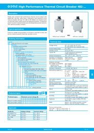
<strong>Thermal</strong> <strong>Overcurrent</strong> <strong>Circuit</strong> <strong>Breakers</strong> 2-<strong>5000</strong>/2-<strong>5700</strong>-...DimensionsTerminal design2-<strong>5000</strong>-P10-P10-A3 -K100.05...2.5 A15.197ø9.5.374A1 4 3 219.8.78031current rating in A1.22510.412.2 ON.409.48018.54418.2 OFF.728 1.73 .7177.276ø13.5.5312-<strong>5000</strong>-P10-A30.05...2.5 A14.5.571blade terminal DIN 46244-A6.3-0.8(QC .250)2-<strong>5000</strong>-P101 4 3 2 1 4 3 213.512operating area1 4 3 2Amax. 2.5max .0981 4 3 2mounting areaiG1=3/8-27UNS-2A tightening torque max. 1 NmiG2=M12x1 tightening torque max. 1.5 NmAø6.5.2562-<strong>5700</strong>-P10operating areaA25.98425.984Installation drawings10.4.409flat head screw M4x6 ISO1580tightening torque 1.2 Nm401.5750 131.97.512ø4.5.1772-<strong>5700</strong>-P1022.5.88616.5.65010.394OFFONmax. 2.5max .09846.51.831 4 3 219.8.780291.14D-shaped threadneck10.4.409blade terminalDIN 46244-A6.3-0.8(QC .250)current rating in A for standard(-DD version without push button marking)14.5.5711.0391 4 3 21.039mounting areamounting hole5iG1=8.8iG2=11.3iG1=.346iG2=.445SW 14.551iG1=ø9.6 -0.1iG2=ø12.2 -0.1iG1=.378 -.004iG2=.480 -.004iG1=8.9 -0.1iG2=11.5 -0.1iG1=.350 -.004iG2=. 453 -.004This is a metric design and millimeter dimensions take precedence ( mm )inch1 - 100www.e-t-a.comIssue A
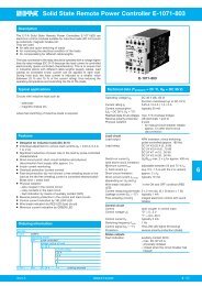
<strong>Thermal</strong> <strong>Overcurrent</strong> <strong>Circuit</strong> <strong>Breakers</strong> 2-<strong>5000</strong>/2-<strong>5700</strong>-...Internal connection diagrams0.05 ... 2.5 A(with or without shunt terminal)13 ... 25 A(without shunt terminal)1(3)1(-A3)22Typical time/current characteristics at +23 °C/+73.4 °F100000.05 - 2.7 A2.8 - 23 A100025 ATrip time in seconds1001010.11 2 4 6 8 10 20 40... times rated currentThe time/current characteristic curve depends on the ambient temperatureprevailing. In order to eliminate nuisance tripping, please multiply the circuitbreaker current ratings by the derating factor shown below. See alsosection 9 – Technical information.Ambient temperature °F -4 +14 +32 +73.4 +104 +122 +140°C -20 -10 0 +23 +40 +50 +60Derating factor 0.76 0.84 0.92 1 1.08 1.16 1.24This is a metric design and millimeter dimensions take precedence ( mm )inchIssue A www.e-t-a.com1 - 101