KORLOY CUTTING TOOLS
KORLOY CUTTING TOOLS
KORLOY CUTTING TOOLS
- No tags were found...

You also want an ePaper? Increase the reach of your titles
YUMPU automatically turns print PDFs into web optimized ePapers that Google loves.
<strong>KORLOY</strong> <strong>CUTTING</strong> <strong>TOOLS</strong>
How to use the Website on Mobile and Tablet PCAccess the internet on a smart phone. Get on the website ‘ http://m.korloy.com ’. or Type in the search word, ‘korloy’ in the search box. or Link the website with scanning the QR code.* Language selection (Korean/English) availableAccess the internet on a table PC. How to download QR code scan Application- Search ‘QR code scan’ in the Application download market.i PhoneAndroid smart phoneApp StoreAndroid MarketFree QR code scan Application- There are many software for QR code scan in the Internetand you can use any of them for downloading the Application.EggMon
<strong>KORLOY</strong> <strong>CUTTING</strong> <strong>TOOLS</strong>2012
<strong>KORLOY</strong><strong>CUTTING</strong> <strong>TOOLS</strong><strong>KORLOY</strong> Inc. is a total cutting tool manufacturer specializing inuncoated, coated (CVD, PVD), carbide and Cermet inserts.<strong>KORLOY</strong> Inc. was founded in 1966 and is now a top leadingcutting tool provider that constantly invests and improves itsR&D center in Korea.Our goal is to be the top, globally leading company that throughinnovation overcomes the continuous challenges of today andtomorrow.
C O N T E N T SGrades & Chip BreakersTurningMulti Functional ToolsThreadingABCDMillingEEndmillsFDrillsGBrazed ToolsHTooling SystemITooling ExamplesJPartsKTechnical InformationLOld-fashionedproduct informationMIndexN
SAFETY GUIDE OF CARBIDE PRODUCTS<strong>KORLOY</strong> Inc. is continuously trying to develop safer and higher quality productsPlease be aware of the safety guidelines below prior to using <strong>KORLOY</strong> Inc. products• It is generally accepted that the proper handling of cemented carbide tools requires awareness of safety asnoted above. For more information, please contact us.• <strong>KORLOY</strong> does not accept any responsibility for any accident caused by inappropriate use, abuse of tools, orchanges to the products.1. PL (Product Liability)In accordance with the PL (Product Liability) law, we have attached a WARNING label on the case of <strong>KORLOY</strong>products. There is no warning on the surface of the tools. Please read this safety guidelines before using carbidetools and provide safety education to all users.2. Basic characteristics of CEMENTED CARBIDE toolsCemented carbide tools are made of carbides, nitrides, carbonitrides, oxides of W, Ti, Al, Si, Ta, B etc and metalcomponent like Co,Ni, Cr, Mo as binder. Cemented carbides tools have high hardness and specific gravity.Generally there's no smell but according to usage and treatment, appreance and color could be changed3. Precaution for CEMENTED CARBIDE toolsSAFETY GUIDE OF CARBIDE PRODUCTS1) Cemented carbides are extremely hard and brittle at the same time.Impact shock or excessive clamping power could cause fracture or breaking of the tool.2) Cemented carbides have large sepcific gravity, thus they require special attention as a heavy material when youhandle big sizes or large quantities.3) Cemented carbides have different thermal expansion coefficient with steel and ferrous materials. Shrink fit orswell fit products may cause trouble if they are used at undesirable conditions like extremly high or lowtemperatures.4) There are several cemented carbide products having sharp cutting edges.Be careful not to handle the tools with bare hands which may cause cuts or injury, especiallywhen removing the tools from the case, do not touch the cutting edge and be careful not to drop it.5) Storing carbide tools in a corrosive atmosphere may cause erosion which can reduce toughness.6) Please refer to the catalouge safety guidance prior to handling the tools.7) Do not absue tools under inappropriate conditions.4. Precaution for machining (grinding, welding, EDM) of CEMENTED CARBIDE tools1) Surface condition can affect the toughness of the tool, so it is recommended to use a diamond grinding wheel.2) Grinding of cemented carbide creates mist and dust. It contains harmful compositions like Co, thus it isrecommended to use a mask, mist collection, and other protective facilities. If the dust gets in your skin or eye,rinse immeditely with continously running water.3) In case of grinding with coolant, coolant contains harmful metal components which cause environmentalproblems. Handle the coolant according to the manufacturer's recommendations.4) Check for cracks after re-grinding carbide tool and reuse.5) Marking with laser or electric pen may cause cracks on the carbide tool. The crack can shortened tool life.6) EDM of carbide may cause residual cracks on the carbide tool, so if necessary , remove the crack with agrinding process.7) Brazing of carbide tools at extremly high or low temperatures compare with the melting point of brazingmaterials may cause loosening or breakage.8) Overheating a oil base coolant may cause a fire or flames, thus be prepared for fire prevention.
SAFETY GUIDE OF CARBIDE PRODUCTS5. METAL<strong>CUTTING</strong> SAFETYDANGEROUS FACTOR· Sharp cutting edge of cutting tools may cut your bare-hand· Inappropriate conditions or usage may cause fragmentation and expelparts of tools which may cause injury· Severe load on tool and premature wear of cutting edge may bringexcessive cutting force on tool, causing fracture of the tool andmay cause injury· Chips evacuated during cutting are hot and sharp and maycause burns and cutsSAFETY COUNTERPLAN· Use gloves when pulling out the insert from the case or mounting iton the machine· Use glasses or safety cover for your safety· Use the tools within the recommended range· Please refer to catalogue and safety guidelines first.· Use glasses or safety cover for your safety· Change the tool as required before excessive wear or fracture· Use glasses or safety cover for your safety· Stop machining and put safety glove on and use a hook tool toremove chipsCutting tools· Touching the workpiece immediately after cutting may cause burns · Use gloves or safety cover for your safety· Be aware of sparks, fire, or explosion of hot chipsgenerated during the cutting operation· Do not use at the place where having explosive materials· Prepare for fire extinguishments· In case of high RPM machining, vibration and chattering may occurdue to the improper balance of the machine· Touching a burr remaining on the workpiece with a bare-handmay cause a cut· Use glasses or safety cover for your safety· Check first if there's any chattering, vibration or strange noisesprior to your main cutting operation· Do not touch the burr with bare-hand· Use gloves or safety cover for your safety· Loose clamping of the workpiece may cause the tool to fractureand result in damage to the cutter body and possible injury· Tools are operated to right-hand direction normally. Left-hand directionoperation can cause fracture of tool and body damage· Clamp the workpiece tightly· Do not use left-hand direction without notice· Check the package of product to check the availability ofleft-hand operationIndexable tools· Loose clamping of inserts and parts may result in ejection ofthe tool during cutting and may cause serious injury· Over loaded clamping of inserts by a lever (such as a pipe)may cause dangerous fracturing of parts and inserts· In case of high speed machining, parts and inserts can beforced out by centrifugal force· Check the clamping of inserts and parts prior to machining,and use original parts only· Do not use lever inappropriately· Use within recommended condition· Use glasses or safety cover for your safetyRotating toolsBrazedtools· Since cutter has sharp cutting edges touching with abare-hand may cause a cut· It is dangerous to use glove with rotating machine· Contact with body or clothes is dangerous with rotating parts· Vibration generated by balancing trouble may cause a fracture andejection of the tool which may cause serious injury· In case of drilling, the uncut bottom core can fly out of the partwith high speed and cause serious injury· Use gloves or safety cover for your safety· Do not wear gloves when you work with rotating machine· Keep your body and clothes away from rotating machine· RPM should be controled within recommended condition· Check the balance of rotating part periodically· Use gloves or safety cover for your safety· The edges of small diameter drill are sharp and easy to break · Use gloves or safety cover for your safety· Fragmentation and ejection of brazed carbide tip may cause injury· Check the brazed tip before using.· Do not use at high temperature cutting conditionSAFETY GUIDE OF CARBIDE PRODUCTS· There's a possibility of breaking the carbide tip after several brazing · Do not use brazing a tip that has been brazed several timesETC· Abusing may cause fragmentation of tool and is very dangerous. · Stick to safety regulations and guidelines
<strong>KORLOY</strong> Inc. Code SystemGrade Name for Coated CarbideCoatingNCCVDMachining Type0 1TurningPCPVD3Universal (Milling+Turning)5MillingNC 5 3 3 0Indication of WorkpieceSteel PCast iron KHeat resistance alloy for titanum SStainless steel MUniversal (P,M,K)36895ISO Grade0 1 ~ 5 0Wear Resistance ToughnessChip Breaker‘VISION’Series‘HARMONY’Series‘GREEN’SeriesVHGVFExternal(General Machining)External(Functional Machining)InternalHHeavy dutymachiningSStainlesssteelMPRRoughmachiningWWiperFPMMediummachiningAAluminum,Stainless steel(Finishing)C F UCopymachiningFinishmachiningFine finishmachiningMediummachining(Positive)Finishmachining(Positive)<strong>KORLOY</strong> Inc. Code SystemTerminology of tool formulaTERMTool diameterCutting speedRevolution per minuteFeed per minuteCODEDvcnvfUNITinchsfmmin -1ipmTERMHorse power requirementSpecific cutting resistanceTorqueThrustCODEPckcMcTcUNITkWMPaN.mNFeed per revolutionfniprCycle timetcminFeed per toothfziptTool lifeTminToothzFlank wearVBinchAxial depth of cutapinchCrater wearKtinchRadial depth of cutaeinchNose radiusrinchPeak feedpfinch
How to use E-catalogueContact with Korloy homepagehttp://www.korloy.com (Korloy homepage)http://ecatalogue.korloy.com (E-catalogue)Banner-icon click in homepageMain picture2 Search for categoryClick image by step andSearch for items1 Quick searchSearch without image6 AdministratorOnly administratorsmay access this menu7 Login/LogoutLogin, Logout & Registeras a member here8 e-mail inquiryContact the personin charge for furtherinformation by e-mail3 Search fordesignationSearch for Holder,Insert, Parts, grade9 My favoriteYou can organizeshortcuts on your favoriteitems(registered memberonly)10 MemoYou can save short texthere4 HomeMove to home5 Select languageKorean-Metric, English-Metric, English-inch type11 Search historyYou can check yoursearch history hereScreen shot• Screen shot 1 • Screen shot 2122 313445How to use E-catalogue5 61. Step : Select category product and check product detail2. Print : Print current detail3. Designation : Click designation to check available insert4. DXF : Open or Save DXF file5. Search : Search product by designation6. Favorite : Select product and click this icon to add favorite1. Category : select holder, insert or grade2. Section : Select one out of list3. Condition : Select one out of list4. Search : Search in selected caterogy5. Close : Close quick search menu
How to use Tool4U (Web quotation requriement)Contact with Korloy homepagehttp://www.korloy.com (Korloy homepage)http://ecatalogue.korloy.com (E-catalogue)Clickbanner-icon on the web siteMain page1 Semi standardStandard but different in size3 Special ToolingFor special tollingsuch as gear, edgemiller, railway, nonstandardindexable& facemill2 Tailor-madeStandard nokorloy item4 Custom-tailoredCustomized item byspecial request5 SearchYou can search bydesignation7 AdministratorOnly administratorsmay access thismenu8 Login/LogoutLogin, Logout& Register as amember here9 My favoriteYou can organizeshortcuts on yourfavorite items(registered memberonly)10 MemoYou can save shorttext here11 My quotationYou can check yourquotation list hereHow to use Tool4U (Web quotation requriement)6 HomeClick here to go onto the mail pageScreen shot• Screen shot 1 : step3. Product detail142 3• Screen shot 2 : Size input page12 HelpFunctionaldescription of eachmenu1. Step : Select category, product and check product detail2. Next step : Open new window for changing dimension3. Print : Print current page4. Search : Search product by designationEnter essential information needed to quoteand click “Quote” button to send e-mail
AGRADES & CHIP BREAKERSKorloys new grades are designed with optimal substrates for each application and are PVD coatedfor high temperature, high hardness and oxidation resistance, or CVD coated for hightempeure and wear resistance. Additionally, the improved post-coating treatment providessuperior surface finishes to ensure the highest levels of quality and productivity.CHIPC O N T E N T SGradesA02Korloy grades systemTurning GradesA03 Turning grade selectionsA04 CVD coated gradesA08 PVD coated gradesA10 Uncoated gradesA11 Cermet gradesA12 Coated Cermet gradesMilling GradesA14 Milling grade selectionsA15 CVD coated gradesA17 PVD coated gradesA19 Uncoated gradesA20 Milling Cermet grades
GRADES &BREAKERSChip BreakersSolid Endmills &Solid Drills GradesA21A22A23Solid Endmills gradeselectionsUltra fine cementedcarbide gradesSolid Drills gradeselectionsOthers(turning/milling/endmills)A24A25A28Diamond coatedDLC coated gradesCBN gradesPCD gradesA29A31A32Chip Breaker For TurningChip Breaker For MillingChip Breaker For DrillingGrades &Chip Breakers
AGradesKorloy grades systemUncoatedcarbideP Steel ST05 ST10 ST15 ST20 ST30A ST30N ST30 ST40 ST45 ST46M Stainless steel U10 U20 ST30A U40K Cast iron H02 H01 H05 H10 G10N Non-ferrous metal H01Coatedcarbidefor turningPMKSSteelStainless steelCast ironHRSANC3010 NC3220 NC3120 NC3030PC8110 NC9025 PC5300 PC9030NC6205 NC6210 NC315K NC5330 PC5300PC8110 NC5330 PC5300NC5330 NC500HCoatedcarbidefor millingPMKSSteelStainless steelCast ironHRSANC5330 NCM325 PC3600 PC5300 NCM335 PC3545NC5330 PC5300 PC9530 PC3545PC8110 PC6510 PC5300 NC5330PC5300 PC3545Coated carbidefor Drills, EndmillsCoatedUncoatedGeneral General PC203F PC205F PC210FPC210A PC215F PC220 PC210 PC210C PC221F PC230FH01 FS1 FA1 FA2 FG2 FCCCuttingToolTurning CermetMilling CermetPKPSteelCast ironSteelCN1000 CN2000 CN20 CN30CN1000CC105 CC115 CC125Coated cermetPSteelCN2000CN20CN30cBNP Steel KB320 KB330 KB350 KB360K Cast iron KB410 KB350 KB370S HRSA KB370H Hardened steel KB410 KB420 KB425 DNC250 KB320 KB330 KB370PCDN Non-ferrous metal DP90 DP150 DP200DiamondCoatingNTurningMillingEndmillsND1000ND2000ND3000Application rangeGradesDLCCoatingNTurningMillingEndmillsPD1000PD2000PD3000Grades &Chip BreakersA2WearresistanceToolMiningToolUltra fine graincemented carbideUncoatedcarbideUncoatedcarbideZUltra fine graincementedFS1 FA1 FCCcarbideV Wear parts D1 D2 D3 G5 G6 K20GI Corrosion resistance IN10 IN20 IN40E General GR10 GR20 GR30 GR35 GR40 GR50
GradesAThe best way to choose <strong>KORLOY</strong> turning insertsSelection systemWorkpieceISOP Steel M Stainless steel K Cast iron N Nonferrous S HRSA H HardenedP01 P10 P20 P30 P40 P50 M10 M20 M30 M40 K01 K10 K20 K30 N10 N20 N30 S01 S10 S20 S30 H01 H10 H20NC3010PC8110NC6205ND1000PC8110PC8110CoatedcarbideNC3220NC3120NC3030NC5330NC9025PC5300PC9030NC6210NC315KNC5330PD1000NC5330PC5300NC500HPC5300CN1000CN1000CermetCN2000CN20cBN / PCDKB350KB360DP150KB320KB330ST05U10H02H01H01ST10U20H01UncoatedcarbideST15ST20ST30NST40U40H05H10G10ST30ST46ST45Application range of turning gradesPSteelMStainless steelKCast ironNNon-ferrous metalSHeat resistant alloyHHardened SteelGradesvc(sfm)vc(sfm)vc(sfm)vc(sfm)vc(sfm)fn(ipr)fn(ipr)fn(ipr)vc(sfm)Grades &Chip Breakersfn(ipr)fn(ipr)fn(ipr)A3
ATurning GradesCVD coated GradeGrade for all applications of steelNC3220NC3220 covers a wide application range for all kinds of steels (carbon steel, alloy steel, forged steel, rolled steel, tool steel, mildsteel, bearing steel and other special steels) in both continuous and interrupted machining.New substrate and new coating layer with good wear resistance provides longer tool life preventing plastic deformation in highspeed and high temperature machining.Improved coating layer with superior adhesion and new surface treatment provides excellent welding resistance and chippingresistance that leads to stability of machining and improvements in productivity .Increased lubrication of coating layer improves the surface finish and reduces the cutting load to increase wear resistance.Coating structureTiN layer with good surface roughness and weldingresistance layer with oxidation resistance at high temperatureand plastic deformation resistance.Bonding layer with excellent chipping resistance due toimproving adhesion.Fine columnar MT CVD-TiCN with toughness and wearresistance.Exclusive substrate material for coating improvingwear resistance.BeforeAfterNew technology of surface treatment improves weldingresistance and stability in machining.CVD turning grade for Cast ironNC6205NC6210 K-Power coating NC6205 - Superior cutting performance in continuous and high speed machining. NC6210 - Stable tool life in continuous and interrupted turningFeaturesA coating layer for goodsurface finish and wear resistance.Turning GradesBCSpecial bonding layer foradhesion strength of each layer.Fine columnar CVD MT TiCN withimproved toughness and hardnessExclusive substrate for cast iron machining.Grades &Chip BreakersA4K-Power coatingOutermost layer layer with superiorlubrication guarantees wearresistance and chippingresistance in high speedmachining.Bonding layer (betweenMT-TiCN and A 2O3 layer)Special bonding layer withsuperb adhesion strengthimproves flaking resistanceand chipping resistance.
Turning GradesASelection systemWorkpieceMachiningtypesRecommendedgradeRecommendedcutting speed(sfm)ISOApplication rangePMKSSteelStainlesssteelCast ironHRSAContinuouscuttingInterruptedcuttingContinuous cuttingInterrupted cuttingContinuouscuttingInterruptedcuttingContinuous cuttingContinuous cuttingNC3010NC3220NC3120NC3030NC5330NC500HNC9025NC6205NC6210NC315KNC5330NC5330984 (656~1312)918 (590~1246)820 (492~1148)656 (492~820)623 (328~755)328 (164~492)459 (262~722)886 (492~984)1148 (820~1476)656 (492~820)591 (427~755)623 (328~754)P01P10P15P20P30P35P40M30M40K05K10K20K30S20S30NC3010NC6205NC3220NC9025NC6210NC5330NC3120NC3030NC315KNC5330NC5330NC500HThe features of CVD turning gradesCVD Coated gradesISOFeaturesNC3010P05 ~ P15• High speed cutting for steel• Combining excellent wear resistance substrate with chipping and heat resistance increased stability• MT-TiCN + A2O3 + TiNNC3220P15 ~ P25• For medium machining of steel• Universal grade combining substrate with wear resistance and toughness and coating with oxidation resistanceand fracture resistance • Special treatment on the outermost layer• MT-TiCN + A2O3 + TiNNC3120P15 ~ P25• Medium to roughing for steel• Combining excellent fracture resistance substrate with chipping resistance and heat resistance increased stability• MT-TiCN + TiC + A2O3NC3030P25 ~ P35• For general cutting, interrupted cutting and roughing operations in steel and stainless steel• Combining excellent fracture resistance substrate with chipping resistance and heat resistance increasedstability in wide ranges of cutting conditions• MT-TiCN + TiC + A2O3 + TiNNC5330NC9025NC500HP30~P40M25~M35K15~K25S15~S25M25 ~ M35P25 ~ P35• stainless Steel/General Cutting for Mild Steel & Forging Steel• MT-TiCN + + TiN• stainless Steel/General Cutting for Mild Steel & Forging Steel• MT-TiCN + + TiN• Heavy interrupted cutting for steel• Plastic deformation and fracture resistance substrate with chipping resistance and heat resistance increasedstability in wide ranges of cutting conditions• MT-TiCN + TiC + + TiNTurning GradesNC6205NC6210NC315KK01 ~ K10K05 ~ K15K10 ~ K20• General cutting for gray cast iron and ductile cast iron• High hardness substrate and improved adhesion of thick show superior wear resistance• MT-TiCN + • General cutting for gray cast iron and ductile cast iron• Tough substrate and improved adhesion of thick show superior wear resistance• MT-TiCN + • Interrupted cutting and high-efficiency machining for cast iron• Tough substrate and improved adhesion of thick show superior wear resistance• MT-TiCN + + TiNGrades &Chip BreakersA5
ATurning GradesCutting performance (NC3220)PAlloy Steel (5120H, hot forging)PCarbon Steel(1040, cold forging)Cutting conditionDesignationvc(sfm) = 1,180~1,410fn(ipr) = 0.008ap(inch) = 0.048~0.06(external machining/facing)wetINSERTHOLDORCNMG432-VCPCLNR16-4DCutting conditionDesignationvc(sfm) = 918fn(ipr) = 0.008~0.010ap(inch) = 0.04dryINSERTHOLDORCNMG433-VCPCLNR16-4DTest resultCutting pass / conner379320NC3220 CompetitorØ3.0 3.1Ø0.8Test resultCutting pass / conner2501504.7NC3220 CompetitorPAlloy Steel (4130H, hot forging)PCarbon Steel(S53C, cold forging)Cutting conditionDesignationvc(sfm) = 262~1,640fn(ipr) = 0.006~0.012(External machining/facing /grooving/taping)ap(inch) = 0.028~0.006wetINSERTHOLDORDNMG442-VCPDJNR16-4D Cutting conditionDesignationvc(sfm) = 918fn(ipr) = 0.008~0.010(External machining / internal machining)ap(inch) = 0.04dryINSERT DNMG442-VCHOLDOR PDJNR16-4DTest resultØ1.2Test resultCutting pass / conner1396.9Cutting pass / conner2501504.76.3NC3220 CompetitorNC3220 Competitor3.1Turning GradesGrades &Chip BreakersPAlloy Steel (SCR cold forging)Cutting conditionDesignationTest resultCutting pass / conner105100vc(sfm) = 1,030fn(ipr) = 0.010(external machining/facing)ap(inch) = 0.04wetINSERTHOLDORØ3.5CNMG432-VM PCLNR16-4D1.6A6NC3220 CompetitorØ7.1
Turning GradesACutting performance (NC6205 / NC6210)KGray cast iron(GG25), in high speed machiningKDuctile cast iron(GGG600), in interrupted machiningCutting conditionDesignationvc(sfm) = 1.980fn(ipr) = 0.012ap(inch) = 0.059dryContinuous external machiningINSERTHOLDERCNMA423(NC6205, NC6210) DCLNL20-4DCutting conditionDesignationvc(sfm) = 396fn(ipr) = 0.012ap(inch) = 0.059wetInterrupted facingINSERTHOLDERCNMA432(NC6205, NC6210) DCLNL20-4DTest resultWear(inch)0.0120.0100.0080.0060.0040.002Competitor K10Competitor K05NC6210NC6205Test resultCutting time(min)654321WearFractureWearFractureØ7.90 00 1 2 3 4 5Machining time(min)NC6210CompetitorK10NC6205CompetitorK05KGray cast iron(GG25), Blake DiscKGray cast iron(GG25), NippleCutting conditionvc(sfm) = 1,287fn(ipr) = 0.010ap(inch) = 0.079wetCutting conditionvc(sfm) = 1,155fn(ipr) = 0.010ap(inch) = 0.028wetDesignationINSERTHOLDERCNMG433-VK(NC6210) PCLNR16-4DDesignationINSERTHOLDERCNMG432-VK(NC6210) PCLNR16-4DTest resultTest resultCutting pass / conner8050Cutting pass / conner11Ø11 8Ø5.1NC6210Competitor K05NC6210Competitor K10KDuctile cast iron(GGG50), ShaftCutting conditionvc(sfm) = 660fn(ipr) = 0.011ap(inch) = 0.079wetTurning GradesDesignationINSERT WNMG0433-VK(NC6205) HOLDER DWLNL16-4DTest resultCutting pass / conner9380Ø1.2Grades &Chip BreakersNC6205Competitor K10A7
ATurning GradesPVD coating GradePVD Coated grade for stainless steel and HRSA.PC8110Micro grain carbide minimizes chipping of the cutting edge due to enhanced edge strength Latest PVD coating technology with high hardness and high temperature oxidation resistance PC8110 provides high productivity during machining HRSA material in high speed, high feed cuttingconditionsPVD turning grade for stainless steel and HRSAPC5300 High efficiency during machining of carbon steel / cast iron / stainless steel / HRSA Stable machining due to specific carbide substrate with strong toughness and highhardness that reduces fracture by chipping Excellent wear resistance due to special PVD coating film with oxidation resistance,thermal stability, and surface smoothnessCoating structureOutermost layerInnermost layerImproving high temperatureoxidation resistance,high hardnessImproving adhesion offilm layer for chippingresistanceLatest PVD coating technologydeveloped by <strong>KORLOY</strong>New concept of coatingwith high temperatureoxidation resistance and highhardnessSub micron toughest carbideSelection systemWorkpieceMachining typesRecommendedgradeRecommendedcutting speed(sfm)ISOApplication rangeTurning GradesPMSSteelStainlesssteelHRSAContinuous cuttingInterrupted cuttingContinuous cuttingInterrupted cuttingContinuous cuttingInterrupted cuttingPC5300 394~722 (492)PC8110PC5300PC9030PC8110PC5300492~820 (656)394~722 (158)164~591 (394)131~295 (197)98~230 (164)P30P40M10M20M30M40S10S20S30PC8110PC8110PC5300PC5300PC5300PC9030The features of PVD coated gradesPVD Coated gradesISOFeaturesGrades &Chip BreakersA8PC9030PC8110PC5300M30~M40M10~M20S10~S20P30~P40M20~M30K20~K25S20~S30• Medium,roughing and heavy interrupted cutting for stainless steel• TiAN coating and ultra fine grain substrate adopted• High chipping and welding resistance for stable machining• High speed and continuous machining for stainless & HRSA• High chipping and welding resistance longer tool life• New TiAN coating and ultra fine grain substrate adopted• Universal grade for stainless,HRSA,steel and interrupted cast iron machining• High chipping and welding resistance for longer tool life• New TiAN coating and ultra fine grain substrate adopted
Turning GradesACutting performance (PC8110 / PC5300)SInconel (N07718)CuttingconditionDesignationvc(sfm) = 197fn(ipr) = 0.008ap(inch) = 0.08wet(4min machining) CNMG432-GS DCLNR16-4DWear(inch)Test result0.0080.0060.0050.0030.0020Competitor BCompetitor APC81101 2 3 4 5Machining time(min)PC8110Competitor ACompetitor BSTitanium alloy (Ti-6Al-4V)CuttingconditionDesignationvc(sfm) = 230fn(ipr) = 0.008ap(inch) = 0.04wet(8min machining) CNMG432-HA DCLNR16-4DWear(inch)Test result0.0080.0060.0050.0030.0020Competitor BCompetitor APC81102 4 6 8 10Machining time(min)PC8110Competitor ACompetitor BMSStainless steel+Stellite (316+R30006) S Inconel 625Cutting conditionvc(sfm) = 197fn(ipr) = 0.008ap(inch) = 0.08Cutting conditionvc(sfm) = 197fn(ipr) = 0.008ap(inch) = 0.08Designation CNMG432-GS DCLNR16-4DDesignation DNMG442-HSDDLNL16-4DTest resultTest resultCutting pass / conner3010 (broken)Ø12Cutting pass / conner108Ø8PC8110Competito(M30)PC8110 Competito(M10)MStainless steel (304) M Stainless steel (316)Cutting conditionvc(sfm) = 925fn(ipr) = 0.008ap(inch) = 0.12wetCutting conditionvc(sfm) = 394fn(ipr) = 0.008ap(inch) = 0.02~0.06wetTurning GradesDesignationTest resultCutting pass / conner60 328 Ø2CNMG432-HSDCLNR16-4DØ1DesignationTest resultCutting pass / conner1 Ø12SNMG432-GSDCLNR16-4DGrades &Chip BreakersPC8110Competito(M30)PC8110Competito(M30)A9
ATurning Grades<strong>KORLOY</strong> Uncoated Carbide GradesFeatures Korloy’s uncoated cemented carbides are designed to optimizemachining with uniform quality. Furthermore, Korloy’s cementedcarbides are manufactured with the highest quality tungsten carbides,cobalt, and refractory carbides (TiC,TaC) to produce superiortoughness and wear resistance[ Microstructure ]AdvantagesP.M.K cemented carbide can be applied for various workpieceExcellent thermal crack resistance makes it possible to machine inwet cutting conditionsFine grain and minimizing chemical affinity to workpieceSpecially designed by KorloyHigh toughness and low cutting forcePSelection systemKPKWorkpieceSteelCast ironAlloyed aluminumAlloyed copperRecommendedgradeST10ST15ST20ST30AH02H01, H05H10, G10H01H01Recommendedcutting speed(sfm)492 (328~656)459 (295~623)427 (230~591)427 (230~591)492 (328~656)459 (328~656)427(295~623)1640 (984~2625)656 (492~984)ISOP10P20P30K01K10K20K30ST10H02Application rangeST15ST20H01H05H10ST30AG10Main applicationISOCompositionFeaturesWorkpiecePWC-TiC-TaC-CoHeat resistance, excellent plastic deformation resistanceCarbon steel, Alloy steel, Stainless steelMWC-TiC-TaC-CoGeneral tools stable heat resistance with strengthCarbon steel, Alloy steel, Stainless steel, Cast steelKWC-CoHigh strength and superior wear resistanceCast iron, Non-ferrous metal, Plastic, etcProperties of Uncoated CarbideTurning GradesISOPGradeST05ST10ST20Hardness(HRA)92.792.191.9TRS(kgf/mm 2 )140175200Youngs modulus(10 3 kgf/mm 2 )-4856Thermal expansioncoefficient(10 -6 /)-6.25.2Thermal conductivity(cal/cmsec)-2545ST30A91.3230535.2-U1092.417047--Grades &Chip BreakersMKU20ST30AA40H02H0191.191.389.293.292.9210230270185210-53-6166-5.2-4.44.788--105109A10G1090.9kPa = 102kgf/m 2 , 1W/mk = 2.39×10 -3 cal/cm·sec·℃25063-105
Turning GradesACermet GradeFor steel, cast iron, other sintering alloy steel(P10, K10)Continuous cutting exclusive cermetCN1000Functionally gradient cermet materialization leads to excellent quality on both groundand non-ground insertsDue to increase of plastic deformation resistance, it maintains superior wear resistanceand precision on workpiece dimension over long period usage with wet and dry cuttingconditionsImproved adhesion wear resistance on upper part and cutting edge, reduces tool scutting load and makes surface finishing smooth after machiningNew cermet grade for finishing of cast iron, carbon steel, alloy steel, and other sinteredsteels[ Microstructure of Ticn-based cermets]SurfaceSelection systemCoreWorkpieceP SteelK Cast ironMachiningtypesContinuous cuttingInterruptedcuttingFinishingRecommendedgradeCN1000CN20CN2000CN1000Recommendedcutting speed(sfm)919 (492~1312)689 (394~984)919 (492~1312)ISOP10P20K01K10CN1000CN1000Application rangeCN20CN2000The features of <strong>KORLOY</strong> main cermet gradeCermetISOFeaturesCN1000P05 ~ P15 / K05 ~ K10High hardness cermet for steel, cast iron, sintered metalFunctionally gradient material cermet as a next generation cermetCN2000P10 ~ P20• Wide ranges from finishing to roughing in steel machining• Functionally gradient material cermet as a next generation cermetCN20P10 ~ P20• For general turning and milling for steel• General purpose grade provided with both wear resistance andtoughnessTurning GradesProperties of cermetISOGradeHardnessTRSSpecific GravityPKCN1000CN2000CN20CN1000< 1900< 1800< 1600< 1900< 180< 210< 220< 1806.5~7.56.8~7.06.7~7.06.5~7.5Grades &Chip BreakersA11
ATurning Grades<strong>KORLOY</strong> Coated Cermet GradesFeatures Impact resistance and superior toughness substrateprevents chipping and fracture at the initial stageensuring longer tool lifeLubricant coating layer improves chip flow and reducesinsert loadHigh hardness, smoothcoating, Lubricant layerTough substrateSelection systemWorkpieceMachiningtypesRecommendedgradeRecommendedcutting speed(sfm)ISOApplication rangePSteelContinuous cuttingInterruptedcuttingCC105CC115CC1251148 (820~1476)919 (755~1312)755 (492~984)P05P10P20CC105CC115CC125The features of <strong>KORLOY</strong> coated cermet gradeCoated cermet ISO FeaturesCC105P01 ~ P10• PVD coated Cermet• Light cutting for steel and cast iron in high speed machining• Optimized for precision boringCC115P10 ~ P20• PVD coated Cermet• Light cutting for steel and cast iron in medium or high speed machining• Dry and wet cutting are availableCC125P15 ~ P25• PVD coated Cermet• High toughness cermet for millingGrades &Chip BreakersTurning GradesA12
Turning GradesACutting performance(CN1000)PCarbon steel (1045)PCarbon steel (1045)Cutting conditionDesignationTest resultvc(sfm) = 1312fn(ipr) = 0.008ap(inch) = 0.04 CNMG432-VG PCLNL16-4DWear(inch)0.0130.0110.0090.0070.0050.0030.001CompetitorCN1000Cutting conditionDesignationTest resultTool life (%)120%100%vc(sfm) = 820fn(ipr) = 0.004ap(inch) = 0.04wetØ2Ø1VNMG331-VG MVQNR16-3D05 10 15 20Machining time(min)CN1000CompetitoOuter boring partPAlloy steel (4130)CN1000CompetitorCutting conditionvc(sfm) = 820fn(ipr) = 0.007ap(inch) = 0.02wetKCast iron (No35B)Cutting conditionvc(sfm) = 984fn(ipr) = 0.008ap(inch) = 0.04DesignationTest resultTool life (%)130%100%Ø4DCMT32.51-C25 SDJCR12-3BØ2DesignationCNMG432-B25 PCLNR20-12CN1000 CompetitoFacingTest resultWear(inch)0.0130.0110.0090.0070.0050.0030.0010Competitor BCompetitor ACN10003 6 9 12 15 18 21Machining time(min)PSintered ferrous metalsCutting conditionvc(sfm) = 1109fn(ipr) = 0.008ap(inch) = 0.02wetTurning GradesCN1000Competitor ACompetitor BDesignationTest resultTool life (%)140%100%Ø6CNMG432-B25 PCLNR20-12Ø3Grades &Chip BreakersCN1000CompetitoFacingA13
AMilling GradesThe best way to choose <strong>KORLOY</strong> Milling insertsSelection systemWorkpieceISOP Steel M Stainless steel K Cast iron N Nonferrous S HRSA H HardenedP01 P10 P20 P30 P40 P50 M10 M20 M30 M40 K01 K10 K20 K30 N10 N20 N30 S01 S10 S20 S30 H01 H10 H20NC5330NC5330ND2000PC210FCoatedcarbideNCM325PC3600PC5300NCM335NCM325PC5300PC9530NCM335PC8110PC6510PC5300PD2000PC5300PC3545PC3545PC3545NC5330CN2000CermetCN20CN30cBN / PCDDP150KB360KB350ST20H01H01UncoatedcarbideST30AST30NU10U20H05H10ST40U40G10Application range of Milling gradesPSteelMStainless steelKCast ironPSteelMStainless steelKCast ironPVDGrades &Chip BreakersMilling GradesNNon-ferrous metalSHeat resistant alloyHHardenedvc(sfm)vc(sfm)vc(sfm)vc(sfm)CVDvc(sfm)vc(sfm)vc(sfm)fz(ipt)fz(ipt)fz(ipt)vc(sfm)vc(sfm)fz(ipt)fz(ipt)fz(ipt)A14fz(ipt)fz(ipt)fz(ipt)
Milling GradesACVD Coated gradeCVD Coated grade for stainless steel and soft steelNC5330Tough carbide, smooth coating for improved tool lifeBuilt-up-edge resistance, notch wear resistance, and the toughness have been improvedOutstanding performance for stainless steel machiningExcellent for machining sticky, soft steels, and forged steelsSuperior tool life for machining hard to cut material such as inconel and stelliteCoating structureTiN film : Smooth surface roughness andsuperior anti built-up-edgeFine columnar TiCN film : Optimimaltoughness and hardnessToughest dedicated carbide substrateemployed film : Excellent oxidation resistanceSelection systemWorkpieceMachining typesRecommendedgradeRecommendedcutting speed(sfm)ISOApplication rangeContinuous cuttingNC5330886 (722~1050)P15P20NC5330PSteelContinuous cuttingNCM325820 (492~984)P25P30NCM325Interrupted cuttingNCM335755 (394~919)P35P40NCM335MStainlesssteelContinuous cuttingContinuous cuttingInterrupted cuttingNC5330NCM325NCM335656 (492~820)591 (459~755)558 (394~689)M10M20M30M40NC5330NCM325NCM335KCast iron Continuous cutting NC5330 558 (427~722)The features of CVD Milling gradesK20K30NC5330Milling GradesCVD Coated gradesFeaturesNC5330NCM325NCM335P15 ~ P25M10 ~ M20K10 ~ K20P20 ~ P30M20 ~ M30P30 ~ P40M30 ~ M40• For high speed milling of steel and stainless steel• Superior wear resistance and chipping resistance grade for steel and stainless steel• MT-TiCN + A2O3 + TiN• For high speed milling of steel and stainless steel• Optimized grade for steel & stainless steel by employing proper substrate and hard coating• MT-TiCN + A2O3 + TiN• For interrupted and rough milling of steel and stainless steel• Toughest substrate with hard coating provides stable cutting and tool life for severe interrupted cutting• MT-TiCN + A2O3 + TiNGrades &Chip BreakersA15
AMilling GradesCutting performance(NC5330)PAlloy steel (4140)PAlloy steel [4140(H)]Cutting conditionvc(sfm) = 820fz(ipt) = 0.012ap(inch) = 0.08dryCutting conditionvc(sfm) = 427fz(ipt) = 0.012ap(inch) = 0.138dryDesignationINSERTCUTTERSDKN53AESN-SU ADNA5500RDesignationINSERTHS004072Test resultTest resultNC5330CompetitorCutting pass/ conner600550NC5330 Competitor(P30)PStainless steel (304) K Ductile cast iron (80-55-06)Cutting conditionvc(sfm) = 492fz(ipt) = 0.01ap(inch) = 0.08dryCutting conditionvc(sfm) = 656fz(ipt) = 0.008ap(inch) = 0.197dryDesignationINSERTCUTTERSDKN53AESN-SU ADNA5500RDesignationINSERT SDKN53AESN-SUCUTTER ADNA5400RTest resultTest result NC5330 CompetitorCutting pass/ conner2NC53301Competitor(P30)Milling GradesPcarbon steel (1045)Cutting conditionvc(sfm) = 902fz(ipt) = 0.005ap(inch) = 0.276wetKGray cast iron (No55B)Cutting conditionvc(sfm) = 1165fz(ipt) = 0.006ap(inch) = 0.197dryDesignationINSERTCUTTERTNMX2710AZNR-NM PBAM5125R-MDesignationINSERTCUTTERSPKN53EDSR-SU ADNA5400RGrades &Chip BreakersATest resultCutting pass/ conner65NC5330 Competitor(P30)Test resultCutting pass/ conner3NC53302Competitor(P30)16
Milling GradesAPVD coating GradePVD new grade for steel millingPC3600(SU/MU) Coating layer with high hardness and oxidation resistance at high temperature ensures stable tool life. Superior wear resistance and impact resistance in high speed machining of P grade materialsUniversal PVD GradePC5300 High efficiency during machining for carbon steel / cast iron /stainless steel / HRSA Stable machining due to specific carbide substrate with strongtoughness and high hardness that restrains fracture by chipping Excellent wear resistance due to special coating film with oxidationresistance, thermal stability, and surface smoothnessCoating structureOutermost layerInnermost layerImproving high temperatureoxidation resistance,high hardnessImproving adhesion offilm layer for chippingresistanceLatest PVD coating technologydeveloped by <strong>KORLOY</strong>New concept of coatingequipped with hightemperature oxidationresistance and high hardnessSub micron toughest carbideSelection systemWorkpieceMachining typesRecommendedgradeRecommendedcutting speed(sfm)ISOApplication rangePMSteelStainlesssteelContinuous cuttingInterrupted cuttingContinuous cuttingInterrupted cuttingPC3600PC5300PC3545PC5300PC9530PC3545656 (492~820)394 (328~492)394 (328~492)427 (164~656)394 (328~492)P20P30P40P50M20M30M40PC3600PC5300PC5300PC9530PC3545Milling GradesKSHCast ironHSRAHigh hardnesssteelContinuous cuttingInterrupted cuttingContinuous cuttingInterrupted cuttingContinuous cuttingPC8110PC6510PC5300PC5300PC3545PC210F820 (656~1312)656 (492~820)541 (394~689)230 (131~328)164 (98~230)820 (492~984)K01K05K10K20S20S30H01H10PC8110PC5300PC210FPC6510PC3545PC5300Grades &Chip BreakersA17
AMilling GradesThe features of PVD coated gradesPVD Coated gradesPC3600PC3545PC5300PC8110PC6510PC9530PC210FISOP20 ~ P30P35 ~ P45P30~P40S20~S25M20~M30K10~K20K01~K10K05~K15M20 ~ M35H01~H10Features• Milling grade for medium and roughing of steel• New coating layer with superior wear resistance and oxidation resistance with hightoughness substrate• TiAN / New coating • Grooving, Cutting, Milling• Medium and rough milling for steel.• Enhanced chipping resistant substrate.• K-Gold coating• Superior universal grade for steel, cast iron, hard to cut material, stainless steel• New coating and ultra fine grain provide wear resistance and oxidation resistance• For turning, milling, grooving, parting, drilling, and threading• Medium and rough cutting for hard to cut material and stainless steel• Superior wear resistance for finishing cast iron• New coating and ultra fine grain provide wear resistance and oxidation resistance• For turning, milling, grooving, parting• High speed milling grade for cast iron and aluminum.• K-Gold coating• Milling grade for cast iron and aluminum in medium to low cutting speed.• The toughest sub-micron substrate provides excellent cutting performance at high feed.• TiAlN coating• For milling, drilling• High speed milling grade for hardened steel , cast iron, and stainless steel(lLaser Mill)• New coating and ultra fine grain provide wear resistance and oxidation resistance• EndmillingCutting performance (PC3600)PA283-C P 4130Cutting conditionvc(sfm) = 708fz(mm/t ) = 0.0156ap(inch) = 0.04dryCutting conditionvc(sfm) = 748fz(ipt) = 0.006ap(inch) = 0.04dryDesignationINSERTCUTTERTPKN43PDSR-SU PPNA4500RDesignationINSERTCUTTERSDKN53AESN-SU ADNA51200RTest resultTest result12Milling GradesPCutting pass/ conner1210PC3600 Competitor1045 P D2Cutting condition47vc(sfm) = 1004fz(ipt) = 0.005ap(inch) = 0.08dry31Cutting pass/ conner1513PC3600 CompetitorCutting condition19vc(sfm) = 656fz(ipt) = 0.008ap(inch) = 0.08dry6Grades &Chip BreakersDesignationTest resultCutting pass/ conner64INSERTCUTTER24SDKN42AESN-SU ADNA41200R47DesignationINSERTCUTTERTest result (340min machining) A18PC3600 CompetitorPC3600Competitor
Milling GradesACemented Carbide GradesFeatures Due to Korloys advanced sintering technology, our uncoatedcarbide grades have a fine alloy structure which is necessaryto get superior quality from a uncoated cutting tool[ Microstructure ]AdvantagesSelection systemConsist of P,M,K carbide grades and can be used in all kinds of workpieceExcellent quality at machining with coolant, due to the superior thermalcrack resistance of the carbideDue to the special design of carbides, it has fine micro structure and lowaffinity with workpieceIt has excellent toughness and produces lower cutting loadsWorkpieceGradeRecommended cuttingspeed(sfm)ISOApplication rangePSteelST30A427 (230~591)P30ST30AKCast ironAluminum alloyCopper alloysH01, H05H10, G10H01H01492 (328~656)459 (295~623)1640 (984~2675)656 (492~984)K01K10K20K30H01H05G10Main composition and application rangeISO Composition Features WorkpiecePMKWC-TiC-TaC-CoWC-TiC-TaC-CoWC-CoExcellent thermal shock resistance andplastic deformation resistanceGeneral grades with thermal shockresistance and hardnessHigh hardness and superior wearresistanceCarbon steel, Alloy steel, Stainless steelCarbon steel, Alloy steel, Stainless steel,Cast steelCast iron, Non-ferrous metal, Non metalThe physical properties of gradesISOPGradeST05ST10ST20Hardness(HRA)92.792.191.9TRS(kgf/mm 2 )140175200Youngs modulus(10 3 kgf/mm 2 )-4856Thermal expansioncoefficient(10 -6 /)-6.25.2Thermal conductivity(cal/cmsec)-2545Milling GradesST30A91.3230535.2-U1092.417047--MKU20ST30AU40H02H0191.191.389.293.292.9210230270185210-53-6166-5.2-4.44.788--105109Grades &Chip BreakersG1090.9kPa = 102kgf/m 2 , 1W/mk = 2.39×10 -3 cal/cm·sec·℃25063-105A19
AMilling GradesMilling Cermet GradesFeatures High hardness substrate ensures long tool life in high speed milling. High toughness cutting edge ensures long tool life even in high impact machining. Chemically stable substrate provides excellent surface finish of the workpiece.Selection system• Application rangeWide application range: carbon steel(from soft steel to high carbon steel), alloy steel,hardened steel(especially KP4M, NAK80), tool steel(STD61 and others)Workpiece Machining types GradeRecommended cuttingspeed(sfm)ISOApplication rangePSteelContinuous cuttingContinuous cuttingInterrupted cuttingCN2000CN20CN30820 (656~984)591 (427~755)492 (328~656)P10 ~ P20P15 ~ P25P20 ~ P30CN2000CN20CN30The features of main cermet gradesCermet GradeISOFeaturesCN2000 P10 ~ P20 • Universal grade from finishing to roughing of steel • Functionally Gradient MaterialCN20 P15 ~ P25 • For general turning and milling of steel • Universal cermet with wear resistance and toughnesCN30 P20 ~ P30 • For milling of steel • Cermet with high toughnessThe physical properties of gradesISO Grade Hardness(Hv) TRS(kgf/mm 2 ) SG(g•cm -3 )CN2000< 1800210
Solid EndmillsASelection systemWorkpiece P General steel, Alloy steelAl Alloy, Copper Heat resistantM Stainless steel K Cast iron N Graphite S alloy H HardenedTypeHighspeedMediumspeedLow speedroughingInterrupted heavymachiningHighspeedMediumspeedLow speedroughingHighspeedMediumspeedLow speedroughingHigh Mediumspeed speedLowspeedHighspeedMediumspeedLowspeedHighspeedMediumspeedLowspeedCoatedCementedCarbidePC203FPC220PC210PC220PC203FPC220ND3000PD3000PC210CPC210PC203FMicro grainCementedCarbideFS1FA2FCCFS1FA2H01FA2Selection systemWorkpieceRecommended gradeRecommendedcutting speed(sfm)ISOApplication rangePMKSNSteelStainlesssteelCast ironHRSANonferrousPC203F(H-Max)PC220(I-Max)PC210PC203F(H-Max)PC220(I-Max)PC210ND3000(D-Max)PD3000PC210C(C-Max)427~853262~492262~492427~853262~492164~328492~820492~820492~820P01P10P20P30M10M20K01K10K20K30S15S25N01N10N20PC203F(H-Max)PC203F(H-Max)ND3000(D-Max)PC210PC210PD3000PC220(I-Max)PC220(I-Max)PC210C(C-Max)The features of PVD coated gradesPVD Coated gradesPC203F(H-Max)ISOP01~P10K01~K10Features• Suitable for high speed cutting of steel• Combination of tough ultra fine grain substrate and PVD coating provide superior wear resistance andchipping resistance• New concept of coating equipped with high• temperature oxidation resistance and high hardnessSolid EndmillsPC210M10~S20S15~S25• Suitable for medium/low speed cutting of steel, stainless steel and super alloy• Ultra fine grain with coating provide superior tool life in high speed cuttingPC210C(C-Max)PC220(I-Max)N10~N20P15~P35K15~K35• Medium to high speed machining of copper• Excellent combination of chipping resistance substrate and K-Silver coating file having wearresistance, good lubrication• General cutting for steel• Combination ultra fine grain and hard coating provide wear resistance and chip welding resistance.• Superior new coating to better chipping resistance and wear resistanceGrades &Chip BreakersA21
ASolid EndmillsUltra fine grain cemented carbideFeaturesUltra fine grade has better toughness than general cemented carbide with same hardness.These properties allow itto replace High Speed Steel This is achieved through a high oxidation temperature(1200℃ ) with high hardness, and provides superiorperformance for high speed cutting and dry cutting• Outernal basisUltra fine grain(0.3~0.4)• Increasing TRS, Cutting speed by applying ultra fine grainFeatures of Korloy endmillsIndexH-Max(for high speed,high hardened steel)Features• New design for hardened steel cutting (over HRC53). Special sphere tool geometry provides increased tool life andallows higher speeds and feed operations• Combination TialN hard coating with suitable substrate increases tool lifeI-Max• Superior wear resistance and chipping resistance by applying ultra fine grain and Korloy’s exclusive PVD layer• Available for various machining from roughing to finishingI-Max(Carbide endmills)• Suitable for all milling types such as jig and molding with various designation• Multi purpose machining possible(shouldering, slotting)Hard to cut machining,stainless steel• Sharp cutting edge and high rake angle with streamline chip pocket shows good cutting performance in stainlesssteel machining where work hardening is a problem.Solid EndmillsCarbide endmills foraluminum alloy(SSEA, SSBEA)Micro endmills (MSE/MSBE)• Suitable for high speed machining in aluminum and other non-ferrous materials• Can accomplish excellent surface finishing, superior chip removal in high feed rate• Small size endmills, for various micro machining, has been strengthened in the neck for protection against fracture athigh speedsGrades &Chip BreakersA22Rib endmillsC-MaxD-Max• Suitable for hardened steel at high speed cutting( HRC65)• For various machining like auto-motor, mobile phone and semi-conductor device mold and die provide highproductivity, high efficiency at high speed• Excellent combination of chipping resistant substrate and CrN coating film having wear resistance and chippingresistance• Optimum coated property with fine diamond particle in nonferrous metal machining as graphi increasing tool life andgood surface roughness through improved edge geometry• Available to cutting application in intermittent cutting condition and high precision machining as well
Solid DrillsASelection systemWorkpiece P General steel, Alloy steelAl Alloy, Copper Heat resistantM Stainless steel K Cast iron N Graphite S alloy H HardenedTypeHighspeedMediumspeedLow speedroughingInterrupted heavymachiningHighspeedMediumspeedLow speedroughingHighspeedMediumspeedLow speedroughingHigh Mediumspeed speedLowspeedHighspeedMediumspeedLowspeedHighspeedMediumspeedLowspeedCoatedCementedCarbidePC205FPC205FPC205F PC205F PC205FMicro grainCementedCarbideFG2FG2FG2FG2FG2Selection systemWorkpieceRecommended gradeRecommendedcutting speed(sfm)ISOApplication rangeP01PSteelPC205F427~820P10P20PC205FP30M01MStainlesssteelPC205F262~591M10M20PC205FM30K01KCast ironPC205F427~820K10K20PC205FK30S01SHRSAPC205F262~427S10S20PC205FS30Solid DrillsThe features of PVD coated gradesPVD Coated gradesISOFeaturesPC205FP15~P30M15~M30K15~K30S15~S25• Solid drill(under Ø0.787) for steel, stainless steel and super alloy• Superior wear resistance and chipping resistance with ultra fine grainGrades &Chip BreakersA23
AOthersDiamond Coated GradesFeatures Increased tool life of up to 150% due to Korloy Nano technology The nano-size (~100nm) of diamond particles decreases the friction co-ef ficientLess friction leads to better chip flow Due to the minimized built-up on the cutting edge, machined surfaces retain abetter finishCutting Performance of ND2000ND2000ND200Nano multi layer technologyND1000/ND2000 coating structureCutting length : 40inchWorkpiece : AC8ASpeed(vc) : 3117sfmDepth of cut(ap) : 0.197inchFeed(fz) : 0.006iptCoolant : Dry(APKT1604PDFR-MA, AMS3063S)Application rangeND SeriesAvailable Products• AR Chip breaker • AK Chip breaker • Insert for Aluminum machiningDLC Coated GradesFeatures Hardness of film is up to Hv 7000, tool life is 3~6times ofcemented carbide cutting tool Good surface finish can be acquired due to the lubrication effectthat led from low friction co-efficient (
OthersABrand new cBN insertCoated Multi-Cornered cBNDNC250Stable and long tool lifeCost effective by multi-cornered one-use insertEasy edge managementSpecial PVD coatingStrong brazing- Black Position : cBN- White Position : paste- New technology K-Gold PVD Coated- Lubricant film- Enhance wear ResistanceApplication rangeRecommended Cutting ConditionCutting speedvc(sfm)660330DNC250Cutting speedvc(sfm)394722Interruption Strengthfeedfn(ipr)0.0020.012ContinuousImpact force on cutting edgeLightMediumStrongD.O.Cap(inch)0.0020.012Application ExampleFeatures of cBN GradeCutting : vc(sfm)=295condition fn(ipr)=0.006ap(inch)=0.006wetLight interruption cuttingWorkpiece : Gear, SCM415(HRC58~60)INSERT2NU-CNGA120408Flank wear VB(inch)0.080.060.040.02Cutting performance Continuous1 2 3Cutting length (km)Comp. B Cutting : vc(sfm)=656Comp. A condition fn(ipr)=0.004ap(inch)=0.004DNC250wetLight interruption cuttingWorkpiece : Gear, SCM415(HRC58~60)INSERT 2NU-CNGA120408TypeGradeKB410ApplicationsHigh speed continuous cutting ofhardened steelFeaturesBest wear resistance grade and suitable for high speed continuous cuttingOthersKB420High efficiency cutting of hardened steelBinder with high heat resistance improve tool life during high speed machiningUncoatedCoatedKB425KB320KB210KB335KB350KB370DNC250High speed interrupted cutting ofhardened steelContinuous cutting and interrupted cuttingof hardened steelHigh speed continuous and intemuptedcutting of hardened steelInterrupted cutting of hardened steelHigh speed precision machining of castiron (GC/GCD)High speed machining of cast iron andExotic alloysHigh efficiency and interrupted cutting ofhardened steelSuperior fracture resistance and suitable for high speed interrupted hard turningMicro grain cBN with ceramic binder improve fracture resistance and wear resistanceSuperior fracture resistance for hign interrupted hard turningMicro grain cBN with higher fracture resistance and wear resistanceHigh fracture resistance and wear resistanceThe highest hardness and toughness acquire good performance for difficult-to-cutmaterial and cast ironExcellent wear resistance, Cost effective by multi-cornered one-use insertGrades &Chip BreakersA25
AOthersType of cBN insertRegrinding typeOne use typeMulti edge typecBN Coated Multi-Cornered cBN• Long tool life• Economical price• Insert with several• Excellent wear• Cost downbrazed cBNresistance, High• Simple tool• Price per edge ishardnessmanagementmore reasonable• Saved tool cost due• Various line-upcompare to normalCNMA120408 • Stable machining NU CNMA120408 single cornered, 4NU CNGA120408to the regrindinginsert 3~4 timeand long tool lifedue to strongbrazing technologyone-used type• Wide application of continuous tointerrupted machining• Easy Edge Management• Specail PVD Coating• Strong BrazingFor general hardened steel machiningRecommended cutting conditionGradeCutting Speed, vc(sfm)150 300 (400) 450600 750feedfn(ipr)D.O.Cap(inch)000.0040.0040.0080.0120.008 0.012 0.0016 0.020Application rangeCutting speedvc(sfm)660KB410450 600fnap0.0010.0010.0050.008330KB420400 450fnap0.0010.0010.0120.020KB425450 600fnap0.0010.0010.0120.020Impact force on cutting edgeStrongKB320250 400fnap0.0010.0010.0080.012KB210KB335250 350450 600fnapfnap0.0010.0080.0010.0120.0010.0080.001 0.012Interrupted strengthLight Medium HeavyDNC250400 720fnap0.0020.0020.0120.012Impact force on cutting edgeStrongOthersFor valve seat ring (VSR)For sintered component machiningdivisionGasoline VSR materialDiesel VSR materialGeneral sintered alloyHigh density/ Hardened sintered alloyGrades &Chip BreakersPlungemachiningTraversemachiningA26Hardness(HV) Low HV300 High Low HV300 High
OthersAcBN for cast ironRecommended cutting conditionApplication rangeWorkpiecedivisionMaterial GradeCutting speed, vc(sfm)330 3300 6600fn(ipr)ap(inch)Gray cast ironGraycast ironKB370KB3506601650 660023100.004~0.0200.004~0.0200.040.04TurningAlloyedcast ironKB370KB37026066066026400.004~0.016 0.020.004~0.016 0.024Ductile cast ironDuctilecast ironKB35033011500.004~0.0160.02KB410820 16500.004~0.0160.02MillingGraycast ironKB3702640 66000.004~0.0200.02OthersGrades &Chip BreakersA27
AOthersTechnical information for PCD insertFeatures<strong>KORLOY</strong> PCD products are manufactured by using high quality PCD tips under ultra high temperatures andpressure. The PCD tip is welded on the qualified <strong>KORLOY</strong> carbide insert<strong>KORLOY</strong> high quality PCD products meet a wide range of application needs in turning, milling, and endmills. Excellent tool life for aluminum alloy and copper alloy Excellent tool life for Ceramic, high-Si aluminum and rock or stone Excellent tool life for rubber, carbon, graphite and woodPCD GradeGrade Features Application Grain size() Hardness(Hv) TRS(kgf/)DP90Coarse diamond grain has been used to get excellentwear resistance enough to machine cemented-carbide,high Si aluminum alloyCemented carbideCeramic roughingHigh Si aluminum alloyRock, Stone50 10,000~12,000 110DP150By use of fine diamond grain having good bonding property,it is suitable for machining of non-ferrous metal, graphiteHigh Si aluminum alloyCopper, Bronze alloyRubber, Wood, Carbon5 10,000~12,000 200DP200By use of ultra fine diamond grain, it is possible to makesharp cutting edge. Thus it is appropriate grade to machinenon-ferrous materialPlasticWoodPrecise finishing ofaluminum0.5 8,000~10,000 220Recommended cutting conditionWorkpiece Cutting speed (sfm) Feed (ipr) Depth of cut (inch)Aluminum alloy (4%~8% Si) 3281~98430.004~0.024~0.118Aluminum alloy (9%~14% Si) 1969~82020.004~0.020~0.118Aluminum alloy (15%~18%Si) 984~22970.004~0.016~0.118Copper, Bronze alloy~32810.002~0.008~0.118Reinforced plastic~32810.004~0.012~0.08Wood~131230.004~0.016-Cemented carbide33~98~0.008~0.02Recommended grade1 st 2 ndDP150DP150DP150DP150DP150DP150DP90DP200DP200DP200DP200DP200DP200DP150OthersGrades &Chip BreakersFlank wear VB(inch)Cutting performanceContinuous cutting test(Workpiece:Al-25%Si) Interrupted cutting test(Workpiece:Al-20%Si) Cutting test of cemented carbide• VC = 2625sfmComp. B• fn = 0.004ipr• ap = 0.008inchDP150• Dry0.004 0.004 0.008• Designation : SPGN21• Holder : CSDPN16-4DDP90Comp. BFlank wear VB(inch)DP150• VC = 1148sfm0.002 0.002 • fn = 0.008ipr0.004Comp. A• ap = 0.007inch• WetDP90• Designation : CNMX432• Holder : PCLNR16-4DFlank wear VB(inch)• VC = 49sfm• fn = 0.146ipr• ap = 0.02inch• Dry• 1passA280 4000 8000 12000 16000 0 400 800 1200 1600DP150Cutting length (km) Cutting length (km) Grade
Chip breakersA<strong>KORLOY</strong> Chip Breaker For TurningApplication rangefeed rate (ipr)Geometry Cutting edge FeaturesVG0.002 0.003 0.004 0.006 0.010 0.016 0.025 0.039 0.063 0.098 0.157 0.248depth of cut (inch)0.004 0.006 0.010 0.016 0.025 0.039 0.063 0.098 0.157 0.248 0.394 0.4570.004~0.0140.020~0.098For Finishing• Ensures stable chip flow even at very small depth of cut• Suitable for copyingVQ0.004~0.0160.039~0.118For Medium to Finish Cutting• Strong cutting edge makes excellent cuttingperformance at interrupted cuttingVLVFVB0.004~0.0140.08~0.0590.002~0.0140.020~0.0790.006~0.0180.020~0.079For Medium cutting• Stable chip control in high toughness material; lowcarbon steel, pipe steel & steel plates• Improved chip control for facing, copy machining andbetter surface finishFor Finishing• Good chip control quality on varied depth of cut• Excellent cutting edge strength has been acquired due tothe special chip-breakerFor Finishing• Improved chip control for smaller depth of cuts• Excellent chip control in copying, corner R machiningVC0.006~0.1750.020~0.138For Medium finishing• Stable chip control in copying and internal machining withvarious depths of cutH Series V SeriesVMVKVHVTVP1VP2VP3HUHRHANotice : Application ranges are based on main cutting material0.001~0.0100.004~0.0590.001~0.0120.004~0.0200.003~0.0080.004~0.0590.006~0.0200.039~0.1970.010~0.0260.020~0.0980.039~0.1970.028~0.0550.004~0.0160.020~0.1750.030~0.0630.005~0.0200.020~0.1970.098~0.2760.236~0.5910.276~0.669For Medium cutting• Wide available chip control range from medium-finishingto medium-roughing• Suitable chip breaker for CNC machiningFor Medium to Roughing of Milling• Optimal for high speed machining and interruptedmachiningFor Heavy duty cutting• Designed specifically for heavy machining• Specialized chip breaker for the heavy industries like Shipbuilding, Power plant industryFor Heavy duty cutting• Designed specifically for heavy machining• Specialized chip breaker for the heavy industries like Shipbuilding, Power plant industryFor Finishing• High positive cutting edge• Reduced chip contract minimizes temperature to improvetool lifeFor Medium finishing• Stable chip control and high machinability in copyingwith various depths of cutFor Medium machining• High positive cutting edge with wide land• Stable cutting performance in interrupted machining withhigh toughness• Stable machinability and chip control in machining withhigh depth of cutFor Ultra-fine Finishing, Finishing• Suitable for a machining need fine surface finish and amachining generate low cutting force due to sharp cuttingedge design.• Specially designed chip breaker ensure stable chip controlat ultra fine finishing condition.For Roughing• Excellent chip control at deep depth of cut and fast feed rate• Strong cutting edge makes excellent cutting performanceat intermittent cuttingFor Light-alloy, Stainless-steel machining• Sharp cutting edge generates low cutting force• Specially designed tough main cutting edge• Suitable for cutting of low carbon steel, stainless steel,aluminumChip breakersGrades &Chip BreakersA29
AChip breakers<strong>KORLOY</strong> Chip Breaker For TurningB Series G SeriesH SeriesApplication rangeGeometry Cutting edgefeed rate (ipr)FeaturesHSGMGRGHGSB250.002 0.003 0.004 0.006 0.010 0.016 0.025 0.039 0.063 0.098 0.157 0.248depth of cut (inch)0.004 0.006 0.010 0.016 0.025 0.039 0.063 0.098 0.157 0.248 0.394 0.4570.004~0.0160.006~0.0200.039~0.1570.004~0.0200.028~0.1570.012~0.0310.012~0.0510.059~0.2170.020~0.0390.118~0.3150.118~0.4330.157~0.394For Medium cutting of Stainless steel• Exclusive design for stainless steel cutting provide longertool life• Wear resistance have been reinforced through high rakeangle of chip breaker landFor Medium to Light cutting• Excellent chip control at general cutting conditions• Strong cutting edge strength provides good performanceat intermittent and fast feed cuttingFor Medium to Roughing• Suitable for deep depth of cut and high feed cutting ofsteel and cast iron• Suitable for intermittent cuttingFor Heavy duty cutting• Suitable for heavy duty cutting due to strong cutting edge• Wide chip control range with low cutting forceFor Medium to Roughing of Stainless-steel• Exclusive chip breaker for stainless steelFor General cutting• Suitable for general cutting condition cuttingC Series H-posi Series V-posi SeriesVFVLHFPHMPC250.002~0.0080.002~0.0100.004~1.0590.002~0.0100.004~0.0590.001~0.0160.020~0.1380.004~0.0140.008~0.0780.039~0.118For Finishing• Improved surface finish and size accuracy due to stableinner boringFor Finishing• Superior chip control in low carbon steel, pipes, and steelplatesFor Finishing• Excellent chip control at shallow depth of cut and low feed rate• Excellent surface finish of work piece due to reducedcutting force• Suitable for fine boringFor Medium cutting• Excellent chip control at wide range of cutting conditions• Suitable for stainless steel cuttingFor Medium cutting• Suitable for interrupted cutting and cast iron machining• Good surface finish due to low cutting force• Suitable for both boring and outer diameter turningChip breakersAL SeriesAKAR0.001~0.0160.004~0.1570.002~0.0200.020~0.157For Aluminum cutting• High rake angle and low resistance cutting edge secureslong tool life in continuous cutting of aluminum turning• High speed of finishing operationFor Aluminum cutting• High stability of cutting edge secures great performance inhigh speed and interrupted machining• High speed of medium and interrupted operationGrades &Chip BreakersA30Wiper tool Series Auto tool SeriesKFKMLWVWNotice : Application ranges are based on main cutting material0.001~0.0050.001~0.0390.002~0.0060.002~0.0590.006~0.0240.039~0.1970.006~0.0200.020~0.138For Finishing• Shallow depth of cut with sharp edge.• Longer tool life at high speed cutting due to low cutting force• Good surface finishFor Medium to Finish Cutting• Improved chip control makes tool life long andbetter machiningFor Medium cutting(Wiper)• Guarantees excellent surface roughness and good chipcontrols at high feed machiningFor Finishing(Wiper)• Improved surface roughness at shallow depth of cut andhigh feed due to strong cutting edge
Chip breakersA<strong>KORLOY</strong> Chip Breaker For MillingRichMill Series-RM16 RichMill Series-RMT RichMill Series-RM4 RichMill Series-RM8Future Mill SeriesMX SeriesApplication rangeGeometry Cutting edgefeed rate (ipt)FeaturesMXMFMMMRMAMAMFMMMAMFMMMFMMMAMFMMWNotice : Application ranges are based on main cutting material0.002 0.003 0.004 0.006 0.010 0.016 0.025 0.039 0.063 0.098 0.157 0.248depth of cut (inch)0.004 0.006 0.010 0.016 0.025 0.039 0.063 0.098 0.157 0.248 0.394 0.4570.002~0.0080.004~0.0120.002~0.0120.002~0.0140.002~0.0140.002~0.0140.002~0.0100.004~0.0160.002~0.0120.002~0.0120.002~0.0080.002~0.0120.039~0.1970.020~0.1970.039~0.1970.059~0.1970.004~0.0140.020~0.1970.002~0.0120.002~0.0160.012~0.2360.012~0.2360.020~0.2360.012~0.2170.012~0.2170.004~0.0180.020~0.2170.002~0.0120.012~0.0790.020~0.1970.020~0.3150.012~0.5510.020~0.5510.039~0.551For General Milling• Possible to increase productivity through increase feedand depth• Excellent heat resistance due to the special chip breakerdesign of top face of insertFor Finishing of Milling• Special design for light cutting of gummy materials likestainless steel and hard to machine material provide finesurface finish and longer tool lifeFor Medium cutting of Milling• Chip breaker design to cover general cutting conditionprovides wide available application range• Ground type and as sintered type is availableFor Roughing of Milling• Strongest cutting edge strength provide stabletool life even in case of severe cutting with heavyintermittent and heavy roughingFor Aluminum• Suitable design for aluminum machining like sharp cuttingedge, mirror face of insert top which prevent built-up-edge,provide excellent cutting performanceFor Aluminum• Sharp cutting edge and buffed top face show excellentchip flow and welding resistance in aluminum machiningFor Finishing of Milling• Low cutting force chip breaker design ensures longer toollife and excellent machining in difficult-to-cut material andlight machiningFor Medium to Roughing of Milling• Suitable geometry design for general milling has widerranges of machiningFor Aluminum Milling• Sharp cutting edge design ensures low cutting resistanceand excellent machining in difficult-to-cut materials,aluminum and light machiningFor Finishing of Milling• Low cutting force chip breaker design ensures longer toollife and excellent machining in difficult-to-cut material andlight machiningFor Medium to Roughing of Milling• Suitable geometry design for general milling has widerranges of machiningFor Finishing of Milling• Low cutting force chip breaker design ensures longer toollife and excellent machining in difficult-to-cut material andlight machiningFor Medium to Roughing of Milling• Suitable geometry design for general milling has widerranges of machiningFor Aluminum cutting• Sharp cutting edge design ensures low cutting resistanceand excellent machining in difficult-to-cut materials,aluminum and light machiningFor Finishing of Milling• Low cutting force chip breaker design ensures longer toollife and excellent machining in difficult-to-cut material andlight machiningFor Medium to Roughing of Milling• Suitable geometry design for general milling has widerranges of machiningFor Finishing of Milling (Wiper)• Wiper insert provides improved surface roughness due tospecial cutting edgeChip breakersGrades &Chip BreakersA31
AChip breakers<strong>KORLOY</strong> Chip Breaker For MillingKing-Drill Series Alpha Mill SeriesGeometryMAMFMM0.002~0.006<strong>KORLOY</strong> Chip Breaker For DrillingGeometryPDNDCutting edgeCutting edge0.0016~0.0060.0016~0.0060.004~0.0160.004~0.010Application rangefeed rate (ipt)0.002 0.003 0.004 0.006 0.010 0.016 0.025 0.039 0.063 0.098 0.157 0.248depth of cut (inch)0.004 0.006 0.010 0.016 0.025 0.039 0.063 0.098 0.157 0.248 0.394 0.457Application range250~715535~10000.020~0.6300.020~0.6300.020~0.630feed rate (ipt)0.002 0.003 0.004 0.006 0.010 0.016 0.025 0.039 0.063 0.098 0.157 0.248depth of cut (inch)100 200 300 400 500 600 700 800 900 1000 1100 1200For AluminumFor Finishing of MillingFeatures• Sharp cutting edge and buffed top face show excellentchip flow and welding resistance in aluminum machining• Low cutting force chip breaker design ensures longer toollife and excellent machining in difficult-to-cut material andlight machiningFor Medium to Roughing of Milling• Suitable geometry design for general milling has widerranges of machiningFeaturesGeneral steel• Chip breaker for King Drill ensures optimal chip control ingeneral drilling and high performance in stainless steeland cast iron machining.Non-ferrous metals• Chip breaker with sharp and polished cutting edge foraluminum and non-ferrous metals. Machining with King Drillensures good chip flow and resistance to chip welding.Notice : Application ranges are based on main cutting materialGrades &Chip BreakersChip breakersA32
Grades &Chip Breakers
BTURNINGKorloy turning tools cover a wide application range with a full line-up of ISOtools and FGT tools that produce high quality and high precision partsfor all manufacturers requirements.TUTurning Chip Breakers Inserts External Tool HolderC O N T E N T SB02B04B12Application range of Korloymain Chip BreakersRecommended Chip Breakersfor Work pieceNew chip breakersB16B18B68B75B81Turning InsertCode System(ISO)Turning InsertAluminum Insert(Positive)cBN InsertsPCD InsertsB83B84B87B88B89B94B102B104B106B113B120External tool HolderCode System(ISO)Index for External HolderInstruction of External HolderFeatures of Double clamp /new lever lock systemDouble clamp systemLever Lock SystemWedge Clamp SystemClamp on SystemMulti Lock SystemScrew on SystemCeramic Holder
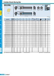
RNINGBoring Bar Cartridges Auto toolsB122B123B125B126B128B131B132B134B140B141Boring Bar Code System(ISO)Index for Boring BarInstruction of Boring BarDouble clamp systemLever Lock SystemClamp on SystemMulti Lock SystemScrew on SystemCompact MiniCarbide Shank Boring BarB146B147B148B150Cartridge Code System(ISO)Index for CartridgeClamp on SystemScrew on SystemB152B153B154B156B158Technical InformationApplication Example / IndexISO TypeMulti functional TypeMGT TypeMSB toolsB159B161B165MSB Code System(ISO)MSB ToolMSB toolsSleeve
BTurning Chip BreakersApplications range of chip breakersNegative insertsWorkpieceSteelPWorkpieceCast ironKHeavy GH VHVTRoughingHRRoughing-MAMediumVMMediumVKGRMedium tofinishingVQVCVBMedium to finishingB25FinishingVGVFVLFinishingVMWorkpieceMStainless steelWorkpieceNAluminum alloyRoughingVMRoughingMediumHSVP3MediumMedium to finishingVP2Medium to finishingHAFinishingFinishingTurning Chip BreakersWorkpieceSHeat resistant alloyRoughingVMMediumVP3TurningMedium to finishingFinishingVP2VP1B2
Turning Chip BreakersBApplications range of chip breakersPositive insertsWorkpieceSteelPWorkpieceCast ironKRoughingRoughingMediumC25MediumC25Medium to finishingHMPMedium to finishingHMPFinishingVFFinishingWorkpieceMStainless steelWorkpieceNAluminum alloyRoughingRoughingMediumC25MediumARMedium to finishingHMPMedium to finishingAKFinishingVFFinishingWorkpieceSHeat resistant alloyTurning Chip BreakersRoughingMediumHMPMedium to finishingFinishingAKTurningB3
BTurning Chip BreakersRecommended chip breaker for workpieceMaterials : 1010, 1015, 1025, 8615, 5120, 4130Hardness : under 180HBWorkpiecePSteelDepth ofcut(inch)C/BCutting edgeFeed(ipr)GradesCuttingSpeed(sfm)Insert shapeTurning Chip BreakersNegative0.004 ~0.020~ 0.059finishing0.008 ~0.031~ 0.059finishing0.020 ~0.039~ 0.059finishing0.020 ~0.039~ 0.079finishing0.020 ~0.059~ 0.138medium tofinishing0.031 ~0.059~ 0.138medium tofinishing0.039 ~0.098~ 0.197mediummachining0.098 ~0.157~ 0.276roughingHUVLVFVBVCHAVMHR0.236 ~ VH0.394~ 0.591Heavy(General)0.276 ~ VT0.472~ 0.669Heavy(High feedcutting)The first recommended cutting condition0.001 ~0.004~ 0.0100.004 ~0.008~ 0.0140.002 ~0.006~ 0.0140.006 ~0.008~ 0.0160.005 ~0.010~ 0.0180.004 ~0.008~ 0.0160.004 ~0.010~ 0.0200.010 ~0.018~ 0.0260.028 ~0.039~ 0.0550.030 ~0.047~ 0.063CN1000CN2000NC3010NC3220CN1000CN2000NC3010NC3120NC3220NC5330NC3010NC3220NC3010NC3220NC3120CN5330NC3010NC3120NC3220NC9025NC3010NC3120NC3220NC3030NC5330CN2000NC3010NC3120NC3220NC303092489199099089185810238911023759990825957825825660990759759594891759759693660726495429429330NC3010 165~825NC3030 165~495NC500H 165~495NC5330 165~495NC3010 165~825NC3030 165~495NC500H 165~495NC5330 165~495CNG(M)Gp. B18CNMGDNG(M)GSNG(M)GTNG(M)Gp. B23, B24 p. B28, B31 p. B35DNMG SNMG TNMGp. B20 p. B25 p. B31p. B38p. B43p. B46CNMG DNMG SNMG TNMG VNMG WNMGp. B20 p. B25 p. B32p. B39p. B43p. B47CNMG DNMG TNMGWNMGp. B20 p. B25 p. B38p. B46CNMG DNMG SNMG TNMG VNMG WNMGp. B20 p. B25 p. B31 p. B38 p. B43 p. B47CNMG DNMG SNMG TNMG VNMG WNMGp. B19 p. B24 p. B30p. B37p. B42p. B45CNMG DNMG SNMG TNMG VNMG WNMGp. B21 p. B25 p. B32p. B39p. B44p. B47CNMG DNMG SNMG TNMGWNMGp. B19CNMMCNMMp. B22p. B33p. B24 p. B31p. B38SNMMSNMMp. B33p. B33VNMGWNMGp. B46TurningB4
Turning Chip BreakersBRecommended chip breaker for workpieceMaterials : 1010, 1015, 1025, 8615, 5120, 4130Hardness : under 180HBWorkpiecePSteelDepth ofcut(inch)C/BCutting edgeFeed(ipr)GradesCuttingSpeed(sfm)Insert shapePositive0.004 ~0.020~ 0.059finishingVF0.020 ~0.006~ 0.010NC3010NC3120NC3220NC5330CC105CN1000CN2000924825825825858792759CCMT DCMT SCMT TCMT VCMTp. B50 p. B53 p. B55p. B59p. B450.004 ~0.020~ 0.039finishingVL0.002 ~0.004~ 0.008NC3010NC3220NC3120CN5330957825825660TC(P)MTp. B59VC(B)MTp. B650.020 ~0.059~ 0.138medium tofinishingHMP0.003 ~0.008~ 0.016NC3010NC3120NC3220NC5330CN1000CN2000858759759660792759CCMT DCMT SCMT TCMT VCMTp. B50 p. B53 p. B55p. B59p. B650.039 ~0.079~ 0.118mediummachiningC250.004 ~0.010~ 0.014NC3010NC3120NC3220NC5330CN1000CN2000825726726660792759CCMT DCMT SCMT TCMTp. B50 p. B54 p. B55p. B59The first recommended cutting conditionTurning Chip BreakersTurningB5
BTurning Chip BreakersRecommended chip breaker for workpieceMaterials : 1045, 1049, 4140, 1522Hardness : under 180~260HBWorkpiecePSteelDepth ofcut(inch)C/BCutting edgeFeed(ipr)GradesCuttingSpeed(sfm)Insert shapeTurning Chip BreakersTurningNegativePositive0.020 ~0.039~ 0.059finishing0.020 ~0.039~ 0.079finishing0.020 ~0.059~ 0.138Medium tofinishing0.039 ~0.098~ 0.197mediummachining0.098 ~0.157~ 0.276roughing0.004 ~0.020~ 0.039FinishingVFVBVCVMHR0.236 ~ VH0.394~ 0.591Heavy(General)0.276 ~ VT0.472~ 0.669Heavy(High feedcutting)VF0.004 ~0.020~ 0.059finishingVL0.020 ~HFP0.059~ 0.138finishingC250.039 ~0.079~ 0.118mediummachiningThe first recommended cutting condition0.002 ~0.006~ 0.0140.006 ~0.008~ 0.0160.005 ~0.010~ 0.0180.004 ~0.010~ 0.0020.010 ~0.018~ 0.0260.028 ~0.039~ 0.0550.030 ~0.047~ 0.0630.002 ~0.006~ 0.0100.002 ~0.004~ 0.0080.003 ~0.008~ 0.0160.004 ~0.010~ 0.014NC3010NC3220NC3120NC3010NC3220NC3010NC3220NC3120CN5330NC3010NC3120NC3220NC3030CN2000NC3010NC3120NC3220NC3030NC3010NC3220NC3120CN5330726660627990825957825825660660561594495561561495495429NC3010 165~825NC3030 165~495NC500H 165~495NC5330 165~495NC3010 165~825NC3030 165~495NC500H 165~495NC5330 165~495NC3010NC3120NC3220NC5330CC105CN1000CN2000NC3010NC3120NC3220NC5330CC105CN1000NC3010NC3120NC3220NC3030CN1000CN2000924825825825858891858957825825660726627627594858660660561594495561528CNMGp. B20 p. B25 p. B32p. B39p. B43p. B47CNMG DNMGTNMGWNMGp. B20 p. B25 p. B38p. B46CNMG DNMG SNMG TNMG VNMG WNMGp. B19CNMMp. B22CNMMDNMGSNMGp. B31SNMMp. B33SNMMTNMGp. B59TC(P)MTVNMGp. B65VC(B)MTWNMGp. B20 p. B25 p. B31 p. B38 p. B43 p. B47CNMG DNMG SNMG TNMG VNMG WNMGp. B21CNMGp. B22p. B25DNMGp. B32SNMGp. B39TNMGCCMT DCMT SCMT TCMT VCMTp. B50p. B59p. B65CCG(M)T DCG(M)T SCG(M)T TCG(M)T VCG(M)Tp. B50p. B53p. B55p. B59CCMT DCMT SCMT TCMTp. B50p. B24p. B53p. B54p. B33p. B55p. B55p. B38p. B59p. B44p. B65p. B47WNMGp. B46B6
Turning Chip BreakersBRecommended chip breaker for workpieceMaterials : 4320, 4340, 5140, F2, D3, 4140, Hardened steelHardness : 260~350HBWorkpiecePSteelDepth ofcut(inch)C/BCutting edgeFeed(ipr)GradesCuttingSpeed(sfm)Insert shapeNegativePositive0.020 ~0.039~ 0.059finishing0.020 ~0.039~ 0.079finishing0.004 ~0.020~ 0.039FinishingVFVB0.020 ~ VC0.059~ 0.138Medium tofinishing0.039 ~ VM0.098~ 0.197medium toroughing0.098 ~HR0.157~ 0.276roughing0.236 ~ VH0.394~ 0.591Heavy(General)0.276 ~ VT0.472~ 0.669Heavy(High feedcutting)VF0.004 ~0.020~ 0.059finishingVL0.020 ~HFP0.059~ 0.138finishingC250.039 ~0.079~ 0.118mediummachiningThe first recommended cutting condition0.003 ~0.006~ 0.0120.006 ~0.008~ 0.0160.005 ~0.010~ 0.0180.004 ~0.010~ 0.0020.010 ~0.014~ 0.0240.028 ~0.039~ 0.0550.030 ~0.047~ 0.0630.002 ~0.006~ 0.0100.002 ~0.004~ 0.0080.003 ~0.008~ 0.0160.004 ~0.010~ 0.014NC3010NC3220NC3120NC3010NC3020NC3220NC3010NC3220NC3120CN5330NC3010NC3120NC3220CN2000NC3010NC3120NC3220NC3030NC3010NC3030NC500HNC5330NC3010NC3030NC500HNC5330NC3010NC3120NC3220NC5330CC105CN1000CN2000NC3010NC3220NC3120CN5330NC3010NC3120NC3220CC105NC3010NC3120NC3220NC3030CN1000CN2000429363363990825825957825825660429330363297330297297264165~825165~495165~495165~495165~825165~495165~495165~495924825825825858825792957825825660429363396396363330330297330297CNMGp. B20 p. B25 p. B32p. B39p. B43p. B47CNMG DNMGTNMGWNMGp. B20 p. B25 p. B38p. B46CNMG DNMG SNMG TNMG VNMG WNMGp. B19CNMMCNMMDNMGSNMGp. B31SNMMSNMMTNMGp. B59TC(P)MTp. B59 B39VNMGp. B65VC(B)MTp. B65 B43WNMGp. B20 p. B25 p. B31 p. B38 p. B43 p. B47CNMG DNMG SNMG TNMG VNMG WNMGp. B21CNMGp. B22p. B22p. B25DNMGSNMGTNMGCCMT DCMT SCMT TCMT VCMTp. B50CCG(M)T DCG(M)T SCG(M)T TCG(M)T VCG(M)Tp. B50CCMT DCMT SCMT TCMTp. B50p. B24p. B53p. B53p. B54p. B32p. B33p. B33p. B55p. B55p. B55p. B39p. B38p. B59p. B59p. B44p. B65p. B47WNMGp. B46Turning Chip BreakersTurningB7
BTurning Chip BreakersRecommended chip breaker for workpieceMaterials : 304, 316, 430, 630Ferrite, austenite, martensite, precipitation hardening stainless steelsHardness : 135~300HBWorkpieceMStainless steelDepth ofcut(inch)C/BCutting edgeFeed(ipr)GradesCuttingSpeed(sfm)Insert shapeNegative0.039~0.098~ 0.157mediummachining0.079 ~0.177~ 0.256roughing0.020 ~0.059~ 0.157Medium tofinishing0.039 ~0.079~ 0.177MediumHSVMVP2VP30.004 ~0.010~ 0.0160.008 ~0.016~ 0.0240.001 ~0.006~ 0.0120.004 ~0.010~ 0.016PC8110NC9025PC5300PC9030PC8110NC5330PC5300PC9030PC8110NC9025PC5300PC9030PC8110NC9025PC5300PC9030924660528396825594495396825594495396924660528396CNMGp. B20 p. B24 p. B31p. B38p. B42p. B46CNMG DNMG SNMG TNMG VNMG WNMGp. B21 p. B25 p. B32p. B39p. B44p. B47CNMG DNMG SNMG TNMGWNMGp. B21CNMGp. B21DNMGp. B26DNMGp. B26SNMGp. B32SNMGp. B32TNMGp. B39TNMGp. B39VNMGVNMGp. B43WNMGp. B48WNMGp. B48Positive0.004 ~0.020~ 0.059finishing0.020 ~0.059~ 0.118medium tofinishing0.039 ~0.079~ 0.118mediummachiningVFHMPC25The first recommended cutting condition0.002 ~0.006~ 0.0100.004 ~0.008~ 0.0120.004 ~0.010~ 0.014NC3010NC3120NC3220NC5330CC105CN1000CN2000PC8110NC9025PC5300PC9030CN1000CN2000PC8110NC9025PC5300PC9030CN1000CN2000924825825825858891858825660594495858792825660561462495429CCMT DCMT SCMT TCMT VCMTp. B50p. B53p. B55p. B59p. B65CCMT DCMT SCMT TCMT VCMTp. B50p. B53p. B55p. B59CCMT DCMT SCMT TCMTp. B50 p. B54 p. B55p. B59p. B65TurningTurning Chip BreakersB8
Turning Chip BreakersBRecommended chip breaker for workpieceMaterials : No208B, No55B, 60-40-18, 80-55-06, etc : Gray cast iron, Ductile cast ironHardness : 135 ~185HBTensile strength : 450N/mm 2WorkpieceKCast ironDepth ofcut(inch)C/BCutting edgeFeed(ipr)GradesCuttingSpeed(sfm)Insert shapeNegative0.039 ~0.098~ 0.236roughing0.020 ~0.079~ 0.138medium tofinishing0.039 ~0.098~ 0.157mediummachining0.039 ~0.118~ 0.177medium toroughing0.039 ~0.098~ 0.197medium toroughing0.169 ~0.256~ 0.394heavyroughingC/B NoneB25VMGRVKGH0.002 ~0.004~ 0.0240.008 ~0.014~ 0.0240.006 ~0.012~ 0.0200.008 ~0.014~ 0.0200.006 ~0.010~ 0.0200.012 ~0.028~ 0.043KB410KB350KB370NC6205NC6210NC315KNC6205NC6210NC315KNC6205NC6210NC315KNC6205NC6210NC315KNC6205NC6210NC315KNC6210NC315K495 ~ 660660 ~ 16501650 ~ 6600825 ~ 1485660 ~ 1155495 ~ 9901320~1485990~1320495~8251485~18151155~1485660~8251485~18151155~1485660~8251485~18151155~1485660~825594495CNMA DNMA SNMA TNMAp. B18p. B23p. B29p. B36CNMG DNMG SNMG TNMG VNMGCNMGp. B18DNMGp. B23SNMGp. B29p. B19 p. B23 p. B30CNMG DNMG SNMGp. B36p. B21 p. B25 p. B32p. B39p. B44p. B47CNMG DNMG SNMG TNMGWNMGp. B37TNMGp. B45p. B45WNMGp. B22 p. B26 p. B33p. B40p. B44p. B48CNMMSNMMp. B22 p. B33TNMGVNMGVNMGWNMGPositive0.020 ~0.059~ 0.138medium tofinishing0.039 ~0.079~ 0.138mediummachiningHMPC25The first recommended cutting condition0.003 ~0.008~ 0.0160.004 ~0.010~ 0.016NC6205NC6210NC315KNC6205NC6210NC315K825795660825795660CCMT DCMT SCMT TCMT VCMTp. B50 p. B53 p. B55p. B59CCMT DCMT SCMT TCMTp. B50 p. B54 p. B55p. B59p. B65Turning Chip BreakersTurningB9
BTurning Chip BreakersRecommended chip breaker for workpieceMaterials : Aluminum alloyHardness : 20~110HBWorkpieceNAluminum alloyDepth ofcut(inch)C/BCutting edgeFeed(ipr)GradesCuttingSpeed(sfm)Insert shapeNegative0.020 ~0.079~ 0.236mediummachiningHA0.004 ~0.008~ 0.020H011650CNMG DNMG SNMG TNMG VNMG WNMGp. B19 p. B24 p. B30 p. B37 p. B42 p. B45Turning Chip BreakersTurningNegative Positive0.004 ~0.039~ 0.157mediumtofinishing0.020 ~0.059~ 0.157mediummachiningMaterials : Copper Bronze alloyHardness : 20~110HBCCGTCCGTCCGTDCGTDCGTRecommended chip breaker for workpiece0.020 ~0.079~ 0.157mediummachinin0.004 ~0.039~ 0.118mediumtofinishing0.020 ~0.059~ 0.118mediummachininAKARThe first recommended cutting conditionPositiveDepth ofcut(inch)HAAKARC/BCutting edgeThe first recommended cutting condition0.001 ~0.008~ 0.0160.002 ~0.012~ 0.020Feed(ipr)0.004 ~0.008~ 0.0200.001 ~0.008~ 0.0120.002 ~0.010~0.016H01ND1000PD1000H01ND1000PD1000GradesPC130PC230H01PC130PC230H01PC130PC230H01330033003300330033003300CuttingSpeed(sfm)165016503300165016503300165016503300CNMGDCGTSCGTSCGTSCGTTCGTTCGTTCGTVCGTVCGTVCGTRCGTp. B68 p. B69 p. B71p. B72p. B73p. B70RCGTp. B68 p. B69 p. B71p. B72p. B73p. B70DNMGSNMGInsert shapeTNMGVNMGWorkpiecep. B19 p. B24 p. B30 p. B37 p. B42 p. B45RCGTp. B68 p. B69 p. B71p. B72p. B73p. B70CCGT DCGT SCGT TCGT VCGT RCGTp. B68 p. B69 p. B71p. B72p. B73p. B70NAluminum alloyWNMGB10
Turning Chip BreakersBRecommended chip breaker for workpieceMaterials : Inconel, Nimonic, Stellite, Ti alloyHardness : 160~350HBWorkpieceSHeat resistantalloyDepth ofcut(inch)C/BCutting edgeFeed(ipr)GradesCuttingSpeed(sfm)Insert shapeNegative0.059 ~0.118~ 0.217medium toroughing0.079 ~0.177~ 0.236medium toroughing0.004 ~0.020~ 0.059Finishing0.020 ~0.059~ 0.157Medium tofinishing0.039 ~0.079~ 0.177MediumGSVMVP1VP2VP30.006 ~0.012~ 0.0200.008 ~0.016~ 0.0240.002 ~0.004~ 0.0080.004 ~0.008~ 0.0160.005 ~0.008~ 0.018PC8110NC9025PC5300PC8110NC5330PC5300PC8110PC5300NC5330PC8110PC5300NC5330PC8110PC5300NC53302641659926416599198165165198165165198165165CNMGDNMGp. B19 p. B24 p. B30p. B37p. B45CNMG DNMG SNMG TNMG VNMG WNMGp. B21 p. B25 p. B32p. B39p. B44p. B47CNMG DNMGp. B21 p. B26CNMG DNMGp. B21CNMGp. B21p. B26DNMGp. B26SNMGSNMGp. B32SNMGp. B32TNMGTNMGp. B39TNMGp. B39VNMGp. B43WNMGWNMGp. B48WNMGp. B48Positive0.004 ~0.020~ 0.059finishing0.020 ~0.059~ 0.118medium tofinishing0.039 ~0.059~ 0.118mediummachiningHFPHMPC25The first recommended cutting condition0.002 ~0.006~ 0.0100.004 ~0.008~ 0.0120.006 ~0.010~ 0.014PC8110NC9025PC5300PC8110NC9025PC5300PC9030PC8110NC9025PC5300264165992641651989926416599CCG(M)T DCG(M)T SCG(M)T TCG(M)T VCG(M)Tp. B50CCMT DCMT SCMT TCMT VCMTp. B50p. B53p. B53p. B55p. B55CCMT DCMT SCMT TCMTp. B59p. B59p. B50 p. B54 p. B55p. B59p. B65p. B65Turning Chip BreakersTurningB11
BTurning Chip BreakersNew Chip BreakersVH / VT Chip BreakerHeavy duty chip breaker suitable for Heavy machining in the ship building and power plant industries(Heavy duty machining)Suitable for large horizontal machines when machining shafts, rollers, rotors and optimal for the big flange machiningSpecial features of VH• For good chip control in heavy machining (comprehensive type)Designed from the study of heavy cuttingmechanismSmooth chip control from the high rake angle Wider cutting edge land provides strongercuttingApplications range of Chip breakersSpecial features of VTUnique cutting edge treatment providessmooth cuttingOptimized chip pocket design providessmooth chip flow• For long tool life and stable cutting (higher feeds, big depth)in heavy machiningDesigned from the study of heavy cuttingmechanismStrong edge design provides long and stable cutting(2 step rake angle of cutting edge)Varied cutting edge land strengthens thecutting edgeThe positioning of the chip breakingconvex dot deflects the machining heat,optimizes inserts wear & absorb shockGH : ap=0.20~0.47inch fn=0.021~0.047iprVH : ap=0.24~0.59inch fn=0.027~0.055iprVT : ap=0.28~0.67inch fn=0.030~0.063iprTurning Chip BreakersTurningB12LW / VW Chip BreakerImproved productivity with higher feed rates and surface finishesImproved wear resistance and toughnessSpecial features of LWSpecial features of VWCurvilinear cutting edge- Reduces cutting forceCutting edge design able to handle deeper depth of cuts- lower cutting load & reduces heatGreater chip control at shallow depths of cuts- Chip pocket design improves smooth chip flowFor shallow depth cutting and low speed machining- 3D design at the cornerExcellent Finishing applications- Excellent chip controlInsert design great for stable clmaping- Chip breaker designed close to the cutting edgeSimilar cutting edge to C/B for medium- strong cutting edge3 Dimensional dot design on cutting corner- reduces cutting force and good chip control atshallow depth of cut(Wiper)Wiper InsertHigh productivityImproved surface roughnessHigh feed-reducing machining timeImproved tool life due to reducecutting force
Turning Chip BreakersBNew Chip BreakersVL Chip Breaker(Mild steel)Improved chip control for machining material that have high toughness such as low carbonsteel, pipe, steel plate etcImproved chip control and decreased cutting load on external, facing, and copying applicationsImproved strength of the cutting edge for measurable efficiency in automated productionSpecial features of VL2 steps designed chip-breaker - Suitable Mild steel- Stable chip control on the low feed and cutting depthDesigned with special dots - Stable chip breaking on the low cutting depthApplied side rake angle - Improved chip control on facing, copying applications- Decreased cutting load and better surface finishChip control testVL Chip Breakers Comp. A Comp. B Comp. C• Workpiece : AISI1020• Cutting Condition : vc=830sfmfn=0.008ipr(Side)ap=0.02inchwet• Designation : DNMG432-VLFEM Cutting simulation analysis in the designFor design of geometry, chip shapesand chip flow are predictableOptimal chip breaker design byvarious cutting conditions andworkpieceslow temperature(℃) highVB Chip Breaker Excellent chip evacuation in continuous and high speed machining of various workpieces. Longer tool life due to 3 dimensional chip breaker realizing low cutting resistance and high rigidity of the cutting edge. Stable chip control in copying and internal machining.Special features of VB6 bumps on the insert cornerSuperior chip control and chipcutting in copying with variousdepths of cutPerformance(Copying)Side rake angleSuperb chip cutting in facing and copyingSuperior tool life due to improved surfaceroughness and lower cutting resistanceCutting edge on 100˚ part formedium machining (For CNMG)Excellent chip evacuation andtoughness in machining with highdepth of cutTurning Chip BreakersBettermachingBetterChip controlLongertool lifeTurningVB Chip BreakersConventional chip breakerB13
BTurning Chip BreakersNew Chip BreakersVC Chip Breaker(For medium-finishing)Superior chip evacuation in high speed and continuous machining of various workpieces(carbon steel, alloy steel etc.)Korloy 3 dimensional chip breaker ensures longer tool life due to low cutting load andimproved cutting edge strength.Stable chip control in copying and internal machiningSpecial features of VC4 bums on the insert cornerExcellent chip control in various depths of cut and superb chip cutting in external, internal,copy machining and facing.Superior chip control in copy machiningVC Chip BreakersConventional chip breakerVP Chip BreakerVP1(for finishing)High positive cutting edge reduces chip contactMinimized temperature while machining ensures longer tool lifeStable machining with superior chip evacuation in high depths of cutHigh positive cutting edge Longer tool life due to minimizing chip contact and reducing cutting heat whilemachining. Recommended cutting condition • fn=0.002~0.008ipr • ap=0.004~0.060inchVP1VP2(for medium to finishing)Turning Chip BreakersHigh positive cutting edge and side rake angle Improved machining performance with stable chip control in ball machining withvarious depth of cuts. Recommended cutting condition • fn=0.004~0.016ipr • ap=0.020~0.177inchVP3(for medium machining)High positive cutting edge and wide land Stable machinability in interrupted machining toughness.Stable chip evacuation and machining in machining with high depth of cut. Recommended cutting condition • fn=0.004~0.018ipr • ap=0.020~0.200inchWorkpiece SVP2VP3Titanium Alloy Ni, Co-Based AlloyTurningB14Machining of Hard-to-cut material(Difficulty factors of Hard-to-cut material) Rapid wear on the cutting edge. Frequent fracture and chipping on the cutting edge. High cutting resistance. Rapidly rising temperature on the cutting edge. Increased built-up-edge due to bad chip control.Line-up for chip breakers for hard-to-cutmaterial machining
BTurningB
BTurning Insert Code System (ISO)T N M G 31 2 3 4 5Insert Shape Relief Angle Tolerance Cross Section TypeCutting Edge Length,Diameter of Inscribed Circle1Insert ShapeRelief AngleT N M G 3 3 2 - VM 2 TNMG 3 3 2 - VMCD E K LBCDESpecial typeR S T V WFNPO3ToleranceT N M G 3 3 2 - VM4Cross Section TypeTNMG 3 3 2 - VMd : Inscribed circlet : Thicknessm : Refer to figureC’Sink 70° ~ 90° C’Sink 70° ~ 90°Turning Insert Code System (ISO)TurningB16(inch)Class d m tA±0.0010±0.0002±0.0010C±0.0010±0.0005±0.0010H±0.0005±0.0005±0.0010E±0.0010±0.0010±0.0010G±0.0010±0.0010±0.0005J * ±0.002 ~ ±0.006±0.0002±0.0010K * ±0.002 ~ ±0.006±0.0005±0.0010L * ±0.002 ~ ±0.006±0.0010±0.0010M * ±0.002 ~ ±0.006 ±0.003 ~ ±0.008 ±0.0005N * ±0.002 ~ ±0.006 ±0.003 ~ ±0.007 ±0.0010U * ±0.003 ~ ±0.010 ±0.005 ~ ±0.015 ±0.0005* Sides are based on unground insertTolerance on C,E,H,M,O,P,R,S,T,W Insert Shape (Exceptional case)dTolerance on dTolerance on mJ, K, L, M, N UM, NU6.35±0.002 ±0.003 ±0.003 ±0.0059.525±0.002 ±0.003 ±0.003 ±0.00512.7±0.003 ±0.005 ±0.005 ±0.00815.875 ±0.004 ±0.007 ±0.06 ±0.01119.05±0.004 ±0.007 ±0.06 ±0.01125.4±0.005 ±0.01±0.07 ±0.015Tolerance on D Insert Shape (Exceptional case)dTolerance on d6.35±0.0029.525±0.00212.7±0.00315.875±0.00419.05±0.004Tolerance on m±0.0043±0.0043±0.006±0.007±0.007A B CC’Sink 70° ~ 90°F G HC’Sink 70° ~ 90°J M NC’Sink 40° ~ 60°C’Sink 40° ~ 60°Q R TSpecial typeC’Sink 40° ~ 60° C’Sink 40° ~ 60°U W X
Turning Insert Code System (ISO)B3 2 - VM6 7 8Height of Cutting Edge Nose Radius (Nose R) Chip Breaker for Turning5Cutting Edge Length, Diameter of Inscribed CircleT N M G 3 3 2 - VM6Height of Cutting EdgeT N M G 3 3 2 - VMSymbolInchIC030405-0608-09-11-121416-1719-22-2532-7040506-0709-11-13-151719-2123-27-3138-030405-0607-09-11-121415-1719-22-2531-Metric060809-1113-16-19-222427-3033-38-4454-0304050606070809101112121415161719202225253132Nose Radius (Nose R)-0809-1113-16-19-222427-3033-38-4454-02S303-0405-06-07-080910-1113-15-1721-1.2(5)1.5(6)1.8(7)-22.5-3-3.5-44.55-5.56-7-810-d(inch)5/323/167/320.2361/45/160.3153/80.3947/160.4721/29/165/80.63011/163/40.7877/80.984111/41.260( ) Symbol for small size insertT N M G 3 3 2 - VM8Metric01T0T102T203T304050607091112VGSymbolInch1(2)1.1251.21.5(3)1.7522.533.545678Height of Cutting Edge(t)mmInch1.591/161.799/1281.985/642.383/322.787/643.181/83.975/324.763/165.567/326.351/47.945/169.523/811.117/1612.701/2( ) Symbol for small size insertChip Breaker for TurningT N M G 3 3 2 - VMVLVFVBVCVQTurning Insert Code System (ISO)SymbolCorner RadiusMetric Inch Metric Inch0102040812162024283200.5123456780.10.20.40.81.21.62.02.42.83.20.0040.0081/641/323/641/165/643/327/641/800M0--Round insert(Inch)Round insert(Metric)VWVM VH VT VK VP1VP2 VP3 HA HS HR GSGMC25GRAKGHARB25VFHMPTurningB17
BTurning Insert (Negative)CNRhombic80° NegativeWorkpieceSteelStainless steelCast ironNon-ferrous metalHeat resistant alloy, Titanium alloyHardened steelPMKNSHMachining typesContinuous cuttingGeneral cuttingInterrupted cuttingCoated Cermet Coated Uncoated Dimensions (inch) Cutting ConditionAvailable tool holdersInsertsDesignationNC3010NC3120NC3220NC3030NC500HNC9020NC5330PC8110PC5300PC9030NC6205NC6210NC315KCN1000CN2000CN20CC105CC115U20H01G10Id t rd1fn(ipr)ap(inch)DesignationPageCNGG-HUFinishing431-HU432-HU0.4880.4721/21/23/163/161/641/3213/6413/640.001~0.0100.001~0.0100.004~0.0590.004~0.059MCKNR/LMCLNR/LMCMNNMCRNR/LPCBNR/LPCLNR/LB106B106B106B107B94B95CNGG-VP1Finishing430.5-VP1431-VP1432-VP10.4960.4880.4721/21/21/23/163/163/161/1281/641/3213/6413/6413/640.004~0.0390.004~0.0590.004~0.0590.000~0.0040.002~0.0060.003~0.008MCKNR/LMCLNR/LMCMNNMCRNR/LPCBNR/LPCLNR/LB106B106B106B107B94B95Turning Insert (Negative)TurningRoughingMedium RoughingMediumCNMACNMG-B25CNMG-GM322431432433434542543544642643644431-B25432-B25433-B25542-B25543-B25544-B25641-B25642-B25643-B25644-B25321-GM322-GM431-GM432-GM433-GM642-GM 0.3460.4880.4720.4570.4410.6020.5830.5670.7280.7130.6970.4880.4720.4570.6020.5830.5670.7440.7280.7130.6970.3620.3460.4880.4720.4570.7283/81/21/21/21/25/85/85/83/43/43/41/21/21/25/85/85/83/43/43/43/43/83/81/21/21/23/41/83/163/163/163/161/41/41/41/41/41/43/163/163/161/41/41/41/41/41/41/41/81/83/163/163/161/41/321/641/323/641/161/323/641/161/323/641/161/641/323/641/323/611/161/641/323/641/161/641/321/641/323/641/321/813/6413/6413/6413/641/41/41/45/165/165/1613/6413/6413/641/41/41/45/165/165/165/165/325/3213/6413/6413/645/160.004~0.0120.006~0.0240.006~0.0250.006~0.0280.008~0.0390.006~0.0310.006~0.0310.008~0.0390.006~0.0240.008~0.0310.008~0.0390.007~0.0180.009~0.0240.010~0.0240.010~0.0240.011~0.0240.011~0.0240.008~0.0180.010~0.0240.012~0.0240.009~0.0280.002~0.0120.004~0.0180.002~0.0120.004`0.0200.007~0.0240.004~0.0200.020~0.1180.008~0.1970.008~0.3150.012~0.3150.012~0.3940.012~0.3940.012~0.3940.012~0.3940.008~0.4720.008~0.4720.008~0.4720.039~0.1970.059~0.1970.079~0.1970.079~0.2560.079~0.2560.079~0.2560.118~0.3150.118~0.3150.118~0.3150.118~0.3150.035~0.1380.039~0.1380.035~0.1970.039~0.1970.012~0.1970.039~0.315MCKNR/LMCLNR/LMCMNNMCRNR/LPCBNR/LPCLNR/LMCKNR/LMCLNR/LMCMNNMCRNR/LPCBNR/LPCLNR/LMCKNR/LMCLNR/LMCMNNMCRNR/LPCBNR/LPCLNR/LB106B106B106B107B94B95B106B106B106B107B94B95B106B106B106B107B94B95B18Cutting edge geometry A29 ~ A32 Recommended chip breakerB04 ~ B11 Code system B16 ~ B17 S.P : Special Stock item
Turning Insert (Negative)BCNRhombic80° NegativeWorkpieceSteelStainless steelCast ironNon-ferrous metalHeat resistant alloy, Titanium alloyHardened steelPMKNSHMachining typesContinuous cuttingGeneral cuttingInterrupted cuttingCoated Cermet Coated Uncoated Dimensions (inch) Cutting ConditionAvailable tool holdersInsertsDesignationNC3010NC3120NC3220NC3030NC500HNC9020NC9025NC5330PC8110PC5300PC9030NC6205NC6210NC315KCN1000CN2000CN20CC105CC115U20H01G10Idtrd1fn(ipr)ap(inch)DesignationPageCNMG-GRRoughingCNMG-GSMedium RoughingCNMG-HAMedium to finishingCNMG-HCMedium to finishing432-GR433-GR434-GR542-GR543-GR544-GR642-GR643-GR644-GR646-GR856-GR866-GR431-GS432-GS433-GS542-GS543-GS643-GS644-GS431-HA432-HA433-HA431-HC432-HC433-HC0.4720.4570.4410.6020.5830.5670.7280.7130.6970.6610.9170.9170.4880.4720.4570.6020.5830.7130.6970.4880.4720.4570.4880.4720.4571/21/21/25/85/85/83/43/43/43/4111/21/21/25/85/83/43/41/21/21/21/21/21/23/163/163/161/41/41/41/41/41/41/45/163/83/163/163/161/41/41/41/43/163/163/163/163/163/161/323/641/161/323/641/161/323/641/163/323/323/321/641/323/641/323/643/641/161/641/323/641/641/323/6413/6413/6413/641/41/41/45/165/165/165/1623/6423/6413/6413/6413/641/41/45/165/1613/6413/6413/6413/6413/6413/640.008~0.0200.010~0.0200.010~0.0240.008~0.0280.010~0.0280.010~0.0300.008~0.0280.012~0.0300.012~0.0310.014~0.0330.016~0.0390.016~0.0390.002~0.0100.004~0.0200.005~0.0260.004~0.0200.005~0.0260.005~0.0260.005~0.0260.002~0.0080.004~0.0160.005~0.0220.002~0.0120.003~0.0160.007~0.0200.039~0.2760.051~0.2760.071~0.2360.039~0.3150.051~0.3150.071~0.3150.067~0.3940.067~0.3940.071~0.3940.079~0.4720.091~0.5910.091~0.5910.004~0.1180.039~0.1970.039~0.1970.039~0.2560.039~0.2560.039~0.3070.039~0.3070.031~0.1380.031~0.1380.031~0.1380.031~0.1380.031~0.1570.039~0.157MCKNR/LMCLNR/LMCMNNMCRNR/LPCBNR/LPCLNR/LMCKNR/LMCLNR/LMCMNNMCRNR/LPCBNR/LPCLNR/LMCKNR/LMCLNR/LMCMNNMCRNR/LPCBNR/LPCLNR/LMCKNR/LMCLNR/LMCMNNMCRNR/LPCBNR/LPCLNR/LB106B106B106B107B94B95B106B106B106B107B94B95B106B106B106B107B94B95B106B106B106B107B94B95Turning Insert (Negative)CNMG-HRRoughing431-HR432-HR433-HR434-HR542-HR543-HR544-HR546-HR642-HR643-HR644-HR646-HR866-HR12.412.011.611.215.314.814.413.618.518.117.716.823.312.712.712.712.715.87515.87515.87515.87519.0519.0519.0519.0525.44.764.764.764.766.356.356.356.356.356.356.356.359.520.40.81.21.60.81.21.62.40.81.21.62.42.45.165.165.165.166.356.356.356.357.937.937.937.939.120.15~0.30 0.80~6.000.20~0.50 1.00~7.000.25~0.70 1.30~7.000.32~0.75 1.80~7.000.20~0.50 1.00~8.000.25~0.70 1.30~8.000.30~0.80 1.80~8.000.32~0.90 2.30~10.000.20~0.50 1.70~10.000.25~0.70 1.30~10.000.30~0.80 1.80~10.000.32~0.90 2.30~10.000.40~1.00 2.30~10.00MCKNR/LMCLNR/LMCMNNMCRNR/LPCBNR/LPCLNR/LB106B106B106B107B94B95TurningCutting edge geometry A29 ~ A32 Recommended chip breakerB04 ~ B11 Code system B16 ~ B17 S.P : Special Stock itemB19
BTurning Insert (Negative)CNRhombic80° NegativeWorkpieceSteelStainless steelCast ironNon-ferrous metalHeat resistant alloy, Titanium alloyHardened steelInsertsPMKNSHDesignationCoated Cermet Coated Uncoated Dimensions (inch) Cutting ConditionNC3010NC3120NC3220NC3030NC9020NC9025NC5330PC8110PC5300PC9030NC6205NC6210NC315KCN1000CN2000CN20CC105CC115U20H01G10IMachining typesd t rd1Continuous cuttingGeneral cuttingInterrupted cuttingfn(ipr)ap(inch)Available tool holdersDesignationPageCNMG-HSMedium cutting321-HS322-HS431-HS432-HS433-HS543-HS544-HS643-HS644-HS 0.3620.3460.4880.4720.4570.5830.5670.7130.6973/83/81/21/21/25/85/83/43/41/81/83/163/163/161/41/41/41/41/641/321/641/323/643/611/163/641/165/325/3213/6413/6413/641/41/45/165/160.002~0.0080.004~0.0080.004~0.0080.005~0.0220.005~0.0220.005~0.0220.006~0.0240.005~0.0220.006~0.0240.039~0.0980.039~0.0980.039~0.1770.039~0.1770.039~0.1770.079~0.2360.079~0.2360.079~0.2870.079~0.287MCKNR/LMCLNR/LMCMNNMCRNR/LPCBNR/LPCLNR/LB106B106B106B107B94B95CNMG-HUFinishingCNMG-LW(Wiper)Medium cutting431-HU432-HU433-HU432-LW433-LW0.4880.4720.4570.4720.4571/21/21/21/21/23/163/163/163/163/161/641/323/641/323/6413/6413/6413/6413/6413/640.002~0.0100.004~0.0140.005~0.0160.006~0.0240.008~0.0280.004~0.0390.008~0.0590.012~0.0590.040~0.2000.040~0.240MCKNR/LMCLNR/LMCMNNMCRNR/LPCBNR/LPCLNR/LMCKNR/LMCLNR/LMCMNNMCRNR/LPCBNR/LPCLNR/LB106B106B106B107B94B95B106B106B106B107B94B95Turning Insert (Negative)CNMG-VBFinishingCNMG-VC(Mild steel)Finishing431-VB432-VB433-VB431-VC432-VC433-VC0.4720.4570.4570.4880.4720.4571/21/21/21/21/21/23/163/163/163/163/163/161/323/643/641/641/323/6413/6413/6413/6413/6413/6413/640.006~0.0240.008~0.0280.008~0.0200.004~0.0140.006~0.0160.008~0.0180.040~0.2000.040~0.2400.040~0.2400.012~0.0790.020~0.1180.020~0.118MCKNR/LMCLNR/LMCMNNMCRNR/LPCBNR/LPCLNR/LMCKNR/LMCLNR/LMCMNNMCRNR/LPCBNR/LPCLNR/LB106B106B106B107B94B95B106B106B106B107B94B95CNMG-VL(Mild steel)Finishing431-VL432-VL0.4880.4721/21/23/163/161/641/3213/6413/640.002~0.0100.004~0.0140.004~0.0400.008~0.060MCKNR/LMCLNR/LMCMNNMCRNR/LPCBNR/LPCLNR/LB106B106B106B107B94B95TurningCNMG-VFFinishing321-VF322-VF431-VF432-VF433-VF0.3620.3460.4880.4720.4573/83/81/21/21/21/81/83/163/163/161/641/321/641/323/645/325/3213/6413/6413/640.003~0.0120.005~0.0060.003~0.0120.004~0.0160.004~0.0200.020~0.0590.020~0.0590.020~0.0590.020~0.0590.024~0.059MCKNR/LMCLNR/LMCMNNMCRNR/LPCBNR/LPCLNR/LB106B106B106B107B94B95B20Cutting edge geometry A29 ~ A32 Recommended chip breakerB04 ~ B11 Code system B16 ~ B17 S.P : Special Stock item
Turning Insert (Negative)BCNRhombic80° NegativeWorkpieceSteelStainless steelCast ironNon-ferrous metalHeat resistant alloy, Titanium alloyHardened steelInsertsPMKNSHDesignationCoated Cermet Coated Uncoated Dimensions (inch) Cutting ConditionNC3010NC3120NC3220NC3030NC9020NC9025NC5330PC8110PC5300PC9030NC6205NC6210NC315KCN1000CN2000CN20CC105CC115U20H01G10IMachining typesd t rd1Continuous cuttingGeneral cuttingInterrupted cuttingfn(ipr)ap(inch)Available tool holdersDesignationPageCNMG-VGFinishing321-VG322-VG431-VG432-VG0.3620.3460.4880.4723/83/81/21/21/81/83/163/161/641/321/641/325/325/3213/6413/640.003~0.0120.003~0.0120.003~0.0120.004~0.0160.020~0.0590.020~0.0590.020~0.0590.020~0.059MCKNR/LMCLNR/LMCMNNMCRNR/LPCBNR/LPCLNR/LB106B106B106B107B94B95CNMG-VMMedium321-VM322-VM431-VM432-VM433-VM434-VM542-VM543-VM 0.3620.3460.4880.4720.4570.4410.6020.5833/83/81/21/21/21/25/85/81/81/83/163/163/163/161/43/161/641/321/641/323/641/161/323/645/325/3213/6413/6413/6413/641/41/40.002~0.0120.004~0.0180.002~0.0120.004~0.0200.005~0.0240.008~0.0230.004~0.0200.005~0.0240.035~0.1380.039~0.1380.035~0.1970.039~0.1970.051~0.1970.059~0.1970.039~0.2640.051~0.264MCKNR/LMCLNR/LMCMNNMCRNR/LPCBNR/LPCLNR/LB106B106B106B107B94B95CNMG-VP1Finishing430.5-VP1431-VP1432VP10.4960.4880.4721/21/21/23/163/163/161/1281/641/3213/6413/6413/640.004~0.0390.004~0.0590.004~0.0590.000~0.0040.002~0.0060.003~0.008MCKNR/LMCLNR/LMCMNNMCRNR/LPCBNR/LPCLNR/LB106B106B106B107B94B95CNMG-VP2Mediumto finishingCNMG-VP3Medium431-VP2432-VP2431-VP3432-VP3433-VP30.4880.4720.4880.4720.4571/21/21/21/21/23/163/163/163/163/161/641/321/641/323/6413/6413/6413/6413/6413/640.002~0.0120.004~0.0160.002~0.0120.004~0.0160.005~0.0200.004~0.1180.020~0.1770.004~0.1180.020~0.1770.020~0.197MCKNR/LMCLNR/LMCMNNMCRNR/LPCBNR/LPCLNR/LMCKNR/LMCLNR/LMCMNNMCRNR/LPCBNR/LPCLNR/LB106B106B106B107B94B95B106B106B106B107B94B95Turning Insert (Negative)CNMG-VQMedium to finishing321-VQ322-VQ431-VQ432-VQ0.3620.3460.4880.4723/83/81/21/21/81/83/163/161/641/321/641/323/203/2013/6413/640.002~0.0120.003~0.0120.002~0.0120.003~0.0160.002~0.1380.003~0.1570.031~0.1570.031~0.157MCKNR/LMCLNR/LMCMNNMCRNR/LPCBNR/LPCLNR/LB106B106B106B107B94B95CNMG-VW(Wiper) Finishing431-VW432-VW0.4880.4721/21/23/163/161/641/3213/6413/640.004~0.0120.006~0.0200.020~0.1180.020~0.157MCKNR/LMCLNR/LMCMNNMCRNR/LPCBNR/LPCLNR/LB106B106B106B107B94B95TurningCutting edge geometry A29 ~ A32 Recommended chip breakerB04 ~ B11 Code system B16 ~ B17 S.P : Special Stock itemB21
BTurning Insert (Negative)CNRhombic80° NegativeWorkpieceSteelStainless steelCast ironNon-ferrous metalHeat resistant alloy, Titanium alloyHardened steelInsertsPMKNSHDesignationCoated Cermet Coated Uncoated Dimensions (inch) Cutting ConditionNC3010NC3120NC3220NC3030NC500HNC9020NC9025NC5330PC8110PC5300PC9030NC6205NC6210CN1000CN2000CN20CC105CC115U20H01G10IMachining typesd t rd1Continuous cuttingGeneral cuttingInterrupted cuttingfn(ipr)ap(inch)Available tool holdersDesignationPageTurning Insert (Negative)CNMG-VKMedium RoughingCNMM-GHHeavyCNMM-VHHeavy(General)CNMM-VTHeavy(High feed cutting)CNMM-GM432-VK433-VK434-VK432-GH433-GH533-GH536-GH543-GH544-GH546-GH642-GH643-GH644-GH646-GH854-GH856-GH866-GH8612.5-GH643-VH644-VH646-VH856-VH866-VH643-VT644-VT646-VT856-VT866-VT432-GM0.4720.4570.4410.4720.4570.5830.5350.5830.5670.5350.7280.7130.6970.6610.9500.9170.9170.8090.7130.6970.6610.9170.9170.7130.6970.6610.9170.9170.4721/21/21/21/21/25/85/85/85/85/83/43/43/43/411113/43/43/43/413/43/43/43/411/23/163/163/163/163/163/163/161/41/41/41/41/41/41/45/165/163/83/81/41/41/45/163/81/41/41/45/163/83/161/323/641/161/323/643/643/323/641/163/321/323/641/163/321/163/323/3225/1283/641/163/323/323/323/641/163/323/323/321/3213/6413/6413/6413/6413/641/41/41/41/41/45/165/165/165/1623/6423/6423/6423/645/165/165/1623/6423/645/165/165/1623/6423/640.008~0.0200.010~0.0200.010~0.0240.012~0.0240.012~0.0280.012~0.0280.012~0.0470.012~0.0350.012~0.0470.012~0.0590.012~0.0240.012~0.0280.018~0.0350.022~0.0470.020~0.0390.022~0.0470.022~0.0470.026~0.0510.020~0.0360.020~0.0440.024~0.0480.028~0.0560.028~0.0560.024~0.0400.024~0.0440.024~0.0640.030~0.0640.030~0.0640.039~0.1970.051~0.2360.071~0.2760.098~0.3150.098~0.3150.098~0.3150.098~0.3150.098~0.3150.098~0.3150.098~0.3150.098~0.3150.118~0.3150.118~0.3150.157~0.3540.177~0.3940.197~0.4720.197~0.4720.236~0.4720.200~0.4000.200~0.4000.240~0.4800.240~0.6000.240~0.6000.240~0.5200.200~0.4000.280~0.5200.280~0.6800.280~0.680MCKNR/LMCLNR/LMCMNNMCRNR/LPCBNR/LPCLNR/LMCKNR/LMCLNR/LMCMNNMCRNR/LPCBNR/LPCLNR/LPCBNR/LPCLNR/LPCBNR/LPCLNR/L13/64 0.004~0.020 0.039~0.197 PCBNR/LPCLNR/LB106B106B106B107B94B95B106B106B106B107B94B95B94B95B94B95B94B95MediumTurningCNMM-GRRoughingCNMM-HAMediumto finishing432-GR433-GR643-GR644-GR432-HA0.4720.4570.7130.6970.4721/21/23/43/41/23/163/161/41/43/161/323/643/641/161/3213/6413/645/165/160.008~0.0200.010~0.0200.012~0.0300.012~0.0310.039~0.2760.051~0.2760.067~0.3940.071~0.394PCBNR/LPCLNR/L13/64 0.004~0.016 0.031~0.138 PCBNR/LPCLNR/LB94B95B94B95B22Cutting edge geometry A29 ~ A32 Recommended chip breakerB04 ~ B11 Code system B16 ~ B17 S.P : Special Stock item
Turning23BBTurning Insert (Negative)Turning Insert (Negative)PMKNSHDN55° NegativeRhombicDNGG-HUDNGG-VP1(inch)NC3010NC3030NC3120NC3220NC9020NC9025NC315KPC8110CC115CN20CN1000CC105CN2000H01G10U20NC5330NC6210PC5300NC6205PC9030FinishingFinishing441-HU442-HU431-VP1432-VP1441-VP1442-VP1MDJNR/LMDNNNMDQNR/LMDUNR/LPDJNR/LPDNNR/LPDSNR/LPDUNR/LB107B107B108B132B96, 150B96B128B129MDJNR/LMDNNNMDQNR/LMDUNR/LPDJNR/LPDNNR/LPDSNR/LPDUNR/LB107B107B108B132B96, 150B96B128B129Id1d t r0.5940.5790.5940.5791/21/21/21/21/21/21/41/43/163/161/41/41/641/321/641/321/641/3213/6413/6413/6413/6413/6413/64DNMADNMG-B25DNMG-GMRoughingMedium RoughingMedium332431432433441442443542430.5-B25431-B25432-B25433-B25436.5-B25440.5-B25441-B25442-B25443-B25446.5-B25322-GM331-GM332-GM431-GM432-GM433-GM441-GM442-GM443-GMMDJNR/LMDNNNMDQNR/LMDUNR/LPDJNR/LPDNNR/LPDSNR/LPDUNR/LB107B107B108B132B96, 150B96B128B129MDJNR/LMDNNNMDQNR/LMDUNR/LPDJNR/LPDNNR/LPDSNR/LPDUNR/LB107B107B108B132B96, 150B96B128B129MDJNR/LMDNNNMDQNR/LMDUNR/LPDJNR/LPDNNR/LPDSNR/LPDUNR/LB107B107B108B132B96, 150B96B128B1290.4250.5940.5790.5670.5940.5790.5670.7280.5980.5940.5790.5670.5200.5980.5940.5790.5670.5200.4250.4410.4250.5940.5790.5670.5940.5790.5673/81/21/21/21/21/21/25/81/21/21/21/21/21/21/21/21/21/23/83/83/81/21/21/21/21/21/23/163/163/163/161/41/41/41/43/163/163/163/163/161/41/41/41/41/41/83/163/163/163/163/161/41/41/41/321/641/323/641/641/323/641/321/1281/641/323/6413/1281/1281/641/323/6413/1281/321/641/321/641/323/641/641/323/645/3213/6413/6413/6413/6413/6413/645/1613/6413/6413/6413/6413/6413/6413/6413/6413/6413/645/325/325/3213/6413/6413/6413/6413/6413/64DNMG-GRRoughing432-GR433-GR434-GR442-GR443-GR444-GRMDJNR/LMDNNNMDQNR/LMDUNR/LPDJNR/LPDNNR/LPDSNR/LPDUNR/LB107B107B108B132B96, 150B96B128B1290.5790.5670.5510.5790.5670.5511/21/21/21/21/21/23/163/163/161/41/41/41/323/641/161/323/641/1613/6413/6413/6413/6413/6413/640.5910.579Machining typesSteelStainless steelCast ironNon-ferrous metalHeat resistant alloy, Titanium alloyHardened steelWorkpieceContinuous cuttingGeneral cuttingInterrupted cuttingInsertsDesignationDimensionsAvailable tool holdersPageDesignationCoated Cermet Coated Uncoated Cutting Conditionfn(ipr)ap(inch)0.002~0.0100.004~0.0120.004~0.0590.008~0.0590.002~0.0060.003~0.0080.002~0.0060.003~0.0080.004~0.0590.004~0.0590.004~0.0590.004~0.0590.007~0.0180.007~0.0220.010~0.0220.010~0.0260.007~0.0220.010~0.0220.010~0.0260.012~0.0310.031~0.1180.016~0.1570.031~0.1570.059~0.1570.016~0.1570.031~0.1570.047~0.1570.098~0.5120.006~0.0160.007~0.0180.007~0.0220.010~0.0220.014~0.0260.006~0.0160.007~0.0220.007~0.0220.010~0.0220.014~0.0260.020~0.1380.039~0.1570.059~0.1570.059~0.1570.098~0.2170.020~0.1380.059~0.1570.059~0.1570.059~0.1570.098~0.2170.004~0.0200.002~0.0120.004~0.0200.002~0.0120.004~0.0200.005~0.0240.002~0.0120.004~0.0200.005~0.0240.039~0.1570.035~0.1570.039~0.1570.035~0.1970.039~0.1970.051~0.1970.035~0.1970.039~0.1970.051~0.1970.008~0.0200.010~0.0350.012~0.0300.008~0.0200.010~0.0280.008~0.0300.039~0.2760.051~0.2760.071~0.2760.039~0.2760.051~0.2760.071~0.276Cutting edge geometry A29 ~ A32 Recommended chip breakerB04 ~ B11 Code system B16 ~ B17 S.P : Special Stock item
BTurning Insert (Negative)DNRhombic55° NegativeWorkpieceSteelStainless steelCast ironNon-ferrous metalHeat resistant alloy, Titanium alloyHardened steelPMKNSHMachining typesContinuous cuttingGeneral cuttingInterrupted cuttingCoated Cermet Coated Uncoated Dimensions (inch) Cutting ConditionAvailable tool holdersInsertsDesignationNC3010NC3120NC3220NC3030NC9020NC9025NC5330PC8110PC5300PC9030NC6205NC6210NC315KCN1000CN2000CN20CC105CC115U20H01G10Id t rd1fn(ipr)ap(inch)DesignationPageDNMG-GSMedium RoughingDNMG-HAMedium to finishing431-GS432-GS433-GS441-GS442-GS443-GS431-HA432-HA441-HA442-HA0.5940.5790.5670.5940.5790.5670.5940.5790.5940.5791/21/21/21/21/21/21/21/21/21/23/163/163/161/41/41/43/163/161/41/41/641/323/641/641/323/641/641/321/641/3213/6413/6413/6413/6413/6413/6413/6413/6413/6413/640.003~0.0160.004~0.0200.002~0.0260.003~0.0160.004~0.0200.004~0.0260.002~0.0120.004~0.0160.002~0.0120.004~0.0160.039~0.1970.039~0.1970.039~0.1970.039~0.1970.039~0.1970.039~0.1970.031~0.1380.031~0.1380.031~0.1380.031~0.138MDJNR/LMDNNNMDQNR/LMDUNR/LPDJNR/LPDNNR/LPDSNR/LPDUNR/LMDJNR/LMDNNNMDQNR/LMDUNR/LPDJNR/LPDNNR/LPDSNR/LPDUNR/LB107B107B108B132B96, 150B96B128B129B107B107B108B132B96, 150B96B128B129Turning Insert (Negative)DNMG-HCMedium to finishingDNMG-HRRoughingDNMG-HSMedium431-HC432-HC433-HC441-HC442-HC443-HC432-HR433-HR434-HR442-HR443-HR444-HR543-HR331-HS332-HS431-HS432-HS433-HS441-HS442-HS443-HS0.5940.5790.5670.5940.5790.5670.5790.5670.5510.5790.5670.5510.7110.4410.4250.5940.5790.5670.5940.5790.5671/21/21/21/21/21/21/21/21/21/21/21/25/83/83/81/21/21/21/21/21/23/163/163/161/41/41/43/163/163/161/41/41/41/43/163/163/163/163/161/41/41/41/641/643/641/641/323/641/323/641/161/323/641/163/641/641/321/641/323/641/641/323/6413/6413/6413/6413/6413/6413/6413/6413/6413/6413/6413/6413/645/165/325/3213/6413/6413/6413/6413/6413/640.007~0.0080.007~0.0080.005~0.0200.002~0.0120.003~0.0160.005`0.0200.008~0.0200.010~0.0280.012~0.0300.008~0.0200.010~0.0280.008~0.0300.008~0.0300.002~0.0140.004~0.0160.002~0.0140.004~0.0160.005~0.0220.002~0.0140.004~0.0160.004~0.0220.002~0.1380.031~0.1570.035~0.1570.031~0.1570.031~0.1570.035~0.1570.039~0.2760.051~0.2760.071~0.2760.039~0.2760.051~0.2760.071~0.2760.071~0.3150.031~0.0980.039~0.0980.031~0.1570.039~0.1570.039~0.1770.031~0.1570.039~0.1770.039~0.177MDJNR/LMDNNNMDQNR/LMDUNR/LPDJNR/LPDNNR/LPDSNR/LPDUNR/LMDJNR/LMDNNNMDQNR/LMDUNR/LPDJNR/LPDNNR/LPDSNR/LPDUNR/LMDJNR/LMDNNNMDQNR/LMDUNR/LPDJNR/LPDNNR/LPDSNR/LPDUNR/LB107B107B108B132B96, 150B96B128B129B107B107B108B132B96, 150B96B128B129B107B107B108B132B96, 150B96B128B129TurningDNMG-HUFinishingDNMG-LW(Wiper) Medium431-HU432-HU433-HU441-HU442-HU443-HU432-LW433-LW442-LW443-LW0.5940.5790.5670.5940.5790.5670.5790.5670.5790.5671/21/21/21/21/21/21/21/21/21/23/163/163/161/41/41/43/163/161/41/43/641/323/641/641/323/641/323/641/323/6413/6413/6413/6413/6413/6413/6413/6413/6413/6413/640.002~0.0100.004~0.0120.006~0.0140.002~0.0100.004~0.0120.006~0.0140.006~0.0200.008~0.0240.006~0.0200.008~0.0240.004~0.0590.008~0.0590.012~0.0590.004~0.0590.008~0.0590.012~0.0590.028~0.1770.039~0.1970.028~0.1770.039~0.197MDJNR/LMDNNNMDQNR/LMDUNR/LPDJNR/LPDNNR/LPDSNR/LPDUNR/LMDJNR/LMDNNNMDQNR/LMDUNR/LPDJNR/LPDNNR/LPDSNR/LPDUNR/LB107B107B108B132B96, 150B96B128B129B107B107B108B132B96, 150B96B128B129B24Cutting edge geometry A29 ~ A32 Recommended chip breakerB04 ~ B11 Code system B16 ~ B17 S.P : Special Stock item
Turning25BBTurning Insert (Negative)Turning Insert (Negative)PMKNSHDN55° NegativeRhombicDNMG-VBDNMG-VC(inch)NC3010NC3030NC3120NC3220NC9020NC9025NC315KPC8110CC115CN20CN1000CC105CN2000H01G10U20NC5330NC6210PC5300NC6205PC9030FinishingMedium to finishing431-VB432-VB441-VB442-VB443-VB431-VC432-VC433-VC441-VC442-VC443-VCMDJNR/LMDNNNMDQNR/LMDUNR/LPDJNR/LPDNNR/LPDSNR/LPDUNR/LB107B107B108B132B96, 150B96B128B129MDJNR/LMDNNNMDQNR/LMDUNR/LPDJNR/LPDNNR/LPDSNR/LPDUNR/LB107B107B108B132B96, 150B96B128B129Id1d t r0.5940.5790.5940.5940.5670.5940.5790.5670.5940.5790.5671/21/21/21/21/21/21/21/21/21/21/23/163/161/41/41/43/163/163/161/41/41/41/641/321/641/323/641/641/323/641/641/323/6413/6413/6413/6413/6413/6413/6413/6413/6413/6413/6413/64DNMG-VLDNMG-VFDNMG-VGDNMG-VM(Mild steel) FinishingFinishingFinishingMedium332-VL431-VL432-VL433-VL441-VL442-VL443-VL330.5-VF331-VF332-VF431-VF432-VF433-VF441-VF442-VF443-VF331-VG332-VG431-VG432-VG441-VG442-VG331-VM332-VM333-VM431-VM432-VM433-VM441-VM442-VM443-VM0.4250.5940.5790.5670.5940.5790.5670.4490.4410.4250.5940.5790.5670.5940.5790.5670.4410.4250.5940.5790.5940.5790.4410.4250.4060.5940.5790.5670.5940.5790.5673/81/21/21/21/21/21/23/83/83/81/21/21/21/21/21/23/83/81/21/21/21/23/83/83/81/21/21/21/21/21/23/163/163/163/161/41/41/43/163/163/163/163/163/161/41/41/43/163/163/163/161/41/43/163/163/163/163/163/161/41/41/41/321/641/323/641/641/323/641/1281/641/321/641/323/641/641/323/641/641/321/641/321/641/321/641/323/641/641/323/641/641/323/645/3213/6413/6413/6413/6413/6413/645/325/325/3213/6413/6413/6413/6413/6413/645/325/3213/6413/6413/6413/645/325/325/3213/6413/6413/6413/6413/6413/64MDJNR/LMDNNNMDQNR/LMDUNR/LPDJNR/LPDNNR/LPDSNR/LPDUNR/LB107B107B108B132B96, 150B96B128B129MDJNR/LMDNNNMDQNR/LMDUNR/LPDJNR/LPDNNR/LPDSNR/LPDUNR/LB107B107B108B132B96, 150B96B128B129MDJNR/LMDNNNMDQNR/LMDUNR/LPDJNR/LPDNNR/LPDSNR/LPDUNR/LB107B107B108B132B96, 150B96B128B129MDJNR/LMDNNNMDQNR/LMDUNR/LPDJNR/LPDNNR/LPDSNR/LPDUNR/LB107B107B108B132B96, 150B96B128B129Machining typesSteelStainless steelCast ironNon-ferrous metalHeat resistant alloy, Titanium alloyHardened steelWorkpieceContinuous cuttingGeneral cuttingInterrupted cuttingInsertsDesignationDimensionsAvailable tool holdersPageDesignationCoated Cermet Coated Uncoated Cutting Conditionfn(ipr)ap(inch)0.004~0.0120.006~0.0180.004~0.0120.006~0.0180.008~0.0200.012~0.0800.020~0.0800.012~0.0800.020~0.0800.020~0.0980.004~0.0140.006~0.0160.006~0.0180.004~0.0140.006~0.0160.006~0.0180.012~0.0790.020~0.1180.020~0.1180.012~0.0790.020~0.1180.020~0.1180.002~0.0080.002~0.0100.002~0.0120.004~0.0120.002~0.0100.002~0.0120.004~0.0120.004~0.0400.004~0.0600.008~0.0600.010~0.0600.004~0.0600.008~0.0600.010~0.0600.002~0.0080.003~0.0120.004~0.0160.003~0.0120.004~0.0160.006~0.0200.005~0.0120.004~0.0160.006~0.0200.008~0.0390.020~0.0590.020~0.0590.020~0.0590.020~0.0590.024~0.0590.020~0.0590.020~0.0590.024~0.0590.003~0.0120.004~0.0160.003~0.0120.004~0.0160.005~0.0120.004~0.0160.020~0.0590.020~0.0590.020~0.0590.020~0.0590.020~0.0590.020~0.0590.002~0.0120.004~0.0200.005~0.0200.002~0.0120.004~0.0200.005~0.0240.002~0.0120.004~0.0200.005~0.0240.035~0.1570.039~0.1570.051~0.1570.035~0.1970.039~0.1970.051~0.1970.035~0.1970.039~0.1970.051~0.197Cutting edge geometry A29 ~ A32 Recommended chip breakerB04 ~ B11 Code system B16 ~ B17 S.P : Special Stock item
BTurning Insert (Negative)DNRhombic55° NegativeWorkpieceSteelStainless steelCast ironNon-ferrous metalHeat resistant alloy, Titanium alloyHardened steelPMKNSHMachining typesContinuous cuttingGeneral cuttingInterrupted cuttingCoated Cermet Coated Uncoated Dimensions (inch) Cutting ConditionAvailable tool holdersInsertsDesignationNC3010NC3120NC3220NC3030NC9020NC9025NC5330PC8110PC5300PC9030NC6205NC6210NC315KCN1000CN2000CN20CC105CC115U20H01G10Id t rd1fn(ipr)ap(inch)DesignationPageTurning Insert (Negative)DNMG-VP2Medium to finishingDNMG-VP3MediumDNMG-VQMedium to finishingDNMG-VW(Wiper) FinishingDNMG-VKMedium RoughingDNMPMedium to finishing431-VP2432-VP2441-VP2442-VP2431-VP3432-VP3433-VP3441-VP3442-VP3443-VP3331-VQ332-VQ431-VQ432-VQ441-VQ442-VQ431-VW432-VW441-VW442-VW431-VK432-VK433-VK441-VK442-VK443-VK4324320.5940.5790.5940.5790.5940.5790.5670.5940.5790.5670.4410.4250.5940.5790.5940.5790.5940.5790.5940.5790.5940.5790.5670.5940.5790.5670.5790.5791/21/21/21/21/21/21/21/21/21/23/83/81/21/21/21/21/21/21/21/21/21/21/21/21/21/21/21/23/163/161/41/43/163/163/161/41/41/43/163/163/163/161/41/43/163/161/41/43/163/163/161/41/41/43/161/41/641/321/641/321/641/323/641/641/323/641/641/321/641/321/641/321/641/321/641/321/641/323/641/641/323/641/321/3213/6413/6413/6413/6413/6413/6413/6413/6413/6413/645/325/3213/6413/6413/6413/6413/6413/6413/6413/6413/6413/6413/6413/6413/6413/6413/6413/640.002~0.0120.004~0.0160.002~0.0120.004~0.0160.002~0.0120.004~0.0180.005~0.0200.002~0.0120.004~0.0180.005~0.0200.002~0.0120.003~0.0160.002~0.0120.003~0.0160.002~0.0120.003~0.0160.004~0.0140.004~0.0160.004~0.0140.004~0.0160.006~0.0200.008~0.0200.010~0.0280.008~0.0200.008~0.0200.010~0.0280.004~0.0160.004~0.0160.004~0.1180.020~0.1770.004~0.1180.020~0.1770.004~0.1180.020~0.1970.020~0.1970.004~0.1180.020~0.1970.020~0.1970.020~0.1380.031~0.1570.031~0.1380.031~0.1570.031~0.1570.031~0.1570.012~0.1180.012~0.1180.012~0.1180.012~0.1180.031~0.2360.039~0.2760.051~0.2760.039~0.2760.039~0.2760.051~0.2760.012~0.1180.012~0.118MDJNR/LMDNNNMDQNR/LMDUNR/LPDJNR/LPDNNR/LPDSNR/LPDUNR/LMDJNR/LMDNNNMDQNR/LMDUNR/LPDJNR/LPDNNR/LPDSNR/LPDUNR/LMDJNR/LMDNNNMDQNR/LMDUNR/LPDJNR/LPDNNR/LPDSNR/LPDUNR/LMDJNR/LMDNNNMDQNR/LMDUNR/LPDJNR/LPDNNR/LPDSNR/LPDUNR/LMDJNR/LMDNNNMDQNR/LMDUNR/LPDJNR/LPDNNR/LPDSNR/LPDUNR/LMDJNR/LMDNNNMDQNR/LMDUNR/LPDJNR/LPDNNR/LPDSNR/LPDUNR/LB107B107B108B132B96, 150B96, 150B128B129B107B107B108B132B96, 150B96, 150B128B129B107B107B108B132B96, 150B96B128B129B107B107B108B132B96, 150B96B128B129B107B107B108B132B96, 150B96B128B129B107B107B108B132B96, 150B96B128B129TurningDNMX-SHMedium431R-SH432R-SH441R-SH442R-SH431L-SH432L-SH441L-SH442L-SH0.5940.5790.5940.5790.5940.5790.5940.5791/21/21/21/21/21/21/21/23/163/161/41/43/163/161/41/41/641/321/641/321/641/321/641/3213/6413/6413/6413/6413/6413/6413/6413/640.006~0.0120.006~0.0200.006~0.0120.006~0.0200.006~0.0120.006~0.0200.006~0.0120.006~0.0200.039~0.1570.059~0.1970.039~0.1570.059~0.1970.039~0.1570.059~0.1970.039~0.1570.059~0.197MDJNR/LMDNNNMDQNR/LMDUNR/LPDJNR/LPDNNR/LPDSNR/LPDUNR/LB107B107B108B132B96, 150B96, 150B128B129B26Cutting edge geometry A29 ~ A32 Recommended chip breakerB04 ~ B11 Code system B16 ~ B17 S.P : Special Stock item
Turning Insert (Negative)BKNParallelogram55° NegativeWorkpieceKNUX-11MediumKNUX-12RoughingSteelStainless steelCast ironNon-ferrous metalHeat resistant alloy, Titanium alloyHardened steelInsertsPMKNSHDesignation160405-R11160410-R11160405-L11160410-L11160405-R12160410-R12160405-L12160410-L12Coated Cermet Coated Uncoated Dimensions (inch) Cutting ConditionNC3010NC3120NC3220NC3030NC500HNC9020NC9025NC5330PC8110PC5300PC9030NC6205NC6210CN1000CN2000CN20CC105CC115ST10PH01G10I0.7560.740.7560.740.7560.740.7560.74Machining typesd t r3/83/83/83/83/83/83/83/83/163/163/163/163/163/163/163/165/2565/1285/2565/1285/2565/1285/2565/128b11/12811/1281/81/811/12811/1281/81/8Continuous cuttingGeneral cuttingInterrupted cuttingfn(ipr)0.008~0.0140.012~0.0240.008~0.0140.012~0.0240.008~0.0140.012~0.0240.008~0.0140.012~0.024ap(inch)0.039~0.2360.059~0.2360.039~0.2360.059~0.2360.039~0.2360.059~0.2360.039~0.2360.059~0.236Available tool holdersDesignationCKJNR/LCKNNR/LCKUNR/LCKJNR/LCKNNR/LCKUNR/LPageB104B104B131B104B104B131RNRoundNegativeWorkpieceSteelStainless steelCast ironNon-ferrous metalHeat resistant alloy, Titanium alloyHardened steelInsertsRNMG-B25Medium Roughing32-B2543-B2564-B2584-B2586-B25106-B25PMKNSHDesignationCoated Cermet Coated Uncoated Dimensions (inch) Cutting ConditionNC3010NC3120NC3220NC3030NC9020NC9025NC5330PC8110PC5300PC9030NC6205NC6210NC315KCN1000CN2000CN20CC105CC115ST10PH01G10d t d13/81/23/4111.25Machining types1/83/161/41/43/83/85/3213/645/1623/6423/641/2Continuous cuttingGeneral cuttingInterrupted cuttingfn(ipr)0.036~0.1770.047~0.1890.075~0.2990.098~0.3940.098~0.3940.138~0.512ap(inch)0.004~0.0350.005~0.0470.007~0.0750.010~0.0980.010~0.0980.012~0.098Available tool holdersDesignationPage- -Turning Insert (Negative)TurningCutting edge geometry A29 ~ A32 Recommended chip breakerB04 ~ B11 Code system B16 ~ B17 S.P : Special Stock itemB27
BTurning Insert (Negative)SN 90° NegativeWorkpieceSteelStainless steelCast ironNon-ferrous metalHeat resistant alloy, Titanium alloyHardened steelPMKNSHMachining typesContinuous cuttingGeneral cuttingInterrupted cuttingCoated Cermet Coated Uncoated Dimensions (inch) Cutting ConditionAvailable tool holdersInsertsDesignationNC3010NC3120NC3220NC3030NC9020NC9025NC5330PC8110PC5300PC9030NC6205NC6210NC315KCN1000CN2000CN20CC105CC115A30H01G10Id t rd1fn(ipr)ap(inch)DesignationPageRoughingSNGA3213224314324335425436426430.3580.3430.4840.4690.4530.5910.5590.7170.7013/83/81/21/21/25/85/83/43/41/81/83/163/163/161/41/41/41/41/641/321/641/323/641/321/161/323/645/325/3213/6413/6413/641/41/45/165/160.007~0.0200.007~0.0200.006~0.0240.006~0.0240.008~0.0310.008~0.0310.008~0.0350.006~0.0240.008~0.0310.020~0.1770.020~0.1770.059~0.3150.059~0.3150.059~0.3150.079~0.3940.079~0.3940.118~0.4720.118~0.472MSBNR/L B108MSDNN B108MSKNR/L B109MSRNR/L B109MSSNR/L B110PSBNR/L B98PSDNN B98PSKNR/L B129PSSNR/L B99Turning Insert (Negative)TurningMediumSNGGSNGG-HUFinishingRoughingSNGN321R322R431R432R433R321L322L431L432L433L432-HU320.5321322421422423430.5431432433436530.5532533534630.56336348418440.3580.3430.4840.4690.4530.3580.3430.4840.4690.4530.4890.3670.3580.3430.4840.4690.4530.4920.4840.4690.4530.4060.6170.5910.5750.5590.7420.6850.6870.9840.9373/83/81/21/21/23/83/81/21/21/21/23/83/83/81/21/21/21/21/21/21/21/25/85/85/85/83/43/43/4111/81/83/163/163/161/81/83/163/163/163/161/81/81/81/81/81/83/163/163/163/163/163/163/163/163/163/163/163/161/41/41/641/321/641/323/641/341/321/341/323/641/321/1281/641/321/641/323/641/1281/641/323/643/321/1281/323/641/161/1283/641/161/641/165/325/3213/6413/6413/645/325/3213/6413/6413/6413/64--------------------0.005~0.0140.006~0.0140.006~0.0140.006~0.0140.006~0.0140.005~0.0140.006~0.0140.006~0.0140.006~0.0140.006~0.0140.039~0.1180.039~0.1180.039~0.1570.039~0.1570.039~0.1570.039~0.1180.039~0.1180.039~0.1570.039~0.1570.039~0.1570.004~0.012 0.004~0.0120.002~0.0120.004~0.0140.004~0.0160.005~0.0200.006~0.0240.007~0.0240.004~0.0180.005~0.0200.006~0.0240.007~0.0240.008~0.0260.004~0.0200.006~0.0240.007~0.0240.008~0.0260.004~0.0240.007~0.0280.008~0.0300.012~0.0310.014~0.0390.020~0.1570.020~0.1570.039~0.1570.051~0.1970.059~0.2360.067~0.2360.039~0.1970.051~0.1970.059~0.2360.067~0.2360.079~0.2360.020~0.2360.059~0.3150.079~0.3150.098~0.3350.079~0.3350.098~0.3940.098~0.3940.118~0.4720.157~0.472MSBNR/L B108MSDNN B108MSKNR/L B109MSRNR/L B109MSSNR/L B110PSBNR/L B98PSDNN B98PSKNR/L B129PSSNR/L B99MSBNR/LMSDNNMSKNR/LMSRNR/LMSSNR/LPSBNR/LPSDNNPSKNR/LPSSNR/LCSDNNCSKNR/LB108B108B109B109B110B98B98B129B99B120B121B28Cutting edge geometry A29 ~ A32 Recommended chip breakerB04 ~ B11 Code system B16 ~ B17 S.P : Special Stock item
Turning Insert (Negative)BSN 90° NegativeWorkpieceSteelStainless steelCast ironNon-ferrous metalHeat resistant alloy, Titanium alloyHardened steelPMKNSHMachining typesContinuous cuttingGeneral cuttingInterrupted cuttingCoated Cermet Coated Uncoated Dimensions (inch) Cutting ConditionAvailable tool holdersInsertsDesignationNC3010NC3120NC3220NC3030NC500HNC9020NC9025NC5330PC8110PC5300PC9030NC6205NC6210NC315KCN1000CN2000CN20CC105CC115U20H01G10Idtrd1fn(ipr)ap(inch)DesignationPageRoughingSNGX432R0.4691/23/161/3213/64 0.039~0.157 0.006~0.014MSBNR/LMSDNNMSKNR/LMSRNR/LMSSNR/LPSBNR/LPSDNNPSKNR/LPSSNR/LB108B108B109B109B110B98B98B129B99SNMAMedium RoughingSNMG-B25Medium Roughing321322323430.5431432433434437.5543544642643644646856866322-B25431-B25432-B25433-B25434-B25435-B25542-B25543-B25544-B25642-B25643-B25644-B25854-B25856-B250.3580.3430.3700.4920.484 0.4690.4530.4370.3820.5750.5590.7170.7010.6850.6540.9060.9060.3430.4840.4690.4530.4370.4210.5910.5750.5590.7170.7010.6850.9370.9063/83/83/81/21/21/21/21/21/25/85/83/43/43/43/4113/81/21/21/21/21/25/85/85/83/43/43/4111/81/81/83/163/163/163/163/163/161/41/41/41/41/41/45/163/81/83/163/163/163/163/161/41/41/41/41/41/45/165/161/641/323/641/1281/641/323/671/161/163/641/161/323/641/163/323/323/321/321/641/323/641/165/641/323/641/161/321/211/161/163/325/325/325/3213/6413/6413/6413/6413/6413/641/41/45/165/165/165/1623/6423/645/3213/6413/6413/6413/6413/641/41/41/45/165/165/1623/6423/640.004~0.0180.006~0.0200.008~0.0200.004~0.0200.006~0.0240.006~0.0280.008~0.0310.012~0.0390.012~0.0280.008~0.0310.010~0.0330.008~0.0310.008~0.0310.010~0.0330.014~0.0350.016~0.0390.016~0.0390.007~0.0180.007~0.0180.009~0.0240.010~0.0240.014~0.0280.016~0.0280.010~0.0240.010~0.0240.014~0.0280.010~0.0240.014~0.0280.014~0.0280.014~0.0280.020~0.0390.020~0.1770.020~0.1770.020~0.1770.039~0.1770.039~0.1970.039~0.2360.059~0.2360.079~0.2360.098~0.1970.079~0.3150.098~0.3940.079~0.3940.079~0.3940.098~0.3940.118~0.3940.118~0.5120.118~0.5120.031~0.1380.039~0.1380.059~0.1970.079~0.1970.098~0.1970.118~0.1970.059~0.2360.079~0.2360.079~0.2360.118~0.3150.118~0.3150.157~0.4720.157~0.4720.197~0.472MSBNR/L B108MSDNN B108MSKNR/L B109MSRNR/L B109MSSNR/L B110PSBNR/L B98PSDNN B98PSKNR/L B129PSSNR/L B99MSBNR/L B108MSDNN B108MSKNR/L B109MSRNR/L B109MSSNR/L B110PSBNR/L B98PSDNN B98PSKNR/L B129PSSNR/L B99Turning Insert (Negative)TurningCutting edge geometry A29 ~ A32 Recommended chip breakerB04 ~ B11 Code system B16 ~ B17 S.P : Special Stock itemB29
BTurning Insert (Negative)SN 90° NegativeWorkpieceSteelStainless steelCast ironNon-ferrous metalHeat resistant alloy, Titanium alloyHardened steelInsertsPMKNSHDesignationCoated Cermet Coated Uncoated Dimensions (inch) Cutting ConditionNC3010NC3120NC3220NC3030NC500HNC9020NC9025NC5330PC8110PC5300PC9030NC6205NC6210NC315KCN1000CN2000CN20CC105CC115U20H01G10IMachining typesdtrd1Continuous cuttingGeneral cuttingInterrupted cuttingfn(ipr)ap(inch)Available tool holdersDesignationPageSNMG-GMMedium431-GM432-GM433-GM0.4840.4690.4531/21/21/23/163/163/161/641/323/6413/6413/6413/640.002~0.0120.004~0.0200.005~0.0240.035~0.1970.039~0.1970.051~0.197MSBNR/L B108MSDNN B108MSKNR/L B109MSRNR/L B109MSSNR/L B110PSBNR/L B98PSDNN B98PSKNR/L B129PSSNR/L B99SNMG-GRRoughing431-GR432-GR433-GR542-GR543-GR642-GR643-GR644-GR856-GR866-GR0.4840.4690.4530.5910.5750.7170.7010.6850.9060.9061/21/21/25/85/83/43/43/4113/163/163/161/41/41/41/41/45/163/81/641/323/641/323/641/323/641/163/323/3213/6413/6413/641/41/45/165/165/1623/6423/640.006~0.0180.008~0.0200.008~0.0200.010~0.0240.011~0.0300.012~0.0310.012~0.0310.012~0.0320.018~0.0470.020~0.0470.003~0.2360.039~0.2760.039~0.2760.039~0.2760.055~0.2760.067~0.3540.067~0.3540.075~0.4840.102~0.5510.102~0.551MSBNR/L B108MSDNN B108MSKNR/L B109MSRNR/L B109MSSNR/L B110PSBNR/L B98PSDNN B98PSKNR/L B129PSSNR/L B99Turning Insert (Negative)SNMG-GSMedium RoughingSNMG-HAMedium to finishing431-GS432-GS433-GS434-GS643-GS431-HA432-HA433-HA0.4840.4690.4530.4370.7010.4840.4690.4531/21/21/21/23/41/21/21/23/163/163/163/161/43/163/163/161/641/323/641/163/641/641/323/6413/6413/6413/6413/645/1613/6413/6413/640.004~0.0180.004~0.0200.005~0.0260.006~0.0280.012~0.0310.004~0.0140.004~0.0160.005~0.0220.031~0.1770.039~0.1970.039~0.1970.039~0.1970.067~0.3540.031~0.1380.031~0.1380.031~0.138MSBNR/LMSDNNMSKNR/LMSRNR/LMSSNR/LPSBNR/LPSDNNPSKNR/LPSSNR/LMSBNR/LMSDNNMSKNR/LMSRNR/LMSSNR/LPSBNR/LPSDNNPSKNR/LPSSNR/LB108B108B109B109B110B98B98B129B99B108B108B109B109B110B98B98B129B99TurningSNMG-HCMedium to finishing431-HC432-HC0.4840.4691/21/23/163/161/641/3213/6413/640.002~0.0140.003~0.0160.031~0.1570.031~0.157MSBNR/LMSDNNMSKNR/LMSRNR/LMSSNR/LPSBNR/LPSDNNPSKNR/LPSSNR/LB108B108B109B109B110B98B98B129B99B30Cutting edge geometry A29 ~ A32 Recommended chip breakerB04 ~ B11 Code system B16 ~ B17 S.P : Special Stock item
Turning Insert (Negative)BSN 90° NegativeWorkpieceSteelStainless steelCast ironNon-ferrous metalHeat resistant alloy, Titanium alloyHardened steelInsertsPMKNSHDesignationCoated Cermet Coated Uncoated Dimensions (inch) Cutting ConditionNC3010NC3120NC3220NC3030NC500HNC9020NC9025NC5330PC8110PC5300PC9030NC6205NC6210CN1000CN2000CN20CC105CC115U20H01G10IMachining typesd t rd1Continuous cuttingGeneral cuttingInterrupted cuttingfn(ipr)ap(inch)Available tool holdersDesignationPageSNMG-HRRoughingSNMG-HSMedium432-HR433-HR343-HR542-HR543-HR544-HR546-HR642-HR643-HR644-HR646-HR856-HR866-HR321-HS322-HS431-HS432-HS433-HS543-HS544-HS643-HS644-HS 0.4690.4530.4370.5910.5750.5590.5280.7170.7010.6850.6540.9060.9060.3580.3430.4840.4690.4530.5750.5590.7010.6851/21/21/25/85/85/85/83/43/43/43/4113/83/81/21/21/25/85/83/43/43/163/163/161/41/41/41/41/41/41/41/45/163/81/81/83/163/163/161/41/41/41/41/323/641/161/323/641/163/321/323/641/163/323/323/321/641/321/641/323/643/641/163/641/1613/6413/6413/641/41/41/41/45/165/165/165/1623/6423/645/325/3213/6413/6413/641/41/45/165/160.008~0.0200.010~0.0280.013~0.0300.008~0.0200.008~0.0280.012~0.0310.013~0.0350.008~0.0200.010~0.0280.012~0.0310.013~0.0350.016~0.0470.016~0.0470.002~0.0100.004~0.0120.002~0.0120.004~0.0160.005~0.0220.005~0.0220.006~0.0240.005~0.0220.006~0.0240.039~0.2760.051~0.2760.071~0.2760.071~0.3150.051~0.3150.071~0.3150.087~0.3150.039~0.3940.051~0.3940.071~0.3940.091~0.3940.091~0.5910.091~0.5910.039~0.0980.039~0.0980.039~0.1770.039~0.1770.039~0.1770.039~0.2400.039~0.1770.039~0.2990.039~0.299MSBNR/L B108MSDNN B108MSKNR/L B109MSRNR/L B109MSSNR/L B110PSBNR/L B98PSDNN B98PSKNR/L B129PSSNR/L B99MSBNR/L B108MSDNN B108MSKNR/L B109MSRNR/L B109MSSNR/L B110PSBNR/L B98PSDNN B98PSKNR/L B129PSSNR/L B99SNMG-HUFinishingSNMG-VCMedium to finishingSNMG-VL(Mild steel) Finishing431-HU432-HU433-HU432-VC432-VL0.4840.4690.4530.4691/21/21/21/23/163/163/163/161/641/323/641/3213/6413/6413/640.002~0.0100.004~0.0140.005~0.0140.004~0.0390.008~0.0590.012~0.059MSBNR/L B108MSDNN B108MSKNR/L B109MSRNR/L B109MSSNR/L B110PSBNR/L B98PSDNN B98PSKNR/L B129PSSNR/L B9913/64 0.006~0.016 0.020~0.157 MSBNR/L B108MSDNN B108MSKNR/L B109MSRNR/L B109MSSNR/L B110PSBNR/L B98PSDNN B98PSKNR/L B129PSSNR/L B990.469 1/2 3/16 1/32 13/64 0.004~0.014 0.008~0.060 MSBNR/L B108MSDNN B108MSKNR/L B109MSRNR/L B109MSSNR/L B110PSBNR/L B98PSDNN B98PSKNR/L B129PSSNR/L B99Turning Insert (Negative)TurningCutting edge geometry A29 ~ A32 Recommended chip breakerB04 ~ B11 Code system B16 ~ B17 S.P : Special Stock itemB31
BTurning Insert (Negative)SN 90° NegativeWorkpieceSteelStainless steelCast ironNon-ferrous metalHeat resistant alloy, Titanium alloyHardened steelPMKNSHMachining typesContinuous cuttingGeneral cuttingInterrupted cuttingCoated Cermet Coated Uncoated Dimensions (inch) Cutting ConditionAvailable tool holdersInsertsDesignationNC3010NC3120NC3220NC3030NC9020NC9025NC5330PC8110PC5300PC9030NC6205NC6210NC315KCN1000CN2000CN20CC105CC115U20H01G10Id t rd1fn(ipr)ap(inch)DesignationPageSNMG-VFFinishing321-VF322-VF431-VF432-VF0.3580.3430.4840.4693/83/81/21/21/81/83/163/161/641/321/641/325/325/3213/6413/640.003~0.0120.003~0.0120.003~0.0120.004~0.0160.020~0.0590.020~0.0590.020~0.0590.020~0.059MSBNR/LMSDNNMSKNR/LMSRNR/LMSSNR/LPSBNR/LPSDNNPSKNR/LPSSNR/LB108B108B109B109B110B98B98B129B99SNMG-VGFinishing321-VG322-VG431-VG432-VG0.3580.3430.4840.4693/83/81/21/21/81/83/163/161/641/321/641/325/325/3213/6413/640.003~0.0120.004~0.0120.003~0.0120.004~0.0160.020~0.0590.020~0.0590.020~0.0590.020~0.059MSBNR/LMSDNNMSKNR/LMSRNR/LMSSNR/LPSBNR/LPSDNNPSKNR/LPSSNR/LB108B108B109B109B110B98B98B129B99SNMG-VMMedium321-VM322-VM431-VM432-VM433-VM643-VM0.3580.3430.4840.4690.4530.7013/83/81/21/21/23/41/81/83/163/163/161/41/641/321/641/323/643/645/325/3213/6413/6413/645/160.002~0.0120.004~0.1970.002~0.0120.004~0.0200.005~0.0240.010~0.0240.035~0.1380.039~0.1380.035~0.1970.039~0.1970.051~0.1970.098~0.295MSBNR/LMSDNNMSKNR/LMSRNR/LMSSNR/LPSBNR/LPSDNNPSKNR/LPSSNR/LB108B108B109B109B110B98B98B129B99Turning Insert (Negative)SNMG-VP2Medium to finishingSNMG-VP3Medium431-VP2432-VP2433-VP2431-VP3432-VP3433-VP30.4840.4690.4530.4840.4690.4531/21/21/21/21/21/23/163/163/163/163/163/161/641/323/641/641/323/6413/6413/6413/6413/6413/6413/640.002~0.0140.004~0.0180.004~0.0200.002~0.0120.004~0.0180.005~0.0200.004~0.1180.020~0.1770.020~0.1970.004~0.1180.039~0.1970.039~0.197MSBNR/LMSDNNMSKNR/LMSRNR/LMSSNR/LPSBNR/LPSDNNPSKNR/LPSSNR/LMSBNR/LMSDNNMSKNR/LMSRNR/LMSSNR/LPSBNR/LPSDNNPSKNR/LPSSNR/LB108B108B109B109B110B98B98B129B99B108B108B109B109B110B98B98B129B99TurningSNMG-VQMedium to finishing321-VQ322-VQ431-VQ432-VQ0.3580.3430.4840.4693/83/81/21/21/81/83/163/161/641/321/641/325/325/3213/6413/640.002~0.0120.003~0.0120.002~0.0120.003~0.0160.002~0.1380.003~0.1570.031~0.1570.031~0.157MSBNR/LMSDNNMSKNR/LMSRNR/LMSSNR/LPSBNR/LPSDNNPSKNR/LPSSNR/LB108B108B109B109B110B98B98B129B99B32Cutting edge geometry A29 ~ A32 Recommended chip breakerB04 ~ B11 Code system B16 ~ B17 S.P : Special Stock item
Turning Insert (Negative)BSN 90° NegativeWorkpieceSteelStainless steelCast ironNon-ferrous metalHeat resistant alloy, Titanium alloyHardened steelPMKNSHMachining typesContinuous cuttingGeneral cuttingInterrupted cuttingInsertsSNMG-VKMedium RoughingDesignation431-VK432-VK433-VKCoated Cermet Coated Uncoated Dimensions (inch) Cutting ConditionNC3010NC3120NC3220NC3030NC500HCX269NC9025NC5330PC5300PC9030NC6205NC6210NC315KCN1000CN2000CN20CC105CC115U20H01G10I0.4840.4690.453d t r1/21/21/23/163/163/161/641/323/64d113/6413/6413/64fn(ipr)0.006~0.0200.008~0.0200.008~0.020ap(inch)0.031~0.3150.039~0.2760.039~0.276Available tool holdersDesignationPageMSBNR/L B108MSDNN B108MSKNR/L B109MSRNR/L B109MSSNR/L B110PSBNR/L B98PSDNN B98PSKNR/L B129PSSNR/L B99SNMM-GHHeavySNMM-VHHeavy(General)SNMM-VT432-GH433-GH543-GH643-GH644-GH646-GH856-GH866-GH868-GH643-VH644-VH646-VH856-VH865-VH866-VH643-VT644-VT646-VT856-VT865-VT866-VT 0.4690.4530.5750.7010.6850.6540.9060.9060.8740.7010.6850.6540.9060.9360.9060.7010.6850.6540.9060.9360.9061/21/25/83/43/43/41113/43/43/41113/43/43/41113/163/161/41/41/41/45/163/83/81/41/41/45/163/83/81/41/41/45/163/83/81/323/643/643/641/163/323/323/321/83/641/163/323/325/643/323/641/163/323/325/643/3213/6413/641/45/165/165/1623/6423/6423/645/165/165/1623/6423/6423/645/165/165/1623/6423/6423/640.012~0.0240.012~0.0280.012~0.0280.012~0.0280.018~0.0390.022~0.0470.022~0.0470.022~0.0470.022~0.0470.020~0.0360.020~0.0440.024~0.0480.028~0.0560.028~0.0560.028~0.0560.024~0.0400.024~0.0440.024~0.0640.030~0.0640.030~0.0640.030~0.0640.000~0.0010.000~0.0010.098~0.3150.118~0.3150.157~0.3540.157~0.3540.197~0.4720.197~0.4720.197~0.4720.200~0.4000.200~0.4000.240~0.4800.240~0.6000.240~0.6000.240~0.6000.240~0.5200.240~0.5200.280~0.5200.280~0.6000.280~0.6000.280~0.680MSBNR/L B108MSDNN B108MSKNR/L B109MSRNR/L B109MSSNR/L B110PSBNR/L B98PSDNN B98PSKNR/L B129PSSNR/L B99PSBNR/LPSDNNPSKNR/LPSSNR/LPSBNR/LPSDNNPSKNR/LPSSNR/LB98B98B129B99B98B98B129B99Turning Insert (Negative)Heavy(High feed cutting)SNMM-GMMedium432-GM433-GM0.4690.4531/21/23/163/161/323/6413/6413/640.004~0.0200.005~0.0240.039~0.1970.051~0.197MSBNR/L B108MSDNN B108MSKNR/L B109MSRNR/L B109MSSNR/L B110PSBNR/L B98PSDNN B98PSKNR/L B129PSSNR/L B99TurningCutting edge geometry A29 ~ A32 Recommended chip breakerB04 ~ B11 Code system B16 ~ B17 S.P : Special Stock itemB33
BTurning Insert (Negative)SN 90° NegativeWorkpieceSteelStainless steelCast ironNon-ferrous metalHeat resistant alloy, Titanium alloyHardened steelPMKNSHMachining typesContinuous cuttingGeneral cuttingInterrupted cuttingCoated Cermet Coated Uncoated Dimensions (inch) Cutting ConditionAvailable tool holdersInsertsDesignationNC3010NC3120NC3220NC3030NC9020NC9025NC5330PC8110PC5300PC9030NC6205NC6210NC315KCN1000CN2000CN20CC105CC115ST30AH01G10Id t rd1fn(ipr)ap(inch)DesignationPageSNMM-GRRoughing432-GR433-GR643-GR644-GR0.4690.4530.7010.6851/21/23/43/43/163/161/41/41/323/643/641/1613/6413/645/165/160.008~0.0200.010~0.0260.010~0.0260.013~0.0330.039~0.2760.051~0.2760.051~0.4530.071~0.453MSBNR/L B108MSDNN B108MSKNR/L B109MSRNR/L B109MSSNR/L B110PSBNR/L B98PSDNN B98PSKNR/L B129PSSNR/L B99SNMNMedium Roughing4214224234314324335315325336340.4840.4690.4530.4840.4690.4530.6090.5910.4530.6851/21/21/21/21/21/25/85/81/23/41/81/81/83/163/163/163/163/163/163/161/641/323/641/641/323/641/641/323/641/16----------0.007~0.0180.009~0.0240.010~0.0240.007~0.0180.009~0.0240.010~0.0240.008~0.0200.010~0.0240.010~0.0240.014~0.0280.039~0.1380.059~0.2360.079~0.1970.039~0.1380.059~0.1970.079~0.1970.059~0.2360.059~0.2360.079~0.2360.079~0.236CSDNN B120CSKNR/L B121Turning Insert (Negative)MediumSNMX432R0.4691/23/161/3213/640.006~0.014 0.039~0.157 MSBNR/L B108MSDNN B108MSKNR/L B109MSRNR/L B109MSSNR/L B110PSBNR/L B98PSDNN B98PSKNR/L B129PSSNR/L B99SNUN432433633433TN866TN0.4690.4530.6850.4530.9061/21/23/41/213/163/163/163/165/161/321/323/643/643/32-----0.009~0.0240.010~0.0240.012~0.0390.010~0.0240.012~0.0470.059~0.1970.079~0.1970.118~0.3940.079~0.1970.118~0.472CSDNN B120CSKNR/L B121TurningMedium RoughingB34Cutting edge geometry A29 ~ A32 Recommended chip breakerB04 ~ B11 Code system B16 ~ B17 S.P : Special Stock item
Turning Insert (Negative)BTNTriangular 60° NegativeWorkpieceSteelStainless steelCast ironNon-ferrous metalHeat resistant alloy, Titanium alloyHardened steelPMKNSHMachining typesContinuous cuttingGeneral cuttingInterrupted cuttingCoated Cermet Coated Uncoated Dimensions (inch) Cutting ConditionAvailable tool holdersInsertsDesignationNC3010NC3120NC3220NC3030NC9020NC9025NC5330PC8110PC5300PC9030NC6205NC6210NC315KCN1000CN2000CN20CC105CC115A30H01G10Id t rd1fn(ipr)ap(inch)DesignationPageRoughingTNGA220.5221321330.5331332421430.54314324335435460.4130.3940.6100.6300.6100.5710.8270.8560.8270.7870.7480.9650.8391/41/43/83/83/83/81/21/21/21/21/25/85/81/81/81/83/163/163/161/83/163/163/163/161/41/41/1281/641/641/1281/641/321/641/1281/641/323/643/643/323/323/325/325/325/325/3213/6413/6413/6413/6413/641/41/40.002~0.0120.002~0.0120.004~0.0140.004~0.0120.004~0.0140.005~0.0160.004~0.0140.002~0.0120.004~0.0140.004~0.0160.005~0.0180.005~0.0180.008~0.0220.008~0.1180.016~0.1180.016~0.1570.008~0.1570.016~0.1970.020~0.1970.020~0.1970.008~0.1180.016~0.1970.020~0.1970.039~0.2170.039~0.2760.079~0.276MTENNMTFNR/LMTGNR/LMTJNR/LPTFNR/LPTGNR/LPTTNR/LWTENNWTJNR/LWTXNR/LB110B110B111B111B100,130B100B101B102B102B102MediumTNGGTNGG-HUFinishing221R330.5R331R332R431R432R433R221L330.5L331L332L431L432L433L331-HU332-HU0.3940.6300.6100.5710.8270.7870.7480.3940.6300.6100.5710.8270.7870.7480.6100.5711/43/83/81/21/21/21/21/43/83/81/21/21/21/23/83/81/83/163/163/163/163/163/163/163/161/83/163/163/163/163/163/161/641/1281/641/321/641/323/641/641/321/641/1281/641/321/641/323/643/325/325/325/3213/6413/6413/643/325/325/325/3213/6413/6413/645/325/320.002~0.0120.003~0.0120.005~0.0120.006~0.0140.005~0.0120.006~0.0140.007~0.0160.002~0.0120.003~0.0120.005~0.0120.006~0.0140.005~0.0120.006~0.0140.007~0.0160.002~0.0100.004~0.0120.002~0.0100.020~0.1380.039~0.1380.051~0.1380.039~0.1970.051~0.1970.059~0.1970.002~0.0100.020~0.1380.039~0.1380.051~0.1380.039~0.1970.051~0.1970.059~0.1970.004~0.0590.008~0.059MTENNMTFNR/LMTGNR/LMTJNR/LPTFNR/LPTGNR/LPTTNR/LWTENNWTJNR/LWTXNR/LMTENNMTFNR/LMTGNR/LMTJNR/LPTFNR/LPTGNR/LPTTNR/LWTENNWTJNR/LWTXNR/LB110B110B111B111B100,130B100B101B102B102B102B110B110B111B111B100,130B100B101B102B102B102Turning Insert (Negative)TNGG-SCFinishing330.5R-SC331R-SC330.5L-SC331L-SC0.6300.6100.6300.6103/83/83/83/83/163/163/163/161/1281/641/1281/645/325/325/325/320.001~0.0080.002~0.0100.001~0.0080.002~0.0100.004~0.0590.012~0.0790.004~0.0590.012~0.079MTENNMTFNR/LMTGNR/LMTJNR/LPTFNR/LPTGNR/LPTTNR/LWTENNWTJNR/LWTXNR/LB110B110B111B111B100,130B100B101B102B102B102TurningCutting edge geometry A29 ~ A32 Recommended chip breakerB04 ~ B11 Code system B16 ~ B17 S.P : Special Stock itemB35
Turning36BBTurning Insert (Negative)Turning Insert (Negative)PMKNSHTNTNGNTNMATNMG-B25(inch)NC3010NC3030NC3120NC3220NC9025NC315KNC500HPC8110CC115CN20CN1000CC105CN2000H01G10A30NC5330NC6210PC5300NC6205PC9030MediumRoughingMedium Roughing220.5221222320.5321322331332333431432433434436547.5222331332333334431432433434435438542543544666222-B25321-B25322-B25323-B25324-B25331-B25332-B25333-B25334-B25431-B25432-B25433-B25434-B25436-B25438-B25CTFNR/LCTGNR/LMTENNMTFNR/LMTGNR/LMTJNR/LPTFNR/LPTGNR/LPTTNR/LWTENNWTJNR/LWTXNR/LMTENNMTFNR/LMTGNR/LMTJNR/LPTFNR/LPTGNR/LPTTNR/LWTENNWTJNR/LWTXNR/LB121B121B110B110B111B111B100,130B100B101B102B102B102B110B110B111B111B100,130B100B101B102B102B102Id1d t r0.4120.3940.3540.6300.6100.5710.6100.5710.5310.8270.7870.7480.7170.6850.7760.3540.6100.5710.5310.4920.8270.7870.7480.1710.6610.6501.0000.9590.9191.0670.3540.6100.5710.5310.4920.6100.5710.5310.4920.8270.7870.7480.7170.6770.6501/41/41/43/83/83/83/83/83/81/21/21/21/21/25/81/43/83/83/83/81/21/21/21/21/21/25/85/85/83/41/43/83/83/83/83/83/83/83/81/21/21/21/21/21/21/81/81/81/81/81/83/163/163/163/163/163/163/163/161/41/83/163/163/163/163/163/163/163/163/163/161/41/41/43/81/81/81/81/81/83/163/163/163/163/163/163/163/163/163/161/1281/641/321/1281/641/321/641/323/641/641/323/641/163/322/171/321/641/323/641/161/641/323/641/165/641/81/323/641/163/321/321/641/323/641/161/641/323/641/461/641/323/641/163/321/8---------------3/325/325/325/325/3213/6413/6413/6413/6413/6413/641/41/41/45/163/325/325/325/325/325/325/325/325/3213-6413-6413-6413-6413-6413-64Machining typesSteelStainless steelCast ironNon-ferrous metalHeat resistant alloy, Titanium alloyHardened steelWorkpieceContinuous cuttingGeneral cuttingInterrupted cuttingInsertsDesignationDimensionsAvailable tool holdersPageDesignationCoated Cermet Coated Uncoated Cutting Conditionfn(ipr)ap(inch)Triangular 60° Negative0.002~0.0100.004~0.0120.004~0.0120.002~0.0120.004~0.0120.004~0.0160.004~0.0160.004~0.0160.004~0.0200.004~0.0140.006~0.0160.008~0.0200.010~0.0220.012~0.0260.014~0.0280.008~0.0980.020~0.0980.031~0.0980.008~0.1180.020~0.1570.031~0.1570.020~0.1570.039~0.1570.059~0.1770.039~0.1570.059~0.1970.059~0.1970.059~0.1970.079~0.1970.079~0.1970.002~0.0120.004~0.0120.004~0.0160.004~0.0200.006~0.0220.004~0.0140.006~0.0160.008~0.0200.010~0.0220.012~0.0260.014~0.0280.008~0.0180.010~0.0220.012~0.0260.014~0.0300.020~0.1180.039~0.1570.039~0.1570.059~0.1770.059~0.1770.039~0.1570.059~0.1970.059~0.1970.059~0.1970.079~0.1970.079~0.1970.079~0.2760.118~0.2760.118~0.2760.118~0.3540.007~0.0160.007~0.0180.007~0.0220.010~0.0220.012~0.0240.007~0.0180.007~0.0220.010~0.0220.012~0.0240.007~0.0180.007~0.0220.010~0.0220.012~0.0240.014~0.0280.016~0.0300.059~0.1180.079~0.1380.079~0.1380.079~0.1380.098~0.1180.079~0.1380.079~0.1380.079~0.1380.098~0.1180.059~0.1970.079~0.1970.079~0.1970.079~0.1970.118~0.2760.138~0.276Cutting edge geometry A29 ~ A32 Recommended chip breakerB04 ~ B11 Code system B16 ~ B17 S.P : Special Stock item
Turning37BBTurning Insert (Negative)Turning Insert (Negative)PMKNSHTNTNMG-B25TNMG-GSTNMG-HATNMG-HCTNMG-GMTNMG-GRMedium RoughingMedium RoughingMedium to finishingMedium to finishingMediumRoughing542-B25543-B25544-B25654-B25t666-B25331-GS332-GS333-GS432-GS433-GS331-HA332-HA333-HA432-HA331-HC332-HC333-HC432-HC321-GM331-GM332-GM333-GM431-GM432-GM433-GM322-GR333-GR432-GR433-GR434-GR542-GR543-GR544-GR666-GRMTENNMTFNR/LMTGNR/LMTJNR/LPTFNR/LPTGNR/LPTTNR/LWTENNWTJNR/LWTXNR/LMTENNMTFNR/LMTGNR/LMTJNR/LPTFNR/LPTGNR/LPTTNR/LWTENNWTJNR/LWTXNR/LMTENNMTFNR/LMTGNR/LMTJNR/LPTFNR/LPTGNR/LPTTNR/LWTENNWTJNR/LWTXNR/LMTENNMTFNR/LMTGNR/LMTJNR/LPTFNR/LPTGNR/LPTTNR/LWTENNWTJNR/LWTXNR/LMTENNMTFNR/LMTGNR/LMTJNR/LPTFNR/LPTGNR/LPTTNR/LWTENNWTJNR/LWTXNR/LMTENNMTFNR/LMTGNR/LMTJNR/LPTFNR/LPTGNR/LPTTNR/LWTENNWTJNR/LWTXNR/LB110B110B111B111B100,130B100B101B102B102B102B110B110B111B111B100,130B100B101B102B102B102B110B110B111B111B100,130B100B101B102B102B102B110B110B111B111B100,130B100B101B102B102B102B110B110B111B111B100,130B100B101B102B102B102B110B110B111B111B100,130B100B101B102B102B102(inch)NC3010NC3030NC3120NC3220NC9020NC9025NC315KNC500HPC8110CC115CN20CN1000CC105CN2000H01G10A30NC5330NC6210PC5300NC6205PC90301.0040.9650.9251.1421.0670.6100.5710.5310.7870.7480.6100.5710.5310.7870.6100.5710.5310.7870.6100.6100.5710.5310.8270.7870.7480.5710.5310.7870.7480.7171.0040.9650.9251.067I5/85/85/83/43/43/83/83/81/21/23/83/83/81/23/83/83/81/23/83/83/83/81/21/21/23/83/81/21/21/25/85/85/83/4d1/41/41/45/163/83/163/163/163/163/163/163/163/163/163/163/163/163/161/83/163/163/163/163/163/163/163/163/163/163/161/41/41/43/8t1/323/641/161/163/321/641/323/641/323/641/641/323/641/321/641/323/641/321/641/641/323/641/641/323/641/323/641/323/641/161/323/641/163/32r1/41/41/45/165/165/325/325/3213/6413/645/325/325/3213/645/325/325/3213/645/325/325/325/3213/6413/6413/645/325/3213/6413/6413/641/41/41/45/16d1Machining typesSteelStainless steelCast ironNon-ferrous metalHeat resistant alloy, Titanium alloyHardened steelWorkpieceContinuous cuttingGeneral cuttingInterrupted cuttingInsertsDesignationDimensionsAvailable tool holdersPageDesignationCoated Cermet Coated Uncoated Cutting Conditionfn(ipr)ap(inch)Triangular 60° Negative0.007~0.0220.010~0.0220.012~0.0240.014~0.0280.016~0.0310.079~0.1970.118~0.2760.118~0.2760.118~0.3540.118~0.3540.002~0.0120.002~0.0120.004~0.0200.005~0.0240.002~0.0120.004~0.0200.005~0.0240.031~0.1970.031~0.1970.039~0.1970.051~0.1970.035~0.2480.039~0.2600.051~0.2600.008~0.0200.009~0.0210.009~0.0240.011~0.0310.012~0.0300.012~0.0300.012~0.0300.014~0.0390.016~0.0390.039~0.2760.047~0.3150.043~0.3070.047~0.3070.059~0.3070.059~0.3070.059~0.3070.063~0.3070.079~0.3540.002~0.0140.004~0.0200.005~0.0260.004~0.0200.006~0.0200.039~0.1770.039~0.1970.039~0.1970.039~0.2680.047~0.2360.002~0.0120.004~0.0160.005~0.0220.004~0.0160.031~0.1380.031~0.1380.031~0.1380.031~0.2090.002~0.0140.003~0.0160.005~0.0200.003~0.0160.020~0.1380.031~0.1570.035~0.1570.031~0.157Cutting edge geometry A29 ~ A32 Recommended chip breakerB04 ~ B11 Code system B16 ~ B17 S.P : Special Stock item
BTurning Insert (Negative)TNTriangular 60° NegativeWorkpieceSteelStainless steelCast ironNon-ferrous metalHeat resistant alloy, Titanium alloyHardened steelPMKNSHMachining typesContinuous cuttingGeneral cuttingInterrupted cuttingCoated Cermet Coated Uncoated Dimensions (inch) Cutting ConditionAvailable tool holdersInsertsDesignationNC3010NC3120NC3220NC3030NC9020NC9025NC5330PC8110PC5300PC9030NC6205NC6210NC315KCN1000CN2000CN20CC105CC115U20H01G10Id t rd1fn(ipr)ap(inch)DesignationPageTNMG-HRRoughing332-HR333-HR431-HR432-HR433-HR434-HR542-HR543-HR548-HR654-HR666-HR0.5710.5310.8270.7870.7480.7171.0040.9650.9251.1421.0673/83/81/21/21/21/25/85/85/83/43/43/163/163/163/163/163/161/41/41/45/163/81/323/641/641/323/641/161/323/641/81/161/325/325/3213/6413/6413/6413/641/41/41/45/165/160.008~0.0200.010~0.0240.008~0.0180.008~0.0200.010~0.0240.013~0.0280.014~0.0200.014~0.0280.016~0.0350.016~0.0280.018~0.0350.039~0.2760.051~0.2760.039~0.2950.039~0.3150.051~0.3150.071~0.3150.071~0.5120.091~0.5120.118~0.5120.071~0.3540.130~0.630MTENNMTFNR/LMTGNR/LMTJNR/LPTFNR/LPTGNR/LPTTNR/LWTENNWTJNR/LWTXNR/LB110B110B111B111B100,130B100B101B102B102B102TNMG-HSMedium331-HS332-HS333-HS432-HS433-HS0.6100.5710.5310.7870.7483/83/83/81/21/23/163/163/163/163/161/641/323/641/321/215/325/325/3213/6413/640.003~0.0140.004~0.0160.005~0.0220.004~0.0160.005~0.0220.020~0.1570.039~0.1770.039~0.1770.039~0.2480.039~0.248MTENNMTFNR/LMTGNR/LMTJNR/LPTFNR/LPTGNR/LPTTNR/LWTENNWTJNR/LWTXNR/LB110B110B111B111B100,130B100B101B102B102B102Turning Insert (Negative)TNMG-HUFinishingTNMG-LWWiper Medium331-HU332-HU332-LW333-LW0.6100.5710.5710.5313/83/83/83/83/163/163/163/161/641/321/323/645/325/325/325/320.002~0.0100.004~0.0120.006~0.0200.008~0.0240.004~0.0590.008~0.0590.028~0.1770.039~0.197MTENNMTFNR/LMTGNR/LMTJNR/LPTFNR/LPTGNR/LPTTNR/LWTENNWTJNR/LWTXNR/LMTENNMTFNR/LMTGNR/LMTJNR/LPTFNR/LPTGNR/LPTTNR/LWTENNWTJNR/LWTXNR/LB110B110B111B111B100,130B100B101B102B102B102B110B110B111B111B100,130B100B101B102B102B102TNMG-VBFinishing331-VB332-VB432-VB433-VB0.6100.5710.7870.7483/83/81/21/23/163/163/163/161/641/321/323/645/325/3213/6413/640.004~0.0140.006~0.0180.006~0.0180.008~0.0200.012~0.0590.020~0.2760.020~0.0980.039~0.276MTENNMTFNR/LMTGNR/LMTJNR/LPTFNR/LPTGNR/LPTTNR/LWTENNWTJNR/LWTXNR/LB110B110B111B111B100,130B100B101B102B102B102TurningTNMG-VCMedium to finishing331-VC332-VC333-VC432-VC433-VC0.6100.5710.5310.7870.7483/83/83/81/21/23/163/163/163/163/161/641/323/641/323/645/325/325/3213/6413/640.004~0.0140.006~0.0160.006~0.0180.006~0.0160.006~0.0180.012~0.0790.020~0.1180.020~0.1180.020~0.1180.020~0.118MTENNMTFNR/LMTGNR/LMTJNR/LPTFNR/LPTGNR/LPTTNR/LWTENNWTJNR/LWTXNR/LB110B110B111B111B100,130B100B101B102B102B102B38Cutting edge geometry A29 ~ A32 Recommended chip breakerB04 ~ B11 Code system B16 ~ B17 S.P : Special Stock item
Turning Insert (Negative)BTNTriangular 60° NegativeWorkpieceSteelStainless steelCast ironNon-ferrous metalHeat resistant alloy, Titanium alloyHardened steelPMKNSHMachining typesContinuous cuttingGeneral cuttingInterrupted cuttingInsertsTNMG-VL(Mild steel)FinishingDesignation331-VL332-VL432-VL433-VLCoated Cermet Coated Uncoated Dimensions (inch) Cutting ConditionNC3010NC3120NC3220NC3030NC9020NC9025NC5330PC8110PC5300PC9030NC6205NC6210NC315KCN1000CN2000CN20CC105CC115U20H01G10I0.6100.5710.7870.748d t r3/83/81/21/23/163/163/163/161/641/321/323/64d15/325/3213/6413/64fn(ipr)0.002~0.0100.004~0.0140.004~0.0140.004~0.014ap(inch)0.004~0.0400.008~0.0600.008~0.0600.020~0.079Available tool holdersDesignationMTENNMTFNR/LMTGNR/LMTJNR/LPTFNR/LPTGNR/LPTTNR/LWTENNWTJNR/LWTXNR/LPageB110B110B111B111B100,130B100B101B102B102B102TNMG-VFFinishing221-VF331-VF332-VF333-VF431-VF432-VF0.3940.6100.5710.5310.8270.7871/43/83/83/81/21/21/83/163/163/163/163/161/641/641/323/641/641/323/325/325/325/3213/6413/640.002~0.0790.003~0.0120.004~0.0160.006~0.0200.004~0.0160.004~0.0160.008~0.0390.020~0.0590.020~0.0590.020~0.0590.020~0.0590.020~0.059MTENNMTFNR/LMTGNR/LMTJNR/LPTFNR/LPTGNR/LPTTNR/LWTENNWTJNR/LWTXNR/LB110B110B111B111B100,130B100B101B102B102B102TNMG-VGFinishing221-VG331-VG332-VG431-VG0.3940.6100.5710.8271/43/83/81/21/83/163/163/161/641/641/321/643/325/325/3213/640.002~0.0080.003~0.0120.004~0.0160.004~0.0160.008~0.0390.020~0.0590.020~0.0590.020~0.059MTENNMTFNR/LMTGNR/LMTJNR/LPTFNR/LPTGNR/LPTTNR/LWTENNWTJNR/LWTXNR/LB110B110B111B111B100,130B100B101B102B102B102TNMG-VMMedium222-VM331-VM332-VM333-VM431-VM432-VM433-VM 0.3540.6100.5710.5310.8270.7870.7481/43/83/83/81/21/21/21/83/163/163/163/163/163/161/321/641/323/641/641/323/643/325/325/325/3213/6413/6413/640.002~0.0120.002~0.0120.004~0.0200.005~0.0240.002~0.0120.004~0.0200.005~0.0240.031~0.1570.035~0.1970.039~0.1970.051~0.1970.035~0.2600.039~0.2600.051~0.260MTENNMTFNR/LMTGNR/LMTJNR/LPTFNR/LPTGNR/LPTTNR/LWTENNWTJNR/LWTXNR/LB110B110B111B111B100,130B100B101B102B102B102Turning Insert (Negative)TNMG-VP2Medium to finishing331-VP2332-VP20.6100.5713/83/83/163/161/641/325/325/320.002~0.0120.004~0.0180.004~0.1180.020~0.197MTENNMTFNR/LMTGNR/LMTJNR/LPTFNR/LPTGNR/LPTTNR/LWTENNWTJNR/LWTXNR/LB110B110B111B111B100,130B100B101B102B102B102TNMG-VP3Medium331-VP3332-VP30.6100.5713/83/83/163/161/641/325/325/320.002~0.0120.004~0.0180.004~0.1180.020~0.197MTENNMTFNR/LMTGNR/LMTJNR/LPTFNR/LPTGNR/LPTTNR/LWTENNWTJNR/LWTXNR/LB110B110B111B111B100,130B100B101B102B102B102TurningCutting edge geometry A29 ~ A32 Recommended chip breakerB04 ~ B11 Code system B16 ~ B17 S.P : Special Stock itemB39
BTurning Insert (Negative)TNTriangular 60° NegativeWorkpieceSteelStainless steelCast ironNon-ferrous metalHeat resistant alloy, Titanium alloyHardened steelPMKNSHMachining typesContinuous cuttingGeneral cuttingInterrupted cuttingCoated Cermet Coated Uncoated Dimensions (inch) Cutting ConditionAvailable tool holdersInsertsDesignationNC3010NC3120NC3220NC3030NC9020NC9025NC5330PC8110PC5300PC9030NC6205NC6210NC315KCN1000CN2000CN20CC105CC115U20H01G10Id t rd1fn(ipr)ap(inch)DesignationPageTNMG-VQMedium to finishing221-VQ331-VQ332-VQ431-VQ0.3940.6100.5710.8271/43/83/81/21/83/163/163/161/641/641/321/643/325/325/3213/640.002~0.0120.002~0.0140.003~0.0160.002~0.0140.020~0.1380.020~0.1380.031~0.1570.020~0.157MTENNMTFNR/LMTGNR/LMTJNR/LPTFNR/LPTGNR/LPTTNR/LWTENNWTJNR/LWTXNR/LB110B110B111B111B100,130B100B101B102B102B102TNMG-VW(Wiper) Finishing331-VW332-VW0.6100.5713/83/83/163/161/641/325/325/320.004~0.0140.004~0.0160.012~0.1180.012~0.118MTENNMTFNR/LMTGNR/LMTJNR/LPTFNR/LPTGNR/LPTTNR/LWTENNWTJNR/LWTXNR/LB110B110B111B111B100,130B100B101B102B102B102Turning Insert (Negative)TNMG-VKHeavy duty machining331-VK332-VK334-VK432-VK433-VK0.6100.5710.4920.7870.7483/83/83/81/21/23/163/163/163/163/161/641/323/641/323/645/325/325/3213/6413/640.006~0.0200.008~0.0200.006~0.0200.010~0.0240.010~0.0240.031~0.1970.039~0.2170.059~0.2170.059~0.2360.079~0.236MTENNMTFNR/LMTGNR/LMTJNR/LPTFNR/LPTGNR/LPTTNR/LWTENNWTJNR/LWTXNR/LB110B110B111B111B100,130B100B101B102B102B102TurningTNMM-GHHeavy332-GH432-GH433-GH434-GH544-GH546-GH666-GH0.5710.7870.7480.7170.1910.8371.0673/81/21/21/25/85/83/43/163/163/163/161/41/43/81/321/323/641/161/163/323/325/3213/6413/6413/641/41/45/160.008~0.0200.010~0.0240.008~0.0200.010~0.0240.013~0.0280.014~0.0200.014~0.0280.039~0.2760.051~0.2760.039~0.3150.051~0.3150.071~0.3150.071~0.5120.091~0.512MTENNMTFNR/LMTGNR/LMTJNR/LPTFNR/LPTGNR/LPTTNR/LWTENNWTJNR/LWTXNR/LB110B110B111B111B100,130B100B101B102B102B102B40Cutting edge geometry A29 ~ A32 Recommended chip breakerB04 ~ B11 Code system B16 ~ B17 S.P : Special Stock item
Turning Insert (Negative)BTNTriangular 60° NegativeWorkpieceSteelStainless steelCast ironNon-ferrous metalHeat resistant alloy, Titanium alloyHardened steelPMKNSHMachining typesContinuous cuttingGeneral cuttingInterrupted cuttingCoated Cermet Coated Uncoated Dimensions (inch) Cutting ConditionAvailable tool holdersInsertsDesignationNC3010NC3120NC3220NC3030NC9020NC9025NC5330PC8110PC5300PC9030NC6205NC6210NC315KCN1000CN2000CN20CC105CC115U20H01G10Id t rd1fn(ipr)ap(inch)DesignationPageTNMM-GMMedium333-GM432-GM433-GM434-GM0.5310.7870.7480.7173/81/21/21/23/163/163/163/163/641/323/641/165/3213/6413/6413/640.005~0.0240.004~0.0200.005~0.0240.006~0.0260.051~0.1970.039~0.2600.051~0.2600.059~0.276MTENNMTFNR/LMTGNR/LMTJNR/LPTFNR/LPTGNR/LPTTNR/LWTENNWTJNR/LWTXNR/LB110B110B111B111B100,130B100B101B102B102B102TNMM-GRRoughing432-GR433-GR434-GR0.7870.7480.7171/21/21/23/163/163/161/323/641/1613/6413/6413/640.009~0.0240.011~0.0310.012~0.0300.043~0.3070.047~0.3070.059~0.307MTENNMTFNR/LMTGNR/LMTJNR/LPTFNR/LPTGNR/LPTTNR/LWTENNWTJNR/LWTXNR/LB110B110B111B111B100,130B100B101B102B102B102TNMNMedium RoughingTNMXMedium Roughing332432433330.5R331R332R431R432R331L332L0.5710.7870.7480.6500.6100.5710.8270.7870.6100.5713/81/21/23/83/83/81/21/23/83/83/163/163/163/163/163/163/163/163/163/161/321/323/641/1281/641/321/641/321/641/32---5/325/325/3213/6413/645/325/320.004~0.0120.006~0.0160.008~0.0200.004~0.0120.005~0.0120.006~0.0140.005~0.0120.006~0.0140.005~0.0120.006~0.0140.039~0.1570.059~0.1970.059~0.1970.020~0.1180.039~0.1380.051~0.1340.039~0.1970.051~0.1970.039~0.1380.051~0.134CTFNR/LCTGNR/LMTENNMTFNR/LMTGNR/LMTJNR/LPTFNR/LPTGNR/LPTTNR/LWTENNWTJNR/LWTXNR/LB121B121B110B110B111B111B100,130B100B101B102B102B102Turning Insert (Negative)TNMX-SHMedium331R-SH332R-SH331L-SH332L-SH0.6100.5710.6100.5713/83/83/83/83/163/163/163/161/641/321/641/325/325/325/325/320.006~0.0120.006~0.0180.006~0.0120.006~0.0180.020~0.1570.039~0.1570.020~0.1570.039~0.157MTENNMTFNR/LMTGNR/LMTJNR/LPTFNR/LPTGNR/LPTTNR/LWTENNWTJNR/LWTXNR/LB110B110B111B111B100,130B100B101B102B102B102TurningCutting edge geometry A29 ~ A32 Recommended chip breakerB04 ~ B11 Code system B16 ~ B17 S.P : Special Stock itemB41
BTurning Insert (Negative)VNRhombic 35° NegativeWorkpieceSteelStainless steelCast ironNon-ferrous metalHeat resistant alloy, Titanium alloyHardened steelPMKNSHMachining typesContinuous cuttingGeneral cuttingInterrupted cuttingCoated Cermet Coated Uncoated Dimensions (inch) Cutting ConditionAvailable tool holdersInsertsDesignationNC3010NC3120NC3220NC3030NC9020NC9025NC5330PC8110PC5300PC9030NC6205NC6210NC315KCN1000CN2000CN20CC105CC115U20H01G10Id t rd1fn(ipr)ap(inch)DesignationPageVNGG-HA332-HA0.5753/83/161/325/320.004~0.016 0.031~0.138 MVJNR/L B111MVQNR/L B112MVVNN B112MVUNR/L B133Medium to finishingVNMG-GM331-GM332-GM0.6140.5753/83/83/163/161/641/325/325/320.003~0.0180.004~0.0200.020~0.1380.039~0.197MVJNR/L B111MVQNR/L B112MVVNN B112MVUNR/L B133MediumVNMG-HA331-HA332-HA0.6140.5753/83/83/163/161/641/325/325/320.003~0.0140.004~0.0160.020~0.1180.032~0.138MVJNR/L B111MVQNR/L B112MVVNN B112MVUNR/L B133Medium to finishingTurning Insert (Negative)VNMG-HRRoughingVNMG-HS332-HR331-HS332-HS 0.5750.6140.5753/83/83/83/163/163/161/321/641/325/32 0.004~0.020 0.039~0.157 MVJNR/L B111MVQNR/L B112MVVNN B112MVUNR/L B1335/325/320.003~0.0140.004~0.0160.020~0.1570.039~0.177MVJNR/L B111MVQNR/L B112MVVNN B112MVUNR/L B133MediumTurningVNMG-VBFinishing331-VB332-VB0.6140.5753/83/83/163/161/641/325/325/320.004~0.0140.006~0.0180.012~0.0590.020~0.079MVJNR/L B111MVQNR/L B112MVVNN B112MVUNR/L B133B42Cutting edge geometry A29 ~ A32 Recommended chip breakerB04 ~ B11 Code system B16 ~ B17 S.P : Special Stock item
Turning Insert (Negative)BVNRhombic 35° NegativeWorkpieceSteelStainless steelCast ironNon-ferrous metalHeat resistant alloy, Titanium alloyHardened steelPMKNSHMachining typesContinuous cuttingGeneral cuttingInterrupted cuttingCoated Cermet Coated Uncoated Dimensions (inch) Cutting ConditionAvailable tool holdersInsertsDesignationNC3010NC3120NC3220NC3030NC9020NC9025NC5330PC8110PC5300PC9030NC6205NC6210NC315KCN1000CN2000CN20CC105CC115U20H01G10Id t rd1fn(ipr)ap(inch)DesignationPageVNMG-VC331-VC332-VC0.6140.5753/83/83/163/161/641/325/325/320.004~0.0140.006~0.0160.012~0.0790.020~0.118MVJNR/L B111MVQNR/L B112MVVNN B112MVUNR/L B133Medium to finishingVNMG-VP3331-VP3332-VP30.6140.5753/83/83/163/161/641/325/325/320.002~0.0120.004~0.0180.004~0.1180.020~0.197MVJNR/L B111MVQNR/L B112MVVNN B112MVUNR/L B133MediumVNMG-VL331-VL332-VL0.6140.5753/83/83/163/161/641/325/325/320.002~0.0080.004~0.0100.004~0.0400.008~0.006MVJNR/L B111MVQNR/L B112MVVNN B112MVUNR/L B133(Mild steel) FinishingVNMG-VF330.5-VF331-VF332-VF0.6340.6140.5753/83/83/83/163/163/161/1281/641/325/325/325/320.002~0.0080.002~0.0080.003~0.0120.012~0.0390.020~0.0590.020~0.059MVJNR/L B111MVQNR/L B112MVVNN B112MVUNR/L B133Turning Insert (Negative)FinishingVNMG-VGFinishing331-VG332-VG0.6140.5753/83/83/163/161/641/325/325/320.002~0.0080.003~0.0120.020~0.0590.020~0.059MVJNR/L B111MVQNR/L B112MVVNN B112MVUNR/L B133TurningCutting edge geometry A29 ~ A32 Recommended chip breakerB04 ~ B11 Code system B16 ~ B17 S.P : Special Stock itemB43
BTurning Insert (Negative)VNRhombic35° NegativeWorkpieceSteelStainless steelCast ironNon-ferrous metalHeat resistant alloy, Titanium alloyHardened steelPMKNSHMachining typesContinuous cuttingGeneral cuttingInterrupted cuttingCoated Cermet Coated Uncoated Dimensions (inch) Cutting ConditionAvailable tool holdersInsertsDesignationNC3010NC3120NC3220NC3030NC9020NC9025NC5330PC8110PC5300PC9030NC6205NC6210NC315KCN1000CN2000CN20CC105CC115U20H01G10Id t rd1fn(ipr)ap(inch)DesignationPageVNMG-VM331-VM332-VM333-VM431-VM432-VM 0.6140.5750.5350.8310.7873/83/83/81/21/23/163/163/163/163/161/641/323/641/641/325/325/325/325/325/320.003~0.0180.004~0.0200.008~0.0200.003~0.0180.004~0.0200.020~0.1380.039~0.1570.059~0.1570.039~0.1970.059~0.197MVJNR/L B111MVQNR/L B112MVVNN B112MVUNR/L B133MediumVNMG-VQ331-VQ332-VQ0.6140.5753/83/83/163/161/641/325/325/320.004~0.0160.005~0.0180.020~0.1380.020~0.138MVJNR/L B111MVQNR/L B112MVVNN B112MVUNR/L B133Medium to finishingTurning Insert (Negative)VNMG-VKMedium Roughing333-VK0.5353/83/163/645/320.006~0.020 0.031~0.157 MVJNR/L B111MVQNR/L B112MVVNN B112MVUNR/L B133VNMP3313320.6140.5753/83/83/163/161/641/325/325/320.003~0.0120.004~0.0160.020~0.0590.020~0.059MVJNR/L B111MVQNR/L B112MVVNN B112MVUNR/L B133TurningFinishingB44Cutting edge geometry A29 ~ A32 Recommended chip breakerB04 ~ B11 Code system B16 ~ B17 S.P : Special Stock item
Turning Insert (Negative)BWNTrigon 80° NegativeWorkpieceSteelStainless steelCast ironNon-ferrous metalHeat resistant alloy, Titanium alloyHardened steelPMKNSHMachining typesContinuous cuttingGeneral cuttingInterrupted cuttingCoated Cermet Coated Uncoated Dimensions (inch) Cutting ConditionAvailable tool holdersInsertsDesignationNC3010NC3120NC3220NC3030NC9020NC9025NC5330PC8110PC5300PC9030NC6205NC6210NC315KCN1000CN2000CN20CC105CC115U20H01G10Id t rd1fn(ipr)ap(inch)DesignationPageRoughingWNMA3313323334314324330.2440.2400.2360.3310.3270.3233/83/83/81/21/21/23/163/163/163/163/163/161/641/323/641/641/323/645/325/325/3213/6413/6413/640.004~0.0120.004~0.0120.004~0.0120.006~0.0240.006~0.0240.006~0.0280.020~0.1180.020~0.1180.039~0.1180.039~0.1970.039~0.2360.059~0.236MWLNR/L B112PWLNR/L B130WWLNR/LB103WNMG-B25431-B25432-B25433-B250.3310.3270.3231/21/21/23/163/163/161/641/323/6413/6413/6413/640.007~0.0180.009~0.0240.010~0.0240.039~0.1970.059~0.1970.079~0.197MWLNR/L B112PWLNR/L B130WWLNR/LB103Medium RoughingWNMG-GM331-GM332-GM431-GM432-GM433-GM0.2440.2400.3310.3270.3233/83/81/21/21/23/163/163/163/163/161/641/321/641/323/645/325/3213/6413/6413/640.002~0.0120.004~0.0180.002~0.0120.004~0.0200.004~0.0240.004~0.1180.039~0.1380.035~0.1970.039~0.1970.051~0.197MWLNR/L B112PWLNR/L B130WWLNR/LB103MediumWNMG-GRRoughingWNMG-GSMedium Roughing431-GR432-GR433-GR434-GR331-GS332-GS333-GS431-GS432-GS433-GS 0.3310.3270.3230.3190.2440.2400.2360.3310.3270.3231/21/21/21/23/83/83/81/21/21/23/163/163/163/163/163/163/163/163/163/161/641/323/641/161/641/323/641/641/323/6413/6413/6413/6413/645/325/325/3213/6413/6413/640.006~0.0200.008~0.0200.010~0.0200.010~0.0240.002~0.0100.004~0.0200.004~0.0200.002~0.0100.004~0.0200.005~0.0260.003~0.2360.039~0.2760.051~0.2760.071~0.2360.039~0.1180.039~0.1570.039~0.1570.039~0.1180.039~0.1970.039~0.197MWLNR/L B112PWLNR/L B130WWLNR/LB103MWLNR/L B112PWLNR/L B130WWLNR/LB103Turning Insert (Negative)WNMG-HAMedium to finishing331-HA332-HA431-HA432-HA433-HA0.2440.2400.3310.3270.3233/83/81/21/21/23/163/163/163/163/161/641/321/641/323/645/325/3213/6413/6413/640.002~0.0120.004~0.0160.002~0.0120.004~0.0160.005~0.0220.031~0.0980.031~0.0980.031~0.1380.031~0.1380.031~0.138MWLNR/L B112PWLNR/L B130WWLNR/LB103TurningCutting edge geometry A29 ~ A32 Recommended chip breakerB04 ~ B11 Code system B16 ~ B17 S.P : Special Stock itemB45
BTurning Insert (Negative)WNTrigon 80° NegativeWorkpieceSteelStainless steelCast ironNon-ferrous metalHeat resistant alloy, Titanium alloyHardened steelPMKNSHMachining typesContinuous cuttingGeneral cuttingInterrupted cuttingCoated Cermet Coated Uncoated Dimensions (inch) Cutting ConditionAvailable tool holdersInsertsDesignationNC3010NC3120NC3220NC3030NC9020NC9025NC5330PC8110PC5300PC9030NC6205NC6210NC315KCN1000CN2000CN20CC105CC115U20H01G10Id t rd1fn(ipr)ap(inch)DesignationPageWNMG-HC331-HC431-HC432-HC0.2440.3310.3273/81/21/23/163/163/161/641/641/325/3213/6413/640.002~0.0120.002~0.0120.003~0.0160.031~0.1570.031~0.1570.031~0.157MWLNR/L B112PWLNR/L B130WWLNR/LB103Medium to finishingWNMG-HRRoughing332-HR333-HR432-HR433-HR434-HR0.2400.2360.3270.3230.3193/83/81/21/21/23/163/163/163/163/161/323/641/323/641/165/325/3213/6413/6413/640.008~0.0160.010~0.0200.008~0.0200.010~0.0260.013~0.0280.039~0.2170.043~0.2170.039~0.2760.051~0.2760.071~0.276MWLNR/L B112PWLNR/L B130WWLNR/LB103WNMG-HSMedium331-HS332-HS333-HS431-HS432-HS433-HS 0.2440.2400.2360.3310.3270.3233/83/83/81/21/21/23/163/163/163/163/163/161/641/323/641/641/323/645/325/325/3213/6413/6413/640.002~0.0080.004~0.0080.004~0.0120.002~0.0120.004~0.0160.005~0.0220.039~0.0980.039~0.0980.039~0.1380.039~0.1770.039~0.1770.039~0.177MWLNR/L B112PWLNR/L B130WWLNR/LB103Turning Insert (Negative)WNMG-HUFinishingWNMG-LWWiper Medium431-HU432-HU433-HU332-LW333-LW432-LW433-LW0.3310.3270.3230.2400.2360.3270.3231/21/21/23/83/81/21/23/163/163/163/163/163/163/161/641/323/641/323/641/323/6413/6413/6413/643/203/2013/6413/640.004~0.0120.004~0.0120.004~0.0140.006~0.0240.008~0.0280.006~0.0240.008~0.0280.008~0.0590.020~0.0590.031~0.0590.020~0.1380.031~0.1380.039~0.1970.039~0.236MWLNR/L B112PWLNR/L B130WWLNR/LB103MWLNR/L B112PWLNR/L B130WWLNR/LB103WNMG-VL331-VL431-VL432-VL0.2440.3310.3273/81/21/23/163/163/161/641/641/325/3213/6413/640.002~0.0100.002~0.0100.004~0.0140.008~0.0590.004~0.0400.008~0.060MWLNR/L B112PWLNR/L B130WWLNR/LB103(Mild steel) FinishingTurningWNMG-VB431-VB432-VB0.3310.3271/21/23/163/161/641/3213/6413/640.004~0.0140.006~0.0180.012~0.0590.020~0.079MWLNR/L B112PWLNR/L B130WWLNR/LB103FinishingB46Cutting edge geometry A29 ~ A32 Recommended chip breakerB04 ~ B11 Code system B16 ~ B17 S.P : Special Stock item
Turning Insert (Negative)BWNTrigon 80° NegativeWorkpieceSteelStainless steelCast ironNon-ferrous metalHeat resistant alloy, Titanium alloyHardened steelPMKNSHMachining typesContinuous cuttingGeneral cuttingInterrupted cuttingCoated Cermet Coated Uncoated Dimensions (inch) Cutting ConditionAvailable tool holdersInsertsDesignationNC3010NC3120NC3220NC3030NC9020NC9025NC5330PC8110PC5300PC9030NC6205NC6210NC315KCN1000CN2000CN20CC105CC115U20H01G10Id t rd1fn(ipr)ap(inch)DesignationPageWNMG-VC431-VC432-VC0.3310.3271/21/23/163/161/641/3213/6413/640.006~0.0160.006~0.0180.006~0.1570.006~0.177MWLNR/L B112PWLNR/L B130WWLNR/LB103Medium to finishingWNMG-VF331-VF332-VF431-VF432-VF0.2400.2400.3310.3273/83/81/21/23/163/163/163/161/641/321/641/323/203/2013/6413/640.003~0.0120.004~0.0160.003~0.0120.004~0.0160.020~0.0590.020~0.0590.020~0.0590.020~0.059MWLNR/L B112PWLNR/L B130WWLNR/LB103FinishingWNMG-VG331-VG332-VG431-VG432-VG0.2440.2400.3310.3273/83/81/21/23/163/163/163/161/641/321/641/325/325/3213/6413/640.003~0.0120.004~0.0160.003~0.0120.004~0.0160.020~0.0590.020~0.0590.020~0.0590.020~0.059MWLNR/L B112PWLNR/L B130WWLNR/LB103FinishingWNMG-VMMediumWNMG-VQ330.5-VM331-VM332-VM333-VM431-VM432-VM433-VM331-VQ332-VQ431-VQ432-VQ0.2550.2440.2400.2360.3310.3270.3230.2440.2400.3310.3273/83/83/83/81/21/21/23/83/81/21/23/163/163/163/163/163/163/163/163/163/163/161/1281/641/323/641/641/323/641/641/321/641/325/325/325/325/3213/6413/6413/645/325/3213/6413/640.002~0.0120.004~0.0180.004~0.0200.005~0.0240.002~0.0120.004~0.0200.004~0.0200.002~0.0120.003~0.0120.002~0.0120.003~0.0160.035~0.1380.039~0.1380.039~0.1570.051~0.1570.035~0.1970.039~0.1970.039~0.1970.020~0.1570.031~0.1570.020~0.1570.031~0.157MWLNR/L B112PWLNR/L B130WWLNR/LB103MWLNR/L B112PWLNR/L B130WWLNR/LB103Turning Insert (Negative)Medium to finishingWNMG-VW431-VW432-VW0.3310.3271/21/23/163/161/641/3213/6413/640.004~0.0120.006~0.0200.020~0.1180.020~0.157MWLNR/L B112PWLNR/L B130WWLNR/LB103Turning(Wiper) FinishingCutting edge geometry A29 ~ A32 Recommended chip breakerB04 ~ B11 Code system B16 ~ B17 S.P : Special Stock itemB47
BTurning Insert (Negative)WNTrigon 80° NegativeWorkpieceSteelStainless steelCast ironNon-ferrous metalHeat resistant alloy, Titanium alloyHardened steelPMKNSHMachining typesContinuous cuttingGeneral cuttingInterrupted cuttingCoated Cermet Coated Uncoated Dimensions (inch) Cutting ConditionAvailable tool holdersInsertsDesignationNC3010NC3120NC3220NC3030NC9020NC9025NC5330PC8110PC5300PC9030NC6205NC6210NC315KCN1000CN2000CN20CC105CC115U20H01G10Id t rd1fn(ipr)ap(inch)DesignationPageWNMG-VK431-VK432-VK433-VK434-VK0.3310.3270.3230.3191/21/21/21/23/163/163/163/161/641/323/643/6413/6413/6413/6413/640.006~0.1970.008~0.1970.010~0.1970.010~0.2360.031~0.2360.039~0.2760.051~0.2760.071~0.236MWLNR/L B112PWLNR/L B130WWLNR/LB103Medium RoughingWNMG-VP2431-VP2432-VP2433-VP20.3310.3270.3231/21/21/23/163/163/161/641/323/6413/6413/6413/640.004~0.0180.005~0.0200.002~0.0120.020~0.1970.020~0.1970.004~0.118MWLNR/L B112PWLNR/L B130WWLNR/LB103Medium to finishingTurning Insert (Negative)WNMG-VP3MediumWNMM-B25431-VP3432-VP3433-VP3542-B25643-B250.3310.3270.3230.3940.4721/21/21/25/83/43/163/163/161/41/41/641/323/641/323/6413/6413/6413/641/45/160.004~0.0180.005~0.0200.002~0.0120.012~0.0310.016~0.0350.020~0.1970.020~0.1970.004~0.1180.118~0.3150.157~0.394MWLNR/L B112PWLNR/L B130WWLNR/LB103MWLNR/L B112PWLNR/L B130WWLNR/LB103Medium RoughingTurningWNMX-SHMedium431R-SH432R-SH431L-SH432L-SH0.3310.3270.3310.3271/21/21/21/23/163/163/163/161/641/321/641/3213/6413/6413/6413/640.006~0.0120.006~0.0200.006~0.0120.006~0.0200.039~0.1570.059~0.1970.039~0.1570.059~0.197MWLNR/L B112PWLNR/L B130WWLNR/LB103B48Cutting edge geometry A29 ~ A32 Recommended chip breakerB04 ~ B11 Code system B16 ~ B17 S.P : Special Stock item
Turning Insert (Positive)BCCRhombicRelief Angle : 7°80° PositiveWorkpieceSteelStainless steelCast ironNon-ferrous metalHeat resistant alloy, Titanium alloyHardened steelPMKNSHMachining typesContinuous cuttingGeneral cuttingInterrupted cuttingCoated Cermet Coated Uncoated Dimensions (inch) Cutting ConditionAvailable tool holdersInsertsDesignationNC3010NC3120NC3220NC3030NC9020NC9025NC5330PC8110PC5300PC9030NC6205NC6210NC315KCN1000CN2000CN20CC105CC115U20H01G10Id t rd1fn(ipr)ap(inch)DesignationPageFinishingCCET1.210.05R1.210R1.210.5R1.211R1.510.05R1.510R1.510.5R1.511R1.210.05L1.210L1.210.5L1.211L1.510.05L1.510L1.510.5L1.511L0.1420.1380.1300.1220.1690.1650.1610.1540.1420.1380.1300.1220.1690.1650.1610.1549/649/649/649/6411/6411/6411/6411/649/649/649/649/6411/6411/6411/6411/647/1287/1287/1287/1289/1289/1289/1289/1287/1287/1287/1287/1289/1289/1289/1289/128S.P1/2561/1281/64S.P1/2561/1281/64S.P1/2561/1281/64S.P1/2561/1281/645/645/645/645/643/323/323/323/325/645/645/645/643/323/323/323/320.001~0.0020.001~0.0020.001~0.0020.001~0.0020.001~0.0040.001~0.0040.001~0.0040.001~0.0040.001~0.0020.001~0.0020.001~0.0020.001~0.0020.001~0.0040.001~0.0040.001~0.0040.001~0.0040.004~0.0120.004~0.0120.004~0.0120.004~0.0120.004~0.0200.004~0.0200.004~0.0200.004~0.0200.004~0.0120.004~0.0120.004~0.0120.004~0.0120.004~0.0200.004~0.0200.004~0.0200.004~0.020SCLCR/LB141CCGT-C05Finishing21.50.5-C0521.51-C0532.51-C0532.52-C05431-C05432-C050.2440.2360.3620.3460.4880.4721/41/43/83/81/21/23/323/325/325/323/163/161/1281/641/641/321/641/327/647/6411/6411/647/327/320.002~0.0040.003~0.0070.004~0.0090.003~0.0120.003~0.0110.003~0.0120.002~0.0670.004~0.0670.004~0.0790.008~0.0790.004~0.1060.008~0.106SCACR/LSCLCR/LB113B113CCGT-HFPFinishingCCGT-KFFinishing21.50.5-HFP21.51-HFP21.52-HFP32.50.5-HFP32.51-HFP32.52-HFP431-HFP432-HFP21.5R-KF21.50R-KF21.50.5R-KF32.5R-KF32.50R-KF32.50.5R-KF21.5L-KF21.50L-KF21.50.5L-KF32.5L-KF32.50L-KF32.50.5L-KF0.2440.2360.2200.3700.3620.3460.4880.4720.2560.2560.2560.3820.3820.3820.2560.2560.2560.3820.3820.3826.356.356.359.5259.5259.52512.712.71/41/41/43/83/83/81/41/41/43/83/83/83/323/323/325/325/325/323/163/163/323/323/325/325/325/323/323/323/325/325/325/321/1281/641/321/121/641/321/641/32S.P1/2561/128S.P1/2561/128S.P1/2561/128S.P1/2561/1287/647/647/6411/6411/6411/647/327/327/647/647/6411/6411/6411/647/647/647/6411/6411/6411/640.001~0.0020.002~0.0050.002~0.0050.002~0.0060.002~0.0070.003~0.0100.002~0.0080.004~0.010~0.0020.001~0.0030.001~0.0040.001~0.0030.001~0.0040.002~0.006~0.0020.001~0.0030.001~0.0040.001~0.0030.001~0.0040.002~0.0060.002~0.0470.004~0.0470.005~0.0550.003~0.0590.004~0.0590.008~0.0590.004~0.0790.008~0.0790.002~0.0510.002~0.0590.002~0.0670.002~0.0590.002~0.0670.003~0.0790.002~0.0510.002~0.0590.002~0.0670.002~0.0590.002~0.0670.003~0.079SCACR/LSCLCR/LSCACR/LSCLCR/LB113B113B113B113Turning Insert (Positive)TurningCutting edge geometry A29 ~ A32 Recommended chip breakerB04 ~ B11 Code system B16 ~ B17 S.P : Special Stock itemB49
Turning50BBTurning Insert (Positive)Turning Insert (Positive)PMKNSHCCCCMT-C25CCMT-HFPCCMT-HMPCCMT-VFMediumFinishingMedium to finishingFinishing21.50.5-C2521.51-C2521.52-C252.522-C2532.51-C2532.52-C25431-C25432-C25433-C2521.50.5-HFP21.51-HFP21.52-HFP32.50.5-HFP32.51-HFP32.52-HFP431-HFP432-HFP21.50.5-HMP21.51-HMP21.52-HMP32.50.5-HMP32.51-HMP32.52-HMP431-HMP432-HMP433-HMP21.50.5-VF21.51-VF32.50.5-VF32.51-VF32.52-VF431-VFSCACR/LSCLCR/LSCACR/LSCLCR/LSCACR/LSCLCR/LSCACR/LSCLCR/LB113B113B113B113B113B113B113B1130.2440.2360.2200.2830.3620.3460.4880.4720.4570.2440.2360.2200.3700.3620.0310.0940.4720.2440.2360.2200.3700.3620.3460.4880.4820.4570.2440.2360.3700.3620.3460.4881/41/41/45/163/83/81/21/21/21/41/41/43/83/83/81/21/21/41/41/43/83/83/81/21/21/21/41/43/83/83/81/23/323/323/321/85/325/325/323/163/163/323/323/325/325/325/323/163/163/323/323/325/325/325/323/163/163/163/323/325/325/325/323/161/1281/641/321/321/641/321/641/323/641/1281/641/321/1281/641/321/641/321/1281/641/321/1281/641/641/641/323/641/1281/641/1281/641/321/647/647/647/649/6411/6411/647/327/327/327/647/647/6411/6411/6411/647/327/327/647/647/6411/6411/6411/647/327/327/327/647/6411/6411/6411/647/32CCGT-KM(inch)NC3010NC3030NC3120NC3220NC9020NC9025NC315KPC8110CC115CN20CN1000CC105CN2000H01G10U20NC5330NC6210PC5300NC6205PC9030Medium21.5R-KM21.50R-KM21.50.5R-KM32.5R-KM32.50R-KM32.50.5R-KM21.5L-KM21.50L-KM21.50.5L-KM32.5L-KM32.50L-KM32.50.5L-KMSCACR/LSCLCR/LB113B113Id1d t r0.2560.2560.2560.3820.3820.3820.2560.2560.2560.3820.3820.3821/41/41/43/83/83/81/41/41/43/83/83/83/323/323/325/325/325/323/323/323/325/325/325/32S.P1/2561/128S.P1/2561/128S.P1/2561/128S.P1/2561/1287/647/647/6411/6411/6411/647/647/647/6411/6411/6411/64Machining typesSteelStainless steelCast ironNon-ferrous metalHeat resistant alloy, Titanium alloyHardened steelWorkpieceContinuous cuttingGeneral cuttingInterrupted cuttingInsertsDesignationDimensionsAvailable tool holdersPageDesignationCoated Cermet Coated Uncoated Cutting Conditionfn(ipr)ap(inch)80° PositiveRhombicRelief Angle : 7°~0.0020.001~0.0030.001~0.0040.001~0.0030.001~0.0040.002~0.006~0.0020.001~0.0030.001~0.0040.001~0.0030.001~0.0040.002~0.0060.002~0.0510.002~0.0590.002~0.0670.002~0.0590.002~0.0670.003~0.0790.002~0.0510.002~0.0590.002~0.0670.002~0.0590.002~0.0670.003~0.0790.001~0.0050.002~0.0060.003~0.0080.003~0.0100.003~0.0100.004~0.0120.004~0.0130.005~0.0140.006~0.0160.016~0.0790.024~0.0910.031~0.0910.031~0.0910.031~0.1180.039~0.1180.031~0.1180.047~0.1380.055~0.1380.001~0.0020.002~0.0050.002~0.0050.002~0.0060.002~0.0070.003~0.0100.003~0.0090.003~0.0120.003~0.0470.004~0.0470.004~0.0550.003~0.0590.004~0.0590.008~0.0590.004~0.0790.005~0.0870.001~0.0050.002~0.0070.003~0.0090.003~0.0090.003~0.0090.004~0.0120.004~0.0110.009~0.0140.006~0.0170.004~0.0590.008~0.0940.016~0.0940.004~0.0790.012~0.1180.020~0.1180.012~0.1420.020~0.1420.028~0.1420.002~0.0080.004~0.0100.002~0.0060.002~0.0080.004~0.0100.003~0.0090.001~0.0400.001~0.0400.003~0.0600.012~0.0600.012~0.0600.004~0.080Cutting edge geometry A29 ~ A32 Recommended chip breakerB04 ~ B11 Code system B16 ~ B17 S.P : Special Stock item
Turning Insert (Positive)BCPRhombicRelief Angle : 11°80° PositiveWorkpieceSteelStainless steelCast ironNon-ferrous metalHeat resistant alloy, Titanium alloyHardened steelPMKNSHMachining typesContinuous cuttingGeneral cuttingInterrupted cuttingInsertsCPGTDesignation2.5150.52.51.512.51.52320.5321Coated Cermet Coated Uncoated Dimensions (inch) Cutting ConditionNC3010NC3120NC3220NC3030NC9020NC9025NC5330PC8110PC5300PC9030NC6205NC6210NC315KCN1000CN2000CN20CC105CC115A30H01G10I0.3070.2990.2830.3700.362d t r5/165/165/163/83/83/323/323/321/81/81/1281/641/321/1281/64d19/649/649/6411/6411/64fn(ipr)0.002~0.0080.003~0.0080.004~0.0100.002~0.0080.002~0.010ap(inch)0.004~0.0790.012~0.0790.020~0.0790.012~0.0590.020~0.079Available tool holdersDesignationSCLPR/LPageB134FinishingCPGT-C053222.51.51-C052.51.52-C05321-C05322-C050.3460.2990.2830.3620.3463/85/165/163/83/81/83/323/321/81/81/321/641/321/641/3211/649/649/6411/6411/640.003~0.0120.001~0.0060.002~0.0070.001~0.0080.002~0.0080.028~0.0980.020~0.0670.020~0.0670.028~0.0790.028~0.079SCLPR/LB134Finishing322-HMP0.3463/81/81/3211/640.002~0.008 0.028~0.079 SCLPR/LB134CPGT-HMPMedium to finishingCPMT-VF2.51.51-VF2.51.52-VF321-VF322-VF0.2990.2830.3620.3465/165/163/83/83/323/321/81/81/641/321/641/329/649/6411/6411/640.002~0.0080.004~0.0080.002~0.0080.004~0.0080.012~0.0470.012~0.0470.012~0.0590.012~0.059SCLPR/LB134Turning Insert (Positive)FinishingTurningCutting edge geometry A29 ~ A32 Recommended chip breakerB04 ~ B11 Code system B16 ~ B17 S.P : Special Stock itemB51
BTurning Insert (Positive)DCRhombicRelief Angle : 7°55° PositiveWorkpieceSteelStainless steelCast ironNon-ferrous metalHeat resistant alloy, Titanium alloyHardened steelPMKNSHMachining typesContinuous cuttingGeneral cuttingInterrupted cuttingCoated Cermet Coated Uncoated Dimensions (inch) Cutting ConditionAvailable tool holdersInsertsDesignationNC3010NC3120NC3220NC3030NC9020NC9025NC5330PC8110PC5300PC9030NC6205NC6210NC315KCN1000CN2000CN20CC105CC115A30H01G10Id t rd1fn(ipr)ap(inch)DesignationPageDCGT-C05Finishing21.50.5-C0521.51-C0532.50.5-C0532.51-C0532.52-C050.2950.2870.4490.4410.4251/41/43/83/83/83/323/325/325/325/321/1281/641/1281/641/327/647/6411/6411/6411/640.002~0.0040.002~0.0070.002~0.0060.002~0.0090.003~0.0120.002~0.0590.003~0.0590.003~0.0790.004~0.0790.008~0.079SDACR/LSDJCR/LSDNCNSDQCR/LSDUCR/LSDZCR/LB113B114B114B135B135B136DCGT-HFPFinishing21.50.5-HFP21.51-HFP21.52-HFP32.50-HFP32.50.5-HFP32.51-HFP32.52-HFP0.2950.2870.2680.4530.4490.4410.4251/41/41/43/83/83/83/83/323/323/325/325/325/325/321/1281/641/321/2561/1281/641/327/647/647/6411/6411/6411/6411/640.001~0.0040.002~0.0050.002~0.0050.001~0.0050.002~0.0060.002~0.0080.003~0.0100.002~0.0390.003~0.0390.004~0.0390.002~0.0390.003~0.0590.004~0.0590.008~0.059SDACR/LSDJCR/LSDNCNSDQCR/LSDUCR/LSDZCR/LB113B114B114B135B135B136Turning Insert (Positive)TurningDCGT-KFFinishingDCGT-KMMedium to finishing21.5R-KF21.50R-KF21.50.5R-KF32.5R-KF32.50R-KF32.50.5R-KF21.5L-KF21.50L-KF21.50.5L-KF32.5L-KF32.50L-KF32.50.5L-KF21.5R-KM21.50R-KM21.50.5R-KM32.5R-KM32.50R-KM32.50.5R-KM21.5L-KR21.50L-KF21.50.5L-KF32.5L-KF32.50L-KF32.50.5L-KF0.3070.3070.3070.4570.4570.4570.3070.3070.3070.4570.4570.4570.3070.3070.3070.4570.4570.4570.3070.3070.3070.4570.4570.4571/41/41/43/83/83/81/41/41/43/83/83/81/41/41/43/83/83/81/41/41/43/83/83/83/323/323/325/325/325/323/323/323/325/325/325/323/323/323/325/325/325/323/323/323/325/325/325/32S.P1/2561/128S.P1/2561/128S.P1/2561/128S.P1/2561/128S.P1/2561/128S.P1/2561/128S.P1/2561/128S.P1/2561/1287/647/647/6411/6411/6411/647/647/647/6411/6411/6411/647/647/647/6411/6411/6411/647/647/647/6411/6411/6411/64~0.0020.001~0.0030.001~0.0040.001~0.0030.001~0.0040.002~0.006~0.0020.001~0.0030.001~0.0040.001~0.0030.001~0.0040.002~0.006~0.0020.001~0.0030.001~0.0040.001~0.0030.001~0.0040.002~0.006~0.0020.001~0.0030.001~0.0040.001~0.0030.001~0.0040.002~0.0060.002~0.0510.002~0.0590.002~0.0590.002~0.0590.002~0.0670.003~0.0790.002~0.0510.002~0.0590.002~0.0590.002~0.0590.002~0.0670.003~0.0790.002~0.0510.002~0.0590.002~0.0590.002~0.0590.002~0.0670.003~0.0790.002~0.0510.002~0.0590.002~0.0590.002~0.0590.002~0.0670.003~0.079SDJCR/LSDNCNSDJCR/LSDNCNB114B114B114B114B52Cutting edge geometry A29 ~ A32 Recommended chip breakerB04 ~ B11 Code system B16 ~ B17 S.P : Special Stock item
Turning Insert (Positive)BDCRhombicRelief Angle : 7°55° PositiveWorkpieceSteelStainless steelCast ironNon-ferrous metalHeat resistant alloy, Titanium alloyHardened steelPMKNSHMachining typesContinuous cuttingGeneral cuttingInterrupted cuttingDCMT-C25MediumInsertsDesignation21.50.5-C2521.51-C2521.52-C2532.50.5-C2532.51-C2532.52-C25Coated Cermet Coated Uncoated Dimensions (inch) Cutting ConditionNC3010NC3120NC3220NC3030NC9020NC9025NC5330PC8110PC5300PC9030NC6205NC6210NC315KCN1000CN2000CN20CC105CC115A30 H01G10I0.2950.2870.2680.4450.4410.425d t r1/41/41/43/83/83/83/323/323/325/325/325/321/1281/641/321/1281/641/32d17/647/647/6411/6411/6411/64fn(ipr)0.001~0.0060.002~0.0080.002~0.0100.002~0.0100.003~0.0120.004~0.012ap(inch)0.012~0.0790.020~0.0980.031~0.0980.020~0.0980.031~0.1180.039~0.118Available tool holdersDesignationSDACR/LSDJCR/LSDNCNSDQCR/LSDUCR/LSDZCR/LPageB113B114B114B135B135B136DCMT-HFPFinishing21.50.5-HFP21.51-HFP21.52-HFP32.50-HFP32.50.5-HFP32.51-HFP32.52-HFP0.2950.2870.2680.4530.4490.4410.4251/41/41/43/83/83/83/83/323/323/325/325/325/325/321/1281/641/321/2561/1281/641/327/647/647/6411/6411/6411/6411/640.001~0.0040.002~0.0050.002~0.0050.001~0.0050.002~0.0060.002~0.0080.003~0.0100.002~0.0390.003~0.0390.004~0.0390.002~0.0390.003~0.0590.004~0.0590.008~0.059SDACR/LSDJCR/LSDNCNSDQCR/LSDUCR/LSDZCR/LB113B114B114B135B135B136DCMT-HMPMedium to finishingDCMT-VF21.50.5-HMP21.51-HMP21.52-HMP32.50.5-HMP32.51-HMP32.52-HMP21.50.5-VF21.51-VF32.50.5-VF32.51-VF32.52-VF 0.2950.2870.2680.4490.4410.4250.2950.2870.4450.4410.4251/41/41/43/83/83/81/41/43/83/83/83/323/323/325/325/325/323/323/325/325/325/321/1281/641/321/1281/641/321/1281/641/1281/641/327/647/647/6411/6411/6411/647/647/6411/6411/6411/640.001~0.0050.002~0.0070.003~0.0090.002~0.0090.003~0.0090.004~0.0120.001~0.0040.002~0.0080.002~0.0060.002~0.0080.004~0.0100.004~0.0590.008~0.0910.016~0.0910.004~0.0790.012~0.1180.020~0.1180.002~0.0400.012~0.0470.003~0.0590.012~0.0590.012~0.059SDACR/LSDJCR/LSDNCNSDQCR/LSDUCR/LSDZCR/LSDACR/LSDJCR/LSDNCNSDQCR/LSDUCR/LSDZCR/LB113B114B114B135B135B136B113B114B114B135B135B136Turning Insert (Positive)FinishingTurningCutting edge geometry A29 ~ A32 Recommended chip breakerB04 ~ B11 Code system B16 ~ B17 S.P : Special Stock itemB53
BTurning Insert (Positive)RCR° PositiveRoundRelief Angle : 7°WorkpieceSteelStainless steelCast ironNon-ferrous metalHeat resistant alloy, Titanium alloyHardened steelPMKNSHMachining typesContinuous cuttingGeneral cuttingInterrupted cuttingCoated Cermet Coated Uncoated Dimensions (inch) Cutting ConditionAvailable tool holdersInsertsDesignationNC3010NC3120NC3220NC3030NC500HNC9020NC5330PC8110PC5300PC9030NC6205NC6210NC315KCN1000CN2000CN20CC105CC115A30H01G10dtd1fn(ipr)ap(inch)DesignationPageMediumRCMX1003M01204M01606M02006M02507M03209M00.3940.4720.6300.7870.9841.2601/83/161/41/45/163/89/6411/6713/6425/979/323/80.010~0.0200.012~0.0240.016~0.0280.019~0.0350.022~0.0470.026~0.0590.059~0.1570.098~0.1970.118~0.2760.138~0.3540.157~0.4720.197~0.591PRDCNPRGCR/LB97B97SCSquareRelief Angle : 7°90° PositiveTurning Insert (Positive)WorkpieceSteelStainless steelCast ironNon-ferrous metalHeat resistant alloy, Titanium alloyHardened steelInsertsPMKNSHDesignationCoated Cermet Coated Uncoated Dimensions (inch) Cutting ConditionNC3010NC3120NC3220NC3030NC9020NC9025NC5330PC8110PC5300PC9030NC6205NC6210NC315KCN1000CN2000CN20CC105CC115A30H01G10IMachining typesd t rd1Continuous cuttingGeneral cuttingInterrupted cuttingfn(ipr)ap(inch)Available tool holdersDesignationPageSCGT-C0532.51-C0532.52-C05432-C050.3580.3430.4693/83/81/25/325/323/161/641/321/3211/6411/647/320.004~0.0090.003~0.0120.003~0.0130.004~0.0790.008~0.0790.008~0.079SSBCR/LSSDCNSSKCR/LSSSCR/LB115B115B116B116FinishingTurningSCGT-HFP32.51-HFP0.3583/85/321/6411/640.002~0.010 0.004~0.059SSBCR/LSSDCNSSKCR/LSSSCR/LB115B115B116B116FinishingB54Cutting edge geometry A29 ~ A32 Recommended chip breakerB04 ~ B11 Code system B16 ~ B17 S.P : Special Stock item
Turning Insert (Positive)BSCSquareRelief Angle : 7°90° PositiveWorkpieceSteelStainless steelCast ironNon-ferrous metalHeat resistant alloy, Titanium alloyHardened steelPMKNSHMachining typesContinuous cuttingGeneral cuttingInterrupted cuttingInsertsSCMT-C25Designation21.51-C2532.51-C2532.52-C25431-C25432-C25Coated Cermet Coated Uncoated Dimensions (inch) Cutting ConditionNC3010NC3120NC3220NC3030NC9020NC9025NC5330PC8110PC5300PC9030NC6205NC6210NC315KCN1000CN2000CN20CC105CC115A30H01G10I0.2320.3580.3430.4840.469d t r1/43/83/81/21/23/325/325/323/163/161/641/641/321/641/32d111/6411/6411/647/327/32fn(ipr)0.003~0.0100.003~0.0100.004~0.0120.004~0.0120.005~0.015ap(inch)0.016~0.0980.024~0.1180.039~0.1180.031~0.1500.047~0.150Available tool holdersDesignationSSBCR/LSSDCNSSKCR/LSSSCR/LPageB115B115B116B116MediumSCMT-HFP32.51-HFP0.3583/85/321/6411/640.002~0.010 0.004~0.059SSBCR/LSSDCNSSKCR/LSSSCR/LB115B115B116B116FinishingSCMT-HMPMedium to finishing32.51-HMP32.52-HMP431-HMP432-HMP0.3580.3430.4840.4693/83/81/21/25/325/323/163/161/641/321/641/3211/6411/647/327/320.003~0.0090.004~0.0120.004~0.0110.005~0.0140.012~0.1180.020~0.1180.012~0.1420.024~0.142SSBCR/LSSDCNSSKCR/LSSSCR/LB115B115B116B116Turning Insert (Positive)SCMT-VF32.51-VF0.3583/85/321/6411/640.002~0.008 0.012~0.059SSBCR/LSSDCNSSKCR/LSSSCR/LB115B115B116B116FinishingTurningCutting edge geometry A29 ~ A32 Recommended chip breakerB04 ~ B11 Code system B16 ~ B17 S.P : Special Stock itemB55
BTurning Insert (Positive)SPSquareRelief Angle : 11°90° PositiveWorkpieceSteelStainless steelCast ironNon-ferrous metalHeat resistant alloy, Titanium alloyHardened steelPMKNSHMachining typesContinuous cuttingGeneral cuttingInterrupted cuttingInsertsSPGADesignation21.51322T322T-Z(Z=Special Nega land)Coated Cermet Coated Uncoated Dimensions (inch) Cutting ConditionNC3010NC3120NC3220NC3030PC6510NC9025NC5330PC8110PC5300PC9030NC6210NC315KCN1000CN2000CN20CC105CC115A30ST30NST20G10I0.2320.3430.343d t r1/43/83/83/321/81/81/641/321/32d17/6411/649/64fn(ipr)0.002~0.0100.004~0.0100.004~0.010ap(inch)0.020~0.0790.028~0.1180.028~0.118Available tool holdersDesignation-Page-Medium to finishingTurning Insert (Positive)SPGNMedium to finishingSPGR-F2.51.50.52.51.53320.5321322420.5421422423424430.5431432433434437.54310531532533534435631632633634636321-F421-F0.3030.3070.3660.3580.3430.4920.484 0.469 0.4130.3980.4920.484 0.4690.4640.4370.3820.3430.6090.5910.5750.5590.5460.734 0.7190.701 0.6850.6570.3580.4845/165/163/83/83/81/21/21/21/21/21/21/21/21/21/21/21/25/85/85/85/85/83/43/43/43/43/43/81/23/323/321/81/81/81/81/81/81/81/83/163/163/163/163/163/163/163/163/163/163/163/163/163/163/163/163/161/81/81/1281/321/1281/641/321/1281/641/323/641/161/1281/641/323/641/1615/1285/321/641/641/323/645/641/641/323/641/163/321/641/64-----------------------------0.001~0.0040.004~0.0100.001~0.0040.003~0.0080.004~0.0100.001~0.0080.003~0.0080.004~0.0100.006~0.0120.007~0.0130.001~0.0080.003~0.0080.004~0.0100.006~0.0120.007~0.0130.008~0.0240.010~0.0280.003~0.0080.004~0.0100.006~0.0120.007~0.0130.008~0.0180.003~0.0080.004~0.0100.006~0.0180.007~0.0240.010~0.0280.004~0.0100.006~0.0100.020~0.0790.028~0.1180.020~0.1180.028~0.1380.028~0.1380.020~0.1180.039~0.1970.039~0.1970.039~0.1970.039~0.1970.020~0.1180.039~0.1970.039~0.1970.039~0.1970.039~0.1970.079~0.1970.118~0.1970.059~0.2760.059~0.2760.059~0.2760.059~0.2760.059~0.2760.059~0.3540.059~0.3540.059~0.3540.059~0.3540.098~0.3540.012~0.0790.020~0.079-CSDPNCSKPR/L-B104B105FinishingTurningSPGR-M322-M422-M0.3430.4693/81/21/81/81/321/32--0.004~0.0160.008~0.0160.039~0.1380.059~0.157CSDPNCSKPR/LB104B105MediumB56Cutting edge geometry A29 ~ A32 Recommended chip breakerB04 ~ B11 Code system B16 ~ B17 S.P : Special Stock item
Turning Insert (Positive)BSPSquareRelief Angle : 11°90° PositiveWorkpieceSteelStainless steelCast ironNon-ferrous metalHeat resistant alloy, Titanium alloyHardened steelPMKNSHMachining typesContinuous cuttingGeneral cuttingInterrupted cuttingCoated Cermet Coated Uncoated Dimensions (inch) Cutting ConditionAvailable tool holdersInsertsDesignationNC3010NC3120NC3220NC3030NC9020NC9025NC5330PC8110PC5300PC9030NC6205NC6210NC315KCN1000CN2000CN20CC105CC115A30H01G10Id t rd1fn(ipr)ap(inch)DesignationPageSPGT321R322R321L322L0.3580.4340.3580.3433/83/83/83/81/81/81/81/81/641/321/641/329/649/649/649/640.003~0.0090.004~0.0120.003~0.0090.004~0.0120.012~0.1180.020~0.1180.012~0.1180.020~0.118SSKPR/LB136Medium to finishingSPGT-C05321-C05322-C050.3580.3433/83/81/81/81/641/3211/6411/640.004~0.0090.003~0.0120.004~0.0590.020~0.079SSKPR/LB136FinishingSPMT-VF321-VF322-VF0.3580.3433/83/81/81/81/641/3211/6411/640.002~0.0080.004~0.0100.012~0.0590.012~0.059SSKPR/LB136FinishingSPMR-FFinishingSPMR-M321-F421-F322-M422-M423-M0.3580.4840.3430.4690.4133/81/23/81/21/21/81/81/81/81/81/641/641/321/323/64-----0.002~0.0080.004~0.0100.004~0.0160.004~0.0160.008~0.0160.012~0.0790.020~0.0790.039~0.1380.059~0.1570.059~0.157CSDPNCSKPR/LCSDPNCSKPR/LB104B131B104B131Turning Insert (Positive)MediumSPUNMedium to finishing421422533633634845422SN0.4840.4690.5750.7010.6870.9210.4691/21/25/83/43/411/21/81/83/163/163/161/41/81/641/323/643/641/165/641/32-------0.004~0.0120.006~0.0160.008~0.0200.008~0.0200.010~0.0240.012~0.0310.006~0.0160.039~0.1970.039~0.1970.039~0.1970.059~0.2760.079~0.2760.118~0.3940.039~0.197--TurningCutting edge geometry A29 ~ A32 Recommended chip breakerB04 ~ B11 Code system B16 ~ B17 S.P : Special Stock itemB57
BTurning Insert (Positive)TBTriangularRelief Angle : 5°60° PositiveWorkpieceSteelStainless steelCast ironNon-ferrous metalHeat resistant alloy, Titanium alloyHardened steelPMKNSHMachining typesContinuous cuttingGeneral cuttingInterrupted cuttingInsertsTBGTDesignation520.5521Coated Cermet Coated Uncoated Dimensions (inch) Cutting ConditionNC3010NC3120NC3220NC3030NC9020NC9025NC5330PC8110PC5300PC9030NC6205NC6210NC315KCN1000CN2000CN20CC105CC115U20H01G10I0.2520.228d t r5/325/321/161/161/1281/64d111/12811/128fn(ipr)0.002~0.0080.003~0.008ap(inch)0.004~0.0510.004~0.051Available tool holdersDesignationSTUBRPageB140FinishingTCTriangularRelief Angle : 7°60° PositiveTurning Insert (Positive)WorkpieceSteelStainless steelCast ironNon-ferrous metalHeat resistant alloy, Titanium alloyHardened steelInsertsPMKNSHDesignationCoated Cermet Coated Uncoated Dimensions (inch) Cutting ConditionNC3010NC3120NC3220NC3030NC9020NC9025NC5330PC8110PC5300PC9030NC6205NC6210NC315KCN1000CN2000CN20CC105CC115A30H01G10IMachining typesd t rd1Continuous cuttingGeneral cuttingInterrupted cuttingfn(ipr)ap(inch)Available tool holdersDesignationPageTCGT-C05731-C0521.51-C0521.52-C050.3390.3940.3547/321/41/43/323/323/321/641/641/3213/1287/647/640.002~0.0080.002~0.0080.003~0.0090.004~0.0670.024~0.0980.004~0.067STACR/LSTFCR/LSTGCR/LSTTCR/LB116B116B117B117FinishingTurningTCGT-HFP731-HFP21.50.5-HFP21.51-HFP32.51-HFP0.3380.4120.3940.6097/321/41/43/83/323/323/323/321/641/1281/641/6413/1287/647/6411/640.002~0.0070.001~0.0050.002~0.0070.002~0.0100.005~0.0590.004~0.0470.006~0.0590.004~0.059STACR/LSTFCR/LSTGCR/LSTTCR/LB116B116B117B117FinishingB58Cutting edge geometry A29 ~ A32 Recommended chip breakerB04 ~ B11 Code system B16 ~ B17 S.P : Special Stock item
Turning Insert (Positive)BTCTriangularRelief Angle : 7°60° PositiveWorkpieceSteelStainless steelCast ironNon-ferrous metalHeat resistant alloy, Titanium alloyHardened steelPMKNSHMachining typesContinuous cuttingGeneral cuttingInterrupted cuttingCoated Cermet Coated Uncoated Dimensions (inch) Cutting ConditionAvailable tool holdersInsertsDesignationNC3010NC3120NC3220NC3030NC9020NC9025NC5330PC8110PC5300PC9030NC6205NC6210NC315KCN1000CN2000CN20CC105CC115A30H01G10Id t rd1fn(ipr)ap(inch)DesignationPageTCGT-KFFinishing1.51.5R-KF1.51.50R-KF1.51.50.5R-KF1.51.5L-KF1.51.50L-KF1.51.50.5L-KF0.3210.3140.3040.3210.3140.3043/163/163/163/163/163/163/323/323/323/323/323/32S.P1/2561/128S.P1/2561/1283/323/323/323/323/323/32~0.0020.001~0.0030.001~0.004~0.0020.001~0.0030.001~0.0040.002~0.0510.002~0.0590.002~0.0670.002~0.0510.002~0.0590.002~0.067STACR/LB116TCMT-C25Medium731-C25732-C2521.50.5-C2521.51-C2521.52-C2532.51-C2532.52-C250.3380.3390.4130.3940.3540.6100.5713/87/321/41/41/43/83/85/323/323/323/323/325/325/321/321/641/1281/641/321/641/3213/128138/1287/647/647/6411/6411/640.002~0.0070.003~0.0100.002~0.0050.002~0.0080.003~0.0100.003~0.0110.004~0.0120.016~0.0980.031~0.0980.016~0.0790.024~0.0980.031~0.0980.031~0.1180.039~0.118STACR/LSTFCR/LSTGCR/LSTTCR/LB116B116B117B117TCMT-HFP731-HFP21.50.5-HFP21.51-HFP32.50.5-HFP32.51-HFP0.3390.4130.3940.6100.6107/327/321/43/83/83/323/323/325/325/321/641/321/1281/641/3213/1287/647/6411/6411/640.002~0.0070.001~0.0050.002~0.0070.001~0.0050.003~0.0100.004~0.0590.004~0.0470.004~0.0590.004~0.0590.008~0.059STACR/LSTFCR/LSTGCR/LSTTCR/LB116B116B117B117FinishingTCMT-HMPMedium to finishingTCMT-VF731-HMP732-HMP21.50.5-HMP21.51-HMP21.52-HMP32.50.5-HMP32.51-HMP21.50.5-VF21.51-VF21.52-VF32.50.5-VF 0.3380.3000.4130.3940.3540.6100.5710.4120.3940.3540.6107/327/321/41/41/43/83/81/41/41/43/83/323/323/323/323/325/325/323/323/323/325/321/641/321/1281/641/321/641/321/1281/641/321/6413/12813/1287/647/647/6411/6411/647/647/647/6411/640.002~0.0070.003~0.0090.001~0.0060.002~0.0070.004~0.0100.003~0.0090.004~0.0120.001~0.0050.002~0.0080.004~0.0100.002~0.0080.008~0.0910.016~0.0910.004~0.0590.008~0.0980.016~0.0980.012~0.1180.020~0.1380.002~0.0670.012~0.0470.012~0.0470.012~0.059STACR/LSTFCR/LSTGCR/LSTTCR/LSTACR/LSTFCR/LSTGCR/LSTTCR/LB116B116B117B117B116B116B117B117Turning Insert (Positive)FinishingTCMT-VL(Mild steel) Finishing32.51-VL32.52-VL0.6100.5713/83/85/325/321/641/3211/6411/640.002~0.0080.002~0.0080.012~0.0590.012~0.059STACR/LSTFCR/LSTGCR/LSTTCR/LB116B116B117B117TurningCutting edge geometry A29 ~ A32 Recommended chip breakerB04 ~ B11 Code system B16 ~ B17 S.P : Special Stock itemB59
BTurning Insert (Positive)TOTriangularRelief Angle : 8°60° PositiveWorkpieceSteelStainless steelCast ironNon-ferrous metalHeat resistant alloy, Titanium alloyHardened steelPMKNSHMachining typesContinuous cuttingGeneral cuttingInterrupted cuttingInsertsTOEHDesignation520.5L731L2.521LCoated Cermet Coated Uncoated Dimensions (inch) Cutting ConditionNC3010NC3120NC3220NC3030NC9020NC9025NC5330PC8110PC5300PC9030NC6205NC6210NC315KCN1000CN2000CN20CC105CC115ST10H01G10I0.2520.3390.516d t r5/327/3210/311/163/3215/1281/1281/641/64d111/1287/645/32fn(ipr)0.002~0.0070.002~0.0080.002~0.010ap(inch)0.004~0.0590.012~0.0980.012~0.098Available tool holdersDesignationPageFZ unit -Medium to finishingTPTriangularRelief Angle : 11°60° PositiveTurning Insert (Positive)TurningWorkpieceFinishingSteelStainless steelCast ironNon-ferrous metalHeat resistant alloy, Titanium alloyHardened steelInsertsTPGHTPGNMedium to finishing630.5L631L230.5L231L731220.5221222320.5321322PMKNSHDesignationCoated Cermet Coated Uncoated Dimensions (inch) Cutting ConditionNC3010NC3120NC3220NC3030NC9020NC9025NC5330PC8110PC5300PC9030NC6205NC6210NC315KCN1000CN2000CN20CC105CC115ST20A30H01G10I0.3040.2830.4130.4140.3380.4130.394 0.3540.6300.610 0.571Machining typesd t r3/163/161/41/47/321/41/41/43/83/83/83/323/323/323/323/321/81/81/81/81/81/81/1281/641/1281/641/641/1281/641/321/1281/641/32d13/323/329/649/64-------Continuous cuttingGeneral cuttingInterrupted cuttingfn(ipr)0.001~0.0050.001~0.0060.002~0.0060.003~0.0080.003~0.0080.002~0.0060.003~0.0080.004~0.0100.002~0.0070.003~0.0080.004~0.010ap(inch)0.002~0.0670.003~0.0670.002~0.0790.003~0.1180.028~0.0790.020~0.0790.028~0.1180.039~0.1180.039~0.1970.039~0.1970.039~0.197Available tool holdersDesignation--Page--B60Cutting edge geometry A29 ~ A32 Recommended chip breakerB04 ~ B11 Code system B16 ~ B17 S.P : Special Stock item
Turning Insert (Positive)BTPTriangularRelief Angle : 11°60° PositiveWorkpieceSteelStainless steelCast ironNon-ferrous metalHeat resistant alloy, Titanium alloyHardened steelPMKNSHMachining typesContinuous cuttingGeneral cuttingInterrupted cuttingCoated Cermet Coated Uncoated Dimensions (inch) Cutting ConditionAvailable tool holdersInsertsDesignationNC3010NC3120NC3220NC3030NC9020NC9025NC5330PC8110PC5300PC9030NC6205NC6210NC315KCN1000CN2000CN20CC105CC115ST20A30H01G10Id t rd1fn(ipr)ap(inch)DesignationPageTPGNMedium to finishing322.5323324331431432433437.543105325420.5270.531 0.4920.610 0.827 0.7870.748 0.5590.4571.0001.0003/83/83/83/81/21/21/21/21/25/85/81/8 5/1281/8 3/641/8 1/163/16 1/643/16 1/643/16 1/323/16 3/643/16 15/1283/16 5/323/16 1/321/4 1/32-----------0.004~0.0100.006~0.0120.006~0.0120.003~0.0080.003~0.0080.004~0.0100.006~0.0120.012~0.0180.012~0.0200.006~0.0100.006~0.0100.039~0.1970.039~0.1970.039~0.1970.039~0.1970.059~0.2760.059~0.2760.059~0.2760.059~0.2760.059~0.2760.118~0.3150.118~0.315--TPGR-F220.5-F221-F321-F0.4130.3940.6101/41/43/81/81/81/81/1281/641/64---0.002~0.0060.002~0.0080.003~0.0100.004~0.0590.012~0.0980.012~0.098CTFPR/LCTGPR/LB105B105FinishingTPGR-M222-M322-M0.3540.5711/43/81/81/81/321/32--0.005~0.0120.005~0.0120.039~0.1180.039~0.197CTFPR/LCTGPR/LB105B105MediumTPGTMedium to finishing630.5R220.5R221R222R331R332R1.51.50.5L220.5L221L222L331L332L0.3030.4130.3940.3540.6100.5710.3030.4130.3940.3540.6100.5713/161/41/41/43/83/83/161/41/41/43/83/83/321/81/81/83/163/163/321/81/81/83/163/161/1281/1281/641/321/641/321/1281/1281/641/321/641/323/329/649/649/6411/6411/643/329/649/649/6411/6411/640.002~0.0080.002~0.0080.002~0.0080.003~0.0100.002~0.0080.002~0.0080.002~0.0080.002~0.0080.002~0.0080.003~0.0100.002~0.0080.002~0.0080.012~0.0590.012~0.0590.020~0.0790.020~0.0790.028~0.1180.028~0.1180.012~0.0590.012~0.0590.020~0.0790.020~0.0790.028~0.1180.028~0.118STFPR/LSTUPR/LB137B140Turning Insert (Positive)TPGT-C05221-C05331-C050.3940.6101/43/81/83/161/641/649/6411/640.002~0.0120.002~0.0120.020~0.0790.031~0.079STFPR/LB137FinishingTPGT-HFP221-HFP322-HFP0.3940.5711/43/81/81/81/641/329/6411/640.002~0.0100.002~0.0100.008~0.0590.012~0.098STFPR/LB137TurningFinishingCutting edge geometry A29 ~ A32 Recommended chip breakerB04 ~ B11 Code system B16 ~ B17 S.P : Special Stock itemB61
BTurning Insert (Positive)TPTriangularRelief Angle : 11°60° PositiveWorkpieceSteelStainless steelCast ironNon-ferrous metalHeat resistant alloy, Titanium alloyHardened steelPMKNSHMachining typesContinuous cuttingGeneral cuttingInterrupted cuttingCoated Cermet Coated Uncoated Dimensions (inch) Cutting ConditionAvailable tool holdersInsertsDesignationNC3010NC3120NC3220NC3030NC9020NC9025NC5330PC8110PC5300PC9030NC6205NC6210NC315KCN1000CN2000CN20CC105CC115ST20A30H01G10Id t rd1fn(ipr)ap(inch)DesignationPageTPGX730.5L1.81.51L732L221L0.3590.3380.2970.3927/327/327/321/43/323/323/321/81/1281/641/321/640.1180.1180.1180.1380.004~0.0080.004~0.0100.004~0.0120.004~0.0100.012~0.0390.020~0.0390.039~0.0390.020~0.047--Medium to finishingTPMR-FFinishing730.5-F731-F220.5-F221-F222-F321-F322-F0.3580.3390.4130.3940.3540.6100.5717/327/321/41/41/43/83/83/323/321/81/81/81/81/81/1281/641/1281/641/321/641/32-------0.002~0.0060.002~0.0060.002~0.0060.002~0.0080.002~0.0100.003~0.0100.003~0.0100.004~0.0390.004~0.0390.004~0.0590.012~0.0590.012~0.0590.020~0.0790.020~0.118CTFPR/LCTGPR/LB105B105TPMR-MMedium221-M222-M321-M322-M323-M432-M0.3940.3540.6100.5710.5310.7871/41/43/83/83/81/21/81/81/81/81/83/161/641/321/641/323/641/32------0.004~0.0100.005~0.0120.004~0.0100.005~0.0120.006~0.0140.005~0.0120.028~0.1180.039~0.1180.039~0.1970.039~0.1970.039~0.1970.059~0.276CTFPR/LCTGPR/LB105B105Turning Insert (Positive)TPUNMedium to finishing73221.52221222321322323431432433645322TN323TN433TN0.2970.3540.3940.354 0.610 0.5710.5310.8270.7870.7481.0940.5710.5310.7487/321/41/41/43/83/83/81/21/21/23/43/83/81/21/83/321/81/81/81/81/83/163/163/161/41/81/83/161/321/321/641/321/641/323/641/641/643/645/641/323/643/64--------------0.004~0.0120.006~0.0160.004~0.0120.006~0.0160.004~0.0120.006~0.0160.008~0.0200.004~0.0120.006~0.0160.008~0.0200.012~0.0280.006~0.0160.008~0.0200.008~0.0200.020~0.0790.039~0.1180.039~0.1180.039~0.1180.039~0.1970.039~0.1970.059~0.1970.059~0.2760.059~0.2760.059~0.2760.118~0.3940.039~0.1970.059~0.1970.059~0.276--TurningTPMT-VFFinishing221-VF222-VF331-VF332-VF0.3940.3540.6100.5711/41/43/83/81/81/83/163/161/641/321/641/329/649/6411/6411/640.002~0.0080.004~0.0100.002~0.0080.004~0.0100.012~0.0590.012~0.0590.012~0.0790.012~0.079STFPR/LB137B62Cutting edge geometry A29 ~ A32 Recommended chip breakerB04 ~ B11 Code system B16 ~ B17 S.P : Special Stock item
Turning Insert (Positive)BVBRhombicRelief Angle : 5°35° PositiveWorkpieceSteelStainless steelCast ironNon-ferrous metalHeat resistant alloy, Titanium alloyHardened steelPMKNSHMachining typesContinuous cuttingGeneral cuttingInterrupted cuttingCoated Cermet Coated Uncoated Dimensions (inch) Cutting ConditionAvailable tool holdersInsertsDesignationNC3010NC3120NC3220NC3030NC9020NC9025NC5330PC8110PC5300PC9030NC6205NC6210NC315KCN1000CN2000CN20CC105CC115U20H01G10Idtrd1fn(ipr)ap(inch)DesignationPageVBGT3313320.6140.5753/83/81/83/161/641/3211/6411/640.004~0.0080.004~0.0100.004~0.0120.004~0.0100.012~0.0390.020~0.0390.039~0.0390.020~0.047SVABR/LSVHBR/LSVJBR/LSVVBNSVQBR/LSVUBR/LB117B118B118B119B138B139Medium to finishingVBGT-HFP220-HFP332-HFP0.4330.5511/43/81/83/161/2561/321/911/640.003~0.0080.006~0.0100.020~0.0590.028~0.079SVABR/LSVHBR/LSVJBR/LSVVBNSVQBR/LSVUBR/LB117B118B118B119B138B139FinishingVBGT-KFFinishingVBGT-KM22R-KF220R-KF220.5R-KF22L-KF220L-KF220.5L-KF22R-KM220R-KM220.5R-KM22L-KM220L-KM220.5L-KM0.4330.4330.4330.4330.4330.4330.4330.4330.4330.4330.4330.4331/41/41/41/41/41/41/41/41/41/41/41/41/81/81/81/81/81/81/81/81/81/81/81/8S.P1/2561/128S.P1/2561/128S.P1/2561/128S.P1/2561/1281/97/647/647/647/647/647/647/647/647/647/647/64~0.0020.001~0.0030.001~0.005~0.0020.001~0.0030.001~0.005~0.0020.001~0.0030.001~0.005~0.0020.001~0.0030.001~0.0050.002~0.0510.002~0.0590.002~0.0670.002~0.0510.002~0.0590.002~0.0670.002~0.0510.002~0.0590.002~0.0670.002~0.0510.002~0.0590.002~0.067SVJBR/LSVJBR/LB118B118Medium to finishingTurningCutting edge geometry A29 ~ A32 Recommended chip breakerB04 ~ B11 Code system B16 ~ B17 S.P : Special Stock itemB63
BTurning Insert (Positive)VBRhombicRelief Angle : 5°35° PositiveWorkpieceSteelStainless steelCast ironNon-ferrous metalHeat resistant alloy, Titanium alloyHardened steelPMKNSHMachining typesContinuous cuttingGeneral cuttingInterrupted cuttingInsertsVBMTMedium to finishingDesignation331332Coated Cermet Coated Uncoated Dimensions (inch) Cutting ConditionNC3010NC3120NC3220NC3030NC9020NC9025NC5330PC8110PC5300PC9030NC6205NC6210NC315KCN1000CN2000CN20CC105CC115U20H01G10I0.6140.575d3/83/8t3/163/16r1/641/32d111/6411/64fn(ipr)0.003~0.0080.006~0.010ap(inch)0.020~0.0590.028~0.079Available tool holdersDesignationSVABR/LSVHBR/LSVJBR/LSVVBNSVQBR/LSVUBR/LPageB117B118B118B119B138B139VBMT-VMMedium331-VM332-VM0.6140.5753/83/81/83/161/641/3211/6411/640.003~0.0080.004~0.0110.008~0.1060.020~0.106SVABR/LSVHBR/LSVJBR/LSVVBNSVQBR/LSVUBR/LB117B118B118B119B138B139Turning Insert (Positive)VBMT-HMPMedium to finishingVBMT-VFFinishing21.51-HMP21.52-HMP221-HMP222-HMP331-HMP332-HMP333-HMP331-VF332-VF0.3940.3540.3940.3540.6140.5750.5310.6140.5751/41/41/41/43/83/83/83/83/83/323/321/81/83/163/163/161/83/161/641/321/641/321/641/323/641/641/327/647/649/649/6411/6411/6411/6411/6411/640.001~0.0080.001~0.0100.001~0.0080.002~0.0100.003~0.0080.004~0.0110.004~0.0130.002~0.0080.004~0.0100.006~0.0980.006~0.0980.006~0.1060.016~0.1060.008~0.1060.020~0.1060.020~0.1060.012~0.0400.012~0.040SVABR/LSVHBR/LSVJBR/LSVVBNSVQBR/LSVUBR/LSVABR/LSVHBR/LSVJBR/LSVVBNSVQBR/LSVUBR/LB117B118B118B119B138B139B117B118B118B119B138B139TurningVBMT-VL(Mild steel) Finishing331-VL332-VL0.6140.5753/83/83/163/161/641/3211/6411/640.002~0.0080.004~0.0080.012~0.0590.012~0.059SVABR/LSVHBR/LSVJBR/LSVVBNSVQBR/LSVUBR/LB117B118B118B119B138B139B64Cutting edge geometry A29 ~ A32 Recommended chip breakerB04 ~ B11 Code system B16 ~ B17 S.P : Special Stock item
Turning Insert (Positive)BVCRhombicRelief Angle : 7°35° PositiveWorkpieceSteelStainless steelCast ironNon-ferrous metalHeat resistant alloy, Titanium alloyHardened steelPMKNSHMachining typesContinuous cuttingGeneral cuttingInterrupted cuttingCoated Cermet Coated Uncoated Dimensions (inch) Cutting ConditionAvailable tool holdersInsertsDesignationNC3010NC3120NC3220NC3030NC9020NC9025NC5330PC8110PC5300PC9030NC6205NC6210NC315KCN1000CN2000CN20CC105CC115U20H01G10Idtrd1fn(ipr)ap(inch)DesignationPageVCGT-HFPFinishing220.5-HFP221-HFP222-HFP331-HFP332-HFP0.4130.3940.3540.6140.5751/41/41/43/83/81/81/81/83/163/161/1281/641/321/641/329/649/649/6411/6411/640.001~0.0070.001~0.0070.002~0.0090.002~0.0080.002~0.0100.004~0.0390.006~0.0470.008~0.0470.006~0.0590.008~0.059SVJCR/LSVVCNSVQCR/LSVUCR/LB119B120B139B140VCGT-KFFinishing22R-KF220R-KF220.5R-KF22L-KF220L-KF220.5L-KF0.4330.4330.4330.4330.4330.4331/41/41/41/41/41/41/81/81/81/81/81/8S.P1/2561/128S.P1/2561/1287/647/647/647/647/647/64~0.0020.001~0.0030.001~0.005~0.0020.001~0.0030.001~0.0050.002~0.0510.002~0.0590.002~0.0670.002~0.0510.002~0.0590.002~0.067SVJCR/LB138VCGT-KMFinishing22R-KM220R-KM220.5R-KM22L-KM220L-KM220.5L-KM0.4330.4330.4330.4330.4330.4331/41/41/41/41/41/41/81/81/81/81/81/8S.P1/2561/128S.P1/2561/1287/647/647/647/647/647/64~0.0020.001~0.0030.001~0.005~0.0020.001~0.0030.001~0.0050.002~0.0510.002~0.0590.002~0.0670.002~0.0510.002~0.0590.002~0.067SVJCR/LB138VCMT-HFPFinishingVCMT-VFFinishingVCMT-HMPMedium to finishingVCMT-VM220.5-HFP221-HFP222-HFP331-HFP332-HFP1.51.50.5-VF1.51.51-VF221-VF331-VF331-HMP332-HMP331-VM332-VM0.4130.3940.3540.6140.5750.3100.3100.3940.6140.6140.5630.6140.5751/41/41/43/83/83/163/161/43/83/83/83/83/81/81/81/83/163/163/323/321/83/163/163/161/83/161/1281/641/321/641/321/1281/1281/641/641/641/321/641/329/649/649/6411/6411/643/323/329/6411/6411/6411/6411/6411/640.001~0.0070.001~0.0070.002~0.0090.002~0.0080.002~0.0100.002~0.0080.004~0.0100.001~0.0070.002~0.0080.002~0.0080.004~0.0140.004~0.0100.005~0.0130.004~0.0390.006~0.0470.008~0.0470.006~0.0590.008~0.0590.012~0.0390.012~0.0390.006~0.0470.006~0.0600.012~0.1060.020~0.1380.012~0.1020.024~0.102SVJCR/LSVVCNSVQCR/LSVUCR/LSVJCR/LSVVCNSVQCR/LSVUCR/LSVJCR/LSVVCNSVQCR/LSVUCR/LSVJCR/LSVVCNSVQCR/LSVUCR/LB118B119B138B139B118B119B138B139B118B119B138B139B118B119B138B139Turning Insert (Positive)MediumVCMT-VL(Mild steel) Finishing160404-VL160408-VL0.6140.5753/83/83/163/161/641/3211/6411/640.002~0.0080.004~0.0080.012~0.0590.012~0.059SVJCR/LSVVCNSVQCR/LSVUCR/LB118B119B138B139TurningCutting edge geometry A29 ~ A32 Recommended chip breakerB04 ~ B11 Code system B16 ~ B17 S.P : Special Stock itemB65
BTurning Insert (Positive)WB80° PositiveTrigonRelief Angle : 5°WorkpieceSteelStainless steelCast ironNon-ferrous metalHeat resistant alloy, Titanium alloyHardened steelPMKNSHMachining typesContinuous cuttingGeneral cuttingInterrupted cuttingCoated Cermet Coated Uncoated Dimensions (inch) Cutting ConditionAvailable tool holdersInsertsDesignationNC3010NC3120NC3220NC3030NC9020NC9025NC5330PC8110PC5300PC9030NC6205NC6210NC315KCN1000CN2000CN20CC105CC115U20H01G10Id t rd1fn(ipr)ap(inch)DesignationPageWBGT520.5R631R520.5L630.5L631L 0.1020.1180.1020.1220.1185/323/165/323/163/161/163/321/163/323/321/128 11/1281/64 3/321/128 11/1281/128 3/321/64 3/32~0.002~0.004~0.003~0.003~0.0040.004~0.0120.004~0.0200.004~0.0160.004~0.0160.004~0.020SWUBR/LB140Medium to finishingWCTrigonRelief Angle : 7°80° PositiveTurning Insert (Positive)TurningWorkpieceSteelStainless steelCast ironNon-ferrous metalHeat resistant alloy, Titanium alloyHardened steelInsertsWCGT-C05Medium to finishing432-C05PMKNSHDesignationCoated Cermet Coated Uncoated Dimensions (inch) Cutting ConditionNC3010NC3120NC3220NC3030NC9020NC9025NC5330PC8110PC5300PC9030NC6205NC6210NC315KCN1000CN2000CN20CC105CC115U20H01G10IMachining typesd t r0.327 1/2 3/16 1/32 0.217 0.003~0.012 0.008~0.106d1Continuous cuttingGeneral cuttingInterrupted cuttingfn(ipr)ap(inch)Available tool holdersDesignationSWACR/LSWLCR/LPageB119B139B66Cutting edge geometry A29 ~ A32 Recommended chip breakerB04 ~ B11 Code system B16 ~ B17 S.P : Special Stock item
Aluminum InsertBTechnical Information for AluminumAK special chip breaker for aluminumUnique and 3-dimensional rake angle controls chip breaking and chip flow ensuring longer tool life and reduced cutting load High rake angle at cutting edge part reduces cutting load to increase tool life.Buffed finish on top face controls chip flow reducing built-up edge High rake angle & tabby pattern chip pocket - Low cutting load Unique rake angle design - Effective chip breaking and good chip flow Unique and 3-dimensional top face - Longer tool life & Excellent surface roughness Tabby pattern & Sharp cutting edge - Distributing cutting load, long tool life Buffed on top face - Excellent machining, Reducing built-up edge, Excellent chip flowAR special chip breaker for aluminumAR chip breaker ensures reliability and good cutting performance at high feed, speed and interrupted machining Flat corner cutting edge improved productivity at high feed machining and ensuresgood surface roughness and reliability owing to strong cutting edge Specially buffed on top face controls chip flow reducing built-up edge <strong>KORLOY</strong>’s own technology applied for cutting edge and corner shape controlling chipflow ensures longer tool life <strong>KORLOY</strong> special chip breaker design controls chip flow at high speed machiningAK and AR chip breaker specially developed for aluminumRCGTCCGTRCGTDCGTSCGTVCGT, VBGTRecommendation rangeap =0.004~0.20inchfn =0.001~0.020iprap =0.004~0.20inchfn =0.001~0.020iprGradesH01(Uncoated cementedcarbides K10~K20)ND1000(Diamond coating)H01(Uncoated cementedcarbides K10~K20)ND1000(Diamond coating)PD1000(DLC coating)TCGTRCGTRCGTAluminum InsertFeatures of H01Useful for aluminum and alloyed steel machiningBuffed on top face reduced built-up edge3-dimensional design reduced cutting load and shows good performance at high feed and speed machiningWorkpieceAluminum alloy(forged)Aluminum alloy (cast)Copper alloyNon-ferrous metal, etcbefore heat treatmentafter heat treatmentbefore heat treatmentafter heat treatment--Hardness(HB) kc(MPa) vc(sfm) fn(ipr)50 ~ 7090 ~ 11070 ~ 8080 ~ 10090 ~ 110100500 ~ 600700 ~ 900700 ~ 800800 ~ 95070017003300~8250990~3300990~3300660~1980820~1980490~9900.004~0.0240.004~0.0200.004~0.0240.004~0.0160.004~0.0200.004~0.024TurningB67
BAluminum Insert (Positive)CCRhombicRelief Angle : 7°80° PositiveWorkpieceSteelStainless steelCast ironNon-ferrous metalHeat resistant alloy, Titanium alloyHardened steelPMKNSHMachining typesContinuous cuttingGeneral cuttingInterrupted cuttingCoated Uncoated Dimensions(inch) Cutting ConditionAvailable tool holdersInsertsDesignationPC205KPC8110PD1000H01H10Id t rd1fn(ipr)ap(inch)DesignationPageCCGT-AK21.50.5-AK21.51-AK21.52-AK32.50.5-AK32.51-AK32.52-AK430.5-AK431-AK432-AK0.2440.2360.2200.3700.3620.3460.4960.4880.4721/41/41/43/83/83/81/21/21/23/323/323/325/325/325/323/163/163/161/1281/641/321/1281/641/321/1281/641/327/647/647/6411/6411/6411/647/327/327/32~0.0050.001~0.0060.001~0.0080.001~0.0080.001~0.0120.001~0.0200.001~0.0120.001~0.0200.002~0.0310.002~0.1180.004~0.1180.004~0.1570.002~0.1180.004~0.1970.004~0.1970.002~0.1570.004~0.1970.004~0.217SCLCR/LB134Aluminum Insert (Positive)CCGT-AR21.50.5-AR21.51-AR21.52-AR32.50.5-AR32.51-AR32.52-AR430.5-AR431-AR432-AR433-AR0.2440.2360.2200.3700.3620.3460.4960.4880.4720.4571/41/41/43/83/83/81/21/21/21/23/323/323/325/325/325/323/163/163/163/161/1281/641/321/1281/641/321/1281/641/323/647/647/647/6411/6411/6411/647/327/327/327/320.001~0.0120.001~0.0140.002~0.0200.001~0.0180.002~0.0200.002~0.0240.002~0.0200.002~0.0240.002~0.0260.003~0.0280.012~0.1570.020~0.1770.020~0.1770.012~0.1570.020~0.1770.020~0.2360.012~0.1970.020~0.2360.020~0.2360.020~0.256SCACR/LSCLCR/LB113B134TurningB68Cutting edge geometry A29 ~ A32 Recommended chip breakerB04 ~ B11 Code system B16 ~ B17 S.P : Special Stock item
Aluminum Insert (Positive)BDCRhombicRelief Angle : 7°55° PositiveWorkpieceSteelStainless steelCast ironNon-ferrous metalHeat resistant alloy, Titanium alloyHardened steelPMKNSHMachining typesContinuous cuttingGeneral cuttingInterrupted cuttingCoated Uncoated Dimensions(inch) Cutting ConditionAvailable tool holdersInsertsDesignationPC205KPC8110PD1000H01H10Id t rd1fn(ipr)ap(inch)DesignationPageDCGT-AK21.50.5-AK21.51-AK21.52-AK32.50.5-AK32.51-AK32.52-AK32.53-AK0.2950.2870.2680.4490.4410.4250.4091/41/41/43/83/83/83/83/323/323/325/325/325/325/321/1281/641/321/1281/641/323/647/647/647/6411/6411/6411/6411/64~0.0080.001~0.0120.001~0.0160.001~0.0120.001~0.0200.001~0.0200.002~0.0240.002~0.1180.004~0.1570.004~0.1570.002~0.1570.004~0.1970.004~0.1970.006~0.197SDACR/LSDJCR/LSDNCNSDQCR/LSDUCR/LSDZCR/LB113B114B114B135B135B136DCGT-AR21.50.5-AR21.51-AR21.52-AR32.50.5-AR32.51-AR32.52-AR32.53-AR0.2950.2870.2680.4490.4410.4250.4091/41/41/43/83/83/83/83/323/323/325/325/325/325/321/1281/641/321/1281/641/323/647/647/647/6411/6411/6411/6411/640.001~0.0120.001~0.0160.002~0.0200.001~0.0180.002~0.0200.002~0.0240.003~0.0260.012~0.1570.020~0.1970.020~0.1970.012~0.2360.020~0.2360.020~0.2360.020~0.256SDACR/LSDJCR/LSDNCNSDQCR/LSDUCR/LSDZCR/LB113B114B114B135B135B136Aluminum Insert (Positive)TurningCutting edge geometry A29 ~ A32 Recommended chip breakerB04 ~ B11 Code system B16 ~ B17 S.P : Special Stock itemB69
BAluminum Insert (Positive)RCRoundPositiveRelief Angle : 7°WorkpieceSteelStainless steelCast ironNon-ferrous metalHeat resistant alloy, Titanium alloyHardened steelPMKNSHMachining typesContinuous cuttingGeneral cuttingInterrupted cuttingCoated Uncoated Dimensions(inch) Cutting ConditionAvailable tool holdersInsertsDesignationPC205KPC8110PD1000H01H10Id t rd1fn(ipr)ap(inch)DesignationPageRCGT-AK0602M0-AK0803M0-AK1003M0-AK10T3M0-AK1204M0-AK-----0.2360.3150.3940.3940.4723/321/81/85/323/16-----11/1289/645/3211/6411/640.002~0.0080.002~0.0100.004~0.0120.004~0.0120.004~0.0140.020~0.0790.020~0.0980.039~0.1180.039~0.1180.039~0.138SRDCNSRGCR/LB114B115Aluminum Insert (Positive)RCGT-AR0602M0-AR0803M0-AR1003M0-AR10T3M0-AR1204M0-AR-----0.2360.3150.3940.3940.4723/321/81/85/323/16-----11/1289/645/3211/6411/640.002~0.0080.002~0.0100.004~0.0120.004~0.0120.004~0.0140.020~0.0790.020~0.0980.039~0.1180.039~0.1180.039~0.138SRDCNSRGCR/LB114B115TurningB70Cutting edge geometry A29 ~ A32 Recommended chip breakerB04 ~ B11 Code system B16 ~ B17 S.P : Special Stock item
Aluminum Insert (Positive)BSCSquareRelief Angle : 7°90° PositiveWorkpieceSteelStainless steelCast ironNon-ferrous metalHeat resistant alloy, Titanium alloyHardened steelPMKNSHMachining typesContinuous cuttingGeneral cuttingInterrupted cuttingCoated Uncoated Dimensions(inch) Cutting ConditionAvailable tool holdersInsertsDesignationPC205KPC8110PD1000H01H10Id t rd1fn(ipr)ap(inch)DesignationPageSCGT-AK32.51-AK32.52-AK431-AK432-AK434-AK0.3660.3580.3430.4840.4690.3750.3750.3750.5000.5005/325/325/323/163/161/1281/641/321/641/3211/6411/6411/647/327/320.001~0.0120.002~0.0160.001~0.0160.001~0.0200.002~0.0240.004~0.1570.004~0.1970.004~0.1970.004~0.1970.006~0.217SSBCR/LSSDCNSSKCR/LSSSCR/LB115B115B116B116SCGT-AR32.51-AR32.52-AR431-AR432-AR434-AR0.3580.3430.4840.4690.4370.3750.3750.5000.5000.5005/325/323/163/163/161/641/321/641/321/1611/6411/647/327/327/320.001~0.0160.002~0.0200.002~0.0200.002~0.0240.002~0.0240.020~0.1970.020~0.2360.020~0.2560.020~0.2560.020~0.276SSBCR/LSSDCNSSKCR/LSSSCR/LB115B115B116B116Aluminum Insert (Positive)TurningCutting edge geometry A29 ~ A32 Recommended chip breakerB04 ~ B11 Code system B16 ~ B17 S.P : Special Stock itemB71
BAluminum Insert (Positive)TCTriangularRelief Angle : 7°60° PositiveWorkpieceSteelStainless steelCast ironNon-ferrous metalHeat resistant alloy, Titanium alloyHardened steelPMKNSHMachining typesContinuous cuttingGeneral cuttingInterrupted cuttingCoated Uncoated Dimensions(inch) Cutting ConditionAvailable tool holdersInsertsDesignationPC205KPC8110PD1000H01H10Id t rd1fn(ipr)ap(inch)DesignationPageTCGT-AK730.5-AK731-AK21.50.5-AK21.51-AK21.52-AK32.50.5-AK32.51-AK32.52-AK32.53-AK32.54-AK32.56.3-AK0.3580.3390.4130.3940.3540.5910.6100.5710.5310.4920.3947/327/321/41/41/43/83/83/83/83/83/83/323/323/323/323/325/325/325/325/325/325/321/1281/641/1281/641/321/1281/641/323/641/1613/12813/12813/1287/647/647/6411/6411/6411/6411/6411/6411/640.000~0.0050.001~0.0060.001~0.0080.001~0.0120.001~0.0160.001~0.0120.001~0.0160.001~0.0200.002~0.0240.002~0.0310.002~0.0350.002~0.1180.004~0.1570.002~0.1570.004~0.1570.004~0.1970.002~0.1970.004~0.2170.004~0.2170.006~0.2170.006~0.2170.008~0.276STACR/LSTFCR/LSTGCR/LSTTCR/LB116B116B117B117Aluminum Insert (Positive)TCGT-AR730.5-AR731-AR21.50.5-AR21.51-AR21.52-AR32.50.5-AR32.51-AR32.52-AR32.53-AR32.54-AR32.56.3-AR0.3580.3390.4130.3940.3540.5910.6100.5710.5310.4920.3947/327/321/41/41/43/83/83/83/83/83/83/323/323/323/323/325/325/325/325/325/325/321/1281/641/1281/641/321/1281/641/323/641/1613/12813/12813/1287/647/647/6411/6411/6411/6411/6411/6411/640.001~0.0070.001~0.0100.001~0.0120.001~0.0160.002~0.0180.001~0.0180.002~0.0200.002~0.0240.002~0.0260.003~0.0280.004~0.0390.012~0.1180.012~0.1970.012~0.1570.012~0.1970.020~0.2360.012~0.1970.020~0.2360.020~0.2360.020~0.2360.020~0.2560.031~0.276STACR/LSTFCR/LSTGCR/LSTTCR/LB116B116B117B117TurningB72Cutting edge geometry A29 ~ A32 Recommended chip breakerB04 ~ B11 Code system B16 ~ B17 S.P : Special Stock item
Aluminum Insert (Positive)BVBRhombicRelief Angle : 5°35° PositiveWorkpieceSteelStainless steelCast ironNon-ferrous metalHeat resistant alloy, Titanium alloyHardened steelPMKNSHMachining typesContinuous cuttingGeneral cuttingInterrupted cuttingCoated Uncoated Dimensions(inch) Cutting ConditionAvailable tool holdersInsertsDesignationPC205KPC8110PD1000H01H10Id t rd1fn(ipr)ap(inch)DesignationPageVBGT-AK220.5-AK221-AK222-AK330.5-AK331-AK332-AK333-AK0.4130.3940.3540.6340.6140.5750.5351/41/41/43/83/83/83/81/81/81/83/163/163/163/161/1281/641/321/1281/641/323/647/647/647/6411/6411/6411/6411/640.001~0.0060.001~0.0060.001~0.0070.001~0.0120.001~0.0160.001~0.0200.002~0.0240.002~0.1180.004~0.1570.004~0.1970.002~0.1570.004~0.1970.004~0.1970.004~0.217SVABR/LSVJBR/LSVVBNSVQBR/LSVUBR/LB117B118B119B138B139VBGT-AR220.5-AR221-AR222-AR330.5-AR331-AR332-AR333-AR0.4130.3940.3540.6340.6140.5750.5351/41/41/43/83/83/83/81/81/81/83/163/163/163/161/1281/641/321/1281/641/323/647/647/647/6411/6411/6411/6411/640.001~0.0140.001~0.0180.001~0.0200.002~0.0180.002~0.0200.002~0.0240.002~0.0280.012~0.1180.012~0.1570.020~0.2360.012~0.1970.020~0.2360.020~0.2360.020~0.256SVABR/LSVJBR/LSVVBNSVQBR/LSVUBR/LB117B118B119B138B139Aluminum Insert (Positive)TurningCutting edge geometry A29 ~ A32 Recommended chip breakerB04 ~ B11 Code system B16 ~ B17 S.P : Special Stock itemB73
BAluminum Insert (Positive)VCRhombicRelief Angle : 7°35° PositiveWorkpieceSteelStainless steelCast ironNon-ferrous metalHeat resistant alloy, Titanium alloyHardened steelPMKNSHMachining typesContinuous cuttingGeneral cuttingInterrupted cuttingCoated Uncoated Dimensions(inch) Cutting ConditionAvailable tool holdersInsertsDesignationPC205KPC8110PD1000H01H10Id t rd1fn(ipr)ap(inch)DesignationPageVCGT-AK220-AK220.5-AK221-AK222-AK2.520.5-AK2.521-AK2.522-AK330.5-AK331-AK332-AK333-AK43.54-AK43.56.3-AK43.57.5-AK0.4020.4130.3940.3540.4130.3940.3540.6340.6140.5510.5350.7090.6140.5631/41/41/41/45/165/165/163/83/83/83/81/21/21/21/81/81/81/81/81/81/83/163/163/163/167/327/327/321/2561/1281/641/321/1281/641/321/1281/641/323/641/1613/12815/1287/647/647/647/649/649/649/6411/6411/6411/6411/647/327/327/320.001~0.0060.001~0.0080.001~0.0100.001~0.0120.001~0.0140.001~0.0140.002~0.0160.001~0.0120.001~0.0160.001~0.0200.001~0.0200.001~0.0240.002~0.0280.003~0.0390.002~0.1180.002~0.1180.004~0.1570.004~0.1970.004~0.1970.004~0.1970.004~0.1970.002~0.1970.004~0.1970.004~0.1970.004~0.1970.004~0.2760.004~0.2760.004~0.276SVJCR/LSVVCNSVQCR/LSVUCR/LB118B119B138B139Aluminum Insert (Positive)VCGT-AR220-AR220.5-AR221-AR222-AR2.520.5-AR2.521-AR2.522-AR330.5-AR331-AR332-AR333-AR43.54-AR43.56.3-AR43.57.5-AR0.4020.4130.3940.3540.4130.3940.3540.6340.6140.5510.5350.7090.6140.5631/41/41/41/45/165/165/163/83/83/83/81/21/21/21/81/81/81/81/81/81/83/163/163/163/167/327/327/321/2561/1281/641/321/1281/641/321/1281/641/323/641/1613/12815/1287/647/647/647/649/649/649/6411/6411/6411/6411/647/327/327/320.001~0.0080.001~0.0100.001~0.0140.002~0.0180.001~0.0160.001~0.0180.002~0.0200.001~0.0160.002~0.0200.002~0.0240.002~0.0260.004~0.0260.004~0.0280.005~0.0300.004~0.1180.012~0.1180.012~0.1570.020~0.2360.020~0.1180.020~0.1570.020~0.1970.012~0.1970.020~0.2360.020~0.2360.020~0.2560.031~0.2560.031~0.2760.039~0.276SVJCR/LSVVCNSVQCR/LSVUCR/LB118B119B138B139TurningB74Cutting edge geometry A29 ~ A32 Recommended chip breakerB04 ~ B11 Code system B16 ~ B17 S.P : Special Stock item
Turning75BBcBN InsertcBN InsertCBNCNDNSNTNVNDCCNSNTNCPCCStock itemRegrinding (Negative / Positive)80°55°90°60°35°55°80°90°60°80°NegaNegaNegaNegaNegaPosiNegaNegaNegaPosi(inch)CNMA 431431W432432W433433WDNMA 431432433SNMA 431432433TNMA 331332333431432433VNMA 331332333DCMW 21.5121.5221.5332.5132.5232.53CNGN 321322323331332333SNGN 321322323431432433TNGN 331332333CCMW 32.51-VF32.52-VFCPGB 2.51.512.51.522.5212.5222.523CPGW 2.51.512.51.521/21/21/21/21/21/21/21/21/21/21/21/23/83/83/81/21/21/23/83/83/81/41/41/43/83/83/83/83/83/81/21/21/23/83/83/81/21/21/23/83/83/83/83/81/41/43/83/83/81/41/43/163/163/163/163/163/163/163/163/163/163/163/163/163/163/163/163/163/163/163/163/163/323/323/325/325/325/321/81/81/83/163/163/161/81/81/83/163/163/163/163/163/165/325/323/323/325/325/325/323/323/321/641/641/321/323/643/641/641/323/641/641/323/641/641/323/641/641/323/641/641/323/641/641/323/641/641/323/641/641/323/641/641/323/64------1/641/323/641/641/323/64------1/641/323/64---1/641/641/641/321/641/323/641/641/6413/6413/6413/6413/6413/6413/6413/6413/6413/6413/6413/6413/645/325/325/3213/6413/6413/645/325/325/327/647/647/6411/6411/6411/6411/6411/645/325/327/647/647/645/325/32InsertsDesignationDimensionsAvailable tool holdersPageDesignationInscribedcircleNoseRThicknessHolesizeGradesDCBNR/LDCLNR/LPCBNR/LPCLNR/LMCKNR/LMCLNR/LMCMNNDDJNR/LMDJNR/LMDNNNMDQNR/LMDUNR/L PDJNR/LPDNNR/LPDSNR/LPDUNR/LDSBNR/LMSBNR/LMSDNNMSKNR/LMSRNR/L MSSNR/LPSBNR/LPSDNNPSKNR/LMTENNSMTFNR/LMTGNR/L MTJNR/LPTFNR/LPTGNR/LPTTNR/LWTENNWTJNR/LWTXNR/LMVJNR/LMVQNR/LMVUNR/LMVVNNSDACR/LSDJCR/LSDNCNSDQCR/LSDUCR/LSDZCR/LCCLNR/LCSDNNCSKNR/LCTFNR/LCTGNR/LSCACR/LSCLCR/LB89B89B94B95B106B106B106B90B107B107 B108B132 B95B96B127B129B90B108B108 B109B109 B110B98B98B99B110 B110B111 B111B100 B100B101 B102B102 B102B111B112B133B112B113B114B114B135B135B136B120B120B121B121B121B113B113KB410KB420KB425KB320KB210KB335KB350KB370
Turning76BBcBN InsertcBN InsertCBNSCTCSPRNVCTPVBTBRTRBRCRegrinding (Negative / Positive)90°60°90°35°60°PosiPosiPosiNegaPosiPosiPosi(inch)SCMW 32.5132.5232.53TCGW 21.5121.5232.5132.5232.53SPGN 321322323431423433RNGN 120400-BSNEN1504ADTR1504ADTL1504DTR-W1504DTL-WVBMW 21.512152221222331332333VCMW 331332333TBGN1.210.5B1.211B1.212BTPGN 221222223331332333RBG 08-B10-B12-B16-B20-B26-BRCGA0906M0RTGN0508M00608M00711MO0811MO0914MO1014MO1214MO3/83/83/81/41/43/83/83/83/83/83/81/21/21/21/2----1/41/41/41/43/83/83/83/81/41/45/325/325/321/41/41/43/83/83/80.0310.3930.4720.6290.7871.0230.3540.1960.2360.2750.3140.3540.3930.4725/325/325/323/323/325/325/325/321/81/81/83/163/163/160.252 -0.1870.1870.1870.1873/323/321/81/83/163/163/163/163/163/161/161/161/161/81/81/81/81/81/80.2550.3540.4330.5110.5900.5900.2510.2950.2950.4330.4330.4330.5510.5511/641/323/641/641/321/641/323/641/641/323/641/641/323/64----------1/641/321/641/321/641/323/641/641/323/641/1281/641/321/641/323/641/641/323/64-----------------------11/6411/6411/6411/6411/647/647/647/64-----7/647/649/649/6411/6411/6411/6411/6411/6411/64--------------SSBCR/LSSDCNSSKCR/LSSSCR/LSTACR/LSTFCR/LSTFPR/LSTGCR/LSTTCR/LCSDPNCSKPR/LCRDNNCRGNR/LSVABR/LSVHBR/LSVJBR/LSVQBR/LSVUBR/LCTFPR/LCTGPR/LB115B115B116B116B116B116B144B117B117B104B105B120B120B117B118B118B138B139B105B105Stock itemMillingInsertInsertsDesignationDimensionsAvailable tool holdersPageDesignationInscribedcircleNoseRThicknessHolesizeGradesKB410KB420KB425KB320KB210KB335KB350KB370
cBN InsertBCBNGrooving and ThreadingGradesDimensions(mm)Available tool holdersInsertsDesignationKB420KB320KB335EdgeThicknessEdgelengthNoseRTool Toollength ThicknessDesignationPageBNBNGNT 0200L0200R0250L0250R0300L0300R0400L0400R0500L0500R0600L0600RBNTT 1020L1020R1530L1530R2.02.02.52.53.03.04.04.05.05.06.06.04.04.04.04.05.05.06.06.06.06.07.07.0Pitch 1.0~2.0Pitch 1.0~2.0Pitch 1.5~3.0Pitch 1.5~3.00.20.20.20.20.40.40.40.40.40.40.40.40.130.130.130.13252525252525262626262727252525256.06.06.06.06.06.06.06.06.06.06.06.02.02.02.02.0CBNMini Boring barM This is metric size. We can also provide in inch typeInsertsDesignationGradesKB350Min.boring dia.ToollengthDimensionsDiameterWidth(mm)Nose RAvailable tool holdersDesignationPageBNRBNBB03R035R04R045R05R055R06R065R07R075R08R3.54.04.55.05.56.06.57.07.58.08.560606060808080801001001003.53.54.04.55.05.56.06.57.07.58.02.42.93.43.94.44.95.45.96.46.97.40.20.20.20.20.20.20.20.20.20.20.2cBN InsertTurningStock itemM This is metric size. We can also provide in inch typeB77
Turning78BB cBN InsertcBN InsertCBNCNDNSNTNVNDCCPTPCCTCOne-Use Type (Negative / Positive)80°55°90°60°35°55°80°60°NegaNegaNegaNegaNegaPosiPosiPosi(inch)NU-CNMA 431432433NU-DNMA 431432433NU-SNMA 431432433NU-TNMA 331332333NU-VNMA 331332333NU-DCMW 21.50.521.5121.5232.50.532.5132.52NU-CCMW 21.50.521.5121.5232.50.532.5132.52NU-CPMB 2.51.512.51.52321322NU-TCGW 73173221.50.521.5121.5232.5132.52NU-TPGW 630.5631632731732220.52212223313321/21/21/21/21/21/21/21/21/23/83/83/83/83/83/81/41/41/43/83/83/81/41/41/43/83/83/85/165/163/83/87/327/321/41/41/43/83/83/163/163/167/327/321/41/41/43/83/83/163/163/163/163/163/163/163/163/163/163/163/163/163/163/163/323/323/325/325/325/323/323/323/325/325/325/323/323/321/81/83/323/323/323/323/325/325/323/323/323/323/323/321/81/81/83/163/161/641/323/641/641/323/641/641/323/641/641/323/641/641/323/641/1281/641/321/1281/641/321/1281/641/321/1281/641/321/641/321/641/321/641/321/1281/641/321/641/321/1281/641/321/641/321/1281/641/321/641/3213/6413/6413/6413/6413/6413/6413/6413/6413/645/325/325/325/325/325/327/647/647/6411/6411/6411/647/647/647/6411/6411/6411/645/325/3211/6411/647/647/643/323/323/3211/6411/643/323/323/327/647/647/647/647/645/325/32Stock itemDCBNR/L, DCLNR/LMCKNR/L, MCLNR/LMCMNN,PCBNR/LPCLNR/LDDJNR/LMDJNR/LMDNNNMDQNR/LMDUNR/L PDJNR/LPDNNR/LPDSNR/LPDUNR/LDSBNR/LMSBNR/LMSDNNMSKNR/LMSRNR/L MSSNR/LPSBNR/LPSDNNPSKNR/LMTENNMTFNR/LMTGNR/L MTJNR/LPTFNR/PTGNR/LPTTNR/LWTENNWTJNR/LWTXNR/LMVJNR/LMVQNR/LMVUNR/LMVVNNSDACR/LSDJCR/LSDNCNSDQCR/LSDUCR/LSDZCR/LSCACR/LSCLCR/LSTACR/LSTFCR/LSTFPR/LSTGCR/LSTTCR/LB 89 B 89B106 B106B106 B 94B 95B 90B107B107 B108B132 B 95B 96B128B129B90B108B108 B109B109 B110B98B98B99B110B110B111B111B100B100B101B102B102B102B111B112B133B112B113B114B135B135B135B136B113B113B116B116B144B117B117InsertsDesignationDimensionsAvailable tool holdersPageDesignationInscribedcircleNoseRThicknessHolesizeGradesKB410KB420KB425KB320KB210KB335KB350KB370
cBN InsertBCBNOne-Use Type (Positive)GradesDimensions(inch)Available tool holdersInsertsDesignationKB410KB420KB425KB320KB210KB335KB350KB370InscribedcircleThicknessNoseRHolesizeDesignationPageVBVC35°PosiNU-VBMW 21.50.521.51220.5221222330.5331332NU-VCMW 2212223313323331/41/41/41/41/43/83/83/81/41/43/83/83/83/323/321/81/81/83/163/163/161/81/83/163/163/161/1281/641/1281/641/321/1281/641/321/641/321/641/323/643/323/327/647/647/6411/6411/6411/647/647/6411/6411/6411/64SVABR/LSVHBR/LSVJBR/LSVQBR/LSVUBR/LB117B118B118B138B139SP90°PosiNU-SPGN 3213224214224314323/83/81/21/21/21/21/81/81/81/83/163/161/641/321/641/321/641/32------CSDPNCSKPR/LB104B105TP60°PosiNU-TPGN 2212223213221/41/43/83/81/81/81/81/81/641/321/641/32----CTFPR/LCTGPR/LB105B105CBNMulti-Corner Type (Negative / Positive)UncoatedCoatedDimensions(inch)Available tool holdersInsertsDesignationDBNX10DBNX20DBNX25DBN250DBN210DBN350DBN500DBN700DNC250DNC280InscribedcircleThicknessNoseRHolesizeDesignationPageCN80°Nega2NU-CNGA 431431W432432W433433W4NU-CNGA 431431W432432W433433W1/21/21/21/21/21/21/21/21/21/21/21/23/163/163/163/163/163/163/163/163/163/163/163/161/641/641/321/323/643/641/641/641/321/323/643/6413/6413/6413/6413/6413/6413/6413/6413/6413/6413/6413/6413/64DCBNR/LMCKNR/MCMNNPCLNR/LDCLNR/LMCLNR/LPCBNR/LB 89 B 89B106 B106B106 B 94B 95cBN InsertDN55°Nega2NU-DNGA 4314324334NU-DNGA 4314324331/21/21/21/21/21/23/163/163/163/163/163/161/641/323/641/641/323/6413/6413/6413/6413/6413/6413/64DDJNR/ MDJNR/LMDNNN MDQNR/LMDUNR/L PDJNR/LPDNNR/L PDSNR/LPDUNR/LB 90 B107B107 B108B132 B 95B 96 B128B129TurningStock itemB79
Turning80BBcBN InsertCBN InsertCBNSNTNVNDCVBSCTPCCMulti-Corner Type (Negative / Positive)90°60°35°55°35°90°60°80°NegaNegaNegaPosiPosiPosiPosiPosi(inch)2NU-SNGA 4314324334NU-SNGA 4314324338NU-SNGA 4314324333NU-TNGA 3313323336NU-TNGA 3313323332NU-VNGA 3313323334NU-VNGA 3313323332NU-DCGW 32.5132.5232.532NU-VBGW 2212223313324NU-SCGW 32.5132.5232.533NU-TPGN 2212223313323NU-TPGB 2212223NU-TPGW 3313322NU-CCMW 21.512NU-CCGW 21.51W2NU-CCMW 21.522NU-CCGW 21.52 W32.5132.51W32.52W32.52W32.5332.53W1/21/21/21/21/21/21/21/21/23/83/83/83/83/83/83/83/83/83/83/83/83/83/83/81/41/43/83/83/83/83/81/41/43/83/81/41/43/83/81/41/41/41/43/83/83/83/83/83/83/163/163/163/163/163/163/163/163/163/163/163/163/163/163/163/163/163/163/163/163/165/325/325/321/81/83/163/165/325/325/321/81/83/163/161/81/83/163/163/323/323/323/325/325/325/325/325/325/321/641/323/641/641/323/641/641/323/641/641/323/641/641/323/641/641/323/641/641/323/641/1281/641/321/641/321/641/321/1281/641/321/641/321/641/321/641/321/641/321/641/641/321/321/641/641/321/323/643/6413/6413/6413/6413/6413/6413/6413/6413/6413/645/325/325/325/325/325/325/325/325/325/325/325/3211/6411/6411/647/647/6411/6411/6411/6411/6411/64----3/323/325/325/327/647/647/647/645/325/325/325/325/325/32Stock itemDSBNR/LMSBNR/LMSDNNMSKNR/LMSRNR/L MSSNR/LPSBNR/LPSDNNPSKNR/LMTENNMTFNR/LMTGNR/MTJNR/LPTFNR/LPTGNR/LPTTNR/LWTENNWTJNR/LWTXNR/LMVJNR/LMVQNR/LMVUNR/LMVVNNSDACR/LSDJCR/LSDNCNSDQCR/LSDUCR/LSDZCR/LSVABR/LSVHBR/LSVJBR/LSVQBR/LSVUBR/LSDACR/LSDJCR/LSDNCNSDQCR/LSDUCR/LSDZCR/LCTFPR/LCTGPR/LSCACR/LSCLCR/LB90B108B108 B109B109 B110B98B98B99B110B110B111 B111B100B100B101B102B102B102B111B112B133B112B113B114B135B135B136B117B118B118B138B139B113B114B135B135B136B105B105B113B113DBNX10DBNX25DBN210DBN500DNC250DBNX20DBN250DBN350DBN700DNC280CoatedInsertsDesignationDimensionsAvailable tool holdersPageDesignationInscribedcircleNoseRThicknessHolesizeUncoated
Turning81BBPCD InsertPCD InsertPCDCNDNTNVNDCSPSCCPCCInsert (Negative / Positive)80°55°60°35°55°90°80°NegaNegaNegaNegaPosiPosiPosi(CNMX)(CNMX)(inch)CNMM 431432433CNMX 431432433DNMM 431432433DNMX 431432433TNMX 331332333VNMX 431432433DCMT 21.50.521.5121.5232.50.532.5132.52SCMT 32.5132.5232.53SPGT 32.50.532.5132.52CCMT 21.50.521.5121.5232.5132.5232.53CPMT 2.51.512.51.522.51.533213223231/21/21/21/21/21/21/21/21/21/21/21/23/83/83/83/83/83/81/41/41/43/83/83/83/83/83/83/83/83/81/41/41/43/83/83/85/165/165/163/83/83/83/163/163/163/163/163/163/163/163/163/163/163/163/163/163/163/163/163/163/323/323/325/325/325/325/325/325/325/325/325/323/323/323/325/325/325/323/323/323/321/81/81/81/641/323/641/641/323/641/641/323/641/641/323/641/641/323/641/641/323/641/1281/641/321/1281/641/321/641/323/641/1281/641/321/1281/641/321/641/323/641/641/323/641/641/323/6413/6413/6413/6413/6413/6413/6413/6413/6413/6413/6413/6413/645/325/325/325/325/325/327/647/647/6411/6411/6411/6411/6411/6411/6411/6411/6411/647/647/647/6411/6411/6411/645/325/325/3211/6411/6411/64Stock itemDCBNR/LDCLNR/LMCKNR/L MCLNR/LMCMNNPCBNR/LPCLNR/LDDJNR/LMDJNR/LMDNNNMDQNR/LMDUNR/L PDJNR/LPDNNR/LPDSNR/LPDUNR/LMTENNSMTFNR/LMTGNR/L MTJNR/LPTFNR/LPTGNR/LPTTNR/LWTENNWTJNR/LWTXNR/LMVJNR/LMVQNR/LMVUNR/LMVVNNSDACR/LSDJCR/LSDNCNSDQCR/LSDUCR/LSDZCR/LSSBCR/LSSDCNSSKCR/LSSSCR/LSCACR/LSCLCR/LB 89 B 89B106 B106B106 B 94B 95B90B107B107 B108B132 B95B96B128B129B110B110B111B111B100B100B101B102B102B102B111B112B133B112B113B114B135B135B136B115B115B116B116B113B113DP200DP150DP90(SCMT)GradesInsertsDesignationDimensionsAvailable tool holdersPageDesignationInscribedcircleNoseRThicknessHolesize
Turning82BBPCD InsertPCD InsertPCDTPVCTPSPTCVBTBInsert (Negative / Positive)60°35°60°90°PosiPosiPosiPosi(TBGN)(VCMT)(inch)TBGW 520.5521TCMT 730730.5731230230.5231TPGB 631632731732221222TPGW 630.5631220.5221222331332TPGT 220.5221VBMT 220.5221222330.5331332333VCMT 220.5221222331332333TPGN 731732220.5221222320.5321322SPGN 3213224214225/325/327/327/327/321/41/41/43/163/167/327/321/41/43/163/161/41/41/43/83/81/41/41/41/41/43/83/83/83/81/41/41/43/83/83/87/327/321/41/41/43/83/83/83/83/81/21/21/161/163/323/323/323/323/323/323/323/323/323/321/81/83/323/321/81/81/83/163/161/81/81/81/81/83/163/163/163/161/81/81/83/163/163/163/323/321/81/81/81/81/81/81/81/81/81/81/1281/641/2561/1281/641/2561/1281/641/641/321/641/321/641/321/1281/641/1281/641/321/641/321/1281/641/1281/641/321/1281/641/323/641/1281/641/321/641/323/641/641/321/1281/641/321/1281/641/321/641/321/641/327/647/643/323/323/327/647/647/643/323/327/647/647/647/643/323/327/647/647/645/325/327/647/647/647/647/6411/6411/6411/6411/647/647/647/6411/6411/6411/64------------Stock itemSTACR/LSTFCR/LSTFPR/LSTGCR/LSTTCR/LSVABR/LSVHBR/LSVJBR/LSVQBR/LSVUBR/LCTFPR/LCTGPR/LCSDPNCSKPR/LB116B116B144B117B117B117B118B92B138B139B105B105B104B105DP200DP150DP90GradesInsertsDesignationDimensionsAvailable tool holdersPageDesignationInscribedcircleNoseRThicknessHolesize
External tool Holder Code System(ISO)BP S K N R 16 - 4 D Clamping Methodof InsertInsert Shape Holder StyleClearance Angleof InsertHandHeight ofShankLength of InsertCutting EdgeLength ofHolderClamping Method of InsertP S K N R 16 - 4 DInsert ShapeP S K N R 16 - 4 DTop clamping without hole Top and hole clamping Top and hole clamping(Multi clamp, pin and clamp) (Multi clamp, pin and clamp)CHole clamping(Pin lock)Screw onTop and hole clamping(Wedge clamp, pin and clamp)D M P S WCDEKHolder StyleP S K N R 16 - 4 DLVRWSTClearance Angle of InsertP S K N R 16 - 4 DBDEFGJKBCDELNRHandP S K N R 16 - 4 DL N RSTHeight of ShankP S K N R 16 - 4 DLength of Insert Cutting Edge Length of HolderP S K N R 16 - 4 D P S K N R 16 - 4 DVYFNo.10121620243208Nwidth0.6250.751.001.251.502.000.50Height0.6250.751.001.251.502.000.50PNo.06056466858691width0.3750.31250.751.751.001.001.25Height0.3750.31251.001.501.251.501.50External tool Holder Code System(ISO)Number of 1/8' of inscribed circle3 : 0.3754 : 0.55 : 0.6256 : 0.757 : 0.8758 : 1.09 : 1.12510 : 1.25011 : 1.37512 : 1.502 : 0.25A : Qualified back and end 4' longB : Qualified back and end 4.5' longC : Qualified back and end 5' longD : Qualified back and end 6' longE : Qualified back and end 7' longF : Qualified back and end 8' longM : Qualified back and end 4' longN : Qualified back and end 4.5' longP : Qualified back and end 5' longR : Qualified back and end 6' longS : Qualified back and end 7' longT : Qualified back and end 8' longG : Qualified back and end 10' longH : Qualified back and end 12' longI : Qualified back and end 2.5' longJ : Qualified back and end 2.75' longK : Qualified back and end 3.15' longx : SpecialTurningB83
BIndex for External HolderDouble Clamp SystemCuttingShapeDesignationApproach anglePageTurningCopyingDCBNR/L75°B89DCKNR/L75°B89DCLNR/L95°B89DDJNR/L93°B90DSBNR/L75°B90DSDNN45°B91DSKNR/L75°B91DSSNR/L45°B91DTFNR/L90°B92DTGNR/L90°B92FacingChamferingBack turningCuttingShapeDesignationApproach anglePageTurningCopyingDVJNR/L93°B92DVVNN72.5°B93DWLNR95°B93FacingChamferingBack turningLever Lock SystemCuttingShapeIndex for External HolderDesignationApproach anglePageTurningCopyingFacingChamferingBack turningPCBNR/L75°B94PCKNR/L75°B94PCLNR/L95°B95PDJNR/L93°B95, B96PDNNR/L63°B96PRDCN-B97PRGCR/L-B97PSBNR/L75°B98PSDNN45°B98PSKNR/L75°B99CuttingShapeTurningBDesignationApproach anglePageTurningCopyingFacingChamferingBack turningPSSNR/L45°B99PTFNR/L90°B100PTGNR/L90°B100PTTNR/L60°B101PWLNR/L95°B10184
Turning85BBIndex for External HolderIndex for External HolderWedge Clamp SystemClamp on SystemMulti Lock SystemWTJNR/L93°B102B102WTXNR/L105°B103WWLNR/L95°WTENN60°B102CSKPR/L75°B105CKNNR/L63°B104CSDPN45°B104CKJNR/L93°B10490°B105CTGPR/L90°B105CTFPR/L107.5°B108MDQNR/LMSDNN45°B108MSKNR/L75°B109MSBNR/L75°B108MSRNR/L75°B10990°B110MTFNR/L60°B110MTENN45°B110MSSNR/LMCLNR/L95°B106MCMNN50°B106MCKNR/L75°B106MCRNR/L75°B10762.5°B107MDNNN93°B107MDJNR/LMVQNR/L117.5°B112MTJNR/L93°B111MVJNR/L93°B11172.5°B112MVVNNMTGNR/L90°B11195°B112MWLNR/LCuttingShapeDesignationApproach anglePageChamferingBack turningTurningCopyingFacingCuttingShapeDesignationApproach anglePageChamferingBack turningTurningCopyingFacingCuttingShapeDesignationApproach anglePageChamferingBack turningTurningCopyingFacingCuttingShapeDesignationApproach anglePageChamferingBack turningTurningCopyingFacing
Turning86BBIndex for External HolderIndex for External HolderScrew on SystemCeramic HolderSDJCR/L93°B114SCLCR/L95°B113SDACR/L90°B113-B115SRGCR/LB114-SRDCNB11463°SDNCNSCACR/L90°B113SSBCR/L75°B115SSDCN45°B115SSKCR/L75°B116SSSCR/L45°B11690°B117STGCR/L90°B116STFCR/L90°B116STACR/LSTTCR/L60°B117SVABR/L90°B117SVJBR/L93°B118SVHBR/L107.5°B11872.5°B119SVVBN93°B118SVJCR/L72.5°B119SVVCNSWACR/L90°B119CSDNN45°B120CRDNN-B120CRGNR/L-B12090°B121CTGNR/L90°B121CTFNR/L75°B121CSKNR/LCCNLR/L95°B120CuttingShapeDesignationApproach anglePageChamferingBack turningTurningCopyingFacingCuttingShapeDesignationApproach anglePageChamferingBack turningTurningCopyingFacingCuttingShapeDesignationApproach anglePageChamferingBack turningTurningCopyingFacingCuttingShapeDesignationApproach anglePageChamferingBack turningTurningCopyingFacing
Instruction of External HolderBInstruction of External HolderDouble Clamp SystemLever Lock SystemWrenchInsertWrenchScrewClampInsertSpringScrewShimShim PinShimLeverScrewWrenchWedge Clamp SystemClamp on SystemWrenchWrenchScrewWedge ClampRingInsertShim PinShimScrewClampSpringInsertWrenchNutWrenchMulti Lock SystemWrenchClampScrewShimScrew on SystemWrenchInstruction of External HolderScrewWrenchInsertShim PinShimScrewInsertWrenchScrewShimTurningB87
BFeatures of Double Clamp / Lever Lock SystemDouble Clamp SystemStable clamping with double clamp systemFeaturesSimple and powerful clamping system operated by onlya single clamp screwThe powerful double-clamping system (upper andinternal) is suitable for machining in very tough cuttingconditionsThe holder offers precision due to the special design inthe rear of the clampCompact and optimized design for avoiding chipinterference with a powerful clampInsertShimScrewClampSpringShimHolderCompact Clamp DesignFeatures of Double Clamp / Lever Lock SystemLever Lock SystemStable clamping with double clamp systemFeaturesThe holder offers precision due to the special design due tothe improved Lever tip seatThe durability of parts has been improvedSuperior tool life due to powerful clamping system andoptimized design of part.Part designation on holder body makes it easy to check theright part description for each productAdjustable coolant nozzle gives the option to change thedirection of the coolant to optimize chip control and improvetool lifeCoolantNozzleClamp ScrewTurningShim pinShimImproved LeverTip seatOptimizeddesignImproved durableclamp ensuresteady clampingforceB88Lever
Double Clamp SystemBDCBNR/LCN75°• R type insert(inch)DesignationHWLShInsertClampClamp ScrewShimShim ScrewSpringWrenchDCBNR/L 12-4B16-4D85-4D16-5D20-5D20-6D24-6E3/411/411 1/41 1/41 1/23/41111 1/41/ 1/41 1/24 1/26666670.6000.7901.2500.7900.9900.9901.1860.750.791.0631.001.2501.2501.51.2201.2201.2201.4171.4171.5741.574CN43CN54CN64CVH4CVH5CVH6CHX0518CHX0622CHX0622SC44VSC54VSC63VFTKA0410 SPR0714FTKA0511 SPR0811FTKA0511 SPR0811HW30PHW40LHW40LApplicable inserts, see pages B18~B22DCKNR/LCN75°• R type insert(inch)Designation H W L S h InsertClampClamp ScrewShimShim ScrewSpringWrenchDCKNR/L 12-4B16-4D85-4D20-5D24-5D3/411/41 1/41 1/23/4111/ 1/41 1/24 1/266670.791.0631.0631.52.00.750.7901.0631.0631.50.8270.8270.8271.0241.024CN43CN54CVH4CVH5CHX0518CHX0622SC44VSC54VFTKA0410FTNA0511SPR0714SPR0811HW30PHW40LApplicable inserts, see pages B18~B22DCLNR/LCNDesignation H W L S h Insert95°• R type insert(inch)Clamp Clamp Screw Shim Shim Screw Spring WrenchDouble Clamp SystemDCLNR/L 2020-K092525-M092020-K122525-M123225-P123232-P122525-M163225-P163232-P162525-M193225-P193232-P194040-S19Applicable inserts, see pages B18~B223/4111 1/41 1/41 1/411 1/41 1/411 1/41 1/41 1/23/41111 1/41 1/4111 1/4111 1/41 1/24/126666666666661.0001.2501.2501.251.5001.5001.2501.251.5001.2501.2501.52.0000.7501.0001.0001.251.2501.2501.0001.251.2501.0001.2501.251.250.9640.9641.1811.1811.1811.1811.4171.4171.4171.5751.5751.5751.575CN32CN43CN54CN64CVH3 CHX0415 SC32V FTKA0307 SPR0510 HW25PCVH4 CHX0518 SC44V FTKA0410 SPR0714 HW30PCVH5 CHX0622 SC54V FTNA0511 SPR0811 HW40LCVH6 CHX0622 SC63V FTNA0511 SPR0811 HW40LTurningB89
BDouble Clamp SystemDDJNR/LDN93°• R type insert(inch)DesignationHWLShInsertClampClamp ScrewShimShim ScrewSpringWrenchDDJNR/L 12-3B16-3D85-3D20-4D12-4B16-4D85-4D20-4D12-4B-316-4D-320-4D-33/4111 1/43/4111 1/43/411 1/43/4111 1/43/4111 1/43/411 1/44 1/26664 1/26664 1/2661.01.251.251.51.01.251.251.51.01.251.50.751.01.251.250.751.01.251.250.7511.251.1811.1811.1811.1811.3781.3781.3781.3781.3781.3781.378DN 33DN44DN43CVH3 CHX0415 SD32V FTKA0307 SPR0510 HW25PCVH4 CHX0518 SD43V FTKA0410 SPR0714 HW30PCVH4 CHX0518 SD44V FTKA0410 SPR0714 HW30PApplicable inserts, see pages B23~B26DSBNR/LSN75°• R type insert(inch)DesignationHWLShInsertClampClamp ScrewShimShim ScrewSpringWrenchDouble Clamp SystemDSBNR/L 12-3B16-3B12-4B16-4D85-4D20-4D16-5D85-5D20-5D20-6D24-6E3/413/411 1/41 1/411 1/41 1/41 1/41 1/2Applicable inserts, see pages B28~B343/413/4111 1/4111 1/41 1/41 1/24 1/264 1/2666666670.60.790.60.790.790.9900.790.790.990.991.1860.751.00.751.01.251.251.01.251.251.251.50.9840.9841.261.261.261.261.4961.4961.4961.6931.693SN32SN43SN54SN64CVH3 CHX0415 SS32V FTKA0307 SPR0510 HW25PCVH4 CHX0518 SS44V FTKA0410 SPR0714 HW30PCVH5 CHX0622 SS54V FTKA0511 SPR0811 HW40LCVH6 CHX0622 SS64V FTNA0511 SPR0811 HW40LTurningB90
Double Clamp SystemBDSDNNSN45°DesignationHWLShInsertClampClamp ScrewShimShim ScrewSpring(inch)WrenchDSDNN 12-3B12-4B16-4D85-4D20-4D16-5D20-5D20-6D24-6E3/43/411 1/41 1/41 1/41 1/41 1/41 1/23/43/4111 1/41 1/41 1/41 1/41 1/24 1/24 1/266666670.3750.3750.5000.5000.6250.5000.6250.6250.7500.7500.7501.0001.0001.2501.0001.2501.2501.51.0431.2991.2991.2991.2991.5511.4961.6931.771SN32SN43SN54SN64CVH3 CHX0415 SS32V FTKA0307 SPR0510 HW25PCVH4 CHX0518 SS44V FTKA0410 SPR0714 HW30PCVH5 CHX0622 SS54V FTKA0511 SPR0811 HW40LCVH6 CHX0622 SS64V FTNA0511 SPR0811 HW40LApplicable inserts, see pages B28~B34DSKNR/LSN75°• R type insertDesignationHWLShInsertClampClamp ScrewShimShim ScrewSpring(inch)WrenchDSKNR/L 12-3B12-4B16-4D20-4D20-5D20-6D25-6E3/43/411 1/41 1/41 1/41 1/23/43/411 1/41 1/41 1/41 1/24 1/24 1/2666671.01.01.251.51.51.52.00.750.751.01.251.251.251.50.7870.9060.9060.9061.1021.3781.693SN32SN43SN54SN64CVH3 CHX0415 SS32V FTKA0307 SPR0510 HW25PCVH4 CHX0518 SS44V FTKA0410 SPR0714 HW30PCVH5 CHX0622 SS54V FTKA0511 SPR0811 HW40LCVH6 CHX0622 SS64V FTNA0511 SPR0811 HW40LApplicable inserts, see pages B28~B34DSSNR/LSN45°• R type insertDouble Clamp SystemDesignationHWLShInsertClampClamp ScrewShimShim ScrewSpring(inch)WrenchDSSNR/L 12-3B12-4B16-4D85-4D20-4D16-5D20-5D20-6D24-6E3/43/411 1/41 1/411 1/41 1/41 1/2Applicable inserts, see pages B28~B343/43/4111 1/411 1/41 1/41 1/24 1/24 1/266666670.60.60.790.790.9900.790.990.991.1860.750.751.01.251.251.01.251.251.51.221.3781.3781.3781.3781.5161.5161.8111.811SN32SN43SN54SN64CVH3 CHX0415 SS32V FTKA0307 SPR0510 HW25PCVH4 CHX0518 SS44V FTKA0410 SPR0714 HW30PCVH5 CHX0622 SS54V FTKA0511 SPR0811 HW40LCVH6 CHX0622 SS64V FTNA0511 SPR0811 HW40LTurningB91
BDouble Clamp SystemDTFNR/L90°• R type insertDesignationHWLShInsertClampClamp ScrewShimShim ScrewSpring(inch)WrenchDTFNR/L 12-3B16-3D20-3D16-4D85-4D20-4D3/411 1/4111 1/43/411 1/4111 1/44 1/2666660.60.790.9900.790.790.9900.751.01.251.01.251.250.9650.9650.9651.2991.2991.299TN33TN43CVH3 CHX0415 ST32V FTKA0307 SPR0510 HW25PCVH4 CHX0518 ST44V FTKA0410 SPR0714 HW30PApplicable inserts, see pages B35~B41DTGNR/L90°• R type insertDesignationHWLShInsertClampClamp ScrewShimShim ScrewSpring(inch)WrenchDTGNR/L 12-3B16-3D20-3D16-4D85-4D20-4D3/411 1/411 1/41 1/43/411 1/4111 1/44 1/2666660.60.790.9900.790.790.9900.751.01.251.01.251.250.9650.9650.9651.2831.2831.283TN33TN43CVH3 CHX0415 ST32V FTKA0307 SPR0510 HW25PCVH4 CHX0518 ST44V FTKA0410 SPR0714 HW30PApplicable inserts, see pages B35~B41Double Clamp SystemDVJNR/L93°• R type insertDesignationHWLShInsertClampClamp ScrewShimShim ScrewSpring(inch)WrenchTurningDVJNR/L 12-3B16-3D20-3D3/411 1/4Applicable inserts, see pages B42~B443/411 1/44 1/2660.60.790.9900.751.01.251.6341.6341.634VN33CVH3V CHX0518 SV32V FTNA03508 SPR0714 HW30PB92
Double Clamp SystemBDVVNN72.5°• R type insertDesignationHWLShInsertClampClamp ScrewShimShim ScrewSpring(inch)WrenchDVVNN 12-3B16-3D20-3D3/411 1/43/411 1/44 1/2660.3750.50.6250.751.01.251.5751.5751.575VN33CVH3VCHX0518 SV32V FTNA03508 SPR0714 HW30PApplicable inserts, see pages B42~B44DWLNR/L95°DesignationHWLShInsertClampClamp ScrewShimShim ScrewSpring(inch)WrenchDWLNR/L 12-3B16-3D12-4B16-4D3/413/413/413/414 1/264 1/260.60.790.60.790.751.00.751.01.0241.0241.261.26WN 33WN 43CVH3 CHX0415 SW32V FTKA0307 SPR0510 HW25PCVH4 CHX0518 SW44V FTKA0410 SPR0714 HW30PApplicable inserts, see pages B45~B48Double Clamp SystemTurningB93
BLever Lock SystemPCBNR/L75°• R type insertDesignationHWLShInsertLeverScrewShimShim PinWrench(inch)Shimpin PunchPCBNR/L 12-4B16-4D85-4D16-5D20-5D20-6D24-6E24-8E24-8E-53/411/411 1/41 1/41 1/21 1/21 1/23/41111 1/41 1/41 1/21 1/21 1/24 1/2666667770.6000.7901.2500.7900.9900.9901.1861.1861.1860.750.7901.0631.001.2501.2501.5001.5001.5001.0631.0001.0631.2991.2991.4961.4961.7721.772CN 43CN 54CN 64CN 86CN 85LV4LV5LV6NLV8NVHX0821VHX0825VHX1027NVHX1236NSC42SC53SC63NSC84NSP4SP5SP6NSP8NHW30LHW30LHW40LHW50LLSPS8LSPS6LSPS6LSPS8PCBNR/L12-4BN16-4DN85-4DN16-5DN20-5DN3/411/411 1/43/41111 1/44 1/266660.6000.7901.2500.7900.9900.750.7901.0631.001.2501.0631.0001.0631.2991.299CN 43CN 54LV4NLV5NVHX0820NVHX0820ANSC42NSC53NSP4NSP5NHW30LHW30LLSPS4LSPS5Applicable inserts, see pages B18~B22PCKNR/L95°• R type insertDesignationHWLShInsertLeverScrewShimShim PinWrench(inch)Shimpin PunchLever Lock SystemPCKNR/L 12-4B16-4D85-4D20-5D24-5EPCKNR/L12-4BN16-4DN85-4DN20-5DN24-5EN3/411/41 1/41 1/23/411/41 1/41 1/23/4111 1/41 1/23/4111 1/41 1/24 1/266674 1/266670.9841.261.51.520.9841.261.51.520.7870.9841.261.261.50.7870.9841.261.261.51.0631.0631.1811.0230.9841.0631.0631.1811.0230.984CN 43CN 1606 CN 1204CN 54LV4LV5LV4NLV5NVHX0821VHX0825VHX0820NVHX0820ANSC42SC53SC42NSC53NSP4SP5SP4NSP5NHW30LHW30LHW30LHW30LLSPS4HW30LLSPS4LSPS5Applicable inserts, see pages B18~B22TurningImproved holders and parts ensure performance and durability“N” stand for New type (Holders and parts)B94
Lever Lock SystemBPCLNR/L95°• R type insertDesignationHWLShInsertLeverScrewShimShim PinWrench(inch)Shimpin PunchPCLNR/L 10-3A12-3B16-3D10-4A12-4B16-4D85-4D20-4D16-5D20-5D16-6D85-6D20-6D24-6D24-8E32-8G24-8E-532-8G-55/83/415/83/411 1/41 1/411 1/411 1/41 1/41 1/21 1/221 1/225/83/415/83/4111 1/411 1/4111 1/41 1/21 1/221 1/2244 1/2644 1/266666666678781.0001.0001.2501.0001.0001.2501.2501.5001.2501.5001.2501.2501.5002.0002.0002.5002.0002.5000.6250.7501.0000.6250.7501.0001.2501.2501.0001.2501.0001.2501.2501.5001.5002.0001.5002.0000.7870.8660.8661.1021.1021.1021.1021.1021.2991.2991.4961.4961.4961.4961.7721.7721.7721.772CN 32CN 43CN 54CN 64CN 86CN 85LV3LV4LV5LV6NLV8NLV8NVHX0617VHX0821VHX0825VHX1027NVHX1236NVHX1236NSC32SC42SC53SC63NSC84NSC84NSP3SP4SP5SP6NSP8NSP8NHW25LHW30LHW30LHW40LHW50LHW50LLSPS3LSPS4LSPS5LSPS6LSPS8LSPS8PCLNR/L10-3AN12-3BN16-3DN10-4AN12-4BN16-4DN85-4DN20-4DN16-5DN20-5DN5/83/415/83/411 1/41 1/411 1/45/83/415/83/4111 1/411 1/444 1/2644 1/2666661.0001.0001.2501.0001.0001.2501.2501.5001.2501.5000.6250.7501.0000.6250.7501.0001.2501.2501.0001.2500.7870.8660.8661.1021.1021.1021.1021.1021.2991.299CN 32CN 43CN 54LV3NLV4NLV5NVHX0617NVHX0817NVHX0820NVHX0820ANSC32NSC42NSC53NSP3NSP4NSP5NHW25LHW30LHW30LLSPS3LSPS4LSPS5Applicable inserts, see pages B18~B22PDJNR/L93°• R type insertLever Lock SystemDesignationHWLShInsertLeverScrewShimShim PinWrench(inch)Shimpin PunchPDJNR/L 10-3A12-3B16-3D12-4B16-4D85-4D20-4D12-4B-316-4D-320-4D-35/83/413/411 1/41 1/43/411 1/4Applicable inserts, see pages B23~B265/83/413/4111 1/43/411 1/444 1/264 1/26664 1/2660.8751.0001.2501.0001.2501.2501.5001.0001.2501.5000.6250.7501.0000.7501.0001.2501.2500.7501.0001.2500.9840.9841.1811.3780.9841.3781.3781.3781.3781.378DN 33DN 44DN 43LV3LV4BLV4VHX0617VHX0821VHX0821SD317SD42SD42SP3SP4SP4HW25LHW30LHW30LLSPS3LSPS4LSPS4TurningB95
BLever Lock SystemPDJNR/L93°• R type insertDesignationHWLShInsertLeverScrewShimShim PinWrench(inch)Shimpin PunchPDJNR/L10-3AN12-3BN16-3DN12-4BN16-4DN85-4DN20-4DN12-4B-3N16-4D-3N20-4D-3N5/83/413/411 1/41 1/43/411 1/45/83/413/4111 1/43/411 1/444 1/264 1/26664 1/2660.8751.0001.2501.0001.2501.2501.5001.0001.2501.5000.6250.7501.0000.7501.0001.2501.2500.7501.0001.2500.9840.9841.1811.3780.9841.3781.3781.3781.3781.378DN 33DN 44DN 43LV3ANLV4BNLV4BNVHX0617NVHX0821NVHX0821NSD32NSD42NSD43NSP3N-1SP4NSP4NHW25LHW30LHW30LLSPS3LSPS4LSPS4Applicable inserts, see pages B23~B26PDNNR/L63°• R type insertDesignationHWLShInsertLeverScrewShimShim Pin(inch)Wrench Shimpin PunchPDNNR/L 12-4B16-4D86-4D20-4D16-4D-386-4D-33/411 1/21 1/411 1/23/4111 1/4114 1/2666660.3200.5000.5000.6250.5000.5000.7501.0001.5001.2501.0001.5001.4571.4571.4571.4571.4571.457DN 44DN 43LV4BLV4VHX0821VHX0821SD42SD42SP4SP4HW30LHW30LLSPS4LSPS4Lever Lock SystemPDNNR/L12-4BN16-4DN20-4DN16-4D-3N20-4D-3N3/411 1/211 1/2Applicable inserts, see pages B23~B263/411114 1/266660.3200.5000.5000.5000.5000.7501.0001.5001.0001.5001.4571.4571.4571.4571.457DN 44DN 43LV4BNLV4BNVHX0821NVHX0821NSD42NSD43NSP4NSP4NHW30LHW30LLSPS4LSPS4TurningB96
Lever Lock SystemBPRDCNRCMXDesignationHWLShInsertLeverScrewShimShim PinWrench(inch)Shimpin PunchPRDCN 12-10D16-10D16-12D12-12C85-12E16-16E85-16E20-16E20-20E24-25E24-25H32-32H3/4113/41 1/411 1/41 1/41 1/41 1/21 1/223/4113/41111 1/41 1/41 1/21 1/226665777777770.3750.6890.5000.6300.7280.8070.7080.9451.0241.2501.2501.5000.7501.0001.0000.7501.2501.0001.2501.2501.2501.5001.5002.0000.8660.9450.9450.9450.9451.1811.1811.3781.5001.6531.6532.047RCMX 1003M0RCMX 1204M0RCMX 1606M0RCMX 2006M0RCMX 2507M0RCMX 3209M0LR10LR12LR16LR20LR25LR32VHX0514VHX0617VHX0621VHX0823VHX1030VHX1236SR10SR12SR16SR20SR25SR32SP3SP3SP4SP5-1SP6NSP8NHW20LHW25LHW25LHW30LHW40LHW50LLSPS3LSPS3LSPS4LSPS5LSPS6LSPS8Applicable inserts, see pages B54PRGCR/LRCMX• R type insertDesignationHWLShInsertLeverScrewShimShim PinWrench(inch)Shimpin PunchPRGCR/L 12-10B16-10D12-12B16-12D85-12D16-16D85-16D20-20D24-25DApplicable inserts, see pages B543/413/411 1/411 1/41 1/41 1/23/413/411111 1/41 1/24 1/264 1/26666671.0001.2501.0001.2501.2501.2501.2501.5002.0000.7501.0000.7501.0001.2501.0001.2501.2501.500RCMX 1003M0RCMX 1204M0RCMX 1606M0RCMX 2006M0RCMX 2507M0LR10LR12LR16LR20LR25VHX0514VHX0617VHX0621VHX0823VHX1030SR10SR12SR16SR20SR25SP3SP3SP4SP5-1SP6NHW20LHW25LHW25LHW30LHW40LLSPS3LSPS3LSPS4LSPS5LSPS6Lever Lock SystemTurningB97
BLever Lock SystemPSBNR/L75°• R type insertDesignationHWLShInsertLeverScrewShimShim PinWrench(inch)Shimpin PunchPSBNR/L 10-3A12-3B12-4B16-4D85-4D20-4D16-5D20-5D20-6D24-6E24-8E24-8E-632-8E5/83/43/411 1/41 1/411 1/41 1/41 1/21 1/21 1/225/83/43/4111 1/411 1/41 1/41 1/21 1/21 1/2244 1/24 1/266666677780.5000.6000.6000.7900.7900.9900.7900.9900.9901.1861.1861.1861.3820.6250.7500.7501.0001.2501.2501.0001.2501.2501.5001.5001.5002.0000.8270.9061.1021.1021.1021.1021.3781.3781.5751.5752.0002.0002.000SN 54SN 54SN 64SN 64SN 85SN 86SN 85LV3LV4LV5LV6NLV8NLV8NLV8NVHX0617VHX0821VHX0825VHX1027NVHX1236NVHX1236NVHX1236NSS32SS42SS53SS63NSS84NSS84NSS84NSP3SP4SP5SP6NSP8NSP8NSP8NHW25LHW30LHW30LHW40LHW50LHW50LHW50LLSPS3LSPS4LSPS5LSPS6LSPS8LSPS8LSPS8PSBNR/L10-3AN12-3BN12-4BN16-4DN85-4DN20-4DN16-5DN20-5DN5/83/43/411 1/41 1/411 1/45/83/43/4111 1/411 1/444 1/24 1/2666660.5000.6000.6000.7900.7900.9900.7900.9900.6250.7500.7501.0001.2501.2501.0001.2500.8270.9061.1021.1021.1021.1021.3781.378SN 54SN 54SN 64LV3NLV4NLV5NVHX0617NVHX0820NVHX0820ANSS32NSS42NSS53NSP3NSP4NSP5NHW25LHW30LHW30LLSPS3LSPS4LSPS5Applicable inserts, see pages B28~B34PSDNN45°Lever Lock SystemTurningB98DesignationPSDNN 10-3A12-4B16-4D20-4D16-5D20-5D85-6D20-6D24-6E24-8E32-8E24-8E-632-8E-6PSDNN10-3AN12-4BN16-4DN85-4DN20-4DN16-5DN20-5DNApplicable inserts, see pages B28~B34H5/83/411 1/41 1/41 1/41 1/41 1/41 1/21 1/221 1/225/83/411 1/41 1/41 1/41 1/4W5/83/411 1/41 1/41 1/411 1/41 1/21 1/221 1/225/83/411 1/41 1/41 1/41 1/4L44 1/26666667787844 1/266666S0.3130.3750.5000.6250.5000..6250.5000.6250.7500.7501.0000.7501.0000.3130.3750.5000.5000.6250.5000..625h0.6250.7501.0001.2501.0001.2501.2501.2501.5001.5002.0001.5002.0000.6250.7501.0001.2501.2501.0001.2500.9061.1811.1811.5751.5751.5751.5751.5751.5751.9691.9691.9691.9690.9061.1811.1811.1811.5751.5751.575InsertSN32SN43SN54SN64SN85SN86SN 32SN 43SN 54LeverLV3LV4LV5LV6NLV8NLV8NLV3NLV4NLV5NScrewVHX0617VHX0821VHX0825VHX1027NVHX1236NVHX1236NVHX0617NVHX0820NVHX0820ANShimSS32SS42SS53SS63NSS84NSS84NSS32NSS42NSS53NShim PinSP3SP4SP5SP6NSP8NSP8NSP3NSP4NSP5N(inch)Wrench Shimpin PunchHW25LHW30LHW30LHW40LHW50LHW50LHW25LHW30LHW30LLSPS3LSPS4LSPS5LSPS6LSPS8LSPS8LSPS3LSPS4LSPS5
Lever Lock SystemBPSKNR/LDesignation H W L S h Insert75°• R type insert(inch)Lever Screw Shim Shim Pin Wrench Shimpin PunchPSKNR/L 10-3A12-3B12-4B16-4D20-4D16-5D20-5D20-6D24-6E24-8E24-8E-632-8E-65/83/43/411 1/411 1/41 1/41 1/21 1/21 1/225/83/43/411 1/411 1/41 1/41 1/21 1/21 1/2244 1/24 1/26666677780.7501.0001.0001.2501.5001.2501.5001.5002.0002.0002.0002.5000.6250.7500.7501.0001.2501.0001.2501.2501.5001.5001.5002.0000.6690.7871.0241.0241.0241.2601.2601.4171.5751.7321.7321.476SN32SN43SN54SN64SN85SN86SN86LV3LV4LV5LV6NLV8NLV8NLV8NVHX0617VHX0821VHX0825VHX1027NVHX1236NVHX1236NVHX1236NSS32SS42SS53SS63NSS84NSS84NSS84NSP3SP4SP5SP6NSP8NSP8NSP8NHW25LHW30LHW30LHW40LHW50LHW50LHW50LLSPS3LSPS4LSPS5LSPS6LSPS8LSPS8LSPS8PSKNR/L10-3AN12-3BN12-4BN16-4DN20-4DN16-5DN20-5DN5/83/43/411 1/411 1/45/83/43/411 1/411 1/444 1/24 1/266660.7501.0001.0001.2501.5001.2501.5000.6250.7500.7501.0001.2501.0001.2500.6690.7871.0241.0241.0241.2601.260SN 32SN 43SN 54LV3NLV4NLV5NVHX0617NVHX0820NVHX0820ANSS32NSS42NSS53NSP3NSP4NSP5NHW25LHW30LHW30LLSPS3LSPS4LSPS5Applicable inserts, see pages B28~B34PSSNR/LDesignation H W L S h InsertPSSNR/L 10-3A12-4B16-4D85-4D20-4D16-5D20-5D20-6D24-6E24-8E24-8E-65/83/411 1/41 1/411 1/41 1/41 1/21 1/21 1/25/83/4111 1/411 1/41 1/41 1/21 1/21 1/244 1/26666667770.7501.0001.2501.2501.5001.2501.5001.5002.0002.0002.0000.6250.7501.0001.2501.2501.0001.2501.2501.5001.5001.5000.9841.1811.4171.7721.5751.4171.7721.7721.9691.9691.969SN32SN43SN54SN64SN85SN 8645°• R type insert(inch)Lever Screw Shim Shim Pin Wrench Shimpin PunchLV3 VHX0617 SS32 SP10 HW25L LSPS3LV4 VHX0821 SS42 SP4 HW30L LSPS4LV5 VHX0825 SS53 SP5 HW30L LSPS5LV6N VHX1027N SS63N SP6N HW40L LSPS6LV8N VHX1236N SS84N SP8N HW50L LSPS8LV8N VHX1236N SS84N SP8N HW50L LSPS8Lever Lock SystemPSSNR/L10-3AN12-4BN16-4DN85-4DN20-4DN16-5DN20-5DN5/83/411 1/41 1/41 1/415/83/41111 1/4144 1/2666660.7501.0001.2501.5001.2501.5001.2500.6250.7501.0001.0001.0001.2501.0000.9841.1811.4171.4171.7721.5751.417SN32SN43SN54LV3NLV4NLV5NVHX0617NVHX0821NVHX08209NSS32NSS42NSS53NSP10SP4SP5HW25LHW30LHW30LLSPS3LSPS4LSPS5TurningApplicable inserts, see pages B28~B34B99
BLever Lock SystemPTFNR/L90°• R type insertDesignationHWLShInsertLeverScrewShimShim PinWrench(inch)Shimpin PunchPTFNR/L 10-3A12-3B16-3D16-4D20-4D20-5D24-5E5/83/4111 1/41 1/41 1/25/83/4111 1/41 1/41 1/244 1/2666670.7501.0001.2501.2501.5001.5002.0000.6250.7501.0001.0001.2501.2501.5000.7870.7870.7870.9840.9841.3391.339TN33TN43TN54LV3 VHX0617 ST317 SP3 HW25L LSPS3LV4 VHX0821 ST42 SP4 HW30L LSPS4LV5 VHX0825 ST53 SP5 HW30L LSPS5PTFNR/L10-3AN12-3BN16-3DN16-4DN20-4DN20-5DN24-5EN5/83/4111 1/41 1/41 1/25/83/4111 1/41 1/41 1/244 1/2666670.7501.0001.2501.2501.5001.5002.0000.6250.7501.0001.0001.2501.2501.5000.7870.7870.7870.9840.9841.3391.339TN33TN43TN54LV3N VHX0617N ST317N SP3N HW25L LSPS3LV4N VHX0820N ST42N SP4N HW30L LSPS4LV5AN VHX0823N ST53N SP5N HW30L LSPS5Applicable inserts, see pages B35~B41PTGNR/L90°• R type insertDesignationHWLShInsertLeverScrewShimShim Pin(inch)Wrench Shimpin PunchLever Lock SystemPTGNR/L 08-2K10-2A12-2B16-2D10-3A12-3B16-3D20-3D16-4D20-4D20-5D24-5E1/25/83/415/83/411 1/411 1/41 1/41 1/21/25/83/415/83/411 1/411 1/41 1/41 1/23 3/20441/2644 1/26666670.6250.7500.1001.2500.7501.0001.2501.5001.2501.5001.5002.0000.5000.6250.7501.0000.6250.7501.0001.2501.0001.2501.2501.5000.6300.7090.7480.7870.7870.7870.7870.7871.1021.1021.2991.299TN21.5TN33TN43TN54LV2 VHX0509B - - HW20L -LV3 VHX0617 ST317 SP3 HW25L LSPS3LV4 VHX0821 ST42 SP4 HW30L LSPS4LV5 VHX0825 T53 SP5 HW30L LSPS5TurningPTGNR/L10-3AN12-3BN16-3DN20-3DN16-4DN20-4DN20-5DN24-5EN5/83/411 1/411 1/41 1/41 1/2Applicable inserts, see pages B35~B415/83/411 1/411 1/41 1/41 1/2441/26666670.7500.1001.2501.5001.2501.5001.5002.0000.6250.7501.0001.2501.0001.2501.2501.5000.7090.7480.7870.7871.1021.1021.2991.299TN33TN43TN54LV3N VHX0617N ST317N SP3N HW25L LSPS3LV4N VHX0820N ST42N SP4N HW30L LSPS4LV5AN VHX0823N ST53N SP5N HW30L LSPS5B100
Lever Lock SystemBPTTNR/LDesignation H W L S h Insert60°• R type insert(inch)Lever Screw Shim Shim Pin Wrench Shimpin PunchPTTNR/L 10-3A12-3B16-3D16-4D5/83/4115/83/41144 1/2660.5110.6690.8660.8660.6250.7501.0001.0000.9840.9841.2601.260TN33TN33TN43LV3 VHX0617 ST317 SP3 HW25L LSPS3LV4 VHX0821 ST42 SP4 HW30L LSPS4PTTNR/L10-3AN12-3BN16-3DN16-4DN5/83/4115/83/41144 1/2660.5110.6690.8660.8660.6250.7501.0001.0000.9840.9841.2601.260TN33TN33TN43LV3N VHX0617N ST317N SP3N HW25L LSPS3LV4N VHX0820N ST42N SP4N HW30L LSPS4Applicable inserts, see pages B35~B41PWLNR/LDesignation H W L S h Insert95°• R type insert(inch)Lever Screw Shim Shim Pin Wrench Shimpin PunchPWLNR/L 10-3A12-3B16-3D12-4B16-4DPWLNR/L10-3AN12-3BN16-3DN12-4BN16-4DN5/83/413/415/83/413/415/83/413/415/83/413/4144 1/264 1/2644 1/264 1/260.7501.0001.2501.0001.2500.7501.0001.2501.0001.2500.6250.7501.0000.7501.0000.6250.7501.0000.7501.0000.7870.7870.7871.0241.0240.7870.7870.7871.0241.024WN33WN43WN33WN43LV3 VHX0617 SW317 SP3 HW25L LSPS3LV4 VHX0821 SW42 SP4 HW30L LSPS4LV3N VHX0617N ST317N SP3N HW25L LSPS3LV4N VHX0820N ST42N SP4N HW30L LSPS4Lever Lock SystemApplicable inserts, see pages B45~B48TurningB101
BWedge Clamp SystemWTENN60°DesignationHWLShInsertWedge ClampScrewStopper RingShimShim PinNut(inch)WrenchWTENN 12-3C16-3D16-4D20-4E3/41111/43/41111/456670.3750.5000.5000.6250.75111.251.4171.4171.6541.654TN33TN43CMH6R6 MHX0626 ER04 ST32M SP3M-1SP3MCMH6R1 MHX0626 ER04 ST43M SP4MN0407N0508HW30LHW30LApplicable inserts, see pages B35~B41WTJNR/L93°• R type insertDesignationHWLShInsertWedge ClampScrewStopper RingShimShim PinNut(inch)WrenchWTJNR/L 12-3B16-3D20-3D16-4D20-4D3/4111/2111/23/4111/2111/241/266661.0001.2501.5001.2501.5000.7501.0001.2501.0001.2501.2991.2991.2991.3871.387TN33TN43SP3M-1CMH6R6 MHX0626 ER04 ST32MSP3MN0407 HW30LCMH6R1 MHX0626 ER04 ST43M SP4M N0508 HW30LApplicable inserts, see pages B35~B41Wedge Clamp SystemWTXNR/LDesignation H W L S h InsertWedge Clamp105°• R type insert(inch)Screw Stopper Ring Shim Shim Pin Nut WrenchWTXNR/L 12-3B16-3D20-3D3/4111/23/4111/241/2661.0001.2501.5000.7501.0001.2501.1811.2991.299TN33SP3M-1CMH6R6 MHX0626 ER04 ST32M N0407 HW25LSP3MHW30LTurningApplicable inserts, see pages B35~B41B102
Wedge Clamp SystemBWWLNR/L95°• R type insertDesignation H W L S h InsertWedge ClampScrewC-Ring(inch)Shim Shim Pin Nut WrenchWWLNR/L 12-4B16-4D20-4F3/4111/43/4111/441/2661.0001.2501.5000.7501.0001.2501.2601.2991.299WN43CMH6R/L3CMH6R2CMH6R2SP2MMHX0630 CR05 SW43M N0508 HW30LSP4M HW40LApplicable inserts, see pages B45~B48Wedge Clamp SystemTurningB103
BClamp on SystemCKJNR/L93°• R type insert(inch)DesignationHWLShInsertClampClamp ScrewSpringShimpin+SpringShim Screw WrenchCKJNR 12-3B16-3D85-3D20-3D24-3ECKJNL 12-3B16-3D20-3D24-3E3/411 1/41 1/41 1/23/411 1/41 1/23/4111 1/41 1/23/411 1/41 1/24 1/266674 1/26671.0001.2501.2501.5002.0001.0001.2501.5002.0000.7501.0001.2501.2501.5000.7501.0001.2501.5001.2601.2601.2601.2601.2601.2601.2601.2601.260KN1604RKN1604LCTH6R1 CHX0625 SR3 SK33CCTH6L1 CHX0625 SR3 SK33CLPN0515SR4PN0515SR4SHX0310SHX0310HW20LHW40LHW20LHW40LApplicable inserts, see pages B27CKNNR/L63°• R type insert(inch)DesignationHWLShInsertClampClamp ScrewSpringShimpin+SpringShim ScrewWrenchCKNNR 16-3D20-3DCKNNL 16-3D20-3D11 1/411 1/411 1/411 1/466660.570.660.570.661.0001.2501.0001.2501.4571.4571.4571.457KN 1604RKN1604LCTH6R1 CHX0625 SR3 SK33CCTH6L1 CHX0625 SR3 SK33CLPN0515SR4PN0515SR4SHX0310SHX0310HW20LHW40LHW20LHW40LApplicable inserts, see pages B27Clamp on SystemCSDPN45°(inch)TurningDesignationCSDPN 10-3A16-4DH5/81W5/81L46S0.31250.500h0.6251.0001.1811.378InsertSPR 32SPR 42Clamp Clamp Screw Shim Shim Pin C-ring WrenchCH53R1 CH0515C SS32C SP3C CR03C HW25LCH6R5 CHX0622C SS42C SP3C CR04C HW30LApplicable inserts, see pages B56~B57B104
BMulti Lock SystemMCKNR/L75°• R type insert(inch)DesignationHWLShInsertClampClamp ScrewShimShim PinWrenchMCKNR/L 12-4B16-4D20-4D3/411 1/43/411 1/44 1/2661.0001.2501.4000.7501.0001.2501.2501.2501.250CN R42CDH6N DHA1/4-25 SC43D SP4DHW31.8LHW23.8LApplicable inserts, see pages B18~B22MCLNR/L95°• R type insert(inch)DesignationHWLShInsertClampClamp ScrewShimShim PinWrenchMCLNR/L 10-3A12-3B16-3C12-4B16-4D85-4D20-4D16-5D20-5D24-5E16-6D20-6D24-6E5/83/413/4111 1/411 1/41 1/211 1/41 1/25/83/413/411 1/41 1/411 1/41 1/211 1/41 1/244 1/254 1/26666676670.8751.0001.2501.0001.2501.2501.5001.2501.5002.0001.2501.5002.0000.6250.7501.0000.7501.0001.2501.2501.0001.2501.5001.0001.2501.5001.0001.0001.0001.2501.2501.2501.2501.2991.2991.2991.1021.1021.102CN 32CN 43CN 54CN 64CDH7N DHA10-32-19 SC32D SP3DS HW23.8LHW19.8LCDH6N DHA1/4-25 SC43D SP4DCDH8N DHA5/16-32 SC53D SP5DCDH8N DHA5/16-32 SC63D SP6DHW31.8LHW23.8LHW39.7LHW31.8LHW39.7LHW35.7L26-8E1 1/21 1/272.0001.5001.102CN 85CDH8N3 DHA3/8-35 SC84D SP8DHW39.7LHW47.6LMulti Lock SystemApplicable inserts, see pages B18~B22MCMNN50°(inch)TurningBDesignationMCMNN 12-4B16-4D20-4D16-5D20-5D20-6D24-6EH1 1/411 1/411 1/41 1/41 1/2W1 1/411 1/411 1/41 1/41 1/2L4 1/2666667S0.3750.5000.6250.5000.6250.6250.750h0.7501.0001.2501.0001.2501.2501.5001.2501.2501.2501.5001.5001.5001.728InsertCN 43CN 54CN 64Clamp Clamp Screw Shim Shim PinCDH6N DHA1/4-25 SC43D SP4DCDH8N DHA5/16-32 SC53S SP5DCDH8N DHA5/16-32 SD63D SP6DWrenchHW31.8LHW23.8LHW39.7LHW31.8LHW39.7LHW35.7L106Applicable inserts, see pages B18~B22
Multi Lock SystemBMCRNR/L75°• R type insert(inch)DesignationHWLShInsertClampClamp ScrewShimShim PinWrenchMCRNR/L 12-4B16-4D16-5D20-5D20-6D24-6E3/4111 1/41 1/41 1/23/4111 1/41 1/41 1/24 1/2666670.7511.2511.2511.5001.5012.0010.7501.0001.0001.2501.2501.5001.2501.2501.2991.2991.5141.514CN 43CN 54CN 64CDH8N1 DHA5/16-32 SC43D SP4DCDH8N1 DHA5/16-32 SC53D SP5DCDH8N1 DHA5/16-32 SC63D SP6DHW39.7LHW23.8LHW39.7LHW31.8LHW39.7LHW35.7LApplicable inserts, see pages B18~B22MDJNR/L93°• R type insert(inch)DesignationHWLShInsertClampClamp ScrewShimShim PinWrenchMDJNR/L 12-3B16-3D12-4B-316-4B-320-4D-312-4B16-4D20-4D1 1/413/411 1/43/411 1/41 1/413/411 1/43/411 1/44 1/264 1/24 1/264 1/2661.0001.2501.0001.2501.5001.0001.2501.5000.7501.0000.7501.0001.2500.7501.0001.2501.2501.2501.4201.4201.4201.4201.4201.420DN 33DN 43DN42CDH6N DHA1/4-19 SD32D SP3DCDH6N DHA1/4-25 SD43D SP4DCDH6N DHA1/4-25 SD43D SP4DLHW31.8LHW19.8LHW31.8LHW23.8LHW31.8LHW23.8LApplicable inserts, see pages B18~B22MDNNNMulti Lock System62.5°(inch)DesignationMDNNN 16-4D-316-4DH11W11L66S0.5000.500h1.0001.0001.6141.614InsertDN 43DN 44Clamp Clamp Screw Shim Shim PinCDH8N DHA5/16-32 SD43D SP4DCDH8N DHA5/16-32 SD43D SP4DLWrenchHW39.7LHW23.8LHW39.7LHW23.8LTurningApplicable inserts, see pages B18~B22B107
BMulti Lock SystemMDQNR/L107.5°• R type insert(inch)DesignationHWLShInsertClampClamp ScrewShimShim PinWrenchMDQNR/L 16-4D20-4D16-4D-320-4D-311 1/411 1/411 1/411 1/466661.2501.5001.2501.5000.7501.0000.7501.0001.6141.6141.6141.614DN 44DN 43CDH6N DHA1/4-25 SD43D SP4DCDH6N DHA1/4-25 SD43D SP4DLHW31.8LHW23.8LHW31.8LHW23.8LApplicable inserts, see pages B23~B26MSBNR/L75°• R type insert(inch)DesignationHWLShInsertClampClamp ScrewShimShim PinWrenchMSBNR/L 12-4B16-4D16-5D20-5D20-6D24-6E3/4111 1/41 1/41 1/23/4111 1/41 1/41 1/24 1/2666670.6690.8660.8660.8661.0631.3780.7501.0001.0001.2501.2501.5001.2501.2501.3781.3781.5001.500SN 43SN 54SN 64CDH8N1 DHA5/16-32 SS43D SP4DCDH8N DHA5/16-32 SS53D SP5DCDH8N DHA5/16-32 SS63D SP6DHW39.7LHW23.8LHW39.7LHW31.8LHW39.7LHW35.7LApplicable inserts, see pages B28~B34MSDNNMulti Lock System45°(inch)DesignationHWLShInsertClampClamp ScrewShimShim PinWrenchTurningMSDNN 10-3A12-3B12-4B16-4D85-4D16-5D85-5D20-5D24-5E20-6D24-6E5/83/43/411111 1/41 1/21 1/41 1/25/83/43/41111 1/41 1/41 1/21 1/41 1/244 1/24 1/2666667670.3130.3750.3750.5000.5000.5000.5000.6250.7500.6250.7500.6250.7500.7501.0001.2501.0001.2501.2501.5001.2501.5001.1021.1021.2501.2501.2501.3781.3781.3781.3781.7281.728SN 32SN 43SN 54SN 64CDH7N DHA10-32-19 SS32D SP3DSCDH8N1 DHA5/16-32 SS43D SP4DCDH8N DHA5/16-32 SS53D SP5DCDH8N DHA5/16-32 SS63D SP6DHW19.8LHW23.8LHW39.7LHW23.8LHW39.7LHW31.8LHW39.7LHW35.7LB108Applicable inserts, see pages B28~B34
Multi Lock SystemBMSKNR/L75°• R type insert(inch)DesignationHWLShInsertClampClamp ScrewShimShim PinWrenchMSKNR/L 10-3A12-3B12-4D16-4D85-4D16-5D20-5D20-6D24-6E5/83/43/41111 1/41 1/41 1/25/83/43/411 1/411 1/41 1/41 1/244 1/266666670.8751.0001.0001.2501.2501.2501.2501.2502.0000.6250.7500.7501.0001.2501.0001.2501.2501.5001.1021.1021.2501.2501.2501.3781.3781.5001.500SN 32SN 43SN 54SN 64CDH7N DHA10-32-19 SS32D SP3DS HW19.8LHW23.8LCDH8N1 DHA5/16-32 SS43D SP4DCDH8N DHA5/16-32 SS53D SP5DCDH8N DHA5/16-32 SS63D SP6DHW39.7LHW23.8LHW39.7LHW31.8LHW39.7LHW35.7L24-8E1 1/21 1/272.0001.5001.500SN 85CDH8N3 DHA3/8-35 SS84D SP8DHW47.6LHW39.7LApplicable inserts, see pages B28~B34MSRNR/L75°• R type insert(inch)DesignationHWLShInsertClampClamp ScrewShimShim PinWrenchMSRNR/L 10-3A12-3B12-4B16-4D16-5D20-5D85-6D20-6D24-6E24-8E5/83/43/4111 1/411 1/41 1/21 1/2Applicable inserts, see pages B28~B345/83/43/4111 1/41 1/41 1/41 1/21 1/244 1/24 1/266666770.7380.8780.8781.1281.1001.3501.0681.3181.8181.7620.6250.7500.7501.0001.0001.2501.2501.2501.5001.5001.1021.1021.2501.2501.3781.3781.5001.5001.5001.500SN 32SN 43SN 54SN 64SN 85CDH7N DHA10-32-19 SS32D SP3DS HW19.8LHW23.8LCDH8N1 DHA5/16-32 SS43D SP4D HW39.7LHW23.8LCDH8N DHA5/16-32 SS53D SP5D HW39.7LHW31.8LCDH8N DHA5/16-32 SS63D SP6D HW39.7LHW35.7LCDH8N3 DHA3/8-35 SS84D SP8D HW47.6LHW39.7LMulti Lock SystemTurningB109
BMulti Lock SystemMSSNR/LDesignationHWLShInsertClampClamp ScrewShimShim Pin45°• R type insert(inch)WrenchMSSNR/L 10-3A12-3B12-4B16-4D16-5D20-5D20-6D24-65/83/43/4111 1/41 1/41 1/25/83/43/4111 1/41 1/41 1/244 1/24 1/2666670.5160.6410.6620.9120.8281.0780.9921.4920.6250.7500.7501.0001.0001.2501.2501.5001.1021.1021.2501.2501.3781.3781.5001.500SN 32SN 43SN 54SN 64CDH7N DHA10-32-19 SS32D SP3DS HW19.8LHW23.8LCDH8N1 DHA5/16-32 SS43D SP4D HW39.7LHW23.8LCDH8N1 DHA5/16-32 SS53D SP5D HW39.7LHW31.8LCDH8N1 DHA5/16-32 SS63D SP6D HW39.7LHW35.7LApplicable inserts, see pages B28~B34MTENN60°(inch)DesignationHWLShInsertClampClamp ScrewShimShim PinWrenchMTENN 12-3B16-3D16-4D20-5D24-6E3/4111 1/41 1/23/4111 1/41 1/24 1/266670.3750.5000.5000.6250.7500.7501.0001.0001.2501.5001.2501.2501.3781.3781.500TN 33TN 43TN 54TN 65CDH7N DHA10-32-19 ST32D SP3DCDH8N1 DHA5/16-32 ST43D SP4DCDH8N1 DHA5/16-32 ST53D SP5DCDH8N DHA5/16-32 ST63D SP6DLHW23.8LHW19.8LHW39.7LHW23.8LHW39.7LHW31.8LHW39.7LHW35.7LApplicable inserts, see pages B35~B41Multi Lock SystemMTFNR/LDesignation H W L S h Insert90°• R type insert(inch)Clamp Clamp Screw Shim Shim Pin WrenchTurningB110MTFNR/L 10-3A12-3B16-3D16-4D20-4D24-4E20-5D24-5E24-6E5/83/4111 1/41 1/21 1/41 1/21 1/2Applicable inserts, see pages B35~B415/83/4111 1/41 1/21 1/41 1/21 1/244 1/266676770.8751.0001.2501.2501.5002.0001.5002.0002.0000.6250.7501.0001.0001.2501.5001.2501.5001.5001.2501.2501.2501.2501.2501.2501.3781.3781.500TN 33TN 43TN 54TN 65CDH7N DHA10-32-19 ST32D SP3DCDH8N1 DHA5/16-32 ST43D SP4DCDH8N1 DHA5/16-32 ST53D SP5DCDH8N DHA5/16-32 ST63D SP6DLHW23.8LHW19.8LHW39.7LHW23.8LHW39.7LHW31.8LHW39.7LHW35.7L
Multi Lock SystemBMTGNR/LDesignation H W L S h Insert90°• R type insert(inch)Clamp Clamp Screw Shim Shim Pin WrenchMTGNR/L 10-3A12-3B16-3D16-4D20-4D20-5D24-5E24-6E5/83/4111 1/41 1/41 1/21 1/25/83/4111 1/41 1/41 1/21 1/244 1/26666770.8751.0001.2501.2501.5001.5002.0002.0000.6250.7501.0001.0001.2501.2501.5001.5001.2501.2501.2501.2501.2501.3781.3781.500TN 33TN 43TN 54TN 65CDH7N DHA10-32-19 ST32D SP3DCDH8N1 DHA5/16-32 ST43D SP4DCDH8N1 DHA5/16-32 ST53D SP5DCDH8N DHA5/16-32 ST63D SP6DLHW23.8LHW19.8LHW39.7LHW23.8LHW39.7LHW31.8LHW39.7LHW35.7LApplicable inserts, see pages B35~B41MTJNR/L93°• R type insert(inch)DesignationHWLShInsertClampClamp ScrewShimShim PinWrenchMTJNR/L 12-3B16-3D16-4D20-4D20-5D24-5E24-6E3/4111 1/41 1/41 1/21 1/23/4111 1/41 1/41 1/21 1/24 1/26666771.0001.2501.2501.5001.5002.0002.0000.7501.0001.0001.2501.2501.2501.5001.2501.2501.2501.2501.3781.3781.500TN 33TN 43TN 54TN 65CDH7N DHA10-32-19 ST32D SP3DCDH8N1 DHA5/16-32 ST43D SP4DCDH8N1 DHA5/16-32 ST53D SP5DCDH8N DHA5/16-32 ST63D SP6DLHW23.8LHW19.8LHW39.7LHW23.8LHW39.7LHW31.8LHW39.7LHW35.7LApplicable inserts, see pages B35~B41MVJNR/LMulti Lock System93°DesignationMVJNR/L 12-3B16-3D20-3D16-4D20-4D24-4EApplicable inserts, see pages B42~B44H3/411 1/411 1/41 1/2W3/411 1/411 1/41 1/2L4 1/266667S1.0001.2501.5001.2501.5002.000h0.7501.0001.2501.0001.2501.5001.4671.4671.4672.0002.000InsertVN 33VN 43Clamp Clamp Screw Shim Shim PinCDH8N2 DHA5/16-32 SV32D SP3DCDH8N2 DHA5/16-32 SV43D SP4DWrench(inch)HW39.7LHW19.8LHW39.7LHW23.8LTurningB111
BMulti Lock SystemMVQNR/LDesignation H W L S h Insert117.5°• R type insert(inch)Clamp Clamp Screw Shim Shim Pin WrenchMVQNR/L 12-3B16-3D20-3D3/411 1/43/411 1/44 1/2661.0001.25015000.7501.0001.2501.4671.4671.467VN 33CDH8N2 DHA5/16-32 SV32D SP3DHW39.7LHW19.8LApplicable inserts, see pages B42~B44MVVNN72.5°(inch)DesignationHWLShInsertClampClamp ScrewShimShim PinWrenchMVVNN 12-3B16-3D3/413/414 1/261.0001.2500.7501.0001.7281.728VN 33CDH8N2 DHA5/16-32 SV32D SP3DHW39.7LHW19.8LApplicable inserts, see pages B42~B44MWLNR/LMulti Lock SystemDesignationHWLShInsertClampClamp ScrewShimShim Pin95°(inch)WrenchMWLNR/L 12-3B16-3D20-3D12-4B16-4D20-4D3/4111/43/4111/43/4111/43/4111/44 1/2664 1/2661.0001.2501.5001.0001.2501.5000.7501.0001.2501.7501.0001.2501.2501.2501.2501.2501.2501.250WN 33WN 43CDH7N DHA10-32-19 SW32D SP3DCDH6N DHA1/4-21 SW43D SP4DHW19.8LHW23.8LHW31.8LHW23.8LTurningApplicable inserts, see pages B45~B48B112
Screw on SystemBSCACR/L90°• R type insert(inch)DesignationHWLShInsertScrewShimShimScrewWrenchSCACR/L 06-2J08-3K3/81/23/81/22 3/43 1/80.3750.5000.3750.500CC21.5CC32.5FTKA02565 - - TW07PFTKA03508 - - TW15PApplicable inserts, see pages B49~B50, B68SCLCR/L95°• R type insert(inch)DesignationH W L S h InsertScrewShimShimScrewWrenchSCLCR/L 05-2I06-2J08-3K10-3A12-3C16-3D12-4B16-4D5/163/81/25/83/413/415/163/81/25/83/413/412 1/22 3/43 1/84564 1/260.3750.5000.6250.7501.0001.2501.0001.2500.31250.3750.5000.6250.7501.0000.7501.0000.3940.3940.6300.6300.6301.0240.9841.024CCT21.5CCT32.5CCT43FTKA02565 - - TW07PFTGA03508 - - TW15PFTGA0411F SC42S SHXN0610F TW15PHW40LApplicable inserts, see pages B49~B50, B68SDACR/L90°• R type insertScrew on System(inch)HWLShInsertScrewShimShimScrewWrenchSDACR/L 06-2J08-3K10-3A3/81/25/8Applicable inserts, see pages B52~B53, B693/81/25/82 3/43 1/840.3750.5000.6250.3750.5000.625DCT21.5DCT32.5FTKA02565 - - TW07PFTKA03508 - - TW15PFTKA03512 SD32S SHXN0509F TW15P, HW35LTurningB113
BScrew on SystemSDJCR/L93°• R type insert(inch)DesignationHWLShInsertScrewShimShimScrewWrenchSDJCR/L 06-2J08-2K10-2A12-2B08-3K10-3A12-3B16-3D16-4D3/81/25/83/41/25/83/4113/81/25/83/41/25/83/41123/431/8441/231/8441/2660.5000.6250.7501.0000.6250.7501.0001.2501.2500.3750.5000.6250.7500.5000.6250.7501.0001.0000.5910.5910.7090.7870.5910.9450.9451.1421.417DCT21.5 FTKA02565 - - TW07PDCT32.5 FTGA03512 SD32S SHXN0509F TW15P, HW35LDCT43 FTGA0411F SD42S SHXN0610F TW15P, HW40LApplicable inserts, see pages B52~B53, B69SDNCNDesignation H W L S h InsertScrew Shim ShimScrew Wrench63°(inch)SDNCN 06-2J08-2K08-3A10-3A12-3B3/81/21/25/83/43/81/21/25/83/423/431/84441/20.1850.2500.2500.3130.3750.3750.5000.5000.6250.750DCT21.5DCT21.5DCT32.5FTKA02565 - - TW07PFTGA03508 - - TW15PFTGA03512 SD32S SHXN0509F TW15P, HW35LApplicable inserts, see pages B52~B53, B69Screw on SystemSRDCN(inch)DesignationHWLShInsertScrewShimShimScrewWrenchTurningBSRDCN 06-06J08-06K10-06A16-06D10-08A12-08B16-08D10-10A12-10B16-10D12-12B16-12D3/81/25/815/83/415/83/413/413/81/25/815/83/415/83/413/4123/431/846441/26441/2641/260.2000.2360.3150.5000.3150.3750.5000.3150.3750.5000.3750.5000.3750.5000.6250.9840.6300.7870.9840.6300.7870.9840.7870.9840.3940.4720.4720.7870.6300.7870.7870.9840.9840.9841.1021.102RCT 21.5M0RCT 2.52M0RCT 32M0RCT 43M0FTKA02565FTNA0307 - - TW09PFTKA03511A SR10S SHXN0509FFTGA03512 SR12S SHXN0509FTW07PTW15PHW35LTW15PHW35L114Applicable inserts, see pages B54~B70
Screw on SystemBSRGCR/L• R type insert(inch)DesignationH W L S h InsertScrew Shim ShimScrew WrenchSRGCR/L 06-06J08-06K10-06A10-08A12-08B16-08D10-10A12-10B16-10D12-12B16-12D3/81/25/85/83/415/83/413/413/81/25/85/83/415/83/413/4123/431/84441/26441/2641/260.5000.6250.7500.7501.0001.2500.7501.0001.2501.0001.2500.3750.5000.6250.6300.7870.9840.6300.7870.9840.7870.984-----------RCT 21.5M0RCT 2.52M0RCT 32M0RCT 43M0FTKA02565FTNA0307 - - TW09PFTKA03511A SR10S SHXN0509FFTGA03512 SR12S SHXN0509FTW07PTW15PHW35LTW15PHW35LApplicable inserts, see pages B54~B70SSBCR/L75°• R type insert(inch)DesignationHWLShInsertScrewShimShimScrewWrenchSSBCR/L 08-3K10-3A12-4B1/25/83/41/25/83/431/8441/20.4500.5000.6000.5000.6250.750SCT32.5SCT43FTGA03508 - - TW15PFTGA03512 SS32S SHXN0509F TW15P, HW35LFTGA0411F SS42S SHXN0610F TW15P, HW40LApplicable inserts, see pages B54, B71SSDCNScrew on System45°(inch)DesignationSSDCN 08-3K10-3AApplicable inserts, see pages B54, B71H1/25/8W1/25/8L31/84S0.2500.313h0.5000.625InsertSCT32.5Screw Shim ShimScrew WrenchFTGA03508 - - TW15PFTGA03512 SS32S SHXN0509F TW15P, HW35LTurningB115
BScrew on SystemSSKCR/L75°• R type insert(inch)DesignationHWLShInsertScrewShimShimScrewWrenchSSKCR/L 10-3A5/8 5/8 4 0.750 0.625 0.512SCT32.5FTGA03512 SS32S SHXN0509F TW15P, HW35LApplicable inserts, see pages B54, B71SSSCR/L45°• R type insert(inch)DesignationHWLShInsertScrewShimShimScrewWrenchSSSCR/L 10-3A12-4B5/83/45/83/4441/20.6700.8270.6250.750SCT32.5SCT43FTGA03512 SS32S SHXN0509F TW15P, HW35LFTGA0411F SS42S SHXN0610F TW15P, HW40LApplicable inserts, see pages B54, B71STACR/L90°• R type insert(inch)DesignationHWLShInsertScrewShimShimScrewWrenchScrew on SystemSTACR/L06-1.8J08-2KApplicable inserts, see pages B59, B72STFCR/L3/81/23/81/223/431/80.3750.5000.3750.500TCT1.81.5TCT21.5FTKA02206 - - TW06PFTKA02565 - - TW07P90°• R type insertTurningBSTFCR/LDesignation06-1.8J08-2K10-2A10-3A12-3BH3/81/25/85/83/4W3/81/25/85/83/4L23/431/84441/2S0.5000.6250.7500.7501.000h0.3750.5000.6250.6250.7500.3940.5510.5510.7480.748InsertTCT1.81.5TCT21.5TCT32.5(inch)Screw Shim ShimScrew WrenchFTKA02206 - - TW06PFTKA02565 - - W07PFTGA03512 ST32S SHXN0509F TW15P, HW35L116Applicable inserts, see pages B59, B72
Screw on SystemBSTGCR/L90°• R type insert(inch)DesignationHWLShInsertScrewShimShimScrewWrenchSTGCR/L05-1.8I06-1.8J08-2K10-2A12-3B16-3D5/163/81/25/83/415/163/81/25/83/4121/223/431/8441/260.3700.5000.6250.7501.0001.2500.3130.3750.5000.6250.7501.0000.4330.4330.5510.6300.8270.827TCT1.81.5TCT21.5TCT32.5FTKA02206 - - TW06PFTKA02565 - - TW07PFTGA03512 ST32S SHXN0509F TW15P, HW35LApplicable inserts, see pages B59, B72STTCR/L60°• R type insert(inch)DesignationHWLShInsertScrewShimShimScrewWrenchSTTCR/L 10-2A10-3A12-3B5/85/83/45/85/83/44441/20.5000.5000.6700.6250.6250.7500.5510.7480.748TCT21.5TCT32.5FTKA02565 - - TW07PFTGA03512 ST32S SHXN0509F TW15P, HW35LApplicable inserts, see pages B59, B72SVABR/LDesignation H W L S h Insert90°• R type insert(inch)Screw Shim ShimScrew WrenchScrew on SystemSVABR/L 10-3A12-3B5/83/45/83/4441/20.6300.7550.6250.750VBT33FTGA03512 SV32S SHXN0509F TW15P, HW35LApplicable inserts, see pages B63, B64, B73TurningB117
BScrew on SystemSVHBR/LDesignation H W L S h Insert107.5°• R type insert(inch)Screw Shim ShimScrew WrenchSVHBR/L 16-3D20-3D111/4111/4661.2501.2501.0001.250VBT33FTGA03512 SV32S SHXN0509FTW15PHW35LApplicable inserts, see pages B63, B64, B73SVJBR/L93°• R type insert(inch)DesignationHWLShInsertScrewShimShimScrewWrenchSVJBR/L 08-2K10-2A12-2B10-3A12-3B16-3D85-3D1/25/83/45/83/4111/41/25/83/45/83/41131/8441/2441/2660.6250.7501.0000.7501.0001.2501.2500.5000.6250.7500.6250.7501.0001.2501.0631.0631.0631.4171.6141.6142.165VBT21.5VBT33VBT33FTKA02565 - - TW07PFTGA03512 SV32S SHXN0509F TW15P, HW35LFTGA03512 SV32S SHXN0509F TW15P, HW35LApplicable inserts, see pages B63, B64, B73Screw on SystemSVJCR/L93°• R type insert(inch)DesignationHWLShInsertScrewShimShimScrewWrenchTurningSVJCR/L 08-2K10-2A12-2B08-2.5K10-2.5A12-2.5B10-3A12-3B16-3D1/25/83/41/25/83/45/83/411/25/83/41/25/83/45/83/4131/8441/231/8441/2441/260.6250.7501.0000.6250.7501.0000.7501.0001.2500.5000.6250.7500.5000.6250.7500.6250.7501.0000.9840.9840.9841.2601.2601.2601.5751.5751.575VCT22VCT2.52VCT33FTKA02565 - - TW07PFTKA0307 - - TW09PFTGA03512 SV32S SHXN0509FTW15PHW35LB118Applicable inserts, see pages B65, B74
Screw on SystemBSVVBN72.5°(inch)DesignationHWLShInsertScrewShimShimScrewWrenchSVVBN 08-2K10-2A12-2B10-3A12-3B16-3D85-3D1/25/83/45/83/4111/21/25/83/45/83/41131/8441/2441/2660.2500.3130.3750.3130.3750.5000.5000.5000.6250.7500.6250.7501.0001.250VBT21.5VBT33FTKA02565 - - TW07PFTGA03512 SV32S SHXN0509F TW15P, HW35LApplicable inserts, see pages B63, B64, B73SVVCN72.5°(inch)DesignationHWLShInsertScrewShimShimScrewWrenchSVVCN 08-2K10-2A12-2B08-2.5K10-2.5A12-2.5B10-3A12-3B16-3D1/25/83/41/25/83/45/83/411/25/83/41/25/83/45/83/4131/8441/231/8441/2441/260.2500.3130.3750.2500.3130.3750.3130.3750.5000.5000.6250.7500.5000.6250.7500.6250.7501.000VCT21.5VCT2.51.5VCT33FTKA02565 - - TW07PFTNA0307 - - TW09PFTGA03512 SV32S SHXN0509FTW15PHW35LApplicable inserts, see pages B65, B74SWACR/LScrew on SystemDesignationHWLShInsertScrewWrench90°• R type insert(inch)TurningSWACR/L 06-2J08-2A10-3A12-4BApplicable inserts, see pages B663/81/25/83/43/81/25/83/423/44441/20.3750.5000.6250.7500.3750.5000.6250.750WCT21.5WCT32.5WCT43FTKA02565FTGA03508FTGA0411FTW07PTW15PTW15PB119
BCeramic HolderCCLNR/L95°• R type insert(inch)DesignationHWLShInsertClampScrewShimSpringWrenchCCLNR/L 16-4D1161.2501.0001.260CNN 4345CH6R3MHX0630SHX0310SC42CCSR3HW40LHW20LApplicable inserts, see pages B75CRDNN(inch)DesignationHWLShInsertClamp Screw Shim Spring WrenchCRDNN 16-4D1160.5001.0001.378RNN 4345CH6R3MHX0630SHX0310SR42CCSR3HW40LHW20LApplicable inserts, see pages B76CRGNR/L• R type insert(inch)DesignationHWLShInsertClampScrewShimSpringWrenchCeramic HolderCRGNR/L 16-4DApplicable inserts, see pages B761161.2501.0001.260RNN 4345CH6R3MHX0630SHX0310SR42CCSR3HW40LHW20LCSDNNTurningDesignationHWLShInsertClampScrewShimSpring45°(inch)WrenchB120CSDNN 16-4DApplicable inserts, see pages B751160.5001.0001.378SNN 43CH6R3MHX0630SHX0310SS42CCSR3HW40LHW20L
Ceramic HolderBCSKNR/L75°• R type insert(inch)DesignationHWLShInsertClampScrewShimSpringWrenchCSKNR/L 16-4D1161.2501.0001.102SNN 4345CH6R3MHX0630HW40LSHX0310 SR42CC SR3 HW20LApplicable inserts, see pages B75CTFNR/L90°• R type insert(inch)DesignationHWLShInsertClampScrewShimSpringWrenchCTFNR/L 16-4D1161.2501.0001.260TNN 3335CH6R3MHX0630HW40LSHX0310 ST32CC SR3 HW20LApplicable inserts, see pages B75CTGNR/L90°• R type insertDesignationCTGNR/L 16-4DH1W1L6S1.250h1.0000.984InsertTNN 3235ClampCH6R3ScrewShimSpring(inch)WrenchMHX0630HW40LSHX0310 ST32CC SR3 HW20LCeramic HolderApplicable inserts, see pages B75Note) Generally, two shims are clamped to a Ceramic Holder.However, only one shim is used in clamping 45 and 35 sized inserts.TurningB121
BBoring Bar Code System(ISO)S 24 U - M C L N R 4 Type of Bar Bar Diameter Bar LengthMethod ofMounting InsertInsert ShapeLead Angle ofBoring BarRelief Angleof InsertHand of BarLength ofCutting EdgeManufacturingoptionType of Bar Bar Length Method of Mounting Insert S 24 U - M C L N R 4S 24 U - M C L N R 4S 24 U - M C L N R 4A : Soild Steel with coolant holeB : Soild Steel with anti-vibrationC : Carbide bar with fixed steel headD : Soild Steel bar with anti-vibration device and coolant holeE : Carbide bar with fixed steel head and coolant holeG : Carbide bar with fixed steel head and anti-vibration deviceand coolant holeH : Solid heavy metal with coolantJ : Solid heavy metal with coolantS : Soild Steel barX : Special barBar DiameterS 24 U - M C L N R 403 : 0.187504 : 0.25005 : 0.312506 : 0.3708 : 0.5010 : 0.62512 : 0.75016 : 1.020 : 1.25024 : 1.5028 : 1.75032 : 2.036 : 2.2540 : 2.50length(L)HJKMNQRSTUVWY(inch)100110125150160180200250300350400450500Top clampingCTop and hole clampingMScrew onSTop and hole clampingDHole clampingPInsert ShapeS 24 U - M C L N R 4Lead Angle of Boring BarS 24 U - M C L N R 4Relief Angle of InsertS 24 U - M C L N R 4BLFBoring Bar Code System(ISO)Hand of BarS 24 U - M C L N R 4UQJKZWCNPLength of Cutting EdgeManufacturing optionS 24 U - M C L N R 4 S 24 U - M C L N R 4TurningRManufacturingoptionBL122
Index for Boring BarBDouble Clamp SystemCuttingShapeDesignationDCLNR/LDDUNR/LDSKNR/LDTFNR/LDWLNR/LApproach angle95°93°75°90°95°PageB126B126B126B127B127CopyingFacingBack turningTurningLever Lock SystemCuttingShapeDesignationPCLNR/LPDSNR/LPDUNR/LPSKNR/LPTFNR/LPWLNR/LApproach anglePage95°B12862.5°B12893°B12975°B12990°B13095°B130CopyingFacingBack turningTurningClamp on SystemCuttingShapeDesignationApproach anglePageCKUNR/L93°B131CSKPR/L75°B131CopyingFacingBack turningTurningMulti Lock SystemCTFPR/L90°B131Index for Boring BarCuttingShapeDesignationApproach anglePageCopyingMCLNR/L95°B132MDUNR/L93°B132MSKNR/L75°B132MTFNR/L90°B133MVUNR/L93°B133MWLNR/L95°B133TurningFacingBack turningTurningB123
BIndex for Boring BarScrew on SystemCuttingShapeDesignationApproach anglePageCopyingSCLCR/L95°B134SCLPR/L95°B134SDQCR/L107.5°B135SDUCR/L93°B135SDZCR/L3°B136SSKCR/L75°B136SSKPR/L75°B136STFCR/L90°B137FacingBack turningTurningCuttingShapeDesignationSTFPR/LSTWPR/LSVJCR/LSVQBR/LSVQCR/LSVUBR/LSVUCR/LSWLCR/LApproach angle90°60°142°108°108°93°93°95°PageB137B137B138B138B138B139B139B139CopyingFacingBack turningTurningCompact MiniCuttingShapeIndex for Boring BarDesignationApproach anglePageCopyingFacingBack turningTurningSCLCR/L95°B140STUBR/L93°B140STUPR/L93°B140SWUBR/L93°B140Carbide Shank Boring BarSleeveTurningDesignationApproach anglePageSCLCR/L95°B141SCLPR/L95°B142SDQCR/L107.5°B142SDUCR/L93°B143STFCR/L91°B143ShapeBDesignationApproach anglePageSTFPR/L91°B144STUBR/L93°B144STUPR/L93°B145SWUBR/L93°B145---DesignationPageSLB165124
Instructions of Boring Bar assemblyBInstructions of Boring Bar assemblyDouble Clamp SystemWrenchScrewClampInsertScrewShimSpringNozzleLever Lock SystemClamp on SystemWrenchWrenchInsertLeverClampScrewInsertScrewMulti Lock SystemScrew on SystemInstructions of Boring Bar assemblyWrenchClampScrewWrenchInsertShim PinShimScrewInsertTurningB125
BDouble Clamp SystemDCLNR/LMin. machining Dia.95°• R type insert(inch)DesignationØDØdHLSInsertClampClamp ScrewShimShim ScrewSpringNozzleWrenchA16R-DCLNR/L-3A16R-DCLNR/L-4A20S-DCLNR/L-4A24T-DCLNR/L-4A50U-DCLNR/L-51.21.21.4701.762.4111 1/41 1/220.9210.9211.1711.3821.882881012140.640.640.7650.891.2811.0631.1021.0631.1811.575CN33CN43CN53CVH3 CHX0415 SC32V FTKA0307 SPR0510 CN0605 HW25PCVH4 CHX0518 SC42V FTKA0410 SPR0714 CN0605 HW30PCVH5 CHX0622 SC54V FTNA0511 SPR0811 CN0605 HW40LApplicable inserts, see pages B18~B22DDUNR/LMin. machining Dia.93°• R type insert(inch)DesignationØDØdHLSInsertClampClamp ScrewShimShim ScrewSpringNozzleWrenchA24T-DDUNR/L-4A32U-DDUNR/L-4A24T-DDUNR/L-4-3A32U-DDUNR/L-4-322.422.41 1/221 1/221.3821.8821.3821.882121412141.1251.2811.1251.2810.9841.1810.9841.181DN44DN43CVH4 CHX0518 SD44V FTKA0410 SPR0714 CN0605 HW30PCVH4 CHX0518 SD43V FTKA0410 SPR0714 CN0605 HW30PApplicable inserts, see pages B23~B26Double Clamp SystemDSKNR/LMin. machining Dia.75°• R type insert(inch)DesignationØDØdHLSInsertClampClamp ScrewShimShim ScrewSpringNozzleWrenchTurningA16R-DSKNR/L-3A16R-DSKNR/L-4A20S-DSKNR/L-4A24T-DSKNR/L-41.21.21.471.76Applicable inserts, see pages B28~B34111 1/41 1/20.9210.9211.1711.382121214160.640.640.7650.891.0631.1021.1021.102SN32SN43CVH3 CHX0415 SS32V FTKA0307 SPR0510 CN0605 HW25PCVH4 CHX0518 SS42V FTKA0410 SPR0714 CN0605 HW30PB126
Double Clamp SystemBDTFNR/LMin. machining Dia.90°• R type insert(inch)DesignationØDØdHLSInsertClampClamp ScrewShimShim ScrewSpringNozzleWrenchA16R-DTFNR/L-3A20S-DTFNR/L-3A24T-DTFNR/L-4A32U-DTFNR/L-41.21.471.762.411 1/41 1/220.9611.2111.3821.88281016140.640.7650.891.2811.0631.0631.2991.299TN33TN43CVH3 CHX0415 ST32V FTKA0307 SPR0510 CN0605 HW25PCVH4 CHX0518 ST44V FTKA0410 SPR0714 CN0605 HW30PApplicable inserts, see pages B35~B41DWLNR/LMin. machining Dia.95°• R type insert(inch)DesignationØDØdHLSInsertClampClamp ScrewShimShim ScrewSpringNozzleWrenchA16R-DWLNR/L-3A20S-DWLNR/L-3A24T-DWLNR/L-3A16R-DWLNR/L-4A20S-DWLNR/L-4A24T-DWLNR/L-4A32U-DWLNR/L-41.21.471.761.21.471.762.411 1/41 1/211 1/41 1/220.9211.1711.3820.9211.1711.3821.882121416121416140.640.7650.890.640.7650.891.2810.7480.7870.9840.7870.9450.9841.26WN33WN43CVH3 CHX0415 SW32V FTKA0307 SPR0510 CN0605 HW25PCVH4 CHX0518 SW42V FTKA0410 SPR0714 CN0605 HW30PApplicable inserts, see pages B45~B48Features of Double Clamp (Boring bar)Longer tool life and excellent surface finish can beachieved with the adjustable Coolant NozzleDouble Clamp SystemCoolant NozzleTurningB127
BLever Lock SystemPCLNR/LMin. machining Dia.95°• R type insert(inch)DesignationØDØdHLSInsertLeverScrewShimShim pinShimpin Punch WrenchS10R-PCLNR/L-3S12S-PCLNR/L-3S16R-PCLNR/L-3S16R-PCLNR/L-4S20S-PCLNR/L-4S24T-PCLNR/L-4S32U-PCLNR/L-4S32U-PCLNR/L-6A16R-PCLNR/L-4A20S-PCLNR/L-4A24T-PCLNR/L-40.7700.9301.2001.2001.4701.7602.4002.4001.2001.4701.7605/83/4111 1/41 1/22211 1/41 1/20.5860.6710.9210.9210.1711.3821.8821.8820.9611.2111.8828108810121414810120.4060.5000.6400.6400.7650.8901.2811.2810.6400.7650.8901.1021.2601.4171.5751.9692.1652.2052.4801.5751.9692.362CN33CN43CN64CN43LV3C VHX0509B – – – HW20LLV4A VHX0613A – – – HW25LLV4 VHX0821 SC42B SP4 LSPS4 HW30LLV6 VHX1027 SC63 SP6 LSPS6 HW40LLV4A VHX0613A – – – HW25LLV4 VHX0821 SC42B SP4 LSPS4 HW30LS10R-PCLNR/L-3NS12S-PCLNR/L-3NS16R-PCLNR/L-3NS16R-PCLNR/L-4NS20S-PCLNR/L-4NS24T-PCLNR/L-4NS32U-PCLNR/L-4NS32U-PCLNR/L-6NA10R-PCLNR/L-3NA12S-PCLNR/L-3NA16R-PCLNR/L-3NA16R-PCLNR/L-4NA20S-PCLNR/L-4NA24T-PCLNR/L-4NA32U-PCLNR/L-4NA32U-PCLNR/L-6N0.7700.9301.2001.2001.4701.7602.4002.4000.7700.9301.2001.2001.4701.7602.4002.4005/83/4111 1/41 1/2225/83/4111 1/41 1/2220.5860.6710.9210.9211.1711.3821.8821.8820.5860.6710.9210.9211.1711.3821.8821.882810881012141481088101214140.4060.5000.6400.6400.7650.8901.2811.2810.4060.5000.6400.6400.7650.8901.2811.2810.9840.9840.9840.9841.1811.1811.1811.1811.1020.9840.9840.9841.1811.1811.1811.181CN33CN43CN64CN33CN43CN64LV3CN VHX0509BN – – – HW20LLV4AN VHX0613N – – – HW25LLV4N VHX0817N SC42N SP4N LSPS4 HW30LLV4N VHX0820N SC42N SP4N LSPS4 HW30LLV6N VHX1027N SC63N SP6N LSPS6 HW40LLV3CN VHX0509BN – – – HW20LLV4AN VHX0613N – – – HW25LLV4N VHX0817N SC42N SP4N LSPS4 HW30LLV4N VHX0820N SC42N SP4N LSPS4 HW30LLV6N VHX1027N SC63N SP6N LSPS6 HW40LApplicable inserts, see pages B18~B22PDSNR/LMin. machining Dia.Lever Lock SystemDesignationØDØdHLSInsertLeverScrewShimShim pin62.5°• R type insert(inch)Shimpin Punch WrenchS20S-PDSNR/L-4S24T-PDSNR/L-4S20S-PDSNR/L-4-3S24T-PDSNR/L-4-3A20S-PDSNR/L-4A20S-PDSNR/L-4-31.7052.0001.7052.0001.7051.7051 1/41 1/21 1/41 1/21 1/41 1/41.1711.3821.1711.3821.2111.2111012101210101.0001.1251.0001.1251.0001.0001.7721.6931.7721.6931.7721.772DN44DN43DN44DN43LV4B VHX0821 SD42 SP4 LSPS4 HW30LLV4 VHX0821 SD42 SP4 LSPS4 HW30LLV4B VHX0821 SD42 SP4 LSPS4 HW30LLV4 VHX0821 SD42 SP4 LSPS4 HW30LTurningBS20S-PDSNR/L-4NS24T-PDSNR/L-4NS20S-PDSNR/L-4-3NS24T-PDSNR/L-4-3NA20S-PDSNR/L-4NA24T-PDSNR/L-4NA20S-PDSNR/L-4-3NA24T-PDSNR/L-4-3N1.7052.0001.7052.0001.7052.0001.7052.0001 1/41 1/21 1/41 1/21 1/41 1/21 1/41 1/21.1711.3821.1711.3821.1711.3821.1711.38210121012101210121.0001.1251.0001.1251.0001.1251.0001.1250.590.590.590.590.590.590.590.59DN44DN43DN44DN43LV4BN VHX0821 SD42N SP4N LSPS4 HW30LLV4BN VHX0821 SD43N SP4N LSPS4 HW30LLV4BN VHX0821 SD42N SP4N LSPS4 HW30LLV4BN VHX0821 SD43N SP4N LSPS4 HW30L128Applicable inserts, see pages B23~B26
Lever Lock SystemBPDUNR/LMin. machining Dia.93°• R type insert(inch)DesignationØDØdHLSInsertLeverScrewShimShim pinShimpin Punch WrenchS12S-PDUNR/L3S16R-PDUNR/L3S20S-PDUNR/L3S20S-PDUNR/L4S24T-PDUNR/L4S32U-PDUNR/L4S20S-PDUNR/L4-3S24T-PDUNR/L4-3A20S-PDUNR/L4A20S-PDUNR/L4-30.9301.2001.4701.7052.0002.4001.7052.0001.7051.7053/411 1/41 1/41 1/221 1/41 1/21 1/41 1/40.6710.9211.1711.1711.3821.8821.1711.3821.2111.21110810101214101210101.1811.3781.5751.9691.9692.4801.9691.9691.9691.9691.1811.3781.5751.9691.9692.4801.9691.9691.9691.969DN33DN44DN43DN44DN43LV3D VHX0512B – – – HW20LLV3 VHX0617 SD317 SP3 LSPS3 HW25LLV4B VHX0821 SD42 SP4 LSPS4 HW30LLV4 VHX0821 SD42 SP4 LSPS4 HW30LLV4B VHX0821 SD42 SP4 LSPS4 HW30LLV4 VHX0821 SD42 SP4 LSPS4 HW30LS12S-PDUNR/L3NS16R-PDUNR/L3NS20S-PDUNR/L3NS20S-PDUNR/L4NS24T-PDUNR/L4NS32U-PDUNR/L4NS20S-PDUNR/L4-3NS24T-PDUNR/L4-3NA12S-PDUNR/L3NA16R-PDUNR/L3NA20S-PDUNR/L3NA20S-PDUNR/L4NA24T-PDUNR/L4NA32U-PDUNR/L4NA20S-PDUNR/L4-3NA24T-PDUNR/L4-3N0.9301.2001.4701.7052.0002.4001.7052.0000.9301.2001.4701.7052.0002.4001.7052.0003/411 1/41 1/41 1/221 1/41 1/23/411 1/41 1/41 1/221 1/41 1/20.6710.9211.1711.1711.3821.8821.1711.3820.6710.9211.1711.1711.3821.8821.1711.3821081010121410121081010121410121.1811.3781.5751.9691.9692.4801.9691.9691.1811.3781.5751.9691.9692.4801.9691.9690.9841.3781.5751.9691.9691.9691.9691.9690.9841.3781.5751.9691.9691.9691.9691.969DN33DN44DN44DN33DN44DN44LV3DN VHX0512BN – – – HW20LLV3AN VHX0617N SD317N SP3N-1 LSPS3 HW30LLV4BN VHX0821N SD42N SP4N LSPS4 HW30LLV4BN VHX0821N SD43N SP4N LSPS4 HW30LLV3DN VHX0512BN – – – HW20LLV3AN VHX0617N SD317N SP3N-1 LSPS3 HW30LLV4BN VHX0821N SD42N SP4N LSPS4 HW30LLV4BN VHX0821N SD43N SP4N LSPS4 HW30LApplicable inserts, see pages B23~B26PSKNR/LMin. machining Dia.DesignationØDØdHLSInsertLeverScrewShimShim pin75°• R type insert(inch)Shimpin Punch WrenchLever Lock SystemS16T-PSKNR/L4S20U-PSKNR/L4S24V-PSKNR/L4A16T-PSKNR/L4A20U-PSKNR/L41.2001.4701.7601.2001.47011 1/41 1/211 1/40.9211.1711.3820.9611.21112141612140.6400.7650.8900.6400.7651.6541.7721.9691.6541.969SN43SN43LV4A VHX0613A – – – HW25LLV4 VHX0821 SS42B SP4 LSPS4 HW30LLV4A VHX0613A – SP4 – HW25LLV4 VHX0821 SS42B SP4 LSPS4 HW30LS16T-PSKNR/L4NS20U-PSKNR/L4NS24V-PSKNR/L4NA16T-PSKNR/L4NA20U-PSKNR/L4NA24V-PSKNR/L4N1.2001.4701.7601.2001.4701.76011 1/41 1/211 1/41 1/20.9211.1711.3820.9211.1711.3821214161214160.6400.7650.8900.6400.7650.8900.9841.1811.1810.9841.1811.181SN43SN43LV4AN VHX0613N – – – HW25LLV4N VHX0821N SS42N SP4N LSPS4 HW30LLV4AN VHX0613N – – – HW25LLV4N VHX0821N SS42N SP4N LSPS4 HW30LTurningApplicable inserts, see pages B28~B34B129
BLever Lock SystemPTFNR/LMin. machining Dia.90°• R type insert(inch)DesignationØDØdHLSInsertLeverScrewShimShim pinShimpin Punch WrenchS10R-PTFNR/L2S12S-PTFNR/L2S16T-PTFNR/L2S16T-PTFNR/L3NS20R-PTFNR/L3NS24S-PTNFR/L3NA16T-PTFNR/L3NA20R-PTFNR/L3N0.7700.9301.2001.2001.4701.7601.2001.4705/83/4111 1/41 1/211 1/40.5860.6710.9210.9211.1711.3820.9611.21112141212141612140.4060.5000.6400.6400.7650.8900.6400.7651.1021.2991.4171.6541.9692.1651.5751.969TN32TN33LV2 VHX0509B – – – HW25LLV3B VHX0512B – – – HW20LLV3 VHX0617 ST317B SP3 LSPS3 HW25LLV3 VHX0617 ST317B SP3 LSPS3 HW25LLV3 VHX0617 ST317B SP3 LSPS3 HW25LS16T-PTFNR/L3NS20R-PTFNR/L3NS24S-PTNFR/L3NA16T-PTFNR/L3NA20R-PTFNR/L3NA24S-PTNFR/L3N1.2001.4701.7601.2001.4701.76011 1/41 1/211 1/41 1/20.9211.1711.3820.9611.2111.3821214161214160.6400.7650.8900.6400.7650.8901.6541.9692.1651.5751.9692.165TN33TN33LV3BN VHX0512B – – – HW20LLV3N VHX0617N ST317N SP3N LSPS3 HW25LLV3BN VHX0512B – – – HW20LLV3N VHX0617N ST317N SP3N LSPS3 HW25LApplicable inserts, see pages B35~B41PWLNR/LMin. machining Dia.95°• R type insert(inch)DesignationØDØdHLSInsertLeverScrewShimShim pin Shimpin PunchWrenchLever Lock SystemS12S-PWLNR/L3S16T-PWLNR/L3S20U-PWLNR/L3S16T-PWLNR/L4S20U-PWLNR/L4S12S-PWLNR/L3NS16T-PWLNR/L3NS20U-PWLNR/L3NS16T-PWLNR/L4NS20U-PWLNR/L4N0.9301.2001.4701.2001.4700.9301.2001.4701.2001.4703/411 1/511 1/53/411 1/511 1/50.6710.9211.1710.9211.1710.6710.9211.1710.9211.171101214121410121412140.5000.6400.7650.6400.7650.5000.6400.7650.6400.7651.5741.5751.7721.7721.9691.5741.5751.7720.9840.984WN33WN43WN33WN43LV3B VHX0512B – – – HW20LLV3B VHX0613B SW317 SP3 LSPS3 HW25LLV4A VHX0613A – – – HW25LLV4 VHX0821 SW42 SP4 LSPS3 HW30LLV3BN VHX0512BN – – – HW20LLV3BN VHX0512BN – – – HW20LLV3N VHX0617N SW317N SP3N LSPS3 HW25LLV4AN VHX0613N – – – HW25LLV4N VHX0820N SW42N SP4N LSPS4 HW30LApplicable inserts, see pages B45~B48TurningImproved holders and parts ensure performance and durability“N” stand for New type (Holders and parts)B130
Clamp on SystemBCKUNR/LMin. machining Dia.93°• R type insert(inch)DesignationØDØdHLSInsertClampClamp Screw Spring Shim pin+Spring Shim Screw WrenchS20S-CKUNR3S24T-CKUNR3S32U-CKUNR3S20S-CKUNL3S24T-CKUNL3S32U-CKUNL31.7052.0002.5001.7052.0002.5001 1/41 1/221 1/41 1/221.1711.3821.6931.1711.3821.6931012141012141.0001.1251.3771.0001.1251.3772.7562.3622.1652.7562.3622.165KN33LKN33RCTH6LICTH6RICHX0625CHX0625SR3SR4SR3SR4SK33CL PN0515 SHX0310 HW40LHW20LSK33C PN0515 SHX0310 HW40LHW20LApplicable inserts, see pages B27CSKPR/LMin. machining Dia.75°• R type insert(inch)DesignationØDØdHLSInsertClamp Clamp Screw C-ring WrenchS10R-CSKPR3S12S-CSKPR3S12S-CSKPR4S16R-CSKPR40.7700.9300.9301.2605/83/43/410.5860.6710.6710.9058.010.010.012.00.4060.5000.5000.6701.1811.4171.1021.575SPR42SPR32CH5R5C CHX0519C CR03CCH6R5 CH0616 CR04CCH4R1C CHX0414 CR02CHW30LHW25LApplicable inserts, see pages B55~B57CTFPR/LMin. machining Dia.90°• R type insertClamp on System(inch)DesignationØDØdHLSInsertClamp Clamp Screw C-ring Shim Shim pin WrenchS08M-CTFPR/L2S10R-CTFPR/L2S12S-CTFPR/L2S10R-CTFPR/L3S12S-CTFPR/L3S16R-CTFPR/L3S20S-CTFPR/L3S24T-CTFPR/L3S24T-CTFPR/L40.6000.7700.9300.7700.9301.2001.4701.7601.7601/25/83/45/83/411 1/41 1/21 1/20.4610.5860.6710.5860.6710.9211.1711.3821.3826.08.010.08.010.08.010.012.012.00.3120.4060.5000.4060.5000.6400.7650.8900.8901.0241.5751.5751.5751.5751.5751.7722.3622.362CH4R1C CHX0414C CR02C - -CH5R5C CHX0519C CR03CCH6R5 CHX0622C CR04C- -ST32CCH83R1 CH0823C CR05C ST43CSP3CSP4CHW25LHW30LHW40LTurningApplicable inserts, see pages B61~B62B131
BMulti Lock SystemMCLNR/LMin. machining Dia.95°• R type insert(inch)DesignationØDØdHLSInsertClampClamp ScrewShimShim pinWrenchS12S-MCLNR/L3S16R-MCLNR/L3S16R-MCLNR/L4S20S-MCLNR/L4S24T-MCLNR/L4A16R-MCLNR/L4A20S-MCLNR/L40.9301.2001.2001.7052.0001.2001.7053/4111 1/41 1/211 1/40.6710.9210.9211.1711.3820.9211.17110.08.08.010.012.08.010.00.5000.6400.6400.7650.8900.6400.7651.4171.4171.4171.9692.3621.5751.969CNMG322CNMG432CNMG432CDH7N DHA10-32-19CDH6N DHA1/4-21CDH6N DHA1/4-21- SP3D3- SP4DSSC43DSP4D- SP4DSSC43D SP4DHW19.8LHW23.8LHW31.8LHW23.8LHW31.8LHW23.8LApplicable inserts, see pages B18~B22MDUNR/LMin. machining Dia.93°• R type insert(inch)DesignationØDØdHLSInsertClampClamp ScrewShimShim pinWrenchS20S-MDUNR/L4-3S24T-MDUNR/L4-3A20S-MDUNR/L4-31.7052.0001.7051 1/41 1/21 1/41.1711.3821.17110.012.010.00.7650.8900.7651.9692.3621.969DNMG432CDH6N DHA1/4-21 SD43D SP4D HW31.8LHW23.8LApplicable inserts, see pages B23~B26Multi Lock SystemMSKNR/LMin. machining Dia.75°• R type insert(inch)DesignationØDØdHLSInsertClampClamp ScrewShimShim pinWrenchTurningS16R-MSKNR/L4S20S-MSKNR/L4S24T-MSKNR/L4A16R-MSKNR/L4A20S-MSKNR/L4A24T-MSKNR/L41.2001.7052.0001.2001.7052.000Applicable inserts, see pages B28~B3411 1/41 1/211 1/41 1/20.9211.1711.3820.9211.1711.38212.014.016.08.010.012.00.6400.7650.8900.6400.7650.8901.4171.9692.3621.5751.9692.362SNMG432SNMG432CDH8N1CDH8N1DHA5/16-28DHA5/16-28- SP4DSSS43D SP4D- SP4DSSS43D SP4DHW39.7LHW23.8LHW39.7LHW23.8LB132
Multi Lock SystemBMTFNR/LMin. machining Dia.90°• R type insert(inch)DesignationØDØdHLSInsertClampClamp ScrewShimShim pinWrenchS16R-MTFNR/L3S20S-MTFNR/L3S24T-MTFNR/L3A16R-MTFNR/L3A20S-MTFNR/L31.2001.7052.0001.2001.70511 1/41 1/211 1/40.9211.1711.3820.9211.17112.014.014.08.010.00.6400.7650.8900.6400.7651.4171.9692.3621.5751.969TNMG332TNMG332CDH7N1CDH7N1DHA10-32-19DHA10-32-19-ST32DSP3D3SP3D- SP3D3ST32D SP3DHW23.8LHW19.8LHW23.8LHW19.8LApplicable inserts, see pages B35~B41MVUNR/LMin. machining Dia.93°• R type insert(inch)DesignationØDØdHLSInsertClampClamp ScrewShimShim pinWrenchS20S-MVUNR/L3S24T-MVUNR/L3A20S-MVUNR/L3A24T-MVUNR/L31.7052.0001.7052.0001 1/41 1/21 1/41 1/21.1711.3821.1711.38210.012.010.012.00.7650.8900.7650.8901.9692.3621.9692.362VNMG332VNMG332CDH8N2CDH8N2DHA5/16-28DHA5/16-28SV32DSV32DSP3DSP3DHW39.7LHW19.8LHW39.7LHW19.8LApplicable inserts, see pages B42~B44MWLNR/LMin. machining Dia.DesignationØDØdHLSInsertClampClamp ScrewShim95°• R type insert(inch)Shim pin WrenchMulti Lock SystemS16R-MWLNR/L3S20S-MWLNR/L3S24T-MWLNR/L3S16R-MWLNR/L4S20S-MWLNR/L4S24T-MWLNR/L4A16R-MWLNR/L3A20S-MWLNR/L3A16R-MWLNR/L4A20S-MWLNR/L41.2001.7052.0001.2001.7052.0001.2001.7051.2001.70511 1/41 1/211 1/41 1/411 1/411 1/40.9211.1711.3820.9211.1711.3820.9211.1710.9211.1718.010.012.08.010.012.08.010.08.010.00.6400.7650.8900.6400.7650.8900.6400.7650.6400.7651.4171.9692.3621.4171.9692.3621.5751.9691.5751.969WNMG332WNMG432WNMG332WNMG432CDH7NCDH6NCDH7NCDH6NDHA10/32-19DHA1/4-21DHA10/32-19DHA1/4-21- SP3D3SW32D SP3D- SP4DSSW43D SP4D- SP3D3SW32D SP3D- SP4DSSW43D SP4DHW23.8LHW19.8LHW31.8LHW23.8LHW31.8LHW19.8LHW31.8LHW23.8LTurningApplicable inserts, see pages B45~B48B133
BScrew on SystemSCLCR/LMin. machining Dia.Designation ØD Ød H L S Insert95°• R type insert(inch)Screw Shim Shim Screw WrenchS05K-SCLCR/L2S06K-SCLCR/L2S06M-SCLCR/L2S08M-SCLCR/L2S10R-SCLCR/L2S08M-SCLCR/L3S10R-SCLCR/L3S12S-SCLCR/L3S16R-SCLCR/L3S16R-SCLCR/L4S20S-SCLCR/L4S24T-SCLCR/L4A05F-SCLCR/L2A06H-SCLCR/L2A08K-SCLCR/L2A08K-SCLCR/L3A10M-SCLCR/L3A12Q-SCLCR/L3A16R-SCLCR/L3A16R-SCLCR/L4A20S-SCLCR/L40.4150.4800.4800.6000.7700.6000.7700.9301.2001.2001.4701.7600.4150.4800.6000.6000.7700.9301.2001.2001.4705/163/83/81/25/81/25/83/4111 1/41 1/25/163/81/21/25/83/4111 1/40.2730.3360.3360.4610.5860.4610.5860.6710.9210.9211.1711.3820.2930.3550.4800.4800.6050.7110.9610.9611.2115.05.06.06.08.06.08.010.08.08.010.012.03.04.05.05.06.07.08.08.010.00.2190.2500.2500.3120.4060.3120.4060.5000.6400.6400.7650.8900.2190.2500.3120.3120.4060.5000.6400.6400.7650.5510.5510.5510.9841.2600.9841.2801.4961.7721.7721.9692.3620.5510.5510.9840.9841.2801.4961.7721.7721.969CCT21.5CCT32.5CCT43CCT21.5CCT32.5CCT43FTKA02555FTKA02565FTGA03508FTGA03510FTGA0411FFTKA02555FTKA02565FTGA03508FTGA03510FTGA0411F- -- -- -SC42SSHXN0610F- -- -- -SC42SSHXN0610FTW07PTW15PTW15PHW40L, TW15PTW07PTW15PTW15PHW40L, TW15PApplicable inserts, see pages B49~B50, B68SCLPR/LMin. machining Dia.95°• R type insertScrew on SystemDesignation ØD Ød H L S InsertS06M-SCLPR/L2.5S08M-SCLPR/L2.5S10N-SCLPR/L3S10R-SCLPR/L3S12N-SCLPR/L3S12S-SCLPR/L3A08K-SCLPR/L2.5A06H-SCLPR/L2.6A10M-SCLPR/L3A12Q-SCLPR/L30.4800.6000.7700.7700.9300.9300.4800.6000.7700.9303/81/25/85/83/43/43/81/25/83/40.3360.4610.5860.5860.6710.6710.3550.4800.6050.7116.06.06.58.06.510.04.05.06.07.00.2500.3120.4060.4060.5000.5000.2500.3120.4060.500-0.5910.5910.5910.7870.787-0.7870.5910.787CPT2.51.5CPT32CPT2.51.5CPT32ScrewFTNA0305FTNA0307FTNA0408FTNA0305FTNA0307FTNA0408(inch)WrenchTW09PTW15PTW09PTW15PTurningApplicable inserts, see pages B51B134
Screw on SystemBSDQCR/LMin. machining Dia.107.5°• R type insert(inch)DesignationØDØdHLSfInsertScrewWrenchS06M-SDQCR/L2S08M-SDQCR/L2S10R-SDQCR/L2S10R-SDQCR/L3S12S-SDQCR/L3S16R-SDQCR/L3A06H-SDQCR/L2A08K-SDQCR/L2A10M-SDQCR/L3A12Q-SDQCR/L3A16R-SDQCR/L30.6000.7300.8500.8500.9801.3000.6000.7300.8500.9801.3003/81/25/85/83/413/81/25/83/410.3360.4610.5860.5860.6710.9210.3550.4800.6050.7110.9616.06.08.08.010.08.06.06.08.010.012.00.3750.4370.5000.5000.5620.6400.3750.4370.5000.5620.6400.7870.8661.0631.2601.2601.2600.7870.8661.0631.2601.2600.0980.1380.1570.1570.1770.2760.0790.1180.1180.1180.157DCT21.5DCT32.5DCT21.5DCT32.5FTKA02555FTKA02565FTGA03508FTGA03510FTKA02555FTKA02565FTGA03508FTGA03510TW07PTW15PTW07PTW15PApplicable inserts, see pages B52, B53, B69SDUCR/LMin. machining Dia.93°• R type insert(inch)DesignationØDØdHLSfInsertScrewWrenchS06M-SDUCR/L2S08M-SDUCR/L2S10R-SDUCR/L2S10R-SDUCR/L3S12S-SDUCR/L3S16R-SDUCR/L3S20S-SDUCR/L3A06H-SDUCR/L2A08K-SDUCR/L2A10M-SDUCR/L2A12Q-SDUCR/L3A16R-SDUCR/L30.6000.7300.8500.8500.9801.3001.4700.6000.7300.8500.9801.300Applicable inserts, see pages B52, B53, B693/81/25/85/83/411 1/43/81/25/83/410.3360.4610.5860.5860.6710.9211.1710.3550.4800.6050.7110.9616.06.08.08.010.08.010.06.06.08.010.012.00.3750.4370.5000.5000.5620.6400.7650.3750.4370.5000.5620.640-0.8661.0631.0631.5751.8111.969-0.8661.0631.3781.8110.0980.1380.1570.1570.1690.2680.3310.0790.1180.1180.1180.177DCT21.5DCT32.5DCT21.5DCT32.5FTKA02555FTKA02565FTGA03508FTGA03510FTKA02555FTKA02565FTGA03508FTGA03510TW07PTW15PTW07PTW15PScrew on SystemTurningB135
BScrew on SystemSDZCR/LMin. machining Dia.3°• R type insert(inch)DesignationØDØdHLSfInsertScrew Shim ShimScrew WrenchS10R-SDZCR/L2S12S-SDZCR/L2S16R-SDZCR/L3S20S-SDZCR/L3S24T-SDZCR/L3A16R-SDZCR/L3A20S-SDZCR/L30.8500.9801.2001.4701.7601.2001.4705/83/411 1/41 1/211 1/40.5860.6710.9211.1711.3820.9611.2118.010.08.010.012.08.010.00.5000.5620.6400.7650.8900.6400.7650.7870.9841.1811.5351.8501.1811.5350.1570.1770.2720.3310.3700.1770.236DCT21.5DCT32.5FTKA02565FTGA03510FTGA03512FTGA03510FTGA03512- -- -SD32S SHXN0509F- -SD32S SHXN0509FTW07PTW15PTW15P, HW35LTW15PTW15P, HW35LApplicable inserts, see pages B52, B53, B69SSKCR/LMin. machining Dia.75°• R type insert(inch)DesignationØDØdHLSInsertScrew Shim ShimScrew WrenchS08M-SSKCR/L3S10R-SSKCR/L3S12S-SSKCR/L3S16R-SSKCR/L4S20S-SSKCR/L4A08K-SSKCR/L3A10M-SSKCR/L3A12Q-SSKCR/L3A16R-SSKCR/L4A20S-SSKCR/L40.6000.7700.9301.2001.4700.6000.7700.9301.2001.4701/25/83/411 1/41/25/83/411 1/40.4615.8600.6710.9211.1710.4800.6050.7110.9611.2116.08.010.08.010.05.06.07.08.010.00.3120.4060.5000.6400.7650.3120.4060.5000.6400.7651.0241.2601.3391.4171.6931.0241.2601.3391.4171.693SCT32.5SCT43SCT32.5SCT43FTGA03507FTGA03508FTGA0411FFTGA03507FTGA03508FTGA0411F- -TW15P- -TW15PSS42S SHXN0610F TW15P, HW40L- -TW15PSS42S SFXN0610FTW15PTW15P, HW40LApplicable inserts, see pages B55, B71Screw on SystemSSKPR/LMin. machining Dia.Designation ØD Ød H L S InsertScrew75°• R type insert(inch)WrenchTurningBS08M-SSKPR/L3S10N-SSKPR/L3S10R-SSKPR/L3S12N-SSKPR/L3S12S-SSKPR/L3A08K-SSKPR/L3A10M-SSKPR/L3A12Q-SSKPR/L30.6000.7700.7700.9300.9300.6000.7700.9301/25/85/83/43/41/25/83/40.4610.5860.5860.6710.6710.4800.6050.7116.06.58.06.510.05.06.07.00.3120.4060.4060.5000.5000.3120.4080.5000.7091.1811.2601.2801.3780.8271.1811.260SPT32SPT32FTNA0307FTNA0305FTNA0307TW09PTW09P136Applicable inserts, see pages B56~B57• Holder is opposed to hand of insert
Screw on SystemBSTFCR/LMin. machining Dia.90°• R type insert(inch)DesignationØD Ød H L S InsertScrew Shim Shim Screw WrenchS06M-STFCR/L1.8S08M-STFCR/L1.8S08M-STFCR/L2S10R-STFCR/L2S12S-STFCR/L2S12S-STFCR/L3S16R-STFCR/L3S20S-STFCR/L3S24T-STFCR/L3A06H-STFCR/L1.8A08K-STFCR/L1.8A08K-STFCR/L2A10M-STFCR/L2A12Q-STFCR/L2A16R-STFCR/L3A20S-STFCR/L30.4800.6000.6000.7700.9300.9301.2001.4701.7600.4800.6000.6000.7700.9301.2001.4703/81/21/25/83/43/411 1/41 1/23/81/21/25/83/411 1/40.3360.4610.4610.5860.6710.6710.9211.1711.3820.3550.4800.4800.6050.7110.9611.2116.06.06.08.010.010.08.010.012.04.05.05.06.07.08.010.00.2500.3120.3120.4060.5000.5000.6400.7650.8900.2500.3120.3120.4060.5000.6400.7650.9061.1021.1811.3781.4171.5751.9291.9692.3620.9061.1021.1811.3781.4171.9291.969TCT81.5TCT21.5TCT32.5TCT32.5TCT1.81.5TCT21.5TCT32.5FTKA02206 - - TW06PFTKA02565 - - TW07PFTGA03510 - - TW15PFTGA03512 ST32S SHXN0509F TW15P, HW35LFTKA02206FTKA02565FTKA03510FTGA03512- - TW06P- -- -ST32S SHXN0509FTW07PTW15PTW15P, HW35LApplicable inserts, see pages B59, B72STFPR/LMin. machining Dia.Designation ØD Ød H L S InsertScrew90°• R type insert(inch)WrenchS06M-STFPR/L2S08M-STFPR/L2S10N-STFPR/L2S10R-STFPR/L2S12N-STFPR/L3S12S-STFPR/L3A06H-STFPR/L2A08K-STFPR/L2A10M-STFPR/L2A12Q-STFPR/L3Applicable inserts, see pages B61~B62STWPR/L0.4800.6000.7700.7700.9300.9300.4800.6000.7700.9303/81/25/85/81/41/43/81/25/81/40.3360.4610.5860.5860.6710.6710.3550.4800.6050.711Min. machining Dia.6.06.06.58.06.510.04.05.06.07.00.2500.3120.4060.4060.5000.5000.2500.3120.4060.500-0.3940.4740.4740.5510.551-0.3940.4740.551• Holder is opposed to hand of insertTPT22TPT33TPT22TPT33FTNA0305FTNA0307FTNA0408FTNA0305FTNA0307FTNA0408TW09PTW09PTW15PTW09PTW09PTW15PScrew on SystemDesignation ØD Ød H L S InsertScrew60°• R type insert(inch)WrenchTurningS06M-STWPR/L2S08M-STWPR/L2S10R-STWPR/L2S12R-STWPR/L20.4800.6000.7700.9303/81/25/83/40.3360.4610.5860.7486.06.07.08.00.2500.3120.4060.4920.9051.1811.3781.575TCT21.5TPT22FTNA0305FTNA0306TW09PTW09PBApplicable inserts, see pages B61~B62137
BScrew on SystemSVJCR/LMin. machining Dia.142°• R type insertDesignation ØD Ød H L S InsertScrew(inch)WrenchS8M-SVJCR/L1.5S10Q-SVJCR/L1.50.6000.7701/25/80.4610.5866.07.00.0790.0791.0241.417VCMT1.5(1.5)FTNA0204TW06PApplicable inserts, see pages B65, B74SVQBR/LMin. machining Dia.108°• R type insert(inch)DesignationØDØdHLSInsertScrewShimShim ScrewWrenchS20S-SVQBR/L3S24T-SVQBR/L3A20S-SVQBR/L31.7052.0001.7051 1/41 1/21 1/41.1711.3821.2112503002501.0001.1251.0000.3310.3700.331VBT33FTGA03515 SV32S SHXN0509F TW15P, HW35LApplicable inserts, see pages B63, B73SVQCR/LMin. machining Dia.Screw on SystemDesignationØDØdHLSInsertScrewShimShim Screw108°• R type insert(inch)WrenchTurningS10R-SVQCR/L2S12S-SVQCR/L2S16R-SVQCR/L2S12S-SVQCR/L2.5S16R-SVQCR/L2.5S16R-SVQCR/L3S20S-SVQCR/L3S24T-SVQCR/L30.8500.9801.3000.9801.3001.3001.7052.000Applicable inserts, see pages B65, B745/83/413/4111 1/41 1/20.5860.6710.9210.6710.9210.9211.1711.3828.010.08.010.08.08.010.012.00.5000.5620.6400.5620.6400.6401.0001.1251.3781.4961.6541.6541.7721.9692.2052.520VCVCVCFTKA02565 - - TW07PFTKA0307 - - TW07PFTGA03510 - - TW15PFTGA03512 SV32S SHXN0509FTW15PHW35LB138
Screw on SystemBSVUBR/LMin. machining Dia.Designation ØD Ød H L S Insert93°• R type insert(inch)Screw Shim Shim Screw WrenchS20S-SVUBR/L3S24T-SVUBR/L3A20S-SVUBR/L31.7052.0001.7051 1/41 1/21 1/41.1711.3821.21110.012.010.01.0001.1251.0001.9292.2051.929VBT33FTGA03510 SV32S SHXN0509F TW15P, HW35LApplicable inserts, see pages B63, B73SVUCR/LMin. machining Dia.Designation ØD Ød H L S Insert93°• R type insert(inch)Screw Shim Shim Screw WrenchS10R-SVUCR/L2S12S-SVUCR/L2S16T-SVUCR/L2S12S-SVUCR/L2.5S16R-SVUCR/L2.5S16R-SVUCR/L3S20S-SVUCR/L3S24T-SVUCR/L30.8500.9801.3000.9801.3001.3001.7052.0005/83/413/4111 1/41 1/20.5860.6710.9210.6710.9210.9211.1711.3828.010.012.010.08.08.010.012.00.5000.5620.6400.5620.6400.6401.0001.1251.1811.2991.4961.3781.5751.9692.2052.520VCVCVCFTKA02565 - - TW07PFTKA0307 - - TW09PFTGA03510 - - TW15PFTGA03512 SV32S SHXN0509FTW15PHW35LApplicable inserts, see pages B65, B74SWLCR/LMin. machining Dia.95°• R type insertScrew on SystemDesignation ØD Ød H L S InsertScrew(inch)WrenchS16R-SWLCR/L4S20S-SWLCR/L4A16R-SWLCR/L4A20S-SWLCR/L4Applicable inserts, see pages B661.2001.4701.2001.47011 1/411 1/40.9211.1710.9611.2118.010.08.010.00.6400.7650.6400.7651.8112.0081.8112.008WCT43WCT43FTGA0411FFTGA0411FTW15PTW15PTurningB139
BCompact MiniSCLCR/LMin. machining Dia.95°• R type insert(inch)DesignationØDØdHLSInsertScrewWrenchS06H-SCLCR/L1202S06H-SCLCR/L1203S06J-SCLCR/L1504S06J-SCLCR/L15050.2190.2500.2930.3133/83/83/83/80.3360.3360.3360.3363.54.03.54.00.0980.1180.1380.1570.9840.9841.1811.181CCET1.21CCET1.51FTNA01633FTNA0238TW06PTW06PApplicable inserts, see pages B49~B50STUBR/LMin. machining Dia.93°• R type insert(inch)DesignationØDØdHLSInsertScrewWrenchS05K-STUBR/L1.2A05F-STUBR/L1.20.4150.4155/165/160.2730.2935.03.00.2190.2191.1811.181FTNA0204TW06PApplicable inserts, see pages B58• Holder is opposed to hand of insertSTUPR/LMin. machining Dia.Designation ØD Ød H L S InsertScrew93°• R type insert(inch)WrenchCompact MiniS05K-STUPR/L1.5A05F-STUPR/L1.5Applicable inserts, see pages B60~B62SWUBR/L0.4150.4155/16 0.273 5.0 0.219 0.7095/16 0.293 3.0 0.219 0.709• Holder is opposed to hand of insertMin. machining Dia.TPT1.51.5R/LFTNA02205TW06P93°• R type insertTurningBDesignation ØD Ød H L S InsertS03H-SWUBR/L1.2S05K-SWUBR/L1.2S05K-SWUBR/L1.5A05F-SWUBR/L1.2A05F-SWUBR/L1.50.2600.4150.4150.4150.4153/165/165/165/165/160.1770.2730.2730.2730.2734.05.05.03.03.00.1260.2190.2190.2190.219-1.1810.7091.1810.630WBGT1.21R/LWBGT1.51.5R/LWBGT1.21R/LWBGT1.51.5R/LScrewFTNA0203FTNA02033FTNA02205FTNA0203FTNA02205(inch)WrenchTW06PTW06PTW06PTW06P140Applicable inserts, see pages B66• Holder is opposed to hand of insert
Carbide Shank Boring BarBSCLCR/LMin. machining Dia.Fig.1 Fig.2• R type insert(inch)ScrewWrenchDesignation ØD Ød H L S InsertFig.95°C025G-SCLCR/L1.2C3H-SCLCR/L1.2C04H-SCLCR/L1.5C045H-SCLCR/L1.5C05K-SCLCR/L2C06K-SCLCR/L2C06M-SCLCR/L2C08M-SCLCR/L-2C08Q-SCLCR/L2C08M-SCLCR/L3C08Q-SCLCR/L3C10R-SCLCR/L3C10S-SCLCR/L3C12R-SCLCR/L3C12S-SCLCR/L3C16T-SCLCR/L4E04H-SCLCR/L1.5E045K-SCLCR/L1.5E05K-SCLCR/L2E06K-SCLCR/L2E06M-SCLCR/L2E08M-SCLCR/L2E08Q-SCLCR/L2E08M-SCLCR/L3E08Q-SCLCR/L3E10R-SCLCR/L3E10S-SCLCR/L3E12R-SCLCR/L3E12S-SCLCR/L3E16T-SCLCR/L40.1970.2600.2930.3130.4150.4800.4800.5510.5510.5900.5900.7700.7700.9300.9301.2000.3210.3150.4150.4800.4800.5510.5510.5900.5900.7700.7700.9300.9301.2005/323/161/49/325/163/83/81/21/21/21/25/85/83/43/411/49/325/163/83/81/21/21/21/25/85/83/43/410.1500.1680.2300.2520.2730.3360.3360.4610.4610.4610.4610.5860.5860.6710.6710.9210.2300.2520.2730.3360.3360.4610.4610.4610.4610.5860.5860.6710.6710.9213.54.04.05.05.05.06.06.07.06.07.08.010.08.010.012.04.05.05.05.06.06.07.06.07.08.010.08.010.012.00.0980.1260.1560.1580.2190.2500.2500.3120.3120.3120.3120.4060.4060.5000.5000.6400.1560.1580.2190.2500.2500.3120.3120.3120.3120.4060.4060.5000.5000.640CC T1.21CC T1.51CC T2.15CC T32.5CC T43CC T1.51CC T2.15CC T32.5CC T43FTNA01633FTNA0238FTKA02555FTKA02565FTGA03508FTGA0411FFTNA0238FTKA02555FTKA02565FTGA03508FTGA0411FTW06PTW07PTW15PTW06PTW07PTW15P1212Applicable inserts, see pages B49~B50Carbide Shank Boring BarTurningB141
BCarbide Shank Boring BarSCLPR/LMin. machining Dia.Fig.1Fig.295°• R type insertDesignationØDØdHLSInsertScrewWrench(inch)Fig.C60K-SCLPR/L2.5C06M-SCLPR/L2.5C08M-SCLPR/L2.5C08Q-SCLPR/L2.5C08M-SCLPR/L3C08Q-SCLPR/L3C10R-SCLPR/L3C10S-SCLPR/L3C12R-SCLPR/L3C12S-SCLPR/L3E06K-SCLPR/L2.5E06M-SCLPR/L2.5E08M-SCLPR/L2.5E08Q-SCLPR/L2.5E08M-SCLPR/L3E08Q-SCLPR/L3E10R-SCLPR/L3E10S-SCLPR/L3E12R-SCLPR/L3E12S-SCLPR/L30.4800.4800.5900.5900.5900.5900.7700.7700.9300.9300.4800.4800.5900.5900.5900.5900.7700.7700.9300.9303/83/81/21/21/21/25/85/83/43/43/83/81/21/21/21/25/85/83/43/40.3360.3360.4610.4610.4610.4610.5860.5860.4710.4710.3360.3360.4610.4610.4610.4610.5860.5860.4710.4715.06.06.07.06.07.08.010.08.010.05.06.06.07.06.07.08.010.08.010.00.2500.2500.3120.3120.3120.3120.4060.4060.5000.5000.2500.2500.3120.3120.3120.3120.4060.4060.5000.500CP T2.51.5CP T32CP T2.51.5CP T32FTNA0305FTNA0306FTNA0408FTNA0305FTNA0407FTNA0408TW09PTW15PTW09PTW15P22Applicable inserts, see pages B51SDQCR/LMin. machining Dia.Carbide Shank Boring BarTurningDesignationC05K-SDQCR/L2C06K-SDQCR/L2C08M-SDQCR/L2C10R-SDQCR/L2C10R-SDQCR/L3C12R-SDQCR/L3C12S-SDQCR/L3E05K-SDQCR/L2E06K-SDQCR/L2E08M-SDQCR/L2E10R-SDQCR/L2E10R-SDQCR/L3E12R-SDQCR/L3E12S-SDQCR/L3ØD0.3930.6000.7300.8500.8500.9800.9800.3930.6000.7300.8500.8500.9800.980Applicable inserts, see pages B52~B53, B69Ød5/163/81/25/85/83/43/45/163/81/25/85/83/43/4H0.2730.3360.4610.5860.5860.6710.6710.2730.3360.4610.5860.5860.6710.671L5.05.06.08.08.08.010.05.05.06.08.08.08.010.0S0.2190.3750.4370.5000.5000.5620.5620.2190.3750.4370.5000.5000.5620.562Fig.1InsertDC T2.15DC T32.5DC T2.15DC T32.5Fig.2ScrewFTKA02555FTKA02565FTGA03508FTKA02555FTKA02565FTGA03508WrenchTW07PTW15PTW07PTW15P107.5°• R type insert(inch)Fig.22B142
Carbide Shank Boring BarBSDUCR/LMin. machining Dia.Fig.1Fig.293°• R type insertDesignationØDØdHLSInsertScrewWrench(inch)Fig.C06K-SDUCR/L2C06M-SDUCR/L2C08M-SDUCR/L2C08Q-SDUCR/L2C10R-SDUCR/L2C10S-SDUCR/L2C10R-SDUCR/L3C10S-SDUCR/L3C12R-SDUCR/L3C12S-SDUCR/L3C16T-SDUCR/L3E06K-SDUCR/L2E06M-SDUCR/L2E08M-SDUCR/L2E08Q-SDUCR/L2E10R-SDUCR/L2E10S-SDUCR/L2E10R-SDUCR/L3E10S-SDUCR/L3E12R-SDUCR/L3E12S-SDUCR/L3E16T-SDUCR/L30.6000.6000.7300.7300.8500.8500.8500.8500.9800.9801.3000.6000.6000.7300.7300.8500.8500.8500.8500.9800.9801.3003/83/81/21/25/85/85/85/83/43/413/83/81/21/25/85/85/85/83/43/410.3360.3360.4610.4610.5860.5860.5860.5860.6710.6710.9210.3360.3360.4610.4610.5860.5860.5860.5860.6710.6710.9215.06.06.07.08.010.08.010.08.010.012.05.06.06.07.08.010.08.010.08.010.012.00.3750.3750.4370.4370.5000.5000.5000.5000.5620.5620.6400.3750.3750.4370.4370.5000.5000.5000.5000.5620.5620.640DC T21.5DC T32.5DC T21.5DC T32.5FTKA02555FTKA02565FTGA03508FTGA03510FTKA02555FTKA02565FTGA03508FTGA03510TW07PTW15PTW07PTW15P22Applicable inserts, see pages B52~B53, B69STFCR/LMin. machining Dia.DesignationC05K-STFCR/L1.8C06K-STFCR/L1.8C06K-STFCR/L2C08M-STFCR/L2C10R-STFCR/L2C12R-STFCR/L2C12S-STFCR/L2C12R-STFCR/L3C12S-STFCR/L3E05K-STFCR/L1.8E06K-STFR/L1.8E06K-STFCR/L2E08M-STFCR/L2E10R-STFCR/L2E12R-STFCR/L2E12S-STFCR/L2E12R-STFCR/L3E12S-STFCR/L3ØD0.4150.4800.4800.6000.7700.9300.9300.9300.9300.4150.4800.4800.6000.7700.9300.9300.9300.930Ød5/163/83/81/25/83/43/43/43/45/163/83/81/25/83/43/43/43/4H0.2730.3360.3360.4610.5860.6710.6710.6710.6710.2730.3360.3360.4610.5860.6710.6710.6710.671L5.05.05.06.08.08.010.08.010.05.05.05.06.08.08.010.08.010.0S0.2190.2500.2500.3120.4060.5000.5000.5000.5000.2190.2500.2500.3120.4060.5000.5000.5000.500Fig.1InsertTC T1.81.5TC T21.5TC T32.5TC T1.81.5TC T21.5TC T32.5Fig.2ScrewFTKA02206FTKA02565FTGA03510FTKA02206FTKA02565FTGA03510WrenchTW06PTW07PTW15PTW06PTW07PTW15P90°• R type insert(inch)Fig.22Carbide Shank Boring BarTurningBApplicable inserts, see pages B59, B72143
BCarbide Shank Boring BarSTFPR/LMin. machining Dia.Fig.1Fig.290°• R type insertDesignationØDØdHLSInsertScrewWrench(inch)Fig.C05K-STFPR/L1.5C06K-STFPR/L2C06M-STFPR/L2C08M-STFPR/L2C08Q-STFPR/L2C10R-STFPR/L2C10S-STFPR/L2C12R-STFPR/L2C12S-STFPR/L2C12R-STFPR/L3C12S-STFPR/L3C16T-STFPR/L3E05K-STFPR/L1.5E06K-STFPR/L2E06M-STFPR/L2E08M-STFPR/L2E08Q-STFPR/L2E10R-STFPR/L2E10S-STFPR/L2E12R-STFPR/L2E12S-STFPR/L2E12R-STFPR/L3E12S-STFPR/L3E16T-STFPR/L30.3930.4800.4800.5900.5900.8500.8500.9300.9300.9300.9301.3000.3930.4800.4800.5900.5900.8500.8500.9300.9300.9300.9301.3005/163/83/81/21/25/85/83/43/43/43/415/163/83/81/21/25/85/83/43/43/43/410.2730.3360.3360.4610.4610.5860.5860.6710.6710.6710.6710.9210.2730.3360.3360.4610.4610.5860.5860.6710.6710.6710.6710.9215.05.06.06.07.08.010.08.010.08.010.012.05.05.06.06.07.08.010.08.010.08.010.012.00.2190.2500.2500.3120.3120.5000.5000.5000.5000.5000.5000.6400.2190.2500.2500.3120.3120.5000.5000.5000.5000.5000.5000.640TP T1.51.5TP T22TP T33TP T1.51.5TP T22TP T33FTNA02205FTNA0305FTNA0307FTNA0408FTNA02205FTNA0305FTNA0307FTNA0408TW06PTW09PTW15PTW06PTW09PTW15P22Applicable inserts, see pages B60~B62STUBR/LMin. machining Dia.Carbide Shank Boring BarDesignationC05K-STUBR/L1.2C06K-STUBR/L1.2E05K-STUBR/L1.2E06K-STUBR/L1.2ØD0.3930.4800.3930.480Ød5/163/85/193/8H0.2730.3360.2730.336L5.05.05.05.0S0.2190.2500.2190.250InsertTB T1.21TB T1.21Fig.1Fig.2ScrewFTNA0204FTNA0204WrenchTW06PTW06P93°• R type insert(inch)22Applicable inserts, see pages B58TurningB144
Carbide Shank Boring BarBSTUPR/LMin. machining Dia.Fig.1Fig.293°• R type insert(inch)DesignationØDØdHLSInsertScrewWrenchFig.C05K-STUPR/L1.5C06K-STUPR/L2C06M-STUPR/L2C08M-STUPR/L2C08Q-STUPR/L2C10R-STUPR/L2C10S-STUPR/L2C12R-STUPR/L2C12S-STUPR/L2C12R-STUPR/L3C12S-STUPR/L3C16T-STUPR/L3E05K-STUPR/L1.5E06K-STUPR/L2E06M-STUPR/L2E08M-STUPR/L2E08Q-STUPR/L2E10R-STUPR/L2E10S-STUPR/L2E12R-STUPR/L2E12S-STUPR/L2E12R-STUPR/L3E12S-STUPR/L3E16T-STUPR/L30.4150.4800.4800.6000.6000.8500.8500.9300.9300.9300.9301.3000.4150.4800.4800.6000.6000.8500.8500.9300.9300.9300.9301.3005/163/83/81/21/25/85/83/43/43/43/415/163/83/81/21/25/85/83/43/43/43/410.2730.3360.3360.4610.4610.5860.5860.6710.6710.6710.6710.9210.2730.3360.3360.4610.4610.5860.5860.6710.6710.6710.6710.9215.05.06.06.07.08.010.08.010.08.010.012.05.05.06.06.07.08.010.08.010.08.010.012.00.2190.2500.2500.3120.3120.5000.5000.5000.5000.5000.5000.6400.2190.2500.2500.3120.3120.5000.5000.5000.5000.5000.5000.640TP T1.51.5TP T22TP T33TP T1.51.5TP T22TP T33FTNA02205FTNA0305FTNA0307FTNA0408FTNA02205FTNA0305FTNA0307FTNA0408TW06PTW09PTW15PTW06PTW09PTW15P22Applicable inserts, see pages B60~B62SWUBR/LMin. machining Dia.DesignationØDØdHLSInsertFig.1Fig.2ScrewWrench93°• R type insert(inch)Fig.Carbide Shank Boring BarC03H-SWUBR/L1.2C04H-SWUBR/L1.2C05K-SWUBR/L1.2C05K-SWUBR/L1.5E04H-SWUBR/L1.2E05K-SWUBR/L1.2E05K-SWOBR/L1.50.2600.3210.4150.4150.3210.4150.4153/161/45/165/161/45/165/160.1730.2130.2730.2730.2130.2730.2734.04.05.05.04.05.05.00.1260.1560.2190.2190.1560.2190.219WB T1.21WB T1.51.5WB T1.21WB T1.51.5FTNA0203FTNA02033FTNA02205FTNA0203FTNA02033FTNA02205TW06PTW06P1212Applicable inserts, see pages B66Turning※ See page B165 for applicable sleevesB145
BCartridge Code System (ISO)S T F C R 12 C A - 16 Method ofMounting InsertInsertShapeHolderStyleRelief Angleof InsertHandHeight ofCutting EdgeCartridgeCodeType ofCartridgeLength ofCutting EdgeMethod of Mounting InsertHandS T F C R 12 C A - 16 S T F C R 12 C A - 16Top ClampingHole clampingScrew onC P SInsert ShapeS T F C R12 C A - 16RLCSTHolder StyleS T F C R12 C A - 16Height of Cutting EdgeS T F C R 12 C A - 16LSFCartridge Code System (ISO)RKGCartrige CodeS T F C R12 C A - 16C (Cartridge)Type of CartridgeS T F C R 12 C A - 16TurningWTA (ISO5611)Relief Angle of InsertS T F C R 12 C A - 16Length of Cutting EdgeS T F C R 12 C A - 16B146CM This is metric size. We can also provide in inch typePN
Index for CartridgeBCutting Shape Turning Copying Facing Chamfering Applicable inserts PageCSKPR/L10CA-0912CA-12SPR 09031203B148CTTPR/L10CA-1112CA-16TPR 11031603B149Clamp on SystemCTWPR/L10CA-1112CA-16TPR 11031603B149CTFPR/L 10CA-11 12CA-16TPR 11031603B148CTSPR/L10CA-1112CA-16TPR 11031603B148SSKCR/L10CA-0912CA-12SCT 09T31204B15010CA-09SSSCR/L 12CA-12SCT 09T31204B150Screw on SystemSTFCR/L10CA-1112CA-16 TCT 110216T3B150Index for Cartridge10CA-11STTCR/L 12CA-16TCT 110216T3B151STWCR/L10CA-1112CA-16TCT 110216T3B151TurningM This is metric size. We can also provide in inch typeB147
BClamp on SystemCSKPR/L• R type insert(mm)DesignationØDHWL*S*hKα°β°atv°InsertCSKPR/L10CA-0912CA-124050152011155055142010128866002020562020SP R 09031203Applicable inserts, see pages B56~B57· a base Insert : r = 0.8 D = Min. machining Dia.PartsClampAxial Adjust ScrewRadial Adjust ScrewMounting ScrewWasherWrenchWrenchCSKPR/L10CA-0912CA-12CA05RCA06RAZ0508FAZ0508FKHA0408KHA0412RHA0620RHA0625WA0602WA0602TW15LTW15LHW20LHW20LM This is metric size. We can also provide in inch typeCTFPR/L• R type insert(mm)DesignationØDHWL*S*hKα°β°atv°InsertCTFPR/L10CA-1112CA-16Applicable inserts, see pages B61~B6240501520111550551420101288002020· a base Insert : r = 0.4 ( l =11) r = 0.8 ( l = 16) D = Min. machining Dia.66562020TP R 11031603PartsClampAxial Adjust ScrewRadial Adjust ScrewMounting ScrewWasherWrenchWrenchCTFPR/L10CA-1112CA-16CA05RCA06RAZ0508FAZ0508FKHA0408KHA0412RHA0620RHA0625WA0602WA0602TW25LTW30LHW20LHW20LM This is metric size. We can also provide in inch typeClamp on SystemCTSPR/L• R type insert(mm)DesignationØDHWL*S*hKα°β°atv°InsertTurningCTSPR/L10CA-1112CA-16Applicable inserts, see pages B61~B624050152011154447142010128845002020· a base Insert : r = 0.4 ( l =11) r = 0.8 ( l = 16) D = Min. machining Dia.562020TP R 11031603PartsClampAxial Adjust ScrewRadial Adjust ScrewMounting ScrewWasherWrenchWrenchBCTSPR/L10CA-1112CA-16CA05RCA06RAZ0508FAZ0508FKHA0408KHA0412RHA0620RHA0625WA0602WA0602TW25LTW30LHW20LHW20L148M This is metric size. We can also provide in inch type
Clamp on SystemBCTTPR/L• R type insert(mm)DesignationØDHWL*S*hKα°β°atv°InsertCTTPR/L10CA-1112CA-16405015201115505592010128855002020562020TP R 11031603Applicable inserts, see pages B61~B62· a base Insert : r = 0.8 D = Min. machining Dia.PartsClampAxial Adjust ScrewRadial Adjust ScrewMounting ScrewWasherWrenchWrenchCTTPR/L10CA-1112CA-16CA05RCA06RAZ0508FAZ0508FKHA0408KHA0412RHA0620RHA0625WA0602WA0602TW25LTW30LHW20LHW20LM This is metric size. We can also provide in inch typeCTWPR/L• R type insert(mm)DesignationØDHWL*S*hKα°β°atv°InsertCTWPR/L10CA-1112CA-164050152011154447142010128855002020562020TP R 11031603Applicable inserts, see pages B61~B62· a base Insert : r = 0.8 D = Min. machining Dia.PartsClampAxial Adjust ScrewRadial Adjust ScrewMounting ScrewWasherWrenchWrenchCTWPR/L10CA-1112CA-16CA05RCA06RAZ0508FAZ0508FKHA0408KHA0412RHA0620RHA0625WA0602WA0602TW25LTW30LHW20LHW20LM This is metric size. We can also provide in inch typeClamp on SystemTurningB149
BScrew on SystemSSKCR/L• R type insert(mm)DesignationØDHWL*S*hKα°β°atv°InsertSSKCR/L10CA-0912CA-124050152011155055142010128800-4-42020562020SC 09T3SC 1204Applicable inserts, see pages B54, B71· a base Insert : r = 0.8 D = Min. machining Dia.PartsScrewAxial Adjust ScrewRadial Adjust ScrewMounting ScrewWasherWrenchWrenchSSKCR/L10CA-0912CA-12FTGA03508FTGA0411FAZ0508FAZ0508FKHA0408KHA0412RHA0620RHA0625WA0602WA0602TW 15PTW 15PHW20LHW20LM This is metric size. We can also provide in inch typeSSSCR/L• R type insert(mm)DesignationØDHWL*S*hKα°β°atv°InsertSSSCR/L10CA-0912CA-1240501520111544471420101288-5-5002020562020SC 09T3SC 1204Applicable inserts, see pages B54, B71· a base Insert : r = 0.8 D = Min. machining Dia.PartsScrewAxial Adjust ScrewRadial Adjust ScrewMounting ScrewWasherWrenchWrenchSSSCR/L10CA-0912CA-12FTGA03508FTGA0411FAZ0508FAZ0508FKHA0408KHA0412RHA0620RHA0625WA0602WA0602TW 15PTW 15PHW20LHW20LM This is metric size. We can also provide in inch typeScrew on SystemSTFCR/L• R type insert(mm)DesignationØDHWL*S*hKα°β°atv°InsertTurningSTFCR/L10CA-1112CA-16Applicable inserts, see pages B59, B724050152011155055142010128800-3-32020· a base Insert : r = 0.4 ( l =11) r = 0.8 ( l = 16) D = Min. machining Dia.562020TC 1102TC 16T3PartsScrewAxial Adjust ScrewRadial Adjust ScrewMounting ScrewWasherWrenchWrenchB150STFCR/L10CA-1112CA-16FTKA02565FTKA03508M This is metric size. We can also provide in inch typeAZ0508FAZ0508FKHA0408KHA0412RHA0620RHA0625WA0602WA0602TW 15PTW 15PHW20LHW20L
Screw on SystemBSTTCR/L• R type insert(mm)DesignationØDHWL*S*hKα°β°atv°InsertSTTCR/L10CA-1112CA-164050152011155047920101288-5-3002020562020TC 1102TC 16T3Applicable inserts, see pages B59, B72· a base Insert : r = 0.4 ( l =11) r = 0.8 ( l = 16) D = Min. machining Dia.PartsScrewAxial Adjust ScrewRadial Adjust ScrewMounting ScrewWasherWrenchWrenchSTTCR/L10CA-1112CA-16FTKA02565FTKA03508AZ0508FAZ0508FKHA0408KHA0412RHA0620RHA0625WA0602WA0602TW 07PTW 15PHW20LHW20LM This is metric size. We can also provide in inch typeSTWCR/L• R type insert(mm)DesignationØDHWL*S*hKα°β°atv°InsertSTWCR/L10CA-1112CA-16405015201115444714201012880-5-402020562020TC 1102TC 16T3Applicable inserts, see pages B59, B72· a base Insert : r = 0.4 ( l =11) r = 0.8 ( l = 16) D = Min. machining Dia.PartsScrewAxial Adjust ScrewRadial Adjust ScrewMounting ScrewWasherWrenchWrenchSTWCR/L10CA-1112CA-16FTKA02565FTKA03508AZ0508FAZ0508FKHA0408KHA0412RHA0620RHA0625WA0602WA0602TW 15PTW 15PHW20LHW20LM This is metric size. We can also provide in inch typeScrew on SystemTurningB151
BAuto Tools Technical GuideExcellent for precision machiningAuto ToolsExcellent for precision machiningExcellent for complicated machiningExcellent for small part machiningAvailable for various types of machiningWhole inserts can be clamped on only one FGT holdersISO whole holders Offset “0”Auto Tools code systemB : Back-turning G : GroovingC : Parting-off T : ThreadingGB : Grooving & Back-turningApplicationHeight ofcutting edgeWidth ofcutting edgeBack turning insertinitial width of cuttingS G R 06 06 10 (15-10) R05Small AutoToolHand Depth of cut PitchNose RR : Right Hand L : Left HandTypeAuto Tools Technical GuideISO FGT MGT BEMMulti functional auto tool(FGT)Possible to clamp on only one holder (Ex : 06 size whole inserts - Clamping on the 06 size holder)SG : GroovingST : ThreadingSB : Back-turningSGB : Grooving & Back-turningSC : Parting offTurningB152Recommended cutting conditionWorkpieceTurning Grooving Parting off Back-turningCutting Speed(sfm) Feed(ipr) Cutting Speed(sfm) Feed(ipr) Cutting Speed(sfm) Feed(ipr) Cutting Speed(sfm) Feed(ipr)Stainless steelCarbon steelFree-cutting steelNon-ferrous metal160~400160~490100~490230~6600.0008~0.00790.0004~0.00980.0008~0.00980.0012~0.0098100~400160~490100~490230~6600.0008~0.00200.0008~0.00310.0008~0.00310.0012~0.0039160~400160~490100~490230~6600.0008~0.00200.0008~0.00310.0008~0.00310.0012~0.0039100~400160~490100~490230~6600.0008~0.00790.0004~0.00980.0004~0.00980.0012~0.0118
Application Example / IndexBApplication Example Grooving,External turning Boring Parting Back turning ThreadingIndex Parting and Grooving Back turning ThreadingHolder SXGNR/L SXGNR/L MGEHR/L SXGNR/L SXGNR/L SXGNR/LInsert SG SC MGMN SB SGB STHolder size 0.39~0.79inch 0.39~0.79inch 0.39~0.79inch 0.39~0.79inch 0.39~0.79inch 0.39~0.79inchInsertshapeCutting widthDmaxPage0.04~0.12inch 0.04~0.12inch 0.06~0.10inch 0.08~0.16inch 0.08~0.16inch Tmax 0.32 Tmax 0.34B156Insertshape External turning and Copy machiningHolder SDJCR/L SDNCN SVJBR/L SVJCR/LInsert DCT DCT VBT VCTHolder size 0.32~0.63inch 0.32~0.63inch 0.39~0.63inch 0.39~0.63inchPitch ranges0.5~1.5/1.5~3.0 FeatureOffset “0”B156 B158 B156 B156 B156 Page B154 B155 B155 B155Application Example / IndexHolder SCACR/L SCLCR/L STACR/LInsert CCT CCT TCTHolder size 0.32~0.63inch 0.32~0.63inch 0.32~0.39inchInsertshape External turning and FacingHolderInsertShank diameterInsertshape BoringSCLCR/L STUBR/L STUPR/LCCTTBTTPTØ0.16~Ø0.39 Ø0.32 Ø0.32SWUBR/LWBTØ0.20~Ø0.32MSB-Ø0.16~Ø0.24TurningFeaturePageOffset “0”B154 B154 B155DminPageØ0.20 Ø0.32 Ø0.39 Ø0.22 Ø0.09B140B140B140B140 B159~B165B153
BAuto Tools-ISO TypeSCACR/L※ Only SCACR/L06-X3Ais designed as abovepicture.Offset“0”90°• R type insertDesignationHWLSInsertScrewWrench(inch)SCACR/L05-X2A06-X2A06-X3A08-X3A10-X3A5/163/83/81/25/85/163/83/81/25/841/241/241/241/241/20.3130.3750.5000.5000.6250.3130.3750.5000.5000.6250.3940.3940.5120.6300.630CCGT21.5CCGT32.5FTKA02565FTKA0410TW 07PTW 15PApplicable inserts, see pages B50, B68SCLCR/L※ Only SCLCR/L06-X3Ais designed as abovepicture.Offset“0”95°• R type insertDesignationHWLSInsertScrewWrench(inch)SCLCR/L05-X2A06-X2A06-X3A08-X3A10-X3A5/163/83/81/25/85/163/83/81/25/841/241/241/241/241/20.3130.3750.5000.5000.6250.3130.3750.5000.5000.6250.3940.3940.5120.6300.630CCGT21.5CCGT32.5FTKA02565FTKA0410TW 07PTW 15PApplicable inserts, see pages B50, B68Auto Tools-ISO TypeSDJCR/LOffset“0”※ Only SDJCR/L05-X2A,06-X3A, 08-X3Ais designed as abovepicture.93°• R type insertDesignationHWLSKInsertScrewWrench(inch)TurningSDJCR/L05-X2A06-X2A06-X3A08-X3A10-X3AApplicable inserts, see pages B52, B695/163/83/81/25/85/163/83/81/25/841/241/241/241/241/20.3750.3750.5500.5500.6250.3130.3750.3750.5000.6250.078-0.1570.078-0.7090.5900.7090.7090.866DCGT21.5DCGT32.5FTKA02565FTKA0410TW 07PTW 15PB154
Auto Tools-ISO TypeBSDNCNOffset“0”※ Only SDNCN06-X3Ais designed as abovepicture.90°DesignationHWLSInsertScrewWrench(inch)SDNCN05-X2A06-X2A06-X3A08-X3A10-X3A5/163/83/81/25/85/163/83/81/25/841/241/241/241/241/20.1250.1580.2760.2500.3130.3130.3750.3750.5000.625DCGT21.5DCGT32.5FTKA02565FTKA0410TW 07PTW 15PApplicable inserts, see pages B52~B53, B69STACR/LDesignationOffset“0”HWLSKInsertScrew90°• R type insert(inch)WrenchSTACR/L05-X1.5A06-X1.5A5/163/85/163/841/241/20.3130.3750.3130.3750.0390.1180.4720.472TCGT1.51.5FTNA 0206TW 06PApplicable inserts, see pages B59, B72SVJBR/LSVJCR/LDesignation06-X2A08-X2A10-X2AOffset“0”Applicable inserts, see pages B63~B64, B73H3/81/25/8W3/81/25/8L41/241/241/2S0.3750.5000.6250.3750.5000.6250.8660.8660.945InsertVBGT22ScrewFTKA 0256593°• R type insert(inch)WrenchTW 07PAuto Tools-ISO TypeSVJCR/LDesignationOffset“0”HWLSInsertScrew93°• R type insert(inch)WrenchTurningSVJCR/L06-X2A08-X2A10-X2A3/81/25/83/81/25/841/241/241/20.3750.5000.6250.3750.5000.6250.8660.8660.945VCGT22FTKA 02565TW 07PBApplicable inserts, see pages B65, B74155
Turning156BB------------0.4330.4330.4330.4330.4330.4330.4330.4330.4330.7090.7090.7090.7090.7090.7090.7090.7090.7090.7090.7090.7090.0390.0390.0390.0790.0790.0790.0790.0790.0790.0790.0790.079---------------------Auto Tools-FGT TypeMulti functional Type(inch)SXGNR/LSXGNR/L06-X6A08-X6A10-X6A12-X6A08-X8A10-X8A12-X8AHDesignation W L S InsertFTNA 0408TW 15PFTNA 0411TW 15PSR/L 06SR/L 08WrenchScrew※ Only SXGNR/L08-X8Ais designed as above picture.PictureDesignationDimensionsConfigurationFeedDirection(inch)SBR/L 060520-10-R00060520-10-R05060520-10-R10060630-20-R00060630-20-R05060630-20-R10080630-20-R00080630-20-R05080630-20-R10080840-20-R00080840-20-R05080840-20-R10SCR/L 060610-R00060610-R05060610-R10060615-R00060615-R05060615-R10060620-R00060620-R05060620-R10081015-R00081015-R05081015-R10081020-R00081020-R05081020-R10081025-R00081025-R05081025-R10081030-R00081030-R05081030-R10CoatedBack TurningParting offPC5300RStock itemInsertSBR/L0.0790.0790.0790.1180.1180.1180.1180.1180.1180.1570.1570.1570.0390.0390.0390.0590.0590.0590.0790.0790.0790.0590.0590.0590.0790.0790.0790.0980.0980.0980.1180.1180.118b1b0.3150.3150.3150.3150.3150.3150.3150.3150.3150.3150.3150.3150.3150.3150.3150.3150.3150.3150.3150.3150.3150.3150.3150.3150.3150.3150.3150.3150.3150.3150.3150.3150.315W0.8660.8660.8660.9450.9450.9450.9060.9060.9061.0631.0631.0630.9450.9450.9450.9450.9450.9450.9450.9450.9451.2201.2201.2201.2201.2201.2201.2201.2201.2201.2201.2201.220LS.P0.0020.004S.P0.0020.004S.P0.0020.004S.P0.0020.004S.P0.0020.004S.P0.0020.004S.P0.0020.004S.P0.0020.004S.P0.0020.004S.P0.0020.004S.P0.0020.004r0.2360.2360.2360.2360.2360.2360.3150.3150.3150.3150.3150.3150.2360.2360.2360.2360.2360.2360.2360.2360.2360.3150.3150.3150.3150.3150.3150.3150.3150.3150.3150.3150.315h0.2170.2170.2170.2560.2560.2560.2560.2560.2560.3350.3350.335---------------------T-MAXØDSCR/LOffset“0”ApplicationMax.machiningDia.3/81/25/83/41/25/83/43/81/25/83/41/25/83/441/241/241/241/241/241/241/20.3750.5000.6250.7500.5000.6250.7500.3750.5000.6250.7500.5000.6250.7500.2360.2360.2360.2360.3150.3150.315
Turning157BBAuto Tools-FGT TypeMulti functional TypeGrooving & Back Turning GroovingThreading------------------------------------0.5-1.51.5-3.00.5-1.51.5-3.00.0390.0390.0390.0590.0590.0590.0790.0790.0790.0590.0590.0590.0790.0790.0790.0980.0980.0980.1180.1180.1180.0790.0790.0790.0980.0980.0980.1180.1180.1180.0980.0980.0980.1180.1180.1180.1260.1260.1260.126PictureDesignationDimensionsConfigurationFeedDirection(inch)SGR/L 060610-R00060610-R05060610-R10060615-R00060615-R05060615-R10060620-R00060620-R05060620-R10081015-R00081015-R05081015-R10081020-R00081020-R05081020-R10081025-R00081025-R05081025-R10081030-R00081030-R05081030-R10SGBR/L 0604520-R000604520-R050604520-R100604525-R000604525-R050604525-R100605530-R000605530-R050605530-R100805525-R000805525-R050805525-R100806530-R000806530-R050806530-R10STR/L 06073215060732300810321508103230CoatedPC5300RStock itemInsert0.3150.3150.3150.3150.3150.3150.3150.3150.3150.3150.3150.3150.3150.3150.3150.3150.3150.3150.3150.3150.3150.3150.3150.3150.3150.3150.3150.3150.3150.3150.3150.3150.3150.3150.3150.3150.3150.3150.3150.315b0.9450.9450.9450.9450.9450.9450.9450.9450.9451.2201.2201.2201.2201.2201.2201.2201.2201.2201.2201.2201.2200.8660.8660.8660.8660.8660.8660.9450.9450.9450.9450.9450.9451.0241.0241.0240.9840.9841.2201.220WS.P0.0020.004S.P0.0020.004S.P0.0020.004S.P0.0020.004S.P0.0020.004S.P0.0020.004S.P0.0020.004S.P0.0020.004S.P0.0020.004S.P0.0020.004S.P0.0020.004S.P0.0020.0040.0020.0070.0020.007L0.2360.2360.2360.2360.2360.2360.2360.2360.2360.3150.3150.3150.3150.3150.3150.3150.3150.3150.3150.3150.3150.2360.2360.2360.2360.2360.2360.2360.2360.2360.3150.3150.3150.3150.3150.3150.2360.2360.3150.315r---------------------0.2170.2170.2170.2170.2170.2170.2560.2560.2560.2760.2760.2760.3150.3150.3150.2760.2760.4130.143hPitch0.4330.4330.4330.4330.4330.4330.4330.4330.4330.7090.7090.7090.7090.7090.7090.7090.7090.7090.7090.7090.709-------------------T-MAXØDSGR/LSGBR/LSTR/LApplicationMax.machiningDia.
BAuto Tools-MGT TypeMGEHR/LMax. machining Dia.Designation ØD H=h W L t InsertScrewWrench• R type insert(inch)MGEHR/L06-X15A08-X15A06-X20A08-X20A10-X20A06-X25A08-X25A10-X25A0.7870.9840.7870.9841.2600.7870.9841.2603/81/23/81/25/83/81/25/83/81/23/81/25/83/81/25/84.54.54.54.54.54.54.54.50.7090.7680.7090.7680.9840.7870.7870.9840.0590.0590.0790.0790.0790.0980.0980.098MGMN150-GMGMN200-MMGMN200-GMGMN250-MMGMN250-GETNA 0412ETNA 0412ETNA 0412TW 15LTW 15LTW 15LInsertApplicationPictureDesignationCoated Cermet UncoatedDimensions(inch)b r I d tPictureGroovingParting offMGMNMGMN 150-G200-G200-M250-G250-M0.0590.0790.0790.0980.0980.0060.0080.0080.0080.0080.6300.6300.6300.7280.7280.0470.0470.0470.0790.0790.1380.1380.1380.1520.152Stock itemTurningAuto Tools-MGT TypeNC3120NC3220NC5330NC3030PC5300PC9030CN2000CN20H01G10U20B158
MSB Tools Technical GuideBKorloy specialized grade ensures long tool lifeMSB Tools High hardness grade guarantees longer tool life.Various kinds of machining(Fitting, Valve, Medical parts, Automobile component, andSemiconductor equipment) are available.Various types of MSB tools (Boring, Grooving, Threading)Code SystemB : BoringBC : CopyingBB : Back BoringBF : ChamferingG : Square GrooningGR : Round GroovingGF : Face GroovingT : Threading1250 : 0.12501875 : 0.18752500 : 0.25003125 : 0.31254375 : 0.4375Boring No Code Copying Width of GrooveThreadingApplication Shank Dia. Machining sizeFAAG60˚ 55˚Pitch tpi0.25~1.0 72~240.5~1.5 48~160.5~3.0 48~81.5M G RA 2500 100 160Type Hand Max. aspect ratio Cutting edgeM : MicroRA : RightLA : Left038 : 0.38063 : 0.63075 : 0.75100 : 1.00138 : 1.381 : Single endedNone : Double endedMSB tool code system0102030405060708TypesBoringGroovingThreadingApplicationBoringCopyingBack BoringChamferingSpure GrooningRound GroovingFace GroovingPartial60˚55˚DesignationMBR/LAMBCR/LAMBBR/LAMBFR/LAMGR/LA-MGRR/LA-MGFR/LA-MTR/LA-60MTR/LA-55MSB Tools Technical GuideDetailsMarksShank Dia.Depth of cutWidth of groovePitch(mm)/tpiShank Dia.Max. depth of boringWidth of grooveF 0.25~1.0 72~24A 0.5~1.5 48~16AG 0.5~3.0 48~8TurningB159
BMSB Tools Technical GuideGradesGrades Coating Application and featuresZ12MPC30MCarbideTiN coatingUltra fine grain substrate ensures superior wear resistance and toughness.Application: Cast iron, Aluminum alloy and Non-ferrous metals machiningTiN coated ultra fine grain substrate ensures long tool life.Application: Stainless steel, heat resisting alloy and hard-to-cut material machiningMachining TypesTypesBoringBoringMin. dia. of machining : Ø0.13CopyingMin. dia. of machining : Ø0.20Back BoringMin. dia. of machining : Ø0.13ChamferingMin. dia. of machining : Ø0.20GroovingThreadingSquare GroovingMin. dia. of machining : Ø0.13ThreadingMin. dia. of machining : Ø0.13Round GroovingMin. dia. of machining : Ø0.13Face GroovingMin. dia. of machining : Ø0.27TurningB160
MSB ToolsBBoring(inch)DesignationDouble endedCoated UncoatedPC30MZ12MDesignationSingle endedCoated UncoatedPC30MZ12MødMin.dia.of machiningOverall lengthLDouble ended Single endedDetailed cutting edgea SMBRA 12500381250063187503818750631875075250003825000632500075312503831250753125125437506343751004375138MBRA 1250038-11250063-11875038-11875063-11875075-12500038-12500063-12500075-13125038-13125075-13125125-14375063-14375100-14375138-10.150 0.130.1875 0.200.2500 0.260.3125 0.320.4375 0.450.380.630.380.630.750.380.630.750.380.751.250.631.001.381.632.001.632.002.381.752.132.502.002.753.132.753.134.001.381.751.381.752.001.631.752.001.752.382.752.382.753.130.020.020.030.030.040.060.090.120.150.21Stock itemCopyingDesignationDouble endedCoated UncoatedPC30MZ12MDesignationSingle endedCoated UncoatedPC30MZ12MødMin.dia.of machiningOverall lengthLDouble ended Single ended(inch)Detailed cutting edgea SMSB ToolsMBCRA 125003812500631250075250003825000632500075MBCRA 1875038-11875063-11875075-12500038-12500063-12500075-10.1875 0.200.2500 0.260.380.630.750.380.630.751.632.002.381.752.132.501.381.752.001.631.752.000.040.050.090.12TurningStock itemB161
BMSB ToolsBack Boring(inch)DesignationDouble endedCoated UncoatedPC30MZ12MDesignationSingle endedCoated UncoatedPC30MZ12MødMin.dia.of machiningOverall lengthLDouble ended Single endedDetailed cutting edgeW a SMBBRA 12500381250063187503818750631875075250003825000632500075MBBRA 1250038-11250063-11875038-11875063-11875075-12500038-12500063-12500075-10.1250 0.130.1875 0.200.2500 0.260.380.630.380.630.750.380.630.751.632.001.632.002.381.752.632.501.381.751.381.752.001.631.752.000.060.080.080.030.050.070.060.090.12Stock itemChamferingMSB ToolsDesignationDouble endedCoated UncoatedPC30MZ12MDesignationSingle endedCoated UncoatedPC30MZ12MødMin.dia.of machiningOverall lengthLDouble endedSingle ended(inch)Detailed cutting edgeW a SMBFRA 187503818750631875075250003825000632500075MBFRA 1875038-11875063-11875075-12500038-12500063-12500075-10.1875 0.200.2500 0.260.380.630.750.380.630.751.632.002.381.752.632.501.381.752.001.631.752.000.030.060.040.050.090.12TurningBStock item162
MSB ToolsBSquare GroovingDouble ended Single ended Min.dia.Overall lengthCoated UncoatedCoated Uncoated ød of machiningLDesignationDesignationPC30M Z12MPC30M Z12MDouble ended Single endedMGRA 1250038-041250063-041250038-061250063-061875038-041875075-041875038-061875075-061875038-081875075-082500038-042500075-042500038-062500075-062500038-082500075-082500038-902500075-903125075-063125075-083125075-093125075-134375100-064375100-084375100-094375100-13MGRA 1250038-04-11250063-04-11250038-06-11250063-06-11875038-04-11875075-04-11875038-06-11875075-06-11875038-08-11875075-08-12500038-04-12500075-04-12500038-06-12500075-06-12500038-08-12500075-08-12500038-90-12500075-90-13125075-06-13125075-08-13125075-09-13125075-13-14375100-06-14375100-08-14375100-09-14375100-13-10.1250 0.130.1875 0.200.2500 0.260.3125 0.320.4375 0.450.380.630.380.630.380.750.380.750.380.750.380.750.380.750.380.750.380.750.751.001.632.001.632.001.632.381.632.381.632.381.752.501.752.501.752.501.752.502.753.131.381.751.381.751.382.001.382.001.382.001.632.001.632.001.632.001.632.002.382.75(inch)Detailed cutting edgeW a S0.050.03 0.060.060.050.06 0.06 0.090.080.050.06 0.070.120.080.09 0.080.060.080.100.090.130.140.150.060.080.100.090.130.140.21Stock itemMSB ToolsTurningB163
BMSB ToolsRound Grooving(inch)DesignationDouble endedCoated UncoatedPC30MZ12MDesignationSingle endedCoated UncoatedPC30MZ12MødMin.dia.of machiningOverall lengthLDouble ended Single endedDetailed cutting edgeW a SMGRRA 1250038-031250063-031875038-051875075-052500038-052500075-052500038-062500075-062500038-082500075-083125075-053125075-063125075-084375100-054375100-064375100-08MGRRA 1250038-03-11250063-03-11875038-05-11875075-05-12500038-05-12500075-05-12500038-06-12500075-06-12500038-08-12500075-08-13125075-05-13125075-06-13125075-08-14375100-05-14375100-06-14375100-08-10.1250 0.130.1875 0.200.2500 0.260.3125 0.320.4375 0.450.380.630.380.750.380.750.380.750.380.750.751.001.632.001.632.361.752.631.752.501.752.502.753.131.381.751.382.001.632.001.632.001.632.002.382.750.030.050.050.060.080.050.060.080.050.060.080.030.040.080.090.110.060.090.120.150.21Stock itemFace GroovingMSB ToolsDesignationDouble endedCoated UncoatedPC30MZ12MDesignationSingle endedCoated UncoatedPC30MZ12MødMin.dia.of machiningOverall lengthDouble endedLSingle ended(inch)Detailed cutting edgeW a STurningBMGFRA 1875006-041875008-062500006-042500008-062500010-083125008-063125010-083125012-104375010-084375012-104375014-124375016-144375019-164375020-18MGFRA 1875006-04-11875008-06-12500006-04-12500008-06-12500010-08-13125008-06-13125010-08-13125012-10-14375010-08-14375012-10-14375014-12-14375016-14-14375019-16-14375020-18-10.1875 0.270.2500 0.350.3125 0.410.4375 0.532.002.002.753.131.751.752.382.750.040.060.040.060.080.060.080.100.080.100.120.140.160.180.060.090.080.060.08 0.120.100.080.10 0.150.120.100.120.140.210.160.180.20Stock item164
MSB Tools / SleeveBThreadingDouble ended Single ended Min.dia. ThreadingCoated UncoatedCoated Uncoated ød of machiningWPitchDesignationDesignationPC30M Z12MPC30M Z12M/ tpiMTRA 1250063-F601875063-F602500063-A601250063-F551875063-F552500063-A55MTRA 1250063-F60-11875063-F60-12500063-A60-11250063-F55-11875063-F55-12500063-A55-10.12500.18750.25000.12500.18750.25000.130.200.260.130.200.260.050.080.050.080.5~1.00.5~1.548~2428~1660˚55˚Detailed cutting edgeS0.060.090.120.060.090.12a0.050.090.05(inch)0.0250.040.0250.09 0.04Stock itemfSLEEVESLA(SLEEVE)Fig.1Designation Ød a b c ØD H LSLA 0625012500625018750625025000750031250750043750.12500.18750.25000.31250.43750.250.250.250.250.25-0.250.250.500.50--0.250.500.500.6250.6250.6250.7500.7500.550.550.550.670.674.04.04.04.04.0Fig.2ScrewM3M4M4M4M4WrenchHW15LHW20LHW20LHW20LHW20L(inch)Fig.12MSB Tools / SleeveFine tolerance and surface roughnessTurningB165
CMULTI FUNCTIONAL <strong>TOOLS</strong>Korloy multi-functional tool can machine grooving, part-off, facing and formingin various applications. It design ensures superior machinability andproductivity.MULTIC O N T E N T SApplication Example MGT Series Saw-manC02Application ExampleC04C10C11C12C18C20C22C25Technical Information for MGTMGT HolderMGT CartridgeMGTMGT Face GroovingMGT Aluminum WheelAvailable Insert for MGT SeriesSpecial MGT Insert Order FormC26C28C32Saw-manGroovingParting off
FUNCTIONAL<strong>TOOLS</strong>New Fine Tools Multi Turn Bearing SolutionsC33C34Technical Information forNew Fine ToolsNew Fine ToolsC36C38Technical Information forMulti TurnMulti TurnC39C40C46Technical Information forBearing SolutionsBearing SolutionsSpecial Bearing Insert Order Form
CApplication ExampleFor external machiningWidth:5/64~5/16T- MAX:1/8~13/64Width:3/64~11/64T- MAX:1/16~13/64Width:1/8~13/64T- MAX:13/16~2Width:3/64~11/64T- MAX:1/16~5/32Width:3/64~5/16T- MAX:5/64~23/64Width:1/8~5/16T- MAX:35/64Width:1/16~5/16T- MAX:13/32~13/32MRMNTBPOBGO, GSGW, BFDC, DBMGMN, MRMN, MRGN, MGGNFor internal machiningApplication ExampleMulti functionalToolsWidth:1/32~5/32T- MAX:3/16~13/32Width:5/64~5/16T- MAX:5/64~5/16Width:3/64~5/16T- MAX:5/64~23/64Width:3/64~7/64T- MAX:1/16~3/32Width:1/16~5/16T- MAX:5/32~13/32Width:1/8~5/16T- MAX:9/64~1/4NFTG, NFTF, NFTT GR GW, BF IG MGMN, MGGN, MRMN, MRGN MRMNC2
Application ExampleCFor face groovingWidth:1/16~5/16T- MAX:1/8~23/64MGMN, MGGNWidth:1/8~13/64T- MAX:15/32~1Width:1/8~5/32T- MAX:13/32~19/32FGD, FGM, FMMMGMN, MFMNFor parting offApplication ExampleWidth:5/64~13/64T- MAX:13/32~13/32MGMRWidth:5/64~15/64T- MAX:13/8~5SPWidth:5/64~15/64T- MAX:11/4~23/4Width:1/8~13/64T- MAX:13/16~2POBMulti functionalToolsC3
CTechnical Information for MGT SeriesInserts are offered with two edges, for better economical machiningMGT SeriesInserts are offered with two edges, for better economical machiningMulti function operations - Reduce cycle time & increase productivity with the abilityto groove, turn, face or copy in an application.Shorten time & save on tool cost - Korloy’s MGT system allows a machinist toapply one tool against many applications, reducing the number of tools Flat Cutting Edge - MGT tools have a flat geometry on its cutting edge to ensureexcellent surface finishes. Even in high Feed applications by using a wiperfunction, Korloy ensures excellent surface finishes in roughing operations.Geometry of chip breakerMGM(G)N-MMRGN-A· Specially designed chip breaker allows asmoother chip flow versus conventionalflat-top geometries through the use of acentral chip breaker· Specially placed convex dots assists withchip control in external machining, for asmoother chip flow.· Chip breaker designed for turning &grooving applications· Specially designed high positivegeometry, ideal for machiningaluminum· The chip breaker’s super buffed,high rake angle allows optimalchip flow of aluminumMGMN-GMGMR-PS· Specially designed chip breakerallows narrower chips topromote better chip flow· Specifically designed forgrooving applications· Sharply designed cutting edge.· Recommended in machining low carbonsteel and stainless steel· Specially designed chip breaker allowsnarrower chips to promote better chip flow.· Able to machine Feed rates and smalldiameter cuttingMRMN-MMGMR-PT· Full radius geometry forapplications that requireprofiling· Available for relief machining· Stronger cutting edge with a negativeland for tougher applications· Able to machine at Feed rates as highand bar stock· Chip breaker design helps narrowschips for better flowMFMN300· Specially designed chipbreaker allows narrowerchips to promote better chipflow· Chip breaker speciallydesigned for face-groovingMGMN-L· Sharp cutting edge· Low cutting resistance· For auto CNC machine· For small Dia. processingMGMN-R· Strong cutting edge· For high Feed rate processingMGMN-T· For turning & grooving· Reduced chipwidth & smoothchip control by dot designed onthe top cornerMGMN-A· Smooth chip flow· Reduced build upon cutting edgeTechnical Information for MGT SeriesParting off ( MGMN / MGMR/L )WorkpieceSMCSCMGC/GCDSTSNon-ferrousmetal(AL, Copper)WorkpieceSMCSCMGC/GCDSTSNon-ferrousmetal(AL, Copper)Cutting Speed(vc = sfm)Feed(fn = ipr)CVDPVD Uncoated Cutting width(inch)NC3120 NC3030 NCM325 NC5330 NC500H PC230 PC8110 PC5300 PC3500 PC6510 ST30A 2 3 4 5 6260~590230~490 230~490 230~490NC6110390~490160~390260~590230~490160~330160~390CVDNC3030 NC5330160~430330~528160~430390~490200~490230~490260~590230~490160~390 200~460Facing ( FGD / FGM / FMM / MFMN / MGMN )Cutting Speed(vc = sfm)PVDNC3120330~528160~430PC3500160~430PC215K390~490230~490160~330 160~330200~4900.001~0.0060.001~0.0060.002~0.0050.001~0.0040.001~0.0080.001~0.0080.004~0.0100.001~0.0060.003~0.0120.003~0.0120.004~0.0120.003~0.0100.004~0.0160.004~0.0160.004~0.0140.004~0.0140.005~0.0200.005~0.0200.004~0.0160.005~0.016660~148 0.002~0.004 0.002~0.008 0.002~0.012 0.002~0.012 0.002~0.014Feed(fn = ipr)Uncoated Cutting width (inch)PC8110 / PC5300 H013 4 5660~26400.002~0.0040.002~0.0040.002~0.0040.002~0.0040.002~0.0060.002~0.0050.002~0.0050.002~0.0050.002~0.0050.003~0.0060.002~0.0060.002~0.0060.002~0.0060.002~0.0060.003~0.006Multi functionalToolsC4Grooving, Turning ( MGMN / MRMN )Cutting Speed(vc = sfm)Feed(fn = ipr)WorkpieceCVDPVD Cermet Uncoated Cutting width (inch)NC3010 NC3120 NC3030 NC5330 PC215K PC5300 PC230 PC3500 CN20 CT10 ST30A ST20 0.5~1.0 1.0~2.0 2~3 3~4 4~5 6~8SMC 260~660 260~660 260~660 260~590 260~660 260~400SCMGC/GCDSTS260~590 260~590 260~590 260~590200~430200~330 200~330260~530 260~590 260~590 260~400200~430Non-ferrousmetal(AL, Copper)190 ~990260~400 260~400260~400 260~400200~330190~13200.001~0.0030.001~0.0030.001~0.0030.001~0.0030.002~0.0040.002~0.0030.002~0.0030.002~0.0040.002~0.0040.002~0.0030.002~0.0030.002~0.0040.002~0.0050.002~0.0040.002~0.0040.002~0.0050.002~0.0060.002~0.0050.002~0.0040.002~0.0050.002~0.0060.002~0.0060.002~0.0050.002~0.0060.002~0.005 0.002~0.006 0.002~0.006 0.003~0.006 0.003~0.006 0.004~0.008
Technical Information for MGT SeriesCFace grooving toolsFor Shallow GroovingMFMN300MGMN400-MHorizontal MGFHRVertical MGFVREconomical tools utilizing a doubleended cutting edge systemNewly designed chip breakers thathelp ensure chip control for variousface grooving applicationsKorloy face grooving tools providevarious holder line-ups to give youmore options and benefitsCutting width 0.118inchCutting Width 0.158inchMachining Dia.Ø0.945~7.874inchMachining Dia. Ø0.945~2.362inchFor Deep GroovingThese tools are suitable for deep grooving with a single cutting edge(Tmax 0.984mm)A variety of chip breakers enable a machinist to apply a wide range of functions in machiningA variety of holders ensures multiple application rangesFGDFGMFMMHorizontal FGHHVertical FGVHDeep face grooving(G class)Wide face grooving turning(G class)Wide face grooving turning(M class)Machining Dia.Ø0.984~5.512inchMachining Dia.Ø0.984~5.512inchSelection System of Holder Follow these 3 simple directions to choose the right insert and holder for your applicationInsert and holder Holder Tmax Machining Dia.Choose an insert andholder that best applies toyour application accordingto the cutting width andpart of workpiece to bemachined.Optimization of Face GroovingRoughing : When face grooving deareases the cuttingspeed 40% below a normal face turning operationChoose the holder withthe shortest overhangthat will still meet thecutting depth requiredNotice : To minimize chattering, use the shortest holderaccording to Tmax.Choose the largest sizeof shank depending onthe initial groovingdiameter required in theapplicationFinishing : When face grooving deareases the cutting speed 40% below anormal face turning operationTechnical Information for MGT Series• Grooving at the initialdiameter• Face turning awayfrom center• Face turning tocenter• Grooving at the initialdiameter to the finalcutting depth and faceturning away fromcenter• Radius operationtoward finaldimension at thebottom• Face turning to center• Grooving for the rightdimension you wantNotice for Face Grooving Before machining, check and adjust the following holder position• Check the cutting edge height atthe center of the workpiece• Machine towards the center andcheck for burrs• For better surface roughness,set up the insert in order toperpendicular at center lineMulti functionalToolsC5
CTechnical Information for MGT SeriesTurning and GroovingSelection of InsertFeed rate - Decide maximum feed rate after considering the insert’s characteristics and machinecapabilities. (Fmax = W x 0.075)- Max feed rate should not be larger than the corner radius of the insert- In grooving applications, chip evacuation problems can be remedied by using step feedmethods at small intervalsDepth of cut - The minimum depth of cut should be bigger than corner radius of insert- When deciding on the max depth of cut please consider the machine’s cutting load- Depending on the shape of the insert, deflection of work piece and clearance anglecan be changedNotice for turningMGT tools are designed to incur side cutting force from its clearance angle; this feature gives you advantage over a standard ISO insert.The standard MGT insert also provides a “wiper” effect to improve surface roughnessNotice for Finishing (offset need final quality)After desired diameter is grooved, continuous turning operation mightcause some deflection of the workpiece. In these cases follow thegiven formula, offsetting these factors enables the desired diameterthat you wantθ2ØD1-ØD22Technical Information for MGT Series To eliminate the difference in the machined diameter by utilizing theclearance angle (which is commonly generated during the final turningoperation) follow the directions above when machiningTo obtain a good surface roughness without offsetting in an applicationfollows the directions below1) Groove to the desired diameter2) Pull the tool backs a total distance of θ/23) Continue the external turning operation to desired diameterNotice for MGT turning applicationsM.G.T tools are available for grooving and turning as a multifunctionaltool. When using a M.G.T tool keep in mind that the tool imitates astandard ISO turning application. The application uses a positiveclearance angle where a tool’s cutting force and depth of cut are allapplied in an application. This might create normal wear on the insert,after turning, a grooving process might not meet the desired diameteron the work piece. To off set this, adjust the tool 0.004 inches andreturn to the original position of the grooving application*Incorrect usage*Incorrect usageMachining workpiece with a radius bigger than the insert’s corner radiusMulti functionalToolsStabilize your tool pressure. MGT tools create a cutting load when machining a workpiece with a radius larger than thecorner radius of insert (shown in the picture). The unequal cutting force might initially break the insert or holderC6
Technical Information for MGT SeriesCParting off & GroovingInsertLead angle applicationsLead angle 0°(Neutral)Lead angle 4° ~ 8°Lead angle 8°~15°Lead angle()4°- Pipe (Tubing and hollow bar)6°- Pipe and solid bar8°- Solid bar15°- Small diameter Solid bar• Parting off on solid bar type• Occurring the center stub whenparting off• Prevent to be deflected workpieceby cutting diretion during parting off• Availble for use deep parting depth• Reduce the center stub whenparting off onsolid bar type• Reduce the burr when partingoff on tubing or hollow bar type• Parting off on small diameterand hollow bar type• Reduce the burr and centerstub when parting off on smalldiameter solid bar type※ Available Inserts : MGMR/L - - PS/PTLead angle(°)Selection of InsertTo properly match the insert and cutting condition, the following factors should be considered• Width of insert • Chip breaker • Grade and nose RThe relationship between the cutting width and cutting depth• Neutral type, inserts with a 0 degree lead angle are best when used an applications maximum depth of cut• In general alloy steel, the maximum depth of cut = W x 0.8Insert with lead angle• To reduce burrs, we recommend using insert with a lead angle.Insert that have larger lead angles reduce burrs but will also deareases tool life.In the case where burrs are acceptable, we recommend using a neutral type insertSetting of HoldersThe cutting position should be exactly mounted onmachined axis in order to create a perpendiculardirection or 90 to minimize vibrationNoticeKeep a consistent cutting speed and feed• Use proper amounts of coolant for better performance• Properly clean the insert pocket before mounting insertUsageSelection of Chip BreakerSetting of Parting offIf insert is worn, immediately replace with a new insert.This is to prevent the damage on the workpiece• If the holder seat is worn or damaged replace with a new one immediately for stable clamping• Do not grind or regrind the holder seatOur chip breakers are designed to narrow chips during grooving operations.Narrow chips usually offer the following advantagesDeareases friction between chips and the workpiece.This usually gives a better surface roughness finishWith better chip flow, a machinist is able to increase feed rates due to a reduced cutting loadThe edge height of an insert should be set within ±0.1mm based on thecenter line• Parting off should be done as close to the chuck as possible tominimize vibrationTechnical Information for MGT SeriesMulti functionalToolsC7
CTechnical Information for MGT SeriesMGT - Machining Al WheelsFeaturesOptimally designed inserts for aluminum wheel machiningLonger tool life when matched with the best grade for applicationUnique clamping mechanism places a strong clamp over the insertA variety of insert types for multi application functionsVarious insert typesMRGN type : Full “Round” geometryMRGN-A(For general) MRGN-A5(For copying) MRGN-AM(Medium finishing) MRGN-AP(PCD) MVGN-A(For fine finishing)High rake angle, Sharp cutting edge Reinforced clamping force For ductile cast iron Improved chip control High rake and relief angleNew clamping system• Insert Centering• 1st powerful clamping• Improved safety and goodpositioning of insert even undereccentrical cutting loadBefore tighteningAfter tighteningTechnical Information for MGT Series• Reinforcing the clamping force due toradius designed on the top & bottomside of insert and convex“DOT”on thetop of insertApplication of Al WheelsPATENTMACHINING A MACHINING B MACHINING CMulti functionalToolsC8Recommended cutting conditionWorkpiece Hardness Brinell (HB) vc (sfm) fn (ipr)UnhardenedAluminum alloy (Forged)HardenedUnhardenedAluminum alloy (Cast)HardenedCopper alloyMagnesium alloy50 ~ 7090 ~ 11070 ~ 8080 ~ 11090 ~ 11070 ~ 803,300~8,3001,000~3,3001,000~3,300650~2,0001,000~2,6001,000~3,3000.004~0.0240.004~0.0200.004~0.0200.004~0.0160.004~0.0200.004~0.020
Technical Information for MGT SeriesCMGT CartridgeSystem FigureCompatible and Economical due to divided cartridge &exclusive holder system from existing single body systemInterchangeable cartridge- Various assembly depends on working style- Reduce cutting tool costs by over 30%- Setting with upper clamp & side screwStrong & Stable setting force- Simultaneous assembly of insert & cartridge- Easy assembly & tool exchangeStable assembly system- Simple & Superior setting forceStable Assembly thanks to double screw & clampSimple & Strong SettingHolder Code SystemMCHR/L2525MGT-Cartridge SystemHolder StyleHandHeight (inch)Width (inch)H : HorizontalV : VerticalHolderHorizontal TypeVertical TypeMCHRCartridge Code SystemMCMGT-Cartridge SystemFMCHLWorking StyleE : External ProcessF : Facing ProcessR/LHand3Cutting Width(inch)MCVR24/35Facing Dia.(inch)MCVLT16Maximum Depth(inch)Technical Information for MGT SeriesCartridgeExternal ProcessFacing ProcessMulti functionalToolsMCERMCELMCFRMCFLC9
CMGT HolderMCHR/L(Holder)For Grooving, Turning, Parting off, Reliefing, Profiling machiningMCER/LMCFR/LR type insertDesignationH=(h)WLSH2CartridgeClampClamp ScrewHinge ScrewClamping Screw(inch)WrenchMCHR/L 2020252532320.7870.9841.2600.7870.9841.2605.2365.2366.0240.8151.0121.2871.1811.181-0.4720.276-MCER/LMCFR/LCXH8N DHA0818F RHA0613 FHGA0618 HW40LMCVR/L(Holder)For Face Grooving, Turning machiningMCER/LMCFR/LR type insertDesignationH=(h)WLSH2CartridgeClampClamp ScrewHinge ScrewClamping Screw(inch)WrenchMCVR/L 2020252532320.7870.9841.2600.7870.9841.2605.9065.9066.6931.4691.6931.9691.1811.181-0.4720.276-MCER/LMCFR/LCXH8N DHA0818F RHA0613 FHGA0618HW40LMulti functionalToolsMGT CartridgeC10
MGT CartridgeCMCER/L(Cartridge)For Grooving, Turning, Parting off, Reliefing, Profiling machiningMGMNMGMRMGGNMRMNR type insertDesignationMCER/L 3-T164-T165-T206-T20T0.2360.2350.2310.229L11.7521.7521.9091.909S10.2500.2500.2500.250T-max0.6300.6300.7870.787Width0.1180.1570.1970.236InsertsDesignationMGMNMGMR/LMGGNMRMNHolderMCVR/LHCHR/L(inch)Applicable inserts C22, C23MCFR/L(Cartridge)For Face Grooving, Turning machiningMFNMMGMNR type insertDesignationTL1S1T-maxWidthInsertsDesignationHolder(inch)MCFR/L3-24/35-T163-29/40-T163-34/50-T163-44/70-T163-64/99-T164-44/60-T164-60/120-T164-112/200-T160.3150.3150.3150.3150.3150.3140.3140.3141.7521.7521.7521.7521.7521.7521.7521.7520.2500.2500.2500.2500.2500.2500.2500.2500.6300.6300.6300.6300.6300.6300.6300.6300.1180.1180.1180.1180.1180.1570.1570.157MFMN300MGMN400MCVR/LHCHR/LMGT CartridgeApplicable inserts C22, C23Multi functionalToolsC11
CMGTMGEHR/LFor Grooving, Turning, Parting off, Reliefing, Profiling machiningMGMN MGMRMGGN MRMNMRGNDesignation H=(h) W L S T-MAX InsertsClamping ScrewR type insert(inch)WrenchMGEHR/L 10-1.55/85/840.6350.5712-1.53/43/450.7600.57MGMN150-GLTX0514TW20L16-1.51161.0100.5708-210-212-216-21/25/83/411/25/83/4144560.5890.6350.7601.0100.570.570.570.57MGMN200-GMGMN200-MMGMR200--MHA0512HW40L10-2.512-2.516-2.55/83/415/83/414560.6370.7621.0120.650.650.65MGMN250-GMGMN250-MMHA0512HW40L10-35/85/840.6390.7212-312-3-T0316-316-3-T0320-33/43/4111 1/43/43/4111 1/455666 3/40.7640.7641.0141.0141.2640.700.390.700.390.70MGMN300-M/TMGGN300--MMRMN300-MMGMR300--MGMN300--L/R20-3-T031 1/41 1/46 3/41.2640.3912-43/43/450.7660.7012-4-T0316-416-4-T0320-420-4-T033/4111 1/41 1/43/4111 1/41 1/45666 3/46 3/40.7661.0161.0161.2661.2660.390.700.390.700.39MGMN400-M/TMGGN400--MMRMN400-MMGMR400--MGMN400--L/R12-512-5-T0516-516-5-T0520-520-5-T053/43/4111 1/41 1/43/43/4111 1/41 1/455666 3/46 3/40.7700.7701.0201.0201.2701.2700.900.590.900.590.900.59MGMN500-M/TMGGN500--MMRMN500-MMGMR500--MGMN500--L/RBHA0616HW50L12-63/43/450.7740.90MGT12-6-T0516-616-6-T0520-620-6-T053/4111 1/41 1/43/4111 1/41 1/45666 3/46 3/40.7741.0241.0241.2741.2740.590.900.590.900.59MGMN600-MMGGN600--MMRMN600-M16-81161.0431.1016-8-T0520-811 1/411 1/466 3/41.0431.2930.591.10MRMN800-MMGMN800-M20-8-T051 1/41 1/46 3/41.2930.59Multi functionalTools16-6A16-6A-T0520-6A20-6A-T0516-8A16-8A-T0520-8A20-8A-T05111 1/41 1/4111 1/41 1/4111 1/41 1/4111 1/41 1/4666 3/46 3/4666 3/46 3/41.0241.0241.2741.2931.0431.0431.2931.2930.900.590.900.591.100.591.100.59MRGN600-AMRGN800-ACApplicable inserts C22, C2312
MGTCMGEUR/LFor Reliefing, Profiling machiningMRMNMRGNDesignation H=(h) W L S T-MAX InsertsClamping ScrewR type insert(inch)WrenchMGEUR/L 12-33/43/450.9670.1116-31161.2170.11MRMN300-M20-31 1/31 1/46 3/41.4670.1112-43/43/450.9670.1116-41161.2170.11MRMN400-M20-41 1/41 1/46 3/41.4670.1112-53/43/451.0260.1516-51161.2760.15MRMN500-M20-512-61 1/43/41 1/43/46 3/451.5261.2220.150.15BHA0616HW50L16-61161.2760.15MRMN600-M20-61 1/41 1/46 3/41.5260.1516-820-811 1/411 1/466 3/41.3541.6040.190.19MRMN800-M16-6A20-6A11 1/411 1/466 3/41.2761.5260.150.15MRGN600-A16-8A20-8A11 1/411 1/466 3/41.3541.6040.190.19MRGN800-AApplicable inserts C23MGTMulti functionalToolsC13
CMGTMGEVR/LFor Grooving, Turning, Profiling machiningMGMN MGGNMRMN MRGN(inch)DesignationH=(h)WLST-MAXMin. machiningDia.InsertsScrewWrenchMGEVR/L 12-1.53/43/450.8680.111016-1.51161.1180.1110MGMN150-GLTX0514TW20L20-1.51 1/41 1/46 3/41.3680.111012-216-220-23/411 1/43/411 1/4566 3/40.8881.1381.3880.130.130.135 1/85 1/85 1/8MGMN200-MMGMN200-G12-2.516-2.520-2.53/411 1/43/411 1/4566 3/40.9071.1571.4070.150.150.15444MGMN250-MMGMN250-G12-316-320-33/411 1/43/411 1/4566 3/40.9671.2171.4670.210.210.214 5/164 5/164 5/16MGMN300-M/TMGGN300--MMRMN300-MMGMN300--L/R12-416-420-412-516-520-53/411 1/43/411 1/43/411 1/43/411 1/4566 3/4566 3/40.9671.2171.4671.0261.2761.5260.210.210.210.270.270.27444444MGMN400-M/TMGGN400--MMRMN400-MMGMN400--L/RMGMN500-M/TMGGN500--MMRMN500-MMGMN500--L/RBHA0616HW50L12-616-620-63/411 1/43/411 1/4566 3/41.2221.2761.5260.270.270.273 1/23 1/23 1/2MGMN600-MMGGN600--MMRMN600-M16-820-811 1/411 1/466 3/41.3541.6040.350.3522MRMN800-MMGMN800-M16-8A20-8A11 1/411 1/466 3/41.2761.5260.270.273 1/23 1/2MRGN600-A16-8A20-8A11 1/411 1/466 3/41.3541.6040.350.3522MRGN800-AApplicable inserts C22, C23Multi functionalToolsMGTC14
MGTCMGIUR/LFor Grooving, Turning, Profiling machiningMin. machining Dia.MRMNMRGNR type insert(inch)DesignationØDØdLT-MAXHSInsertsScrewWrenchMGIUR/L 23-12-31 7/163/461.7720.130.6700.51226-16-31 5/8181.7720.130.9200.610MRMN300-M32-20-323-12-421 7/161 1/43/41062.5591.7720.130.131.1700.6700.7480.512MHA0512HW40L26-16-41 5/8181.7720.130.9200.610MRMN400-M32-20-421 1/4102.5590.131.1700.74826-16-532-20-51 5/8211 1/4881.7721.7720.130.131.9201.1700.6100.748MRMN500-MBHA0616BHA062026-16-632-20-61 5/8211 1/410102.5592.5590.130.131.9201.1700.7480.748MRMN600-MBHA0616BHA062026-16-832-20-81 5/8211 1/48101.7722.5590.130.250.9201.1700.6100.748MRMN800-MBHA0616BHA0620HW50L26-16-6A32-20-6A1 5/8211 1/48101.7722.5590.250.130.9201.1700.6100.748MRGN600-ABHA0616BHA062026-16-8A32-20-8A1 5/8211 1/48101.7722.5590.250.250.9201.1700.7280.866MRGN800-ABHA0616BHA0620Applicable inserts C22, C23MGTMulti functionalToolsC15
CMGTMGIVR/LFor Grooving, Turning, Profiling machiningMin. machining Dia.MGMN MRMNMGGN MRGNR type insert(inch)DesignationØDØdLT-MAXHSInsertsScrewWrenchMGIVR/L 12-10-1.53/45/851.3780.150.5450.445MHB0310HW25L16-12-1.518-16-1.511 1/43/41681.7721.7720.150.150.6700.9200.5160.638MGMN150-GMHA0512HW40L12-10-216-12-218-16-23/411 1/45/83/415681.3781.7721.7720.190.190.190.5450.6700.9200.4480.5510.677MGMN200-GMGMN200-MMRMN200-MMHB0310MHA0512HW25LHW40L12-10-2.516-12-2.518-16-2.53/411 1/45/83/415681.3781.7721.7720.230.230.230.5450.6700.9200.4820.5940.717MGMN250-GMGMN250-MMHB0310MHA0512HW25LHW40L16-12-320-16-324-20-316-12-420-16-424-20-411 1/41 1/211 1/41 1/23/411 1/43/411 1/4681068101.7721.7722.5591.7721.7722.5590.230.230.230.230.230.230.6700.9201.1700.6700.9201.1700.6140.7440.8460.6140.7440.846MGMN300-M/G/TMGGN300--MMRMN300-MMGMN300--L/RMGMN400-M/G/TMGGN400--MMRMN400-MMGMN400--L/RMHA0512HW40L20-16-524-20-51 1/41 1/211 1/48101.7722.5590.310.310.9201.1700.7640.846MGMN500-M/G/TMGGN500--MMRMN500-MMGMN500--L/RBHA0616BHA062020-16-624-20-61 1/41 1/211 1/48101.7722.5590.310.310.9201.1700.7640.846MGMN600-MGMGGN600--MMRMN600-MBHA061629-24-829-24-81 1/21 13/161 1/41 1/210122.5592.7560.390.391.1701.3800.9211.071MRMN800-MMGMN800-MBHA0620HW50L20-16-6A24-20-6A1 1/41 1/211 1/48101.7722.5590.310.310.9201.1700.7640.846MRGN600-ABHA061624-20-8A29-24-8A1 1/21 13/161 1/41 1/210122.5592.7560.390.391.1701.3800.9211.071MRGN800-ABHA0620Applicable inserts C22, C23Multi functionalToolsMGTC16
MGTCMGFHR/LFor Face Grooving machiningMFMNMGMNR type insert(inch)DesignationH=(h)WLST-MAXMinØDMaxInsertsScrewWrenchMGFHR/L 16-3-09/13-T031161.0080.3930.9451.37816-3-11/15-T031161.0080.3931.1421.57516-3-13/19-T031161.0080.3931.3391.969MFMN30016-3-17/27-T031161.0080.3931.7322.756BHA0616HW50L16-3-25/38-T031161.0080.3932.5203.89816-4-24/47-T0516-4-44/78-T051111661.0081.0080.3930.3932.4414.4094.7247.874MGMN400-M/TMGMN400--L/RApplicable inserts C22, C23MGFVR/LFor Face Grooving machiningMFMNMGMNR type insert(inch)DesignationH=(h)WLST-MAXMinØDMaxInsertsScrewWrenchMGFVR/L 16-3-09/13-T031161.4170.3930.9451.37816-3-11/15-T031161.4170.3931.1421.57516-3-13/19-T031161.4170.3931.3391.969MFMN300MHA0512HW40L16-3-17/27-T031161.4170.3931.7322.75516-3-25/38-T031161.4170.3932.5193.89716-4-17/25-T0316-4-23/47-T0516-4-44/78-T051111116661.6141.6141.6140.5900.5900.5901.7322.3624.4092.3624.7247.874MGMN400-M/TMGMN400--L/RBHA0616HW50LMGTApplicable inserts C22, C23Multi functionalToolsC17
18CCMulti functionalToolsMGT Face GroovingMGT Face Grooving(inch)FGHHFGDFGMFMMR type insertBHA0616HW50LFGHH 12R-3 09/1111/1313/1818/2323/2929/3939/5516R-3 09/1111/1313/1818/2323/2929/3939/5512R-4 09/1111/1313/1818/2323/2929/3939/5516R-4 09/1111/1313/1818/2323/2929/3939/5512R-5 09/1111/1313/1515/1818/2323/2929/3939/5516R-5 09/1111/1313/1515/1818/2323/2929/3939/553/43/43/43/43/43/43/411111113/43/43/43/43/43/43/411111113/43/43/43/43/43/43/43/411111111H=(h)3/43/43/43/43/43/43/411111113/43/43/43/43/43/43/411111113/43/43/43/43/43/43/43/411111111W55555556666666555555566666665555555566666666L0.7740.7740.7740.7740.7740.7740.7741.0241.0241.0241.0241.0241.0241.0240.7740.7740.7740.7740.7740.7740.7741.0241.0241.0241.0241.0241.0241.0240.7740.7740.7740.7740.7740.7740.7740.7741.0241.0241.0241.0241.0241.0241.0241.024S0.4720.4720.4720.8660.8660.8660.8660.4720.4720.4720.8660.8660.8660.8660.4720.4720.4720.9840.9840.9840.9840.4720.4720.4720.9840.9840.9840.9840.4720.4720.7870.7870.9840.9840.9840.9840.4720.4720.7870.7870.9840.9840.9840.984T-MAX0.9841.1811.3781.8902.3622.9533.9370.9841.1811.3781.8902.3622.9533.9370.9841.1811.3781.8902.3622.9533.9370.9841.1811.3781.8902.3622.9533.9370.9841.1811.3781.5751.8902.3622.9533.9370.9841.1811.3781.5751.8902.3622.9533.9371.1811.3781.8902.3622.9533.9375.5121.1811.3781.8902.3622.9533.9375.5121.1811.3781.8902.3622.9533.9375.5121.1811.3781.8902.3622.9533.9375.5121.1811.3781.5751.8902.3622.9533.9375.5121.1811.3781.5751.8902.3622.9533.9375.512DesignationInsertsWrenchScrewApplicable inserts C22FMM300R-03FMM300R-03FMM400R-04FMM400R-04FGD300R-03FGM300R-03FGD300R-03FGM300R-03FGD400R-04FGM400R-04FGD400R-04FGM400R-04FMM500R-04FGD500R-04FGM500R-04FMM500R-04FGD500R-04FGM500R-04For Face Grooving, Turning machining• FGHHMinMaxØD
Multi functionalTools19CC(inch)BHA0616HW50LFGVH 12R-3 09/1111/1313/1818/2323/2929/3939/5516R-3 09/1111/1313/1818/2323/2929/3939/5512R-4 09/1111/1313/1818/2323/2929/3939/5516R-4 09/1111/1313/1818/2323/2929/3939/5512R-5 09/1111/1313/1515/1818/2323/2929/3939/5516R-5 09/1111/1313/1515/1818/2323/2929/3939/553/43/43/43/43/43/43/411111113/43/43/43/43/43/43/411111113/43/43/43/43/43/43/43/411111111H=(h)3/43/43/43/43/43/43/411111113/43/43/43/43/43/43/411111113/43/43/43/43/43/43/43/411111111W55555556666666555555566666665555555566666666L0.7740.7740.7740.7740.7740.7740.7741.0241.0241.0241.0241.0241.0241.0240.7740.7740.7740.7740.7740.7740.7741.0241.0241.0241.0241.0241.0241.0240.7740.7740.7740.7740.7740.7740.7740.7741.0241.0241.0241.0241.0241.0241.0241.024S0.4720.4720.4720.8660.8660.8660.8660.4720.4720.4720.8660.8660.8660.8660.4720.4720.4720.9840.9840.9840.9840.4720.4720.4720.9840.9840.9840.9840.4720.4720.7870.7870.9840.9840.9840.9840.4720.4720.7870.7870.9840.9840.9840.984T-MAX0.9841.1811.3781.8902.3622.9533.9370.9841.1811.3781.8902.3622.9533.9370.9841.1811.3781.8902.3622.9533.9370.9841.1811.3781.8902.3622.9533.9370.9841.1811.3781.5751.8902.3622.9533.9370.9841.1811.3781.5751.8902.3622.9533.9371.1811.3781.8902.3622.9533.9375.5121.1811.3781.8902.3622.9533.9375.5121.1811.3781.8902.3622.9533.9375.5121.1811.3781.8902.3622.9533.9375.5121.1811.3781.5751.8902.3622.9533.9375.5121.1811.3781.5751.8902.3622.9533.9375.512DesignationInsertsWrenchScrewApplicable inserts C22FMM300R-03FMM300R-03FMM400R-04FMM400R-04FGD300R-03FGM300R-03FGD300R-03FGM300R-03FGD400R-04FGM400R-04FGD400R-04FGM400R-04FMM500R-04FGD500R-04FGM500R-04FMM500R-04FGD500R-04FGM500R-04MGT Face GroovingMGT Face GroovingFGVHFGDFGMFMMR type insertFor Face Grooving, Turning machining• FGVHMinMaxØD
CMGT Aluminum WheelMGEHR/LMRGNR type insert(inch)DesignationH=(h)H1WLST-MAXInsertsScrewWrenchMGEHR/L 16N-6A20N-6A16N-6A520N-6A516N-8A20N-8A16N-8A520N-8A511 1/411 1/411 1/411 1/411 1/411 1/411 1/411 1/411 1/411 1/411 1/411 1/4666666661.0061.2811.0061.2811.0061.2811.0061.2810.931.060.931.060.931.060.931.06MRGN6N-AMRGN6N-APMRGN6N-AMMRGN6N-A5MRGN8N-AMRGN8N-APMRGN8N-AMMRGN8N-A5BHA0620HW50LApplicable inserts C23MGEHR/L-15MRGNR type insert(inch)DesignationH=(h)H1WLST-MAXInsertsScrewWrenchMGEHR/L 16N-6A-1520N-6A-1511 1/40.2760.31511 1/4661.2681.5430.790.98MRGN6N-AMRGN6N-APMRGN6N-AMMGT Aluminum Wheel16N-6A5-1520N-6A5-1516N-8A-1520N-8A-1516N-8A5-1520N-8A5-15Applicable inserts C23MGIUR/L-MR11 1/411 1/411 1/40.276 10.315 1 1/40.276 10.315 1 1/40.276 10.315 1 1/4Min. machining Dia.6666661.2681.5431.2681.5431.2681.5430.790.980.790.980.790.98MRGN6N-A5MRGN8N-AMRGN8N-APMRGN8N-AMMRGN8N-A5BHA0620HW50LMulti functionalToolsMRGNDesignationØDØdLT-MAXHSInsertsScrewR type insert(inch)WrenchCMGIUR/L4420-8A-MR4420-8A5-MR2 43/642 43/641 1/41 1/4772.5602.5600.3150.3151.1811.1811.0231.023MRGN8N-A/AM/APMRGN8N-A5BHA0620HW50L20Applicable inserts C23
MGT Aluminum WheelCMGIXR/L-MRMin. machining Dia.MRGNR type insert(inch)DesignationØDØdLT-MAXHSInsertsScrewWrenchMGIXR/L4632-8A-MR4632-8A5-MR2 3/42 3/42214143.1503.1500.3030.3031.8111.8111.1881.188MRGN8N-A/AM/APMRGN8N-A5BHA0620HW50LApplicable inserts C23MGEXR/LØD Minimum diameterfor machiningMVGNR type insert(inch)DesignationH=(h)WLST-MAX InsertsScrewWrenchMGEXR/L 16N-8A-5V16N-8A-22.5V1111661.1421.3780.981.065122.5MVGN8N-A-R1.2MVGN8N-A-R1.6BHA0620HW50LApplicable inserts C24MGIUR/L-MVMin. machining Dia.MVGNR type insert(inch)MGT Aluminum WheelDesignationØDØdLT-MAXHS InsertsScrewWrenchMGIUR/L4420-8A-NV2 43/641 1/472.5600.3151.1811.02327.5MVGN8N-A-R1.2MVGN8N-A-R1.6BHA0620HW50LApplicable inserts C24Multi functionalToolsC21
22CCMulti functionalToolsAvailable Insert for MGT : Stock itemFGMFMMFGD 300R-03400R-04500R-040.1180.1570.1973/2561/641/640.5900.5900.5900.0790.1180.1570.1570.1770.197Face GroovingGrooving · TurningGrooving · Turning Face GroovingGroovingFGDFGM 300R-03400R-04500R-040.1180.1570.1973/2561/641/640.5900.5900.5900.0790.1180.1570.1570.1770.197FMM 300R-03400R-04500R-040.1180.1570.1973/2561/641/640.5900.5900.5900.0790.1180.1570.1540.1560.174MFMNMFMN 300 0.118 1/128 0.709 0.079 0.118MGMN-G MGMN 150-G200-G250-G300-G400-G500-G600-G0.0590.0790.0980.1180.1570.1970.2360.0061/1281/1281/641/641/321/320.6300.6300.7280.8270.8271.0241.0240.0470.0630.0790.0930.1300.1610.1970.1380.1380.1520.1890.1890.2280.228MGGN-MMGGN 300-02-M300-04-M300-08-M400-02-M400-04-M400-08-M500-02-M500-04-M500-08-M600-02-M600-04-M600-08-M0.1180.1180.1180.1570.1570.1570.1970.1970.1970.2360.2360.2361/1281/641/321/1281/261/321/1281/641/321/1281/641/320.8270.8270.8270.8270.8270.8271.0241.0241.0241.0241.0241.0240.0930.0930.0930.1300.1300.1300.1610.1610.1610.1970.1970.1970.1890.1890.1890.1890.1890.1890.2280.2280.2280.2280.2280.228MGMN-MMGMN 200-M250-M300-02-M300-M350-03-M400-02-M400-M500-04-M500-M600-M800-M0.0790.0980.1180.1180.1380.1570.1570.1970.1970.2360.3151/1281/1281/1281/643/2561/1281/641/641/321/321/320.6300.7280.8270.8270.8270.8270.8271.0241.0241.0241.2200.0470.0790.0930.0930.1300.1300.1300.1610.1610.1970.2360.1380.1520.1890.1890.1890.1890.1890.2280.2280.2280.256InsertsPicture Designation ConfigurationDimensions(inch)CoatedPageApplicationNC3010NC3030NC3120NC3220PC5300PC9030NC5330CN20b r l d tPC8110CermetC18C19C18C19C18C19C11C17C11C12C14C16C11C12C14C16C12C14C16C17
Multi functionalTools23CCAvailable Insert for MGT : Stock itemInsertsPicture Designation ConfigurationDimensions(inch)CoatedUncoatedPageApplicationGroovingGrooving · TurningParting offAluminum Grooving Parting offGroovingParting offReliefing Profilingb r l d t NC3030NC3120NC3220PC9030PC8110PC3525PC5300H01G10PC230NC5330MGMN 200-02-L200-04-L300-02-L300-04-L400-02-L400-04-L500-04-L0.0790.0790.1180.1180.1570.1560.1971/1281/641/1281/641/1281/641/640.6300.7870.8270.7870.8270.7871.0240.0630.0670.0930.0910.1300.1300.1610.1380.1380.1890.1570.1890.1570.228-------MGMN-LMGMN 200-02-R200-04-R300-02-R300-04-R400-02-R400-04-R500-04-R0.0790.0790.1180.1180.1570.1560.1971/1281/641/1281/641/1281/641/640.6300.7870.8270.7870.8270.7871.0240.0630.0670.0930.0910.1300.1300.1610.1380.1380.1890.1570.1890.1570.228-------MGMN-RMGMN 200-T300-T400-T500-T0.0790.1180.1570.1971/1281/641/641/320.6300.8270.8271.0240.0630.0930.1300.1610.1380.1890.1890.228----MGMN-TMRGN 600-A800-AMRGN 400-A500-A0.2360.3150.1570.19715/645/325/643/321.0241.2200.8271.0240.1970.2360.1300.1610.2360.3150.1570.197----MRGN-AMRGN-AMGGN 300-02-A300-04-A300-08-A400-02-A400-04-A400-08-A500-02-A500-04-A500-08-A0.1180.1180.1180.1570.1570.1570.1970.1970.1971/1281/641/321/1281/641/321/1281/641/320.8270.8270.8270.8270.8270.8271.0241.0241.0240.0930.0930.0930.1300.1300.1300.1610.1610.1610.1890.1890.1890.1890.1890.1890.2280.2280.228---------MGGN-AMRMN 200-M300-M400-M500-M600-M800-M0.0790.1180.1570.1970.2360.3153/641/145/643/321/85/320.6300.8270.8271.0241.0241.2200.0590.0930.1300.1610.1970.2360.0790.1180.1570.1970.2360.315------MRMN-MMGMR/L 300-6D-PS300-8D-PS300-15D-PS400-4D-PS500-4D-PS0.1180.1180.1180.1570.1970.0080.0080.0080.0120.0120.8270.8270.8270.8271.0240.0980.0980.0980.130.1610.1180.1180.1180.1570.1970.1890.1890.1890.1890.228MGMR/L-PSMGMR/L 200-6D-PT300-6D-PT300-8D-PT300-15D-PT400-4D-PT500-4D-PT0.0790.1180.1180.1180.1570.1970.0080.0080.0080.0080.0120.0120.6300.8270.8270.8270.8271.0240.0630.0930.0930.0930.1300.1610.0790.1180.1180.1180.1570.1970.1420.1890.1890.1890.1890.228C11C12C17C11C12C17C11C17C11C12C14C15C16C20C11C12C14C15C16C20C11C12C14C16C11C12C14C15C16C11C12C11C12MGMR/L-PT(MGML)
CAvailable Insert for MGTApplicationInsertsCoated UncoatedDimensions (inch)Picture Designation ConfigurationDP150G10 b r l d tPageMVGNMVGN 8N-A-R1.28N-A-R1.6--3/641/161.1811.1810.3150.3150.2720.272C21MRGN-AMRGN 6N-A6N-AM6N-AP6N-A58N-A8N-AM8N-AP8N-A50.2360.2360.2360.2360.3150.3150.3150.3151/81/81/81/85/325/325/325/321.0241.0241.0241.0241.1811.1811.1811.1810.2830.2830.2830.2830.3150.3150.3150.3150.2320.2320.2320.2320.2560.2560.2560.256C21 : Stock itemMulti functionalToolsAvailable Insert for MGTC24
MGT Special Insert Order FormCDesignationM F G N 4 - 0.5R - 30D Multi Forming GrindingFeed Direction Clamp part : 4mm Nose Radius : 0.5 Degree : 30°MFGN4 - 0.5R - L 50 D - R 30D Refer to No. 1 Nose Radius : 0.5 Left Degree : 50° Right Degree > 30°MFGN4 - 2.0 - R 020 250 - L 105 335 Refer to No. 1 Width of cutting edge : 2.0mm Right Nose Radius : 0.20 Degree : 25.0° Left Nose Radius : 1.05 Degree : 35.5°MFGN5 - 4.0R F Refer to No. 1 Radius : 4.0 Front(Concave)ConfigurationEx) MFGN4-0.5R-30DEx) MFGN4-0.5R-L50D-R30DEx) MFGN4-2.0-R020250-L105335Ex) MFGN5-4.0RFMFGN5 - 4.0R B Refer to No. 1 Radius : 4.0 Back(Concave)Ex) MFGN5-4.0RBMFGN5 - 4.0 - R 005 - L 030 Refer to No. 1 Width of cutting edge : 4.0mm Right Nose Radius : 0.05 Left Nose Radius : 0.30MFGN5 - 4.0 - 0.05 R Refer to No. 1 Width of cutting edge: 4.0mm Nose Radius : 0.05MFG R 5 - 4.0 - 5D - R 002 - L 115 Refer to No. 1 Right Clamp part: 5mm Width of cutting edge : 4.0mm Lead angle : 5 Right Nose Radius : 0.02 Left Nose Radius : 1.15MFG L 5 - 4.0 - 15D - 1.5R Refer to No. 1 Left Clamp part: 5mm Width of cutting edge : 4.0mm Lead angle : 15 Right Nose Radius : 1.5MFG R 5 - 4.10 - 25D - R012 - L000 Refer to No. 1 Right Clamp part: 5mmWidth of cutting edge : 4.1mm Degree : 25 Right Nose Radius : 1.2 Left Nose Radius : 0.0Ex) MFGN5-4.0-R005-L030Ex) MFGN5-4.0-0.05REx) MFGR5-4.0-5D-R002-L115Ex) MFGL5-4.0-15D-1.5REx) MFGR5-4.10-25D-R012-L000M This is metric size. We can also provide in inch typeMGT Special Insert Order FormMulti functionalToolsC25
CSaw-manSPBA/SPBA-S(Blades)SPFig. 1(inch)WrenchDesignation HWLhInserts Fig.Fig. 2SPBA 100-2100-3100-4100-5100-6125-2125-3125-4125-5125-6SPBA-S 100-S-2100-S-3100-S-4100-S-5100-S-6125-S-2125-S-3125-S-4125-S-5125-S-6111111 1/41 1/41 1/41 1/41 1/4111111 1/41 1/41 1/41 1/41 1/41/163/321/85/3213/641/163/321/85/3213/641/163/321/85/3213/641/163/321/85/3213/644 3/84 3/84 3/84 3/84 3/8666664 3/84 3/84 3/84 3/84 3/8666660.8270.8270.8270.8270.8270.9840.9840.9840.9840.9840.8270.8270.8270.8270.8270.9840.9840.9840.9840.984SP200, 200R/LSP300, 300R/LSP400, 400R/LSP500, 500R/LSP600, 600R/LSP200, 200R/LSP300, 300R/LSP400, 400R/LSP500, 500R/LSP600, 600R/LSP200, 200R/LSP300, 300R/LSP400, 400R/LSP500, 500R/LSP600, 600R/LSP200, 200R/LSP300, 300R/LSP400, 400R/LSP500, 500R/LSP600, 600R/LSW50L--SW15S12Applicable inserts C27SPHA/SPHA-S(Holder)Saw-manMulti functionalToolsSPR type insert(inch)WrenchDesignation H=(h) WL Ød SInserts Fig.SPHA 062-3075-3075-4075-5100-3100-4100-5SPHA-S 062-S-3075-S-3075-S-4075-S-5100-S-3100-S-4100-S-5Applicable inserts C275/83/43/43/41115/83/43/43/41115/83/43/43/41115/83/43/43/4111Fig. 144 3/44 3/44 3/466644 3/44 3/44 3/46661.2601.5751.9692.3621.9692.3622.7561.2601.5751.9692.3261.9692.3622.7560.6370.7620.7660.7701.0121.0161.0200.6370.7260.7660.7701.0121.0161.020Fig. 2SP300, 300R/LSP300, 300R/LSP400, 400R/LSP500, 500R/LSP300, 300R/LSP400, 400R/LSP500, 500R/LSP300, 300R/LSP300, 300R/LSP400, 400R/LSP500, 500R/LSP300, 300R/LSP400, 400R/LSP500, 500R/LSW50L--SW15S12C26
Saw-manCSMBBA(Block)SPB(-S)DesignationH W H3 L H1 H2 W1 B MBladesWrench(inch)SMBBA 0610071007121010101212125/83/43/4111 1/45/83/43/429/3229/321 3/161.0241.0241.2601.0241.2601.26033 3/844 3/84 3/84 3/81.4961.6931.9691.6931.9692.1260.4720.3540.5120.1570.3150.1970.1811.4961.4961.6541.6541.8900.1570.2090.2090.2090.2090.2093-M63-M64-M64-M64-M64-M6SPB(-S)SPB(-S)SPB(-S)SPB(-S)HW50LApplicable inserts C27ApplicationInsertsCoatedPicture Designation W I rConfigurationNC3120NC3220NC3030UncoatedNCM325NC5330NC9020PC3500NC500HPC8110PC5300PC9030PC6510ST30A(inch)parting toolsSP 160180200200R200L300300R300L400400R400L500500R500L600600R600L 0.0630.0710.0870.0870.0870.1220.1220.1220.1610.1610.1610.2010.2010.2010.2520.2520.2520.3070.3660.3660.3660.3660.4450.4450.4450.4450.4450.4450.4490.4490.4490.4490.4490.4490.0060.0060.0080.0080.0080.0080.0080.0080.0100.0100.0100.0120.0120.0120.0140.0140.014R typeL typeStandard : Stock itemFeatures of multi parting toolsAvailable for various workpiece- Alloy steel, Cast iron, Stainless steel, etcCutting tool life has been increased due to specially designed rake angleMinimum size of Nose radius R has been employed to elimitnate “Burr”Line-up of various lead angles for the best machiningSmall width of chip can be acquired due to special chip breaker & cutting edge designSaw-manWorkpieceSMCSCMGC/GCDSTSNon-ferrous metal(AL, Copper)CVDPVD Uncoated Cutting width (inch)NC3120 NC3030 NCM325 NC5330 NC500H PC230 PC8110 PC5300 PC3500 PC6510 ST30A 2 3 4 5 6260~590230~490 230~490 230~490260~590230~490 230~490260~590230~490230~4900.001~0.006 0.001~0.008 0.003~0.012 0.004~0.016 0.005~0.0200.001~0.006 0.001~0.008 0.003~0.012 0.004~0.016 0.005~0.02050~100160~330 160~330 0.002~0.005 0.004~0.010 0.004~0.012 0.004~0.014 0.004~0.016160~390 160~390160~390 200~4600.001~0.004 0.001~0.006 0.003~0.010 0.004~0.014 0.005~0.016660~1480 0.002~0.004 0.002~0.008 0.002~0.010 0.002~0.012 0.002~0.014Multi functionalToolsC27
CGrooving ToolsIGHFor InternalgroovingMin. machining Dia.IGR type insertDesignationØDØdHLlSInsertsScrew(inch)WrenchIGH 0910-21110-21310-29/1611/163/45/85/83/40.5850.5850.7106.06.08.00.9841.1811.5750.2600.2990.378IG125~280FTKA02565TW07PGrooving ToolsMulti functionalToolsApplicationGrooving ApplicationDBHAvailable InsertsPictureDBHDB DCDesignationInsertsPicture12R/L-316R/L-312R/L-516R/L-512R/L-716R/L-7DesignationIG 125145175200230280For Deep andWide groovingH=(h)3/413/413/41DesignationDB 300400500600700800DC 300400500NC3010W3/413/413/41NC3010CoatedNC3120L6.06.06.06.06.06.0CoatedNC3120NC32201.5751.5751.5751.5751.5751.575NC3220H01SInserts 0.8411.0910.9001.1500.9781.228UncoatedCermetCN20G100.8601.1100.9191.1690.9981.248DB300DC300DB500DC500DB700UncoatedH01ST30Ab0.0490.0480.0690.0790.0910.110G10g0.0590.0590.0590.0910.0910.091DB400DC400DB600DB800b0.1180.1570.1970.2360.2760.3150.1180.1570.197t1/81/81/81/81/81/8R type insert(inch)Clamp Clamp Screw Screw Locator WrenchCGH5R1CGH5R2CGH5R3I0.7870.7870.7870.7870.7870.7870.7870.7870.787d1/41/41/41/41/41/4t0.2950.2950.2950.2950.2950.2950.2950.2950.295d10.1100.1100.1100.1100.1100.110MHA0512MHA0512MHA0512r0.0080.0080.0080.0080.0080.0080.0080.0100.012MHB0410MHB0410MHB0410ConfigurationLD34LD56LD78Configuration(inch) : Stock itemHW30L HW40LHW30L HW40LHW30L HW40L(inch)C28 : Stock item
Grooving ToolsCGFTexternalgroovingGW BFR type insertDesignationH=(h)WLSInsertsClampScrewPin(inch)WrenchGFT12R/L-316R/L-316R/L-516R/L-8• Use same hand of tools1111111156660.9250.9251.0041.1221.1971.2761.2761.276GW110~300R/L,BF3GW315~500R/L,BF5GW600~800R/L,BF8CS5R1CS6R1CS8R1DHA0514DHA0617DHA0820PN0310PN0310PN0314HW25LHW30LHW40LGFIPInternalgroovingMin. machining Dia.BF GWR type insertDesignationØDØdHLSInserts(inch)Clamp C-ring Screw Pin WrenchGFIP 1310-31712-32116-33224-32116-53224-53224-813/161 1/161 5/1621 5/1622• Use right-hand insert for left-hand holder5/83/411 1/211 1/21 1/20.5850.6700.9201.3800.9201.3801.3806.06.08.012.08.012.012.00.6690.8660.8661.2600.8661.2601.2600.4330.5310.6691.0630.6691.0631.063GW110~300R/L,BF3GW315~500R/L,BF5GW600~800R/L,BF8CH5R2CH6R2CS8R1CR04CR05-CHX0513CHX0616DHA0820PN0310PN0310PN0314HW25LHW30LHW40LApplicationGrooving BlankInsertsUncoatedPicture Designation b g W I t rConfigurationST30ABF -3-5-8GW110R/L130R/L160R/L185R/L215R/L265R/L300R/L315R/L415R/L500R/L600R/L800R/LRL---0.0430.0510.0630.0730.0730.1040.1180.1240.1240.1970.2360.315---0.0830.0910.1020.1140.1140.1460.1570.1650.1650.2360.2760.3540.1220.2010.3190.1220.1220.1220.1220.1220.1220.1220.2010.2010.2010.3190.3190.6460.8821.0790.6300.6300.6300.6300.6300.6300.6300.8660.8660.8661.0631.0630.2070.2460.2860.1970.1970.1970.1970.1970.1970.1970.2360.2360.2360.2760.276---1/1281/1281/1281/1281/1281/1281/1280.0120.0120.0120.0120.012(inch) : Stock itemGrooving ToolsMulti functionalToolsC29
30CCMulti functionalToolsGrooving ToolsGrooving ToolsTBHTB(inch)TBH 12-3-2312-3-3312-3-4316-3-2316-3-3316-3-4312-4-2312-4-3312-4-4516-4-2316-4-3316-4-45H=(h)3/43/43/41113/43/43/4111W3/43/43/41113/43/43/4111L5556665556661.0041.0041.0041.0041.0041.0041.0041.0041.0041.0041.0041.004S0.9470.9470.9471.1971.1971.1970.9470.9470.9471.1971.1971.197DesignationInsertsFor NarrowgroovingTB3125-3230TB3280-3330TB3430TB3125-3230TB3280-3330TB3430TB4125-4230TB4250-4330TB4350-4450TB4125-4230TB4250-4330TB4350-4450Clamp Clamp Screw WrenchCS6R1 DHA0617 HW30LPicture Designation Configuration(inch)Coated Cermet UncoatedAvailable InsertsApplicationgbtWdTB3125R/L3145R/L3175R/L3185R/L3200R/L3230R/L3280R/L3330R/L3430R/L4125R/L4145R/L4150R/L4175R/L4185R/L4200R/L4215R/L4230R/L4250R/L4265R/L4280R/L4300R/L4330R/L4350R/L4400R/L4430R/L4450R/LTB4150R-M4175R-M4185R-M4200R-M4215R-M4230R-M4250R-M4265R-M4280R-M4300R-M4330R-M4350R-M4400R-M4430R-M4450R-M0.0490.0570.0690.0730.0790.0910.1100.1300.1690.0490.0570.0590.0690.0730.0790.0850.0910.0980.1040.1100.1180.1300.1380.1570.1690.1770.0590.0690.0730.0790.0850.0910.0980.1040.1100.1180.1300.1380.1570.1690.1770.0590.0590.0980.0980.0980.1380.1380.1380.1380.0790.0790.1380.1380.1380.1380.1380.1380.1570.1570.1570.1570.1570.1970.1970.1970.1970.1380.1380.1380.1380.1380.1380.1570.1570.1570.1570.1570.1970.1970.1970.1973/163/163/163/163/163/163/163/163/163/163/163/163/163/163/163/163/163/163/163/163/163/163/163/163/163/163/163/163/163/163/163/163/163/163/163/163/163/163/163/163/161/1281/1281/1281/1281/1280.0120.0120.0121/641/1281/1281/1281/1281/1281/1281/1281/1280.0120.0120.0120.0120.0120.0121/641/641/641/1281/1281/1281/1281/1281/1280.0120.0120.0120.0120.0120.0121/641/641/643/83/83/83/83/83/83/83/83/81/21/21/21/21/21/21/21/21/21/21/21/21/21/21/21/21/21/21/21/21/21/21/21/21/21/21/21/21/21/21/21/2 : Stock itemST20CN20CN2000NC3120NC3220PC8110PC5300NC3010• Suitable for automated line withChip breaker• Superior surfaceFeature of TB-MTBTB-MNarrow grooving
Grooving ToolsCGHFor O-ring groovingSnap-ring groovingGO GSR type insert(inch)DesignationH=(h)WLSInsertsClampClamp ScrewScrewWrenchGH 12-316-312-416-43/413/413/413/4156560.8291.0790.7891.039GS 125~280GO 250GS 330 / 430GO 320 / 410CS6R1DHA0617PTMA03508 TW09P-HW30LApplicationInsertsPicture Designation b g W r dConfigurationNC3010CoatedUncoatedNC3120NC3220H01ST20ST30A(inch)Relief ApplicationGrooving(Narrow · O-ring · Snap-ring)GFIKGRDesignationGFIK 1410-32116-33224-32116-53224-53224-8• Use same hand of toolsInsertsGO 250320410GS 125145175185200230280330430ForReliefingØD7/81 5/1621 5/1622Ød5/811 1/211 1/21 1/2H0.5850.9201.3800.9201.3801.380CoatedL6812812120.8460.8461.3941.0831.5551.646UncoatedS0.4330.6691.0630.6691.0631.0630.0980.1260.1610.0480.0560.0680.0720.0800.0900.1090.1290.1690.0590.0790.0980.0590.0590.0790.0790.0980.1380.1380.1570.157InsertsGR3GR5GR80.1300.1500.1770.0980.0980.0980.0980.0980.1100.1300.1500.1770.0140.0140.0261/1281/1281/1281/1281/1281/1280.0120.0121/64CH5R2CH5R2CS5R1CS6R1CS8R13/83/83/83/83/83/83/83/83/83/83/83/8CR04CR04---CHX0513CHX0513DHA0514DHA0617DHA0820 : Stock item DesignationR type insert(inch)Clamp C-ring Screw Pin WrenchPN0310PN0310PN0310PN0314PN0314Picture Designation b g W I t rConfigurationGR310R315R520R525R830R840RNC3010Min. machining Dia.NC3120NC3220H01ST20ST30A0.0790.1180.1570.1970.2360.3150.0790.1140.1570.1970.2360.3150.1220.1220.2010.2010.3190.3190.6260.6260.8620.8581.0551.0510.1970.1970.2360.2360.2760.2760.0390.0590.0790.0980.1180.157HW25LHW25LHW25LHW30LHW40L(inch) : Stock itemGrooving ToolsMulti functionalToolsC31
CParting off ToolsEHRegrinding typeinsertESBR type insert(inch)DesignationH=(h)WLSInsertsClamp Clamp Screw Chip Breaker Shim Shim Screw WrenchEH620R625R3/413/41561.4201.4201.0601.250ESB 34CTH 6R2 BHA0616 CB20 SES33C SHX0310HW50LHW20LInserts(inch)UncoatedPictureDesignationST10ST20WItConfigurationESB 343/81.1811/4Grooving : Stock itemPHFor Parting offDeep groovingPOBR type insert(inch)Parting off ToolsDesignationPH 12-3R64-3R12-4R64-4R12-5R64-5RH W L S h3/413/413/413/43/43/43/43/43/46666661.3391.3391.3391.3391.3391.3390.8900.8900.9270.9270.9630.9633/413/413/41Max(Ø)1.1811.5751.1811.5751.9691.969InsertsPOB300POB400POB500Clamp Clamp Screw Stopper Stopper Screw WrenchCGH6R1CGH6R2CTH 6R3BHA0616BHA0616BHA0616STP5STP5STP5KHD0510KHD0510KHD0510HW25L-HW50LHW25L-HW50LHW25L-HW50LInserts(inch)Multi functionalToolsC32ApplicationParting off • GroovingPictureDesignationPOB 300400500ST10UncoatedST20W0.1885/320.197I2.1652.1652.165t0.2360.2760.315Configuration : Stock item
Technical Information for New Fine ToolsCSix kinds of inserts can be used in one holder for various operationsNew Fine ToolsStrong clamping system and specially designed insert are suitable for smalldiameter machining.Six kinds of inserts can be clamped in one holder for various operations Guaranteed long tool life due to good toughness substrate with new TiAlN High accuracy ground insert ensures high precision machiningApplication rangeInternal grooving, Profiling, Threading and Boring atØ0.315mm~Ø0.630mmFeatures(Grooving, Turning)(Forming)(Threading)Application examplesNFTIHA 31 50 S 12minimumDiameterOverhang(l/ØD)Shank TypeS : Steel, C : CarbideShankDia.Recommended cutting conditionWorkpieceCarbon steelAlloy steelCast ironNon-ferrous alloyNote - In case of chattering, reduce the cutting speed and feed- To find the optimal cutting conditions, advise to gradually increase from the lowest cutting condition of the above recommendation- In case of the unilateral grooving depth over 0.039mm, work to the step feed rateClamping systemGradePC130 Ø5/16Cutting ConditionMin. machining Dia.Ø7/16 Ø35/64 Ø5/8vc 100~260100~33099~330100~330fn 0.0004~0.0016 0.0004~0.0020 0.0008~0.0020 0.0008~0.0024vc 100~260100~330100~330100~330fn 0.0004~0.0008 0.0004~0.0016 0.0008~0.0016 0.0008~0.0020vc 100~260100~330100~330100~330fn 0.0004~0.0020 0.0004~0.0020 0.0008~0.0020 0.0008~0.0020vc 230~490330~490330~490330~490fn 0.0008~0.0024 0.0008~0.0024 0.0008~0.0024 0.0008~0.0024Screw Insert Holder • Available R/L type insert with oneR Type L TypeholderShank (Cemented carbide or Steel)Technical Information for New Fine ToolsGroovingFormingThreadingStable clamping according tothe tripod structureOverhang (3D, 4D, 5D)R TypeL TypeNo-Spin-System design for strong clampingMulti functionalToolsC33
34CCMulti functionalToolsProfilingNew Fine ToolsNew Fine Tools(inch)NFTIHA 3125C-23150C-23150C-33150S-33150C-43150C-54330C-24350C-24350C-34350S-34350C-44350C-55550C-05562C-05550C-15562C-15550C-25562C-25550C-35562C-36350C-36350S-36350C-46350C-56362C-36362C-46362C-5ØD5/165/165/165/165/165/167/167/167/167/167/167/1635/6435/6435/6435/6435/6435/6435/6435/645/85/85/85/85/85/85/8Ød1/41/21/21/21/21/25/161/21/21/21/21/21/25/81/25/81/25/81/25/81/21/21/21/25/85/85/8L2.5592.7563.1503.1503.4533.9473.1502.9533.7403.7404.3314.7242.9532.9533.9373.9374.3314.3315.1185.1185.1185.1185.1185.9065.1185.1185.906-0.6100.9450.9451.2601.575-0.7871.2991.2991.7322.1650.7870.7871.3391.3391.7721.7722.5202.5201.8901.8902.5203.1501.8902.5203.150T-MAX0.03940.03940.03940.03940.03940.03940.09060.09060.09060.09060.09060.09060.15750.15750.15750.15750.15750.15750.15750.15750.16930.16930.16930.16930.16930.16930.1693H0.1570.3940.3940.3940.3940.3940.2760.4330.4330.4330.4330.4330.4330.5910.4330.5910.4330.5910.4330.5910.4330.4330.4330.4330.5910.5910.591S0.1890.1890.1890.1890.1890.1890.2640.2640.2640.2640.2640.2640.3540.3540.3540.3540.3540.3540.3540.3540.4020.4020.4020.4020.4020.4020.402DesignationFig.InsertsNFTG08R/LNFTT08R/LNFTF08R/LPTKA02508PTKA03510PTKA0412PTKA0512TW08PTW15PTW15PTW20P1222NFTG11R/LNFTT11R/LNFTF11R/LNFTG14R/LNFTT14R/LNFTF14R/LNFTG16R/LNFTT16R/LNFTF16R/LNFTG : GroovingNFTT : ThreadingNFTF : FormingScrewWrenchNFTIHNFTFNFTTNFTGR type insert• For NFTIH14~.Applicable inserts C34, C35Picture Designation Configuration(inch)CoatedInsertsApplicationbD r S Ød2gt : Stock itemNFTF08082R/L08122R/L08182R/L11082R/L11122R/L11182R/L11202R/L11302R/L14122R/L14182R/L14202R/L14222R/L14302R/L16182R/L16222R/L16302R/L16402R/L5/165/165/167/167/167/167/167/1635/6435/6435/6435/6435/645/85/85/85/80.0320.0480.0720.0320.0480.0720.0800.1190.0480.0720.0800.0870.1190.0720.0870.1190.1580.0160.0240.0360.0160.0240.0360.0400.0590.0240.0360.0400.0440.0590.0360.0440.0590.0790.0310.0310.0310.4210.4210.4210.4210.4210.5310.5310.5310.5310.5310.6180.6180.6180.6180.0510.0510.0510.1020.1020.1020.1020.1020.1690.1690.1690.1690.1690.1810.1810.1810.1810.2360.2360.2360.3150.3150.3150.3150.3150.3540.3540.3540.3540.3540.4330.4330.4330.4330.1520.1520.1520.1930.1930.1930.1930.1930.2300.2300.2300.2300.2300.2280.2280.2280.228PC130RLMin. machining Dia.Min. machining Dia.Min. machining Dia.Fig. 2Fig. 1
Multi functionalTools35CCGroovingThreadingNew Fine ToolsNew Fine ToolsPicture Designation Configuration(inch)CoatedInsertsApplication : Stock itemNFTG08075R/L08085R/L08095R/L08121R/L08141R/L08152R/L08171R/L08202R/L11075R/L11085R/L11095R/L11121R/L11141R/L11152 R/L11171R/L11202R/L11202R-02/L11252R/L11302R/L14075R/L14085R/L14095R/L14121R/L14141R/L14152R/L14171R/L14202R/L14252R/L14302R/L16075R/L16085R/L16095R/L16121R/L16141R/L16171R/L16202R/L16252R/L16302R/L16352R/L16402R/LNFTT0805MR/L0810MR/L0815MR/L1110MR/L1115MR/L1120MR/L1125MR/L1410MR/L1415MR/L1420MR/L1425MR/L1610MR/L1615MR/L1620MR/L1625MR/L1630MR/L1635MR/L1640MR/Lr--------1/1281/1281/1281/1281/1281/1281/1281/1281/1281/1281/128--------------------------------------ØD5/165/165/165/165/165/165/165/167/167/167/167/167/167/167/167/167/167/167/1635/6435/6435/6435/6435/6435/6435/6435/6435/6435/645/85/85/85/85/85/85/85/85/85/85/85/165/165/167/167/167/167/1635/6435/6435/6435/645/85/85/85/85/85/85/8b0.0300.0330.0370.0480.0560.0600.0670.0800.0300.0330.0370.0480.0560.0600.0670.0800.0800.0990.1190.0300.0330.0370.0480.0560.0600.0670.0800.0990.1190.0300.0330.0370.0480.0560.0670.0800.0990.1190.1390.158------------------S0.3050.3050.3050.3050.3050.3050.3050.3050.4210.4210.4210.4210.4210.4210.4210.4210.4210.4210.4210.5310.5310.5310.5310.5310.5310.5310.5310.5310.5310.6180.6180.6180.6180.6180.6180.6180.6180.6180.6180.6180.3050.3050.3050.4210.4210.4210.4210.5310.5310.5310.5310.6180.6180.6180.6180.6180.6180.618g0.0510.0510.0510.0510.0510.0510.0510.0510.0710.0710.0710.1020.1020.1020.1020.1020.1020.1020.1020.0710.0710.0710.1690.1690.1690.1690.1690.1690.1690.0710.0710.0710.1810.1810.1810.1810.1810.1810.1810.181------------------Ød20.2320.2320.2320.2320.2320.2320.2320.2320.3150.3150.3150.3150.3150.3150.3150.3150.3150.3150.3150.3540.3540.3540.3540.3540.3540.3540.3540.3540.3540.4330.4330.4330.4330.4330.4330.4330.4330.4330.4330.4330.2360.2360.2360.3150.3150.3150.3150.3540.3540.3540.3540.4330.4330.4330.4330.4330.4330.433t0.1520.1520.1520.1520.1520.1520.1520.1520.1930.1930.1930.1930.1930.1930.1930.1930.1930.1930.1930.2300.2300.2300.2300.2300.2300.2300.2300.2300.2300.2280.2280.2280.2280.2280.2280.2280.2280.2280.2280.2280.1520.1520.1520.1930.1930.1930.1930.2300.2300.2300.2300.2280.2280.2280.2280.2280.2280.228Pitch----------------------------------------0.51.01.51.01.52.02.51.01.52.02.51.01.52.02.53.03.54.0f----------------------------------------0.0390.0390.0470.0470.0470.0470.0470.0470.0470.0470.0470.0470.0470.0470.0470.0590.0630.071Min. machining Dia.Min. machining Dia.PC130RL
CTechnical Information for Multi TurnMulti TurnHolder code systemMT20 R 2.25DBrand NameTool Dia.HandAspect ratioInsert code systemQ C M T 08 03 04 CMInsertshapeReliefangleToleranceCrossSection TypeCuttingEdge LengthHeight ofCutting EdgeNoseRadiusChipBreakerTool design by FEM analysis• Double coolant system• Excellent chip evacuation and tool life• Ideal flute design minimizingstress concentrationsMulti functionalTools Technical Information for Multi Turn※ Clamping tipCorrect : High cutting edge positionWrong : Low cutting edge positionCreative stepping cutting edgeDrilling edge(Drilling)Turning edge(Internal, external andface turning)• Minimized stress during cutting, preventeddamage from vibration and longer tool lifeOptimized designComparisonfn 0.003(ipr)fn 0.004(ipr)• Special chip formedby edge geometryBetter chip• evacuation due tosmall radius width ofchip curlMulti turn Competitor A Competitor BCChip width (rate) 80% 100% 120%36
Technical Information for Multi TurnCUser’s guideExternal / Internal turningApplication rangeFacingAppication ranges of facingDrillingDrilling feed range by designationTechnical Information for Multi TurnOffset (Diameter compensation)DisignationMT10R/L-2.25DMT12R/L-2.25DMT14R/L-2.25DMT16R/L-2.25DMT20R/L-2.25DMachineddiameter(inch)0.3940.4720.5510.6300.787ØDmin(inch)0.3880.4670.5450.6240.781ØDmax(inch)0.4070.4860.5650.6440.801ØDminØDmaxDrill diameter is adjustable by the offset compensationMulti functionalToolsC37
38CCMulti functionalToolsMulti TurnPNC3120NC3220MPC5300KNC6110NC6210Multi Turn(inch)MT10R/L-2.25DMT12R/L-2.25DMT14R/L-2.25DMT16R/L-2.25DMT20R/L-2.25DØD0.3940.4720.5510.6300.787Ød0.4720.6300.6300.7870.9840.8861.0631.2401.4171.772L2.7361.8903.2873.7014.370DesignationInsertsQC..050204QC..060204QC..070304QC..080304QC..10T304FTNA0204SFTNA02205SFTKA02555FTNA0306FTNA03508TW06PTW06PTW07PTW09PTW15PPicture Designation Configuration(inch)InsertsQCMT050204-CM060204-CM070304-CM080304-CM10T304-CMI0.1970.2360.2760.3150.394d0.2130.2520.2910.3310.409t0.0380.0940.1250.1250.156r0.0160.0160.0160.0160.016Ød 10.0910.0980.1100.1340.157 : Stock itemScrewMTWrench(Multi-Turn)
Solution for Bearing Technical GuideCBearing SolutionHolder Code SystemInsert shapeRelief AngleHeight ofShankAdditional informationof holder (B:Bearing)Length ofcutting edgeMinimum diameter formachiningS R C P R 25 25 B M 16 B D32ClampingMethodHolderStyleHandR : Right L : LeftWidth ofShankLength ofHolderApplicationB : Internal machiningE : External machiningF : Face machiningRW : RacewayBS : Bearing ShieldM This is metric size. We can also provide in inch typeInsert Code System for race way and bearing shield machiningABC EC6000AHL BS USERManufacture ofBearingDesignation ofBearingMachiningtype of InsertCustomerM This is metric size. We can also provide in inch typeSolution for Bearing Technical GuideMulti functionalToolsC39
CBearing SolutionCMSN...FTypeMC12MC15MC12-BRR type insert(mm)DesignationH W L S h InsertsClampClamp ScrewShimShim ScrewWrenchCMSNR/L 2020B-L12F2023B-L12F2525B-L15F202025202325140140140212426202025333335MC12MC12-BRMC15CH6R/L1BCH6R/L1BBHA0620 SX42CB SS0308 HW50LBHA0620 SX52CB SS0408 HW50LCMSN...BTypeMin. machining Dia.MC12MC12-BRR type insert(mm)DesignationØDHWLShInsertsClampClamp ScrewShimShim ScrewWrenchCMSNR/L 2020B-L12B-D282525B-L12B-D281620B-L12B-D202023B-L12B-D28282820282025162020252023140140140140212618242025162033333233MC12MC12-BRCH6R/L1B BHA0620 SX42CB SS0308 HW50LCH6R/L1B BHA0620 SX42CB SS0308 HW50LCH6R/L1B BHA0620 - - HW50LCH6R/L1B BHA0620 SX42CB SS0308 HW50LBearing SolutionMulti functionalToolsApplicationR-ChamferingInsertsStockPicture Designation R B d tConfigurationCN20 CN2000MC0906MC0910MC1206MC1210MC1212MC1215MC1220MC1225MC1525MC1530MC1540MC1206-BRMC1210-BRMC1212-BRMC1215-BRMC1220-BRMC1230-BRMC1235-BRSpecial order-formDesignationMC...0.61.00.61.01.21.52.02.52.53.04.00.61.01.21.52.03.03.51212181818181818181820181818181818181.82.41.82.42.23.03.82.84.04.74.71.82.42.23.03.23.73.99.5259.52512.712.712.712.712.712.715.87515.87515.87512.712.712.712.712.712.712.73.183.184.764.764.764.764.764.765.565.565.564.764.764.764.764.764.764.76CN20 CN2000 R B d tConfiguration(mm) : Stock item(mm)C40M This is metric size. We can also provide in inch type
Bearing SolutionCSRGP...ETypeRPGT1203M0RPGT1604M0RPGT2004M0R type insert(mm)DesignationH W L S h InsertsScrewShimShim ScrewWrenchSRGPR/L 2020B-L12E2020B-L16E2525B-L20E202025202025140140140252532202025202030RPGT1203M0RPGT1604M0RPGT2004M0FTKA0410 SR1203S SHXN0609F TW15PFTNA0513FTNA0513SR16T3SSR20T3SSHXN0712FSHXN0712FTW20PTW20PSRGP...FTypeRPGT1203M0RPGT1604M0RPGT2004M0R type insert(mm)DesignationH W L S h InsertsScrewShimShim ScrewWrenchSRGPR/L 2020B-L12F2020B-L16F2525B-L20F202025202025140140140252532202025202030RPGT1203M0RPGT1604M0RPGT2004M0FTKA0410 SR1203S SHXN0609F TW15PFTNA0513FTNA0513SR16T3SSR20T3SSHXN0712FSHXN0712FTW20PTW20PSRCP...BTypeMin. machining Dia.RPGT0802M0RPGT1203M0RPGT1604M0R type insert(mm)SRCPR/LDesignation2020B-L08B-D121919B-L12B-D152020B-L12B-D202525B-L16B-D32ØD12152032H20192025W20192025L140140140140S21.5212227h15.51615.52025252530InsertsRPGT0802M0RPGT1203M0RPGT1203M0RPGT1604M0ScrewFTKA0305FTNA0408FTNA0408FTKA0510WrenchTW09PTW15PTW15PTW20PBearing SolutionCSKP...BTypeMin. machining Dia.SPGR120440LDesignationØDHWLShInsertsClampClamp ScrewR type insert(mm)WrenchMulti functionalToolsCSKPR/L 2022B-L12B-D30302022140272037SPGR120440R/LCH5R1CHX0510HW30LCM This is metric size. We can also provide in inch type41
CBearing SolutionSSKP...BTypeMin. machining Dia.SPGH090330LR type insert(inch)DesignationØDHWLShInsertsScrewWrenchSSKPR/L2020B-L09B-D122020B-L09B-D132020B-L09B-D2012132020202020202014014014021.721.721.7191919202020SPGH090330R/L FTNA0307 TW09PApplicationInternal turningInsertsStockPicture Designation rdd1tConfigurationCN20 CN2000RPGT0802M0RPGT1203M0RPGT1604M0RPGT2004M0SPGR120440L----4.0812162012..73.44.45.55.5-2.383.184.764.764.76(mm)SPGH090330L3.09.5253.43.18 : Stock item DesignationMulti functionalToolsBearing SolutionC42M This is metric size. We can also provide in inch type
Bearing SolutionCCKFN...RWTypeKORICR type insert(mm)DesignationHWLShInsertsClampClamp ScrewShimShim ScrewWrenchCKFNR/L 2020B-L22RW202014012.520KORIC2204R/LCH6N1BBHA0620ST42CBSS0408HW50L2022B-L27RW20221401320KORIC2704R/LCH8R/L1BBHA0820ST52CBSS0408HW60L2025B-L33RW20251401620KORIC3306R/LCH8R/L1BBHA0820ST62CBSS0408HW60L2533B-L44RW25331402125KORIC4408R/LCH8R/L1BBHA0820ST82CBSS0408HW60LCKGN...RWTypeMin. machining Dia.KORICR type insert(mm)DesignationØDHWLShInsertsClampClamp ScrewShimShim ScrewWrenchCKGNR 2022B-L22RW-D232320221403020KORIC2204R/LCH6R/L3BBHA0620ST42CBSS0408HW50L2022B-L27RW-D292920221403420KORIC2704R/LCH6R/L7BBHA0620ST52CBSS0408HW50L2025B-L33RW-D383820251403320KORIC3306R/LCH6R/L5BBHA0620ST62CBSS0408HW50L2528B-L38RW-D505025281404625KORIC3806R/LCH8R/L2BBHA0820ST72CBSS0408HW60L2528B-L44RW-D525225281405025KORIC4408R/LCH8R/L2BBHA0820ST82CBSS0408HW60LCSGN...RWTypeMin. machining Dia.Bearing SolutionSNGNR type insertDesignationCSGNR/L 2020B-L09RW-D172020B-L09RW-D22ØD1722H2020W2020L140140S2222h2020InsertsSNGN0903WR/LSNGN0903WR/LClampCH5R1CH5R1Clamp ScrewCHX0510CHX0510(mm)WrenchHW30LHW30LMulti functionalToolsM This is metric size. We can also provide in inch typeC43
CBearing SolutionCSBN...BSTypeSNGNR type insert(mm)DesignationHWLShInsertsClampClamp ScrewShimShim ScrewWrenchCSBNR/L 2023B-L12BS20231402120SNGN1204SR/LCH6N1BBHA0620SS42CBSS0308HW50L2525B-L15BS25251402325SNGN1504SR/LCH6N1BBHA0620SS52CBSS0408HW50LCSKN...BSTypeMin. machining Dia.SNGNR type insert(mm)DesignationØDHWLShInsertsClampClamp ScrewShimShim ScrewWrenchCSKNR/L 1622B-L09BS-D141416221401616SNGN0903SR/LCH6R/L2BBHA0620--HW50L2022B-L12BS-D262620221402720SNGN1204SR/LCH6R/L1BBHA0620SS42CBSS0308HW50L2525B-L15BS-D353525251403125SNGN1504SR/LCH6R/L3BBHA0620SS52CBSS0408HW50LCTGN...BSTypeMin. machining Dia.Bearing SolutionTNGNR type insert(mm)DesignationØDHWLShInsertsClampClamp ScrewShimShim ScrewWrenchMulti functionalToolsCTGNR/L 2021B-K22BS-D252520211403020TNGN2204SR/LCH6R/L7BBHA0620ST42CBSS0408HW50LC44M This is metric size. We can also provide in inch type
Bearing SolutionCSPB-STypeSP(mm)DesignationHWLhInsertsWrenchSPB 1626-S261.311021SP1601826-S261.511021SP180226-S261.611021SP200, SP200R/L326-S262.411021SP300, SP300R/L426-S263.211021SP400, SP400R/L526-S264.011021SP500, SP500R/L626-S1632-S1832-S232-S332-S432-S532-S632-S26323232323232325.21.31.51.62.43.24.05.21101501501501501501501502125252525252525SP600, SP600R/LSP160SP180SP200, SP200R/LSP300, SP300R/LSP400, SP400R/LSP500, SP500R/LSP600, SP600R/LSW15SApplicationInsertsCoatedPicture Designation W I rConfigurationNC3120NC3220NC3030UncoatedNCM325NC5330NC9020PC3500NC500HPC8110PC5300PC9030PC6510ST30A(mm)parting toolsSP 160180200200R200L300300R300L400400R400L500500R500L600600R600L 1.61.82.22.22.23.13.13.14.14.14.15.15.15.16.46.46.47.89.39.39.39.311.311.311.311.311.311.311.411.411.411.411.411.40.160.160.20.20.20.20.20.20.250.250.250.30.30.30.350.350.35R typeL typeStandard : Stock itemBearing SolutionMulti functionalToolsM This is metric size. We can also provide in inch typeC45
CSpecial Bearing Inserts Order FormMachining Race-wayKORIC... R/L TypeR TypeL TypeKORIC2204R/L2704R/L3306R/L3806R/L4408R/Ld12.715.87519.0522.22525.4t4.764.766.06.08.0Rh1h2SNGN... WR/L TypeSNGN0903WR/L1504WR/L1905WR/Ld9.52515.87519.05t3.184.765.56Rh1h2R TypeL TypeMachining for Bearing shieldSNGN...SR/L TypeSpecial Bearing Inserts Order FormR TypeL TypeTNGN...SR/L TypeSNGN0903SR/L1204SR/L1504SR/Ld9.52512.715.875t3.184.764.76L1L2h1h2R1R2TNGN02204SR/Ld12.7t4.76L1L2h1h2R1R2Multi functionalToolsR TypeL TypeC46M This is metric size. We can also provide in inch type
DTHREADINGKorloy threading tools are available for machining of various shapes of thread atvarious pitches with high quality.THREThreading Code SystemC O N T E N T SD02D02Thread Insert Code SystemExternal / Internal Code SystemTechnical Information forThreadingD03D09Technical Information for ThreadingThreading Insert with Chip BreakerThread InsertsD10D11D12D16D18D22D22D23D23D24Partial profile 60°Partial profile 55°ISO MetricAmerican UNWhit WorthBritish Standard Pipe ThreadNational Pipe ThreadNational Pipe Thread - Dry sealRound DIN405Trapez DIN103
ADINGThread InsertsD24D25D26D28D28D29D29D30D30D30American ACMEStub ACMEUNJAmerican ButtressBritish ButtressMetric ButtressAPIAPI Buttress CasingAPI Round Casing & TubingExtreme Line CasingThread HoldersD31D32D33External HolderInternal HolderVertical Type HolderThread Milling InsertsD34D44D49Technical Informationfor Thread Milling InsertsThread Milling InsertsThread Milling HoldersThread MillingSolid EndmillD50D51Technical Information forThread Milling Solid EndmillThread Milling Solid Endmill
DThreading Code SystemThreading Holder Code SystemE R H 031 (N) - 11 (C) Holder TypeHand of InsertNameHeight of shankShimInsert Size (inch)Clmaping SystemHolder TypeE R H 031 (N) - 11 (C)Height of shankInsert Size (inch)E R H 031 (N) - 11 (C) E R H 031 (N) - 11 (C)E : For External I : For InternalHand of InsertE R H 031 (N) - 11 (C)R : Right handed L : Left handed0375 : 0.375050 : 0.500625 : 0.625075 : 0.75100 : 1.00125 : 1.25150 : 1.50200 : 2.00250 : 2.5011 : d=1/416 : d=3/822 : d=1/227 : d=5/8NameShimClmaping SystemE R H 031 (N) - 11 (C) E R H 031 (N) - 11 (C) E R H 031 (N) - 11 (C)H : HolderNo code : Shim requiredN : No shim requiredNo code : Screw on systemC : Clamp on systemThreading Insert Code SystemE R M 16 - 1.5 ISOInsert TypeHand of InsertChip BreakerInsert Size (inch)PitchStandardThreading Code SystemThreadingD2Insert TypeInsert Size (inch)E R M 16 - 1.5 ISOE R M 16 - 1.5 ISOE : External threadI : Internal threadHand of InsertE R M 16 - 1.5 ISOR : Right handedL : Left handedChip BreakerE R M 16 - 1.5 ISOM : With Chip Breaker11 : d=1/416 : d=3/822 : d=1/227 : d=5/8InsertShape< ER / IR > < ERM / IRM >PitchE R M 16 - 1.5 ISOFull profilemm tpi0.35 - 6.0 72 - 3Partial profilemm tpiA 0.5 - 1.5 48 - 16AG 0.5 - 3.0G 1.75 - 3.0N 3.5 - 5.0Q 5.5 - 6.048 - 814 - 87 - 54.5 - 4StandardE R M 16 - 1.5 ISOPartial profile 60°Partial Profile 55°ISO Metric (Full Profile)American UN (Full Profile) UN, UNC, UNF, UNEFWhitworth (Full Profile) BSW, BSF, BSPBritish Standard Pipe thread (Full Profile) BSPTNational Pipe Thread (Full Profile) NPTNational Pipe Threads-Dryseal (Full Profile) NPTFRound DIN 405Trapez DIN 103American ACMEStub ACMEUNJAmerican ButtressBritish ButtressMetric Buttress-SagengewindeAPIAPI Buttress CasingAPI Round Casing & TubingEL-Extreme Line
Technical Information for ThreadingDSpecial FeaturesExternal ThreadA thread on the externalsurface of a cylinder screw or coneExternalThreadMajor DiameterThe largest diameter of a screw threadPitch DiameterDepth of ThreadThe distance between the crest and rootmeasured from normal to the axisPitchRootThe distance between the corresponding pointsCreston adjacent thread forms measured parallel tothe axis. This distance can be defined inmillimeters or by the tpi (threads per inch), whichis the reciprocal of the pitchPitchMajor ØPitch ØMinor ØThreadAngleHelixAngleOn a straight thread, the diameter of animaginary cylinder, the surface of which cuts thethread forms where the width of the thread andgroove are equalMinor DiameterThe smallest diameter of a screw threadHelix AngleFor a straight thread, where the lead of the threadand the pitch diameter circle circumference forma right angled triangle, the helix angle is the angleopposite of the leadNominal DiameterThe diameter of which the diameter limits arederived by the application of deviationallowances and tolerancesInternal ThreadA thread on the internal surface of a cylinder or coneStraight ThreadA thread formed on a cylinderTaper ThreadA thread formed on a coneLeft handed thread Right handed threadThe Helix Angle Helix angleLead(L) X Pitch diamiter(D)A thread which, when viewed axially,winds in a counter clockwise andreceding direction. All left handedthreads are designated LHA thread which, when viewed axially, windsin a clockwise and receding directionThreads are always right handedunless they are specifiedFor a straight thread, where the lead of the thread and thepitch diameter circle circumference form a right angledtriangle, the helix angle is the angle opposite of the leadMachining a Multi-start ThreadA thread in which the lead is an integral multiple, greater than one, of the pitch. A multistartthread permits a more rapid advance without a coarser (larger) thread formFirst Start Machined Second Start Machined Third Start Machined (Final, 3 Starts Thread)Technical Information for ThreadingInsert Profile StylePartial Profile Full Profile Full Profile for Fine Pitches Semi FullThe V partial profile insert cuts withouttopping the outer diameter of thethread. The same insert can be usedfor a range of different thread pitcheswhich have a common thread angleThe full profile insert will form acomplete thread profile including thecrest. For every thread pitch andstandard, a separate insert isrequiredThe full profile for Fine Pitches willform a complete threadThe topping of the outer diameter isgenerated by second toothThe Semi profile insert will form acomplete thread including crestradius but without topping the outerdiameterMainly used for trapezoidal profilesThreadingD3
DTechnical Information for ThreadingThread Turning MethodThread Inserts & Tool holder Rotation Feed Direction Helix Method Drawing No.Right Hand ExternalRight Hand InternalLeft Hand ExternalLeft Hand InternalEX RH Counter clockwise Towards chuck RegularEX LH Clockwise From chuck ReversedIN RH Counter clockwise Towards chuck RegularIN LH Clockwise From chuck ReversedEX LH Counter clockwise Towards chuck RegularEX RH Clockwise From chuck ReversedIN LH Counter clockwise Towards chuck RegularIN RH Clockwise From chuck ReversedExternal RH ThreadExternal LH ThreadInternal RH ThreadInternal LH ThreadTechnical Information for ThreadingCalculating theHelix Angle(β)Helix Angle Diagram The helix angle is calculatedby the following formula :ThreadingD4 - Helix angle( ) P - Pitch(mm)N - No. of startsD - Pitch diameter(mm)Lead = P x NThe helix angle can also be foundfrom the diagram belowThe dimension H1 (cuttingedge height) remainsconstant with every insert /shim combination* For Multi-start threads, use the lead value instead of the pitch
Technical Information for ThreadingDThread Infeed MethodRadial Infeed Flank Infeed (modified) Alternate Flank InfeedRadial infeed is the simplest and quickestmethod.The feed is perpendicular to theturning axis, and both flanks of the insertperform the cutting operation. Radialinfeed is recommended in 3 casesFlank infeed is recommended in thefollowing casesUse of the alternate flank method isrecommended especially in large pitchesand for materials with long chils• when the pitch is smaller than 16 tpi• for material with short chips• for work with hardened material• When the thread pitch is greater than 16 tpi. Usingthe radial method,the effective cutting edge length istoo large, resulting in chatter. for TRAPEZ and ACME.The radial method result in three cutting edges,making chip flow very difficult• This method divides the load equally on bothflanks, resulting in equal wear along the cuttingedges. Alternate flank infeed requires morecomplicated programming, and is not available onall lathesShimStandard ShimATEATIHelix angle 1.5 InsertSizeHolderdLOrdering Code9.525(3/8)16ER(L)H IR(L)HATE16 ATI1612.7(1/2)22ER(L)H IR(L)HATE22 ATI2215.875(5/8)27ER(L)H IR(L)HATE27 ATI27Standard shim has lead angle 1.5Application gradeGradeFeaturesAvailable insert typePC5300• PVD Universal GradeFor chip breaker type onlyStable machining on a wide application due to fine-grained carbidesubstrate with balanced heat resistance and toughnessExcellent wear resistance and oxidation resistance due to AiTN coating filmOutstanding performance on high speed machiningERM/IRM(Insert with Chip breaker)PC3030T• General GradeA tough sub-micron substrate with TiAlN coating provides goodfracture toughness and excellent wear resistanceOutstanding performance on STS and hard to cut materialsRecommended Cutting Speed as per workpiece(vc)ISOPWork pieceCarbon steel, Alloy steel,Cast SteelPC5300ER/IR(Ground insert)PC3030TTechnical Information for ThreadingMStainless steel, Heatresistant steel, Titaniumalloy steelPC5300PC3030TKCarbon Iron, Aluminum,Cast Steel, CopperPC5300PC3030TThreadingD5
DTechnical Information for ThreadingRecommended Cutting Speed as per workpiece(vc)Technical Information for ThreadingPMKCarbon steelLow alloy steel(alloying elements 5%)High alloy steel(alloying elements > 5%)Cast steelStainless steel FerriticStainless steel AusteniticStainless steelCast ferriticStainless steelCast austeniticHigh temperature alloyTitanium alloyExtra hard steelMalleable cast ironGray cast ironNodular SG ironAluminum alloy WroughtAluminum alloyCopper andcopper alloyCalculation of N [RPM]MaterialLow carbon (C=0.1-0.25 %)Medium carbon (C=0.25-0.55 %)High carbon (C=0.55-0.85 %)Non hardenedHardenedHardenedAnnealedHardenedLow alloy (alloying elements 5%)Non hardenedHardenedAusteniticSuper austeniticNon hardenedHardenedAusteniticHardenedAnnealed (Iron based)Aged (Iron based)Annealed (Nickel or Cobalt based)Aged (Nickel or Cobalt based)99.5% pure TitaniumTitanium alloyHardened & temperedFerritic (short chips)Pearlitic (long chips)Low tensile strengthHigh tensile strengthFerriticPearliticnon agingAgedCastCast & agedCast Si 13-22%BrassBronze and non leaded copperHardness Brinell (HB)125150170180275350200325200225200330180200200330200330200280250350400Rm1050Rm55HRC13023018026016026060100759013090100ISO vc(sfm)PC3030T380~630330~580300~510330~600250~460230~450260~400170~330230~430200~400230~430170~310260~400100~330300~400220~360280~360200~330150~200100~17070~10050~80460~560170~230150~200230~400230~400230~430200~330410~530300~400330~830260~600660~1300660~920200~500260~400260~400n - Revolution Per Minute [min-1]vc - Cutting Speed [sfm]D - Workpiece Diameter [mm]ThreadingNumber of PassesPitchmm 0.50 0.75 1.00tpiNo. of passes484~6324~7244~81.25205~91.50166~101.75 2.00 2.50 3.00 3.50 4.00 4.50 5.00 5.50 6.00 8.0014 12 10 8 77~12 7~12 8~14 9~16 10~186 5.511~18 11~195 4.5 412~20 12~20 12~20315~24D6※ One cutting depth is calculated by total cutting depth divided into machining timesex) ER16-1.5ISO, hmin 0.92 : If 10times machining, one cutting depth is 0.092(0.92/10)
Technical Information for ThreadingDStep by step Thread TurningM40 × 2.5ApplicationThread : External Right Hand ISO Metric M40x2.5Material : 4140 (25 HRC)1Choose the Thread Turning MethodFeed direction towards the chuck was chosenTherefore an external right hand insert and an externalright hand holder will be used2Choose the Insert SizeChosen insert : ER16 - 2.5 ISOInsert size Pitch Ordering Code ShimTool holderd mm RH RH3/8 2.5 ER16-2.5ISO ATE16 ERH-163Choose the Tool holderChosen tool holder : ERH 25 - 16Insert size Ordering code Dimensions(inch)d RH H=h W S L 3/8 ER0625-16 0.625 0.625 0.625 5.0 1.024 Determine the Helix Angle5Choose the Correct ShimResultant Helix AngleInsert sizeOdering CodeShim Chosen : ATE16d 3/8L16ATE167From the table, using a pitch of 2.5 mm(10 tpi) and a workpiecediameter of 40mm (1.57), we find the helix angle to be 1.5Determine the Number of PassesCarbide grade chosen : PC3030TCutting speed : 140sfmPitchNo.of passes6 Choose the Carbide Grade and Cutting SpeedCarbide grade chosen : PC3030T / Cutting speed : 140sfmvc(sfm)MaterialHBPC3030TNon hardened 180 330~600Low alloy steelHardened 275 250~460(alloying elements5%)Hardened 350 230~450mmtpi1.50 1.75 2.00 2.50 3.00 3.50 4.0016 14 12 10 8 7 66 ~10 7~12 7~12 8 ~14 9 ~16 10 ~18 11~18Technical Information for Threading8Summary Thread type ISO M40 x 2.5External Right Hand1. Feed Direction Towards the chuck2. Insert and Grade ER16-2.5 ISO, PC3030T3. Tool holder ERH25-164. Helix Angle 1.55. Shim ATE166. Cutting Speed 460 sfm7. Number of Passes 10ThreadingD7
DTechnical Information for ThreadingCutting Condition depending onWorkpieceMaterial TypeMaterial DimensionDiameter and LengthChipflow CharacterCoolantCoolant TypeHolder Cross Section AreaMaterial HardnessExternal or InternalHoldersHolder OverhangThrough Coolant OptionThreadApplicationProfile ShapeSurface FinishShank Type: Carbide, Alloy,Carbide Implant GradeP M KMachineMachine StabilityMax. RPMInsertProfile Shape: Pitch and DepthNose RadiusClamping System StabilityChipbreaker StyleTrouble ShootingProblem Possible Cause SolutionIncreasedflank wearCutting speed too hightDepth of cut too low/too many passesUnsuitable carbide gradeInsufficient coolingReduce cutting speed/ use coated insertIncrease the depth of cut per passUse a coated carbide gradeIncrease coolant flow rateTechnical Information for ThreadingUnevencuttingedge wearExtremeplasticdeformationCuttingedgebreakageIncorrect helix angleWrong infeed methodDepth of cut too largeInsufficient coolingCutting speed too highUnsuitable carbide gradeNose radius too smallDepth of cut too largeExtreme plastic deformationInsufficient coolingUnsuitable carbide gradeInstabilityChoose the correct shimUse the Alternating Flank Infeed methodDecrease depth of cut/ increase number of passesIncrease coolant flow rateReduce cutting speedUse a tougher carbideUse an insert with a larger radius, if possibleDecrease depth of cut/ increase number of passes.Use a tougher carbideIncrease flow rate and/ or correct flow directionUse a tougher carbideCheck stability of the systemBuilt-upedgeIncorrect cutting speedUnsuitable carbide gradeChange the cutting speedUse a coated carbideThreadingDThread profileis too shallowPoorsurfacequalityThe tool is not at the workpiece axis heightInsert is not machining the thread crestWorn insertToo low cutting speedWrong shimFlank infeed method is not appropriateChange tool heightMeasure the workpiece diameterChange the cutting edge soonerIncrease cutting speedChoose correct shimUse the alternate flank or radial infeed method8
Technical Information for Threading Insert with Chip BreakerDThreading insert with chip breakerFeaturesEconomical insertGood toughness and high accuracy as ground type insertsExclusive insert design improves chip control.New grade for general application of various kinds of workpiecesType Ground insert Insert with a chip breakerC/B CodeDesignationMachiningNoneER16-1.5ISONoneERM16-1.5ISOUERM16-1.5ISO-UExternalInternal ExternalInternal ExternalInternalInsertShapeChip ShapeClassP, M, K, N, SP, M, KP, M, KApplicationG-ClassM-ClassM-ClassFeaturesWorkpiece• Groove-shaped chip breaker with superiorchip evacuation lowers cutting load.• Enables high precision machining.• Applicable for machining of various shapesof threads.• Applicable for machining of variousworkpieces.Machining ExampleKorloyCompetitor toolsMaterialFigureERM16-1.5ISO [PC3030T]ERM16-1.5ISO [K-Maker]4140• Unique 3 dimensional chip breakerimproves machinability with good chipcontrol.• Excellent cutting edge treatment technologyensures high precision sharp cutting edge.• Groove-shaped chip breaker with superiorchip evacuation lowers cutting load.• Reduces machining pass by 10~30%.• Excellent cutting edge treatment achieveshigh precision sharp cutting edge.IRM16-2.0ISO [PC3030T]IRM16-2.0ISO [S-Maker]304Technical Information for Threading Insert with Chip BreakerCuttingconditionCutting speed (sfm)PassMachiningPitchCoolantResult<strong>KORLOY</strong>Comp.2008Radial infeed1.5Wet<strong>KORLOY</strong>Comp.4009Radial infeed2.0WetThreadingTool life/cornerIncreased tool life with good chip breakingTool life/cornerPrevention outbreak damage of insert due to smooth chip controlD9
DThread InsertPartial profile 60°TypeDesignation(Right)PC3030TDesignation(Left)PC3030T(mm)Pitch(tpi)dDimensionsL r xfPictureInternal ExternalER 11-A6016-A6016-G6016-AG6022-N6027-Q60IR 11-A6016-A6016-G6016-AG6022-N6027-Q60EL 11-A6016-A6016-G6016-AG6022-N6027-Q60IL 11-A6016-A6016-G6016-AG6022-N6027-Q600.5~1.50.5~1.51.75~3.00.5~3.03.5~5.05.5~6.00.5~1.50.5~1.51.75~3.00.5~3.03.5~5.05.5~6.048~1648~1614~848~87~54.5~448~1648~1614~848~87~54.5~41/43/83/83/81/25/81/43/83/83/81/25/80.4330.6300.6300.6300.8661.0630.4330.6300.6300.6300.8661.0630.0020.0110.0110.0030.0210.0210.0020.0020.0060.0020.0120.0120.030.050.050.050.070.070.030.030.050.050.080.070.040.070.070.070.100.100.040.040.070.070.100.11InternalExternalInternalExternalApplicable holders, see pages D31, D32 : Stock itemPartial profile 60° (M Chip Breaker)TypeDesignation(Right)PC3030TPC5300Designation(Left)PC3030T(mm)Pitch(tpi)dDimensionsL r xfPictureInternal ExternalERM 16-A6016-G6016-AG6022-N60IRM 11-A6016-A6016-G6016-AG6022-N600.5~1.51.75~3.00.5~3.03.5~5.00.5~1.50.5~1.51.75~3.00.5~3.03.5~5.048~1614~848~87~548~1648~1614~848~87~53/83/83/81/21/43/83/83/81/20.6300.6300.6300.8660.4330.6300.6300.6300.8660.0030.0030.0300.0210.0030.0030.0470.0030.0120.050.050.050.070.030.030.050.050.070.070.070.070.100.040.040.070.070.10InternalExternalInternalExternalApplicable holders, see pages D31, D32 : Stock itemThread InsertTypePartial profile 60° (U Chip Breaker)Designation(Right)PC3030TPC5300Designation(Left)PC3030T(mm)Pitch(tpi)dDimensionsL r xfPictureERM 16-AG60-U0.5~3.048~83/80.6300.0030.050.07ThreadingInternal ExternalIRM 16-AG60-U0.5~3.048~83/80.6300.0030.050.07InternalExternalInternalD10Applicable holders, see pages D31, D32External : Stock item
Thread InsertDPartial profile 55°TypeDesignation(Right)PC3030TDesignation(Left)PC3030T(mm)Pitch(tpi)dDimensionsL r xfPictureInternal ExternalER 11-A5516-A5516-G5516-AG5522-N5527-Q55IR 11-A5516-A5516-G5516-AG5522-N5527-Q55EL 11-A5516-A5516-G5516-AG5522-N5527-Q55IL 11-A5516-A5516-G5516-AG5522-N5527-Q550.5~1.50.5~1.51.75~3.00.5~3.03.5~5.05.5~6.00.5~1.50.5~1.51.75~3.00.5~3.03.5~5.05.5~6.048~1648~1614~848~87~54.5~448~1648~1614~848~87~54.5~41/43/83/83/81/25/81/43/83/83/81/25/80.4330.6300.6300.6300.8661.0630.4330.6300.6300.6300.8661.0630.0020.0020.0080.0030.0170.0240.0020.0200.0080.0030.0170.0240.030.030.050.050.070.080.030.020.050.050.670.080.040.040.070.070.100.110.040.040.070.070.100.10InternalExternalInternalExternalApplicable holders, see pages D31, D32 : Stock itemPartial profile 55° (M Chip Breaker)TypePC3030TPC5300PC3030T(mm)(tpi)dL r xfPictureInternal ExternalERM 16-A5516-G5516-AG5522-N55IRM 11-A5516-A5516-G5516-AG5522-N550.5~1.51.75~3.00.5~3.03.5~5.00.5~1.50.5~1.51.75~3.00.5~3.03.5~5.048~1614~848~87~548~1648~1614~848~87~53/83/83/81/21/43/83/83/81/20.6300.6300.6300.8660.4330.6300.6300.6300.8660.0030.0080.0030.0170.0030.0030.0090.0030.0170.030.050.050.070.030.030.050.050.070.040.070.070.100.040.040.070.070.10InternalExternalInternalExternalApplicable holders, see pages D31, D32 : Stock itemTypePartial profile 55° (U Chip Breaker)Designation(Right)PC3030TPC5300Designation(Left)PC3030T(mm)Pitch(tpi)dDimensionsL r xfPictureThread InsertERM 16-AG55-U0.5~3.048~83/80.6300.0030.050.07Internal ExternalIRM 16-AG55-U0.5~3.048~83/80.6300.0030.0050.07InternalExternalInternalThreadingApplicable holders, see pages D31, D32External : Stock itemD11
Threading12DDThread InsertThread InsertDesignation(Right)Designation(Left)DimensionsPitchER 11-0.35ISO11-0.4ISO11-0.45ISO11-0.5ISO11-0.6ISO11-0.7ISO11-0.75ISO11-0.8ISO11-1.0ISO11-1.25ISO11-1.5ISO11-1.75ISO16-0.35ISO16-0.4ISO16-0.45ISO16-0.5ISO16-0.6ISO16-0.7ISO16-0.75ISO16-0.8ISO16-1.0ISO16-1.25ISO16-1.5ISO16-1.75ISO16-2.0ISO16-2.5ISO16-3.0ISO22-3.0ISO22-3.5ISO22-4.0ISO22-4.5ISO22-5.0ISO27-5.5ISO27-6.0ISOEL 11-0.35ISO11-0.4ISO11-0.45ISO11-0.5ISO11-0.6ISO11-0.7ISO11-0.75ISO11-0.8ISO11-1.0ISO11-1.25ISO11-1.5ISO11-1.75ISO16-0.35ISO16-0.4ISO16-0.45ISO16-0.5ISO16-0.6ISO16-0.7ISO16-0.75ISO16-0.8ISO16-1.0ISO16-1.25ISO16-1.5ISO16-1.75ISO16-2.0ISO16-2.5ISO16-3.0ISO22-3.0ISO22-3.5ISO22-4.0ISO22-4.5ISO22-5.0ISO27-5.5ISO27-6.0ISO(mm) d L hmin x f1/41/41/41/41/41/41/41/41/41/41/41/43/83/83/83/83/83/83/83/83/83/83/83/83/83/83/81/21/21/21/21/25/85/80.350.40.450.50.60.70.750.81.01.251.51.750.350.40.450.50.60.70.750.81.01.251.51.752.02.53.03.03.54.04.55.05.56.00.4330.4330.4330.4330.4330.4330.4330.4330.4330.4330.4330.4330.6300.6300.6300.6300.6300.6300.6300.6300.6300.6300.6300.6300.6300.6300.0600.8660.8660.8660.8660.8661.0631.0630.0080.0110.0110.0120.0150.0170.0170.0190.0240.0300.0360.0420.0080.0100.0110.0120.0150.0170.0180.0190.0240.0300.0360.0420.0480.060.0670.0720.0850.0960.1090.1210.1330.1450.030.030.030.020.020.020.020.020.020.030.030.030.030.030.030.030.020.020.020.020.020.030.030.040.040.040.050.050.060.060.060.060.060.080.020.020.020.020.020.020.020.020.030.040.040.040.020.020.020.020.020.020.020.030.030.040.040.050.050.070.070.060.090.090.090.100.110.11PC3030TISO MetricApplicable holders, see pages D31 : Stock itemPicturePC3030TTypeExternalInternalExternal
Thread InsertDISO Metric (M Chip Breaker)TypeDesignation(Right)PC3030TPC5300Designation(Left)PC3030TPitch(mm)dDimensionsL hmin xfPictureERM 16-1.0ISO1.03/80.6300.0240.020.03Type External16-1.25ISO16-1.5ISO16-1.75ISO16-2.0ISO16-2.5ISO16-3.0ISOApplicable holders, see pages D31ISO Metric (U Chip Breaker)Designation(Right)PC3030TPC5300Designation(Left)PC3030T1.251.51.752.02.53.0Pitch(mm)3/83/83/83/83/83/8d0.630 0.030 0.030.630 0.036 0.030.630 0.042 0.040.630 0.049 0.040.630 0.060 0.040.630 0.073 0.05DimensionsL hmin x0.040.040.050.050.050.06fPictureInternalExternal : Stock itemERM 16-1.5ISO-U1.53/80.6300.0360.030.04External16-2.0ISO-U2.03/80.6300.0490.040.05InternalExternalApplicable holders, see pages D31 : Stock itemThread InsertThreadingD13
Threading14DDThread InsertThread InsertDesignation(Right)Designation(Left)DimensionsPitchIR 11-0.35ISO11-0.4ISO11-0.45ISO11-0.5ISO11-0.6ISO11-0.7ISO11-0.75ISO11-0.8ISO11-1.0ISO11-1.25ISO11-1.5ISO11-1.75ISO11-2.0ISO11-2.5ISO16-0.35ISO16-0.4ISO16-0.45ISO16-0.5ISO16-0.6ISO16-0.7ISO16-0.75ISO16-0.8ISO16-1.0ISO16-1.25ISO16-1.5ISO16-1.75ISO16-2.0ISO16-2.5ISO16-3.0ISO22-3.5ISO22-4.0ISO22-4.5ISO22-5.0ISO27-5.5ISO27-6.0ISOIL 11-0.35ISO11-0.4ISO11-0.45ISO11-0.5ISO11-0.6ISO11-0.7ISO11-0.75ISO11-0.8ISO11-1.0ISO11-1.25ISO11-1.5ISO11-1.75ISO11-2.0ISO11-2.5ISO16-0.35ISO16-0.4ISO16-0.45ISO16-0.5ISO16-0.6ISO16-0.7ISO16-0.75ISO16-0.8ISO16-1.0ISO16-1.25ISO16-1.5ISO16-1.75ISO16-2.0ISO16-2.5ISO16-3.0ISO22-3.5ISO22-4.0ISO22-4.5ISO22-5.0ISO27-5.5ISO27-6.0ISO(mm) d L hmin x f1/41/41/41/41/41/41/41/41/41/41/41/41/41/43/83/83/83/83/83/83/83/83/83/83/83/83/83/83/81/21/21/21/25/85/80.350.40.450.50.60.70.750.81.01.251.51.752.02.50.350.40.450.50.60.70.750.81.01.251.51.752.02.53.03.54.04.55.05.56.00.4330.4330.4330.4330.4330.4330.4330.4330.4330.4330.4330.4330.4330.4330.6300.6300.6300.6300.6300.6300.6300.6300.6300.6300.6300.6300.6300.6300.6300.8660.8660.8660.8661.0631.0630.0080.0090.0100.0010.0140.0160.0170.0180.0230.0280.0340.0400.0450.0570.0080.0090.0100.0110.0140.0160.0170.0180.0230.0280.0340.0400.0450.0570.0680.080.0910.1020.1140.1250.1360.030.030.030.020.020.020.020.020.020.030.030.040.030.030.030.030.030.030.020.020.020.020.020.030.030.040.040.040.040.060.060.060.060.060.070.010.020.020.020.020.020.020.030.030.040.040.040.040.040.010.020.020.020.020.020.020.020.030.040.040.050.050.070.060.090.090.090.090.090.10PC3030TPC3030TISO MetricApplicable holders, see pages D32 : Stock itemPictureTypeInternalInternalExternal
Thread InsertDISO Metric (M Chip Breaker)TypeDesignation(Right)PC3030TPC5300Designation(Left)PC3030TPitch(mm)dDimensionsL hmin xfPictureType InternalIRM 11-1.5ISO16-1.0ISO16-1.25ISO16-1.5ISO16-1.75ISO16-2.0ISO16-2.5ISO16-3.0ISOApplicable holders, see pages D32ISO Metric (U Chip Breaker)Designation(Right)PC3030TPC5300Designation(Left)PC3030T1.51.01.251.51.752.02.53.0Pitch(mm)1/43/83/83/83/83/83/83/8d0.433 0.034 0.030.630 0.023 0.020.630 0.034 0.030.630 0.028 0.030.630 0.034 1.040.630 0.045 1.040.630 0.057 1.040.630 0.068 1.04DimensionsL hmin x1.040.030.041.041.051.051.061.06fPictureInternalExternal : Stock itemIRM 16-1.5ISO-U16-2.0ISO-U1.52.03/83/80.6300.6300.0340.0450.031.041.041.05InternalInternalExternalApplicable holders, see pages D32 : Stock itemThread InsertThreadingD15
Threading16DDThread InsertThread InsertDesignation(Right)Designation(Left)DimensionsPitchER 11-72UN11-64UN11-56UN11-48UN11-44UN11-40UN11-36UN11-32UN11-28UN11-27UN11-24UN11-20UN11-18UN11-16UN11-14UN16-72UN16-64UN16-56UN16-48UN16-44UN16-40UN16-36UN16-32UN16-28UN16-27UN16-24UN16-20UN16-18UN16-16UN16-14UN16-13UN16-12UN16-11.5UN16-11UN16-10UN16-9UN16-8UN22-7UN22-6UN22-5UN27-4.5UN27-4UNEL 11-72UN11-64UN11-56UN11-48UN11-44UN11-40UN11-36UN11-32UN11-28UN11-27UN11-24UN11-20UN11-18UN11-16UN11-14UN16-72UN16-64UN16-56UN16-48UN16-44UN16-40UN16-36UN16-32UN16-28UN16-27UN16-24UN16-20UN16-18UN16-16UN16-14UN16-13UN16-12UN16-11.5UN16-11UN16-10UN16-9UN16-8UN22-7UN22-6UN22-5UN27-4.5UN27-4UN(tpi) d L hmin x f1/41/41/41/41/41/41/41/41/41/41/41/41/41/41/43/83/83/83/83/83/83/83/83/83/83/83/83/83/83/83/83/83/83/83/83/83/81/21/21/25/85/8726456484440z363228272420181614726456484440363228272420181614131211.51110987654.540.4330.4330.4330.4330.4330.4330.4330.4330.4330.4330.4330.4330.4330.4330.4330.6300.6300.6300.6300.6300.6300.6300.6300.6300.6300.6300.6300.6300.6300.6300.6300.6300.6300.6300.6300.6300.6300.8660.8660.8661.0631.0630.0090.0090.0110.0130.0140.0150.0170.0190.0220.0230.0260.0310.0340.0380.0440.0090.0090.0110.0130.0140.0150.0170.0080.0220.0230.0260.0310.0340.0380.0040.0470.0510.0530.0560.0610.0680.0770.0870.1020.1230.1360.1531/321/320.0280.0240.0240.0240.0240.0240.0240.0280.0281/321/320.0350.0351/321/320.0280.0240.0240.0240.0240.0240.0240.0280.0281/321/320.0350.0390.0390.0430.0430.0430.0430.0470.0470.0630.0630.0670.0750.0830.0160.0160.0160.0240.0240.0240.0240.0240.0280.0310.0310.0350.0390.0430.0430.0160.0160.0160.0240.0240.0240.0240.0240.0280.0310.0310.0350.0390.0430.0470.0510.0550.0590.0590.0590.0670.0630.0910.0910.0980.1060.118PC3030TPC3030TAmerican UN (UN, UNC, UNF, UNEF, UNS)Applicable holders, see pages D31 : Stock itemPictureTypeExternalInternalExternal
Threading17DDThread InsertThread InsertDesignation(Right)Designation(Left)DimensionsPitchIR 11-72UN11-64UN11-56UN11-48UN11-44UN11-40UN11-36UN11-32UN11-28UN11-27UN11-24UN11-20UN11-18UN11-16UN11-14UN11-12UN11-11UN16-72UN16-64UN16-56UN16-48UN16-44UN16-40UN16-36UN16-32UN16-28UN16-27UN16-24UN16-20UN16-18UN16-16UN16-14UN16-13UN16-12UN16-11.5UN16-11UN16-10UN16-9UN16-8UN22-7UN22-6UN22-5UN27-4.5UN27-4UNIL 11-72UN11-64UN11-56UN11-48UN11-44UN11-40UN11-36UN11-32UN11-28UN11-27UN11-24UN11-20UN11-18UN11-16UN11-14UN11-12UN11-11UN16-72UN16-64UN16-56UN16-48UN16-44UN16-40UN16-36UN16-32UN16-28UN16-27UN16-24UN16-20UN16-18UN16-16UN16-14UN16-13UN16-12UN16-11.5UN16-11UN16-10UN16-9UN16-8UN22-7UN22-6UN22-5UN27-4.5UN27-4UN(tpi) d L hmin x f1/41/41/41/41/41/41/41/41/41/41/41/41/41/41/41/41/43/83/83/83/83/83/83/83/83/83/83/83/83/83/83/83/83/83/83/83/83/83/81/21/21/25/85/87264564844403632282724201816141211726456484440363228272420181614131211.51110987654.540.4330.4330.4330.4330.4330.4330.4330.4330.4330.4330.4330.4330.4330.4330.4330.4330.4330.6300.6300.6300.6300.6300.6300.6300.6300.6300.6300.6300.6300.6300.6300.6300.6300.6300.6300.6300.6300.6300.6300.8660.8660.8661.0631.0630.0080.0090.0100.0120.0130.0150.0160.0180.0200.0210.0240.0290.0320.0360.0410.0480.0520.0080.0090.0100.0120.0130.0150.0160.0200.0200.0210.0240.0290.0320.0360.0410.0440.0480.0500.0520.0580.0640.0720.0820.0960.1150.1280.1441/321/320.0280.0240.0240.0240.0240.0240.0240.0280.0281/321/320.0350.0351/321/321/321/320.0280.0240.0240.0240.0240.0240.0240.0280.0281/321/320.0350.0350.0390.0430.0430.0430.0430.0470.0430.0630.0630.0630.0670.0710.0120.0160.0160.0240.0240.0240.0240.0240.0280.0310.0310.0350.0390.0430.0430.0430.0430.0120.0160.0160.0240.0240.0240.0240.0240.0280.0310.0310.0350.0390.0430.0470.0510.0550.0590.0590.0590.0670.0590.0910.0910.0910.0940.106PC3030TPC3030TAmerican UN (UN, UNC, UNF, UNEF, UNS)Applicable holders, see pages D32 : Stock itemPictureTypeInternalInternalExternal
Threading18DDThread InsertThread InsertDesignation(Right)Designation(Left)DimensionsPitchER 11-72W11-60W11-56W11-48W11-40W11-36W11-32W11-28W11-26W11-24W11-22W11-20W11-19W11-18W11-16W11-14W16-72W16-60W16-56W16-48W16-40W16-36W16-32W16-30W16-28W16-26W16-24W16-22W16-20W16-19W16-18W16-16W16-14W16-12W16-11W16-10W16-9W16-8W22-7W22-6W22-5W27-4.5W27-4WEL 11-72W11-60W11-56W11-48W11-40W11-36W11-32W11-28W11-26W11-24W11-22W11-20W11-19W11-18W11-16W11-14W16-72W16-60W16-56W16-48W16-40W16-36W16-32W16-30W16-28W16-26W16-24W16-22W16-20W16-19W16-18W16-16W16-14W16-12W16-11W16-10W16-9W16-8W22-7W22-6W22-5W27-4.5W27-4W(tpi) d L hmin x f1/41/41/41/41/41/41/41/41/41/41/41/41/41/41/41/43/83/83/83/83/83/83/83/83/83/83/83/83/83/83/83/83/83/83/83/83/83/81/21/21/25/85/8726056484036322826242220191816147260564840363230282624222019181614121110987654.540.4330.4330.4330.4330.4330.4330.4330.4330.4330.4330.4330.4330.4330.4330.4330.4330.6300.6300.6300.6300.6300.6300.6300.6300.6300.6300.6300.6300.6300.6300.6300.6300.6300.6300.6300.6300.6300.6300.8660.8660.8661.0631.0630.0090.0110.0110.0130.0160.0180.0200.0230.0250.0270.0290.0320.0340.0350.0400.0460.0090.0110.0110.0130.0160.0180.0200.0220.0230.0250.0270.0290.0320.0340.0350.0400.0460.0540.0580.0640.0710.0800.1310.1070.1280.1420.1600.0280.0280.0280.0240.0240.0240.0240.0240.0280.0281/321/321/321/320.0350.0390.0280.0280.0280.0240.0240.0240.0240.0240.0240.0280.0281/321/321/321/320.0350.0390.0430.0430.0430.0470.0470.0630.0630.0670.0710.0790.0160.0160.0160.0240.0240.0240.0240.0280.0310.0310.0350.0350.0390.0390.0430.0470.0160.0160.0160.0240.0240.0240.0240.0280.0280.0310.0310.0350.0350.0390.0390.0430.0470.0550.0590.0590.0670.0590.0910.0910.0940.1020.114PC3030TPC3030TWhitworth (BSW, BSF, BSP, BSB)Applicable holders, see pages D31 : Stock itemPictureTypeExternalInternalExternal
Thread InsertDWhitworth (M Chip Breaker)TypeDesignation(Right)PC3030TPC5300Designation(Left)PC3030TPitch(tpi)dDimensionsL hmin xfPictureType ExternalERM 16-14W16-11WApplicable holders, see pages D31Whitworth (U Chip Breaker)Designation(Right)PC3030TPC5300Designation(Left)PC3030T1411Pitch(tpi)3/83/8d0.630 0.046 0.0390.630 0.058 0.043DimensionsL hmin x0.0470.059fPictureInternalExternal : Stock itemExternalERM 16-14W-U16-11W-U14113/83/80.6300.6300.0460.0580.0390.0430.0470.059InternalExternalApplicable holders, see pages D31 : Stock itemThread InsertThreadingD19
Threading20DDThread InsertThread InsertDesignation(Right)Designation(Left)DimensionsPitchIR 11-72W11-60W11-56W11-48W11-40W11-36W11-32W11-28W11-26W11-24W11-22W11-20W11-19W11-18W11-16W11-14W11-12W16-72W16-60W16-56W16-48W16-40W16-36W16-32W16-30W16-28W16-26W16-24W16-22W16-20W16-19W16-18W16-16W16-14W16-12W16-11W16-10W16-9W16-8W22-7W22-6W22-5W27-4.5W27-4WIL 11-72W11-60W11-56W11-48W11-40W11-36W11-32W11-28W11-26W11-24W11-22W11-20W11-19W11-18W11-16W11-14W11-12W16-72W16-60W16-56W16-48W16-40W16-36W16-32W16-30W16-28W16-26W16-24W16-22W16-20W16-19W16-18W16-16W16-14W16-12W16-11W16-10W16-9W16-8W22-7W22-6W22-5W27-4.5W27-4W(tpi) d L hmin x f1/41/41/41/41/41/41/41/41/41/41/41/41/41/41/41/41/43/83/83/83/83/83/83/83/83/83/83/83/83/83/83/83/83/83/83/83/83/83/81/21/21/25/85/872605648403632282624222019181614127260564840363230282624222019181614121110987654.540.4330.4330.4330.4330.4330.4330.4330.4330.4330.4330.4330.4330.4330.4330.4330.4330.4330.630.630.630.630.630.630.630.630.630.630.630.630.630.630.630.630.630.630.630.630.630.630.8660.8660.8661.0631.0630.0090.0110.0110.0130.0160.0180.020.0230.0250.0270.0290.0320.0340.0350.040.0460.0520.0090.0110.0110.0130.0160.0180.020.0220.0230.0250.0270.0290.0320.0340.0350.040.0460.0540.0580.0640.0710.080.1310.1070.1280.1420.160.0280.0280.0280.0240.0240.0240.0240.0240.0280.0281/321/321/321/320.0350.0350.0350.0280.0280.0280.0240.0240.0240.0240.0240.0240.0280.0281/321/321/321/320.0350.0390.0430.0430.0430.0470.0470.0630.0630.0670.0710.0790.0160.0160.0160.0240.0240.0240.0240.0280.0310.0310.0350.0350.0390.0390.0430.0430.0470.0160.0160.0160.0240.0240.0240.0240.0280.0280.0310.0310.0350.0350.0390.0390.0430.0470.0550.0590.0590.0670.0560.0970.0970.0940.1020.114PC3030TPC3030TWhitworth (BSW, BSF, BSP, BSB)Applicable holders, see pages D32 : Stock itemPictureTypeInternalInternalExternal
Thread InsertDWhitworth (M Chip Breaker)TypeDesignation(Right)PC3030TPC5300Designation(Left)PC3030TPitch(tpi)dDimensionsL hmin xfPictureIRM 16-14W16-11W14113/83/80.6300.6300.0460.0580.0390.0430.0470.059InternalType InternalApplicable holders, see pages D32Whitworth (U Chip Breaker)Designation(Right)PC3030TPC5300Designation(Left)PC3030TPitch(tpi)dDimensionsL hmin xfPictureExternal : Stock itemIRM 16-14W-U16-11W-U14113/83/80.6300.6300.0460.0580.0390.0430.0470.059InternalInternalExternalApplicable holders, see pages D32 : Stock itemThread InsertThreadingD21
DThread InsertBritish Standard Pipe Thread (BSPT)TypeDesignation(Right)PC3030TDesignation(Left)PC3030TPitch(tpi)dDimensionsL hmin xfPictureThread InsertInternal ExternalType InternalExternalER 11-28BSPT11-19BSPT11-14BSPT16-28BSPT16-19BSPT16-14BSPT16-11BSPTIR 11-28BSPT11-19BSPT11-14BSPT16-28BSPT16-19BSPT16-14BSPT16-11BSPTDesignation(Right)ER 11-27NPT11-18NPT11-14NPT16-27NPT16-18NPT16-14NPT16-11.5NPT16-8NPTIR 11-27NPT11-18NPT11-14NPT16-27NPT16-18NPT16-14NPT16-11.5NPT16-8NPTEL 11-28BSPT11-19BSPT11-14BSPT16-28BSPT16-19BSPT16-14BSPT16-11BSPTIL 11-28BSPT11-19BSPT11-14BSPT16-28BSPT16-19BSPT16-14BSPT16-11BSPTApplicable holders, see pages D31, D32National Pipe Thread (NPT)PC3030TDesignation(Left)EL 11-27NPT11-18NPT11-14NPT16-27NPT16-18NPT16-14NPT16-11.5NPT16-8NPTIL 11-27NPT11-18NPT11-14NPT16-27NPT16-18NPT16-14NPT16-11.5NPT16-8NPTPC3030T2819142819141128191428191411Pitch(tpi)27181427181411.5827181427181411.581/41/41/43/83/83/83/81/41/41/43/83/83/83/8d1/41/41/43/83/83/83/83/81/41/41/43/83/83/83/83/80.43 0.023 0.020.43 0.034 0.040.43 0.046 0.040.63 0.023 0.020.63 0.034 0.040.63 0.046 0.050.63 0.056 0.060.43 0.023 0.020.43 0.034 0.030.43 0.046 0.040.63 0.023 0.020.63 0.034 0.030.63 0.046 0.040.63 0.058 0.04DimensionsL hmin x0.43 0.026 0.030.43 0.040 0.030.43 0.052 0.030.63 0.026 0.030.63 0.040 0.030.63 0.052 0.040.63 0.065 0.040.63 0.095 0.050.43 0.026 0.030.43 0.040 0.030.43 0.052 0.030.63 0.026 0.030.63 0.040 0.030.63 0.052 0.040.63 0.065 0.040.63 0.095 0.050.020.040.040.020.040.050.060.020.040.040.020.040.050.06f0.030.040.040.030.0040.0050.060.070.030.040.040.030.040.050.060.06PictureInternalExternalInternalExternal : Stock itemInternalExternalInternalExternalApplicable holders, see pages D31, D32 : Stock itemThreadingD22
Thread InsertDNational Pipe Threads-Dryseal (NPTF)TypeDesignation(Right)PC3030TDesignation(Left)PC3030TPitch(tpi)dDimensionsL hmin xfPictureInternal ExternalType InternalExternalER 11-27NPTF11-18NPTF11-14NPTF16-27NPTF16-18NPTF16-14NPTF16-11.5NPTF16-8NPTFIR 11-27NPTF11-18NPTF11-14NPTF16-27NPTF16-18NPTF16-14NPTF16-11.5NPTF16-8NPTFDesignation(Right)ER 16-10RD16-8RD16-6RD22-6RD22-4RD27-4RDIR 16-10RD16-8RD16-6RD22-6RD22-4RD27-4RDEL 11-27NPT11-18NPT11-14NPT16-27NPT16-18NPT16-14NPT16-11.5NPT16-8NPTIL 11-27NPT11-18NPT11-14NPT16-27NPT16-18NPT16-14NPT16-11.5NPT16-8NPTApplicable holders, see pages D31, D32Round DIN 405PC3030TDesignation(Left)EL 16-10RD16-8RD16-6RD22-6RD22-4RD27-4RDIL 16-10RD16-8RD16-6RD22-6RD22-4RD27-4RDPC3030T27181427181411.5827181427181411.58Pitch(tpi)108664410866441/41/41/43/83/83/83/83/81/41/41/43/83/83/83/83/8d3/83/83/81/21/25/83/83/83/81/21/25/80.43 0.025 0.030.43 0.039 0.030.43 0.053 0.030.63 0.025 0.030.63 0.039 0.030.63 0.053 0.040.63 0.064 0.040.63 0.094 0.050.43 0.025 0.030.43 0.039 0.030.43 0.053 0.030.63 0.025 0.030.63 0.039 0.030.63 0.053 0.040.63 0.064 0.040.63 0.094 0.05DimensionsL hmin x0.63 0.050 0.040.63 0.063 0.060.63 0.083 0.060.87 0.083 0.060.87 0.125 0.091.06 0.125 0.090.63 0.050 0.040.63 0.063 0.060.63 0.083 0.060.87 0.083 0.060.87 0.125 0.091.06 0.125 0.090.030.040.040.030.040.050.060.070.030.040.040.030.040.050.060.07f0.050.050.070.070.090.090.050.050.070.070.090.09Picture : Stock itemInternalExternalInternalExternalThread InsertApplicable holders, see pages D31, D32 : Stock itemThreadingD23
DThread InsertTrapez DIN 103 (TR)TypeDesignation(Right)PC3030TDesignation(Left)PC3030TPitchDimensions(inch) d L hmin x fPictureER 11-1.5TREL 11-1.5TR1.51/40.430.0350.030.04Thread InsertInternal ExternalType InternalExternal16-1.5TR16-2.0TR16-3.0TR22-4.0TR22-5.0TR27-6.0TRIR 11-1.5TR16-1.5TR16-2.0TR16-2.5TR16-3.0TR22-4.0TR22-5.0TR27-6.0TR16-1.5TR16-2.0TR16-3.0TR22-4.0TR22-5.0TR27-6.0TRIL 11-1.5TR16-1.5TR16-2.0TR16-2.5TR16-3.0TR22-4.0TR22-5.0TR27-6.0TRApplicable holders, see pages D31, D32American ACME (ACME)Designation(Right)ER 11-16ACME16-16ACME16-14ACME16-12ACME16-10ACME16-8ACME16-6ACME22-6ACME22-5ACME27-4ACMEIR 11-16ACME16-16ACME16-14ACME16-12ACME16-10ACME16-8ACME16-6ACMEPC3030TDesignation(Left)EL 11-16ACME16-16ACME16-14ACME16-12ACME16-10ACME16-8ACME16-6ACME22-6ACME22-5ACME27-4ACMEIL 11-16ACME16-16ACME16-14ACME16-12ACME16-10ACME16-8ACME16-6ACMEPC3030T1.53/82.03/83.03/84.01/25.01/26.05/81.51/41.53/82.03/82.53/83.03/84.01/25.01/26.05/8Pitch0.630.630.630.870.871.060.430.630.630.630.630.870.871.060.0350.0490.0690.0890.1080.1380.0350.0350.0490.0600.0690.0890.1080.1380.040.040.050.070.080.090.030.040.040.050.050.070.080.09Dimensions0.040.050.060.070.100.110.040.040.050.060.060.070.100.11(tpi) d L hmin x f1616141210866541616141210861/43/83/83/83/83/83/81/21/25/81/43/83/83/83/83/83/80.430.630.630.630.630.630.630.870.871.060.430.630.630.630.630.630.630.0360.0360.0410.0470.060.0720.0930.0930.110.1350.0360.0360.0410.0470.060.0720.0930.040.040.040.040.050.060.070.070.080.090.040.040.040.050.050.060.070.040.040.050.050.060.060.070.080.090.110.040.040.050.050.050.060.07PictureInternalExternalInternalExternal : Stock itemInternalExternalInternalExternalThreading22-6ACME22-5ACME27-4ACME22-6ACME22-5ACME27-4ACMEApplicable holders, see pages D31, D326541/21/25/80.870.871.060.0930.110.1350.070.080.090.080.090.10 : Stock itemD24
Thread InsertDStub ACME (STACME)TypeDesignation(Right)PC3030TDesignation(Left)PC3030TPitchDimensions(tpi) d L hmin x fPictureInternal ExternalER 11-16STACME16-16STACME16-14STACME16-12STACME16-10STACME16-8STACME16-6STACME22-6STACME22-5STACME27-4STACME27-3STACMEIR 11-16STACME16-16STACME16-14STACME16-12STACME16-10STACME16-8STACME16-6STACME22-6STACME22-5STACME27-4STACME27-3STACMEEL 11-16STACME16-16STACME16-14STACME16-12STACME16-10STACME16-8STACME16-6STACME22-6STACME22-5STACME27-4STACME27-3STACMEIL 11-16STACME16-16STACME16-14STACME16-12STACME16-10STACME16-8STACME16-6STACME22-6STACME22-5STACME27-4STACME27-3STACME161614121086654316161412108665431/43/83/83/83/83/83/81/21/25/85/81/43/83/83/83/83/83/81/21/25/85/80.430.630.630.630.630.630.630.780.781.060.430.630.630.630.630.630.630.870.870.871.061.060.0240.0240.0260.030.040.0480.060.060.070.0850.110.0240.0240.0260.030.040.0480.060.060.070.0850.110.040.040.040.050.050.060.070.070.080.090.110.040.040.040.040.050.060.070.070.080.090.110.040.040.040.050.050.060.070.070.080.090.110.040.040.040.050.050.060.070.070.090.090.11InternalExternalInternalExternalApplicable holders, see pages D31, D32 : Stock itemThread InsertThreadingD25
Threading26DDThread InsertThread InsertPictureDimensionsPitchER 11-48UNJ11-44UNJ11-40UNJ11-36UNJ11-32UNJ11-28UNJ11-24UNJ11-20UNJ11-18UNJ11-16UNJ11-14UNJ16-48UNJ16-44UNJ16-40UNJ16-36UNJ16-32UNJ16-28UNJ16-24UNJ16-20UNJ16-18UNJ16-16UNJ16-14UNJ16-13UNJ16-12UNJ16-11UNJ16-10UNJ16-9UNJ16-8UNJ22-7UNJ22-6UNJ22-5UNJ27-4.5UNJ27-4UNJEL 11-48UNJ11-44UNJ11-40UNJ11-36UNJ11-32UNJ11-28UNJ11-24UNJ11-20UNJ11-18UNJ11-16UNJ11-14UNJ16-48UNJ16-44UNJ16-40UNJ16-36UNJ16-32UNJ16-28UNJ16-24UNJ16-20UNJ16-18UNJ16-16UNJ16-14UNJ16-13UNJ16-12UNJ16-11UNJ16-10UNJ16-9UNJ16-8UNJ22-7UNJ22-6UNJ22-5UNJ27-4.5UNJ27-4UNJ(tpi) d L hmin x f1/41/41/41/41/41/41/41/41/41/41/43/83/83/83/83/83/83/83/83/83/83/83/83/83/83/83/83/81/21/21/25/85/84844403632282420181614484440363228242018161413121110987654.540.430.430.430.430.430.430.430.430.430.430.430.630.630.630.630.630.630.630.630.630.630.630.630.630.630.630.630.630.870.870.871.061.060.0120.0130.0150.0160.0180.020.0240.0290.0320.0360.0410.0120.0130.0150.0160.0180.020.0240.0290.0320.0360.0410.0440.0480.0520.0580.0640.0720.0820.0960.1150.1280.1440.020.020.020.020.020.030.030.030.030.040.040.020.020.020.020.020.030.030.030.030.040.040.040.040.050.050.050.050.070.070.070.080.090.020.020.020.020.030.030.030.040.040.040.050.020.020.020.020.030.030.030.040.040.040.050.050.050.060.060.070.060.090.090.100.110.12Designation(Right)Designation(Left)PC3030TPC3030TUNJ (Unified Constant Thread)Applicable holders, see pages D31 : Stock itemTypeExternalInternalExternal
Threading27DDThread InsertThread InsertPictureDimensionsPitchIR 11-48UNJ11-44UNJ11-40UNJ11-36UNJ11-32UNJ11-28UNJ11-24UNJ11-20UNJ11-18UNJ11-16UNJ11-14UNJ16-48UNJ16-44UNJ16-40UNJ16-36UNJ16-32UNJ16-28UNJ16-24UNJ16-20UNJ16-18UNJ16-16UNJ16-14UNJ16-13UNJ16-12UNJ16-11UNJ16-10UNJ16-9UNJ16-8UNJ22-7UNJ22-6UNJ22-5UNJ27-4.5UNJ27-4UNJIL 11-48UNJ11-44UNJ11-40UNJ11-36UNJ11-32UNJ11-28UNJ11-24UNJ11-20UNJ11-18UNJ11-16UNJ11-14UNJ16-48UNJ16-44UNJ16-40UNJ16-36UNJ16-32UNJ16-28UNJ16-24UNJ16-20UNJ16-18UNJ16-16UNJ16-14UNJ16-13UNJ16-12UNJ16-11UNJ16-10UNJ16-9UNJ16-8UNJ22-7UNJ22-6UNJ22-5UNJ27-4.5UNJ27-4UNJ(tpi) d L hmin x f1/41/41/41/41/41/41/41/41/41/41/43/83/83/83/83/83/83/83/83/83/83/83/83/83/83/83/83/81/21/21/25/85/84844403632282420181614484440363228242018161413121110987654.540.430.430.430.430.430.430.430.430.430.430.430.630.630.630.630.630.630.630.630.630.630.630.630.630.630.630.630.630.870.870.871.061.060.0120.0130.0150.0160.0180.0200.0240.0290.0320.0360.0410.0120.0130.0150.0160.0180.0200.0240.0290.0320.0360.0410.0440.0480.0520.0580.0640.0720.0820.0960.1150.1280.1440.020.020.020.020.020.030.030.030.030.040.040.020.020.020.020.020.030.030.030.030.040.040.040.040.050.050.050.050.070.070.070.080.090.020.020.020.020.030.030.030.040.040.040.050.020.020.020.020.030.030.030.040.040.040.050.050.050.060.060.070.060.090.090.1000.110.12Designation(Right)Designation(Left)PC3030TPC3030TUNJ (Unified Constant Thread)Applicable holders, see pages D32 : Stock itemTypeInternalInternalExternal
DThread InsertAmerican Buttress (ABUT)TypeDesignation(Right)PC3030TDesignation(Left)PC3030TPitchDimensions(tpi) d L hmin x fPictureThreadingThread InsertInternal External Type InternalExternalER 11-20ABUT11-16ABUT16-20ABUT16-16ABUT16-12ABUT16-10ABUT22-8ABUT22-6ABUTIR 11-20ABUT11-16ABUT16-20ABUT16-16ABUT16-12ABUT16-10ABUT22-8ABUT22-6ABUTEL 11-20ABUT11-16ABUT16-20ABUT16-16ABUT16-12ABUT16-10ABUT22-8ABUT22-6ABUTIL 11-20ABUT11-16ABUT16-20ABUT16-16ABUT16-12ABUT16-10ABUT22-8ABUT22-6ABUTApplicable holders, see pages D31, D32British Buttress (BBUT)Designation(Right)ER 16-16BBUT16-12BBUT16-10BBUT16-8BBUT22-8BBUTIR 16-16BBUT16-12BBUT16-10BBUT16-8BBUT22-8BBUTPC3030TDesignation(Left)EL 16-16BBUT16-12BBUT16-10BBUT16-8BBUT22-8BBUTIL 16-16BBUT16-12BBUT16-10BBUT16-8BBUT22-8BBUTApplicable holders, see pages D31, D32PC3030T201/4161/4203/8163/8123/8103/881/261/2201/4161/4203/8163/8123/8103/881/261/2Pitch0.430.430.630.630.630.630.870.870.430.430.630.630.630.630.870.870.0330.0410.0330.0410.0550.0660.0830.1100.0330.0410.0330.0410.0550.0660.0830.1100.040.050.040.050.060.060.080.090.040.050.040.050.060.060.080.09Dimensions0.060.070.060.070.080.090.130.140.060.070.060.070.080.090.130.14(tpi) d L hmin x f16121088161210883/83/83/83/81/23/83/83/83/81/20.630.630.630.630.870.630.630.630.630.870.0320.0420.0500.0630.0630.0320.0420.0500.0630.0630.040.060.060.060.060.040.060.060.060.060.060.080.090.100.100.060.080.090.100.10PictureInternalExternalInternalExternal : Stock itemInternalExternalInternalExternal : Stock itemD28
Thread InsertDMetric Buttress (SAGE)TypeDesignation(Right)PC3030TDesignation(Left)PC3030TPitch(mm)dDimensionsL hmin xfPictureInternal ExternalType Internal ExternalER 16-2.0SAGE22-2.0SAGE22-3.0SAGE27-4.0SAGEIR 16-2.0SAGE22-3.0SAGE27-4.0SAGEER 22-4API38222-4API38322-4API50222-4API50322-5API40322-6API55127-4API38227-4API38327-4API50227-4API50327-5API403IR 22-4API38222-4API38322-4API50222-4API50322-5API40322-6API55127-4API382EL 16-2.0SAGE22-2.0SAGE22-3.0SAGE27-4.0SAGEIL 16-2.0SAGE22-3.0SAGE27-4.0SAGEApplicable holders, see pages D31, D32APIDesignation(Right)PC3030TDesignation(Left)EL 22-4API38222-4API38322-4API50222-4API50322-5API40322-6API55127-4API38227-4API38327-4API50227-4API50327-5API403IL 22-4API38222-4API38322-4API50222-4API50322-5API40322-6API55127-4API382PC3030T2.02.03.04.02.03.04.0Pitch(tpi)4444564444544445643/81/21/25/83/81/25/8d1/21/21/21/21/21/25/85/85/85/85/81/21/21/21/21/21/25/80.63 0.069 0.060.87 0.069 0.060.87 0.102 0.071.06 0.140 0.080.63 0.059 0.060.87 0.089 0.071.06 0.122 0.08DimensionsL hmin x0.87 0.122 0.080.87 0.122 0.080.87 0.148 0.080.87 0.148 0.080.87 0.118 0.070.87 0.056 0.100.63 0.122 0.080.63 0.122 0.080.63 0.148 0.080.63 0.148 0.080.63 0.056 0.070.87 0.122 0.080.87 0.122 0.080.87 0.148 0.080.87 0.148 0.080.87 0.118 0.070.87 0.056 0.100.63 0.122 0.080.080.080.100.130.090.110.13f0.110.110.110.110.100.090.110.110.120.120.110.110.110.120.110.100.090.11PictureInternalExternalInternalExternal : Stock itemInternalExternalInternalThread Insert27-4API38327-4API38345/80.630.1220.080.11External27-4API50227-4API50245/80.630.1480.080.1227-4API50327-4API50345/80.630.1480.080.1227-5API40327-5API40355/80.630.0560.070.11Applicable holders, see pages D31, D32 : Stock itemThreadingD29
DThread InsertAPI Buttress Casing (BUT)TypeDesignation(Right)PC3030TDesignation(Left)PC3030TPitch(tpi)IPFdDimensionsL hmin xfPictureThread InsertThreadingInternal External Type Internal External TypeInternal ExternalER 22-5BUT7522-5BUT1IR 22-5BUT7522-5BUT1Designation(Right)ER 16-10APIRD16-8APIRDIR 16-10APIRD16-8APIRDDesignation(Right)ER 22-6EL1522-5EL125IR 22-6EL1522-5EL125EL 22-5BUT7522-5BUT1IL 22-5BUT7522-5BUT1Applicable holders, see pages D31, D32API Round Casing & Tubing (APIRD)PC3030TDesignation(Left)EL 16-10APIRD16-8APIRDIL 16-10APIRD16-8APIRDApplicable holders, see pages D31, D32PC3030TDesignation(Left)EL 22-6EL1522-5EL125IL 22-6EL1522-5EL125PC3030TExtreme Line Casing (EL)PC3030TPitch(tpi)65655555Pitch(tpi)1081080.7510.751IPF1.51.251.51.251/21/21/21/2d3/83/83/83/8d1/21/21/21/20.870.870.870.87L0.630.630.630.63DimensionsDimensionsL0.0870.0870.0870.0870.0610.0610.0610.061hmin0.0560.0710.0560.071hmin0.0480.0670.0550.0750.120.120.120.12x0.050.050.050.05x0.070.090.070.090.120.120.120.12f0.060.060.060.06f0.070.090.070.09InternalExternalα=arctg(IPF/24)InternalExternal : Stock itemPictureInternalExternalInternalExternal : Stock itemPictureInternalExternalα=arctg(IPF/24)InternalDExternal30Applicable holders, see pages D31, D32 : Stock item
External HolderDER(L)H(Screw on system)Righthand drawing(inch)DesignationInscribedcircleHWLShInsert ScrewShim ScrewScrew RHScrew LHWrwnchER(L)H 031N-11050N-163/8-16050-160625-16075-16100-16125-16100-22125-22150-22100-27125-27150-27200-271/43/83/83/83/83/83/83/81/21/21/25/85/85/85/80.310.500.3750.500.6250.751.001.251.001.251.501.001.251.502.000.310.500.3750.500.6250.751.001.251.001.251.501.001.251.502.005.373.272.453.275.005.006.007.006.007.008.006.007.008.0010.000.4250.6250.6250.6250.6250.751.001.251.001.251.501.251.251.502.000.310.500.3750.500.6250.751.001.251.001.251.501.001.251.502.000.690.870.760.871.021.021.201.181.421.421.421.571.571.571.57ST11NST16NST16ST22ST27---STA22STA27---ATE22ATE27---ATI22ATI27TW08PTW10PTW10PTW20PTW25LApplicable inserts, see pages D10~D13, D16, D18, D19, D22, D23~D26• Helix angle is 1.5 ° for all holders.• No shim needed for N type holderER(L)H-C(Clamp on system)Righthand drawingDesignationER(L)H-C 075-16C100-16C125-16C100-22C125-22C150-22C100-27C125-27C150-27C200-27CInscribedcircle3/83/83/81/21/21/25/85/85/85/8Applicable inserts, see pages D10~D13, D16, D18, D19, D22, D23~D26H0.751.001.251.001.251.501.001.251.502.00W0.751.001.251.001.251.501.001.251.502.00L5.006.007.006.007.008.006.007.008.0010.00S0.751.001.251.001.251.501.001.251.502.00h0.751.001.251.001.251.501.001.251.502.001.021.201.181.421.421.421.571.571.571.57Shim ScrewSTA16STA22STA27• Helix angle is 1.5 ° for all holders.ClampCTH16CTH22CTH27Screw RHATE16ATE22ATE27Screw LHATI16ATI22ATI27(inch)WrwnchTW10PTW15PTW20PTW25LExternal HolderThreadingD31
DInternal HolderIR(L)H(Screw on system)ØD Minimum diameter for machiningRighthand drawing(inch)DesignationInscribedcircleØDØdØd1HLSInsert ScrewShim ScrewScrew LHScrew RHWrwnchIR(L)H 0375N-11050N-11050N-160625N-160625DN-16075-16100-16100D-16125-16150-16075N-22100-22100D-22125-22150-22125-27150-27200-27250-271/41/43/83/83/83/83/83/83/83/81/21/21/21/21/25/85/85/85/80.500.650.670.800.800.900.121.201.451.651.001.251.251.501.751.551.802.302.800.750.750.750.750.6250.751.251.001.251.500.751.251.001.251.501.251.502.002.500.3750.500.500.6250.6250.751.001.001.251.500.751.001.001.251.501.251.502.002.500.670.670.670.670.580.671.120.901.121.340.671.120.881.121.341.121.341.802.267.07.07.07.06.07.010.08.010.012.07.010.08.010.012.010.012.014.016.00.280.370.400.460.460.510.650.650.770.900.590.710.710.850.980.881.001.251.501.001.251.251.501.251.502.501.752.502.502.002.501.752.502.502.502.503.003.00ST11NST16NST16ST22NST22ST27--STA16-STA22STA27--ATI16-ATI22ATI27--ATE16-ATE22ATE27TW08PTW10PTW10PTW20PTW20PTW25LApplicable inserts, see pages D10, D11, D14, D15, D17, D 20~D25, D27~D30• Helix angle is 1.5 ° for all holders.• No shim needed for N type holderIR(L)H-C(Clamp on system)ØD Minimum diameter for machiningRighthand drawingInternal HolderThreadingDesignationIR(L)H 075-16C100-16C100D-16C125-16C150-16C100-22C100D-22C125-22C150-22C125-27C150-27C200-27C250-27CInscribedcircle3/83/83/83/83/81/21/21/21/25/85/85/85/8ØD0.901.201.201.451.651.251.251.501.751.551.802.302.80Ød0.751.251.001.251.501.251.001.251.501.251.502.002.50Ød10.751.001.001.251.501.001.001.251.501.251.502.002.50Applicable inserts, see pages D10, D11, D14, D15, D17, D 20~D25, D27~D30H0.671.120.91.121.341.120.881.121.341.121.341.82.26L7.010.08.010.012.010.08.010.012.010.012.014.016.0S0.510.650.650.770.900.710.710.850.980.881.001.251.501.502.501.752.502.502.501.752.502.502.502.503.003.00Shim ScrewSTA16STA22STA27ClampCTH16CTH22CTH27• Helix angle is 1.5 ° for all holders.Screw LHATI16ATI22ATI27Screw RHATE16ATE22ATE27Wrwnch(inch)TW10PTW15PTW20PTW25LD32
Vertical Type HolderDVTHDesignationH=(h)WLSInsertsRighthand drawing(inch)Clamp Clamp Screw Screw WrwnchVTH12R16R85R0.7870.9841.2600.7870.9840.9844.9215.9066.6931.0391.3151.315VETRCS6R1DHA0617 FTKA03510TW15P,HW30LVertical Type Thread InsertCoated Cermet UncoatedDimensions(inch)PictureDesignationPC130CN20ST10PPitch f(inch)PictureVETR 080100125150175200250300150F300F0.81.01.251.51.752.02.53.00.8~1.51.5~3.060°60°60°60°60°60°60°60°60°60°0.0550.0550.0550.0470.0470.0470.0550.0630.0550.063d : 0.375 t : 0.1875Stock itemVertical Type HolderThreadingD33
DTechnical Information for Thread MillingThread Milling Holders code systemTM S R L 050 - 11Insert StyleHolder StyleHandShank TypeShank Dia.Cutting edge LengthInsert StyleTM S R L050 -HandShank Dia.11 TM S R L 050 - 11 TM S R L 050 - 11Thread Milling HolderR : Right HandL : Left Hand050 : 0.500625 : 0.625075 : 0.75100 : 1.00125 : 1.25150 : 1.50Holders StyleShank TypeCutting edge LengthTM S R L 050 - 11 TM S R L 050 - 11 TM S R L 050 - 11S : Shank TypeNone : StandardL : Long TypeT : Taper Type10 : 0.4111 : 0.4316 : 0.6322 : 0.8727 : 1.0638 : 1.52Thread Milling Inserts code systemTechnical Information for Thread MillingThreadingD34TM 2 I 16 - 1.5 ISOInsert StyleInsert StyleCutting edge Length(inch) StandardTM 2 I 16 - 1.5 ISO TM 2 I 16 - 1.5 ISO TM 2 I 16 - 1.5 ISOCutting EdgeTM 2 I 16 -Cutting Edge1.5ISOType of InsertTM 2 I 16 - 1.5 ISOThread Milling HolderNone : 1 cutting edge2 : 2 cutting edgeI : InternalE : ExternalEI : External & InternalType of InsertCutting edge LengthPitchTM 210 : 0.4111 : 0.4316 : 0.6322 : 0.8727 : 1.0638 : 1.52I16-1.5mm : 0.5 - 6.0 tpi : 48 - 6ISOPitchISO MetricStandardAmerican UN(UNC, UNF, UNEF)UNJWhit Worth (BSW, BSF, BSP, BSB)National Pipe Thread (NPT)National Pipe Thread (NPTF)British Standard Pipe Thread (BSPT)
Technical Information for Thread MillingDThread MillingThe right Tool for the JobSmall diameter typeStandard TypeTool holder : TMSR Insert : TM L=0.41inchFor small bore diameters down to 0.37inchTool holder : TMSR Insert : TM2For standard length threadsLong TypeTapered TypeTool holder : TMSR Insert : TM2For long or remote threadsTool holder : TMSR Insert : TM2(BSPT, NPT, NPTF)standard length threadsThread milling methodsExternal threadingRight handed ThreadConventional MillingLeft handed ThreadConventional MillingInternal threadingRight handed ThreadConventional MillingLeft handed ThreadConventional MillingTechnical Information for Thread MillingRight handed ThreadConventional MillingLeft handed ThreadConventional MillingRight handed ThreadConventional MillingLeft handed ThreadConventional MillingThreadingD35
DTechnical Information for Thread MillingTooling recommendation* for given INTERNAL thread specificationISOTechnical Information for Thread MillingPitchmm0.751.01.251.52.03.04.05.05.56.0Nominal Dia.-Tool holder D-ToolHolderInsertmm overhang cutting dia.*1112-1415-1820222425-281414-1516-20222425-2627-3035-42452224252728-3239-4245-4842-4850-5245-525556-5860-6548-52566064-68TMSR 12-10TMSR 12-10TMSR 12-11TMSR 16-16TMSR 20-22TMSR 20-16TMSRL 25-16TMSR 12-10TMSR 12-10TMSR 12-11TMSR 16-16TMSR 20-22TMSR 20-16TMSRL 25-16TMSR 25-27TMSR 32-27TMSRT 16-16TMSR 16-16TMSR 20-22TMSR 20-16TMSRL 25-16TMSR 25-27TMSR 32-27TMSR 25-27TMSR 32-27TMSR 25-27TMSR 32-38TMSR 32-27TMSR 40-38TMSR 32-38TMSR 32-38TMSR 40-38TMSR 40-38TM2I 10-0.75ISOTM2I 10-1.0ISOTM2I 11-1.0ISOTM2I 16-1.0ISOTM2I 22-1.0ISOTM2I 16-1.0ISOTM2I 16-1.0ISOTM2I 10-1.25ISOTM2I 10-1.5ISOTM2I 11-1.5ISOTM2I 16-1.5ISOTM2I 22-1.5ISOTM2I 16-1.5ISOTM2I 16-1.5ISOTM2I 27-1.5ISOTM2I 27-1.5ISOTM2I16-2.0ISOTM2I 16-2.0ISOTM2I 22-2.0ISOTM2I 16-2.0ISOTM2I 16-2.0ISOTM2I 27-2.0ISOTM2I 27-2.0ISOTM2I 27-3.0ISOTM2I 27-3.0ISOTM2I 27-4.0ISOTM2I 38-4.0ISOTM2I 27-4.0ISOTM2I 38-4.0ISOTM2I 38-5.0ISOTM2I 38-5.5ISOTM2I 38-5.5ISOTM2I 38-6.0ISO0.470.470.470.871.141.690.980.470.470.470.871.141.690.982.052.280.870.871.141.690.982.052.282.052.282.052.172.282.562.052.172.562.560.350.350.450.670.750.790.870.350.350.450.670.750.790.871.181.460.610.670.750.790.871.181.461.181.461.181.381.461.811.181.381.811.81Min.Thread DepthProfile depth0.0170.0230.0280.0340.0450.0680.0910.1140.1250.136• The recommended holder is the largest for the given thread specification* Holder with smaller or equal cutting diameters (D2) can also be usedThreadingD36
Technical Information for Thread MillingDTooling recommendation* for given INTERNAL thread specificationUNPitchtpi3228242018161412864.54Nominal Dia.-Tool holder D-ToolHolderInsertinch overhang cutting dia.*7/16-1/2TMSR050-10 TMI 10-32UN 0.47 0.359/16-11/16TMSR050-11 TM2I 11-32UN 0.47 0.453/4-13/16TMSR0625-16 TM2I 16-32UN 0.87 0.677/8-15/16TMSR075-16 TM2I 16-32UN 1.69 0.791TMSR100-16 TM2I 16-32UN 0.98 0.877/16-1/2TMSR050-10 TMI 10-28UN 0.47 0.359/16-3/4TMSR050-11 TM2I 11-28UN 0.47 0.4513/16-7/8TMSR0625-16 TM2I 16-28UN 0.87 0.6715/16TMSR075-16 TM2I 16-28UN 1.69 0.791-1 1/8TMSRL100-16 TM2I 16-28UN 0.98 0.879/16-11/16TMSR050-11 TM2I 11-24UN 0.47 0.451/2-9/16TMSR050-10 TMI 10-20UN 0.47 0.355/8-13/16TMSR050-11 TM2I 11-20UN 0.47 0.457/8TMSR0625-16 TM2I 16-20UN 0.87 0.6715/16-1TMSR075-16 TM2I 16-20UN 0.69 0.791 1/16-1 1/8TMSRL100-16 TM2I 16-20UN 0.98 0.871 3/8-1 5/8TMSR100-27 TM2I 27-20UN 2.05 1.181 11/16-1 13/16TMSR125-27 TM2I 27-20UN 2.28 1.465/8TMSR050-11 TM2I 11-18UN 0.47 0.451 1/16-1 3/16TMSRL100-16 TM2I 16-18UN 0.98 0.871 7/16-1 5/8TMSR100-27 TM2I 27-18UN 2.05 1.181 11/16TMSR125-27 TM2I 27-18UN 2.28 1.4611/16-13/16TMSR050-11 TM2I 11-16UN 0.47 0.457/8-15/16TMSR0625-16 TM2I 16-16UN 0.87 0.671TMSR075-16 TM2I 16-16UN 1.69 0.791 1/16-1 3/16TMSRL100-16 TM2I 16-16UN 0.98 0.871 7/16-1 5/8TMSR100-27 TM2I 27-16UN 2.05 1.181 11/16-1 7/8TMSR125-27 TM2I 27-16UN 2.28 1.467/8TMSR050-11 TM2I 11-14UN 0.47 0.457/8TMSRT0625-16 TM2I 16-12UN 0.87 0.6115/16TMSR0625-16 TM2I 16-12UN 0.87 0.671TMSR075-22 TM2I 22-12UN 1.14 0.751 1/16TMSR075-16 TM2I 16-12UN 1.69 0.791 1/8-1 1/4TMSRL100-16 TM2I 16-12UN 0.98 0.871 1/2-1 11/16TMSR100-27 TM2I 27-12UN 2.05 1.181 3/4-1 15/16TMSR125-27 TM2I 27-12UN 2.28 1.461 11/16-1 15/16TMSR100-27 TM2I 27-8UN 2.05 1.182-1 1/8TMSR125-27 TM2I 27-8UN 2.28 1.462-2 1/8TMSR100-27 TM2I 27-6UN 2.05 1.182 1/4TMSR125-27 TM2I 27-6UN 2.28 1.462 3/8-2 1/2TMSR150-38 TM2I 38-6UN 2.56 1.182-2 1/4TMSR125-38 TM2I 38-4.5UN 2.17 1.382 1/2TMSR150-38 TM2I 38-4UN 2.56 1.81• The recommended holder is the largest for the given thread specification* Holder with smaller or equal cutting diameters (D2) can also be usedMin.Thread DepthProfile depth0.0180.0200.0240.0290.0320.0360.0410.0480.0720.0960.1280.144Technical Information for Thread MillingThreadingD37
DTechnical Information for Thread MillingTooling recommendation* for given INTERNAL thread specificationUNJPitchtpi242018161412Nominal Dia.inch9/16-11/161/23/4-13/167/815/16-15/81 1/16-1 3/1611/16-13/167/8-15/1611 1/16-1 3/161 7/16-1 5/81 11/16-1 7/87/87/815/16-11 1/161 1/8-1 1/41 1/2-1 11/161 3/4-1 15/16HolderInsert-Tool holder D-Tooloverhang cutting dia.*TMSR050-11 TM2I 11-24UNJ 0.47 0.45TMSR050-10 TMI 10-20UNJ 0.47 0.35TMSR050-11 TM2I 11-20UNJ 0.47 0.45TMSR0625-16 TM2I 16-20UNJ 0.87 0.67TMSR075-16 TM2I 16-20UNJ 1.69 0.79TMSR050-11 TM2I 11-18UNJ 0.47 0.45TMSRL100-16 TM2I 16-18UNJ 0.98 0.87TMSR050-11 TM2I 11-16UNJ 0.47 0.45TMSR0625-16 TM2I 16-16UNJ 0.87 0.67TMSR075-16 TM2I 16-16UNJ 1.69 0.79TMSRL100-16 TM2I 16-16UNJ 0.98 0.87TMSR100-27 TM2I 27-16UNJ 2.05 1.18TMSR125-27 TM2I 27-16UNJ 2.28 1.46TMSR050-11 TM2I 11-14UNJ 0.47 0.45TMSRT0625-16 TM2I 16-12UNJ 0.87 0.61TMSR0625-16 TM2I 16-12UNJ 0.87 0.67TMSR075-16 TM2I 16-12UNJ 1.69 0.79TMSRL100-16 TM2I 16-12UNJ 0.98 0.87TMSR100-27 TM2I 27-12UNJ 2.05 1.18TMSR125-27 TM2I 27-12UNJ 2.28 1.46Min.Thread DepthProfile depth0.0240.0290.0320.0360.0410.048WTechnical Information for Thread MillingThreadingD38Pitchtpi2620161287654.5Nominal Dia.inch1/2-9/165/8-3/413/16-7/815/16-11 1/16-1 1/89/165/8-13/167/8-15/1611 1/16-1 3/1613/167/8-15/161-1 1/161 1/8-1 1/41.4-1 5/81 3/4-1.91 1/2-1 3/41 7/81 7/8-1.92.1-2 1/822.1-2 1/82 1/42 3/8-2.62 5/8-2 3/433 1/2• The recommended holder is the largest for the given thread specification* Holder with smaller or equal cutting diameters (D2) can also be usedHolderInsert-Tool holder D-Tooloverhang cutting dia.*TMSR050-10 TMEI 10-26W 0.47 0.35TMSR050-11 TM2EI 11-26 W 0.47 0.45TMSR0625-16 TM2EI 16-26W 0.87 0.67TMSR075-16 TM2EI 16-26W 1.69 0.79TMSRL100-16 TM2EI 16-26W 0.98 0.87TMSR050-10 TM2EI 10-20W 0.47 0.35TMSR050-11 TM2EI 11-20W 0.47 0.45TMSR0625-16 TM2EI 16-20W 0.87 0.67TMSR075-16 TM2EI 16-20W 1.69 0.79TMSRL100-16 TM2EI 16-20W 0.98 0.87TMSR0625-16 TM2EI 16-16W 0.87 0.61TMSR0625-16 TM2EI 16-16W 0.87 0.67TMSR075-16 TM2EI 16-16W 1.69 0.79TMSRL100-16 TM2EI 16-16W 0.98 0.87TMSR100-27 TM2EI 27-16W 2.05 1.18TMSR125-27 TM2EI 27-16W 2.28 1.46TMSR100-27 TM2EI 27-12W 2.05 1.18TMSR125-27 TM2EI 27-12W 2.28 1.46TMSR100-27 TM2EI 27-8W 2.05 1.18TMSR125-27 TM2EI 27-8W 2.28 1.46TMSR100-27 TM2EI 27-7W 2.05 1.18TMSR100-27 TM2EI 27-6W 2.05 1.18TMSR125-38 TM2EI 38-6W 2.17 1.38TMSR125-27 TM2EI 27-6W 2.28 1.46TMSR150-38 TM2EI 38-6W 2.56 1.81TMSR150-38 TM2EI 38-5W 2.56 1.81TMSR150-38 TM2EI 38-4.5W 2.56 1.81Min.Thread DepthProfile depth0.0250.0320.0400.0540.0800.0910.1070.1280.142
Technical Information for Thread MillingDTooling recommendation* for given INTERNAL thread specificationBSPTPitchtpi191411Nominal Dia.l-Tool holder D-ToolHolderInsertinch overhang cutting dia.*3/81/2-3/41-1 1/41 1/22-6TMSR 21-11TMSRT 16-11TMSRT 20-16TMSR 25-27TMSRT 32-27TM2EI 11-19 BSPTTM2EI 16-14 BSPTTM2EI 16-11 BSPTTM2EI 27-11 BSPTTM2EI 27-11 BSPT0.790.870.912.052.280.450.610.751.181.46Min.Thread DepthProfile depth0.0340.0460.058NPTPitchtpi1411.58Nominal Dia.l-Tool holder D-ToolHolderInsertinch overhang cutting dia.*1/23/411 1/41 1/2-22 1/23-24TMSRT 16-16TMSRT 20-16TMSRT 20-16TMSR 25-27TMSRT 32-27TMSRT 32-27TMSR 40-38TM2EI 16-14 NPTTM2EI 16-14 NPTTM2EI 16-11.5 NPTTM2EI 27-11.5 NPTTM2EI 27-11.5 NPTTM2EI 27-8 NPTTM2EI 38-8 NPT0.870.910.912.052.282.282.280.610.750.751.181.461.461.81Min.Thread DepthProfile depth0.0520.0560.095NPTFPitchtpi1411.58Nominal Dia.l-Tool holder D-ToolHolderInsertinch overhang cutting dia.*1/23/411 1/222 1/23TMSRT 16-16TMSRT 20-16TMSRT 20-16TMSR 25-27TMSRT 32-27TMSRT 32-27TMSR 40-38TM2EI 16-14 NPTFTM2EI 16-14 NPTFTM2EI 16-11.5 NPTFTM2EI 27-11.5 NPTFTM2EI 27-11.5 NPTFTM2EI 27-8 NPTFTM2EI 38-8 NPTF0.870.910.912.052.282.282.280.610.750.751.181.461.461.81• The recommended holder is the largest for the given thread specification* Holder with smaller or equal cutting diameters (D2) can also be usedMin.Thread DepthProfile depth0.0530.0640.095Technical Information for Thread MillingThreadingD39
DTechnical Information for Thread MillingMinimum Bore Diameters for Thread milling0.5 0.6 0.70.75mm0.9 1.0 1.25 1.5 1.75 2.0 - 2.5 3.0 3.5 4.0 4.5 5.0 5.5 - 6.0 -0.8026 20 18 13 11.5 9tpi 48 44 36 32 28 14 10 7 6 - 5 - 4.5 - 424 19 16 12 11 8Holder Designation diameter Minimum diameter for machiningTMSR 12-10TMSR 20-10TMSR 12-11TMSR 20-11TMSRL 25-11TMSRT 16-16TMSR 16-16TMSR 16-22TMSR 20-22TMSRT 20-16TMSR 20-16TMSRW 25-22TMSRL 25-22TMSRL 25-16TMSR 25-27TMSRL 25-27TMSR 32-38TMSR 32-27TMSRL 32-27TMSRT 32-27TMSR 40-38TMSRL 40-380.35 0.37 0.38 0.39 0.39 0.41 0.42 0.45 0.470.35 0.37 0.38 0.39 0.39 0.41 0.42 0.45 0.470.45 0.47 0.48 0.49 0.49 0.51 0.52 0.55 0.57 0.590.45 0.47 0.48 0.49 0.49 0.51 0.52 0.55 0.57 0.50.45 0.47 0.48 0.49 0.49 0.51 0.52 0.55 0.57 0.590.61 0.63 0.64 0.65 0.65 0.67 0.68 0.70 0.73 0.75 0.77 0.790.67 0.69 0.70 0.71 0.72 0.74 0.75 0.77 0.79 0.81 0.83 0.850.67 0.69 0.70 0.71 0.72 0.74 0.75 0.77 0.79 0.81 0.83 0.850.75 0.78 0.79 0.80 0.80 0.82 0.83 0.85 0.87 0.89 0.91 0.930.75 0.78 0.79 0.80 0.80 0.82 0.83 0.85 0.87 0.89 0.91 0.930.79 0.81 0.83 0.83 0.84 0.86 0.87 0.89 0.91 0.93 0.94 0.960.87 0.89 0.91 0.91 0.92 0.94 0.94 0.97 0.98 1.00 1.02 1.040.87 0.89 0.91 0.91 0.92 0.94 0.94 0.97 0.98 1.00 1.02 1.040.87 0.89 0.91 0.91 0.92 0.94 0.94 0.97 0.98 1.00 1.02 1.041.18 1.21 1.22 1.23 1.24 1.25 1.26 1.29 1.32 1.34 1.36 1.40 1.44 1.54 1.65 1.77 1.891.18 1.21 1.22 1.23 1.24 1.25 1.26 1.29 1.32 1.34 1.36 1.40 1.44 1.54 1.65 1.77 1.891.38 1.97 2.10 1.67 1.97 1.76 2.26 2.231.46 1.50 1.50 1.51 1.52 1.54 1.56 1.59 1.61 1.63 1.65 1.69 1.73 1.83 1.93 2.05 2.191.46 1.50 1.50 1.51 1.52 1.54 1.56 1.59 1.61 1.63 1.65 1.69 1.73 1.83 1.93 2.05 2.191.46 1.50 1.50 1.51 1.52 1.54 1.56 1.59 1.61 1.63 1.65 1.69 1.73 1.83 1.93 2.05 2.191.81 2.19 2.17 2.07 2.13 2.15 2.26 2.231.81 2.19 2.17 2.07 2.13 2.15 2.26 2.23Technical Information for Thread MillingThreadingIn order to perform a thread milling operation, a milling machine with three-axis control capability of helical interpolation is required.Helical interpolation is a CNC function producing tool movement along a helical path. This helical motion combines circular movement inone plane with a simulataneous linear motion in a plane perpendicular to the first. For example, the path from point A to point B(Fig,A)on the envelope of the cylinder combines a circular movemint in the xy plane with a linear dispalcement in the z directionOn most CNC systems this function can be execyted in two different ways:GO2 : Heilcal interpolation ina colckwise directionGO3 : Helical interpolation ina counter-clockwise directionThe thread milling operation (Fig. B) consists of circular rotation of fhe tool around its own axis togerther with an orbiting motion alongthe bore or workpiece circumference. During one such orbit, the tool will shift vertically one pitch length. These movements combinedwith the insert geometry create the required thread form. There are three acceptable ways of approaching the workpiece with the tool toinitiate production of the thread:1. Tangential Arc Approach2. Radial Approach3. Tangential Line ApproachFig,AFig.BD40
Technical Information for Thread MillingDTangential Arc ApproachWith this method, the tool enters and exits the workpiece smoothly. No marks are left on the workpiece and there is no vibration, evenwith harder materials. Although it requires slightly more complex programming than the radial approach (see below), this is the methodrecommended for machining the highest quality threadsInternal ThreadExternal Thread1-2 : rapid approach2-3 : tool entry along tangential arc, with simultaneous feed along z-axis3-4 : helical movement during one full orbit (360)4-5 : tool exit along tangential arc, with continuing feed along z-axis5-6 : rapid returnRadial ApproachThis is the simplest method. There are two characteristics worth nothing about the radial approach:A. a small vertical mark may be lift at the entry (and exit) point. This is of no significance to the thread itselfB. when using this method with very hard materials, there may be a tendency of the tool to vibrate as it approaches the full cutting depthNote: Radial feed during entry to the full profile depth should only be 1/3 of the subsequent circular feed!Internal ThreadExternal Thread1-2 : radial entry2-3 : helical movement during one full orbit (360)3-4 : radial exitTangential Line ApproachThis method is very simple, and has all of the advantages of the tangential arc method. However,it is applicable only with external threadsTechnical Information for Thread MillingExternal Thread1-2 : radial entry with simultaneous feed along z axis2-3 : helical movement during one full orbit (360)3-4 : radial exitThreadingD41
DTechnical Information for Thread MillingPreparing for the Thread Milling OperationCalculation of Rotational Velocity and Feed at the Cutting Edge n - Rotational Velocity [R.P.M]vc - Cutting Speed [sfm]D2 - Tool holder Cutting Dia. [mm]F1 - Real Feed rate at the Cutting edges [msfm]z - No. of Cutting Edgesfn - Feed per Rooth per Rotation [mm/rev]Calculation of Feed Rates at theTool Center LineOn most CNC machines, the feed rate required forprogramming is that of the center-line of the tool. Whendealing with linear tool movement, the feed rate at thecutting edge and the center line are identical, but withcircular tool movement this is not the caseThe equations define the relationship between feed rates atthe cutting edge and at the tool center lineInternal ThreadExternal ThreadGrades and ApplicationsGradeApplicationPC9570TFirst Choice for steel and cast ironA tough sub-micron substrate with TiCN coatingProvides good fracture toughness and excellent wear resistanceTechnical Information for Thread MillingPC9070TTrouble shootingGeneral gradeEnhance wear Resisfomce with new-coating technology Multi layer filmSuperior performance for stainless steel and HSSProblem Possible SolutionIncreasedinsertflank wearChipping ofcutting edgeCutting speed too highChip is too thinInsufficient coolantChip is too thickVibrationReduce cutting speed/use coated insertIncrease feed rateIncrease coolant flow rateRedyce feed rate / Use the tangential arc method Increase RPMCheck stabilityMaterialBuilt-up on thecutting edgeIncorrect cutting speedUnsuitable carbide gradeChange cutting speedUse a coated carbide gradeThreadingChatter /VibartionFeed rate is too highProfile is too deepThread length is too longReduce the feed.Execute two passes, each with increased cutting depth/Execute two passes, each cutting only half the thread lengthExecute two passes, each cutting only half the thread lengthDInsufficientthreadaccuracyTool deflectionReduce feed rate / Execute a “zero” cut42
Technical Information for Thread MillingDRecommended cutting conditionWorkpieceHardnessBrinell HBvc[sfm]GradePC9570T PC9070MFeed fz[ipt]IndexableInsertSolidEndmillLow carbon(C+0.1-0.25%)125330-690260~8200.002-0.0120.001~0.006Unalloyed steelMedium carbon(C=0.25-0.55%)150330-590260~7550.002-0.0100.001~0.004High carbon (C=0.55-0.85%)170330-560260~6550.002-0.0080.001~0.003PLow alloy steel(alloying elements≤5%)Non hardenedHardenedHardened180275350290-520260-490230-460195~590195~560195~5250.002-0.0100.002-0.0080.002-0.0060.001~0.0040.001~0.0030.0004~0.001High alloy steelAnnealedHardened200325200-430230-360130~330100~2600.002-0.0080.002-0.0040.001~0.0020.000~0.001Cast steelLow alloy (alloying elements5%)200225330-560230-390260~820195~5600.002-0.0060.002-0.0040.001~0.0040.0004~0.001Stainless steel FeriticNon hardenedHardened200330330-560330-560195~490195~3950.002-0.0060.002-0.0040.002~0.0040.0004~0.002MKStainless steelAusteniticStainless steelCast feriticStainless steelCast austeniticHigh eimperaturealloysTitanium alloysExtra hard steelMalleablecast ironGrey cast ironNodular SG ironAluminum alloysWroughtAluminum alloysCopper andcopper alloysAustenticSuper austeniticNon hardenedHardenedAusteniticHardenedAnnealed (Iron based)Aged (Iron based)Annealed(Nickel or Cobalt based)Aged (Nickel or Cobalt based)Pure 99.5 Tiα +β alloysHardened & temperedFerritic (short chips)Pearlitic (long chips)Low tensile strengthHigh tensile strengthFeriticPearliticnon agingAgedCastCast & agedCast Si 13-22%BrassBronze and mom leaded copper180200200330200330200280250350400Rm1050Rm55HRC13023018026016026060100759013090100230-460230-460230-460230-460230-390230-39070-15070-10050-7030-50230-46070-16070-150200-430200-390200-430200-330200-410160-290330-820330-590490-1310490-920260-490390-670390-670195~460195~425195~525195~360195~490195~330100~19565~16550~11550~100130~26065~16550~160230~525195~490230~525130~395130~360130~330655~985490~820330~655395~720655~985655~985490~8200.002-0.0060.002-0.0040.002-0.0060.002-0.0040.002-0.0060.002-0.0040.002-0.0040.001-0.0020.001-0.0020.001--0.0020.001-0.0020.001-0.0020.0004-0.0010.0008-0.0030.0008-0.0020.002-0.0060.002-0.0040.002-0.0060.002-0.0040.004-0.0160.004-0.0120.004-0.0120.002-0.0100.004-0.0120.004-0.0120.002-0.0100.002~0.0040.002~0.0040.002~0.0040.001~0.0020.002~0.0040.001~0.0020.002~0.0040.0004~0.0010.0004~0.0010.0004~0.0010.001~0.0020.001~0.0020.0002~0.00040.0004~0.0010.001~0.0020.002~0.0040.001~0.0020.002~0.0040.001~0.0020.004~0.0100.004~0.0080.004~0.0080.004~0.0060.004~0.0080.004~0.0100.004~0.008Technical Information for Thread MillingRecommendation :At tool entry, set the Feed fz[ipt] to 70% lower than the threading FeedThreading Feed: 0.012[ipt]Tool entry Feed: 0.004[ipt]ThreadingD43
DThread Milling InsertsISO MetricExternal / InternalInternalExternalDefined by : R262 (DIN 13)Tolerance class : 6g/6HThread Milling InsertsInsert SizeDesignationd LExternalPC9570T InternalPC9570T0.2361/43/83/8B5/83/4B0.410.430.630.871.061.52Pitch(mm)0.50.751.01.251.50.50.751.01.251.251.51.50.50.750.81.01.01.251.51.752.01.01.251.51.752.01.01.251.51.752.02.53.03.54.04.51.52.03.04.04.55.05.56.0------TM2E 11-0.75ISO11-1.0ISO11-1.25ISO-11-1.5ISO--TM2E 16-0.75ISO-16-1.0ISO-16-1.25ISO16-1.5ISO16-1.75ISO16-2.0ISOTM2E 22-1.0ISO22-1.25ISO22-1.5ISO22-1.75ISO22-2.0ISOTM2E 27-1.0ISO27-1.25ISO27-1.5ISO27-1.75ISO27-2.0ISO27-2.5ISO27-3.0ISO27-3.5ISO27-4.0ISO27-4.5ISOTM2E 38-1.5ISO38-2.0ISO38-3.0ISO38-4.0ISO38-4.5ISO38-5.0ISO38-5.5ISO38-6.0ISOTMI 10-0.5ISO10-0.75ISO10-1.0ISO10-1.25ISO10-1.5ISOTM2I 11-0.5ISO11-0.75ISO11-1.0ISO-11-1.25ISO-11-1.5ISOTM2I 16-0.5ISO16-0.75ISO16-0.8ISO-16-1.0ISO16-1.25ISO16-1.5ISO16-1.75ISO16-2.0ISOTM2I 22-1.0ISO22-1.25ISO22-1.5ISO22-1.75ISO22-2.0ISOTM2I 27-1.0ISO27-1.25ISO27-1.5ISO27-1.75ISO27-2.0ISO27-2.5ISO27-3.0ISO27-3.5ISO27-4.0ISO27-4.5ISOTM2I 38-1.5ISO38-2.0ISO38-3.0ISO38-4.0ISO38-4.5ISO38-5.0ISO38-5.5ISO38-6.0ISOL10.390.380.350.340.350.390.410.390.390.340.350.410.590.590.570.550.590.590.590.550.550.870.840.830.830.871.020.981.000.960.940.980.940.960.940.891.421.421.421.261.241.181.301.18Tooth2013976201410876730201814151210872217141211262017141210876524181287665(inch)Tool holderTMSR- 10TMSR- 11TMSR - 16TMSR- 22MSR - 27TMSR- 38Applicable holders, see pages D49All inserts except TMI10 code have 2 cutting edgesStock itemThreadingD44
Thread Milling InsertsDAmerican UNExternal / InternalInternalExternalDefined by : ANSI B1.1.74Tolerance class : Class 2A/2BInsert Size PitchDesignationd L (tpi)ExternalPC9570T InternalPC9570TL1Tooth(inch)Tool holder0.2361/43/83/8B5/83/4B0.410.430.630.871.061.5232282420181648403228272420181614403228272420181614131211.5242018161413122420181614131211.5111010987766654.54Applicable holders, see pages D49---------TM2E 11-28UN11-27UN11-24UN11-20UN11-18UN11-16UN11-14UN--TM2E 16-28UN16-27UN16-24UN16-20UN16-18UN16-16UN16-14UN16-13UN16-12UN16-11.5UNTM2E 22-24UN22-20UN22-18UN22-16UN22-14UN22-13UN22-12UNTM2E 27-24UN27-20UN27-18UN27-16UN27-14UN27-13UN27-12UN27-11.5UN27-11UN27-10UN-27-9UN27-8UN27-7UN-27-6UN-TM2E 38-6UN38-5UN38-4.5UN38-4UNTMI 10-32UN10-28UN10-24UN10-20UN10-18UN10-16UNTM2I 11-48UN11-40UN11-32UN11-28UN11-27UN11-24UN11-20UN11-18UN11-16UN11-14UNTM2I 16-40UN16-32UN16-28UN16-27UN16-24UN16-20UN16-18UN16-16UN16-14UN16-13UN16-12UN16-11.5UNTM2I 22-24UN22-20UN22-18UN22-16UN22-14UN22-13UN22-12UNTM2I 27-24UN27-20UN27-18UN27-16UN27-14UN27-13UN27-12UN27-11.5UN27-11UN-27-10UN27-9UN27-8UN-27-7UN-27-6UNTM2I 38-6UN38-5UN38-4.5UN38-4UNAll inserts except TMI10 code have 2 cutting edges0.380.360.380.350.330.310.390.400.410.390.410.380.400.390.380.360.580.590.570.550.580.550.560.560.570.540.580.520.830.850.830.810.860.850.831.001.001.001.001.001.001.000.961.000.901.000.890.880.861.000.831.001.331.201.331.2512109765191613111198765403228272420181614131211.5201715131211102420181614131211119108767568665TMSR- 10TMSR- 11TMSR- 16TMSR- 22TMSR- 27TMSR- 38Stock itemThread Milling InsertsThreadingD45
DThread Milling InsertsUNJ (Unified Constant Thread)External / InternalInternalExternalDefined by : MIL-S-8879CTolerance class : 3A/3B(inch)Insert Size PitchDesignationd L (tpi)ExternalPC9570T InternalPC9570TL1ToothTool holder0.2361/43/85/80.410.430.631.0624201816242018161424201816141312161211----TM2E 11-24UNJ11-20UNJ-11-16UNJ11-14UNJTM2E 16-24UNJ16-20UNJ16-18UNJ16-16UNJ16-14UNJ16-13UNJ16-12UNJTM2E 27-16UNJ27-12UNJ27-11UNJTMI 10-24UNJ10-20UNJ10-18UNJ10-16UNJTM2I 11-24UNJ11-20UNJ11-18UNJ11-16UNJ11-14UNJ16-24UNJ16-20UNJ16-18UNJ16-16UNJ16-14UNJ-16-12UNJ27-16UNJ27-12UNJ27-11UNJ0.380.350.330.500.380.400.390.380.360.580.550.560.560.570.540.581.001.001.009768987651411109877161211TMSR- 10TMSR- 11TMSR- 16TMSR - 27Applicable holders, see pages D49All inserts except TMI10 code have 2 cutting edgesStock itemThreadingThread Milling InsertsD46
Thread Milling InsertsDWhithworth (BSW, BSF, BSP, BSB)External / InternalInternalExternalBSW Defined by : B.S.84:1956, DIN 259, ISO228/1:1982BSP Defind by : B.S.2779:1956Tolerance class : BSW-Medium class A, BSP-Medium class(inch)Insert Sized LPitch(tpi)28DesignationExternal + InternalTMEI 10-28WPC9570TL10.36Tooth10Tool holder0.2360.41262410-26W10-24W0.350.3899TMSR- 102010-20W0.3571910-19W0.3772826TM2EI 11-28W11-26W0.390.3811101/40.43242011-24W11-20W0.380.4098TMSR- 11191411-19W11-14W0.370.36752624TM2EI 16-26W16-24W0.580.5815143/80.632019181616-20W16-19W16-18W16-16W0.550.580.560.561111109TMSR- 161416-14W0.578121116-12W16-11W0.580.557624TM2EI 22-24W0.83202022-20W0.85171922-19W0.84163/8B0.87181622-18W22-16W0.830.811513TMSR- 221422-14W0.86125/81.0612111614121110922-12W22-11WTM2EI 27-16W27-14W27-12W27-11W27-10W27-9W0.830.821.001.000.920.911.000.8910916141110108TMSR- 27Thread Milling Inserts8727-8W27-7W0.880.6676627-6W0.83511TM2EI 38-11W1.3815638-6W1.3383/4B 1.5254.5-Applicable holders, see pages D4938-5W38-4.5W38-15WAll inserts except TMI10 code have 2 cutting edges1.201.33-66TMSR- 38Stock itemThreadingD47
DThread Milling InsertsNPTExternal / InternalInternalExternalDefined by : USAS B2.1:1968Tolerance class : Standard NPTInsert Sized LPitch(tpi)DesignationExternal + InternalPC9570TL1ToothRHTool holderLH(inch)3/83/8B5/83/4B0.630.871.061.52181411.51411.5811.58TM2E 16-18NPT *TM2EI 16-14NPT16-11.5NPTTM2EI 22-14NPTTM2EI 27-11.5NPT27-8NPTTM2EI 38-11.5NPT38-8NPT0.560.570.520.860.960.881.391.251086121171610TMSRT- 16TMSRT- 22TMSR - 27TMSR - 38TMSLT- 16TMSLT- 22TMSL- 27TMSL- 38Applicable holders, see pages D49* TM2E16-18NPT is for external threadingStock itemNPTFExternal / InternalInternalExternalDefined by : ANSI 1.20.3-1976Tolerance class : Standard NPTFThread Milling Insertsd3/83/8B5/83/4BInsert SizeL0.630.871.061.52Pitch(tpi)1411.51411.511.5811.58Applicable holders, see pages D49BSPTExternal / InternalDesignationExternal + InternalTM2EI 16-14NPTF16-11.5NPTFTM2EI 22-14NPTF22-11.5NPTFTM2EI 27-11.5NPTF27-8NPTFTM2EI 38-11.5NPTF38-8NPTFPC9570TL10.570.520.860.780.960.881.391.25Tooth861291171610(inch)Tool holderRHLHTMSRT- 16 TMSLT- 16TMSRT- 22 TMSLT- 22TMSR - 27 TMSL- 27TMSR - 38 TMSL- 38Stock itemInternalExternalThreadingDd1/43/85/8Insert SizeL0.430.631.06Pitch(tpi)19141111DesignationExternal + InternalTM2EI 11-19BSPTTM2EI 16-14BSPT16-11BSPTTM2EI 27-11BSPTPC9570TL10.370.570.560.91Tooth78610RHTMSR - 10TMSRT - 16TMSR - 27Defined by : B.S 21:1985Tolerance class : Standard BSPTTool holderLH(inch)TMSL - 10TMSLT - 16TMSL - 2748Applicable holders, see pages D49Stock item
Thread Milling InsertsDStandard Type(inch)Insert SizedDesignationØDØdØd1LScrewWrwnch0.2361/43/83/8B5/83/4BTMSR 050-10075-10TMSR 050-11075-11TMSR 0625-16075-16TMSR 0625-22075-22100-22TMSRW 100-22TMSR 100-27TMSL 100-27TMSR 125-27TMSR 125-38150-380.350.350.450.450.670.790.670.750.750.871.181.181.461.381.810.500.750.500.750.6250.750.6250.751.001.001.001.001.251.251.500.270.270.350.350.540.650.530.610.610.730.940.941.221.061.500.470.670.470.790.871.691.141.141.181.182.052.052.282.162.562.723.502.753.503.563.753.153.273.683.624.384.384.754.455.25STM10STM11STM1622STM1622STM27STM38TW07PTW08PTW10PTW10PTW25LTW30LApplicable inserts, see pages D44 ~ D48Long Type(inch)Insert SizedDesignationØDØdØd1LScrewWrwnch3/83/8B5/85/83/4BTMSRL 100-16100-16TMSRL 075-22100-22TMSRL 100-27125-27TMSRL 150-380.870.870.750.871.181.461.81Applicable inserts, see pages D44 ~ D481.001.000.751.001.001.251.500.730.730.610.730.941.221.500.982.501.732.503.623.863.745.004.953.864.955.886.336.55STM11STM1622STM1622STM27STM38TW08PTW10PTW10PTW25LTW30LThread Milling InsertsTapered TypeInsert Sized3/83/8B5/8DesignationTMSRT 0625-16075-16TMSRT 0625-22075-22TMSRT 125-27Applicable inserts, see pages D44 ~ D48ØD0.610.750.670.751.46Ød0.6250.750.6250.751.25Ød10.490.590.530.611.220.870.911.141.142.28L3.563.383.153.274.75ScrewSTM1622STMT16STM1622STM27(inch)WrwnchTW10PTW10PTW25LThreadingD49
DTechnical Information for Thread Milling Solid EndmillThread Milling Solid Endmill code systemSTM D 25 189 L03 - I 1.00 ISO Type Flute style Shank Dia. Cutting Dia.Cutting edgeLengthType of Tool Pitch StandardTypeShank Dia.PitchSTM D 25 189 L03 - I 1.00 ISOSTM D 25 189 L03 - I 1.00 ISOSTM D 25 189 L03 - I 1.00 ISOSolid Threading Endmill25 : 0.25mm : 0.35 ~ 3.0 tpi : 72 ~ 12Flute styleSTM D 25 189L03-I1.00 ISOCutting Dia.STM D 25 189 L03-I1.00 ISOStandardSTM D 25 189L03-I1.00 ISOHC : Heli CoolHCR : Heli Radial Cooling189 : 0.189Cutting edge LengthSTM D 25 189 L03 - I 1.00 ISOISO MetricAmerican UNCutting edge Length UNJHCC : Heli Cool ChamferingL03 : 0.300Whit Worth (BSW, BSF, BSP, BSB)Technical Information for Thread Milling Solid EndmillHCD : Heli Cool C/F & DrillingD : Deep ThreadingType of ToolSTM D 25 189 L03 -I : InternalUser GuideIE : External1.00 ISOCNC Program CompositionTM-INFO composes CNC program for Thread Milling process in a short timeMultilingual1Select thread typeWindow operation2Select thread standard3Select thread typeNational Pipe Thread (NPT)National Pipe Thread (NPTF)British Standard Pipe Thread (BSPT)4Input thread parameterThreading5Select working way6Select tool7Confirm the working data & controlerdownloadPls. visit our web-site todownload.http://www.korloy.comD50
Solid Threading EndmillsDISO MetricHelical Flutes with Thru-Hole CoolantInternalInternalExternalDefined by : R262 (DIN 13)Tolerance class : 6H(≤1.5×Thread Diameter)ThreadPitchDesignationDimensions(inch)No.of Flute Tooth *Bore Dia.M CoarseM FinemmInternalPC9070MØdDLzztinchM3×0.5M4×0.7M5×0.8M6×1.0M8×1.25M10×1.5M12×1.75M14×2.0M16×2.0M3.5~M16×0.5M8~M40×1.0M12~M48×1.5M17~M80×2.0M17~M80×2.00.50.70.81.01.251.51.752.02.0STMHC 19094L01-I0.50ISO19124L02-I0.70ISO19159L02-I0.80ISO25189L03-I1.00ISO31256L05-I1.25ISO37323L06-I1.50ISO37370L07-I1.75ISO50457L08-I2.00ISO63535L09-I2.00ISO3/163/163/161/45/163/83/81/25/80.0940.1240.1590.1890.2560.3230.370.4570.5351.7721.7722.2442.2442.4022.8742.8742.8743.6220.1770.2480.2830.3540.4920.5910.6890.7870.9450.1870.2620.2990.3740.5240.620.7240.8270.984333333444999910101010120.0980.1290.1650.1970.2680.3350.4050.4720.551(≤2×Thread Diameter)ThreadPitchDesignationDimensions(inch)No.of Flute Tooth *Bore Dia.M CoarseM FinemmInternalPC9070MØdDLzztinchM3×0.5M4×0.7M5×0.8M6×1.0M8×1.25M10×1.5M12×1.75M14×2.0M16×2.0M18×2.5M 20×2.5M 24×3.0M3.5~M16×0.5M4×0.5M5×0.5M6×0.75M8~M40×1.0M8×1.0M10×1.0M12×1.0M10×1.25M12~M48×1.5M12×1.5M14×1.5M16×1.5M17~M80×2.0M17~M80×2.00.50.50.50.70.750.81.01.01.01.01.251.251.51.51.51.51.752.02.02.52.53.0STMHC 19094L02-I0.50ISO19126L03-I0.50ISO25165L04-I0.50ISO19124L03-I0.70ISO25197L04-I0.75ISO19159L04-I0.80ISO25189L04-I1.00ISO31264L06-I1.00ISO37343L08-I1.00ISO50421L09-I1.00ISO31256L06-I1.25ISO37335L08-I1.25ISO37323L07-I1.50ISO37370L09-I1.50-ISO50469L11-I1.50ISO63547L12-I1.50ISO37370L09-I1.75ISO50457L11-I2.00ISO63535L12-I2.00ISO63583L14-I2.50ISO75673L16-I2.50ISO75746L19-I3.00ISO3/163/161/43/161/43/161/45/163/81/25/163/83/83/81/25/83/81/25/85/83/43/40.0940.1260.1650.1240.1970.1590.1890.2640.3430.4210.2560.3350.3230.3700.4690.5470.3700.4570.5350.5830.6730.7461.7721.7722.2441.7222.2442.2442.2442.4022.8742.8742.4022.8742.8742.8743.1503.1502.8743.1503.6223.6224.0164.0160.2630.3150.3940.3310.4720.4090.4720.6300.7870.9450.6400.7870.7680.9451.1221.2400.9651.1021.2601.3781.5751.9800.2460.3250.4040.3440.4870.4250.4920.6500.8070.9650.6640.8120.7970.9741.1521.2700.9991.1421.2991.4271.6241.9493333333334333444444444121620121613121620241316131619211414161416160.0980.1380.1770.1290.2090.1650.1970.2760.3540.4330.2680.3460.3350.4130.4920.5710.4050.4720.5510.5980.6870.827Solid Threading EndmillsThreading* Bore Diameter applies to smallest thread Dia Maximum thread length Stock itemD51
DSolid Threading EndmillsAmerican UNHelical Flutes with Thru-Hole CoolantInternalInternalExternalDefined by : ANSI B1.1.74Tolerance class : 2B(≤1.5×Thread Diameter)UNCThreadUNFUNEFPitch(tpi)DesignationInternalPC9070MØdDimensions(inch)D L No.of Flute Tooth *Bore Dia.z zt inchNo.10~24No.10~241/4″×205/16″×183/8″×167/16″×141/2″×139/16″×125/16″ ,3/8″×245/16″ ,3/8″×247/16″ ,1/2″×209/16″ ,5/8″×183/4″×167/8″×141″~1 1/2″×129/16″~11/16″×249/16″~11/16″×243/4″~1″×2011/16″~1 11/16″×182424201816141312STMHC 19141L03-I24UNC25163L03-I24UNC25192L03-I20UNC31242L04-I18UNC31301L05-I16UNC37354L06-I14UNC50407L08-I13UNC50465L08-I12UNC3/161/41/45/165/163/81/21/20.1410.1630.1620.2420.3010.3540.4070.4651.7222.2442.2442.4022.4022.8743.1503.1500.2920.3330.3500.4440.5630.6430.7690.8330.3120.3540.3750.4720.5940.6780.8080.8753333334478789910100.1500.1770.2010.2600.3150.3700.4290.484(≤2×Thread Diameter)UNCThreadUNFUNEFPitch(tpi)DesignationInternalPC9070MØdDimensions(inch)D L No.of Flute Tooth *Bore Dia.z zt mmSolid Threading EndmillsThreadingNo.10~24No.12~241/4″×205/16″×183/8″×167/16″×141/2″×139/16″×125/8″×113/4″×107/8″×91″×8No.10~32No.12, 1/4″×281/4″×285/16″, 3/8″×245/16″, 3/8″×245/16″, 3/8″×243/8″×247/16″, 1/2″×207/16″, 1/2″×201/2″×209/16″, 5/8″×189/16″, 5/8″×185/8″×183/4″×163/4″×167/8″×147/8″×141″~1 1/2″×121″~1 1/2″×12No. 12~3/8″×32No. 12~3/8″×327/16″; 1/2″×287/16″; 1/2″×287/16″; 1/2″×289/16″~11/16″×249/16″~11/16″×249/16″~11/16″×249/16″~11/16″×249/16″~11/16″×243/4″~1″×203/4″~1″×203/4″~1″×203/4″~1″×2011/16″~1 11/16″×1811/16″~1 11/16″×1811/16″~1 11/16″×18323228282824242424242020202018181816161414131212111098STMHC 19150L03-I32UNF25173L04-I32UNEF25169L04-I28UNF25203L05-I28UNF37371L08-I28UNEF19141L04-I24UNC25163L04-I24UNC31263L06-I24UNF37323L07-I24UNF50496L11-I24UNEF25192L05-I20UNC37362L08-I20UNF50437L10-I20UNF75685L15-I20UNEF31242L16-I18UNC50492L11-I18UNF63555L12-I18UNF31301L07-I16UNC75669L15-I16UNF37354L08-I14UNC75746L17-I14UNF50407L10-I13UNC50465L11-I12UNC75746L20-I12UNF63516L13-I11UNC63622L15-I10UNC75746L18-I9UNC75746L20-I8UNC3/161/41/41/43/83/161/45/163/81/21/43/81/23/45/161/25/85/163/43/83/41/21/23/45/85/83/43/40.1500.1730.1690.2030.3710.1410.1630.2630.3230.4960.1920.3620.4370.6850.2420.4920.5550.3010.6690.3540.7460.4070.4620.7460.5160.6220.7460.7461.7722.2442.2442.2442.8741.7722.2442.4022.8743.1502.2442.8743.1504.0162.4023.1503.6222.4024.0162.8744.0163.1503.1504.0163.6223.6224.0164.0160.3750.4380.4290.5000.8570.3750.4170.6250.7501.1250.5000.8501.0001.5000.6111.1111.2220.7501.5000.8571.7141.0001.0842.0001.2731.5001.7782.0000.3910.4530.4460.5180.8750.3960.4370.6460.7711.1450.5250.8751.0251.5250.6391.1391.2500.7811.5280.8931.7501.0391.1252.0421.3181.5501.8332.063333333333433343443434444444412141214249101518271017203011202212241224131324141516160.1570.1850.1810.2160.4010.1500.1770.2720.3550.5200.2010.3900.4530.7010.2600.5120.5750.3150.6890.3700.8070.4300.4840.9250.5390.6570.7680.866D52* Bore Diameter applies to smallest thread Dia Maximum thread length Stock item
Solid Threading EndmillsDWhitworthHelical Flutes with Thru-Hole CoolantExternal / InternalInternalExternalDefined by : B.S.84 : 1956,DIN 259, ISO228/1 : 1982Tolerance class : Medium class A(≤2×Thread Diameter)ThreadPitchDesignationDimensions(inch)No.of Flute Tooth *Bore Dia.BSWBSF(tpi)External / InternalPC9070MØdDLzztinch1/4″×205/16″×183/8″×167/16″×141/2″×129/16″×125/8″×1111/16″×111/4″×265/16″×223/8″×203/8″×207/16″×187/16″×181/2″, 9/16″×161/2″, 9/16″×169/16″×165/8″, 11/16″×145/8″, 11/16″×1411/16″×143/4″×123/4″×123/4″×127/8″×112622202018181616161414141212121111STMHC 25197L05-EI26BSF31250L06-EI22BSF25175L05-EI20BSW31301L07-EI20BSF25230L06-EI18BSW37362L09-EI18BSF31283L07-EI16BSW50413L10-EI16BSF50478L11-EI16BSF37335L08-EI14BSW63528L12-EI14BSF63591L13-EI14BSF37362L10-EI12BSW50444L11-EI12BSW63622L15-EI12BSF50496L13-EI11BSW63559L14-EI11BSW1/45/161/45/161/43/85/161/21/23/85/85/83/81/25/81/25/80.1970.2500.1750.3010.2300.3620.2830.4130.4780.3350.5280.5910.3620.4440.6220.4960.5592.2442.4022.2442.4022.2442.8742.4022.8403.1502.8743.1503.6222.8743.1503.6223.1503.6220.5000.6360.5000.7500.6110.8890.7501.0001.1250.8571.2141.3571.0001.0831.5001.2731.3640.5190.6590.5250.7750.6390.9170.7811.0311.1560.8931.2501.3931.0421.1251.5421.3181.4093333333443443444413141015111612161812171912131814150.2090.2640.1970.3230.2560.3820.3110.4370.4960.3620.5510.6140.4130.4760.6610.5280.591BSPTHelical Flutes with Thru-Hole CoolantExternal / InternalInternalExternalDefined by : B.S.21 : 1985Tolerance class : Standard BSPTSolid Threading EndmillsThreadPitchDesignationDimensions(inch)No.of Flute Tooth *Bore Dia.Standard(tpi)InternalPC9070MØdDLzztinch1/16″×281/8″×281/4″×193/8″×191/2″, 3/4″×141″, 1 1/2″, 2″, 2 1/2″×11282819191411STMHC 25232L03-EI28BSPT31301L03-EI28BSPT50400L05-EI19BSPT50439L05-EI19BSPT63561L08-EI14BSPT75746L10-EI11BSPT1/45/161/21/25/83/40.2320.3010.4000.4390.5610.7462.4022.4022.8742.8743.1504.0160.3930.3930.5790.5790.8571.0000.4010.4010.6050.6050.8931.1363334441111111112120.2640.3420.4640.5980.7481.209Threading* Bore Diameter applies to smallest thread Dia Maximum thread length Stock itemD53
DSolid Threading EndmillsNPTHelical Flutes with Thru-Hole CoolantExternal / InternalInternalExternalDefined by : USAS B2.1:1968Tolerance class : Standard NPTThreadPitchDesignationDimensions(inch)No.of Flute Tooth *Bore Dia.Standard(tpi)InternalPC9070MØdDLzztinch1/16″×271/8″×271/4″×183/8″×181/2″, 3/4″×141″, 1 1/14, 1 1/2″, 2″×11.52 1/2″×8 ; 3″×8272718181411.58STMHC 25232L03-EI27NPT31301L03-EI27NPT37370L05-EI18NPT50439L05-EI18NPT63561L07-EI14NPT75746L09-EI11.5NPT75746L13-EI8NPT1/45/163/81/25/83/43/40.2320.3010.3700.4390.5610.7460.7462.2442.4022.8742.8743.1504.0164.0160.3700.3700.5560.5560.7140.8701.2500.3890.3890.5830.5830.7500.9131.3133334444101010101010100.2440.3300.4370.5620.407,0.9051.411, 1.484, 1.732, 2.2042.625, 3.232NPTFHelical Flutes with Thru-Hole CoolantExternal / InternalInternalExternalSolid Threading EndmillsDefined by : ANSI 1.20.3-1976Tolerance class : Standard NPTFThreadStandard1/16″×271/8″×271/4″×183/8″×181/2″, 3/4″×141″, 1 1/14, 1 1/2″, 2″×11.52 1/2″×8 ; 3″×8Pitch(tpi)272718181411.58DesignationInternalSTMHC 25232L03-EI27NPTF31301L03-EI27NPTF37370L05-EI18NPTF50439L05-EI18NPTF63561L07-EI14NPTF75746L09-EI11.5NPTF75746L13-EI8NPTFPC9070MØd1/45/163/81/25/83/43/4Dimensions(inch)D L 0.2320.3010.3700.4390.5610.7460.7462.244 0.3702.402 0.3702.874 0.5562.874 0.5563.150 0.7144.016 0.8704.016 1.2500.3890.3890.5830.5830.7500.9131.313No.of Flute Tooth *Bore Dia.z zt3 103 103 104 104 104 104 10inch0.2400.3300.4370.5620.704, 0.0951.411, 1.484, 1.720, 2.1882.610, 3.232ThreadingD54* Bore Diameter applies to smallest thread Dia Maximum thread length Stock item
Solid Threading EndmillsDAmerican UNHelical Flutes with Radial CoolingInternalInternalExternalDefined by : R262 (DIN 13)Tolerance class : 6H(≤2×Thread Diameter)UNCThreadUNFUNEFDesignationInternalØdDDimensions(inch)L*Bore Dia.inchNo.10-24No.12-241/4X 205/16X 183/8X 167/16X 141/2X 139/16X 12No.10-321/4X 285/16, 3/8X 245/16, 3/8X 245/16, 3/8X 243/8X 247/16X 1/2X 201/2X 209/16, 5/8X 183/4X 167/8X 141-1 1/2X 12No.12-3/8X 327/16,1/2X 289/16-11/16X 249/16-11/16X 249/16-11/16X 249/16-11/16X 243/4-1X 203/4-1X 2011/16-1 11/16X 18STMHCR 19150L03-I32UNF25203L05-I28UNF19141L04-I24UNC19163L04-I24UNC31263L06-I24UNF37323L07-I24UNF25192L05-I20UNC50437L10-I20UNF31242L16-I18UNC31301L07-I16UNC37354L08-I14UNC50407L10-I13UNC50465L11-I12UNC3/161/43/163/165/163/81/41/25/165/163/81/21/20.1500.2030.1410.1630.2630.3230.1920.4370.2420.3010.3540.4070.4651.7722.2441.7721.7722.4022.8742.2443.1502.4022.4022.8743.1503.1500.3750.5000.3750.4170.6250.7500.5001.0000.6110.7500.8571.0001.0840.3910.5180.3960.4370.6460.7710.5251.0250.6390.7810.8931.0391.1250.1570.2160.1500.1770.2720.3350.2010.4530.2600.3150.3700.4300.484American UNHelical Flutes with Thru-Hole Coolant - Thru & ChamferInternalInternalNo.10-24No.12-241/4X 20UNC5/16X 183/8X 167/16X 141/2X 139/16X 12ExternalDefined by : R262 (DIN 13)Tolerance class : 6HThreadUNFNo.10-321/4X 285/16, 3/8X 245/16, 3/8X 245/16, 3/8X 243/8X 247/16X 1/2X 201/2X 209/16, 5/8X 183/4X 167/8X 141-1 1/2X 12UNEFNo.12-3/8X 327/16,1/2X 289/16-11/16X 249/16-11/16X 249/16-11/16X 249/16-11/16X 243/4-1X 203/4-1X 2011/16-1 11/16X 18DesignationInternalSTMHCC 25150L03-I32UNF31203L05-I28UNF25141L04-I24UNC25163L04-I24UNC37263L06-I24UNF50323L07-I24UNF31192L05-I20UNC63437L10-I20UNF37242L16-I18UNC50301L07-I16UNC50354L08-I14UNC63407L10-I13UNC63465L11-I12UNCØd1/45/161/41/43/81/25/165/83/81/21/25/85/8D0.1500.2030.1410.1630.2630.3230.1920.4370.2420.3010.3540.4070.465Dimensions(inch)Dc0.2020.2620.2020.2280.3240.3870.2620.5120.3240.3870.4490.5120.574L2.2442.4022.2442.2442.8743.1502.4023.6222.8743.1503.1503.6223.622(≤2×Thread Diameter)0.3750.5000.3750.4170.6250.7500.5001.0000.6110.7500.8571.0001.0840.3910.5180.3960.4370.6460.7710.5251.0250.6390.7810.8931.0391.125Lc0.4170.5490.4250.4680.6780.8040.5581.0650.6760.8140.9371.0871.178*Bore Dia.inch0.1570.2160.1500.1770.2720.3350.2010.4530.2600.3150.3700.4300.484Solid Threading EndmillsThreading* Bore Diameter applies to smallest thread Dia Maximum thread length Stock itemD55
DSolid Threading EndmillsISO Metric Drill, Chamfer & Thread with Thru-Hole CoolantInternalInternalExternalDefined by : R262 (DIN 13)Tolerance class : 6HThreadPitchDesignationDimensions(inch)No.of FluteToothISO 2D M CoarsemmInternalPC9070MLWLeDØdD1DcD2zztM6×1.0M8×1.25M10×1.5M12×1.751.01.251.51.75STMHCD - IM6×1.0ISO-2DIM8×1.25ISO-2DIM10×1.5ISO-2DIM12×1.75ISO-2D2.4412.9133.113.5040.5710.7170.9211.0670.5390.6730.871.0041.4171.5751.7721.7720.0390.0510.0590.0590.50.6220.8110.9450.1970.2680.3350.40681012140.2600.3540.4330.5310.2480.3270.4060.4840.1910.2540.3180.383222211111212ThreadPitchDesignationDimensions(inch)No.of FluteToothISO 2.5D M CoarsemmInternalPC9070MLWLeDØdD1DcD2zztM6×1.0M8×1.25M10×1.51.01.251.5STMHCD - IM6×1.0ISO-2.5DIM8×1.25ISO-2.5DIM10×1.5ISO-2.5D2.4412.9733.1100.6500.9131.0980.6180.8701.0471.4171.5751.7720.0390.0510.0590.579 0.1970.819 0.2680.988 0.335810120.2600.3540.4330.2480.3270.4060.1910.2540.318222131515ThreadingSolid Threading EndmillsD56Maximum thread length Stock item
Solid Threading EndmillsDISO MetricDeep ThreadingInternalInternalExternalDefined by : R262 (DIN 13)Tolerance class : 6H(≤2×Thread Diameter)ThreadPitchDesignationDimensions(inch)No.of Flute Tooth *Bore Dia.M CoarseM Fine(inch)InternalPC9070MØdDLzztinchM1.6×0.35M2×0.4M2.2×0.45M2.5×0.45M3×0.5M3.5×0.6M4×0.7M5×0.8M6×1.0M8×1.25M10×1.5M12×1.75M3.5~M16×0.5M8~M40×1.0M12~M48×1.500.350.40.450.450.50.60.70.81.01.251.51.75STMD3T 12047L134-I0.35ISO25061L165-I0.4ISO25065L181-I0.45ISO25077L205-I0.45ISO25094L244-I0.5ISO25108L287-I0.6ISO25124L327-I0.7ISO25159L409-I0.8ISO25189L492-I1.0ISO31256L654-I1.25ISO37323L819-I1.50ISO37371L984-I1.75ISO1/81/41/41/41/41/41/41/41/45/163/83/80.0470.0610.0650.0770.0940.1080.1240.1590.1890.2560.3230.3711.1812.2442.2442.2442.2442.2442.2442.2442.2442.4802.8742.8740.1340.1650.1810.2050.2440.2870.3270.4090.4920.6540.8190.9843333333333333333333333330.0490.0630.0690.0810.0980.1140.1300.1650.1970.2680.3350.4063d (≤3×Thread Diameter)ThreadPitchDesignationDimensions(inch)No.of Flute Tooth *Bore Dia.M CoarseM Fine(inch)InternalPC9070MØdDLzztinchM1.6×0.35M2×0.4M2.5×0.45M3×0.5M4×0.7M5×0.8M6×1.0M8×1.25M3.5~M16×0.5M8~M40×1.00.350.40.450.50.70.81.01.25STMD3T 12047L197-I0.35ISO25061L244-I0.4ISO25077L276-I0.45ISO25094L362-I0.5ISO25124L484-I0.7ISO25159L606-I0.8ISO25189L728-I1.0ISO31256L969-I1.25ISO1/81/41/41/41/41/41/45/160.0470.0610.0770.0940.1240.1590.1890.2561.1872.2442.2442.2442.2442.2442.2442.480.1970.2440.2760.3620.4840.6060.7280.96933333333333333330.0790.0630.0810.0980.1300.1650.1970.268Solid Threading EndmillsThreading* Bore Diameter applies to smallest thread Dia Maximum thread length Stock itemD57
DSolid Threading EndmillsAmerican UNDeep ThreadingInternalInternalExternalDefined by : ANSI B1.1.74Tolerance class : 2B(≤2×Thread Diameter)ThreadPitchDesignationDimensions(inch)No.of Flute Tooth *Bore Dia.UNCUNF(tpi)InternalPC9070MØdDLzztinchNo.1~64No.2~56No.3~48No.4, No.5~40No.5~40No.6, No.8~32No.8~32No.10~241/4″×203/8″×167/16″×14No.1~72No.2~64No.3~56No.4~48No.6~40No.6~40No.8~36No.10~32No.10~321/4″×285/16″×245/16″×247/16″×207/16″×2072645648404036323228242420201614STMD3T 25057L154-I72UN25055L165-I64UN25065L197-I56UN25075L236-I48UN25083L236-I40UN25096L283-I40UN25130L343-I36UN25100L292-I32UN25126L394-I32UN25207L520-I28UN25141L402-I24UN31263L650-I24UN25192L528-I20UN37375L906-I20UN31264L752-I16UN7354L917-I14UN1/41/41/41/41/41/41/41/41/41/41/45/161/43/85/163/80.0570.0550.0650.0750.0830.0960.1300.1000.1260.2070.1410.2630.1920.3750.2640.3542.2442.2442.2442.2442.2442.2442.2442.2442.2442.2442.2442.4802.2442.8742.4802.8740.1540.1650.1970.2630.2360.2830.3430.2920.3940.5200.4020.6500.5280.9060.7520.917333333333333333333333333333333330.0590.0590.0710.0790.0900.1020.1380.1100.1340.2160.1500.2720.2010.3900.3150.370(≤3×Thread Diameter)ThreadPitchDesignationDimensions(inch)No.of Flute Tooth *Bore Dia.UNCUNF(tpi)InternalPC9070MØdDLzztinchSolid Threading EndmillsNo.4, No.5~40No.5~40No.6, No.8~32No.8~321/4″×20No.1~72No.6~40No.6~40No.10~32No.10~321/4″ 285/16″×247/16″×207240403232282420STMD3T 25057L226-I72UN25083L354-I40UN25096L394-I40UN25100L433-I32UN25126L512-I32UN25207L772-I28UN31263L965-I24UN25192L780-I20UN1/41/41/41/41/41/45/161/40.0570.0830.0960.1000.1260.2070.2630.1922.2442.2442.2442.2442.2442.2442.4802.2440.2260.3540.3940.4330.5120.7720.9650.78033333333333333330.0590.0910.1020.1100.1340.2160.2720.201ThreadingD58* Bore Diameter applies to smallest thread Dia Maximum thread length Stock item
Solid Threading EndmillsDISO MetricDeep Threading for Hard Materials(~HRC62)InternalInternalExternalDefined by : R262 (DIN 13)Tolerance class : 6H(≤2×Thread Diameter)ThreadPitchDesignationDimensions(inch)No.of Flute Tooth *Bore Dia.M CoarseM Fine(inch)InternalPC9070MØdDLzztinchM2×0.4M2.2×0.45M2.5×0.45M3×0.5M3.5×0.6M4×0.7M5×0.8M6×1.0M8×1.25M10×1.5M12×1.75M3.5~M16×0.5M8~M40×1.0M12~M48×1.500.40.450.450.50.60.70.81.01.251.51.75STMD2L 25061L165-I0.4ISO25065L181-I0.45ISO25077L204-I0.45ISO25094L244 -I0.5ISO25108L287-I0.6ISO25124L326-I0.7ISO25159L409-I0.8ISO25189L492-I1.0ISO31256L653-I1.25ISO31308L818-I1.5ISO37371L984-I1.75ISO1/41/41/41/41/41/41/41/45/165/163/80.0610.0650.0770.0940.1080.1240.1590.1890.2560.3080.3712.992.992.992.992.992.992.992.993.153.153.980.180.200.220.270.310.360.440.530.700.881.0544444444444222222222220.0630.0700.0810.1010.1160.1280.1690.2010.2680.3390.406(≤3×Thread Diameter)ThreadPitchDesignationDimensions(inch)No.of Flute Tooth *Bore Dia.M CoarseM Fine(inch)InternalPC9070MØdDLzztinchM2×0.4M2.2×0.45M3×0.5M4×0.7M5×0.8M6×1.0M8×1.25M3.5~M16×0.5M8~M40×1.00.40.450.50.70.81.01.25STMD2L 25061L244-I0.4ISO25077L303-I0.45ISO25094L362-I0.5ISO25124L484-I0.7ISO25159L606-I0.8ISO25189L728-I1.0ISO31256L968-I1.25ISO1/41/41/41/41/41/45/160.0610.0770.0940.1240.1590.1890.2562.992.992.992.992.992.993.150.260.320.380.510.640.771.02444444422222220.0630.0810.1010.1280.1690.2010.268Solid Threading EndmillsThreading* Bore Diameter applies to smallest thread Dia Maximum thread length Stock itemD59
DSolid Threading EndmillsAmerican UNDeep Threading for Hard Materials(~HRC62)InternalInternalExternalDefined by : ANSI B1.1.74Tolerance class : 2B(≤2×Thread Diameter)ThreadPitchDesignationDimensions(inch)No.of Flute Tooth *Bore Dia.UNCUNF(tpi)InternalPC9070MØdDLzztinchNo.2~56No.3~48No.4~40 ; No.5-40No.5~40No.6~32 ; No.8~32No.8~32No.10~241/4″×203/8″×167/16″×141/2″×13No.3~56No.4~48No.6~40No.6~40No.8~36No.10~32No.10~321/4″×285/16″×245/16″×247/16″×207/16″×20564840403632322824242020161413STMD2L 25065L197-I56UN25075L236-I48UN25083L236-I40UN25096L283-I40UN25130L343-I36UN25100L292-I32UN25126L394-I32UN25207L520-I28UN25141L402-I24UN31263L650-I24UN25192L528-I20UN37376L906-I20UN31301L776-I16UN37354L917-I14UN37390L101 -I13UN1/41/41/41/41/41/41/41/41/45/161/43/85/163/83/80.0650.0750.0830.0960.1300.1000.1260.2070.1410.2630.1920.3760.3010.3540.3903.003.003.003.003.003.003.003.003.003.153.004.003.154.004.000.210.260.260.310.370.320.420.560.440.690.580.960.840.991.084444444444444442222222222222220.0700.0930.0930.1160.1400.1610.1360.2190.1540.2770.2040.3900.3160.3750.422(≤3×Thread Diameter)ThreadPitchDesignationDimensions(inch)No.of Flute Tooth *Bore Dia.UNCUNF(tpi)InternalPC9070MØdDLzztinchSolid Threading EndmillsNo.4~40, No.5~40No.5~40No.6~32, No.8~32No.8~321/4″~207/16″×14No.6~40No.6~40No.10~32No.10~321/4″×285/16″×247/16″×204040323228242014STMD2L 25083L354-I40UN25096L394-I40UN25100L433-I32UN25126L512-I32UN25207L772-I28UN31263L965-I24UN25192L780-I20UN37354L131-I14UN1/41/41/41/41/45/161/43/80.0830.0960.10.1260.2070.2630.1920.354333333.15340.380.410.460.540.811.010.831.3944444444222222220.0930.1040.1110.1360.2190.2720.2040.375ThreadingD60* Bore Diameter applies to smallest thread Dia Maximum thread length Stock item
DThreadingD
EMILLINGMilling tools that provide the best quality for customers’ needs and improveproductivity.MIC O N T E N T SMilling Insert Face Milling Cutters Cutters for MoldsE 02E 04E 23E 28E 30Milling InsertCode System(ISO)Milling InsertsCutter TableShank TableModular Adaptor TableE 31E 41E 44E 46E 51E 94E 99Mill-max(ISO)Turbo MillDouble MillPower BusterRich MillAero MillPCD face cutterE100E130E164E177E182E183E190E195E196E199E200E205Alpha-MillFuture MillHRMDoubleHRMTank MillLaser Mill / GBEA / BREATechnical InformationLaser MillBFEAGBEABREAChamfer ToolT-Cutter(TFE)
LLINGMilling cutter forAluminumE206E210E213E217Technical information forPro-A mill / Pro-X millPro-A millPro-X millModular Adaptor (MAT)Side Milling CutterE219E221E225Milling cutter forcast iron At high feedE230E237E245Side milling cutterAdjustable Side cutterSide cutterTechnical Information(High feed Cutter, Storm MillShave Mill Ultra, Cube MillCouple Mill)High feed CutterShave Mill UltraGear ToolsE247E248E249E257Technical information for gear cutterGear Cutter IndexGear CutterGear cutter order sheet
EMilling Insert Code System(ISO)S P K R 41 2 3 4 5Insert Shape Relief Angle ToleranceCross SectionTypeCutting Edge Length,Diameter of Inscribed circle12ARInsert ShapeCross Section Type- -S P K R 4 2ED 2 S R MX4S P K R 4 2ED 2 S REDS P K R 4 2 2 S R - MXED 2C D H L OLC’Sink 70° ~ 90° C’Sink 70° ~ 90°ABCS T V WC’Sink 70° ~ 90° C’Sink 70° ~ 90°GHJRelief AngleMXFMNC’Sink 40° ~ 60°QRC’Sink 40° ~ 60°TABCDESpecialtypeFGNPC’Sink 40° ~ 60°UC’Sink 40° ~ 60°WXMilling Insert Code System(ISO)MillingE23ToleranceSPd : Inscribed Circlet : Thicknessm : refer to figureACHEGJKLMUd±0.025±0.025±0.013±0.025±0.025±0.05 ~ ±0.15±0.05 ~ ±0.15±0.05 ~ ±0.15±0.05 ~ ±0.15±0.08 ~ ±0.25KR 4 2m±0.005±0.013±0.013±0.025±0.025±0.005±0.013±0.025±0.08 ~ ±0.20±0.13 ~ ±0.38t±0.025±0.025±0.025±0.025±0.13±0.025±0.025±0.025±0.13±0.13SR6.359.52512.715.87519.0525.4- MXTolerance on C,E,H,M,O,P,R,S,T,W Insert Shape(exceptional case)Tolerance on d Tolerance on mJ,K,L,M,N U M,N U±0.05±0.05±0.08±0.10±0.10±0.13±0.08±0.08±0.13±0.18±0.18±0.25±0.08±0.08±0.13±0.15±0.15±0.18±0.13±0.13±0.20±0.27±0.27±0.38Tolerance on D Insert Shape (exceptional case) Tolerance on d Tolerance on m6.359.52512.715.87519.05±0.05±0.05±0.08±0.10±0.10±0.11±0.11±0.15±0.18±0.185Cutting Edge Length, Diameter of Inscribed circleSP Metric system Inch systemKR42ED 2SR- MX Cross over chart for “Metric” and “Inch” systemInscribed circleInch system※ Decimal integer constant· Use 1/32″ unit for a insert having smaller I.C under 1/4″· Use 1/8″ unit for a insert having larger I.C over 1/4″※ In case of rectangular andrhombic insert indicate cuttingedge length instead ofinscribed circle.06 09 11 16 22 27 33 4403 05 06 09 12 15 19 2504 06 07 11 15 19 23 3103 05 06 09 12 16 19 255/32″ 7/32″ 1/4″ 3/8″ 1/2″ 5/8″ 3/4″ 1″5 7 2(8) 3 4 5 6 8
Milling Insert Code System(ISO)E-6 7 8 9 102 ED 2 S R MXHeight of CuttingEdgeNose Radius(Nose R)Edge PreparationHandChip Breaker forMilling67Metric01T0T102T203T304050607091112Height of Cutting EdgeSInch1(2)1.1251.21.5(3)1.7522.533.545678(16)Nose Radius (Nose R)SPPKSymbolKEdge PreparationR 4 2 8R 4 2R 4 2- -ED 2 S R MXS P KED 2 S RED 2Height of cutting edge(t)mmInch1.591.791.982.382.783.183.971/169/1285/643/327/641/85/324.763/16Hand5.567/326.351/49EDS P K R 4 2 2 S R -7.949.5211.1112.705/163/87/161/2( ) Symbol for small size insertSR- MXMXMXSymbolSymbolmm Inch mm Inch mm Inch mm Inch0002040508100120.00.20.40.50.81.01/642/6412151624324034681.21.51.62.43.24.03/644/646/648/6410Chip Breaker for MillingSPKR 4 2ED 2SR-MXMilling Insert Code System(ISO)MAMFMMMXParallel LandRelief Anglekr α°A - 45°D - 60°E - 75°A - 3°B - 5°C - 7°F - 25°G - 30°N - 0°F - 85°P - 90°Z - SpecialD - 15°E - 20°P - 11°MFMAMMMFMRMMMAMillingE3
EMilling InsertsWorkpieceSteelStainless steelCast ironNon-ferrous metalHeat resistant alloy, Titanium alloyHardened steelPMKNSHMachining typesContinuous cuttingGeneral cuttingInterrupted cuttingInsertsDesignationCoatedCermet UncoatedNCM325NCM335NC5330PC3500PC5300PC3545PC9530PC6510PC215KPD2000CN2000CN20CN30H01G10ST30AST20IDimensionsd t r(inch)d1GeometriesAvailabletoolsADKA150308R0.591 0.375 0.125 0.031 0.177150308SR 0.591 0.375 0.125 0.031 0.177150308TR 0.591 0.375 0.125 0.031 0.177-ADLT150308R150308SR150308TR0.5910.5910.5910.3750.3750.3750.1250.1250.1250.0310.0310.0310.1770.1770.177E182APFT-X22 1604PDSR-X221604PDTR-X220.6460.6460.3750.3750.1870.1870.0310.0310.1730.173E108E119APFT-X28 1604PDR-X281604PDSR-X281604PDTR-X280.6460.6460.6460.3750.3750.3750.1870.1870.1870.0310.0310.0310.1730.1730.173E108E119APKT 1604PDSR 0.646 0.375 0.187 0.031 0.173E108E119APKT-MA 1604PDFR-MA0.646 0.375 0.187 1/128 0.173E108E119APKT-MA2 1604PDFR-MA2160416FR-MA2160432FR-MA20.6500.6500.6500.3750.3750.3750.2270.2270.2270.0310.0630.1260.1770.1770.177E108E119APKT-MA3 1604PDFR-MA3160420FR-MA30.6460.6460.3750.3750.1970.1970.0310.0790.1730.173E108E119Milling InsertsAPKT-MF1604PDSR-MF 0.646 0.375 0.197 0.031 0.173E108E119E126APKT-MM 1604PDSR-MM0.646 0.375 0.205 0.031 0.173E108E119E126APKT-MM1 160432R-MM10.634 0.375 0.187 0.126 0.173E108E119MillingAPKT-X22 1604PDSR-X221604PDTR-X220.6460.6460.3750.3750.1870.1870.0310.0310.1730.173E108E119E4: Stock item
Milling5EEMilling InsertsMilling Inserts: Stock itemAPKT-X23APKT-X24APLTAPMT-MFAPMT-MLAPMT-MM1604PDR-X231604PDTR-X231604PDR-X241604PDFR-X24070304R11T3PDSR-MF1604PDSR-MF1806PDSR-MF180612PDSR-MF1806PDSR-ML060202PDSR-MM0602PDSR-MM060208PDSR-MM060212R-MM060216R-MM0903PDSR-MM090306PDSR-MM090308PDSR-MM090312R-MM090316R-MM090320R-MM090331R-MM090332R-MM11T3PDSR-MM11T308PDSR-MM11T312PDSR-MM11T316R-MM11T318R-MM11T324R-MM1604PDSR-MM160410PDSR-MM160416PDSR-MM160424R-MM160430R-MM160432R-MM160450R-MM160464R-MM1806PDSR-MM180612PDSR-MM180616PDSR-MM180620PDSR-MM180624PDSR-MME108E119E108E119E182E104~E129E120, E121E104~E1290.6420.6420.3750.3750.1870.1870.0390.0390.1730.1730.6420.6420.3750.3750.1870.1870.0390.0390.1730.1730.295 0.250 0.125 0.016 0.1100.4410.6460.6850.6850.2550.3700.4320.4320.1420.2270.2500.2500.0200.0310.0310.0470.1120.1770.1770.1770.685 0.432 0.250 0.031 0.1770.2360.2360.2360.2360.2360.3700.3700.3700.3700.3700.3620.3620.3620.4410.4410.4410.4330.4330.4330.6460.6460.6460.6300.6300.6300.6300.6300.6850.6850.6850.6850.6850.1670.1670.1670.1670.1670.2440.2440.2440.2440.2440.2440.2440.2440.2550.2550.2550.2550.2550.2550.3700.3700.3700.3700.3700.3700.3700.3700.4320.4320.4320.4320.4320.1020.1020.1020.1020.1020.1420.1420.1420.1420.1420.1420.1420.1420.1420.1420.1420.1420.1420.1420.2270.2270.2270.2270.2270.2270.2270.2270.2500.2500.2500.2500.2500.0080.0160.0310.0470.0630.0160.0470.0310.0470.0630.0790.1220.1260.0200.0310.0470.0630.0710.0940.0310.0390.0630.0940.1180.1260.1970.2520.0160.0470.0630.0790.0940.0790.0790.0790.0790.0790.1100.1100.1100.1100.1100.1100.1100.1100.1120.1120.1120.1120.1120.1120.1770.1770.1770.1770.1770.1770.1770.1770.1770.1770.1770.1770.177InsertsDesignationDimensionsAvailabletools(inch)PMKNSHId1d t rCoatedCermet UncoatedGeometriesNCM325PC5300PC3500NC5330PC3545PC6510PC9530PC215KNCM335PD2000CN20CN2000CN30ST30AST20G10H01Machining typesSteelStainless steelCast ironNon-ferrous metalHeat resistant alloy, Titanium alloyHardened steelWorkpieceContinuous cuttingGeneral cuttingInterrupted cutting
EMilling InsertsWorkpieceSteelStainless steelCast ironNon-ferrous metalHeat resistant alloy, Titanium alloyHardened steelPMKNSHMachining typesContinuous cuttingGeneral cuttingInterrupted cuttingInsertsDesignationCoatedCermet UncoatedNCM325NCM335NC5330PC3500PC5300PC3545PC9530PC6510PC215KPD2000CN2000CN20CN30H01G10ST30ADP200 PCDDimensions(inch)I d t r d1 CGeometriesAvailabletoolsAPMT-MM180630R-MM180632R-MM180640R-MM180648R-MM180650R-MM180660R-MM180664R-MM0.6570.6570.6570.6570.6570.6570.6570.4320.4320.4320.4320.4320.4320.4320.2500.2500.2500.2500.2500.2500.2500.1180.1260.1570.1890.1970.2360.2520.1770.1770.1770.1770.1770.1770.177-------E104~E129APXT-MA11T3PDR-MA11T318R-MA0.4450.4450.2600.2600.1420.1360.0200.0710.1120.112--E117E122E126E129APXT-MR11T3PDSR-MR11T308PDR-MR0.4450.4450.2600.2600.1420.1360.0200.0310.1120.112--E122BAPDR/L-XAFBAPDR-XAFBAPDL-XAF1 7/321 7/3235/6435/640.5430.543------E97Sharpe EdgeBAPDR/L-XAW BAPDR-XAWBAPDL-XAW1 7/321 7/320.5430.5430.5430.543------E97Sharpe EdgeWiper InsertCDEW-NAF1204R-NAF1204L-NAF1/21/23/83/80.1870.187--0.1730.173--E96strengthened EdgeMilling InsertsCDEW-NAWstrengthened EdgeWiper Insert1204R-NAW1204L-NAW1/21/23/83/80.1870.187--0.1730.173--E96CDEW-XAF1204R-XAF1204L-XAF1/21/23/83/80.1870.187--0.1730.173--E96Sharpe EdgeMillingCDEW-XAW1204R-XAW1204L-XAW1/21/23/83/80.1870.187--0.1730.173--E96E6Sharpe EdgeWiper Insert: Stock item
Milling7EEMilling InsertsMilling InsertsInsertsDesignationDimensionsAvailabletools(inch)PMKNSHI d1 Cd t r: Stock itemCoatedCermet UncoatedGeometriesNCM325PC5300PC3500NC5330PC3545PC6510PC9530PC210FNCM335PD2000CN20CN2000CN30ST30AST20G10H01CDEW-XCFCNHQCPMHCPMTHECNHPENHPEN-WCLBSLBH1204R-XCF1204L-XCF1005-C0.51305-C0.51606-C0.5432-MM21.51-MM2.522-MM32.52-MM532FN532SN532TN633FN633TN532FN532SN532EN633FN532-WC633-WC03120375050006250750100012500312037505000625075010001250E96E221E222E205E205E241E242E242E190~E194E190~E1941/21/225/641/25/80.5080.2540.3170.38123/6423/6423/647/167/1623/6423/6423/647/1623/647/169/3221/6413/3215/3237/6447/6459/643/83/825/6425/6415/321/21/45/163/85/85/85/83/43/45/85/85/83/45/83/45/163/81/25/83/411 1/40.1870.1877/327/321/40.1870.0940.1340.1563/163/163/163/163/163/163/163/163/163/163/163/327/641/85/3213/6415/649/32-----1/321/641/321/321/321/321/323/643/641/321/321/323/641/323/645/323/161/45/163/81/25/80.1730.1730.1850.1850.2320.2170.1080.1250.173--------------------0.0200.0200.020---------------9/3221/6413/3215/3237/6447/6459/645/163/81/25/83/411 1/43/327/641/85/3213/6415/649/325/323/161/45/163/81/25/8---------------------Sharpe EdgeMachining typesSteelStainless steelCast ironNon-ferrous metalHeat resistant alloy, Titanium alloyHardened steelWorkpieceContinuous cuttingGeneral cuttingInterrupted cutting
Milling8EEMilling InsertsMilling InsertsLCFLNCSLFHLRHLR0625-D900750-D901000-D901907-C1.5-WC1907-R3.0-WC0375050006250750100012500375-R0150375-R0310375-R0620500-R0150500-R0310500-R0620625-R0150625-R0310625-R0620625-R1250750-R0150750-R0310750-R0620750-R1251000-R0151000-R0311000-R0621000-R1251250-R0311250-R0621250-R125E190E245E246E190E19035/6443/6427/323/43/421/6413/3215/3237/6447/6459/6421/6421/6421/6413/3213/3213/3215/3215/3215/3215/3237/6437/6437/6437/6447/6447/6447/6447/6459/6459/6459/645/83/410.5630.5633/81/25/83/411 1/43/83/83/81/21/21/25/85/85/85/83/43/43/43/411111 1/41 1/41 1/45/3213/6415/640.2760.2767/641/85/3213/6415/649/327/647/647/641/81/81/85/325/325/325/321/41/41/41/415/6415/6415/6415/649/329/329/32-----3/643/641/161/165/645/641/641/321/161/641/321/161/641/321/161/81/641/321/161/81/641/321/161/81/321/161/8---0.2280.228----------------------------InsertsDesignationDimensionsAvailabletools(inch)PMKNSHId1d t rCoatedCermet UncoatedGeometriesNCM325PC5300PC3500NC5330PC3545PC6510PC9530PC210FNCM335PD2000CN20CN2000CN30ST30AST20G10H01LRH TypeLR Type(Special Type): Stock itemMachining typesSteelStainless steelCast ironNon-ferrous metalHeat resistant alloy, Titanium alloyHardened steelWorkpieceContinuous cuttingGeneral cuttingInterrupted cutting
Milling9EEMilling InsertsMilling InsertsLNEKEL-MFKEL-QNNKEL-ANNLNM(E)X-MFLNM(E)X-MFLNM(E)X-MMLNM(E)X-MMLNEX-MAMPMT324-R0.8324-C1.0150608-MF150608-ML1506QNN-MF1506QNN-ML1506ANN-MF1506ANN-MLLNMX 100605PNR-MF100608PNR-MFLNEX 100605PNR-MF100608PNR-MFLNMX 151004PNR-MF151008PNR-MF151016PNR-MFLNEX 151004PNR-MF151008PNR-MF151016PNR-MFLNMX 100605PNR-MM100608PNR-MM100605PNL-MMLNEX 100605PNR-MM100608PNR-MM100605PNL-MMLNMX 151004PNR-MM151008PNR-MM151016PNR-MM151008PNL-MMLNEX 151004PNR-MM151008PNR-MM151016PNR-MM151008PNL-MMLNEX 100605PNR-MA151004PNR-MA151008PNR-MA322432-----E72E73E76E77E80~84E72E73E76E77E80~84E72~E86E72~E86E72~E77E80~E845/85/85/85/85/85/85/85/825/6425/6425/6425/6419/3219/3219/3219/3219/3219/3225/6425/6425/6425/6425/6425/6419/3219/3219/3219/3219/3219/3219/3219/3225/6419/3219/325/1619/643/83/80.4020.4020.4020.4020.4020.40233/12833/12833/12833/12825/6425/6425/6425/6425/6425/6433/12833/12833/12833/12833/12833/12825/6425/6425/6425/6425/6425/6425/6425/6433/12825/6426/640.3133/81/41/41/41/41/41/41/41/433/12833/12833/12833/12825/6425/6425/6425/6425/6425/6433/12833/12833/12833/12833/12833/12825/6425/6425/6425/6425/6425/6425/6425/6433/12825/6426/640.1250.1561/323/640.0310.0310.0310.0310.0310.0313/1281/323/1281/321/641/321/161/641/321/163/1281/323/1283/1281/323/1281/641/321/161/321/641/321/161/323/1281/641/321/321/320.1730.173------0.3180.3180.3180.3180.1770.1770.1770.1770.1770.1770.3180.3180.3180.3180.3180.3180.1770.1770.1770.1770.1770.1770.1770.1770.3180.1770.1770.1380.177InsertsDesignationDimensionsAvailabletools(inch)PMKNSHId1d t rCoatedCermet UncoatedGeometriesNCM325PC5300PC3500NC5330PC3545PC6510PC9530PC215KNCM335PD2000CN20CN2000CN30ST30AST20G10H01: Stock itemMachining typesSteelStainless steelCast ironNon-ferrous metalHeat resistant alloy, Titanium alloyHardened steelWorkpieceContinuous cuttingGeneral cuttingInterrupted cutting
Milling10EEMilling InsertsMilling Inserts OFCNOFCWOFKR-MAOFKR-MFOFKR-MMOFKT-MAOFKT-MFOFKT-MMONHX-MFONHX-MMONHX-MA0704SN0704FN070408SN070408FN070408TN05T3SN05T3FN05T308FN0704FN-MA0704EN-MA0704SN-MF070408SN-MF0704SN-MM070408SN-MM05T3FN-MA05T3EN-MA0704FN-MA0704EN-MA05T3SN-MF05T308SN-MF05T3SN-MM05T308SN-MM0704SN-MM060608-MF080608-MF0606ANN-MF0806ANN-MF060608-MM080608-MM0606ANN-MM0806ANN-MM060608-MA080608-MAE45E45E45E45E45E44E45E44E44E45E87E88E87E88E87E8819/6419/6419/6419/6419/6413/6413/6413/6419/6419/6419/6419/6419/6419/6413/6413/6419/6419/6413/6413/6413/6413/6419/6417/6421/6417/6421/6417/6421/6417/6421/6417/6421/6445/6445/6445/6445/6445/641/21/21/245/6445/6445/6445/6445/6445/641/21/245/6445/641/21/21/21/245/645/851/645/851/645/851/645/851/645/851/640.1870.1870.1870.1870.1870.1560.1560.1563/163/163/163/163/163/165/325/323/163/165/325/325/325/323/1615/6415/6415/6415/6415/6415/6415/6415/6415/6415/643/1283/1281/321/321/323/1283/1281/323/1283/1283/1281/323/1281/323/1283/1283/1283/1283/1281/323/1281/323/1281/321/321/321/321/321/321/321/321/321/32----------0.1730.1730.173---------0.1730.1730.2170.2170.1730.2170.1730.1730.2170.2200.2200.2200.2200.2200.2200.2200.2200.2200.220-----------------0.0410.060--0.0410.060--InsertsDesignationDimensionsAvailabletools(inch)PMKNSHI d1 ad t rCoatedCermet UncoatedGeometriesNCM325PC5300PC3500NC5330PC3545PC6510PC9530PC215KNCM335PD2000CN20CN2000CN30ST30AST20G10H01: Stock item060608-W080608-WE87E8817/6421/645/851/6415/6415/641/321/320.2200.220--ONHX-WMachining typesSteelStainless steelCast ironNon-ferrous metalHeat resistant alloy, Titanium alloyHardened steelWorkpieceContinuous cuttingGeneral cuttingInterrupted cutting
Milling11EEMilling InsertsMilling InsertsONMX-MFONMX-MMPNEJPNEJ-CRDHWRDCT-MARC060608-MF080608-MF0606ANN-MF0806ANN-MF060608-MM080608-MM0606ANN-MM0806ANN-MM1223N1225N1230N1235N1240N1245N1250N1255N1260N1265N1270N1275N1285N1223N-C031230N-C031235N-C031240N-C051245N-C051250N-C051255N-C051260N-C051265N-C051270N-C051275N-C050501M0F0501M0E0501M0S06T1M0F06T1M0E06T1M0S0702M0F0702M0E0702M0S0803M0F0803M0E0803M0S10T3M0-MA1204M0-MA062075100125E87E88E87E88E227E228E227E228E156E157E162E163E152E153E158E159E163E195InsertsDesignationDimensionsAvailabletools(inch)PMKNSH17/6421/6417/6421/6417/6421/6417/6421/64--------------------------------------0.6200.6820.8741.090I0.2200.2200.2200.2200.2200.2200.2200.2200.1970.1970.1970.1970.1970.1970.1970.1970.1970.1970.1970.1970.1970.1970.1970.1970.1970.1970.1970.1970.1970.1970.1970.1970.0910.0910.0910.0980.0980.0980.1100.1100.1100.1340.1340.1340.1570.177-----d1--0.0410.060--0.0410.060-------------------------------------------a--------5/3223/12813/6415/649/325/1623/6425/647/1615/3233/6435/6419/325/3213/6415/649/325/1623/6425/647/1615/3233/6435/64-------------------Cutterwidth5/851/645/851/645/851/645/851/641/21/21/21/21/21/21/21/21/21/21/21/21/21/21/21/21/21/21/21/21/21/21/21/213/6413/6413/6415/6415/6415/649/329/329/325/165/165/1625/6415/325/83/411-1/4d15/6415/6415/6415/6415/6415/6415/6415/640.0910.0980.1180.1380.1570.1770.1970.2170.2360.2560.2760.2950.3350.0910.1180.1380.1570.1770.1970.2170.2360.2560.2760.2950.0630.0630.0630.0780.0780.0780.0940.0940.0940.1250.1250.1250.1560.1870.1380.1570.1970.236t1/321/321/321/321/321/321/321/32--------------------------------------5/163/81/25/8rCoatedCermet UncoatedGeometriesNCM325PC5300PC3500NC5330PC3545PC6510PC9530PC215KNCM335PC210FCN20CN2000CN30ST30AST20G10H01: Stock item※ C03 : Chamfer 0.012mmC05 : Chamfer 0.020mmMachining typesSteelStainless steelCast ironNon-ferrous metalHeat resistant alloy, Titanium alloyHardened steelWorkpieceContinuous cuttingGeneral cuttingInterrupted cutting
EMilling InsertsWorkpieceSteelStainless steelCast ironNon-ferrous metalHeat resistant alloy, Titanium alloyHardened steelPMKNSHMachining typesContinuous cuttingGeneral cuttingInterrupted cuttingInsertsDesignationCoatedCermet UncoatedNCM325NCM335NC5330PC3500PC5300PC3545PC9530PC6510PC215KPD2000CN2000CN20CN30H01G10ST30AST20Dimensions(inch)I d t r d1 aGeometriesAvailabletoolsRDHWRDKT-MF1605M0F1605M0E1605M0S2006M0F2006M0E2006M0S10T3M0-MF1204M0-MF1605M0-MF---------5/85/85/825/3225/3225/3225/6415/325/80.2190.2190.2191/41/41/40.1560.1870.219---------0.2170.2170.2170.2170.2170.2170.1520.1770.217---------E154E156E160E161E152E153E158E159E163RDKT-ML1605M0-ML- 5/8 0.219 - 0.217 -E154E156E160E161RDKT-MM10T3M0-MM1204M0-MM1605M0-MM2006M0-MM ----25/6415/325/825/320.1560.1870.2190.250----0.1520.1770.2170.217----E152~E155E158~E163RDKW0501M0E06T1M0E0702M0E0803M0E----13/6415/649/325/161/160.0783/321/8----0.0910.0980.1100.134----E156E157E162REKR-MM170400-MM- 45/64 3/16 - - -E4542R42L53R53L----1/21/25/85/81/81/83/163/16--------0.1380.1380.0590.059E239E240Milling InsertsMillingSDCNSDET-MA42M42M-G42MT42MT-RH42MT-S2053M53M-G53MT53MT-RH53MT-S2042AEEN42AEEN-RH42AESN42AESN-RH53AEEN53AEEN-RH53AESN53AESN-RH09M402R-MA09M404R-MA09M405R-MA130504R-MA ----------------------1/21/21/21/21/25/85/85/85/85/81/21/21/21/25/85/85/85/83/83/83/80.5311/81/81/81/81/83/163/163/163/163/161/81/81/81/83/163/163/163/160.1430.1430.1430.219------------------1/1281/643/1281/64------------------0.1570.1570.1570.2190.0590.0590.0590.0590.0590.0590.0590.0590.0590.0590.0590.0560.0590.0560.0590.0560.0590.0560.0470.0470.0470.087※ Cutting edge geometry· G : Light Side, Sharpe Edge· S20 : 200~400· RH : Strengthened Edge※ Sub-cutting edge geometry· M : AEFN· MT : AETNE31E32E41E42E239E240E146~E151E12: Stock item
Milling13EEMilling InsertsMilling InsertsSDET-MFSDET-MMSDKN-SMSDKN-SUSDKN-MUSDKR-MXSDKR-SMSDMT-MMSDXN-FMSDXR-FMSDXT-MA09M405R-MF130508R-MF09M405R-MM130508R-MM42AESN-SM42AEEN-SM53AESN-SM53AEEN-SM42AESN-SU53AESN-SU42AESN-MU53AESN-MU42AESN-MX42AETN-MX42AEN-MX53AESN-MX53AETN-MX53AEN-MX42AESN-SM53AESN-SM322-MM42AESN-FM42AEEN-FM53AESN-FM53AEEN-FM42AESN-FM53AESN-FM09M405R-MA130508R-MAE146~E151E146~E151E31E32E41E42E31E32E41E42E31E32E41E42E31E32E41E42E31E32E41E42E182E199E31E32E41E42E31E32E41E42E146~E151-----------------------------0.0470.0870.0470.0870.0650.0650.0650.0650.0860.0830.0860.0830.0570.0570.0570.0570.0570.0570.0650.065-0.0560.0560.0560.0560.0560.0560.0470.087----0.0230.0230.0230.023--------0.0230.023-0.0280.0280.0280.0280.0280.028--3/80.5313/80.5311/21/25/85/81/25/81/25/81/21/21/25/85/85/81/25/89.3/81/21/25/85/81/25/83/80.5315/327/325/327/321/81/83/163/161/83/161/83/161/81/81/83/163/163/161/83/161/81/81/83/163/161/83/160.1577/323/1241/323/1241/32----------------0.031------3/1281/320.1570.2190.1570.219----------------0.173------0.1570.219: Stock itemPMKNSHInsertsDesignationDimensionsAvailabletools(inch)I a bd t rCoatedCermet UncoatedGeometriesNCM325PC5300PC3500PC3600NC5330PC3545PC6510PC9530PC215KNCM335PD2000CN20CN2000CN30ST30AST20G10H01d1Machining typesSteelStainless steelCast ironNon-ferrous metalHeat resistant alloy, Titanium alloyHardened steelWorkpieceContinuous cuttingGeneral cuttingInterrupted cutting
Milling14EEMilling InsertsMilling Inserts--3/80.5510.1250.157--0.1340.1730.0830.096--------------1/21/21/21/21/21/21/25/85/85/85/85/85/85/80.1250.1250.1250.1250.1250.1250.1250.1870.1870.1870.1870.1870.1870.187----------------------------0.0910.0910.0910.0910.0910.0910.0910.0940.0940.0940.0940.0940.0940.094SDXT-MFSDXT-MMSEET-MASEET-MFSEET-MMSEEWSEEW-WSECNSECA09M403R-MF09M403L-MF09M404R-MF09M404L-MF09M405R-MF09M405L-MF130508R-MF09M405R-MM09M405L-MM130508R-MM130508L-MM130538-MM32AGFN-MA14M4AGFN-MA32AGSN-MF14M4AGSN-MF32AGSN-MM14M4AGSN-MM32AGTN14M4AGTN14M4AGFN-W14M4AGSN-W14M4AGTN-W42AFFN42AFTN42AFEN42AFSN42AFEN-RH42AFSN-RH42AFTN-S2053AFFN53AFTN53AFEN53AFSN53AFEN-RH53AFSN-RH53AFTN-S2043AFSN43AFTN43AFFN43AFEN53AFSN53AFTN53AFFNE146~E151E146~E151E140~E145E140~E145E140~E145E140~E145E140E141E143E144E145E33E34--------3/83/83/83/83/83/80.5310.1570.1570.1570.1570.1570.1577/321/641/641/641/643/1283/1281/320.1570.1570.1570.1570.1570.1570.2190.0470.0470.0470.0470.0470.0470.087-----3/83/80.5310.5310.5310.1570.1577/327/327/323/1283/1281/321/325/320.1570.1570.2190.2190.2190.0470.0470.0870.0870.087--3/80.5510.1250.157--0.1340.1730.0830.096--3/80.5510.1250.157--0.1340.1730.0830.096--3/80.5510.1250.157--0.1340.1730.0830.096---0.5510.5510.5510.7170.7170.717---0.1570.1570.1570.1730.1730.173-------1/21/21/21/25/85/85/83/163/163/163/163/163/163/16-------0.2190.2190.2190.2190.2170.2170.2170.1050.1050.1050.1050.1100.1100.110InsertsDesignationDimensionsAvailabletools(inch)PMKNSHI d1 ad t rCoatedCermet UncoatedGeometriesNCM325PC5300PC3500NC5330PC3545PC6510PC9530PC215KNCM335PD2000CN20CN2000CN30ST30AST20G10H01: Stock item※ Shape of Edge· S20 : 200~400Machining typesSteelStainless steelCast ironNon-ferrous metalHeat resistant alloy, Titanium alloyHardened steelWorkpieceContinuous cuttingGeneral cuttingInterrupted cutting
Milling InsertsEWorkpieceSteelStainless steelCast ironNon-ferrous metalHeat resistant alloy, Titanium alloyHardened steelPMKNSHMachining typesContinuous cuttingGeneral cuttingInterrupted cuttingInsertsDesignationCoatedCermet UncoatedNCM325NCM335NC5330PC3500PC3600PC5300PC3545PC9530PC6510PC215KPD2000CN2000CN20CN30H01G10ST30ADimensions(inch)I d t d1 a bGeometriesAvailabletoolsSEKN-SM42AFSN-SM42AFEN-SM53AFSN-SM53AFEN-SM----1/21/25/85/80.1250.1250.1870.187----0.0970.0970.0980.098----E33E34SEKN-SU1203AFSN-SU1504AFSN-SU--1/25/81/83/16--0.0970.097--E33E34SEKR-MF11203AFSN-MF1- 1/2 0.125 - 0.090 -E33E34SEKR-MX42AFSN-MX43AFSN-MX53AFSN-MX---1/21/25/80.1250.1870.187---0.0900.0900.094---E33E34SEKR-SM42AFSN-SM53AFSN-SM--1/25/81/83/16--0.0970.098--E33E34SEKR-X3542AFSN-X3542AFFN-X3543AFFN-X35---1/21/21/21/81/83/16---0.0970.0910.091---E33SEMN43AZ - 1/2 3/16 - 0.087 -E33SEXN-FM1203AFSN-FM1203AFEN-FM1504AFSN-FM1504AFEN-FM----1/21/25/85/81/81/83/163/16----0.0930.0930.0940.094----E33E34SEXR-FM42AFSN-FM53AFSN-FM--1/25/81/83/16--0.0930.094--E33E34Milling InsertsSEXT-MF32AGSN-MF14M4AGSN-MF--3/80.5511/8 0.1340.157 0.1730.0830.104--E140~E145SEXT-MMSEXT-MR32AGSN-MM14M4AGSN-MM32AGSN-MR14M4AGSN-MR ----3/80.5513/80.5511/8 0.1340.157 0.1731/8 0.1340.157 0.1730.0830.1040.0830.104----E140~E145E140~E145MillingE: Stock item15
EMilling InsertsWorkpieceSteelStainless steelCast ironNon-ferrous metalHeat resistant alloy, Titanium alloyHardened steelPMKNSHMachining typesContinuous cuttingGeneral cuttingInterrupted cuttingInsertsDesignationCoatedCermet UncoatedNCM325NCM335NC5330PC3500PC5300PC3545PC9530PC6510PC215KPD2000CN2000CN20CN30H01G10ST30AST20Dimensions(inch)I d t r d1 a bGeometriesAvailabletoolsSFCN42EFR- 1/2 1/8 - - 0.098 -E35SNC(M)F-MFSNCF 1206ANN-MF1507ANN-MFSNMF 1206ANN-MF1507ANN-MF----1/25/81/25/817/640.28917/640.289--------0.0790.0830.0790.083----E89E90SNCF 1206ENN-MF1507ENN-MFSNMF 1206ENN-MF1507ENN-MF----1/25/81/25/817/640.28917/640.289--------0.0790.0830.0790.083----E91E92SNC(M)F-MFSNCF 1206QNN-MFSNMF 1206QNN-MF--1/21/233/128 0.03933/128 0.039--0.0390.039--E93SNC(M)F-MMSNCF 1206ANN-MM1507ANN-MMSNMF 1206ANN-MM1507ANN-MM----1/25/81/25/833/1280.28933/1280.289--------0.070.0710.070.071----E89E90SNC(M)F-MMSNCF 1206ENN-MM1507ENN-MMSNMF 1206ENN-MM1507ENN-MM ----1/25/81/25/833/1280.28933/1280.289--------0.070.070.070.07----E91E92SNC(M)F-MMSNCF 1206QNN-MMSNMF 1206QNN-MM--1/21/233/128 0.03133/128 0.031--0.0390.039--E93Milling InsertsSNCNSNEF43ENN53ENN435535 ----1/25/81/25/80.1870.187--0.187 0.0750.187 0.075----0.0550.055--0.0390.039--E36E237E238E243SNEX1010101010ZNN--25/6425/6425/64 5/12825/64 5/12823/12823/128----E234MillingE16SNEX-CU1101010-CU11010ZNN-CU1121212-CU11212ZNN-CU1----25/6425/641/21/225/6425/641/21/25/1285/1283/643/6423/12823/12823/12823/128--------E234: Stock item
Milling InsertsEWorkpieceSteelStainless steelCast ironNon-ferrous metalHeat resistant alloy, Titanium alloyHardened steelPMKNSHMachining typesContinuous cuttingGeneral cuttingInterrupted cuttingInsertsDesignationCoatedNCM325NCM335NC5330PC3500PC5300PC3545PC9530PC6510PC215KCermet UncoatedCN2000CN20PCDCN30H01G10ST30AST20DP200Dimensions(inch)I d t r d1 a bGeometriesAvailabletoolsSNEX-MA1206ANN-MA1206ENN-MA1206QNN-MA120612-MA----1/21/21/21/21/41/41/41/4---0.0470.1770.2050.2050.2050.0930.0720.055-----E62~E71SNEW09T3ADFR3/8 3/8 5/32 3/128 0.173 - -E98C:0.020SNEW-NAF09T3ADTR-XAF09T3ADTR-NAF3/83/83/83/85/325/323/128 0.1733/128 0.173----E98C:0.020SNKN1204ENN1504ENN--1/25/83/163/16----0.0550.0550.0390.039E36E237E238SNM(E)X-MFSNMX 1206ANN-MF1507ANN-MFSNEX 1206ANN-MF1507ANN-MF----1/25/81/25/81/4-1/4-----0.1770.2200.1770.2200.0930.1240.0930.124----E62E63E67SNM(E)X-MFSNMX 1206ENN-MF1507ENN-MFSNEX 1206ENN-MF1507ENN-MF----1/25/81/25/81/4-1/4-----0.2050.2200.2050.2200.0720.1050.0720.105----E62~E66E68E69SNM(E)X-MFSNMX 1206QNN-MF120612-MFSNEX 1206QNN-MF120612-MF----1/21/21/21/21/41/41/41/4-0.047-0.0470.1770.1770.1770.1770.093-0.093-----E70E71SNM(E)X-MMSNM(E)X-MMSNMX 1206ANN-MM1507ANN-MMSNEX 1206ANN-MM1507ANN-MMSNMX 1206ENN-MM1507ENN-MMSNEX 1206ENN-MM1507ENN-MM--------1/25/81/25/81/25/81/25/81/4-1/4-1/4-1/4---------0.1770.2200.1770.2200.2050.2200.2050.2200.0930.1240.0930.1240.0720.1050.0720.105--------E62~E66E68E69E67Milling InsertsSNM(E)X-MMSNMX 1206QNN-MM120612-MMSNEX 1206QNN-MM120612-MM----1/21/21/21/21/41/41/41/4-0.047-0.0470.1770.1770.1770.1770.093-0.093-----E70E71SNEX-W1206ANN-W0.674 1/2 1/4 - 0.177 - -E62E63MillingE: Stock item17
Milling18EEMilling InsertsMilling InsertsSPCNSPEN-WCSPFNSPEXSPKN-SMSPKN-MUSPKN-SUSPKR-MXSPKR-SM42EDR42EDR-RH42EDL42EDR-G42EDR-RN42EDER-RH42EDSR-RH42EDTR-RH42EDR-S2043EDR5312T53EDR53EDR-RH53EDSR53EDL53EDR-G53EDR-RN53EDER-RH53EDSR-RH53EDTR-RH53EDR-S20434-WC533-WC534-WC535-WC636-WC200-N300-N400-N42EDR-142EDL-153EDR-153EDL-163EDR-163EDL-142EDSR-SM42EDER-SM53EDSR-SM53EDER-SM1203EDSR-MU1504EDSR-MU42EDSR-SU42EDSL-SU53EDSR-SU53EDSL-SU42EDSR-MX42EDSL-MX53EDR-MX53EDSR-MX42EDSR-SM53EDSR-SME37E38E244E37E38--E37E38E37E38E37E38E37E38-------------------------0.3460.3860.386------------1/21/25/85/8------1/21/21/21/21/21/21/21/21/21/25/85/85/85/85/85/85/85/85/85/85/81/25/85/85/83/40.0870.1180.1571/21/25/85/83/43/41/21/25/85/81/25/81/21/25/85/81/21/25/85/81/25/81/81/81/81/81/81/81/81/81/83/163/163/163/163/163/163/163/163/163/163/163/163/163/163/163/163/16---1/81/83/163/163/163/161/81/83/163/161/83/41/81/83/163/161/81/83/163/161/84.76---------0.047----------1/163/641/165/643/321/1281/1280.010------------------------------------------------------------------------0.0550.0550.0550.0550.0550.0640.0640.0640.0550.055-0.0550.0550.0550.0550.0550.0550.0640.0640.0640.055--------0.4020.4020.4020.4020.4020.4020.0650.0650.0640.0640.0340.0330.0650.0650.0640.0640.0550.0550.0570.0570.0650.0640.0390.0390.0390.0390.0390.0310.0310.0311.01.0-0.0390.0390.0390.0390.0390.0390.0310.0310.0310.039--------------0.0360.0360.0370.0370.0740.0760.0360.0360.0370.037----0.0360.037PMKNSH: Stock itemSPCN5312TInsertsDesignationDimensionsAvailabletools(inch)I a bd t rCoatedCermet UncoatedGeometriesNCM325PC5300PC3500PC3600NC5330PC3545PC6510PC9530PC215KNCM335PD2000CN20CN2000CN30ST30AST20G10H01d1Machining typesSteelStainless steelCast ironNon-ferrous metalHeat resistant alloy, Titanium alloyHardened steelWorkpieceContinuous cuttingGeneral cuttingInterrupted cutting
Milling InsertsEWorkpieceSteelStainless steelCast ironNon-ferrous metalHeat resistant alloy, Titanium alloyHardened steelPMKNSHMachining typesContinuous cuttingGeneral cuttingInterrupted cuttingInsertsDesignationCoatedCermet UncoatedNCM325NCM335NC5330PC3500PC5300PC3545PC9530PC6510PC215KPD2000CN2000CN20CN30H01G10ST30AST20Dimensions(inch)I d t r d1 a bGeometriesAvailabletoolsSPMN422- 1/2 0.125 1/32 - - -E202SPMT221- 1/4 0.125 1/64 0.110 - -E182E198E199SPMT-KC110408-KC- 0.453 3/16 1/32 0.177 - -E202SPMT-MM432-MM442-MMN--1/21/20.1877/321/321/320.2200.220----E182E198E199SPXN-FM42EDSR-FM42EDER-FM53EDSR-FM53EDER-FM----1/21/25/85/80.1250.1250.1870.187--------0.0560.0560.0540.0540.0390.0390.0400.040E37E38SPXR-FM42EDSR-FM53EDSR-FM--1/25/80.1250.187----0.0560.0540.0390.040E37E38TEC(E)NTEENTECN 22R22TR32R32R-G32TR32TR-S2043R-G43TR-Z43TRTEEN 32TRTEEN 43R-Z43TR-Z43TR-ZH43R43R-G43TR 43TR-S20 55/12855/1280.6500.6500.6500.65055/6455/6455/640.65055/6455/6455/6455/6455/6455/6455/641/41/43/83/83/83/81/21/21/23/81/21/21/21/21/21/21/0.1250.1250.1250.1250.1250.1250.1870.1870.1870.1250.1870.1870.1870.1870.1870.1870.187-1/32--1/321/32-1/321/321/32-1/321/32--1/321/32-----------------0.0390.0200.0390.0390.0200.0200.0750.0590.0590.0200.0750.0590.0590.0750.0750.0590.0590.020-0.0200.020--0.020---0.020--0.0200.020--※ Shape of Edge· G : Light side, Sharp edge· S20 : 200~400· ZH : Hole addedE43Milling InsertsTFCN42PFR42PFL1/21/255/6455/640.1250.125----0.0950.0950.0280.028E39TNMX2710AZNR-NM2710AZNL-NM1.0631.0635/85/80.3940.3941/321/320.220.220.1040.104--E49E50MillingE: Stock item19
Milling20EEMilling InsertsMilling InsertsTPCN22PPN22PPTN32PDR32PPN32PPR32PPR-RH32PPR-G32PPSR32PPTN32PPTR32PPR-RH32PDER-RH32PDSR-RH32PDR-S2032PDR-RN43PDR43PDR-RH43PDR-RN43PDR-G43PDL43PDSR43PDTR43PPN43PPTN43PDER-RH43PDSR-RH43PDR-S20E40E225E226PMKNSH: Stock itemTPKN-SMTPKN-MUTPKN-SUTPKR-SMTPXN-FMTPKR-MX32PDSR-SM32PDER-SM43PDSR-SM43PDER-SM2204PDSR-MU32PDSL-SU32PDSR-SU43PDSL-SU43PDSR-SU32PDSR-SM43PDSR-SM32PDSR-FM32PDER-FM43PDSR-FM43PDER-FM32PDSN-MX32PDSR-MX32PPR-MX32PPSN-MX32PPSR-MX43PDR-MX43PDSR-MX43PPR-MXE40E40E40E40E40E400.4330.4330.6500.6500.6500.6500.6500.6500.6500.6500.6500.6500.6500.6500.6500.8660.8660.8660.8660.8660.8660.8660.8660.8660.8660.8660.8660.6500.6500.8660.8660.8660.6500.6500.8660.8660.6500.8660.6500.6500.8660.8660.6500.6500.6500.6500.6500.8660.8660.8661/41/43/83/83/83/83/83/83/83/83/83/83/83/83/81/21/21/21/21/21/21/21/21/21/21/21/23/83/81/21/21/23/83/81/21/23/81/23/83/81/21/23/83/83/83/83/81/21/21/21/81/81/81/81/81/81/81/81/81/81/81/81/81/81/83/163/163/163/163/163/163/163/163/163/163/163/161/81/83/163/163/161/81/83/163/161/83/161/81/83/163/161/81/81/81/81/83/163/163/16-----------1/321/32-----------1/321/32-0.0390.0390.0390.0391/320.0390.0390.0390.0390.0390.0390.0390.0390.0390.039-----0.0390.0390.039--------------------------------------------------0.0280.0280.0470.0470.0470.0470.0470.0470.0470.0470.0470.0590.0590.0470.0590.0550.0550.0560.0550.0550.0550.0550.0470.0470.0710.0710.0550.0670.0670.0750.0750.0770.0670.0670.0750.0750.0670.0750.0510.0510.0590.0590.0470.0470.0470.0470.0470.0550.0550.0550.0280.0280.0280.0470.0390.0390.0390.0390.0470.0390.039--0.0280.0390.0280.0280.0200.0280.0280.0280.0280.0470.047--0.028---------------0.0470.0280.0390.0470.039---※ TPC(K)NP~N For FC·HCP~R For Cutter(face)InsertsDesignationDimensionsAvailabletools(inch)I a bd t rCoatedCermet UncoatedGeometriesNCM325PC5300PC3500PC3600NC5330PC3545PC6510PC9530PC8110NCM335PD2000CN20CN2000CN30ST30AST20G10H01d1Machining typesSteelStainless steelCast ironNon-ferrous metalHeat resistant alloy, Titanium alloyHardened steelWorkpieceContinuous cuttingGeneral cuttingInterrupted cutting
Milling21EEMilling InsertsMilling InsertsTPXR-FMTWX-KCVCKT-MAVDKT-MAWDKT-MHWNMX-MMXCET-KCXEKT-MA32PDSR-FM43PDSR-FM16R-KC22R-KC43.57.6N-MA21.52.5N-MA11T220N-MA080316ZDSR-MH10T320ZDSR-MH130520ZDSR-MH150625ZDSR-MH060312ZNN-MM09T316ZNN-MM130520ZNN-MM160720ZNN-MM310404ER-KC19M504FR-MA19M508FR-MA19M512FR-MA19M516FR-MA19M518FR-MA19M520FR-MA19M530FR-MA19M532FR-MA19M540FR-MA19M550FR-MA250604FR-MA250608FR-MA250612FR-MA250616FR-MA250620FR-MA250630FR-MA250632FR-MA250640FR-MA250650FR-MAE40E204E210E211E211E212E177~E281E169~E176E203E213~E216--------------------------------------InsertsDesignationDimensions(inch)PMKNSH0.6500.8660.6500.8660.6140.4380.264--------1.2170.7090.7090.7090.6890.6890.6890.6690.6690.6500.6300.9650.9650.9650.9650.9450.9330.9330.8980.894I1/83/165/323/160.2190.1130.1130.1250.1560.2190.2500.1250.1560.2190.2760.1770.1970.1970.1970.1970.1970.1970.1970.1970.1970.1970.2500.2500.2500.2500.2500.2500.2500.2500.250t0.0390.0391/321/320.1180.0470.0791/165/645/6413/1280.0470.0630.0790.0791/640.0160.0310.0470.0630.0710.0790.1180.1260.1570.1970.0160.0310.0470.0630.0790.1180.1260.1570.197r--0.1750.1750.2200.1100.1100.1300.1690.2190.2190.1130.1420.1850.2280.1730.1730.1730.1730.1730.1730.1730.1730.1730.1730.1730.2360.2360.2360.2360.2360.2360.2360.2360.236d1-------0.0710.0910.1220.1380.0470.0670.0980.118-f0.0510.059--------------a---------------0.6460.6460.6460.6460.6460.6460.6460.6460.6460.6460.8620.8620.8620.8620.8620.8620.8620.8620.862I2---------------0.0550.0390.0240.0200.0200.0200.0280.0200.0200.0160.0590.0470.0310.0160.0200.0240.0160.0470.016I13/81/23/81/21/21/41/45/1625/6417/3219/320.2500.3750.5000.6303/8-------------------dCoatedCermet UncoatedGeometriesNCM325PC5300PC3500NC5330PC3545PC6510PC9530PC215KNCM335PD2000CN20CN2000CN30ST30AST20G10H01: Stock itemAvailabletoolsMachining typesSteelStainless steelCast ironNon-ferrous metalHeat resistant alloy, Titanium alloyHardened steelWorkpieceContinuous cuttingGeneral cuttingInterrupted cutting
EMilling InsertsWorkpieceSteelStainless steelCast ironNon-ferrous metalHeat resistant alloy, Titanium alloyHardened steelPMKNSHMachining typesContinuous cuttingGeneral cuttingInterrupted cuttingInsertsDesignationCoatedCermet UncoatedNCM325NCM335NC5330PC3500PC5300PC3545PC9530PC6510PC215KPD2000CN2000CN20CN30H01G10ST30AST20Dimensions(inch)I I2 I1 d t r d1 fGeometriesAvailabletoolsZDMT-R-MM08T2-R10-MM110312.5R-MM130416R-MM21/6427/6433/64------0.26643/12853/1280.1260.1440.1870.3940.4920.6300.1100.1100.173---E199ZPET-MM080M-MM100M-MM125M-MM150M-MM160M-MM200M-MM250M-MM0.6300.7480.9451.1021.1221.4961.890--------------0.3150.4090.5080.6060.6460.8151.0200.1380.1770.2090.2760.2760.3150.3740.3150.3940.4920.5910.6300.7870.9840.1140.1340.1770.2200.2200.2600.339-------E296E297InternalZPET-MM080S-MM100S-MM125S-MM150S-MM160S-MM200S-MM250S-MM0.5910.6100.8070.9841.0241.2601.575--------------0.2600.3310.4210.4880.5280.6570.8150.3150.3940.4920.5910.6300.7870.9840.3150.3940.4920.5910.6300.7870.9840.1140.1340.1770.2200.2200.2600.339-------External1504PPSR-MM1505PPSR-MMN5/85/8----1/21/20.1870.227--0.2200.220--E182ZPMT-MMMilling InsertsZPMT-R-MM160520R-MM160525R-MM160531.5R-MM81/128 -81/128 -11/16 ----1/21/21/20.2190.2190.219---0.2200.2200.220---E199MillingZPMT-R-MR160525R-MR11/6 - - 1/2 0.219 - 0.220 -E199E22: Stock item
Cutter TableEApplicationTypeKorloycutterDesignation Shape A.ADiameterrangeFeaturesFacingShoulderingSlottingCopyingRamping, HelicalPageADNA4000/500045°Ø3~Ø12Excellent cutting edgestrength and chip flowE31E32AEA4000/500045°Ø3~Ø12Low cutting load andgood machinabilityE33E34EFA400015°Ø3~Ø12High rake angle toprevents weldingE35Mill-maxENA400015°Ø3~Ø12Economical becausedouble sided insertsappliedE36EPNA4000/500015°Ø3~Ø12Double posi rake angleand low cutting forceE37E38PFA40000°Ø3~Ø12High rake angle andgood machinability E39Cutters for face millingTurbo millPPNA4000ADSA4000/5000PESA2000/3000/40000°45°0°Ø3~Ø12Ø2~Ø2.5Ø2~Ø2.5Double posi rake angleand low cutting forceAnti-vibrationHigh rake angle, Cuttingefficiency E40E41E42E43Double millAFOA4000AFOA500045°Ø3~Ø5Ø3~Ø12High rake angle lowcutting forceEconomical(8 corners available)E44E45Cutter TableAero mill Power busterPBACA5000 45° Ø3~Ø12 E49Double sided Insert Highdepth High FeedRoughingPBZCA5000 10° Ø3~Ø12 E50APDAA Type, B Type0° Ø3~Ø12Aluminum cutter body suitable forhigh speed machining, Bothcemented carbides and PCDinserts are available, G2.5balance possibleE96E97Cutter for AluminumMillingE23
ECutter TableApplicationTypeKorloycutterDesignation Shape A.ADiameterrangeFeaturesFacingShoulderingSlottingCopyingRamping, HelicalPageAero mill miniMAPDSAMAPDA0° Ø1.5~Ø2.50°Ø1.5~Ø2Available with smallMachining center-Carbide,PCD insertApplication-Balancing classG2.5E98E98RM8ACA4000RMH8ACA4000RM8ACA5000RMH8ACA500045°Ø2~Ø10Ø3~Ø128 corners availableDouble sided insert forsteel, cast iron, stainlesssteel, aluminumE62E63E64E65Cutter TableMillingE24Cutters for face millingCutters for moldsAlpha-mill Rich millRich millRM8ECA4000RMH8ECA4000RM8ECA5000RM8HECA5000RM8QCA4000RMH8QCA4000RM16ACA6000/8000RMT8AA4000/5000RMT8EA4000/5000RMT8QARM4PCA3000RM4PCA4000RM4ZCA3000RM4ZCA4000AMCA1000S/1500S/2000SAMCA3000S/3000S-K/4000SØ2~Ø1015°Ø3~Ø122° Ø2.5~Ø845° Ø2.5~Ø845° Ø3~Ø1215° Ø3~Ø122° Ø3~Ø12Ø1.5~Ø40°Ø2~Ø6Ø1.5~Ø20°Ø2.5~Ø40° Ø1.5~Ø40° Ø1.5~Ø58 corners availableDouble sided insert forsteel, cast iron8 corners availableReduced cutting interruptionat Cast Iron16 corners available.Wiper inserts can be appliedfor good surface finishStrong insert and powerfulclampingEasy insert change andgood machinability due tolatch clamping system8 corners availableExcellent surface finish4corners available.High rake angle insertreduces cutting force.Excellent insert rigidity.In vertical machining,the maximum cutting depth forRM4Z3000: 0.354inch,RM4Z4000: 0.551inch3 dimensional shape and highrake angle lowers cutting loadand ensures better chipevacuation.Inner coolant system for betterchip control increases tool life.Wide size range of insertsenlarges application range.Various types of alpha-millsavailable for high depth of cutand high feed machining. E66E67E68E69E70E71E87E88E89E90E91E92E93E72E73E85E104~E105E107~E109Cutter for Aluminum
Cutter TableEApplicationTypeKorloycutterDesignation Shape A.ADiameterrangeFeaturesFacingShoulderingSlottingCopyingRamping, HelicalPageAlpha-millAMCA1000SE2000SE3000SEAMCA2000M3000M4000M15°0°Ø1.5~Ø4Ø2~Ø53 dimensional shape and highrake angle lowers cutting loadand ensures better chipevacuation.Inner coolant system for betterchip control increases tool life.Wide size range of insertsenlarges application range.Various types of alpha-millsavailable for high depth of cutand high feed machining.E110E111E112E113FMACA3000FMACA400045°Ø2~Ø5Ø2~Ø8Accurate inserts and cutter,Excellent chip flowE140E141FMACA3000AFMACA4000A45°Ø2.5~Ø5Ø2.5~Ø12Excellent in high speedcutting and tapping center,low power machine due tolight aluminum bodyE142E143Cutters for moldsHRMD HRMFuture millFMPCAFMPCA4000FMPCA3000AFMPCA4000AFMRCA3000FMRCA4000FMRCA5000FMRCA6000HRMCA13HRMCA15HRMDCA09HRMDCA13HRMDCA160°0°--75°76°Ø2~Ø4Ø2.5~Ø5Ø2.5~Ø4Ø2.5~Ø12Ø1.5~Ø4Ø2~Ø5Ø2~Ø5Ø2.5~Ø6Ø2~Ø3Ø2.5~Ø6Ø1.5~Ø4Ø2~Ø5Ø3~Ø124 corners available variousinserts can be applied tomachine for different typesof workpieceExcellent in high speedcutting and tapping center,low power machine due tolight aluminum body4~8 corners availableDouble contact facesbetween insert & seat part ofcutter for stable clamping Excellent rotating-freemachiningPowerful clamping by doubleclamping system3 corners available high feedcutting with low cutting loadDouble side insert with 6corner High feed cutting withstrong simple screw-onclamp E146E147E148E149E152E153E154E155E177E169~E171Cutter TableCutters for aluminumPro-A millPro-X millPACA4000PAXCA5000PAXCA60000°0°Ø1.5~Ø4Ø1.5~Ø5Ø2~Ø5Buffed insert controls chipflow without built-up edgePowerful clampingExcellent body rigidity forrectangular and curvemachiningE210E213E214Cutter for AluminumMillingE25
ECutter TableApplicationTypeKorloycutterDesignation Shape A.ADiameterrangeFeaturesFacingShoulderingSlottingCopyingRamping, HelicalPageANHA4000/500045°Ø4~Ø18Excellent cutting strengthGood chip flowE237E238CDHA4000/500025°Ø4~Ø18Double positive rake angleMinimized cutting loadE239E240Cutter TableMillingIndexable side cutter High feed cutter for cast ironTangential typeshave mill UltraHigh feed cutterHalf-side cutterFull-side cutterDEHA5000DPHA5000PNHA4000/5000PPHA4000SVUA6000SVUA6000-BTAFCPATAFCBATAHCPATAHCBA30°30°0°0°0°0°----Ø4~Ø18Ø4~Ø18Ø5~Ø18Ø5~Ø18Ø3~Ø12Ø3~Ø12Ø4~Ø12Ø4~Ø12Ø4~Ø12For aluminum & aluminumalloy.Hexagonal insert available.Hexagonal insert availableEconomical cutterWiper insert availableDouble negative rake angleExcellent surface finishSquare insert and wiper insertavailableExcellent surface finishGood rigidity and economicaldue to Screw on Simple typeEasy to handle the run-outdue to Korloy exclusive hightoughness cutting edgespecial partsVarious cutting depth can bepossible because ofadjustable length control.22Medium to Roughing basedon strengthened edge E241E242E243E244E245E246E221E221E222E222E26Cutter for Aluminum
Cutter TableEApplicationTypeKorloycutterDesignation Shape A.ADiameterrangeFeaturesFacingShoulderingSlottingCopyingRamping, HelicalPageIndexable side cutterRadial typeFull-side cutterHalf-side cutterRAFCPARAFCBARAHCPARAHCBAØ4~Ø12Ø4~Ø12Ø4~Ø12Ø4~Ø12Wide range of machiningwidth with only one sidecutter due to adjustablecutting edge heightSuitable for medium andfinishing in narrow widthside cutting due to goodchip evacuation by3-dimensional chip breaker E223E223E224E224Full-sidecutterFCAØ3~Ø12Good chip evacuation withlow cutting loadEffective cuttingE225Half-sidecutterHCAØ4~Ø12Good chip evacuation withlow cutting loadEffective cuttingE226SPPAØ3~Ø8Economical by usingpentagonal insertSuitable for narrow & deepgrooving E227SPBAØ3~Ø8Economical by usingpentagonal insertSuitable for narrow & deepgrooving E228Side cutterSPSAØ2~Ø8For narrow and deep widthgrooving E229Full-side cutterRM4PFCBARM4PFCPAØ3~Ø6Ø3~Ø64 corner usage with doublesidedinsert can beeconomical E74E75E78E79Cutter TableHalf-side cutterRM4PHCBARM4PHCPAØ3~Ø6Ø3~Ø64 corner usage with doublesidedinsert can beeconomical E76E77E80E81Cutter for AluminumMillingE27
EShank TableApplicationTypeKorloycutterDesignation Shape A.ADiameterrangeFeaturesFacingShoulderingSlottingCopyingRamping, HelicalPageCutters forface millingTurbo millADSA4000/5000PESA2000/3000/400045° Ø2~Ø2.50° Ø0.75~Ø2.5Uneven insert spacingprevents chatteringGood machinability due tothe high rake angle E41E42E43Rich millRM4PSA3000 Ø0.562~Ø2 4 corners available E82High rake angle insert0°reduces cutting forceRM4PSA4000 Ø1.25~Ø2.5 Excellent insert rigidity E83RM4ZSA3000 0° Ø1~Ø1.5In vertical machining,the maximum cuttingwidth : 0.354inch E86Shank TableMillingE28Cutters for moldsHRMD HRMFuture millAlpha-millAMSA1000S/1500S2000S/3000S3000S-K/4000SAMSA1000SE/2000SE3000SEAMSA1000M/1500M2000M/4000MAMSA1000MH/1500MH2000MH/3000MHFMASA3000FMASA4000FMPSA3000FMPSA4000FMRSA1000/1500/20002500/3000/40005000/6000HRMSA08/10/13/15HRMDSA0609/130° Ø0.438~Ø2.5 E114~E12115° Ø1~Ø2.5The combination of a 3dimensional curve design &high rake angle helps chipevacuationeffectively with alow cutting forceInner coolant systemThe various range of insertscan provide the widenedchoiceHigh depth and high feed canbe available during operationE122E1230° Ø0.625~Ø2 E124E1250° Ø0.5625~Ø1.5 E12645°0°Ø1~Ø2.5Ø2~Ø2.5Ø1~Ø2.5Ø1.5~Ø2.5- Ø0.312~Ø2.575° Ø0.75~Ø2.576° Ø1~Ø2.5For precision machiningExcellent chip evacuation4 corners availableStrong cutting edge with lowcutting load2 touch clamping system,convenient insert changePowerful clamping bydouble clamping system3 corners availableHigh feed cutting with lowcutting load6 conners available, Highfeed, multi-function, Only onescrew can show comfortableapplicationE144E145E150E151E156~161E178E179E180E172~174Cutter for Aluminum
Shank TableEApplicationTypeKorloycutterDesignation Shape A.ADiameterrangeFeaturesFacingShoulderingSlottingCopyingRamping, HelicalPageTank millTHEA0° Ø1~Ø2Right-hand helix angle employedfor good chip evacuation. Specialsurface treatment prevents body breaking and improves rigidity.Strong cutting edgeE182Laser millLBEALREA- Ø0.312~Ø1.5Indexable ball endmill forprecise mold. Rigid holderwith simple design finishingMQL is availableE191~194Laser millLBEA-CLREA-C-Ø0.312~Ø1.5Indexable ball endmill forprecise mold. Rigid holder withsimple design finishing MQL isavailable Carbide shank E191E193BFEA-Ø0.625~Ø1.5Upgraded cuttingperformance with S typecurve design V clampingapplicationE195Cutters for moldsMach millGBEAGBEA-MBREA--Ø0.63~Ø1.99Ø0.75~Ø2.Helical design of edge canreduce the force duringoperation Safe application toprevent rotation guarantee theincreased tool lifeFlute type chip-pocket can makechip-evacuationCustomized edge design canprevent the breakage of holder’sbodyE196E197E199T-Cutter Chamfer toolCEA75°60°45°30°60°45°30°45°Ø1~Ø1.217Ø1~Ø1.413Ø0.281~Ø1.587Ø1~Ø1.5Ø0.203~Ø1.384Ø0.203~Ø1.896Ø0.203~Ø2.278Ø0.87~Ø1.14For Back & Front high qualitychampering and variousChamfering angle machiningVarious chamfer Degreesavailable Effective longchamfer cutting availableCenter Ring, Grooving,Chamfer Ring TFEA 0° Ø1~Ø2 For slotting E205E202E203E204Shank TableCutters foraluminumPro-A millPro-X millPASA2000/4000PAXSA5000/60000°0°Ø0.5~Ø1.5Ø1.25~Ø1.5Ø0.75~Ø1.5Ø1~Ø1.5Polished face increases chipflow and reduces built-upedgeSquare shoulder and contermachiningE211E215MillingThreadmilling TM- Ø1.5~Ø2For internal and externalthreadingD49Cutter for AluminumE29
EModular Adaptor TableFMRMA typeE162, 163Steel ShanktypeLBEA-MHD typeE217E194PAMA typeE212AMMA typeE128, 129RM4PMA typeE84RM4ZMA typeModular Adaptor TableE86HRMMA typeE181Carbide ShanktypeE218HRMDMA typeE175, 176MillingPAXMA typeE216E30
Mill-maxEADNA4000AA45̊• AR : 15°• RR : -4°Fig. 1 Fig. 2 Fig. 3 Fig. 4Designation ØD ØD1 ØD2 Ød a b E F ap lbs Fig.(inch)ADNA4300R/L4400R/L4500R/L4600R/L4800R/L41000R/L41200R/L45681012143456810123.984.985.946.918.9110.9112.912.2052.8743.3894.8825.1187.0879.44911 1/41 1/222 1/22 1/22 1/20.3750.5000.6250.7501.0001.0001.0000.2480.3190.3940.4330.5510.5510.5510.8660.8661.1811.1811.4961.4961.4962.0002.0002.52.52.52.52.50.240.240.240.240.240.240.244.25.59.514.119.130.846.21222334Available InsertsSDCN SDKN-SM SDKN-MU SDKN-SURecommended Cutting ConditionCutting ConditionWorkpieceGradesvc(sfm)fz(ipt)SDKR-MX SDKR-SM SDXN-FM SDXR-FMP500~1,000400~800300~6000.002~0.0060.002~0.0080.002~0.008NCM325PC3500ST30ADesignationSDCN 42M42M-G42MT42MT-RH42MT-S2042AEEN42AEEN-RH42AESN42AESN-RHSDKN 42AESN-SM42AEEN-SM42AESN-MU42AESN-SUSDKR 42AESN-MX42AETN-MX42AEN-MX42AESN-SMSDXN 42AESN-FM42AEEN-FMSDXR 42AESN-FM Coated Cermet UncoatedNCM325NCM335NC5330PC3500PC3600PC5300PC3545PC9530PC6510PC215KPD2000CN2000CN20CN30H01G10ST30AST20 pageE12E13E13E13E13MKAssembling150~600150~400500~900300~6000.002~0.0080.002~0.0080.002~0.1200.002~0.012PC9530ST30APC6510G10Mill-maxPartsLocator Wedge Wedge Screw Locator Screw WrenchMillingAvailable Inserts E12, E13LADN4R/L WEPN4R/L DHA0821F LTX0514 HW40: Stock itemE31
EMill-maxADNA5000Fig. 1 Fig. 2 Fig. 3 Fig. 4AA45̊• AR : 15°• RR : -4°(inch)Designation ØD ØD1 ØD2 Ød a b E F ap ibs Fig.ADNA5300R/L5400R/L5500R/L5600R/L5800R/L51000R/L51200R/L45681012143456810124.065.025.986.988.9810.9812.982.2052.874303894.8825.1187.0879.44911 1/41 1/222 1/22 1/22 1/20.3750.5000.6250.7501.0001.0001.0000.2480.3190.3940.4330.5510.5510.5510.8660.8661.1811.1811.4961.4961.4962.02.02.52.52.52.52.50.320.320.320.320.320.320.324.45.99.514.320.031.946.21222334Available InsertsSDCN SDKN-SM SDKN-MU SDKN-SURecommended Cutting ConditionCutting ConditionWorkpieceGradesvc(sfm)fz(ipt)SDKR-MX SDKR-SM SDXN-FM SDXR-FMP500~1,000400~800300~6000.002~0.0060.002~0.0080.002~0.008NCM325PC3500ST30AMill-maxDesignationSDCN 53M53M-G53MT53MT-RH53MT-S2053AEEN53AEEN-RH53AESN53AESN-RHSDKN 53AESN-SM53AEEN-SM53AESN-MU53AESN-SUSDKR 53AESN-MX53AETN-MX53AEN-MX53AESN-SMSDXN 53AESN-FM53AEEN-FMSDXR 53AESN-FMNCM325NCM335NC5330PC3500PC3600PC5300PC3545PC9530PC6510 Coated Cermet UncoatedPC215KPD2000CN2000CN20CN30H01G10ST30AST20 E12E13E13E13E13MKAssembling150~600150~400500~900300~6000.002~0.0080.002~0.0080.002~0.1200.002~0.012PC9530ST30APC6510G10MillingPartsLocator Wedge Wedge Screw Locator Screw WrenchE32Available Inserts E12, E13LADN5R/L WEPN5R/L DHA0821F LTX0514 HW40: Stock item
Mill-maxEAEA4000Fig. 1 Fig. 2 Fig. 3 Fig. 4AA45̊• AR : 20°• RR : -3°(inch)Designation ØD ØD1 ØD2 Ød a b E F ap lbs Fig.AEA4300R/L4400R/L4500R/L4600R/L4800R/L41000R/L41200R/L45681012153456810123.914.875.836.838.7910.7912.792.2052.8743.3894.8825.1187.0879.44911 1/41 1/222 1/22 1/22 1/20.3750.50.6250.751.0001.0001.0000.2480.3190.3940.4330.5510.5510.5510.8660.8661.1811.1811.4961.4961.4962.02.02.55.52.52.52.50.220.220.220.220.220.220.223.706.409.7013.4019.6034.5055.201222334Available InsertsSECN SEKN-SM SEKN-SU SEKR-MF1 SEKR-MXRecommended Cutting ConditionCutting ConditionWorkpieceGradesvc(sfm)fz(ipt)SEKR-X35 SEKR-SM SEXN-FM SEXR-FMP500~1,000400~800300~6000.002~0.0060.002~0.0080.002~0.008NCM325PC3500ST30ADesignationSECN 42AFFN42AFTN42AFEN42AFSN42AFEN-RH42AFSN-RH42AFTN-S20SEKN 42AFSN-SM42AFEN-SM42AFSN-SUSEKR 42AFSN-MF142AFSN-MX42AFSN-X3542AFFN-X3542AFSN-SMSEXN 42AFSN-FM42AFEN-FMSEXR 42AFSN-FMCoatedNCM325NCM335NC5330PC3500PC3600PC5300PC3545PC9530PC6510 PC215KPD2000Cermet UncoatedCN2000CN20CN30H01G10ST30ApageE14E15E15E15E15MKAssembling150~600150~400500~900300~6000.002~0.0080.002~0.0080.002~0.1200.002~0.012PC9530ST30APC6510G10Mill-maxPartsLocator Wedge Wedge Screw Locator Screw WrenchMillingAvailable Inserts E14, E15LAE4R/L WAE4R/L DHA0821F LTX0512 HW40: Stock itemE33
EMill-maxAEA5000Fig. 1 Fig. 2 Fig. 3 Fig. 4AA45̊• AR : 20°• RR : -3°(inch)Designation ØD ØD1 ØD2 Ød a b E F ap lbs Fig.AEA5300R/L5400R/L5500R/L5600R/L5800R/L51000R/L51200R/L45681012153456810123.914.875.836.838.7910.7912.792.2052.8743.3894.8825.1187.0879.44911 1/41 1/222 1/22 1/22 1/20.3750.5000.6250.7501.0001.0001.0000.2480.3190.3940.4330.5510.5510.5510.8660.8661.1811.1811.4961.4961.4962.02.02.52.52.52.52.50.300.300.300.300.300.300.303.76.49.713.419.634.555.21222334Available InsertsRecommended Cutting ConditionSECNSEKN-SUSEKN-SMSEKR-MXWorkpieceCutting Conditionvc(sfm)fz(ipt)GradesSEKR-SM SEXN-FM SEXR-FMP500~1,000400~800300~6000.002~0.0060.002~0.0080.002~0.008NCM325PC3500ST30AMill-maxDesignationSECN 53AFFN53AFTN53AFEN53AFSN53AFEN-RH53AFSN-RH53AFTN-S20SEKN 53AFSN-SM53AFEN-SM53AFSN-SUSEKR 53AFSN-MX53AFSN-SMSEXN 53AFSN-FM53AFEN-FMSEXR 53AFSN-FMCoated Cermet UncoatedNCM325NCM335NC5330PC3500PC3600PC5300PC3545PC9530PC6510 PC215KPD2000CN2000CN20CN30H01G10ST30ApageE14E15E15E15E15MKAssembling150~600150~400500~900300~6000.002~0.0080.002~0.0080.002~0.1200.002~0.012PC9530ST30APC6510G10MillingPartsLocator Wedge Wedge Screw Locator Screw WrenchE34Available Inserts E14, E15LAE5R/L WAE5R/L DHA0821F LTX0512 HW40: Stock item
Mill-maxEEFA4000Fig. 1 Fig. 2 Fig. 3 Fig. 4AA15̊• AR : 18°• RR : 11°Designation ØD ØD1 ØD2 Ød a b E F ap lbs Fig.(inch)EFA4300R/L4400R/L4500R/L4600R/L4800R/L41000R/L41200R/L45681012163456810123.354.315.316.318.3110.2812.282.2052.8743.3894.8825.1187.0879.44911 1/41 1/222 1/22 1/22 1/20.3750.5000.6250.7501.0001.0001.0000.2480.3190.3940.4330.5510.5510.5510.8660.8661.1811.1811.4961.4961.4962.02.02.52.52.52.52.50.320.320.320.320.320.320.323.34.68.412.118.029.546.61222334Available InsertsSFCNCoated Cermet UncoatedDesignationNCM325NCM335NC5330PC3500PC5300PC3545PC9530PC6510PC215KPD2000CN2000CN20CN30H01G10ST30AST20pageSFCN 42EFR E16Recommended Cutting ConditionCutting ConditionWorkpieceGradesvc(sfm)fz(ipt)K1,200~1,500 0.002~0.008 H01AssemblingMill-maxPartsLocator Wedge Wedge Screw Locator Screw WrenchMillingLEF4R/LLEF4R1*/L1*WEFR/L DHA0821F LTX0512 HW40* : Ø3 ~ Ø5EAvailable Inserts E16: Stock item35
EMill-maxENA4000Fig. 1 Fig. 2 Fig. 3 Fig. 4AA15̊• AR : -6°• RR : -5°(inch)Designation ØD ØD1 ØD2 Ød a b E F ap Ibs Fig.ENA4300R/L4400R/L4500R/L4600R/L4800R/L41000R/L41200R/L568101216203456810123.284.285.286.288.2810.2812.282.2052.8743.3894.8825.1187.0879.44911 1/41 1/222 1/22 1/22 1/20.3750.5000.6250.7501.0001.0001.0000.2480.3190.3940.4330.5510.5510.5510.8660.8661.1811.1811.4961.4961.4962.02.02.52.52.52.52.50.330.330.330.330.330.330.333.14.68.412.518.530.447.51222334Available InsertsSNCNSNKNCoated Cermet UncoatedDesignationSNCN 43ENNSNKN 53ENNNCM325NCM335NC5330PC3500PC5300PC3545PC9530PC6510 PC215KPD2000CN2000CN20CN30H01G10ST30AST20pageE16E17Mill-maxRecommended Cutting ConditionWorkpiecePMKCutting Conditionvc(sfm)fz(ipt)500~1,000 0.002~0.006400~800 0.002~0.008300~600 0.002~0.008150~600 0.002~0.008150~400 0.002~0.008500~900 0.002~0.120300~600 0.002~0.012GradesNCM325PC3500ST30APC9530ST30APC6510G10AssemblingMillingPartsLocator Wedge Wedge Screw Locator Screw WrenchE36LEN4R/L* : Ø3 ~ Ø4Available Inserts E16, E17WENR/LWENR1*/L1*DHA0830DHA0825*LTX0512HW40: Stock item
Mill-maxEEPNA4000Fig. 1 Fig. 2 Fig. 3 Fig. 4AA15̊• AR : 7°• RR : 0°(inch)Designation ØD ØD1 ØD2 Ød a b E F ap lbs Fig.EPNA4300R/L4400R/L4500R/L4600R/L4800R/L41000R/L41200R/L568101216203456810123.314.285.286.248.2410.2412.242.2052.8743.3894.8825.1187.0879.44911 1/41 1/222 1/22 1/22 1/20.3750.5000.6250.7501.0001.0001.0000.2480.3190.3940.4330.5510.5510.5510.8660.8661.1811.1811.4961.4961.4962.02.02.52.52.52.52.50.350.350.350.350.350.350.353.14.68.412.51829.746.41222334Available InsertsSPCN SPKN-SM SPKN-SU SPKN-MURecommended Cutting ConditionCutting ConditionWorkpieceGradesvc(sfm)fz(ipt)SPKR-MX SPKR-SM SPXN-FM SPXR-FMP500~1,000400~800300~6000.002~0.0060.002~0.0080.002~0.008NCM325PC3500ST30ACoatedCermet UncoatedM150~600150~4000.002~0.0080.002~0.008PC9530ST30ADesignationSPCN 12EDR12EDL12EDR-G12EDER-RH12EDSR-RH12EDTR-RH12EDR-S20SPKN 12EDSR-SM12EDER-SM12EDER-MU12EDSR-SU12EDSL-SUSPKR 12EDSR-MX12EDSL-MX12EDSR-SMSPXN 12EDSR-FM12EDER-FMSPXR 12EDSR-FMNCM325NCM335NC5330PC3500PC3600PC5300PC3545PC9530PC6510 PC8110PD2000CN2000CN20CN30H01G10ST30AST20pageE18E18E18E18E19E19KAssembling500~900300~6000.002~0.1200.002~0.012PC6510G10Mill-maxPartsLocator Wedge Wedge Screw Locator Screw WrenchMillingLEPN4R/LLEPN4R1*/L1** : Ø3 ~ Ø4Available Inserts E18, E19WEPN4R/LDHA0821FDHA0818F*LTX0514HW40: Stock itemE37
EMill-maxEPNA5000Fig. 1 Fig. 2 Fig. 3 Fig. 4AA15̊• AR : 7°• RR : 0°(inch)Designation ØD ØD1 ØD2 Ød a b E F ap lbs Fig.EPNA5300R/L5400R/L5500R/L5600R/L5800R/L51000R/L51200R/L568101216203456810123.434.395.356.358.3510.3512.352.2052.8743.3894.8825.1187.0879.44911 1/41 1/222 1/22 1/22 1/20.3750.5000.6250.7501.0001.0001.0000.2480.3190.3940.4330.5510.5510.5510.8660.8661.1811.1811.4961.4961.4962.02.02.52.52.52.52.50.470.470.470.470.470.470.473.34.68.612.518.529.947.51222334Available InsertsSPCN SPKN-SM SPKN-SU SPKN-MURecommended Cutting ConditionCutting ConditionWorkpieceGradesvc(sfm)fz(ipt)SPKR-MX SPKR-SM SPXN-FM SPXR-FMP500~1,000400~800300~6000.002~0.0060.002~0.0080.002~0.008NCM325PC3500ST30ADesignationCoated Cermet UncoatedNCM325NCM335NC5330PC3500PC3600PC5300PC3545PC9530PC6510PC8110PD2000CN2000CN20CN30H01G10ST30AST20pageM150~600150~4000.002~0.0080.002~0.008PC9530ST30AMill-maxSPCN 5312T53EDR53EDSR53EDL53EDR-G53EDER-RH53EDSR-RH53EDTR-RH53EDR-S20SPKN 53ESR-SM53EDER-SM53EDSR-MU53EDSR-SU53EDSL-SUSPKR 53EDR-MX53EDSR-MX53EDSR-SMSPXN 53EDSR-FM53EDER-FMSPXR 53EDSR-FM E18E18E18E18E19E19KAssembling500~900300~6000.002~0.1200.002~0.012PC6510G10MillingPartsLocator Wedge Wedge Screw Locator Screw WrenchE38LEPN5R/LLEPN5R1*/L1** : Ø3 ~ Ø4Available Inserts E18, E19WEPN5R/LDHA0821FDHA0818F*LTX0514HW40: Stock item
Mill-maxEPFA4000AA0̊• AR : 15°• RR : 14°Fig. 1 Fig. 2 Fig. 3 Fig. 4Designation ØD ØD1 ØD2 Ød a b E F ap lbs Fig.(inch)PFA4300R/L4400R/L4500R/L4600R/L4800R/L41000R/L41200R/L44791115193456810122.963.884.885.927.889.8811.842.2052.8743.3894.8825.1187.0879.44911 1/41 1/422 1/22 1/22 1/20.3750.5000.6250.7501.0001.0001.0000.2480.3190.3940.4330.5510.5510.5510.8660.8661.1811.1811.4961.4961.4962.02.02.52.52.52.52.50.630.630.630.630.630.630.632.64.06.812.319.435.248.41222334Available InsertsTFCNCoated Cermet UncoatedDesignationTFCN 42PFR42PFLNCM325NCM335NC5330PC3500PC5300PC3545PC9530PC6510PC215KPD2000CN2000CN20CN30H01G10ST30AST20pageE19Recommended Cutting ConditionWorkpiecePMKCutting Conditionvc(sfm)fz(ipt)500~1,000400~800300~600150~600150~400500~900300~6000.002~0.0060.002~0.0080.002~0.0080.002~0.0080.002~0.0080.002~0.1200.002~0.012GradesNCM325PC3500ST30APC9530ST30APC6510G10AssemblingMill-maxPartsLocator Wedge Wedge Screw Locator Screw WrenchMillingLPF4R/LLPF4R1**/L1**WPFR/L* : Ø3 ~ Ø4 / ** : Ø3 ~ Ø5DHA0821FDHA0817F*LTX0512HW40EAvailable Inserts E19: Stock item39
EMill-maxPPNA4000AA0̊• AR : 7°• RR : 0°Fig. 1 Fig. 2 Fig. 3 Fig. 4Designation ØD ØD1 ØD2 Ød a b E F ap lbs Fig.(inch)PPNA4300R/L4400R/L4500R/L4600R/L4800R/L41000R/L41200R/L568101216203456810122.963.964.965.927.929.9211.922.2052.8743.3894.8825.1187.0879.44911 1/41 1/422 1/22 1/22 1/20.3750.5000.6250.7501.0001.0001.0000.2480.3190.3940.4330.5510.5510.5510.8660.8661.1811.1811.4961.4961.4962.02.02.52.52.52.52.50.700.700.700.700.700.700.702.94.27.712.317.829.347.11222334Available InsertsRecommended Cutting ConditionTPCNTPKN-SMTPKN-SUTPKN-MUWorkpieceCutting Conditionvc(sfm)fz(ipt)GradesTPKR-MX TPKR-SM TPXN-FM TPXR-FMP500~1,000400~800300~6000.002~0.0060.002~0.0080.002~0.008NCM325PC3500ST30AMill-maxDesignationTPCN 43PDR43PDR-G43PDL43PDSR43PDTR43PDR-RH43PDER-RH43PDSR-RH43PDR-S20TPKN 43PDSR-SM43PDER-SM43PDSR-MU43PDSR-SU43PDSL-SUTPKR 43PDR-MX43PDSR-MX43PPR-MX43PDSR-SMTPXN 43PDSR-FM43PDER-FMTPXR 43PDSR-FMCoated Cermet UncoatedNCM325NCM335NC5330PC3500PC3600PC5300PC3545PC9530PC6510 PC8110PD2000CN2000CN20CN30H01G10ST30AST20 pageE20E20E20E20E21MKAssembling150~600150~400500~900300~6000.002~0.0080.002~0.0080.002~0.1200.002~0.012PC9530ST30APC6510G10MillingPartsLocator Wedge Wedge Screw Locator Screw WrenchE40LPPN4R/LLPPN4R1*/L1** : Ø3 ~ Ø4Available Inserts E20, E21WPPN4R/LDHA0821FDHA0817F*LTX0514HW40: Stock item
Turbo MillEADSA4000AA45̊• AR : 15°• RR : -3°(inch)DesignationØD ØD1 Ød L ap lbsADSA4200R4200R-S1504250R4250R-S1503344222 1/22 1/22.9842.9843.4453.4451 1/41 1/21 1/41 1/21.5751.5751.5751.5754.7244.7244.7244.7240.260.260.260.264.04.85.15.9Available InsertsSDCN SDKN-SM SDKN-MU SDKN-SURecommended Cutting ConditionCutting ConditionWorkpieceGradesvc(sfm)fz(ipt)SDKR-MX SDKR-SM SDXN-FM SDXR-FMP500~1,000400~800300~6000.002~0.0060.002~0.0080.002~0.008NCM325PC3500ST30ADesignationSDCN 42M42M-G42MT42MT-RH42MT-S2042AEEN42AEEN-RH42AESN42AESN-RHSDKN 42AESN-SM42AEEN-SM42AESN-MU42AESN-SUSDKR 42AESN-MX42AETN-MX42AEN-MX42AESN-SMSDXN 42AESN-FM42AEEN-FMSDXR 42AESN-FMNCM325NCM335NC5330PC3500PC3600PC5300PC3545PC9530PC6510 Coated Cermet UncoatedPC215KPD2000CN2000CN20CN30H01G10ST30AST20page E12E13E13E13E13MKAssembling150~600150~400500~900300~6000.002~0.0080.002~0.0080.002~0.1200.002~0.012PC9530ST30APC6510G10Turbo MillPartsLocator Wedge Wedge Screw Locator Screw WrenchMillingAvailable Inserts E12, E13LASS4R/L WASR/L WTX0817 LTX0512 TW25: Stock itemE41
ETurbo MillADSA5000AA45̊• AR : 15°• RR : -3°(inch)DesignationØD ØD1 Ød L ap lbsADSA5200R5200R-S1505250R5250R-S1503344222 1/22 1/22.9842.9843.4453.4451 1/41 1/21 1/41 1/21.5751.5751.5751.5754.7244.7244.7244.7240.330.330.330.334.25.15.36.2Available InsertsSDCN SDKN-SM SDKN-MU SDKN-SURecommended Cutting ConditionCutting ConditionWorkpieceGradesvc(sfm)fz(ipt)SDKR-MX SDKR-SM SDXN-FM SDXR-FMP500~1,000400~800300~6000.002~0.0060.002~0.0080.002~0.008NCM325PC3500ST30ATurbo MillDesignationSDCN 53M53M-G53MT53MT-RH53MT-S2053AEEN53AEEN-RH53AESN53AESN-RHSDKN 53AESN-SM53AEEN-SM53AESN-MU53AESN-SUSDKR 53AESN-MX53AETN-MX53AEN-MX53AESN-SMSDXN 53AESN-FM53AEEN-FMSDXR 53AESN-FMNCM325NCM335NC5330PC3500PC3600PC5300PC3545PC9530PC6510 Coated Cermet UncoatedPC215KPD2000CN2000CN20CN30H01G10ST30AST20 pageE12E13E13E13E13MKAssembling150~600150~400500~900300~6000.002~0.0080.002~0.0080.002~0.1200.002~0.012PC9530ST30APC6510G10MillingPartsLocator Wedge Wedge Screw Locator Screw WrenchE42Available Inserts E12, E13LASS5R/L WASR/L WTX0817 LTX0512 TW25: Stock item
Turbo MillEPESA2000/3000/40002000/3000 type 4000 typeFig. 1 Fig. 2AA90̊• AR : 10°~15°• RR : 2°~ -3°(inch)DesignationØD Ød L ap lbsFig.PESAPESAPESA2075R2100R3125R3150R4200R4200R-S1504250R4250R-S150222233443/411 1/41 1/2221 1/21 1/23/411 1/41 1/41 1/41 1/21 1/41 1/21.1811.3781.7721.7721.5751.5751.5751.5754.3314.7246.2996.2994.7244.7244.7244.7240.320.320.510.510.650.650.650.650.71.12.22.92.63.33.34.011112222Type2000type3000type4000typeAvailable InsertsDesignationTECNTECN 22R22TRTECN 32R32TR32TR-S20TEEN 43R43R-G43TR43TR-S2043TR-Z43TR-ZHCoated Cermet UncoatedNCM325NCM335NC5330PC3500PC5300PC3545PC9530PC6510 PC215KPD2000TEENCN2000CN20CN30H01G10ST30AST20 pageE19E19 E19Recommended Cutting ConditionWorkpiecePMKAssemblingvc(sfm)500~1,000400~800300~600150~600150~400500~900300~600Cutting Conditionfz(ipt)0.002~0.0060.002~0.0080.002~0.0080.002~0.0080.002~0.0080.002~0.1200.002~0.012GradesNCM325PC3500ST30APC9530ST30APC6510G10Turbo MillPartsLocator Wedge Wedge Screw Locator Screw Wrench Wrench Clamp Ring2000 type3000 type4000 typeAvailable Inserts E19--LPTS4R/L--WPTSR--DHA0815CHX0407CHX0510LTX0512HW25LHW30L---HW40CH4R1CH5R1-ER03ER04-: Stock itemMillingE43
EDouble MillAFOA4000Fig. 1 Fig. 2 Fig. 3 Fig. 4AA45̊Designation• AR : 15°• RR : 5°ØD ØD1 ØD2 Ød a b E F ap lbs Fig.(inch)AFO(M)4080R/L4100R/L4125R/L5683453.314.315.312.2052.8743.38911 1/41 1/20.3750.5000.6250.2480.3190.3940.8660.8661.1812.02.02.50.260.260.263.14.46.8111Available InsertsOFCW OFKT-MF OFKT-MM OFKT-MADesignationOFCW 05T3SN05T3FN05T308FNOFKT 05T3SN-MF05T308SN-MF05T3SN-MM05T308SN-MM05T3FN-MA05T3EN-MACoated Cermet UncoatedNCM325NCM335NC5330PC3500PC5300PC3545PC9530PC6510 PC215KPD2000CN2000CN20CN30H01G10ST30AST20pageE10E10Recommended Cutting ConditionWorkpiecePMKAssemblingvc(sfm)500~1,000400~800300~600150~600150~400500~900300~600Cutting Conditionfz(ipt)0.002~0.0060.002~0.0080.002~0.0080.002~0.0080.002~0.0080.002~0.1200.002~0.012GradesNCM325PC3500ST30APC9530ST30APC6510G10MillingDouble MillPartsLocator Wedge Wedge Screw Screw WrenchE44Available Inserts E10LAF04R/L WAFO4R/L DHA0815 FTKA0408 TW15S: Stock item
Double MillEAFOA5000Fig. 1 Fig. 2 Fig. 3 Fig. 4AA45̊Designation• AR : 15°• RR : 5°ØD ØD1 ØD2 Ød a b E F ap lbs Fig.(inch)AFO(M)5300R/L5400R/L5500R/L5600R/L5800R/L51000R/L51200R/L568101216203456810123.434.435.436.438.4310.4312.432.2052.8743.3894.8825.1187.0879.44911 1/41 1/222 1/22 1/22 1/20.3750.5000.6250.7501.0001.0001.0000.2480.3190.3940.4330.5510.5510.5510.8660.8661.1811.1811.4961.4961.4962.02.02.52.52.52.52.50.370.370.370.370.370.370.373.14.46.811.416.535.450.21222334Available InsertsOFKT-MM OFKT-MA OFCN OFKR-MFOFKR-MM OFKR-MA REKR-MMRecommended Cutting ConditionWorkpiecePCutting Conditionvc(sfm)fz(ipt)500~1,000400~800300~6000.002~0.0060.002~0.0080.002~0.008GradesNCM325PC3500ST30ACoated Cermet UncoatedM150~600150~4000.002~0.0080.002~0.008PC9530ST30ADesignationOFCN 0704SN0704FN070408SN070408FNOFKR 0704SN-MF070408SN-MF0704SN-MM070408SN-MM0704FN-MA0704EN-MAOFKT 0704SN-MM0704FN-MA0704EN-MAREKR 170400-MMNCM325NCM335NC5330PC3500PC5300PC3545PC9530PC6510 PC215KPD2000CN2000CN20CN30H01G10ST30AST20pageE10E10E10E12KAssembling500~900300~6000.002~0.1200.002~0.012PC6510G10Double MillPartsLocator Wedge Wedge Screw Screw WrenchMillingLAF05R/LLAF05R*/L-1*WEFR/L DHA0821F LTX0512 HW40* : Ø3 ~ Ø4Available Inserts E10, E12: Stock itemE45
ETechnical Information for Power busterNew serrated edge design increases productivity by reducing insert cutting loadPower Buster New tooling utilizing a specially designed serrated edge to increase productivity by reducing the cutting load. Double-sided 6 corner insert geometry ensures high rigidity, long tool life and cost efficiency The serrated edge divide the chips into smaller pieces. This feature provides excellent chip control,reduces interferenceof the cutter and ensures good durability of the cutter body. AA (approach angle) : 45° and 10° available (same insert used) Application : High depth of cut and feed rate(Steel, Cast iron)Code systemPB A C A 5 400 R/L MPower Buster AA Cutter type Arbor type InscreibedPower buster A : 45° C : Cutter A : Inchcircle of insertZ : 10° S : Shank M : Metric 5 : 5/8Tool Dia. Hand No, of toothØD : 4inchR : RightL : LeftNo code : Coarse pitchM : Close pitchTechnical Information for Power busterFeatures of Insert Major cutting edge(serrated edge)Comparison of chip control and cutting forceISO milling insert Thicker insert5100N• Thick insert guarantees high rigidity• Balanced insert design for stable mounting NM Chip breaker• High rake angle for low cutting force• Good chip flow at various feed and depth of cut• Inserts are protected with seats for a precisemounting• Low friction and good heat evacuation athigh depth cut• Low cutting forces• Ideal for chip control, divides chips into small pieces for properchip evacuation. Double sided 6 corner insert• Ideal edge design for Steel and Cast iron rough milling6500N0.4inch0.3inch• Work piece :SCM440• Cutting condition :vc=656sfmap=0.32inchae=3.54inchfz=0.012iptBottomInsert seat protectionTopHigh rake angleHollows for lower friction Minor cutting edge• High rake angle to avoid interference with chip• Calculated minor cutting edge angel for bothAA 45° & 10° cutter2nd minor cuttingedge for AA 80˚1st minor cuttingedge for AA 45˚MillingE46 Mirror systemCutting edge on the both side ofinsert covers all overlappedcutting areaTopBottomPerfected cutting edgeby using 2 different sideof cutting edge
Technical Information for Power busterEFeatures of Cutter Screw on clamping system• Simple and strong screwon clamping systemScrew Better rigidity & Stable Assembly system• The shim protects the cutter from insert damage• High accuracy shim ensures tighter clampingThe upper side andthe down sidegrindingInsertShim ScrewShim Foolproof System• Insert serrations match pocket design to prevent improper seating and alignmentTopBottom Multi-application system • Same insert for multi use (45˚and 10˚)45°0.47inchThe serrations are effective with a depth of cut larger than 0.04inch The serrations are effective with a depth of cut larger than 0.12inch80°0.71inchTechnical Information for Power buster0.12inch : Nick 20.04inch : Nick 10.24inch : Nick 20.12inch : Nick 1MillingE47
ETechnical Information for Power busterRecommended cutting conditionISOWorkpieceNC5330 NCM335 PC5300fz(ipt) 0.004-0.008-0.012 0.004-0.008-0.012vg(sfm)HighspeedNC5330NCM335Carbon steel919-755-591820-656-525PC5300PAlloy steel755-591-492591-492-394KDie steelGray cast ironMalleable cast ironNodular cast iron919-722-591820-656-525755-591-492525-427-361820-656-525755-591-492689-525-427459-394-328722-591-492591-492-427525-394-328LowspeedContinuousIntermittentPower Buster Test• Cylinder block for ship engine (Cast iron)Cutting width (ae) = 6.3inch×2Cutting depth (ap) = 0.4inch×2Item Power Buster Conventional toolDiameter(ØD)8inch8inch12 tooth12 toothGradevcfzNC9025558sfm0.009iptPVD coating for Cast iron427sfm0.006ipt480%4.8apmin0.4inch x 2 passes28.2min/ea0.16inch x 5 passes137.5min/eaproductivity100%Conventional tool4.8 times productivity increased• One-sided 4 cornerinsert(Without nick)AA 45° cutter• Heavy machinery part (Alloy steel)Item Power Buster Conventional toolTechnical Information for Power busterCutting width (ae) = 6.3inch×2Cutting depth (ap) = 0.4inch×2productivity290%2.9100%Conventional toolDiameter(ØD)Gradevcfzapmin5inch8 toothNCM335591sfm0.006ipt0.2inch x 2 passes5min/ea2.9 times productivity increased5inch8 toothPVD coating for Cast iron492sfm0.004ipt0.1inch x 4 passes14.7min/ea• Double-sided 8corner insert(Withoutnick)AA 45° cutterMillingE48
Power busterEPBACA5000Fig. 1 Fig. 2 Fig. 3 Fig. 4AA45̊Designation• AR : -5°• RR : -11°ØD Ød Ød1 Ød2 a b E F ap Fig.(inch)Coarse pitchClose pitchPBACA 5300R/L5400R/L5500R/L5600R/L5800R/L51000R/L51200R/LPBACA 5300R/L-M5400R/L-M5500R/L-M5600R/L-M5800R/L-M51000R/L-M51200R/L-M4468101214668101214163456810123456810121.0001.2501.5002.0002.5002.5002.5001.0001.2501.5002.0002.5002.5002.5000.551------0.551------0.8271.7722.2053.937---0.8271.7722.2053.937---0.3740.5000.6260.7481.0001.0001.0000.3740.5000.6260.7481.0001.0001.0000.2480.3190.3940.4330.5510.5510.5510.2480.3190.3940.4330.5510.5510.5510.8660.8661.1811.1811.4961.4961.4960.8660.8661.1811.1811.4961.4961.4962.0002.0002.5002.5002.5002.5002.5002.0002.0002.5002.5002.5002.5002.5000.4720.4720.4720.4720.4720.4720.4720.4720.4720.4720.4720.4720.4720.47212222341222234Available InsertsTNMX-NMDesignationTNMX 2710AZNR-NM2710AZNL-NMNCM325NCM335Coated Cermet UncoatedNC5330PC3500PC5300PC3545PC9530PC6510PC215KPD2000CN2000CN20CN30H01G10ST30A ST20pageE19Power busterPartsScrew Shim Shim Screw WrenchMillingFTGA0518 ST53AZR SHXN0712F TW20-100Available Inserts E19: Stock itemE49
EPower busterPBZCA5000AA80̊• AR : -5°• RR : -12°Fig. 1 Fig. 2 Fig. 3 Fig. 4(inch)DesignationØD Ød Ød1 Ød2 a b E F ap Fig.Coarse pitchPBZCA5300R/L5400R/L5500R/L5600R/L5800R/L51000R/L51200R/L44681012143456810121.0001.2501.5002.0002.5002.5002.5000.551------0.8271.7722.2053.937---0.3740.5000.6260.7481.0001.0001.0000.2480.3190.3940.4330.5510.5510.5510.8660.8661.1811.1811.4961.4961.4962.0002.5002.5002.5002.5002.5002.5000.7090.7090.7090.7090.7090.7090.7091222234Close pitchPBZCA5300R/L-M5400R/L-M5500R/L-M5600R/L-M5800R/L-M51000R/L-M51200R/L-M668101214163456810121.0001.2501.5002.0002.5002.5002.5000.551------0.8271.7722.2053.937---0.3740.5000.6260.7481.0001.0001.0000.2480.3190.3940.4330.5510.5510.5510.8660.8661.1811.1811.4961.4961.4962.0002.5002.5002.5002.5002.5002.5000.7090.7090.7090.7090.7090.7090.7091222234Available InsertsTNMX-NMPower busterDesignationNCM325NCM335NC5330PC3500Coated Cermet UncoatedPC5300PC3545PC9530PC6510PC215KPD2000CN2000CN20CN30H01G10ST30AST20pageTNMX 2710AZNR-NM2710AZNL-NM E19MillingPartsScrew Shim Shim Screw WrenchFTGA0518 ST53AZR SHXN0712F TW20-100E50Available Inserts E19: Stock item
Technical Information for Rich MillERich mill series is one of innovations that provides more available cutting edges bydouble sided insert and longer tool life for our customersRich Mill SeriesRich mill series is one of the innovations that provides more available cutting edges with double sided insertsand longer tool life for our customers The unique geometry and special cutting edge guarantees low cutting loads and long tool lifeRich mill series has a wide application range from steel and stainless steel to cast iron and aluminum Applying negative inserts makes it even stronger and provides longer tool lifeRich mill series has both screw on clamping system and latch clamping systemRich Mill Clamping boltSocket bolt(Ø2~Ø5 - Hexagonalsocket bolt)Mounting bolt(Ø6~Ø10 - Mounting bolt forgeneral face milling)Rich Mill SeriesRM(H)8ARM(H)8ERM(H)8QRM4PC(M)RM4PF(H)CBE 62~65E 66~69E 70~71E 72~73 E 74~77RM4PF(H)CPRM4PSRM4PMRM4ZC(M)RM4ZSE 78~81RM4ZME 82~83RM16ACCode systemE 84RMT8AE 85RMT8EE 86RMT8QE 86 E 87~88 E 89~90 E 91~92 E 93RM8 A C A 4 400 H R MTechnical Information for Rich MillNumber of edgesRM4 : Number of edges-4RM8 : Number of edges-8RM16 : Number of edges-16RMT8 : Number of edges-8(Latch Clamp)RMH8 : Number of edges-8(Shim)ApproachangleA : 45˚D : 30˚E : 15˚F : 5˚P : 0˚Q : 2˚Z : PlungingTool typeC : CutterS : ShankArborstypeM : MetricA : InchInscreibedcircle of insert3 : 3/84 : 4/85 : 5/8Tool Dia.Ø4CoolanttypeH : Thru-HoleNo code : NoneHandR : RightL : LeftPitch typeM : CloseH : Extra CloseMillingE51
ETechnical Information for Rich MillRich Mill RM8Double sided insert to use 8 cutting edges Innovative double sided insert makes it possible to use 8 cutting edges.It is more economical than conventional single sided insert The unique geometry and high rake angle of cutting edge guarantees excellent surfacefinish. Applicable for various workpieces like steel, stainless steel, cast iron, aluminum Combined with the innovative geometry and various grades provided the tool offfersdurability and excellent tool life Various pitches and chip breakers can be applicable for diverse machining. Light Rich mill cutter can be useful for high speed machining and low power machine26153748FacingThrough coolant system Exclusive coolant bolt is adapted to get better chip evacuation andmore powerful cooling. To get optimal chip evacuation, the direction ofcoolant injection has been designed to reach to each cutting edgedirectly. Through coolant arbor is required.Through coolant system for decreasing cutting heatand good chip evacuationChip breakerInsertCutting edgeFeaturesInsertCutting edgeFeaturesMA(Foraluminum)MF(Lightcutting)Due to sharp cutting edge andbuffed surface, it has good chip flowand welding resistanceDue to low cutting load, it is goodfor light cutting and difficult-to-cutmaterialMM(Generalcutting)W(Wiper)It is suitable design for generalmillingSpecialized edge design can besuitable for excellent surfaceroughness operationTechnical Information for Rich MillBFeatures of insertInsert Cutting edge FeaturesAView-AView-BChip breakerHigh rake chip breaker &positive setting angle for lowcutting loadDesigned wiper technologyin minor cutting edge forimproved surfaceroughnessLow cutting load due to thepositive setting and highrake angle chip breakerFeatures of cutterShape Cutting edge FeaturesHigh rake angle makespositive setting angle forlow cutting loadSuitable for facing andchamfering• RM8A A=45°• RM8E A=75°• RM8Q A=88°Recommended Cutting ConditionMillingE52ISOPKMGrade SNM(E)X1206A(E)NN-MF SNM(E)X1206A(E)NN-MM SNEX1206A(E)NN-MA Max-apSNM(E)X1507A(E)NN-MF SNM(E)X1507A(E)NN-MM Max-apvc(sfm) fz(ipt) vc(sfm) fz(ipt) vc(sfm) fz(ipt) vc(sfm) fz(ipt) vc(sfm) fz(ipt)NC5330 -- 490~985 0.004~0.014 ---- 490~985 0.004~0.014NCM325 655~985 0.002~0.012 490~985 0.004~0.014 655~1150 0.001~0.01 RM8A 655~985 0.002~0.012 490~985 0.004~0.0140.236PC3500 655~985 0.002~0.012 490~985 0.004~0.014 655~1150 0.001~0.01655~985 0.002~0.012 490~985 0.004~0.014 RM8A0.295PC6510 490~985 0.003~0.014 490~985 0.004~0.0146 -- RM8E 490~985 0.003~0.014 490~985 0.004~0.01460.354RM8EPC5300 490~985 0.003~0.014 490~985 0.004~0.016 --490~985 0.003~0.014 490~985 0.004~0.0160.433RM8QPC9530 330~590 0.002~0.002 390~590 0.004~0.014 390~955 0.001~0.0080.453----PC5300 ------330~590 0.002~0.002 390~590 0.004~0.014
Technical Information for Rich MillERich Mill RMH8Screw on clamping system Adopt and stable clamping systemReinforced rigidity and enhanced clamping power Appling shim system, prevent cutter damage when insert breaksAdopting exchangeable shim Using various kinds of cutter (Approach angle 45°, 15°, 10°) Stable clamping power with insertScrewInsertShim ScrewShimRMH8A(AA 45°)RMH8E(AA 15°)RMH8Q(AA 10°)Rich Mill RM4Economical 4 cutting edges by using double-sided insert RM4,as a multi functional milling tool, offers economical 4 cutting edges by using aninnovative double-sided insert Special designed chip breaker consists of high rake angle and strong cutting edge todecrease the cutting load RM4 is multi functional tool that can cover facing, side cutting, shouldering, slotting,ramping & helical cutting Optimal matching of the special cutting edge geometry with variety of new gradesprovides consistence & long tool life of insertFeatures 4 cutting edges can be used by using double-sided insert High rake angle chip breaker and cutting edge can makesmooth cutting with low cutting load Strong negative insert High efficiency, economical, multi functional tool1342• Through coolant system Longertool life due to direct coolinginjection into the cutting edge ofinsert• Wide chip pocket for better chipevacuation• Simple screw on systemTechnical Information for Rich MillInserts Double-sided insert using 4cutting edges High rake angle chip breaker,cutting edge Flexibility of product High efficiency, economical,multi functional tool Negative insert has strongcutting edge• Chip breakerHigh rake anglechip breaker /Improving chipcontrol• Major cutting edgeHigh rake anglechip breaker /Better surfaceroughness• Step designImproving chipcontrol / Reducingcutting load• Concave design4 cutting edges /Minimizeinterference• Minor cutting edgeSpecial design ofcutting edge toimprove surfaceroughness• Clearance faceStrong negativeface. Strongcutting edgeMillingE53
ETechnical Information for Rich MillRich Mill RM4UsesFacing Shouldering Slotting Ramping Helical cuttingChip breakerInsert Cutting edge FeaturesMA(Aluminum,Light machining)With sharp edge application the better productivity has beenaccomplished ,especially for Aluminum or low force cutMF(Light cutting)Due to low cutting load,it is good for light cutting and difficult-to-cut material.MM(General cutting)It is suitable design for general milling.SettingconfigurationInsert Setting angle of insert FeaturesHigh rake chip breaker & positive setting angle for lowcutting load- Improving machinabilityMulti applications for facing, shouldering, slotting,ramping, helical cutting, etcTechnical Information for Rich MillThrough coolantsystem By using on exclusive coolant bolt(hexagonalsocket bolt) powerful cooling & better chipevacuation can be acquired. To get optimalchip control, the direction of coolant injectionhas been designed to reach to each cuttingedge directly. (through coolant arbor isrequired.)Through coolant system for decreasing cutting heatand good chip evacuationRecommended Cutting ConditionISOGradeLNM(E)X100605PNR-MFvc(sfm)fz(ipt)LNM(E)X100605PNR-MMvc(sfm)fz(ipt)LNEX100605PNR-MAvc(sfm)fz(ipt)Max-apLNM(E)X151008PNR-MFvc(sfm)fz(ipt)LNM(E)X151008PNR-MMvc(sfm)fz(ipt)LNEX151008PNR-MAvc(sfm)fz(ipt)Max-apMillingPKNCM325PC3500PC6510-490~985490~985-0.002~0.0100.003~0.012-390~985390~985-0.002~0.0120.003~0.014-490~985--0.001~0.008-0.354inch490~985490~985490~9850.002~0.010.002~0.010.003~0.012390~985390~985390~9850.002~0.0120.002~0.0120.003~0.014490~985490~985-0.001~0.0080.001~0.008-0.551inchMPC5300390~5900.002~0.010330~5900.002~0.012390~6550.001~0.008390~5900.002~0.01330~5900.002~0.012390~6550.001~0.008E54
Technical Information for Rich MillERich Mill RM4Ramping and Helical cutting1. Ramping 2. Helical cutting for blind hole 3. Helical cutting for through holeDesignationD1. RampingLminMaximumHole Diameter2. Helical cutting for blind hole 3.Helical cutting for through holeMaximumPitchMinimumHole DiameterMaximumPitchMinimumHole DiameterMaximumPitchRM4PSA 3056HR 0.562 5.0 4.503 1.069 0.13 0.990 0.11 0.785 0.063062HR 0.625 4.0 5.634 1.195 0.12 1.116 0.10 0.911 0.063068HR 0.688 4.0 5.634 1.321 0.13 1.242 0.12 1.037 0.073075HR 0.750 4.0 5.634 1.445 0.15 1.366 0.13 1.161 0.093100HR 1.000 3.5 6.442 1.945 0.18 1.866 0.16 1.661 0.123125HR 1.250 3.0 7.518 2.445 0.19 2.366 0.18 2.161 0.153150HR 1.500 2.0 11.283 2.945 0.15 2.866 0.14 2.661 0.123200HR 2.000 1.5 15.046 3.945 0.15 3.866 0.14 3.661 0.13RM4PCA 3150HR 1.500 2.0 11.283 2.945 0.15 2.866 0.14 2.661 0.123200HR 2.000 1.5 15.046 3.945 0.15 3.866 0.14 3.661 0.133250HR 2.500 1.0 22.572 4.945 0.13 4.866 0.12 4.661 0.113300HR 3.000 1.0 22.572 5.945 0.15 5.866 0.14 5.661 0.143400HR 4.000 0.5 45.148 7.945 0.10 7.866 0.10 7.661 0.10RM4PSA 4125HR 1.250 2.5 9.024 2.445 0.16 2.366 0.15 2.161 0.124150HR 1.500 2.0 11.283 2.945 0.15 2.866 0.14 2.661 0.124200HR 2.000 2.0 11.283 3.945 0.20 3.866 0.19 3.661 0.184250HR 2.500 2.0 11.283 4.945 0.25 4.866 0.24 4.661 0.23RM4PCA 4200HR 2.000 2.0 11.283 3.945 0.20 3.866 0.19 3.661 0.184250HR 2.500 2.0 11.283 4.945 0.25 4.866 0.24 4.661 0.234300HR 3.000 1.5 15.046 5.945 0.23 5.866 0.22 5.661 0.214400HR 4.000 1.0 22.572 7.945 0.20 7.866 0.19 7.661 0.204500HR 5.000 1.0 22.572 9.945 0.26 9.866 0.25 9.661 0.254600R 6.000 0.5 45.148 11.945 0.15 11.866 0.15 11.661 0.15Technical Information for Rich MillThe Lmin is when depth of cut is 0.394inch (Lmin = 10/tan α)MillingE55
ETechnical Information for Rich MillRich Mill RM4ZRM4Z Rich mill series RM4Z is a plunge mill for high ef ficiency vertical machining such as slotting andpocketing in roughing applications. Rich mill series RM4Z is a high ly efficient milling tool for plunging, shouldering and facing. It makesoperations more economical with the use of its double-sided 4-corner insert Plunge machining reduces lead time for high productivity and precision machining. In plunging The max depth of RM4Z 3000 type is 0.354inch and that of RM4Z 4000 type is 0.551inchFeatures• Through coolant system- Improving chip control- Cooling inserts increases tool life• Wide chippocket• Screw onsystemImproving chipevacuation3124• Double sided insert 4 corneravailable• High rake angle chip breaker andcutting edge• Various available machining types• High efficiency and economical insert• Negative type insert - Strong cuttingedgeInserts• Major cutting edge- High rake cuttingedge- Sharp cutting edge• Step design- Improving chip control- Reducing cutting load• Minor cutting edge- Special design forplunge machining• Chip breaker- High rake angle- Control chip flow• Concave design- 4 corner available- Avoiding interference ofcutting edges• Sides- Negative type- Strong cutting edgeUsesPlunging Facing Shouldering Slotting Counter Boring Helical cuttingThe depth of cut by machining type• horizontal machining = ap(inch)• Verticality machining = ae(inch)Technical Information for Rich MillMaximum step in vertical machiningaeRM4ZRM4Z3000RM4Z4000horizontalmachiningVerticalitymachiningmax ap(inch) max ae(inch) step0.0590.354 < 0.7D0.098 0.551 < 0.7DCutter Diameter(inch)1.00 1.25 1.50 2.00 2.50 3.00 4.00max step (inch)MillingE0.0390.0790.1180.1570.1970.2360.2760.3150.3540.3940.4330.4720.5120.5519.813.616.318.420.121.522.623.524.2-----11.015.418.521.023.124.826.327.528.6-----12.119.920.523.325.727.729.531.032.3-----14.119.723.927.330.232.735.037.038.7-----15.822.126.930.8534.237.139.742.144.246.248.019.751.252.617.324.329.633.937.741.044.046.749.151.453.555.557.359.020.028.234.339.543.947.851.454.757.760.563.165.567.870.056
Technical Information for Rich MillERich Mill RM4ZInner coolantsystem Exclusive hexagonal coolant socket bolt provides excellent cooling and chip evacuation. Direct coolant injection to cutting edge improves cooling effectiveness Coolant type arbor should be used.※ Coolant bolt is not included, it is for saleProgramming tipβPlunging feed directionTool escapeEscape angle (β ≥ 1°)• When your tool steps back after plunging, please get over 1°more escape angleHelical machiningØDc = Tool center pathØDh = Desired hole diameterØD = Tool Dia.DesignationRM4ZSA3100HR-L100RM4ZSA3125HR-L125RM4ZSA3150HR-L125RM4ZCA3150HRRM4ZCA3200HRRM4ZMA3100HR-M12RM4ZMA3125HR-M16RM4ZMA3150HR-M16RM4ZCA4250HRRM4ZCA4300HRRM4ZCA4400HRDiameterØD(inch)1.001.251.501.502.001.001.251.502.503.004.00Helical dataØDh max (inch) Max. Pitch (inch) ØDh min (inch) Max. Pitch (inch)1.9212.4212.9212.9213.9211.9212.4212.9214.9215.9217.9210.0750.0380.0230.0230.0210.0750.0380.0230.0390.0320.0211.2131.6742.1742.1743.1741.2131.6742.1743.7804.7806.7800.0170.0130.0110.0110.0120.0170.0130.0110.0210.0190.015Technical Information for Rich MillRecommended Cutting ConditionISOPKMGradePC3500PC6510PC5300350~820350~820270~600LNM(E)X100605PNL-MM0.002~0.0100.003~0.0120.002~0.008max ae(inch) : (Plunging) max. radial depth of cutmax ap(inch) : (Shouldering / Facing) max depth of cutLNM(E)X151008PNL-MM400~820 0.002~0.0100.354 0.059 400~820 0.003~0.012 0.5510.098330~600 0.002~0.008MillingE57
ETechnical Information for Rich MillRich Mill RM16Features Economical 16 cutting edges Reduces cost in medium cutting Wiper insert can be used for good surface roughness Optimal matching of the special cutting edge geometry with variety ofnew grades provides consistence & long tool When it is used 16 corners, maximum cutting depth is 0.22inch, but it isused 8 corners, maximum cutting depth is 0.51inch Wiper insert is placed 0.05mm lower than facing insert in cutter When feed is bigger than wiper cutting edge length(0.28inch), 2 wiperinserts are placed in symmetrical positionChip breakerInsert Cutting edge FeaturesMA(AluminumCutting Light)With sharp edge application the better productivity has been accomplished,especially for Aluminum cuttingMF(Light cutting)Due to low cutting load, it is good for light cutting and difficult-to-cut materialMM(General cutting)It is suitable design for general millingW(Wiper)It has better surface roughness than MM,MF chip breakerTechnical Information for Rich MillInstruction for wiper insertHand Correct setting Incorrect settingRighthanddecisionLefthand Through coolant system• Well designed chip pocket for betterchip flow• Through coolant system reducescutting heat and improves chipevacuationdecision Recommended Cutting ConditionMillingEISOPMKGradeNCM325PC3500PC9530PC6510ONM(H)X060608-MMvc(sfm) fz(ipt)500 ~ 990 0.004 ~ 0.014500 ~ 990 0.004 ~ 0.014400 ~ 590 0.004 ~ 0.014500 ~ 990 0.004 ~ 0.016ONM(H)X060608-MFvc(sfm) fz(ipt)660 ~ 990 0.002 ~ 0.012660 ~ 990 0.002 ~ 0.012330 ~ 590 0.002 ~ 0.012500 ~ 990 0.003 ~ 0.014ONHX060608-Wvc(sfm) fz(ipt)660 ~ 990 0.002 ~ 0.008660 ~ 990 0.002 ~ 0.008330 ~ 590 0.002 ~ 0.008500 ~ 990 0.002 ~ 0.010ONM(H)X080608-MMvc(sfm) fz(ipt)500 ~ 990 0.004 ~ 0.016500 ~ 990 0.004 ~ 0.016400 ~ 590 0.004 ~ 0.016500 ~ 990 0.004 ~ 0.018ONM(H)X080608-MFvc(sfm) fz(ipt)660 ~ 990 0.002 ~ 0.014660 ~ 990 0.002 ~ 0.014330 ~ 590 0.002 ~ 0.014500 ~ 990 0.003 ~ 0.016ONHX080608-Wvc(sfm) fz(ipt)660 ~ 990660 ~ 990330 ~ 590500 ~ 9900.002 ~ 0.0100.002 ~ 0.0100.002 ~ 0.0100.002 ~ 0.01258
Technical Information for Rich MillERich Mill RMT8New generation clamping system New latch clamping system provides a powerful cutting force and an easy insert change New grades with chipping resistance provides good surface roughness and better tool life Due to the specially designed chip breaker, all operations are possible RMT with various pitches can replace conventional ISO milling toolFeatures of RMTHigh rigid cutter body to improvedurabilityNew latch clamping system ensures thepowerful cutting force and easy to insertchangeThe 3-dimensional chip pocket designfor smooth chip controlEconomical 8 corners with a double-sidedinsertFeatures of RMT insert(using R/L)154 23 8 6Economical 8 cornersLow cutting load due to high rakeangle chip breakerThe chamber shape for stable clampingCoated grades with improvedchipping resistanceClamping force analysis7Optimal design of minor cutting edge to use in R/Lcutting type Good surface roughnessClamping force analysisMF(Fine finishing)MM(Streng then)Insert Cutting edge FeaturesOur specialized insert design creates low cutting forces suitable for light cutting, HRSASuitable geometry design for general milling has wider ranges of machiningTechnical Information for Rich MillRecommended grades and chip breakersRecommended cutting conditionISOPMKGrade MM MFNCM325PC3500PC3545PC9530PC6510 :Optimum :ProperISOPMKGradeNCM325PC3500PC3545PC9530PC6510MMMFvc(sfm) fz(ipt) vc(sfm) fz(ipt)500~990500~990500~990500~990400~5900.002~0.0120.002~0.0120.002~0.0120.002~0.0120.002~0.008500~990500~990500~990500~990400~5900.002~0.0080.002~0.0080.002~0.0080.002~0.0080.002~0.008MillingE59
EIndex for Rich MillCutter type Cutter diameter AAApplicationFeaturesPageRM8ARM8ACA4000RM8ACA5000RMH8ARMH8ACA4000RMH8ACA5000Ø2~Ø12Ø3~Ø1545°SNEX1206ANN-MFSNMX1206ANN-MFSNEX1206ANN-MMSNMX1206ANN-MMSNEX1206ANN-MASNEX1206ANN-WSNEX1507ANN-MFSNMX1507ANN-MFSNEX1507ANN-MMSNMX1507ANN-MME62E63E64E65RM8ERM8ECA4000RM8ECA5000RMH8ERMH8ECA4000RMH8ECA5000Ø2~Ø12Ø3~Ø1515°SNEX1206ENN-MFSNMX1206ENN-MFSNEX1206ENN-MMSNMX1206ENN-MMSNEX1206ENN-MASNEX1507ENN-MFSNMX1507ENN-MFSNEX1507ENN-MMSNMX1507ENN-MM• Economical8 corners.• Low cutting loadand excellentsmooth cutting.E66E67E68E69RM8QRM8QCA4000RMH8QRMH8QCA4000Ø2.5~Ø8Ø3~Ø82°SNEX1206QNN-MFSNMX1206QNN-MFSNEX1206QNN-MMSNMX1206QNN-MMSNEX1206QNN-MASNEX120612-MFSNMX120612-MFSNEX120612-MMSNMX120612-MMSNEX120612-MAE70E71RM4PRM4PCA3000Ø1.5~Ø4LNEX100605PNR-MFLNMX100605PNR-MFLNEX100605PNR-MMLNMX100605PNR-MMLNEX100608PNR-MFLNMX100608PNR-MFLNEX100608PNR-MMLNMX100608PNR-MMLNEX100605PNR-MALNEX100605PNL-MMLNMX100605PNL-MMIndex for Rich MillRM4PRM4PCA4000RM4PSRM4PSA3000Ø2~Ø6Ø0.562~Ø20°LNEX151004PNR-MFLNMX151004PNR-MFLNEX151004PNR-MMLNMX151004PNR-MMLNEX151008PNR-MFLNMX151008PNR-MFLNEX151008PNR-MMLNMX151008PNR-MMLNEX100605PNR-MFLNMX100605PNR-MFLNEX100605PNR-MMLNMX100605PNR-MMLNEX100608PNR-MFLNMX100608PNR-MFLNEX151016PNR-MFLNMX151016PNR-MFLNEX151016PNR-MMLNMX151016PNR-MMLNEX151004PNR-MALNEX151008PNR-MALNEX151008PNL-MMLNMX151008PNL-MMLNEX100608PNR-MMLNMX100608PNR-MMLNEX100605PNR-MALNEX100605PNL-MMLNMX100605PNL-MM• Economical4 corners.• Screw on type forslotting, facing.E72E73E82RM4PS0°MillingERM4PSA4000Ø1.25~Ø2.5LNEX151004PNR-MFLNMX151004PNR-MFLNEX151004PNR-MMLNMX151004PNR-MMLNEX151008PNR-MFLNMX151008PNR-MFLNEX151008PNR-MMLNMX151008PNR-MMLNEX151016PNR-MFLNMX151016PNR-MFLNEX151016PNR-MMLNMX151016PNR-MMLNEX151004PNR-MALNEX151008PNR-MALNEX151008PNL-MMLNMX151008PNL-MME8360
Index for Rich MillECutter type Cutter diameter AAApplicationFeaturesPageRM4PMModular typeØ0.563~Ø20°LNEX100605PNR-MFLNMX100605PNR-MFLNEX100605PNR-MMLNMX100605PNR-MMLNEX100608PNR-MFLNMX100608PNR-MFLNEX100608PNR-MMLNMX100608PNR-MMLNEX100605PNR-MALNEX100605PNL-MMLNMX100605PNL-MM• Economical4 corners.• Screw on type forslotting, facing.E84RM4ZCRM4ZCA3000RM4ZCA4000Ø1.5~Ø40°LNEX100605PNL-MMLNMX100605PNL-MMLNEX151008PNL-MMLNMX151008PNL-MME85RM4ZSRM4ZSA3000Ø1~Ø1.50°LNEX100605PNL-MMLNMX100605PNL-MM• Economical4 corners.• Optimal insertapplication forvertical machiningE86RM4ZM3000RM4ZMA3000Ø1~Ø1.50°LNEX100605PNL-MMLNMX100605PNL-MME86RM16ACRM16ACA6000RM16ACA8000Ø2.5~Ø845°ONHX060608-MF / MMONMX060608-MF / MMONHX0606ANN-MF / MMONMX0606ANN-MF / MMONHX080608-MF / MMONMX080608-MF / MMONHX0806ANN-MF / MMONMX0806ANN-MF / MMONHX060608-MAONHX060608-WONHX080608-MAONHX080608-W• Economical16 corners.• Wiper insert forsurfaceroughness.E87E88RMT8ARMT8AA4000RMT8AA5000RMT8ERMT8EA4000RMT8EA5000RMT8QRMT8QAØ3~Ø12Ø3~Ø12Ø3~Ø1245°15°2°SNCF1206ANN-MF / MMSNCF1507ANN-MF / MMSNMF1206ANN-MF / MMSNMF1507ANN-MF / MMSNCF1206ENN-MF / MMSNCF1507ENN-MF / MMSNMF1206ENN-MF / MMSNMF1507ENN-MF / MMSNCF1206QNN-MFSNMF1206QNN-MF• Economical8 corners.• Excellent tool lifeand surfacetoughness due tolow cuttingresistance andhigh rake edgegeometry.• Good performancewith increasedchippingresistance andgrade.E89E90E91E92E93Index for Rich MillMillingE61
(inch)Milling62EERich MillRich MillRM8ACA4200HR-M4200HR-H4250HR-M4250HR-HRM8ACA4300HR4300HR-M4300HR-H4400HR4400HR-M4400HR-H4500HR4500HR-M4500HR-H4600R4600R-M4600R-H4800R-M4800R-H41000R-M41000R-HDesignationRM8ACA4000Available InsertsParts• AR : -6°• RR : -9°~ -6°AA45̊FTKA0410TW15SFig. 1 Fig. 2E17pageDesignationSNEX 1206ANN-MF1206ANN-MMSNMX 1206ANN-MF1206ANN-MMSNEX 1206ANN-MA1206ANN-WCoated Cermet UncoatedNCM325PC5300PC3500NC5330PC3545PC6510PC9530NCM335CN20CN2000CN30ST30AST20G10H01PC215KPD2000ScrewWrenchStock itemAvailable Inserts E17ØD ØD2 Ød Ød1 Ød2 a b E F ap lbs Fig.SNEX-MMSNEX-MF SNMX-MF SNMX-MMSNEX-MASNEX-W46685710681281016101218142416302.02.02.52.53.03.03.04.04.04.05.05.05.06.06.06.08.08.010.010.01.7721.7722.2052.2052.2052.2052.2052.8742.8742.8743.3863.3863.3864.8824.8824.8825.1185.1187.0877.0870.3130.3130.3750.3750.3750.3750.3750.5000.5000.5000.6250.6250.6250.7500.7500.7501.0001.0001.0001.0000.3130.3130.3750.3750.3750.3750.3750.5000.5000.5000.6250.6250.6250.7500.7500.7501.0001.0001.0001.0000.2200.2200.2480.2480.2480.2480.2480.3190.3190.3190.3940.3940.3940.4330.4330.4330.5510.5510.5510.5510.7870.7870.8660.8660.8660.8660.8660.8660.8660.8661.1811.1811.1811.1811.1811.1811.4961.4961.4961.4961.751.751.751.752.002.002.002.002.002.002.502.502.502.502.502.502.502.502.502.500.4130.4130.5510.5510.5510.5510.5510.7090.7090.7090.8270.8270.827-------0.6300.6300.8270.8270.8270.8270.8271.0241.0241.0241.2201.2201.2204.2134.2134.2135.3155.3157.0877.0871.11.11.51.52.62.62.93.73.73.77.97.98.110.611.711.915.615.626.226.4111111111111122222220.2360.2360.2360.2360.2360.2360.2360.2360.2360.2360.2360.2360.2360.2360.2360.2360.2360.2360.2360.236
Rich MillERMH8ACA4000Shim typeFig. 1 Fig. 2AA45̊• AR : -6°• RR : -9°~ -6°(inch)DesignationØD ØD2 Ød Ød1 Ød2 a b E F ap lbs Fig.RMH8ACA 4300HR-M4400HR-M4500HR-M4600R-M4800R-M41000R-M41200R-M41500R-M781012141620263.04.05.06.08.010.012.015.02.2052.8743.3864.8825.1187.0879.4499.8431.001.251.502.002.502.502.502.500.5510.7090.827-----0.8271.0241.224.2135.3157.0879.379.370.3750.50.6250.751.01.01.01.00.2480.3190.3940.4330.5510.5510.5510.5510.8660.8661.1811.1811.4961.4961.4961.4962.02.02.52.52.52.52.53.00.2360.2360.2360.2360.2360.2360.2360.2362.63.77.910.615.626.240.881.811122222Available InsertsSNEX-MF SNEX-MMSNEX-MASNEX-WSNMX-MF SNMX-MMCoated Cermet UncoatedDesignationSNEX 1206ANN-MF1206ANN-MMSNMX 1206ANN-MF1206ANN-MMSNEX 1206ANN-MA1206ANN-WNCM325NCM335NC5330PC3500PC5300PC3545PC9530PC6510PC215KPD2000CN2000CN20CN30H01G10ST30AST20pageE17Rich MillPartsScrew Shim Shim Screw WrenchMillingFTKA04128 SS42RM8 SHXN0609F TW15SAvailable Inserts E17Stock itemE63
ERich MillRM8ACA5000Fig. 1 Fig. 2AA45̊• AR : -6°• RR : -9°~ -6°(inch)DesignationØD ØD2 Ød Ød1 Ød2 a b E F ap lbs Fig.RM8ACA5300HR-M5400HR-M5500HR-M5600HR-M5800HR-M51000HR-M51200HR-M678101215203.04.05.06.08.010.012.02.2052.8743.3864.8825.1187.0879.4491.001.251.502.002.502.502.500.5510.7090.827----0.8271.0241.2204.2135.3157.0879.3700.3750.5000.6250.7501.0001.0001.0000.2480.3190.3940.4330.5510.5510.5510.8660.8661.1811.1811.4961.4961.4962.002.002.502.502.502.502.500.2950.2950.2950.2950.2950.2950.2952.63.77.910.615.626.247.51112222Available InsertsSNEX-MF SNEX-MM SNEX-MA SNMX-MF SNMX-MMCoated Cermet UncoatedRich MillDesignationSNEX 1507ANN-MF1507ANN-MMSNMX 1507ANN-MF1507ANN-MMNCM325NCM335NC5330PC3500PC5300PC3545PC9530PC6510PC215KPD2000CN2000CN20CN30H01G10ST30AST20pageE17MillingPartsScrewWrenchFTGA0513TW20-100E64Available Inserts E17Stock item
Rich MillERMH8ACA5000Shim typeFig. 1 Fig. 2AA45̊• AR : -6°• RR : -9°~ -6°(inch)DesignationØD ØD2 Ød Ød1 Ød2 a b E F ap lbs Fig.RMH8ACA 5300HR-M5400HR-M5500HR-M5600R-M5800R-M51000R-M51200R-M51500R-M67810121520223.04.05.06.08.010.012.015.02.2052.8743.3864.8825.1187.0879.4499.8431.001.251.502.002.502.502.502.500.5510.7090.827-----0.8271.0241.224.2135.3157.0879.379.370.3750.50.6250.751.01.01.01.00.2480.3190.3940.4330.5510.5510.5510.5510.8660.8661.1811.1811.4961.4961.4961.4962.02.02.52.52.52.52.53.00.2950.2950.2950.2950.2950.2950.2950.2952.65.47.810.815.425.841.481.811122222Available InsertsSNEX-MF SNEX-MM SNEX-MA SNMX-MF SNMX-MMCoated Cermet UncoatedDesignationSNEX 1507ANN-MF1507ANN-MMSNMX 1507ANN-MF1507ANN-MMNCM325NCM335NC5330PC3500PC5300PC3545PC9530PC6510PC215KPD2000CN2000CN20CN30H01G10ST30AST20pageE17Rich MillPartsScrew Shim Shim Screw WrenchMillingFTGA0513 SS53RM8 SHXN0712F TW20-100Available Inserts E17Stock itemE65
ERich MillRM8ECA4000Fig. 1 Fig. 2AA15̊• AR : -6°• RR : -8°~ -6°(inch)DesignationØD ØD2 Ød Ød1 Ød2 a b E F ap lbs Fig.RM8ECA4200HR-M4250HR-M4300HR4300HR-M4400HR4400HR-M4500HR4500HR-M4600R4600HR-M4800HR-M4657688101012162.02.53.03.04.04.05.05.06.06.08.01.7722.2052.2052.2052.8742.8743.3863.3864.8824.8825.1180.751.001.001.001.251.251.501.502.002.002.500.4130.5510.5510.5510.7090.7090.8270.827---0.6300.8270.8270.8271.0240.0240.2200.2204.2134.2135.3150.3130.3750.3750.3750.5000.5000.6250.6250.7500.7501.0000.2200.2480.2480.2480.3190.3190.3940.3940.4330.4330.5510.7870.8660.8660.8660.8660.8661.1811.1811.1811.1811.4961.751.752.002.002.002.002.502.502.502.502.500.3540.3540.3540.3540.3540.3540.3540.3540.3540.3540.3541.11.32.62.43.75.56.66.89.98.813.011111111222Available InsertsSNEX-MF SNEX-MM SNEX-MA SNMX-MF SNMX-MMCoated Cermet UncoatedRich MillDesignationSNEX 1206ENN-MF1206ENN-MMSNMX 1206ENN-MF1206ENN-MMSNEX 1206ENN-MANCM325NCM335NC5330PC3500PC5300PC3545PC9530PC6510PC215KPD2000CN2000CN20CN30H01G10ST30AST20pageE17MillingPartsScrewWrenchPTKA0411-R3TW15SE66Available Inserts E17Stock item
Rich MillERMH8ECA4000Shim typeFig. 1 Fig. 2AA15̊• AR : -6°• RR : -8°~ -6°(inch)DesignationØD ØD2 Ød Ød1 Ød2 a b E F ap lbs Fig.RMH8ECA 4300HR-M4400HR-M4500HR-M4600R-M4800R-M41000R-M41200R-M41500R-M781012161620243.04.05.06.08.010.012.015.02.2052.8743.3864.8825.1187.0879.4499.8431.001.251.502.002.502.502.502.500.5510.7090.827-----0.8271.0241.2204.2135.3157.0879.3709.3700.3750.50.6250.751.01.01.01.00.2480.3190.3940.4330.5510.5510.5510.5510.8660.8661.1811.1811.4961.4961.4961.4962.02.02.52.52.52.52.53.00.3540.3540.3540.3540.3540.3540.3540.3542.35.46.58.612.823.639.26911122222Available InsertsSNEX-MF SNEX-MM SNEX-MA SNMX-MF SNMX-MMCoated Cermet UncoatedDesignationSNEX 1206ENN-MF1206ENN-MMSNMX 1206ENN-MF1206ENN-MMSNEX 1206ENN-MANCM325NCM335NC5330PC3500PC5300PC3545PC9530PC6510PC215KPD2000CN2000CN20CN30H01G10ST30AST20pageE17Rich MillPartsScrew Shim Shim Screw WrenchMillingPTKA0411-R3 SS42RM8 SHXN0609F TW15SAvailable Inserts E17Stock itemE67
ERich MillRM8ECA5000Fig. 1 Fig. 2AA15̊• AR : -6°• RR : -8°~ -6°(inch)DesignationØD ØD2 Ød Ød1 Ød2 a b E F ap lbs Fig.RM8ECA5300HR-M5400HR-M5500HR-M5600HR-M5800HR-M51000HR-M51200HR-M678101215203.04.05.06.08.010.012.02.2052.8743.3864.8825.1187.0879.4491.001.251.502.002.502.502.500.5510.7090.827----0.8271.0241.2204.2135.3157.0879.3700.3750.5000.6250.7501.0001.0001.0000.2480.3190.3940.4330.5510.5510.5510.8660.8661.1811.1811.4961.4961.4962.002.002.502.502.502.502.500.4330.4330.4330.4330.4330.4330.4332.63.77.910.615.626.247.51112222Available InsertsSNEX-MF SNEX-MM SNEX-MA SNMX-MF SNMX-MMCoated Cermet UncoatedRich MillDesignationSNEX 1507ENN-MF1507ENN-MMSNMX 1507ENN-MF1507ENN-MMNCM325NCM335NC5330PC3500PC5300PC3545PC9530PC6510PC215KPD2000CN2000CN20CN30H01G10ST30AST20pageE17MillingPartsScrewWrenchFTGA0513TW20-100E68Available Inserts E17Stock item
Rich MillERMH8ECA5000Shim typeFig. 1 Fig. 2AA15̊• AR : -6°• RR : -8°~ -6°(inch)DesignationØD ØD2 Ød Ød1 Ød2 a b E F ap lbs Fig.RMH8ECA 5300HR-M5400HR-M5500HR-M5600R-M5800R-M51000R-M51200R-M51500R-M67810121520223.04.05.06.08.010.012.015.02.2052.8743.3864.8825.1187.0879.4499.8431.001.251.502.002.502.502.502.500.5510.7090.827-----0.8271.0241.2204.2135.3157.0879.3709.3700.3750.50.6250.751.01.01.01.00.2480.3190.3940.4330.5510.5510.5510.5510.8660.8661.1811.1811.4961.4961.4961.4962.02.02.52.52.52.52.53.00.4330.4330.4330.4330.4330.4330.4330.4332.34.57.39.513.823.83977.411122222Available InsertsSNEX-MF SNEX-MM SNEX-MA SNMX-MF SNMX-MMCoated Cermet UncoatedDesignationSNEX 1507ENN-MF1507ENN-MMSNMX 1507ENN-MF1507ENN-MMNCM325NCM335NC5330PC3500PC5300PC3545PC9530PC6510PC215KPD2000CN2000CN20CN30H01G10ST30AST20pageE17Rich MillPartsScrew Shim Shim Screw WrenchMillingFTGA0513 SS53RM8 SHXN0712F TW20-100Available Inserts E17Stock itemE69
ERich MillRM8QCA4000Fig. 1 Fig. 2AA2̊• AR : -6°• RR : -8°~ -6°(inch)DesignationØD ØD2 Ød Ød1 Ød2 a b E F ap lbs Fig.RM8QCA4250HR-M4250HR-H4300HR-M4300HR-H4400HR-M4400HR-H4500HR-M4500HR-H4600R-M4600R-H4800R-M4800R-H687108121014122014242.52.53.03.04.04.05.05.06.06.08.08.02.2052.2052.2052.2052.8742.8743.3863.3864.8824.8825.1185.1181.001.001.001.001.251.251.501.502.002.002.502.500.5510.5510.5510.5510.7090.7090.8270.827----0.8270.8270.8270.8271.0241.0241.221.224.2134.2135.3155.3150.3750.3750.3750.3750.5000.5000.6250.6250.7500.7501.0001.0000.2480.2480.2480.2480.3190.3190.3940.3940.4330.4330.5510.5510.8660.8660.8660.8660.8660.8661.1811.1811.1811.1811.4961.4961.751.7522222.52.52.52.52.52.50.4530.4530.4530.4530.4530.4530.4530.4530.4530.4530.4530.4531.21.22.32.13.63.47.17.18.58.51414111111112222Available InsertsSNEX-MF SNEX-MM SNEX-MA SNMX-MF SNMX-MMCoated Cermet UncoatedDesignationNCM325NCM335NC5330PC3500PC5300PC3545PC9530PC6510PC215KPD2000CN2000CN20CN30H01G10ST30AST20pageRich MillSNEX 1206QNN-MFSNMX 1206QNN-MFSNEX 1206QNN-MMSNMX 1206QNN-MMSNEX 1206QNN-MASNEX 120612-MFSNMX 120612-MFSNEX 120612-MMSNMX 120612-MMSNEX 120612-MAE17MillingPartsScrewWrenchPTKA0411-R3TW15SE70Available Inserts E17Stock item
Rich MillERMH8QCA4000Shim typeFig. 1 Fig. 2AA2̊• AR : -6°• RR : -8°~ -6°(inch)DesignationØD ØD2 Ød Ød1 Ød2 a b E F ap lbs Fig.RMH8QCA 4300HR-M4400HR-M4500HR-M4600R-M4800R-M781012163.04.05.06.08.02.2052.8743.3864.8825.1181.001.251.502.002.500.5510.7090.827--0.8271.0241.2204.2135.3150.3750.50.6250.751.00.2480.3190.3940.4330.5510.8660.8661.1811.1811.4962.02.02.52.52.50.4530.4530.4530.4530.4532.35.46.58.610.811122Available InsertsSNEX-MF SNEX-MM SNEX-MA SNMX-MF SNMX-MMCoated Cermet UncoatedDesignationNCM325NCM335NC5330PC3500PC5300PC3545PC9530PC6510PC215KPD2000CN2000CN20CN30H01G10ST30AST20pageSNEX 1206QNN-MFSNMX 1206QNN-MFSNEX 1206QNN-MMSNMX 1206QNN-MMSNEX 1206QNN-MASNEX 120612-MFSNMX 120612-MFSNEX 120612-MMSNMX 120612-MMSNEX 120612-MAE17Rich MillPartsScrew Shim Shim Screw WrenchMillingPTKA0411-R3 SS42RM8 SHXN0609F TW15SAvailable Inserts E17Stock itemE71
ERich MillRM4PCA3000AA0̊• AR : -6°• RR : -19°~ -13°(inch)DesignationØDØD2ØdØd1Ød2abEFaplbsBoltRM4PCA3150HR3150HR-M3200HR3200HR-M3250HR3250HR-M3300HR3300HR-M3400HR3400HR-M4557798109121.501.502.002.002.502.503.003.004.004.001.4171.4171.7721.7722.2052.2052.2052.2052.8742.8740.500.500.750.751.001.001.001.001.251.250.2870.2870.4130.4130.5510.5510.5510.5510.7090.7090.4330.4330.6300.6300.8270.8270.8270.8271.0241.0240.2500.2500.3130.3130.3750.3750.3750.3750.5000.5000.1690.1690.2200.2200.2480.2480.2480.2480.3190.3190.6300.6300.7870.7870.8660.8660.8660.8660.8660.8661.501.501.751.751.751.752.002.002.002.000.3540.3540.3540.3540.3540.3540.3540.3540.3540.3540.50.50.80.81.31.32.72.74.34.2SB0825SB0825SB1025SB1025SB1025SB1025SB1230SB1230SB1630SB1630Available InsertsLNEX-MF LNEX-MM LNEX-MA LNMX-MF LNMX-MMCoated Cermet UncoatedRich MillDesignationLNEX 100605PNR-MFLNMX 100605PNR-MFLNEX 100605PNR-MMLNMX 100605PNR-MMLNEX 100608PNR-MFLNMX 100608PNR-MFLNEX 100608PNR-MMLNMX 100608PNR-MMLNEX 100605PNR-MALNEX 100605PNL-MMLNMX 100605PNL-MMNCM325NCM335NC5330PC3500PC5300PC3545PC9530PC6510PC215KPD2000CN2000CN20CN30H01G10ST30AST20pageE09MillingPartsScrewWrenchFTKA0307TW09SE72Available Inserts E09Stock item
Rich MillERM4PCA4000Fig. 1 Fig. 2AA0̊• AR : -6°• RR : -19°~ -13°(inch)DesignationØD ØD2 Ød Ød1 Ød2 a b E F ap lbsBoltFig.RM4PCA4200HR4200HR-M4250HR4250HR-M4300HR4300HR-M4400HR4400HR-M4500HR4500HR-M4600R4600R-M344657587108112.002.002.502.503.003.004.004.005.005.006.006.001.7721.7722.2052.2052.2052.2052.8742.8743.3863.3864.8824.8820.750.751.001.001.001.001.251.251.501.502.002.000.4130.4130.5510.5510.5510.5510.7090.7090.8270.827--0.6300.6300.8270.8270.8270.8271.0241.0241.2201.2204.2134.2130.3130.3130.3750.3750.3750.3750.5000.5000.6250.6250.7500.7500.2200.2200.2480.2480.2480.2480.3190.3190.3940.3940.4330.4330.7870.7870.8660.8660.8660.8660.8660.8661.1811.1811.1811.1811.751.751.751.752.002.002.002.002.502.502.502.500.5510.5510.5510.5510.5510.5510.5510.5510.5510.5510.5510.5510.80.81.21.32.62.54.04.08.38.110.510.4SB1025SB1025SB1025SB1025SB1230SB1230SB1630SB1630SB2040SB2040MBAMBA111111111122Available InsertsLNEX-MF LNEX-MM LNEX-MA LNMX-MF LNMX-MMCoated Cermet UncoatedDesignationNCM325NCM335NC5330PC3500PC5300PC3545PC9530PC6510PC215KPD2000CN2000CN20CN30H01G10ST30AST20pageLNEX 151004PNR-MFLNMX 151004PNR-MFLNEX 151004PNR-MMLNMX 151004PNR-MMLNEX 151008PNR-MFLNMX 151008PNR-MFLNEX 151008PNR-MMLNMX 151008PNR-MMLNEX 151016PNR-MFLNMX 151016PNR-MFLNEX 151016PNR-MMLNMX 151016PNR-MMLNEX 151004PNR-MALNEX 151008PNR-MALNEX 151008PNL-MMLNMX 151008PNL-MME09Rich MillPartsScrewWrenchMillingFTKA0412BTW15SAvailable Inserts E09Stock itemE73
ERich MillRM4PFCBA3000(inch)DesignationØD ØD2 Ød a b E F W T-maxRM4PFCBA 3300043R3300051R3300059R3300066R3400043R3400051R3400059R3400066R3500043R3500051R3500059R3500066R3600043R3600051R3600059R3600066R101010101212121214141414161616163.03.03.03.04.04.04.04.05.05.05.05.06.06.06.06.01.5751.5751.5751.5752.1262.1262.1262.1262.7562.7562.7562.7562.7562.7562.7562.7561.001.001.001.001.251.251.251.251.501.501.501.501.501.501.501.500.3750.3750.3750.3750.50.50.50.50.6250.6250.6250.6250.6250.6250.6250.6250.2480.2480.2480.2480.3190.3190.3190.3190.3940.3940.3940.3940.3940.3940.3940.3940.8660.8660.8660.8660.8660.8660.8660.8661.1811.1811.1811.1811.1811.1811.1811.1812.02.02.02.02.02.02.02.02.52.52.52.52.52.52.52.50.4330.5120.5910.6690.4330.5120.5910.6690.4330.5120.5910.6690.4330.5120.5910.6690.6730.6730.6730.6730.8980.8980.8980.8981.0831.0831.0831.0831.5831.5831.5831.583Available InsertsLNEX-MMLNMX-MMCoated Cermet UncoatedRich MillDesignationLNEX 100605PNR-MMLNMX 100605PNR-MMLNEX 100605PNL-MMLNMX 100605PNL-MMNCM325NCM335NC5330PC3500PC5300PC3545PC9530 PC6510PC215KPD2000CN2000CN20CN30H01G10ST30AST20pageE09MillingPartsScrewWrenchEFTKA0307TW09S74Available Inserts E09Stock item
Rich MillERM4PFCBA4000(inch)DesignationØD ØD2 Ød a b E F W T-maxRM4PFCBA 4300086R4300094R4300102R4300110R4400086R4400094R4400102R4400110R4500086R4500094R4500102R4500110R4600086R4600094R4600102R4600110R6666888810101010121212123.03.03.03.04.04.04.04.05.05.05.05.06.06.06.06.01.5751.5751.5751.5752.1262.1262.1262.1262.7562.7562.7562.7562.7562.7562.7562.7561.001.001.001.001.251.251.251.251.501.501.501.501.501.501.501.500.3750.3750.3750.3750.50.50.50.50.6250.6250.6250.6250.6250.6250.6250.6250.2480.2480.2480.2480.3190.3190.3190.3190.3940.3940.3940.3940.3940.3940.3940.3940.8660.8660.8660.8660.8660.8660.8660.8661.1811.1811.1811.1811.1811.1811.1811.1812.02.02.02.02.02.02.02.02.52.52.52.52.52.52.52.50.8660.9451.0241.1020.8660.9451.0241.1020.8660.9451.0241.1020.8660.9451.0241.1020.6730.6730.6730.6730.8980.8980.8980.8981.0831.0831.0831.0831.5831.5831.5831.583Available InsertsLNEX-MMLNMX-MMCoated Cermet UncoatedDesignationLNEX 151008PNR-MMLNMX 151008PNR-MMLNEX 151008PNL-MMLNMX 151008PNL-MMNCM325NCM335NC5330PC3500PC5300PC3545PC9530 PC6510PC215KPD2000CN2000CN20CN30H01G10ST30AST20pageE09Rich MillPartsScrewWrenchMillingFTKA0412BTW15SEAvailable Inserts E09Stock item75
ERich MillRM4PHCBA3000(inch)DesignationØD ØD2 Ød a b E F W T-maxRM4PHCBA 3300059R3400059R3500059R3600059R101214163.04.05.06.01.5752.1262.7562.7561.001.251.501.500.3750.50.6250.6250.2480.3190.3940.3940.8660.8661.1811.1812.02.02.52.50.5910.5910.5910.5910.6730.8981.0831.583Available InsertsLNEX-MF LNEX-MM LNEX-MALNMX-MFLNMX-MMCoated Cermet UncoatedRich MillDesignationLNEX 100605PNR-MFLNMX 100605PNR-MFLNEX 100605PNR-MMLNMX 100605PNR-MMLNEX 100608PNR-MFLNMX 100608PNR-MFLNEX 100608PNR-MMLNMX 100608PNR-MMLNEX 100605PNR-MANCM325NCM335NC5330PC3500PC5300PC3545PC9530PC6510PC215KPD2000CN2000CN20CN30H01G10ST30AST20pageE09MillingPartsScrewWrenchFTKA0307TW09SE76Available Inserts E09Stock item
Rich MillERM4PHCBA4000(inch)DesignationØD ØD2 Ød a b E F W T-maxRM4PHCBA 4300078R4400078R4500078R4600078R6810123.04.05.06.01.5752.1262.7562.7561.001.251.501.500.3750.50.6250.6250.2480.3190.3940.3940.8660.8661.1811.1812.02.02.52.50.7870.7870.7870.7870.6730.8981.0831.583Available InsertsLNEX-MF LNEX-MM LNEX-MALNMX-MFLNMX-MMCoated Cermet UncoatedDesignationLNEX 151004PNR-MFLNMX 151004PNR-MFLNEX 151004PNR-MMLNMX 151004PNR-MMLNEX 151008PNR-MFLNMX 151008PNR-MFLNEX 151008PNR-MMLNMX 151008PNR-MMLNEX 151016PNR-MFLNMX 151016PNR-MFLNEX 151016PNR-MMLNMX 151016PNR-MMLNEX 151004PNR-MALNEX 151008PNR-MANCM325NCM335NC5330PC3500PC5300PC3545PC9530PC6510PC215KPD2000CN2000CN20CN30H01G10ST30AST20pageE09Rich MillPartsScrewWrenchMillingFTKA0412BTW15SAvailable Inserts E09Stock itemE77
ERich MillRM4PFCPA3000(inch)DesignationØD ØD2 Ød a b E W T-maxRM4PFCPA 3300043R3300051R3300059R3300066R3400043R3400051R3400059R3400066R3500043R3500051R3500059R3500066R3600043R3600051R3600059R3600066R101010101212121214141414161616163.03.03.03.04.04.04.04.05.05.05.05.06.06.06.06.01.6341.6341.6341.6341.8901.8901.8901.8902.2832.2832.2832.2832.2832.2832.2832.2831.001.001.001.001.251.251.251.251.501.501.501.501.501.501.501.500.250.250.250.250.3130.3130.3130.3130.3750.3750.3750.3750.3750.3750.3750.3751.1041.1041.1041.1041.3851.3851.3851.3851.6661.6661.6661.6661.6661.6661.6661.6660.4330.5120.5910.6690.4330.5120.5910.6690.4330.5120.5910.6690.4330.5120.5910.6690.4330.5120.5910.6690.4330.5120.5910.6690.4330.5120.5910.6690.4330.5120.5910.6690.6040.6040.6040.6040.9450.9450.9450.9451.2801.2801.2801.2801.7801.7801.7801.780Available InsertsLNEX-MMLNMX-MMRich MillDesignationLNEX 100605PNR-MMLNMX 100605PNR-MMLNEX 100605PNL-MMLNMX 100605PNL-MMNCM325NCM335NC5330PC3500Coated Cermet UncoatedPC5300PC3545PC9530 PC6510PC215KPD2000CN2000CN20CN30H01G10ST30AST20pageE09MillingPartsScrewWrenchE78Available Inserts E09FTKA0307TW09SStock item
Rich MillERM4PFCPA4000(inch)DesignationØD ØD2 Ød a b E W T-maxRM4PFCPA 4300086R4300094R4300102R4300110R4400086R4400094R4400102R4400110R4500086R4500094R4500102R4500110R4600086R4600094R4600102R4600110R6666888810101010121212123.03.03.03.04.04.04.04.05.05.05.05.06.06.06.06.01.6341.6341.6341.6341.8901.8901.8901.8902.2832.2832.2832.2832.2832.2832.2832.2831.001.001.001.001.251.251.251.251.501.501.501.501.501.501.501.500.250.250.250.250.3130.3130.3130.3130.3750.3750.3750.3750.3750.3750.3750.3751.1041.1041.1041.1041.3851.3851.3851.3851.6661.6661.6661.6661.6661.6661.6661.6660.8660.9451.0241.1020.8660.9451.0241.1020.8660.9451.0241.1020.8660.9451.0241.1020.8660.9451.0241.1020.8660.9451.0241.1020.8660.9451.0241.1020.8660.9451.0241.1020.6040.6040.6040.6040.9450.9450.9450.9451.2801.2801.2801.2801.7801.7801.7801.780Available InsertsLNEX-MMLNMX-MMDesignationLNEX 151008PNR-MMLNMX 151008PNR-MMLNEX 151008PNL-MMLNMX 151008PNL-MMNCM325NCM335NC5330PC3500Coated Cermet UncoatedPC5300PC3545PC9530 PC6510PC215KPD2000CN2000CN20CN30H01G10ST30AST20pageE09Rich MillPartsScrewWrenchMillingAvailable Inserts E09FTKA0412BTW15SStock itemE79
ERich MillRM4PHCPA3000(inch)DesignationØD ØD2 Ød a b E W T-maxRM4PHCPA 3300059R3400059R3500059R3600059R101214163.04.05.06.01.6341.8902.2832.2831.001.251.501.500.250.3130.3750.3751.1041.3851.6661.6660.6500.6500.6500.6500.5940.5940.5940.5940.6040.9451.2801.780Available InsertsLNEX-MF LNEX-MM LNEX-MALNMX-MFLNMX-MMCoated Cermet UncoatedRich MillDesignationLNEX 100605PNR-MFLNMX 100605PNR-MFLNEX 100605PNR-MMLNMX 100605PNR-MMLNEX 100608PNR-MFLNMX 100608PNR-MFLNEX 100608PNR-MMLNMX 100608PNR-MMLNEX 100605PNR-MANCM325NCM335NC5330PC3500PC5300PC3545PC9530PC6510PC215KPD2000CN2000CN20CN30H01G10ST30AST20pageE09MillingPartsScrewWrenchFTKA0307TW09SE80Available Inserts E09Stock item
Rich MillERM4PHCPA4000(inch)DesignationØD ØD2 Ød a b E W T-maxRM4PHCPA 4300078R4400078R4500078R4600078R6810123.04.05.06.01.6341.8901.8901.8901.001.251.501.500.250.3130.3750.3751.1041.3851.6661.6660.8660.8660.8660.8660.7800.7800.7800.7800.6040.9451.2801.780Available InsertsLNEX-MF LNEX-MM LNEX-MALNMX-MFLNMX-MMCoated Cermet UncoatedDesignationLNEX 151004PNR-MFLNMX 151004PNR-MFLNEX 151004PNR-MMLNMX 151004PNR-MMLNEX 151008PNR-MFLNMX 151008PNR-MFLNEX 151008PNR-MMLNMX 151008PNR-MMLNEX 151016PNR-MFLNMX 151016PNR-MFLNEX 151016PNR-MMLNMX 151016PNR-MMLNEX 151004PNR-MALNEX 151008PNR-MANCM325NCM335NC5330PC3500PC5300PC3545PC9530PC6510PC215KPD2000CN2000CN20CN30H01G10ST30AST20pageE09Rich MillPartsScrewWrenchMillingFTKA0412BTW15SAvailable Inserts E09Stock itemE81
ERich MillRM4PSA3000AA0̊• AR : -6°• RR : -39°~ -16°(inch)DesignationØD Ød L ap lbsRM4PSA 3056HR-S0623062HR-S0623068HR-S0623075HR-S0753075HR-S075M3100HR-S1003100HR-S100M3125HR-S1253125HR-S125M3150HR-S1253150HR-S125M3150HR-S1503150HR-S150M3150HR-S1653150HR-S165M3200HR-S1253200HR-S125M3200HR-S1503200HR-S150M3200HR-S1653200HR-S165M1122323344545455757570.5620.6250.6880.7500.7501.0001.0001.2501.2501.5001.5001.5001.5001.5001.5002.0002.0002.0002.0002.0002.0000.6250.6250.6250.7500.7501.0001.0001.2501.2501.2501.2501.5001.5001.6541.6541.2501.2501.5001.5001.6541.6540.9060.9840.9061.1811.1811.3781.3781.5751.5751.6541.6541.6541.6541.6541.6541.7721.7721.7721.7721.7721.7723.5433.5433.5433.9373.9374.5284.5284.9214.9215.1185.1185.1185.1185.1185.1185.3155.3155.3155.3155.3155.3150.3540.3540.3540.3540.3540.3540.3540.3540.3540.3540.3540.3540.3540.3540.3540.3540.3540.3540.3540.3540.3540.20.20.30.50.50.80.81.51.51.91.92.62.62.82.82.32.33.03.03.33.3Available InsertsLNEX-MF LNEX-MM LNEX-MALNMX-MFLNMX-MMCoated Cermet UncoatedDesignationNCM325NCM335NC5330PC3500PC5300PC3545PC9530PC6510PC215KPD2000CN2000CN20CN30H01G10ST30AST20pageRich MillLNEX 100605PNR-MFLNMX 100605PNR-MFLNEX 100605PNR-MMLNMX 100605PNR-MMLNEX 100608PNR-MFLNMX 100608PNR-MFLNEX 100608PNR-MMLNMX 100608PNR-MMLNEX 100605PNR-MALNEX 100605PNL-MMLNMX 100605PNL-MME09MillingPartsScrewWrenchEFTKA0307TW09S82Available Inserts E09Stock item
Rich MillERM4PSA4000AA0̊• AR : -6°• RR : -24°~ -14°(inch)DesignationØD Ød L ap lbsRM4PSA 44125HR-S1254150HR-S1254150HR-S1504150HR-S1654200HR-S1254200HR-S125M4200HR-S1504200HR-S150M4200HR-S1654200HR-S165M4250HR-S1254250HR-S125M4250HR-S1504250HR-S150M4250HR-S1654250HR-S165M23333434344646461.2501.5001.5001.5002.0002.0002.0002.0002.0002.0002.5002.5002.5002.5002.5002.5001.2501.2501.5001.6541.2501.2501.5001.5001.6541.6541.2501.2501.5001.5001.6541.6541.5751.6541.6541.6541.7721.7721.7721.7721.7721.7721.7721.7721.7721.7721.7721.7724.9215.1185.1185.1185.3155.3155.3155.3155.3155.3155.3155.3155.3155.3155.3155.3150.5510.5510.5510.5510.5510.5510.5510.5510.5510.5510.5510.5510.5510.5510.5510.5511.51.82.52.72.22.23.02.93.23.22.82.73.63.53.83.7Available InsertsLNEX-MF LNEX-MM LNEX-MALNMX-MFLNMX-MMCoated Cermet UncoatedDesignationLNEX 151004PNR-MFLNMX 151004PNR-MFLNEX 151004PNR-MMLNMX 151004PNR-MMLNEX 151008PNR-MFLNMX 151008PNR-MFLNEX 151008PNR-MMLNMX 151008PNR-MMLNEX 151016PNR-MFLNMX 151016PNR-MFLNEX 151016PNR-MMLNMX 151016PNR-MMLNEX 151004PNR-MALNEX 151008PNR-MANCM325NCM335NC5330PC3500PC5300PC3545PC9530PC6510PC215KPD2000CN2000CN20CN30H01G10ST30AST20pageE09Rich MillPartsScrewWrenchMillingFTKA0412BTW15SEAvailable Inserts E09Stock item83
ERich MillRM4PMAAA0̊• AR : -6°• RR : -39°~ -16°(inch)Designation RM4PMA 3056HR-M063063HR-M083068HR-M083075HR-M103100HR-M123125HR-M163150HR-M163200HR-M16112223450.5630.6250.6880.7501.0001.2501.5002.0000.4330.5710.5710.6890.9061.1421.1421.1420.2560.3350.3350.4130.4920.6690.6690.6691.5750.6540.6542.0082.3232.6382.6382.8350.9840.9840.9841.1811.3781.5751.5751.772M06M08M08M10M12M16M16M160.3540.3540.3540.3540.3540.3540.3540.3540.040.040.070.130.240.460.570.90Available InsertsLNEX-MF LNEX-MM LNEX-MALNMX-MFLNMX-MMCoated Cermet UncoatedDesignationNCM325NCM335NC5330PC3500PC5300PC3545PC9530PC6510PC215KPD2000CN2000CN20CN30H01G10ST30AST20pageRich MillLNEX 100605PNR-MFLNMX 100605PNR-MFLNEX 100605PNR-MMLNMX 100605PNR-MMLNEX 100608PNR-MFLNMX 100608PNR-MFLNEX 100608PNR-MMLNMX 100608PNR-MMLNEX 100605PNR-MALNEX 100605PNL-MMLNMX 100605PNL-MME09MillingPartsScrewWrenchFTKA0307TW09SE84Available Inserts E09Available Adoptor E217~E218Stock item
Rich MillERM4ZCA3000/4000AA0̊• AR : -11°• RR : -12°~ -10°(inch)DesignationØD ØD2 Ød Ød1 Ød2 Ød3 a b E F ap ae lbsRM4ZCARM4ZCA3150HR3200HR4250HR4300HR4400HR455671.502.002.503.004.001.4171.8502.2832.6773.1500.500.751.001.001.250.2870.4330.5510.5510.7090.4330.6300.8270.8271.024----1.5750.2500.3130.3750.3750.5000.1690.2200.2480.2480.3190.6300.7870.8660.8660.8661.501.751.751.752.000.0590.0590.0980.0980.0980.3540.3540.5510.5510.5510.40.71.22.43.7Available InsertsLNEX-MMLNMX-MMCoated Cermet UncoatedDesignationNCM325NCM335NC5330PC3500PC5300PC3545PC9530PC6510PC215KPD2000CN2000CN20CN30H01G10ST30AST20page3000type4000typeLNEX 100605PNL-MMLNMX 100605PNL-MMLNEX 151008PNL-MMLNMX 151008PNL-MME09Rich MillPartsScrewWrenchMilling3000 type4000 typeFTKA0307FTKA0412BTW09STW15SEAvailable Inserts E09Stock item85
ERich MillRM4ZSA3000AA0̊• AR : -11°• RR : -17°~ -14°(inch)DesignationØD Ød L ap ae lbsRM4ZSA 3100HR-L1003125HR-L1253150HR-L1252341.0001.2501.5001.0001.2501.5005.0005.0001.6548.0008.50010.0000.0590.0590.0590.3540.3540.3541.32.43.3RM4ZMA3000AA0̊• AR : -11°• RR : -17°~ -14°(inch)DesignationØD Ød Ød1 L M ap ae lbsRM4ZMA 3100HR-M123125HR-M163150HR-M162341.0001.2501.5000.9061.1421.1420.4920.6690.6691.3781.5751.5752.3232.6382.638M12M16M160.0590.0590.0590.3540.3540.3540.20.40.6Available InsertsRich MillLNEX-MMLNMX-MMCoated Cermet UncoatedDesignationNCM325NCM335NC5330PC3500PC5300PC3545PC9530PC6510PC215KPD2000CN2000CN20CN30H01G10ST30AST20pageLNEX 100605PNL-MMLNMX 100605PNL-MME09MillingPartsScrewWrenchFTKA0307TW09SE86Available Inserts E09Available Adoptor E217~E218Stock item
Rich MillERM16ACA6000Fig. 1 Fig. 2AA45̊• AR : -6°• RR : -6°(inch)DesignationØD ØD2 Ød Ød1 Ød2 a b E F ap lbs Fig.RM16ACA6250HR-M6250HR-H6300HR-M6300HR-H6400HR-M6400HR-H6500HR-M6500HR-H6600R-M6600R-H6800R-M6800R-H5768710814101612202.52.53.03.04.04.05.05.06.06.08.08.02.2052.2052.2052.2052.8742.8743.3863.3864.8824.8825.1185.1181.001.001.001.001.251.251.501.502.002.002.502.500.5510.5510.5510.5510.7090.7090.8270.827----0.8270.8270.8270.8271.0241.0241.2201.2204.2134.2135.3155.3150.3740.3740.3740.3740.5000.5000.6260.6260.7480.7481.0121.0120.2360.2360.2360.2360.3150.3150.3940.3940.4330.4330.5510.5510.8660.8660.8660.8660.8660.8661.1811.1811.1811.1811.4961.4961.751.752.002.002.002.002.502.502.502.502.502.500.1570.1570.1570.1570.1570.1570.1570.1570.1570.1570.1570.1571.51.52.62.64.24.27.77.79.09.013.413.4111111112222Available InsertsONHX-MF ONHX-MM ONHX-WONHX-MAONMX-MFONMX-MMCoated Cermet UncoatedDesignationONMX 060608-MMONHX 060608-MMONMX 060608-MFONHX 060608-MFONHX 060608-WONMX 0606ANN-MMONHX 0606ANN-MMONMX 0606ANN-MFONHX 0606ANN-MFONHX 060608-MANCM325NCM335NC5330PC3500PC5300PC3545PC9530PC6510PC215KPD2000CN2000CN20CN30H01G10ST30AST20pageE10E11Rich MillPartsScrewWrenchMillingFTGA0513TW20-100Available Inserts E10, E11Stock itemE87
ERich MillRM16ACA8000Fig. 1 Fig. 2AA45̊• AR : -6°• RR : -6°(inch)DesignationØD ØD2 Ød Ød1 Ød2 a b E F ap lbs Fig.RM16ACA8250HR-M8250HR-H8300HR-M8300HR-H8400HR-M8400HR-H8500HR-M8500HR-H8600R-M8600R-H8800R-M8800R-H566779810101412162.52.53.03.04.04.05.05.06.06.08.08.02.2052.2052.2052.2052.8742.8743.3863.3864.8824.8825.1185.1181.001.001.001.001.251.251.501.502.002.002.502.500.5510.5510.5510.5510.7090.7090.8270.827----0.8270.8270.8270.8271.0241.0241.2201.2204.2134.2135.3155.3150.3740.3740.3740.3740.5000.5000.6260.6260.7480.7481.0121.0120.2360.2360.2360.2360.3150.3150.3940.3940.4330.4330.5510.5510.8660.8660.8660.8660.8660.8661.1811.1811.1811.1811.4961.4961.751.752.002.002.002.002.502.502.502.502.502.500.2160.2160.2160.2160.2160.2160.2160.2160.2160.2160.2160.2161.51.52.62.64.04.07.77.79.99.912.812.8111111112222Available InsertsONHX-MF ONHX-MM ONHX-WONHX-MAONMX-MFONMX-MMCoated Cermet UncoatedRich MillDesignationONMX 080608-MMONHX 080608-MMONMX 080608-MFONHX 080608-MFONHX 080608-WONMX 0806ANN-MMONHX 0806ANN-MMONMX 0806ANN-MFONHX 0806ANN-MFONHX 080608-MANCM325NCM335NC5330PC3500PC5300PC3545PC9530PC6510PC215KPD2000CN2000CN20CN30H01G10ST30AST20pageE10E11MillingPartsScrewWrenchFTGA0513TW20-100E88Available Inserts E10, E11Stock item
Rich MillERMT8AA4000Fig. 1 Fig. 2 Fig. 3 Fig. 4AA45̊Designation• AR : -6°• RR : -6°ØD ØD1 ØD2 Ød a b E F ap lbs Fig.(inch)RMT8AA4300R/L4300R/L-M4400R/L4400R/L-M4500R/L4500R/L-M4600R/L4600R/L-M4800R/L4800R/L-M41000R/L41000R/L-M41200R/L41200R/L-M566881010141218162220283.03.04.04.05.05.06.06.08.08.010.010.012.012.03,7802,9534,8033.9965.7484.9616.7325.9658.7407.95310.7489.9618.81911.9692.2052.2052.8742.8743.3863.3864.8824.8825.1185.1187.0877.0879.4499.4491.01.01.31.31.51.52.02.02.52.52.52.52.52.50.3740.3741.5001.5001.6261.6260.7480.7481.0001.0001.0001.0001.0001.0000.2480.3190.3190.3940.3940.4330.4330.5510.5510.5510.5510.5510.5510.2480.8660.8660.8660.8661.1811.1811.1811.1811.4961.4961.4961.4961.4961.4962.02.02.02.02.52.52.52.52.52.52.52.52.52.50.1570.1570.1570.1570.1570.1570.1570.1570.1570.1570.1570.1570.1570.1573.523.525.065.069.469.4614.3014.3019.3619.3631.0231.0249.0649.0611222222333344Available InsertsSNC(M)F-MFSNC(M)F-MMCoated Cermet UncoatedDesignationSNCF 1206ANN-MF1206ANN-MMSNMF 1206ANN-MF1206ANN-MMNCM325NCM335NC5330PC3500PC5300PC3545PC9530PC6510PC215KPD2000CN2000CN20CN30H01G10ST30AST20pageE16Rich MillPartsScrew Screw Spring Latch WrenchMillingETKA0523 KHB0417 SPR0315 LTC05SR-RM4 TW20-100Available Inserts E16Stock itemE89
ERich MillRMT8AA5000Fig. 1 Fig. 2 Fig. 3 Fig. 4AA45̊• AR : -6°• RR : -6°(inch)DesignationØD ØD1 ØD2 Ød a b E F ap lbs Fig.RMT8AA 5300R/L5300R/L-M5400R/L5400R/L-M5500R/L5500R/L-M5600R/L5600R/L-M5800R/L5800R/L-M51000R/L51000R/L-M51200R/L51200R/L-M566881010141218162220283.03.04.04.05.05.06.06.08.08.010.010.012.012.03.9372.9534.9613.9965.9454.9616.9295.9658.9377.95310.9459.96112.95311.9692.2052.2052.8742.8743.3863.3864.8824.8825.1185.1187.0877.0879.4499.4491.01.01.31.31.51.52.02.02.52.52.52.52.52.50.3740.3741.5001.5001.6261.6260.7480.7481.0001.0001.0001.0001.0001.0000.2480.3190.3190.3940.3940.4330.4330.5510.5510.5510.5510.5510.5510.5510.8660.8660.8660.8661.1811.1811.1811.1811.4961.4961.4961.4961.4961.4962.02.02.02.02.52.52.52.52.52.52.52.52.52.50.2360.2360.2360.2360.2360.2360.2360.2360.2360.2360.2360.2360.2360.2363.963.965.725.729.469.4614.3014.3019.8019.8031.6831.6848.8448.8411222222333344Available InsertsSNC(M)F-MFSNC(M)F-MMCoated Cermet UncoatedRich MillDesignationSNCF 1507ANN-MF1507ANN-MMSNMF 1507ANN-MF1507ANN-MMNCM325NCM335NC5330PC3500PC5300PC3545PC9530PC6510PC215KPD2000CN2000CN20CN30H01G10ST30AST20pageE16MillingPartsScrew Screw Spring Latch WrenchETKA0625 KHB0417 SPR0415 LTC06SR-RM5 TW20-100E90Available Inserts E16Stock item
Rich MillERMT8EA4000Fig. 1 Fig. 2 Fig. 3 Fig. 4DesignationAA15̊• AR : -6°• RR : -8°~ -6°ØD ØD1 ØD2 Ød a b E F ap lbsFig.(inch)RMT8EA 4300R/L4300R/L-M4400R/L4400R/L-M4500R/L4500R/L-M4600R/L4600R/L-M4800R/L4800R/L-M41000R/L41000R/L-M41200R/L41200R/L-M566881010141218162220283.03.04.04.05.05.06.06.08.08.010.010.012.012.03.2682.9534.2913.9965.2764.4966.2995.9658.2687.95310.2769.96112.28311.9692.2052.2052.8742.8743.3863.3864.8824.8825.1185.1187.0877.0879.4499.4491.01.01.31.30.50.52.02.02.52.52.52.52.52.50.3740.3740.5000.5000.6260.6260.7480.7481.0001.0001.0001.0001.0001.0000.2480.2480.3190.3190.3940.3940.4330.4330.5510.5510.5510.5510.5510.5510.8660.8660.8660.8661.1811.1811.1811.1811.4961.4961.4961.4961.4961.4962.02.02.02.02.52.52.52.52.52.52.52.52.52.50.1970.1970.1970.1970.1970.1970.1970.1970.1970.1970.1970.1970.1970.1973.303.304.404.408.368.3612.7612.7617.3817.3828.6028.6045.1045.1011222222333344Available InsertsSNC(M)F-MFSNC(M)F-MMCoated Cermet UncoatedDesignationSNCF 1206ENN-MF1206ENN-MMSNMF 1206ENN-MF1206ENN-MMNCM325NCM335NC5330PC3500PC5300PC3545PC9530PC6510PC215KPD2000CN2000CN20CN30H01G10ST30AST20pageE16Rich MillPartsScrew Screw Spring Latch WrenchMillingETKA0523 KHB0417 SPR0315 LTC05SR-RM4 TW20-100Available Inserts E16Stock itemE91
ERich MillRMT8EA5000Fig. 1 Fig. 2 Fig. 3 Fig. 4AA15̊• AR : -6°• RR : -8°~ -6°(inch)DesignationØD ØD1 ØD2 Ød a b E F ap lbs Fig.RMT8EA5300R/L5300R/L-M5400R/L5400R/L-M5500R/L5500R/L-M5600R/L5600R/L-M5800R/L5800R/L-M51000R/L51000R/L-M51200R/L51200R/L-M566881010141218162220283.03.04.04.05.05.06.06.08.08.010.010.012.012.03.3072.9534.3313.9965.3154.9616.3395.9658.3077.95310.3159.96112.32311.9692.2052.2052.8742.8743.3863.3864.8824.8825.1185.1187.0877.0879.4499.4491.01.01.31.30.50.52.02.02.52.52.52.52.52.50.3740.3740.5000.5000.6260.6260.7480.7481.0001.0001.0001.0001.0001.0000.2480.2480.3190.3190.3940.3940.4330.4330.5510.5510.5510.5510.5510.5510.8660.8660.8660.8661.1811.1811.1811.1811.4961.4961.4961.4961.4961.4962.02.02.02.02.52.52.52.52.52.52.52.52.52.50.3150.3150.3150.3150.3150.3150.3150.3150.3150.3150.3150.3150.3153.084.184.184.188.148.1412.5412.5416.5016.5027.2827.2843.7843.7811222222333344Available InsertsSNC(M)F-MFSNC(M)F-MMCoated Cermet UncoatedRich MillDesignationSNCF 1507ENN-MF1507ENN-MMSNMF 1507ENN-MF1507ENN-MMNCM325NCM335NC5330PC3500PC5300PC3545PC9530PC6510PC215KPD2000CN2000CN20CN30H01G10ST30AST20pageE16MillingPartsScrew Screw Spring Latch WrenchETKA0625 KHB0417 SPR0415 LTC06SR-RM5 TW20-100E92Available Inserts E16Stock item
Rich MillERMT8QAFig. 1 Fig. 2 Fig. 3 Fig. 4AA2̊• AR : -6°• RR : -11°~ -6°(inch)DesignationØD ØD1 ØD2 Ød a b E F ap lbs Fig.RMT8QA4300R/L4300R/L-M4400R/L4400R/L-M4500R/L4500R/L-M4600R/L4600R/L-M4800R/L4800R/L-M41000R/L41000R/L-M41200R/L41200R/L-M566881010141218162220283.03.04.04.05.05.06.06.08.08.010.010.012.012.02.9532.9533.9963.9964.9614.9615.9655.9657.9537.9539.9619.96111.96911.9692.2052.2052.8742.8743.3863.3864.8824.8825.1185.1187.0877.0879.4499.4491.01.01.31.31.51.52.02.02.52.52.52.52.52.59.5000.37412.7000.50015.9000.62619.0000.74815.4001.00015.4001.00025.4001.0006.3000.2488.1000.31910.0000.39411.0000.43314.0000.55114.0000.55114.0000.55122.0000.86622.0000.86630.0001.18130.0001.18138.0001.49638.0001.49638.0001.4962.02.02.02.02.52.52.52.52.52.52.52.52.52.50.1970.1970.1970.1970.1970.1970.1970.1970.1970.1970.1970.1970.1970.1973.083.083.863.867.927.9212.5412.5416.5016.5027.5027.5043.7843.7811222222333344Available InsertsSNMF-MFSNMF-MMCoated Cermet UncoatedDesignationSNMF 1206QNN-MF1206QNN-MMNCM325NCM335NC5330PC3500PC5300PC3545PC9530PC6510PC215KPD2000CN2000CN20CN30H01G10ST30AST20pageE16Rich MillPartsScrew Screw Spring Latch WrenchMillingETKA0523 KHB0417 SPR0315 LTC05SR-RM4 TW20-100Available Inserts E16Stock itemE93
ETechnical Information for Aero MillLighter tool ensures excellent performance inhigh speed machining.Aero Mill Excellent machining performance can be acquired especiallyat the high speeds due to the light aluminum cutter body that is50% of the weight of a conventional steel cutter body High speed milling cutter for precise machiningSpecial Aluminum material and high rake angle of insertprovide rigid & stable machining High tolerance surface finishs can be acquired due to the lowcutting load provided from the high rake angle Balanceable up to G2.5 levelCarbide insertPCD FacingPCD WiperCartridgeBlade FacingBlade FacingChip CoverAssembly structure of cutter Increased stability based on cartridge type application Both insert and blade can be available in the same cutter Finishing to roughing can be possible because of wide chip pocket space Roughing and finishing available with carbide, PCD insert application Cutter breakage can be solved by making use of the chip coverBalancingScrewCoolant through system Specially designed coolant through system provides coolant from thecenter of the cutter to the insert enhances the cooling rate and chipevacuation. Direction of coolant has designed to focus directly to the insert cuttingedge to maximize chip evacuation and improve tool life Coolant bolt is applicable upto Ø6, coolant cover is applicable fromØ8 and over. Coolant devices are sold seperately For through coolantsystem, through coolant arbor has to be usedCoolant BoltFor Ø3′~Ø6′Coolant CoverFor Ø8′ and overApplication rangeRecommended cutting conditionTechnical Information for Aero MillSurface finishCuttingconditionWorkpieceDesignationAluminum alloyvc : 5200sfm vf : 120ipmn : 5000 min -1 fz : 0.004iptap : 0.02inch Machine : PCV620A6061Cutter : APD100R-A6Z (6Flutes)Insert : CDEW1204R-XCF(H01)0inchAL-alloy Siunder 13%(H01, PCD)AL-alloy Siover 13%(PCD)0.170inch•Rmax : 2.1•Rz : 1.6 •Ra : 0.3 Max. revolutionCoolant partsMillingE94Diameter(inch)Ø3Ø4Ø5Ø6Ø8Ø10Ø12Max. revolution(rpm)16,00015,00012,50010,0008,0006,5005,000Diameter(inch) Type Designation Shape NoteØ3Ø4Coolant BoltCoolant BoltCBP080-IN/MMCBP100-INExtraØ5Coolant Bolt CBP125-INchargeØ6Ø8Ø10Ø12Coolant Bolt CBP160-INCoolant Cover CCP200ExtraCoolant Cover CCP250chargeCoolant Cover CCP315• Choice : CBP100-IN : APD type, General for unmarked item
Technical information for Aero Mill-MiniEGood performance in small-medium size of operationsAero Mill-MiniGood performance in small-medium size of operationsGood duration of the steel bodyChoice of Uncoated carbide / PCD grades can be applied to various kindof work materialBalance level : G25Code systemM A P D A S 040 - H R 24Mini Aero Mill ApproachAngleInsert ClearanceAngleNone : MetricA : InchNone : CutterS : ShankDiameter(Ø) H : Coolant Hand(R/L) Number oftoothInner coolantsystemStructure of Aero Mill -Mini Simple and strong design of Screw-on clamping. Adjustable range : ±0.004inch Max Adjustable step : Min. 2 micro meter Wide chip pocket area for Roughing and Aluminum machining. Inner coolant systemInsert(Uncoated,PCD)Insert ScrewAdjustable ScrewApplication rangeThe depth of PCD can be by the length differentiatedAluminum alloyBalance ScrewRecommended cutting conditionAL-alloy Si13% less(H01, PCD)AL-alloy Siover 13%(PCD)Technical information for Aero Mill-MiniMax. RPMØ1.25Ø1.50 26,00024,500MillingØ2.0022,000Ø2.5020,000E95
EAero MillAPDA-ACartridge + InsertFig. 1 Fig. 2 Fig. 3 Fig. 4AA0̊• AR : 6°• RR : 5°~9°(inch)DesignationØD ØD1 Ød a b E FMaxap ap Fig.rpmAPDA300R/L-A6Z400R/L-A6Z500R/L-A8Z600R/L-A10Z800R/L-A12Z1000R/L-A16Z1200R/L-A18Z668101216183.04.05.06.08.010.012.02.8433.8034.8045.8037.8039.80311.8031.0001.2501.5002.0002.5002.5002.5000.3750.5000.6250.7501.0001.0001.0000.2480.3190.3940.4330.5510.5510.5510.8660.8661.1811.1811.4961.4961.4962.0002.0002.5002.5002.5002.5003.1250.240.240.240.240.240.240.24160001500012500100008000650050001.72.14.06.48.813.924.91222334Available InsertsCDEW-XCF CDEW-XAF,NAF CDEW-XAW,NAWCermetUncoatedPCDDesignationCDEW 1204R-XCF1204L-XCF1204R-XAF1204L-XAF1204R-NAF1204R-XAW1204L-XAW1204R-NAWCN2000CN20CN30H01G10ST30AST20DP200pageE06E07Recommended Cutting ConditionAero MillWorkpiecevc(sfm)Cutting Conditionfz(ipt)Grades3,300~13,200 0.002~0.012 DP2001,650~8,250 0.002~0.008 H01MillingPartsCartridge Chip cover Chip cover Screw Insert Screw Adjust Screw Cartridge Screw Wrench for Insert Wrench for CartridgeLAPDR/L-AJ CAPDR/L-AJ PTMA0411 FTNA0411 AZ0514 BHA0619-NYLOK TW15S HW50E96Available Inserts E06, E07Stock item
Aero MillEAPDA-BBladeFig. 1 Fig. 2 Fig. 3 Fig. 4APDAAA0̊Designation• AR : 6°• RR : 5°~9°300R/L-B6Z400R/L-B6Z500R/L-B8Z600R/L-B10Z800R/L-B12Z1000R/L-B16Z1200R/L-B18Z66810121618• The ap of –B(blade) type means PCD size.ØD ØD1 Ød a b E F3.04.05.06.08.010.012.02.8433.8034.8045.8037.8039.80311.8031.0001.2501.5002.0002.5002.5002.5000.3750.5000.6250.7501.0001.0001.0000.2480.3190.3940.4330.5510.5510.5510.8660.8661.1811.1811.4961.4961.4962.0002.0002.5002.5002.5002.5003.125(inch)Maxap ap Fig.rpm0.240.240.240.240.240.240.24160001500012500100008000650050001.72.14.06.48.813.924.91222334Available BladesBAPDR-XAFBAPDR-XAWPCDDesignationDP200pageBAPDR-XAFBAPDL-XAFBAPDR-XAWE06BAPDL-XAWRecommended Cutting ConditionWorkpiecevc(sfm)Cutting Conditionfz(ipt)GradesAero Mill3,300~13,200 0.002~0.012 DP2001,650~8,250 0.002~0.008 H01PartsChip cover Chip cover Screw Adjust Screw Cartridge Screw Wrench for CartridgeMillingCAPDR/L-AJ PTMA0411 AZ0514 BHA0619-NYLOK HW50Available Blades E06, E07Stock itemE97
EAero Mill-MiniMAPDAS000HR/L-Z0DesignationAAMAPDAS 032HR/L-Z3040HR/L-Z40̊• AR : 6°• RR : -4°~1°34ØD1.251.5MaxØd Lap lbsrpm0.750.751.51.5440.1970.19726,00024,5000.350.42(inch)MAPDA000HR/L-Z0AA0̊• AR : 6°• RR : -1°~12°(inch)DesignationØD ØD2 Ød a b E F Ød1 Ød2apMaxrpmlbsMAPDA 040HR/L-Z4050HR/L-Z5063HR/L-Z64561.52.02.51.4171.7721.7720.50.750.750.2520.3210.3210.1690.220.220.630.7870.7871.51.751.750.2870.4330.5510.4330.6300.8260.1970.1970.19724,00022,00020,0000.240.350.65Available InsertsRecommended Cutting ConditionAero Mill-MiniSNEW SNEW-XAF SNEW-NAFCermetUncoatedPCDWorkpieceCutting ConditionGradesDesignationSNEW 09T3ADFR09T3ADTR-XAF09T3ADTR-NAFCN2000CN20CN30H01G10ST30AST20DP200pageE173,300~13,200 0.002~0.012 DP2001,650~8,250 0.002~0.008 H01MillingPartsInsert Screw Adjust Screw Balance Screw Wrench for Insert Adjust WrenchFTKA0408 AHX0617F-NYLOK KHD0405 TW15S HW20LE98Available Inserts E17Stock item
PCD Face cutterECode systemPDFA 6 2500 - HSK63APDF FACE CUTTER tooth Diameter ShankPCD FACE CUTTERAA0̊• AR : 6°• RR : 5°~9°(inch)DesignationØD rap LPDFA41250-HSK50A41575-HSK50A41250-HSK63A41575-HSK63A42000-HSK63A62500-HSK63A62500-HSK100A44444661.2501.5751.2501.5752.0002.5002.5000.020.020.020.020.020.020.020.30.30.30.30.30.50.52.02.02.02.02.0--5.05.05.05.05.04.04.0Recommended Cutting ConditionWorkpiece vc(sfm) fz(ipt) ap(inch)Al, Brass, Alloy 655~6,550 0.001~0.004 0.002~0.157Special PCD order sheetPCD Face cutterFig. 1 Fig. 2MillingDesignationPDFAFigtoothØDrDimensions(inch)ap L Shank spec.E99
ETechnical Information for Alpha-MillVarious applications are available with multi-functional cuttersAlpha-MillInnovative curve cutting edge and chip-breaker design ensures ideal 90 degree cutting and lowercutting resistanceVarious applications are available with multi-functional cutters. (Facing, Slotting, Square shouldermilling and etc.)Improved insert life time with optimized with each application Excellent perfomance ensured at large depth of cut operations due to strong cutting edge and lowcutting resistanceAlpha-millInsert•Long tool life at high speed,high feed and deeper cuttingby low cutting resistanceand strong cutting edge• Distinguished features of Alpha-Curve reducecutting resistance and improve cutting edgestrength and wear resistance•Low cutting resistance is realized by<strong>KORLOY</strong> unique design i.e alpha curvecutting edge and optimal convex andconcave design• Highly efficient machining is available by theideal application of the grade to materialApplicationexampleShoulderingSlottingTechnical Information for Alpha-MillMillingChip breakerMFMMDrilling Ramping Helical cuttingRecommended grades and chip breakers by workpieceCutteredgeSharpcutting edgeStrong cuttingedgeLow carbon steelMild steelRecommended C/B and grade as per workpiece(: 1st)High carbon steelAlloy steelStainless steel Cast iron Aluminum alloyC/B Grades C/B Grades C/B Grades C/B Grades C/B GradesPC3545PC3500NCM325PC5300 PC5300 NCM325 NCM335PC9530 PC6510NCM335PC3500PC3500PC3500 NCM325 PC5300NCM325 PC5300PC9530 PC6510NCM335 NCM335Chip breskingCutting edge strengthMASharpcutting edge H01E100
Technical Information for Alpha-MillERecommended depth of cut1. Slotting 2. Shouldering 3. ShoulderingUnder 1.5DUnder 1.2DUnder Max.Cutting depthRecommended cutting condition(for multi edge type)WorkpieceMild steel,Low carbon steelHigh carbon steel,Alloy steelAlloy tool steelStainless steelCast ironAluminum alloyHardened steelTool Dia.Grades Fig. Ø0.75, 1.0Ø1.25, 1.5 Ø2.0, 2.5 Ø3.0, 4.0vc(sfm) fz(ipt) vc(sfm) fz(ipt) vc(sfm) fz(ipt) vc(sfm) NCM325PC3500NCM325PC3500NCM325PC3500PC5300PC9530PC6510PC5300H01PC3545PC5300260~330330~390330~390200~260260~330260~330160~230200~260300~360160~230200~260300~360230~300260~330260~330660~2,620820~2,950820~2,950160~230200~260260~3300.002~0.0030.003~0.0040.004~0.0060.002~0.0020.002~0.0030.004~0.0060.002~0.0020.002~0.0030.005~0.0070.002~0.0020.002~0.0030.004~0.0060.004~0.0050.005~0.0050.006~0.0080.004~0.0080.006~0.0120.006~0.0120.001~0.0010.002~0.0030.002~0.003330~390390~460390~460260~330330~390360~430230~300300~390330~430230~300300~390330~430230~300300~390330~430980~2,950980~3,120980~3,120200~300260~330260~3300.002~0.0030.003~0.0040.004~0.0060.002~0.0020.003~0.0040.004~0.0060.002~0.0020.002~0.0030.004~0.0060.002~0.0020.002~0.0030.004~0.0060.004~0.0050.005~0.0050.006~0.0080.004~0.0080.006~0.0120.006~0.0120.001~0.0010.002~0.0030.002~0.003330~390390~460390~460260~330330~390330~430230~300330~390330~390230~300330~390360~430300~390330~460390~4901,310~3,2801,310~3,2801,310~3,280200~300260~330260~3300.002~0.0030.003~0.0040.004~0.0060.002~0.0020.003~0.0040.004~0.0060.002~0.0020.002~0.0030.004~0.0060.002~0.0020.002~0.0030.004~0.0060.004~0.0050.005~0.0050.006~0.0080.004~0.0080.004~0.0160.004~0.0160.001~0.0010.002~0.0030.002~0.003330~390390~460430~490260~330330~390360~430230~300330~390360~430230~300330~390360~430300~390330~460390~4901,310~3,2801,310~3,2801,310~3,280200~300260~330260~3300.002~0.0030.003~0.0040.004~0.0060.002~0.0020.003~0.0040.004~0.0060.002~0.0020.002~0.0030.004~0.0060.002~0.0020.002~0.0030.004~0.0060.004~0.0050.005~0.0050.006~0.0080.004~0.0080.004~0.0160.004~0.0160.001~0.0010.002~0.0030.002~0.003Recommended cutting condition(for single edge type)WorkpieceMild steel,Low carbon steelHigh carbon steel,Alloy steelAlloy tool steelStainless steelCast ironAluminum alloyHardened steelGrades Fig.NCM325PC3500NCM325PC3500NCM325PC3500PC5300PC9530PC6510PC5300H01PC3545PC5300Tool Dia.Ø0.75, 1.0Ø1.25, 1.5 Ø2.0, 2.5 Ø3.0, 4.0vc(sfm) fz(ipt) vc(sfm) fz(ipt) vc(sfm) fz(ipt) vc(sfm) fz(ipt)200~260260~390260~390160~260260~330260~330160~230230~330230~330160~230230~330230~330260~330330~390330~390820~2,620820~2,950820~2,950160~230200~260260~3300.002~0.0030.003~0.0040.004~0.0060.002~0.0020.002~0.0030.004~0.0060.002~0.0020.002~0.0030.004~0.0060.002~0.0020.002~0.0030.004~0.0060.003~0.0050.005~0.0060.006~0.0080.006~0.0080.008~0.0100.010~0.0120.001~0.0010.002~0.0030.002~0.003260~390390~590390~590260~360360~490390~490260~330330~430330~490260~330330~430330~490260~330330~430330~430980~2,9501,150~3,1201,150~3,120200~300260~330260~3300.002~0.0030.003~0.0040.004~0.0060.002~0.0020.002~0.0040.004~0.0060.002~0.0020.002~0.0040.004~0.0060.002~0.0020.002~0.0040.004~0.0060.006~0.0060.006~0.0070.006~0.0080.006~0.0080.008~0.0100.010~0.0120.001~0.0010.002~0.0030.002~0.003390~660590~820590~820330~490490~660590~660330~430430~590430~590330~430430~590430~590390~490490~660490~6601,310~3,2801,310~3,2801,310~3,280200~300260~330260~3300.002~0.0030.003~0.0040.004~0.0060.002~0.0020.002~0.0040.004~0.0060.002~0.0020.002~0.0040.004~0.0060.002~0.0020.002~0.0040.004~0.0060.006~0.0060.006~0.0070.006~0.0080.004~0.0080.008~0.0120.012~0.0160.001~0.0010.002~0.0030.002~0.003490~660660~820660~820330~490490~660590~660330~430430~590430~590330~430430~590430~590390~490490~660490~6601,310~3,2801,310~3,2801,310~3,280200~300260~330260~3300.002~0.0030.003~0.0040.004~0.0060.002~0.0020.002~0.0040.004~0.0060.002~0.0020.002~0.0040.004~0.0060.002~0.0020.002~0.0040.004~0.0060.006~0.0060.006~0.0070.006~0.0080.004~0.0080.008~0.0120.012~0.0160.001~0.0010.002~0.0030.002~0.003Technical Information for Alpha-MillMillingE101
ETechnical Information for Alpha-MillCutting condition for ramping and helical operation1. Ramping 2. Helical cutting for blind hole 3. Helical cutting for through holeTechnical Information for Alpha-MillMillingDesignationTool Dia.D(min)Maximumangle RampingLmin(inch)Max. desirablehole Dia.DHmax(inch)Helical cutting for blind holeMax. pitchdmax(inch)Min. desirablehole Dia.DHmin(inch)Max. pitchdmax(inch)Helical cutting for through holeMin. desirablehole Dia.DHmin(inch)Max. pitchdmax(inch)AMSA 1044HS 0.438 5.50 2.045 0.828 0.080 0.781 0.075 0.599 0.0581050HS 0.500 4.52 2.492 0.953 0.075 0.906 0.072 0.724 0.0571056HS 0.563 3.83 2.938 1.078 0.072 1.031 0.069 0.849 0.0571063HS 0.625 3.33 3.384 1.203 0.070 1.156 0.067 0.974 0.0571069HS 0.688 2.94 3.831 1.328 0.068 1.281 0.066 1.099 0.0561075HS 0.750 2.64 4.277 1.453 0.067 1.406 0.065 1.224 0.0561081HS 0.813 2.39 4.724 1.578 0.066 1.531 0.064 1.349 0.0561088HS 0.875 2.18 5.170 1.703 0.065 1.656 0.063 1.474 0.0561100HS 1.000 1.86 6.063 1.953 0.063 1.906 0.062 1.724 0.0561106HS 1.063 1.73 6.509 2.078 0.063 2.031 0.061 1.849 0.0561125HS 1.250 1.44 7.849 2.453 0.062 2.406 0.060 2.224 0.0561131HS 1.313 1.36 8.295 2.578 0.061 2.531 0.060 2.349 0.056AMCA 1150HS 1.500 1.17 9.634 2.953 0.060 2.906 0.059 2.724 0.0561200HS 2.000 0.85 13.206 3.953 0.059 3.906 0.058 3.724 0.0561250HS 2.500 0.67 16.777 4.953 0.058 4.906 0.058 4.724 0.055AMSA 15050HS 0.500 5.93 3.410 0.953 0.099 0.898 0.093 0.646 0.06715056HS 0.563 6.05 3.342 1.078 0.114 1.023 0.108 0.771 0.08215063HS 0.625 5.10 3.967 1.203 0.107 1.148 0.103 0.896 0.08015069HS 0.688 4.41 4.592 1.328 0.102 1.273 0.098 1.021 0.07915075HS 0.750 3.89 5.217 1.453 0.099 1.398 0.095 1.146 0.07815081HS 0.813 3.47 5.842 1.578 0.096 1.523 0.092 1.271 0.07715088HS 0.875 3.14 6.467 1.703 0.093 1.648 0.090 1.396 0.07615094HS 0.938 2.86 7.092 1.828 0.091 1.773 0.089 1.521 0.07615100HS 1.000 2.63 7.717 1.953 0.090 1.898 0.087 1.646 0.07615113HS 1.125 2.26 8.967 2.203 0.087 2.148 0.085 1.896 0.07515119HS 1.188 2.12 9.592 2.328 0.086 2.273 0.084 2.021 0.07515125HS 1.250 1.99 10.217 2.453 0.085 2.398 0.083 2.146 0.07415138HS 1.375 1.77 11.467 2.703 0.084 2.648 0.082 2.396 0.07415150HS 1.500 1.60 12.717 2.953 0.082 2.898 0.081 2.646 0.074AMCA 15150HS 1.500 1.60 12.717 2.953 0.082 2.898 0.081 2.646 0.07415200HS 2.000 1.15 17.717 3.953 0.079 3.898 0.078 3.646 0.07315250HS 2.500 0.89 22.717 4.953 0.077 4.898 0.076 4.646 0.07215300HS 3.000 0.73 27.717 5.953 0.076 5.898 0.075 5.646 0.07215400HS 4.000 0.54 37.717 7.953 0.075 7.898 0.074 7.646 0.072E102
Technical Information for Alpha-MillECutting condition for ramping and helical operation1. Ramping 2. Helical cutting for blind hole 3. Helical cutting for through holeDesignationTool Dia.D(min)Maximumangle RampingLmin(inch)Max. desirablehole Dia.DHmax(inch)Helical cutting for blind holeMax. pitchdmax(inch)Min. desirablehole Dia.DHmin(inch)Max. pitchdmax(inch)Helical cutting for through holeMin. desirablehole Dia.DHmin(inch)Max. pitchdmax(inch)AMSA 2050HS 0.500 11.69 1.903 0.921 0.191 0.858 0.178 0.646 0.1342056HS 0.563 7.55 2.969 1.046 0.139 0.983 0.130 0.771 0.1022063HS 0.625 10.30 2.165 1.171 0.213 1.093 0.199 0.896 0.1632069HS 0.688 8.23 2.723 1.296 0.187 1.218 0.176 1.021 0.1482075HS 0.750 5.60 4.016 1.421 0.139 1.343 0.132 1.146 0.1122088HS 0.875 5.15 4.366 1.671 0.151 1.593 0.144 1.396 0.1262100HS 1.000 3.92 5.748 1.921 0.132 1.843 0.126 1.646 0.1132125HS 1.250 2.70 8.346 2.421 0.114 2.343 0.110 2.146 0.1012150HS 1.500 1.98 11.378 2.921 0.101 2.843 0.098 2.646 0.0922200HS 2.000 1.48 15.197 3.921 0.102 3.843 0.100 3.646 0.0942250HS 2.500 1.11 20.236 4.921 0.096 4.843 0.094 4.646 0.090AMCA 2150HS 1.500 0.36 62.047 2.921 0.019 2.843 0.018 2.646 0.0172200HS 2.000 0.36 62.047 3.921 0.025 3.843 0.024 3.646 0.0232250HS 2.500 0.27 82.835 4.921 0.023 4.843 0.023 4.646 0.0222300HS 3.000 0.21 109.606 5.921 0.021 5.843 0.021 5.646 0.0202400HS 4.000 0.16 141.102 7.921 0.022 7.843 0.022 7.646 0.021AMSA 3100HS 1.000 4.72 4.764 1.921 0.159 1.843 0.152 1.449 0.1203125HS 1.250 3.00 7.520 2.421 0.127 2.343 0.123 1.949 0.1023150HS 1.500 2.29 9.843 2.921 0.117 2.843 0.114 2.449 0.0983200HS 2.000 1.64 13.780 3.921 0.112 3.843 0.110 3.449 0.0993250HS 2.500 1.22 18.504 4.921 0.105 4.843 0.103 4.449 0.095AMCA 3150HS 1.500 1.99 11.319 2.921 0.102 2.843 0.099 2.449 0.0853200HS 2.000 1.67 13.504 3.921 0.114 3.843 0.112 3.449 0.1013250HS 2.500 1.22 18.504 4.921 0.105 4.843 0.103 4.449 0.0953300HS 3.000 0.90 25.039 5.921 0.093 5.843 0.092 5.449 0.0863400HS 4.000 0.69 32.677 7.921 0.095 7.843 0.094 7.449 0.090AMSA 2100MH 1.000 1.50 30.070 1.921 0.050 1.843 0.048 - -2125MH 1.250 1.50 45.104 2.421 0.063 2.343 0.061 - -AMSA 3150MH 1.500 1.50 60.139 2.921 0.076 2.843 0.074 - -AMSA 4125HS 1.250 3.42 10.737 2.453 0.147 2.398 0.143 2.146 0.1284150HS 1.500 2.65 13.871 2.953 0.137 2.898 0.134 2.646 0.1224200HS 2.000 1.82 20.141 3.953 0.126 3.898 0.124 3.646 0.1164250HS 2.500 1.39 26.410 4.953 0.120 4.898 0.119 4.646 0.113AMCA 4200HS 2.000 1.82 20.141 3.953 0.126 3.898 0.124 3.646 0.1164250HS 2.500 1.39 26.410 4.953 0.120 4.898 0.119 4.646 0.1134300HS 3.000 1.12 32.679 5.953 0.117 5.898 0.116 5.646 0.1114400HS 4.000 0.81 45.217 7.953 0.113 7.898 0.112 7.646 0.1094500HS 5.000 0.64 57.756 9.953 0.111 9.898 0.110 9.646 0.107Technical Information for Alpha-MillMilling E103
EAlpha-MillAMCA1000SAA0̊• AR : 9°~13°• RR : -14°~5°(inch)DesignationØD ØD2 Ød Ød1 Ød2 a b E F ap lbsAMCA1150HS1200HS1250HS1012141.5002.0002.5001.4171.7721.7720.5000.7500.7500.2870.4330.4330.4330.6300.6300.2520.3210.3210.1690.2200.2200.6300.7870.7871.5001.7501.7500.2200.2200.2200.530.791.34Available InsertsAPMT-MMAPMT-MFCoated Cermet UncoatedDesignationAPMT 060202PDSR-MM0602PDSR-MM060208PDSR-MM060212R-MMNCM325NCM335NC5330PC3500PC5300PC3545PC9530PC6510PC215KPD2000CN2000pageE05Alpha-MillCN20CN30H01G10ST30AST20MillingPartsScrewWrenchFTKA01842TW06S-AE104Available Inserts E05Stock item
Alpha-MillEAMCA1500SAA90̊• AR : 9°~13°• RR : -14°~5°(inch)DesignationØD ØD2 Ød Ød1 Ød2 Ød3 a b E F ap lbsAMCA15150HS15200HS15250HS15300HS15400HS56810121.5002.0002.5003.0004.0001.4171.7721.7722.2052.8740.5000.7500.7501.0001.2500.2870.4330.4330.5510.7090.4330.6300.6301.2601.024---1.3781.5750.2520.3210.3210.3840.5100.1690.2200.2000.2480.3190.6300.7870.7870.8660.8661.5001.7501.7502.0002.0000.3540.3540.3540.3540.3540.480.751.252.424.62Available InsertsAPMT-MMAPMT-MFCoated Cermet UncoatedDesignationAPMT 0903PDSR-MM090308PDSR-MM090312R-MM090316R-MM090320R-MMNCM325NCM335NC5330PC3500PC5300PC3545PC9530PC6510PC215KPD2000CN2000CN20CN30H01G10ST30AST20pageE05Alpha-MillPartsScrewWrenchMillingFTKA02565STW08SAvailable Inserts E05Stock itemE105
EAlpha-MillAMCA2000SAA0̊• AR : 9°~13°• RR : -14°~5°(inch)DesignationØD ØD2 Ød Ød1 Ød2 Ød3 a b E F ap lbsAMCA2150HS2200HS2250HS2300HS2400HS56810121.5002.0002.5003.0004.0001.4171.7721.7722.2052.8740.5000.7501.0001.0001.2500.2870.4330.4330.5510.7090.4330.6300.6301.2601.024---1.3781.5750.2520.3210.3210.3840.5100.1690.2200.2200.2480.3190.6300.7870.7870.8660.8661.5001.7501.7502.0002.0000.4330.4330.4330.4330.4330.440.701.322.644.62Available InsertsAPMT-MMAPMT-MFCoated Cermet UncoatedAlpha-MillDesignationAPMT 11T3PDSR-MM11T3PDSR-MF11T308PDSR-MM11T312PDSR-MM11T316R-MM11T318R-MM11T324R-MMNCM325NCM335NC5330PC3500PC5300PC3545PC9530PC6510PC215KPD2000CN2000CN20CN30H01G10ST30AST20pageE05MillingPartsScrewWrenchFTKA02565STW08SE106Available Inserts E05Available Arbors and bolt E277~E279Stock item
Alpha-MillEAMCA3000SAA0̊• AR : 14°• RR : -12°~8°(inch)DesignationØD ØD2 Ød Ød1 Ød2 Ød3 a b E F ap lbsAMCA3150HS3200HS3250HS3300HS3400HS456781.5002.0002.5003.0004.0001.4171.7721.7722.2052.8740.5000.7501.0001.0001.2500.2870.4130.5510.551-0.4330.6300.8270.8271.772-----0.2500.3130.3750.3750.5000.1690.2200.2480.2480.3190.6300.7870.7870.8660.8661.5001.7501.7502.0002.0000.6300.6300.6300.6300.6300.440.861.102.645.50Available InsertsAPMT-MMAPMT-MFCoated Cermet UncoatedDesignationAPMT 1604PDSR-MM1604PDSR-MF160410PDSR-MM160416PDSR-MM160424R-MM160430R-MM160432R-MMNCM325NCM335NC5330PC3500PC5300PC3545PC9530PC6510PC215KPD2000CN2000CN20CN30H01G10ST30AST20pageE05Alpha-MillPartsScrewWrenchMillingFTKA0410TW15SAvailable Inserts E05Stock itemE107
E Alpha-MillAMCA3000S-KAA0̊• AR : 14°• RR : -12°~ 8°(inch)DesignationØD ØD2 Ød Ød1 Ød2 a b E F ap lbsAMCA3150HS-K3200HS-K3250HS-K3300HS-K3400HS-K456781.5002.0002.5003.0004.0001.4171.7721.7722.2052.8740.5000.7501.0001.0001.2500.2870.4130.5510.551-0.4330.6300.8270.8271.7720.2500.3130.3750.3750.5000.1690.2000.2480.2480.3190.6300.7870.7870.8660.8661.5001.7501.7502.0002.0000.6300.6300.6300.6300.6300.440.661.102.645.50Available InsertsAPFT-X22 APFT-X28 APKT APKT-MF APKT-MM APKT-MM1 APKT-MA APKT-MA2 APKT-MA3 APKT-X22 APKT-X23 APKT-X24Alpha-MillDesignationAPFT 1604PDSR-X221604PDTR-X221604PDR-X281604PDSR-X281604PDTR-X28APKT 1604PDSR1604PDSR-MF1604PDSR-MM160432R-MM11604PDFR-MACoatedCermetUncoatedNCM325NCM335NC5330PC3500PC5300PC3545PC9530PC6510PC215KPD2000CN2000CN20CN30H01G10ST30AST20 pageE04E04E05DesignationAPKT 1604PDFR-MA2160416FR-MA2160432FR-MA21604PDFR-MA31604PDSR-X221604PDTR-X221604PDR-X231604PDTR-X231604PDR-X241604PDTR-X24CoatedCermetUncoatedNCM325NCM335NC5330PC3500PC5300PC3545PC9530PC6510PC215KPD2000CN2000CN20CN30H01G10ST30AST20pageE04E05MillingPartsScrewWrenchFTKA0410TW15SE108Available Inserts E04,E05Stock item
Alpha-MillEAMCA4000SAA0̊• AR : 13°~15°• RR : -12°~ 7°(inch)DesignationØD ØD2 Ød Ød1 Ød2 Ød3 a b E F ap lbsAMCA4200HS4250HS4300HS4400HS4500HS567892.0002.5003.0004.0005.0001.7721.7722.2052.8743.3860.7500.7501.0001.2501.5000.4330.4330.5510.7090.8270.6300.6300.8271.0241.024---1.5751.9690.3210.3210.3840.5100.6360.2200.2200.2480.3190.3940.8270.8270.8660.8661.1811.7501.7502.0002.0002.5000.6690.6690.6690.6690.6690.621.102.203.747.26Available InsertsAPMT-MMAPMT-MFCoated Cermet UncoatedDesignationAPMT 1806PDSR-MM1806PDSR-MF1806PDSR-ML180612PDSR-MM180616PDSR-MM180620PDSR-MM180624PDSR-MM180630R-MM180632R-MMNCM325NCM335NC5330PC3500PC5300PC3545PC9530PC6510PC215KPD2000CN2000CN20CN30H01G10ST30AST20pageE05Alpha-MillPartsScrewWrenchMillingFTKA0410TW15SAvailable Inserts E05Stock itemE109
EAlpha-MillAMCA1000SE/2000SE/3000SEAA15̊• AR : 45°• RR : 0°(inch)DesignationØD ØD2 Ød Ød1 Ød2 a b E F ap lbsAMCAAMCAAMCA1150HSE1200HSE2300HSE2400HSE3300HSE3400HSE4556451.5002.0003.0004.0003.0004.0001.4171.7722.2052.8742.2052.8740.5000.7501.0001.2501.0001.2500.2870.4330.5510.7090.5510.7090.4330.6300.8271.0240.8271.0240.2520.3150.3740.5000.3740.5000.1690.2200.2360.3150.2360.3150.6300.7870.8660.8660.8660.8661.5001.7502.0002.0002.0002.0000.0980.0980.1570.1570.2360.2360.570.862.655.142.875.07Available InsertsAPMT-MMAPMT-MFCoated Cermet UncoatedAlpha-MillType1000type2000type3000typeDesignationAPMT 060202PDSR-MM0602PDSR-MM060208PDSR-MM060212R-MMAPMT 11T3PDSR-MM11T3PDSR-MF11T308PDSR-MM11T312PDSR-MM11T316R-MM11T318R-MM11T324R-MMAPMT 1604PDSR-MM1604PDSR-MF160410PDSR-MM160416PDSR-MM160424R-MM160430R-MM160432R-MMNCM325NCM335NC5330PC3500PC5300PC3545PC9530PC6510PC215KPD2000CN2000CN20CN30H01G10ST30AST20E05MillingPartsScrew Wrench Wrench1000 type2000 type3000 typeFTKA01842 -FTKA02565S TW08SFTKA0410 TW08STW06S-A--E110Available Inserts E05Stock item
Alpha-MillEAMCA2000MAA0̊• AR : 9°• RR : -9°~ -5°(inch)DesignationØD ØD2 Ød Ød1 Ød2 a b E FNo. offluteaplbsAMCA2200M2250M2300M2400M161620242.02.53.04.01.7722.2052.2053.3860.751.001.251.500.4330.551--0.6300.8271.2501.5000.3150.3740.5000.6260.2200.2480.3190.3940.8660.8661.1811.1812.2830.0000.0000.00044561.5351.5351.5351.5351.541.762.122.65Available InsertsAPMT-MMAPMT-MFCoated Cermet UncoatedDesignationNCM325NCM335NC5330PC3500PC5300PC3545PC9530PC6510PC215KPD2000CN2000CN20CN30H01G10ST30AST20pageAPMT 11T3PDSR-MM11T3PDSR-MF11T308PDSR-MM11T312PDSR-MM11T316R-MM11T318R-MM11T324R-MME05Caution when insert are screwedAlpha-MillPartsScrewWrenchMillingFTKA02565STW08SAvailable Inserts E05Stock itemE111
E Alpha-MillAMCA3000MAA0̊• AR : 9°• RR : -9°~ -5°(inch)DesignationØD ØD2 Ød Ød1 Ød2 a b E FNo. offluteaplbsAMCA3250M3300M3400M1620302.53.04.02.2052.2053.3861.001.251.500.4330.5510.7090.6300.8271.0240.3740.5000.6260.2360.3150.3941.4961.5751.5753.3463.9373.9374462.2442.7952.7952.434.927.92Available InsertsAPMT-MMAPMT-MFCoated Cermet UncoatedDesignationNCM325NCM335NC5330PC3500PC5300PC3545PC9530PC6510PC215KPD2000CN2000CN20CN30H01G10ST30AST20pageAPMT 1604PDSR-MM1604PDSR-MF160410PDSR-MM160416PDSR-MM160424R-MM160430R-MM160432R-MME05Alpha-MillCaution when insert are screwedMillingPartsScrewWrenchFTKA0410TW15SE112Available Inserts E05Stock item
Alpha-MillEAMCA4000MAA0̊• AR : 9°• RR : -9°~ -5°(inch)DesignationØD ØD2 Ød Ød1 Ød2 a b E FNo. offluteaplbsAMCA4250M4300M4400M4500M162030182.53.04.05.02.2052.2053.3863.3861.001.251.501.500.4330.5510.7090.8270.6300.8271.0241.1420.3740.5000.6260.6260.2360.3150.3940.3941.4961.5751.5751.4173.3463.9373.9372.67744662.4062.9962.9961.8152.434.927.928.82Available InsertsAPMT-MMAPMT-MFCoated Cermet UncoatedDesignationNCM325NCM335NC5330PC3500PC5300PC3545PC9530PC6510PC215KPD2000CN2000CN20CN30H01G10ST30AST20pageAPMT 1806PDSR-MM1806PDSR-MF1806PDSR-ML180612PDSR-MM180616PDSR-MM180620PDSR-MM180624PDSR-MM180630R-MM180632R-MME05Caution when insert are screwedAlpha-MillPartsScrewWrenchMillingFTKA0410TW15SAvailable Inserts E05Stock itemE113
Milling114EEAlpha-MillAlpha-MillAMSA 1044HS1050HS-21050HS-2L0501050HS-31056HS-21056HS-2L0621056HS-31063HS-31063HS-3L0621062HS-41069HS1069HS-3L0621075HS-41075HS-4L0751075HS-51081HS1081HS-4L0751088HS1100HS1106HS1125HS1131HSPartsFTKA01842TW06S-AScrewWrenchStock itemAvailable Inserts E05Designation(inch)AMSA1000S• AR : 7.5°~13°• RR : -17°~ -6°Available InsertsE05pageDesignationAPMT 060202PDSR-MM0602PDSR-MM060208PDSR-MM060212R-MM060216R-MMCoated Cermet UncoatedNCM325PC5300PC3500NC5330PC3545PC6510PC9530NCM335CN20CN2000CN30ST30AST20G10H01PC215KPD2000APMT-MMAA0̊ØD Ød L ap lbs22232233344344554577880.4380.5000.5000.5000.5630.5630.5630.6250.6250.6250.6880.6880.7500.7500.7500.8130.8130.8751.0001.0631.2501.3130.3750.5000.5000.5000.6250.6250.6250.6250.6250.6250.6250.6250.7500.7500.7500.7500.7500.7501.0001.0001.2501.2500.7870.9840.9840.9840.9840.9840.9840.9840.9840.9840.9840.9841.1811.1811.1811.1811.1811.1811.1811.1811.3781.3783.1503.1504.7243.1503.5435.5123.5433.5436.2993.5433.5436.2994.3317.8744.3314.3317.8744.3314.7244.7244.7244.7240.220.220.220.220.220.220.220.220.220.220.220.220.220.220.220.220.220.220.220.220.220.220.090.120.200.120.240.400.240.260.490.260.260.490.510.950.510.530.950.600.860.861.431.43
Milling115EEAlpha-MillAlpha-MillAMSA 15050HS15050HS-1L06215056HS15056HS-1L06215063HS15063HS-2L06215069HS15069HS-2L06215075HS15075HS-2L07515075HS-315081HS15081HS-2L07515081HS-315088HS15088HS-3L07515094HS15094HS-415100HS-3S07515100HS15100HS-3L10015100HS-4S07515100HS-4S100PartsFTKA02555SFTKA02565SØ0.5~Ø0.563Ø0.625~Ø4.0TW08SScrewWrenchStock itemAvailable Inserts E05Designation(inch)AMSA1500S• AR : 7.5°~12.5°• RR : -28°~ -14°Available InsertsE05pageDesignationAPMT 0903PDSR-MM090308PDSR-MM090312R-MM090316R-MM090320R-MMCoated Cermet UncoatedNCM325PC5300PC3500NC5330PC3545PC6510PC9530NCM335CN20CN2000CN30ST30AST20G10H01PC215KPD2000APMT-MMAA0̊111122222232233334333440.5000.5000.5630.5630.6250.6250.6880.6880.7500.7500.7500.8130.8130.8130.8750.8750.9380.9381.0001.0001.0001.0001.0000.6250.6250.6250.6250.6250.6250.6250.6250.7500.7500.7500.7500.7500.7500.7500.7500.7500.7500.7501.0001.0000.7501.0000.9841.1810.9841.1811.1811.1811.1811.1811.1811.1811.1811.1811.1811.1811.1811.1811.1811.1811.1811.1811.1811.1811.1813.1506.2993.1506.2993.5436.2993.5436.2993.5436.2993.5433.5436.2993.5434.3317.0874.3314.3314.3314.3317.0874.3314.3310.3540.3540.3540.3540.3540.3540.3540.3540.3540.3540.3540.3540.3540.3540.3540.3540.3540.3540.3540.3540.3540.3540.354ØD Ød L ap lbs0.2090.4630.2210.4630.2430.4630.2650.4630.3970.7500.3970.4410.7500.4410.5070.8380.6620.6620.7720.7721.3010.5510.551Cutter Dia.
E Alpha-MillAMSA1500SAA0̊• AR : 7.5°~12.5°• RR : -28°~ -14°(inch)DesignationØD Ød L aplbsAMSA 15113HS15113HS-4L10015113HS-515119HS15119HS-4L10015119HS-515125HS15125HS-4L12515125HS-515138HS15138HS-615150HS-S12515150HS-5L12515150HS-6S12515150HS-S15015150HS-6S15044544544556556561.1251.1251.1251.1881.1881.1881.2501.2501.2501.3751.3751.5001.5001.5001.5001.5001.0001.0001.0001.0001.0001.0001.2501.2501.2501.2501.2501.2501.2501.2501.5001.5001.1811.1811.1811.1811.1811.1811.1811.1811.1811.1811.1811.3781.3781.3781.3781.3784.3317.0874.3314.3317.0874.3314.3317.0874.3314.3314.3315.1187.8745.1185.1185.1180.3540.3540.3540.3540.3540.3540.3540.3540.3540.3540.3540.3540.3540.3540.3540.3540.7941.3450.7940.8381.3670.8381.3232.2051.3231.5441.5441.7642.6461.7642.4922.492Available InsertsAPMT-MMCoated Cermet UncoatedAlpha-MillDesignationAPMT 0903PDSR-MM090308PDSR-MM090312R-MM090316R-MM090320R-MMNCM325NCM335NC5330PC3500PC5300PC3545PC9530PC6510PC215KPD2000CN2000CN20CN30H01G10ST30AST20pageE05MillingPartsScrewWrenchFTKA02565STW08SE116Available Inserts E05Stock item
Milling117EEAlpha-MillAlpha-MillAMSA2050HS2050HS-1L0622056HS2056HS-1L0622062HS2062HS-2L0622068HS2068HS-2L0622075HS2075HS-2L0752087HS2087HS-3L0752100HS2100HS-3L1002125HS2125HS-4L1252150HS2150HS-5L1252150HS-S1502200HS2200HS-S1502250HS2250HS-S150PartsFTKA02555SFTKA02565SØ0.5~Ø0.563Ø0.625~Ø4.0TW08SScrewWrenchStock itemAvailable Inserts E05, E06Designation(inch)AMSA2000S• AR : 3°~14°• RR : -25°~ -18°Available InsertsE05E06pageDesignationAPMT 11T3PDSR-MM11T3PDSR-MF11T308PDSR-MM11T312PDSR-MM11T316R-MM11T318R-MM11T324R-MMAPXT 11T3PDR-MACoated Cermet UncoatedNCM325PC5300PC3500NC5330PC3545PC6510PC9530NCM335CN20CN2000CN30ST30AST20G10H01PC215KPD2000AA0̊0.5000.5000.5630.5630.6250.6250.6880.6880.7500.7500.8750.8751.0001.0001.2501.2501.5001.5001.5002.0002.0002.5002.500ØD Ød L ap lbs111122222233334455566880.6250.6250.6250.6250.6250.6250.6250.6250.7500.7500.7500.7501.0001.0001.2501.2501.2501.2501.5001.2501.5001.2501.5000.9841.1810.9841.1810.9841.1810.9841.1811.1811.1811.3781.3781.3781.5751.5751.9691.6541.9691.6541.7721.7721.7721.7723.3466.2993.5436.2993.5437.0873.5437.0873.9378.2684.5287.0874.5287.0874.9217.0875.1187.8745.1185.3155.3155.3155.3150.4330.4330.4330.4330.4330.4330.4330.4330.4330.4330.4330.4330.4330.4330.4330.4330.4330.4330.4330.4330.4330.4330.4330.220.460.260.460.260.460.260.460.460.750.550.840.881.301.542.211.852.652.542.343.042.893.57APXT-MAAPMT-MFAPMT-MMCutter Dia.
Milling118EE Alpha-MillAlpha-MillAMSA 3100HS3100HS-2M1003100HS-2L1003125HS3125HS-2M1253125HS-2L1253125HS-3M1253125HS-3L1253150HS3150HS-3M1253150HS-3L1253150HS-4M1253150HS-4L1253150HS-S1503200HS3200HS-S1503250HS3250HS-S150PartsFTKA0408FTKA0410Ø1.0Ø1.25~Ø4.0TW15SScrewWrenchStock itemAvailable Inserts E05Designation(inch)AMSA3000S• AR : 3°~14°• RR : -18°~ -10°Available InsertsE05pageDesignationAPMT 1604PDSR-MM1604PDSR-MF160410PDSR-MM160416PDSR-MM160424R-MM160430R-MM160432R-MMCoated Cermet UncoatedNCM325PC5300PC3500NC5330PC3545PC6510PC9530NCM335CN20CN2000CN30ST30AST20G10H01PC215KPD2000AA0̊2223223343344455661.0001.0001.0001.2501.2501.2501.2501.2501.5001.5001.5001.5001.5001.5002.0002.0002.5002.5001.0001.0001.0001.2501.2501.2501.2501.2501.2501.2501.2501.2501.2501.5001.2501.5001.2501.5001.3781.3782.3621.5751.5752.5591.5752.5591.6541.6541.6541.6541.6541.6541.7721.7721.7721.7724.5287.0878.6614.9217.87410.2367.87410.2365.1187.87410.2367.87410.2365.1185.3155.3155.3155.3150.6300.6300.6300.6300.6300.6300.6300.6300.6300.6300.6300.6300.6300.6300.6300.6300.6300.630ØD Ød L ap0.881.431.651.522.493.352.473.261.762.733.552.673.482.432.212.872.763.31APMT-MFAPMT-MMCutter Dia.lbs
Alpha-MillEAMSA3000S-KAA0̊• AR : 14°• RR : -18°~ -10°(inch)DesignationØD Ød L ap lbsAMSA3100HS-K3125HS-K3150HS-K3150HS-K-1503200HS-K3200HS-K-1503250HS-K3250HS-K-150234455661.0001.2501.5001.5002.0002.0002.5002.5001.0001.2501.2501.5001.2501.5001.2501.5001.3781.5751.6541.6541.7721.7721.7721.7724.5284.9215.1185.1185.3155.3155.3155.3150.6300.6300.6300.6300.6300.6300.6300.6300.881.521.762.432.212.872.763.31Available InsertsAPFT-X22 APFT-X28 APKT APKT-MF APKT-MM APKT-MM1 APKT-MA APKT-MA2 APKT-MA3 APKT-X22 APKT-X23 APKT-X24Coated Cermet UncoatedDesignationAPFT 1604PDSR-X221604PDTR-X221604PDR-X281604PDSR-X281604PDTR-X28APKT 1604PDSR1604PDSR-MF1604PDSR-MM160432R-MM11604PDFR-MA1604PDFR-MA2160416FR-MA2160432FR-MA21604PDFR-MA31604PDSR-X221604PDTR-X221604PDR-X231604PDTR-X231604PDR-X241604PDTR-X24NCM325NCM335NC5330PC3500PC5300PC3545PC9530PC6510PC215KPD2000CN2000CN20CN30H01G10ST30AST20pageE04E04E05Alpha-MillPartsScrewWrenchCutter Dia.MillingFTKA0408FTKA0410TW15SØ1.0Ø1.25~Ø4.0EAvailable Inserts E04, E05Stock item119
EAlpha-MillAMSA4000SAA0̊• AR : 7°~13°• RR : -20°~ -6°(inch)DesignationØD Ød L aplbsAMSA 4100HS4100HS-2M1004100HS-2L1004106HS4106HS-2M1004106HS-2L1004125HS4125HS-2M1254125HS-2L1254125HS-3M1254125HS-3L1254131HS4131HS-2M1254131HS-2L1254131HS-3M1254131HS-3L12522222232233322331.0001.0001.0001.0631.0631.0631.2501.2501.2501.2501.2501.3131.3131.3131.3131.3131.0001.0001.0001.0001.0001.0001.2501.2501.2501.2501.2501.2501.2501.2501.2501.2501.5751.5751.5751.5751.5751.5751.5751.9691.9691.9691.9691.5751.9691.9691.9691.9694.3317.0879.0554.3317.0879.0554.9217.87410.2367.87410.2364.9217.87410.2367.87410.2360.6690.6690.6690.6690.6690.6690.6690.6690.6690.6690.6690.6690.6690.6690.6690.6690.771.281.590.821.321.631.432.583.352.433.261.502.473.312.473.31Available InsertsAPMT-MM APMT-MF APMT-MLCoated Cermet UncoatedAlpha-MillDesignationAPMT 1806PDSR-MM1806PDSR-MF1806PDSR-ML180612PDSR-MM180616PDSR-MM180620PDSR-MM180624PDSR-MM180630R-MM180632R-MMNCM325NCM335NC5330PC3500PC5300PC3545PC9530PC6510PC215KPD2000CN2000CN20CN30H01G10ST30AST20pageE05MillingPartsScrewWrenchCutter Dia.EFTKA0408FTKA0410TW15SØ1.0~Ø1.063Ø1.25~Ø5.0120Available Inserts E05Stock item
Alpha-MillEAMSA4000SAA0̊• AR : 7°~13°• RR : -20°~ -6°(inch)DesignationØD Ød L ap lbsAMSA 4150HS-3M1254150HS-3L1254150HS-4M1254150HS-4L1254150HS-S1254150HS-S404200HS-S1254200HS-S404250HS-S1254250HS-S4033444455661.5001.5001.5001.5001.5001.5002.0002.0002.5002.5001.2501.2501.2501.2501.2501.5001.2501.5001.2501.5001.9691.9691.9691.9691.5751.5751.5751.5751.5751.5757.87410.2367.87410.2365.1185.1185.3155.3155.3155.3150.6690.6690.6690.6690.6690.6690.6690.6690.6690.6692.653.532.653.531.682.432.092.872.763.53Available InsertsAPMT-MM APMT-MF APMT-MLCoated Cermet UncoatedDesignationAPMT 1806PDSR-MM1806PDSR-MF1806PDSR-ML180612PDSR-MM180616PDSR-MM180620PDSR-MM180624PDSR-MM180630R-MM180632R-MMNCM325NCM335NC5330PC3500PC5300PC3545PC9530PC6510PC215KPD2000CN2000CN20CN30H01G10ST30AST20pageE05Alpha-MillPartsScrewWrenchMillingFTKA0410TW15SAvailable Inserts E05Stock itemE121
E Alpha-MillAMSA1000SE/2000SEAA15̊• AR : -4.5°~ -1°• RR : -3°~0°(inch)DesignationØD Ød L aplbsAMSAAMSA1100HSE2100HSE2125HSE2150HSE2150HSE-S1502200HSE2200HSE-S1502250HSE2250HSE-S1503233344551.0001.0001.2501.5001.5002.0002.0002.5002.5001.0001.0001.2501.2501.5001.2501.5001.2501.5001.1811.1811.5751.5751.5751.5751.5751.5751.5754.5284.5284.9215.1185.1185.3155.3155.3155.3150.0980.1570.1570.1570.1570.1570.1570.1570.1570.900.881.591.902.652.162.872.733.46Available InsertsAPMT-MF APMT-MM APXT-MR APXT-MACoated Cermet UncoatedAlpha-MillType1000type2000typeDesignationAPMT 060202PDSR-MM0602PDSR-MM060208PDSR-MM060212R-MM060216R-MMAPMT 11T3PDSR-MM11T3PDSR-MF11T308PDSR-MM11T312PDSR-MM11T316R-MM11T318R-MM11T324R-MMAPXT 11T3PDSR-MR11T308PDR-MR11T3PDR-MA11T318R-MANCM325NCM335NC5330PC3500PC5300PC3545PC9530PC6510PC215KPD2000CN2000CN20CN30H01G10ST30AST20pageE05E06MillingPartsScrew Wrench WrenchE1221000 type2000 typeAvailable Inserts E05FTKA01842 - TW06S-AFTKA02565S TW08S -Stock item
Alpha-MillEAMSA3000SEAA15̊• AR : -4.5°~ -1°• RR : -3°~0°(inch)DesignationØD Ød L ap lbsAMSA3200HSE3200HSE-S1503250HSE3250HSE-S15033442.0002.0002.5002.5001.2501.5001.2501.5001.7721.7721.7721.7725.3155.3155.3155.3150.2360.2360.2360.2362.212.872.873.53Available InsertsAPMT-MFAPMT-MMCoated Cermet UncoatedDesignationAPMT 1604PDSR-MM1604PDSR-MF160410PDSR-MM160416PDSR-MM160424R-MM160430R-MM160432R-MMNCM325NCM335NC5330PC3500PC5300PC3545PC9530PC6510PC215KPD2000CN2000CN20CN30H01G10ST30AST20pageE05Alpha-MillPartsScrewWrenchMillingFTKA0410TW15SAvailable Inserts E05Stock itemE123
E Alpha-MillAMSA1000M/1500MAMSAAMSADesignation1062M1075M1100M15075M15100M15125MAA0̊612203810• AR : 7°~9°• RR : -13°~ -10°No. ofØD Ød Lapflute0.6250.7501.0000.7501.0001.2500.6250.7501.0000.7501.0001.2501.1811.2601.5351.6541.9692.3623.1503.3463.7404.1344.3314.7242341220.6100.8071.0041.0431.3781.732lbs0.660.660.660.660.660.66(inch)Available InsertsAPMT-MMCoated Cermet UncoatedType1000type1500typeDesignationAPMT 060202PDSR-MM0602PDSR-MM060208PDSR-MM060212R-MM060216R-MMAPMT 0903PDSR-MM090308PDSR-MM090312R-MM090316R-MM090320R-MMNCM325NCM335NC5330PC3500PC5300PC3545PC9530PC6510PC215KPD2000CN2000CN20CN30H01G10ST30AST20pageE05Alpha-MillCaution when insert are screwedMillingPartsScrew Wrench WrenchE1241000 type FTKA01842 - TW06S-A1500 type FTKA02565S TW08S -Available Inserts E05Stock item
Alpha-MillEAMSA2000M/4000MAMSAAMSADesignation2075M2100M2125M2150M4125M4150M4200M-S1504200M3810144668AA0̊• AR : 7°~9°• RR : -13°~ -10°No. ofØD Ød Lap lbsflute0.7501.0001.2501.5001.2501.5002.0002.0000.7501.0001.2501.6541.2501.5001.5001.5001.7722.1652.5592.9532.3622.7562.1652.7564.7245.1185.5125.9065.1185.5124.9215.512122222221.1571.5311.9092.2831.2441.8111.8112.4020.710.881.431.651.432.452.693.02(inch)Available InsertsAPMT-MFAPMT-MMCoated Cermet UncoatedType2000type4000typeDesignationAPMT 11T3PDSR-MM11T3PDSR-MF11T308PDSR-MM11T312PDSR-MM11T316R-MM11T318R-MM11T324R-MMAPMT 1806PDSR-MM1806PDSR-MF1806PDSR-ML180612PDSR-MM180616PDSR-MM180620PDSR-MM180624PDSR-MM180630R-MM180632R-MMNCM325NCM335NC5330PC3500PC5300PC3545PC9530PC6510PC215KPD2000CN2000CN20CN30H01G10ST30AST20pageE05E05Caution when insert are screwedAlpha-MillPartsScrew WrenchMilling2000 type FTKA02565S4000 type FTKA0410Available Inserts E05TW08STW15SStock itemE125
E Alpha-MillAMSA1000MH/1500MH/2000MH/3000MHFig. 1 Fig. 2AA0̊• AR : 9°~12°• RR : -12°~ -10°(inch)DesignationØD Ød L aplbsAPMT0602APMT0903APM(X)T11T3 -APKT1604 -Fig.AMSAAMSAAMSAAMSA1056MH1062MH1068MH15075MH2100MH2125MH3150MH33333340.56250.62500.68750.75001.00001.25001.50000.5000.6250.6250.7501.0001.2501.2501.1811.1811.1811.3781.5751.9692.3624.7245.5125.5125.5125.1185.5125.9060.4330.4330.4330.6690.7871.1811.5750.350.440.460.680.991.651.983331------2-------31------241111112Available InsertsAPKT-MF APKT-MM APMT-MFAPMT-MMAPXT-MACoated Cermet UncoatedAlpha-MillType1000type1500type2000type3000typeDesignationAPMT 060202PDSR-MM0602PDSR-MM060208PDSR-MMAPMT 0903PDSR-MM090308PDSR-MMAPMT 11T3PDSR-MM11T3PDSR-MF11T308PDSR-MM11T312PDSR-MM11T316R-MM11T318R-MM11T324R-MMAPXT 11T3PDR-MAAPKT 1604PDSR-MM1604PDSR-MFNCM325NCM335NC5330PC3500PC5300PC3545PC9530PC6510PC215KPD2000CN2000CN20CN30H01G10ST30AST20pageE05E06E04MillingE126Parts1000 type1500 type2000 type3000 typeAvailable Inserts E04, E05, E06Screw Wrench WrenchFTKA01842FTKA02565S-TW08STW06S-A-FTKA02565S TW08S -FTKA0410 TW15S -RecommendedCuttingConditionDrilling Shouldering Slottingvc(sfm)fz(ipt)80~2000.03~0.0680~2000.05~0.25• Please keep the drill depth under 0.01D when you're drilling• Please keep the step depth from 0.008 to 0.012inch80~2000.05~0.20Stock item
Alpha-MillEAMMA1000AA0̊• AR : 7.5°~12.5°• RR : -28°~ -6°(inch)DesignationØD Ød Ød1 L Map lbsAMMA1050HR-M061063HR-M081075HR-M101100HR-M121125HR-M16345780.5000.6250.7501.0001.2500.4330.5710.6890.9061.1420.2560.3350.4130.4920.6690.9840.9841.1811.3781.5751.5751.6542.0082.3232.638M06M08M10M12M160.220.220.220.220.220.040.070.150.260.51Available InsertsAPMT-MMCoated Cermet UncoatedDesignationAPMT 060202PDSR-MM0602PDSR-MM060208PDSR-MM060212R-MM060216R-MMNCM325NCM335NC5330PC3500PC5300PC3545PC9530PC6510 PC215KPD2000CN2000CN20CN30H01G10ST30AST20pageE05Available AdoptorDesignationAMMA 1050HR-M061063HR-M081075HR-M101100HR-M121125HR-M16Available AdoptorMATA - M06MATA - M08MATA - M10MATA - M12MATA - M16Designation : AMMA1125HR-M16Modular Head Threading Measure size(M16)Adaptor Spec. : MATA-M16-354-S125S-CAdaptor Threading Measure(M16)Alpha-MillPartsScrewWrenchMillingFTKA01842TW06S-AEAvailable Inserts E05Available Adoptor E217~E218Stock item127
EAlpha-MillAMMA1500DesignationAA0̊• AR : 7.5°~12.5°• RR : -28°~ -6°ØD Ød Ød1 L Maplbs(inch)AMMA 15050HR-M0615063HR-M0815075HR-M1015100HR-M1215125HR-M16122340.5000.6250.7501.0001.2500.4330.5710.6890.9061.1420.2560.3350.4130.4920.6690.9840.9841.1811.3781.5751.5751.6542.0082.3232.638M06M08M10M12M160.350.350.350.350.350.140.170.130.260.48Available InsertsAPMT-MMCoated Cermet UncoatedDesignationAPMT 0903PDSR-MM090308PDSR-MM090312R-MM090316R-MM090320R-MMNCM325NCM335NC5330PC3500PC5300PC3545PC9530PC6510PC215KPD2000CN2000CN20CN30H01G10ST30AST20pageE05Available AdoptorAlpha-MillDesignationAMMA 15050HR-M0615063HR-M0815075HR-M1015100HR-M1215125HR-M16Available AdoptorMATA - M06MATA - M08MATA - M10MATA - M12MATA - M16Designation : AMMA1125HR-M16Modular Head Threading Measure size(M16)Adaptor Spec. : MATA-M16-354-S125S-CAdaptor Threading Measure(M16)MillingPartsScrewWrenchCutter Dia.E128Available Inserts E05FTKA02555SFTKA02565STW08SAvailable Adoptor E217~E218Ø0.500~Ø0.563Ø0.625~Ø4.000Stock item
Alpha-MillEAMMA2000AA0̊• AR : 7.5°~12.5°• RR : -28°~ -6°(inch)DesignationØD Ød Ød1 L Map lbsAMMA2063HR-M082075HR-M102100HR-M122125HR-M162150HR-M16223450.6250.7501.0001.2501.5000.5710.6890.9061.1421.1420.3350.4130.4920.6690.6690.9841.1811.3781.5751.5751.6542.0082.3232.6382.638M08M10M12M16M160.430.430.430.430.430.090.150.240.510.55Available InsertsAPMT-MM APMT-MF APXT-MACoated Cermet UncoatedDesignationAPMT 11T3PDSR-MM11T3PDSR-MF11T308PDSR-MM11T312PDSR-MM11T316R-MM11T318R-MM11T324R-MMAPXT 11T3PDR-MANCM325NCM335NC5330PC3500PC5300PC3545PC9530PC6510PC215KPD2000CN2000CN20CN30H01G10ST30AST20pageE05E06Available AdoptorAMMADesignation2063HR-M082075HR-M102100HR-M122125HR-M162150HR-M16Available AdoptorMATA - M08MATA - M10MATA - M12MATA - M16Designation : AMMA1125HR-M16Modular Head Threading Measure size(M16)Adaptor Spec. : MATA-M16-354-S125S-CAdaptor Threading Measure(M16)Alpha-MillPartsScrew Wrench Cutter Dia.MillingFTKA02555SFTKA02565STW15SØ0.500~Ø0.563Ø0.625~Ø4.000EAvailable Inserts E05, E06Available Adoptor E217~E218Stock item129
EFuture Mill technical informationRigid body employs high tensile aluminumFuture MillLight aluminum body(50% of steel body) can be used for high speed cutting, tapping center,and on low power machinesEasy handlingIt can be used for aluminum alloys, medium cutting of steel, and cast ironRigid body employs high tensile aluminumLocators for excellent durabilityVarious kinds of chip breaker are availableDue to the high rake angle, it provides low cutting loads andgood surface roughnessCutter Strong clamping between aluminum body and locatorwith double screw provides high efficiency Acute angle of locator seat provides strong clamping Wide chip pocket area provides good chip evacuation High tensile strength aluminum bodyInsertDouble screw formounting locatorInsertclampingscrewLocatorHigh tensilestrengthaluminumbodyWide chip pocketFuture Mill technical informationLocatorAcute angle oflocator seat partDirection forscrew uplnclined clampingangle generatesF2,F3Direction for screw uplnclinedclamping anglegenerates F2,F3MillingThrough coolant system Exclusively designed coolant bolt and coverprovide excellent coolant action and chipevacuation for improved tool life Exact coolant direction to cutting area Exclusive coolant bolt and cover are soldseparately. Through coolant arbor is requied• Bolt : Ø2.5 ~ Ø6.0 • Cover : Over Ø8.0E130
Future Mill technical informationEApplication range as per workpiece Max. available revolutionCutter diameterMax. revolutionSteel, Carborn SteelAluminum alloyØ2.5Ø3.0Ø4.020,00016,00013,000Cutting speedØ5.0Ø6.010,0008,000Al-alloy Si Under 13%Al-alloy Si Over 13%Steel, Carborn SteelØ8.0Ø10.0Ø12.06,5005,0004,000Future Mill(FMA)Features General milling cutter for high productivity Adjustable pitch of cutter and various chip breaker offerwide application range. Light cutter body allows high speed cutting and can beused in low horse power machine Smooth cutting with low cutting load is accomplishedwith high rake angleChip breakerChip breakerCutting edgeFeatures of chip breakerMF(Lightcutting)MM(Generalcutting)MR(Roughing)MA(aluminum)NonC/BSuperior surface roughness at finishing due to ground type cermet insertSuperior cutting quality for light and difficult-to-cut material machining through the low cuttingload of chip breakerSuitable for various cutting due to special shape design for general cuttingTough cutting edge provides stable cutting performance in severe interruptionSuperior cutting quality for aluminum due to sharp cutting edge and buffed surface• SET-MA: Sharp cutting edge due to high accurate grinding• SXT-MA: Suitablecutting edge for roughingFuture Mill technical informationRecommended Cutting ConditionISOC/BGradeMFMM MR MAvc(sfm) fz(ipt) vc(sfm) fz(ipt) vc(sfm) fz(ipt) vc(sfm) fz(ipt)PNC5330NCM325PC3500660~990660~990660~9900.002~0.0080.002~0.0080.002~0.008500~990500~990500~9900.004~0.0120.004~0.0120.004~0.012500~820500~820500~8200.004~0.0120.004~0.0120.004~0.012------MillingMKAluminumPC9530NCM335PC5300H01330~660400~660500~820-0.002~0.0060.002~0.0060.002~0.008-400~600400~600500~820-0.004~0.0120.004~0.0120.004~0.012------------1150~3280---0.004~0.014E131
EFuture Mill technical informationFuture Mill(FMP)Features The strong cutting edge ensures excellent tool life in high feed and highspeed, deep depth of cut, with low cutting loads Optimal grades for most workpieces make high ef ficiency cutting possible Unique chip breaker makes good chip evacuation and lower cutting loads () Innovative curve cutting edge lowers cutting load and provides a strongercutting edge ()12Machining examplesFeatures of chip breaker Innovative special cutting edge and chip breaker design ensures ideal 90˚cutting and low cutting load Various applications are available with multi functional cutters (Facing, Slotting, Shouldering) Improved tool life due to special coated grades Superior cutting quality at deep cutting depth through the low cutting load and strong cutting edgeChip breakerCutteredgeRecommended C/B and grade as per workpiece (:1st)Low carbon steel Mild steel High carbon steel Alloy steel Stainless steel Cast iron Aluminum alloyC/B Grade C/B Grade C/B Grade C/B Grade C/B GradeFuture Mill technical informationMF(Low cuttingload type)MM(Reinforcedcuttingedge type)MA(Sharp cuttingedge type)NCM325NC5330NCM335Recommended Cutting ConditionNCM325NC5330NCM335NCM325NC5330NCM335NCM325NC5330NCM335NCM325NC5330NCM335NCM325NC5330NCM335PC6510PC215KPC6510PC215KH01G10WorkpieceFeed(ipt)Cutting Speed vc(sfm)CVD CoatedPVD CoatedCarbideNCM325 NCM335 PC3535 PC3545 PC6510 PC8520 PC9530 H01SMCSCM~0.012350~850350~850350~800350~850-350~850350~850-MillingSTDKPNAK~0.010~0.008350~800350~800350~800350~650350~650350~600350~800350~650--350~800350~650350~800350~650--STS~0.008-----250~650250~650-GC/GCD~0.010----350~650---ENon-ferrousAluminum~0.016-------1300~3500132
Future Mill technical informationEFuture Mill(FMR)Features Wide coverage for medium to roughing, general steel to high hardness moldmaterials. 2 step shape of insert provides strong clamping and can minimize components toreplace the shim. 4-8 cutting edge available per insert. Uneven flute spacing prevents vibration on high speed applications and providesmore stable machining. Precise design of the insert seat prevents insert from chattering. Special design of the insert bottom prevents movement and chatter of insert. Easy to change cutting edge due to the rotatation prevention design of the insert.Machining examplesFMR Insert cutting edge shapeCopying HelicalSlotting &RampingSide cuttingCuttingedge shape(G calss)DesignationRDHW M0F RDHWM0E RDHWM0SChip breakersChip breakers Cutter edge FeaturesMF(Finishing)Low cutting resistance chip breaker design guarantees long tool life good performance at finishing anddifficult-to-cut material machiningMM(Medium)Suitable for general milling at wide application rangeMA(Aluminum)Sharp cutting edge and buffed top face for aluminum machining prevent welding and control chip flowClamping system• InsertClamp Screw• Clampingside of insertFMR 3000 typeFMR 4000 type• Supportingpart of insert• Rotate preventiondesign of insertseat partFMR 5000 typeFMR 6000 typeRDKT10T3M0-RDKT1204M0-RDKT1605M0-MMRDKT2006M0-MMRotatepreventiondesign ofinsert seatpartFuture Mill technical information • Special chip breaker for low cuttingload Minimized heat generationdue to smooth chip flowGood surface finish due to the precisedesign of insert seat part of cutter Uneven flute spacing prevents vibration at highspeed application and provides stable machining4-8 cutting edge available per insert• Smooth cutting edge preparationInclined land angle Low cutting loadand better surface roughness• Facial contact through curved facePrevent rotation at high speed cuttingStable and tight clamping of insert.Good positioning of insert repeatedlyMillingE133
EFuture Mill technical informationFuture Mill(FMRCA/FMRSA)PMKChip removal rate (inch 3 /min)WorkpieceGeneral structuresteel(under 200HB)General carbon steel(under 30 HRC)High carbon steel,Alloy steel(30~40 HRC)High carbon steel,Alloy steel(40~50 HRC)Alloy steel(over 50 HRC)Stainless steelCast ironGrades Ø0.31 Ø0.37 Ø0.50 Ø0.62 Ø0.63 Ø0.75 Ø0.87 Ø1.00 Ø1.10 Ø1.25 Ø1.30 Ø1.50 Ø2.00 Ø2.48 Ø2.50 Ø4.00 Ø5.00 Ø6.00PC3500PC3545PC5300PC5300PC53004.97 9.94 9.94 14.92 31.83 31.83 47.74 47.74 47.74 71.61 38.19 95.49 119.36 143.23 167.11 190.98 133.69V=820, fz=0.010, ap=0.020, ae=0.5Dvc(sfm)=820, fz(ipt)=0.016, ap(inch)=0.060, ae=0.5D3.97 7.95 7.95 11.93 25.46 25.46 38.19 38.19 38.19 57.29 38.19 76.39 95.49 114.59 133.69 152.78 133.69V=656, fz=0.010, ap=0.020, ae=0.5Dvc(sfm)=656, fz(ipt)=0.016, ap(inch)=0.060, ae=0.5D2.861.240.952.062.865.722.481.94.135.725.722.481.94.135.728.59V=590, fz=0.008, ap=0.020, ae=0.5D3.72V=426, fz=0.006, ap=0.016, ae=0.5D2.86V=328, fz=0.006, ap=0.016, ae=0.5D6.2V=426, fz=0.010, ap=0.020, ae=0.5D8.59V=590, fz=0.010, ap=0.020, ae=0.5Dvc(sfm)=984, fz(ipt)=0.016ap(inch)=0.040, ae=0.5Dvc(sfm)=820, fz(ipt)=0.016ap(inch)=0.040, ae=0.5D22.9111.457.6316.5514.3222.91vc(sfm)=656, fz(ipt)=0.016ap(inch)=0.040, ae=0.5D11.45vc(sfm)=558, fz(ipt)=0.012ap(inch)=0.035, ae=0.5D7.63vc(sfm)=426, fz(ipt)=0.012ap(inch)=0.035, ae=0.5D16.55vc(sfm)=656, fz(ipt)=0.008ap(inch)=0.040, ae=0.5D14.32vc(sfm)=590, fz(ipt)=0.008ap(inch)=0.040, ae=0.5D34.3714.329.5412.4121.4834.3717.1811.4524.8221.4834.3714.329.5412.4121.4851.5621.4814.3218.6232.2234.3714.329.5412.4121.4868.75 85.94 103.13 120.32 137.5 120.32vc(sfm)=590, fz(ipt)=0.016, ap(inch)=0.060, ae=0.5D28.6419.0924.8242.9735.823.8731.0353.7142.97vc(sfm)=492, fz(ipt)=0.012, ap(inch)=0.040, ae=0.5D28.64vc(sfm)=328, fz(ipt)=0.012, ap(inch)=0.040, ae=0.5D37.24vc(sfm)=426, fz(ipt)=0.008, ap(inch)=0.060, ae=0.5D64.45vc(sfm)=590, fz(ipt)=0.008, ap(inch)=0.060, ae=0.5D50.1333.4243.4475.257.2938.1949.6585.9450.1333.4243.4475.2509.29vc(sfm)=656, fz(ipt)=0.020ap(inch)=0.157, ae=0.5D458.36vc(sfm)=590, fz(ipt)=0.020ap(inch)=0.157, ae=0.5D407.43vc(sfm)=525, fz(ipt)=0.020ap(inch)=0.157, ae=0.5D249.55vc(sfm)=459, fz(ipt)=0.016ap(inch)=0.138, ae=0.5D152.78vc(sfm)=328, fz(ipt)=0.016ap(inch)=0.012, ae=0.5D331.04vc(sfm)=426, fz(ipt)=0.020ap(inch)=0.016, ae=0.5D366.69vc(sfm)=590, fz(ipt)=0.016ap(inch)=0.016, ae=0.5DRequired machine power(PKW = 0.75 x PHP)• RDKT10PWorkpieceGeneral structure steel(under 200HB)General carbon steel (under 30 HRC)High carbon steel, Alloy steel (30~40 HRC)High carbon steel, Alloy steel (40~50 HRC)Alloy steel(over 50 HRC)GradesPC3500PC3545PC53007/8inch2.22.12.21.10.71inch2.22.12.21.10.71inch2.22.12.21.10.71 1/4inch3.33.13.31.61.11 5/8inch4.44.14.52.11.42inch5.55.25.62.61.72 1/2inch6.66.26.73.22.13 1/4inch7.77.37.93.72.44inch8.88.394.22.8Cutting conditionvc fz ap ae8306606005003300.0160.0160.0160.0120.0120.060.060.060.040.040.5D0.5D0.5D0.5D0.5DMStainless steelPC53000.60.60.60.81.21.51.722.34300.0080.060.5DFuture Mill technical informationMillingE134K• RDKT12PMKCast ironWorkpieceGeneral structure steel(under 200HB)General carbon steel (under 30 HRC)High carbon steel, Alloy steel (30~40 HRC)High carbon steel, Alloy steel (40~50 HRC)Alloy steel(over 50 HRC)Stainless steelCast ironPC5300GradesPC3500PC3545PC5300PC5300PC53000.61 1/4inch1.722.210.70.50.60.615/16inch1.722.210.70.5Chip removal rate by cutting condition• Used insert : RDKT100.60.61 5/8inch2.63.13.31.510.80.90.92inch3.54.14.41.61.41.11.21.22 1/2inch3.52.62.82.10.80.70.71.51.8 2.1 2.4 600 0.008 0.06 0.5D• The figures in the above chart means Php value.3 1/4inch4.45.25.62.61.71.41.54inch5.36.26.73.12.11.71.8Variation of cutting conditionStandardSpeed (+)Speed (-)Feed (+)Feed (-)ap (+)ap (-)ae (+)ae (-)5inch6.17.27.83.62.422.1Cutting conditionvc fz ap ae6606005304603304300.0160.0160.0160.0120.0120.0080.060.060.060.040.040.060.5D0.5D0.5D0.5D0.5D0.5D6000.0080.060.5D• The figures in the above chart means Php value.ISOvc=200 fz=0.016 ap=0.06 ae=0.5D8305000.0240.0080.0800.040D0.008D
Future Mill technical informationERecommended Cutting Condition• Side milling, Slotting, Ramping, CopyingFMR1000 FMR1500 FMR2000 FMR2500 FMR3000 FMR4000 FMR5000 FMR6000fz(ipt)ap(inch)fz(ipt)ap(inch)fz(ipt)ap(inch)fz(ipt)ap(inch)fz(ipt)ap(inch)fz(ipt)ap(inch)fz(ipt)ap(inch)fz(ipt)ap(inch)Cuttingspeed(sfm)Hardness GradesWorkpiece≤ 0.04 ≤ 0.016 ≤ 0.05 ≤ 0.016 ≤ 0.06 ≤ 0.016 ≤ 0.07 ≤ 0.016 ≤ 0.08 ≤ 0.020 ≤ 0.09 ≤ 0.024 ≤ 0.12 ≤ 0.028 ≤ 0.16 ≤ 0.031≤ 0.03 ≤ 0.016 ≤ 0.05 ≤ 0.016 ≤ 0.06 ≤ 0.016 ≤ 0.07 ≤ 0.016 ≤ 0.08 ≤ 0.020 ≤ 0.09 ≤ 0.024 ≤ 0.12 ≤ 0.028 ≤ 0.16 ≤ 0.031≤ 0.03 ≤ 0.008 ≤ 0.04 ≤ 0.008 ≤ 0.05 ≤ 0.008 ≤ 0.06 ≤ 0.008 ≤ 0.07 ≤ 0.012 ≤ 0.08 ≤ 0.016 ≤ 0.11 ≤ 0.020 ≤ 0.15 ≤ 0.024≤ 0.03 ≤ 0.008 ≤ 0.04 ≤ 0.008 ≤ 0.05 ≤ 0.008 ≤ 0.06 ≤ 0.008 ≤ 0.07 ≤ 0.012 ≤ 0.08 ≤ 0.016 ≤ 0.11 ≤ 0.020 ≤ 0.15 ≤ 0.024≤ 0.03 ≤ 0.008 ≤ 0.04 ≤ 0.008 ≤ 0.05 ≤ 0.008 ≤ 0.06 ≤ 0.008 ≤ 0.07 ≤ 0.012 ≤ 0.08 ≤ 0.016 ≤ 0.11 ≤ 0.020 ≤ 0.15 ≤ 0.024≤ 0.03 ≤ 0.008 ≤ 0.04 ≤ 0.008 ≤ 0.05 ≤ 0.008 ≤ 0.06 ≤ 0.008 ≤ 0.07 ≤ 0.012 ≤ 0.08 ≤ 0.016 ≤ 0.11 ≤ 0.020 ≤ 0.15 ≤ 0.024≤ 0.04 ≤ 0.016 ≤ 0.05 ≤ 0.016 ≤ 0.06 ≤ 0.016 ≤ 0.07 ≤ 0.016 ≤ 0.08 ≤ 0.020 ≤ 0.09 ≤ 0.024 ≤ 0.12 ≤ 0.028 ≤ 0.16 ≤ 0.031350~850350~750350~650300~500300~500200~650500~850PC3500PC5300PC3545PC3545PC3545PC5300PC5300200HB≤30HRC≤30~40HRC40~50HRC50HRC≥270HB≤Tensile strength 350Mpa≤General structure steelGeneral carbon steelHigh carbon steel,Alloy steelHigh carbon steel,Alloy steelAlloy steelStainless steelCast iron, Ductile cast ironPMK• PocketingFMR1000 FMR1500 FMR2000 FMR2500 FMR3000 FMR4000 FMR5000 FMR6000fz(ipt)ap(inch)fz(ipt)ap(inch)fz(ipt)ap(inch)fz(ipt)ap(inch)fz(ipt)ap(inch)fz(ipt)ap(inch)fz(ipt)ap(inch)fz(ipt)ap(inch)Cuttingspeed(sfm)Workpiece Hardness Grades≤ 0.04 ≤ 0.012 ≤ 0.05 ≤ 0.012 ≤ 0.06 ≤ 0.012 ≤ 0.07 ≤ 0.012 ≤ 0.08 ≤ 0.016 ≤ 0.09 ≤ 0.020 ≤ 0.12 ≤ 0.024 ≤ 0.16 ≤ 0.028≤ 0.03 ≤ 0.012 ≤ 0.05 ≤ 0.012 ≤ 0.06 ≤ 0.012 ≤ 0.07 ≤ 0.012 ≤ 0.08 ≤ 0.016 ≤ 0.09 ≤ 0.020 ≤ 0.12 ≤ 0.024 ≤ 0.16 ≤ 0.028≤ 0.03 ≤ 0.004 ≤ 0.04 ≤ 0.004 ≤ 0.05 ≤ 0.004 ≤ 0.06 ≤ 0.004 ≤ 0.07 ≤ 0.008 ≤ 0.08 ≤ 0.012 ≤ 0.11 ≤ 0.016 ≤ 0.15 ≤ 0.020≤ 0.03 ≤ 0.004 ≤ 0.04 ≤ 0.004 ≤ 0.05 ≤ 0.004 ≤ 0.06 ≤ 0.004 ≤ 0.07 ≤ 0.008 ≤ 0.08 ≤ 0.012 ≤ 0.11 ≤ 0.016 ≤ 0.15 ≤ 0.020≤ 0.03 ≤ 0.004 ≤ 0.04 ≤ 0.004 ≤ 0.05 ≤ 0.004 ≤ 0.06 ≤ 0.004 ≤ 0.07 ≤ 0.008 ≤ 0.08 ≤ 0.012 ≤ 0.11 ≤ 0.016 ≤ 0.15 ≤ 0.020≤ 0.03 ≤ 0.004 ≤ 0.04 ≤ 0.004 ≤ 0.05 ≤ 0.004 ≤ 0.06 ≤ 0.004 ≤ 0.07 ≤ 0.008 ≤ 0.08 ≤ 0.012 ≤ 0.11 ≤ 0.016 ≤ 0.15 ≤ 0.020≤ 0.04 ≤ 0.012 ≤ 0.05 ≤ 0.012 ≤ 0.06 ≤ 0.012 ≤ 0.07 ≤ 0.012 ≤ 0.08 ≤ 0.016 ≤ 0.09 ≤ 0.020 ≤ 0.12 ≤ 0.024 ≤ 0.16 ≤ 0.028350~850350~750350~650300~500300~500200~650500~850PC3500PC5300PC3545PC3545PC3545PC5300PC5300200HB≤30HRC≤30~40HRC40~50HRC50HRC≥270HB≤Tensile strength 350Mpa≤General structure steelGeneral carbon steelHigh carbon steel,Alloy steelHigh carbon steel,Alloy steelAlloy steelStainless steelCast iron, Ductile cast ironPMK• PlungingFMR1000 FMR1500 FMR2000 FMR2500 FMR3000 FMR4000 FMR5000 FMR6000fz(ipt)ae(inch)fz(ipt)ae(inch)fz(ipt)ae(inch)fz(ipt)ae(inch)fz(ipt)ae(inch)fz(ipt)ae(inch)fz(ipt)ae(inch)fz(ipt)ae(inch)Cuttingspeed(sfm)Workpiece Hardness Grades≤ 0.10 ≤ 0.008 ≤ 0.12 ≤ 0.008 ≤ 0.14 ≤ 0.008 ≤ 0.16 ≤ 0.008 ≤ 0.20 ≤ 0.012 ≤ 0.24 ≤ 0.016 ≤ 0.31 ≤ 0.020 ≤ 0.39 ≤ 0.024≤ 0.10 ≤ 0.008 ≤ 0.12 ≤ 0.008 ≤ 0.14 ≤ 0.008 ≤ 0.16 ≤ 0.008 ≤ 0.20 ≤ 0.012 ≤ 0.24 ≤ 0.016 ≤ 0.31 ≤ 0.020 ≤ 0.39 ≤ 0.024≤ 0.10 ≤ 0.004 ≤ 0.12 ≤ 0.004 ≤ 0.14 ≤ 0.004 ≤ 0.16 ≤ 0.004 ≤ 0.20 ≤ 0.008 ≤ 0.24 ≤ 0.012 ≤ 0.31 ≤ 0.016 ≤ 0.39 ≤ 0.020≤ 0.10 ≤ 0.004 ≤ 0.12 ≤ 0.004 ≤ 0.14 ≤ 0.004 ≤ 0.16 ≤ 0.004 ≤ 0.20 ≤ 0.008 ≤ 0.24 ≤ 0.012 ≤ 0.31 ≤ 0.016 ≤ 0.39 ≤ 0.020≤ 0.10 ≤ 0.004 ≤ 0.12 ≤ 0.004 ≤ 0.14 ≤ 0.004 ≤ 0.16 ≤ 0.004 ≤ 0.20 ≤ 0.008 ≤ 0.24 ≤ 0.012 ≤ 0.31 ≤ 0.016 ≤ 0.39 ≤ 0.020≤ 0.10 ≤ 0.004 ≤ 0.12 ≤ 0.004 ≤ 0.14 ≤ 0.004 ≤ 0.16 ≤ 0.004 ≤ 0.20 ≤ 0.008 ≤ 0.24 ≤ 0.012 ≤ 0.31 ≤ 0.016 ≤ 0.39 ≤ 0.020≤ 0.10 ≤ 0.008 ≤ 0.12 ≤ 0.008 ≤ 0.14 ≤ 0.008 ≤ 0.16 ≤ 0.008 ≤ 0.20 ≤ 0.012 ≤ 0.24 ≤ 0.016 ≤ 0.31 ≤ 0.020 ≤ 0.39 ≤ 0.024350~850350~750350~650300~500300~500200~650500~850PC3500PC5300PC3545PC3545PC3545PC5300PC5300200HB≤30HRC≤30~40HRC40~50HRC50HRC≥270HB≤Tensile strength 350Mpa≤General structure steelGeneral carbon steelHigh carbon steel,Alloy steelHigh carbon steel,Alloy steelAlloy steelStainless steelCast iron, Ductile cast ironPMK• Helical cuttingFMR1000 FMR1500 FMR2000 FMR2500 FMR3000 FMR4000 FMR5000 FMR6000fz(ipt)ap(inch)fz(ipt)ap(inch)fz(ipt)ap(inch)fz(ipt)ap(inch)fz(ipt)ap(inch)fz(ipt)ap(inch)fz(ipt)ap(inch)fz(ipt)ap(inch)Cuttingspeed(sfm)Workpiece Hardness Grades≤ 0.04 ≤ 0.008 ≤ 0.04 ≤ 0.008 ≤ 0.04 ≤ 0.008 ≤ 0.04 ≤ 0.008 ≤ 0.08 ≤ 0.012 ≤ 0.08 ≤ 0.016 ≤ 0.16 ≤ 0.020 ≤ 0.16 ≤ 0.024≤ 0.03 ≤ 0.008 ≤ 0.03 ≤ 0.008 ≤ 0.03 ≤ 0.008 ≤ 0.03 ≤ 0.008 ≤ 0.08 ≤ 0.012 ≤ 0.08 ≤ 0.016 ≤ 0.16 ≤ 0.020 ≤ 0.16 ≤ 0.024≤ 0.03 ≤ 0.004 ≤ 0.03 ≤ 0.004 ≤ 0.03 ≤ 0.004 ≤ 0.03 ≤ 0.004 ≤ 0.07 ≤ 0.008 ≤ 0.07 ≤ 0.012 ≤ 0.15 ≤ 0.016 ≤ 0.15 ≤ 0.020≤ 0.03 ≤ 0.004 ≤ 0.03 ≤ 0.004 ≤ 0.03 ≤ 0.004 ≤ 0.03 ≤ 0.004 ≤ 0.07 ≤ 0.008 ≤ 0.07 ≤ 0.012 ≤ 0.15 ≤ 0.016 ≤ 0.15 ≤ 0.020≤ 0.03 ≤ 0.004 ≤ 0.03 ≤ 0.004 ≤ 0.03 ≤ 0.004 ≤ 0.03 ≤ 0.004 ≤ 0.07 ≤ 0.008 ≤ 0.07 ≤ 0.012 ≤ 0.15 ≤ 0.016 ≤ 0.15 ≤ 0.020≤ 0.03 ≤ 0.004 ≤ 0.03 ≤ 0.004 ≤ 0.03 ≤ 0.004 ≤ 0.03 ≤ 0.004 ≤ 0.07 ≤ 0.008 ≤ 0.07 ≤ 0.012 ≤ 0.15 ≤ 0.016 ≤ 0.15 ≤ 0.020≤ 0.04 ≤ 0.008 ≤ 0.04 ≤ 0.008 ≤ 0.04 ≤ 0.008 ≤ 0.04 ≤ 0.008 ≤ 0.08 ≤ 0.012 ≤ 0.08 ≤ 0.016 ≤ 0.16 ≤ 0.020 ≤ 0.16 ≤ 0.024350~850350~750350~650300~500300~500200~650500~850PC3500PC5300PC3545PC3545PC3545PC5300PC5300200HB≤30HRC≤30~40HRC40~50HRC50HRC≥270HB≤Tensile strength 350Mpa≤General structure steelGeneral carbon steelHigh carbon steel,Alloy steelHigh carbon steel,Alloy steelAlloy steelStainless steelCast iron, Ductile cast ironPMKFuture Mill technical informationMillingE135
EFuture Mill technical informationFMR Vibration testMachining example• Workpiece STD11• Cutting condition vc = 650sfmfz = 0.015iptap = 0.08inchae = 0.16inch• Designation FMRS3032RD-SRDKT10T3M0-MM(PC3535)Cutting condition formulas for millingCutting speedRPMvc = π × D × n (sfm)12n =vc × 12 (min-1)π × DFeed(per tooth)fz =vfn × z(ipt)Feed(per minute)vf = fz × n × z (mm/min)Chip removal rateQ = ap × ae × vf (cm 3 /min)1000Required machine powerPkw =Php =Q × kc60×102×η (kW)Pkw (hp)0.75vc = Cutting speed(sfm)n = Revolution per a minute(min -1 )D = Cutting diameter(inch)vf = Feed per a minute(ipm)fz = Feed per tooth(ipt)z = Number of toothPc = Power requirement(kW)H = Horsepower requirement(Hp)Q = Chip removal amount(cm 3 /min)ap = Depth of cut(inch)ae = Width of cut(inch)Kc = Specific cutting resistance(MPa)η = Mechanical efficiency(%)Future Mill technical informationMillingFeed as per cutting depthDesignationRDHW0501M0 -RDHW06T1M0 -RDHW0702M0 -RDHW0803M0 -RDKT10T3M0 - MF/MMRDKT1204M0 - MF/MMRDHW1605M0 -RDHW2006M0 -RDKT1605M0 - MMRDKT2006M0 - MMChipDepth of cut (inch)breaker 0.008~0.020 0.020~0.039 0.079 0.118 0.157 0.197 0.236 0.276 0.3150.010 0.006 - - - - - - -0.012 0.008 0.004 - - - - - -0.014 0.010 0.004 0.003 - - - - -0.016 0.012 0.006 0.0004 - - - - -- 0.016 0.014 0.012 0.008 - - - -- 0.020 0.018 0.012 0.010 0.009 - - -- 0.024 0.020 0.018 0.014 0.012 0.008 0.004 -- - 0.024 0.020 0.016 0.012 0.010 0.006 0.004- 0.024 0.020 0.018 0.014 0.012 0.008 0.004 -- - 0.024 0.020 0.016 0.012 0.010 0.006 0.004E136
Future Mill technical informationERamping technical dataLmin =aptan (inch)※ Lmin : Min. inclination cutting lengthα ˚ : Max. ramping angleap : Depth of cutSectionFMR1000FMR1500FMR2000FMR2500FMR3000FMR4000FMR5000FMR6000Tool Dia.Ramping angleCutting length L(inch) by ramping angleα˚ (Max) ap=0.039 ap=0.079 ap=0.098 ap=0.118 ap=0.138 ap=0.157 ap=0.197 ap=0.236 ap=0.315 ap=0.3940.312 18.14 0.12 0.24 0.30 - - - - - - -0.375 11.70 0.19 0.38 0.48 - - - - - - -0.500 8.43 0.26 0.53 0.66 - - - - - - -0.625 5.93 0.38 0.76 0.95 - - - - - - -0.375 20.67 0.81 0.21 0.26 0.31 - - - - - -0.500 10.05 0.40 0.44 0.56 0.67 - - - - - -0.625 6.12 0.24 0.73 0.92 1.10 - - - - - -0.750 4.36 0.17 1.03 1.29 1.55 - - - - - -0.625 9.42 0.24 0.47 0.59 0.71 0.83 - - - - -0.750 5.85 0.38 0.77 0.96 1.15 1.34 - - - - -0.625 13.70 0.16 0.32 0.40 0.48 0.57 0.65 - - - -0.750 9.29 0.24 0.48 0.60 0.72 0.84 0.96 - - - -1.000 6.56 0.34 0.68 0.86 1.03 1.20 1.37 - - - -1.500 9.09 0.25 0.49 0.62 0.74 0.86 0.98 1.23 - - -2.000 6.52 0.34 0.69 0.86 1.03 1.21 1.38 1.72 - - -2.500 4.76 0.47 0.95 1.18 1.42 1.65 1.89 2.36 - - -3.000 3.52 0.64 1.28 1.60 1.92 2.24 2.56 3.20 - - -4.000 2.69 0.84 1.68 2.09 2.51 2.93 3.35 4.19 - - -2.000 7.13 0.31 0.63 0.79 0.94 1.10 1.26 1.57 1.89 - -2.500 5.08 0.44 0.89 1.11 1.33 1.55 1.77 2.21 2.66 - -3.000 3.69 0.61 1.22 1.53 1.83 2.14 2.44 3.05 3.66 - -4.000 2.79 0.81 1.62 2.02 2.42 2.83 3.23 4.04 4.85 - -5.000 2.14 1.05 2.11 2.63 3.16 3.69 4.21 5.27 6.32 - -2.000 5.22 0.43 0.86 1.08 1.29 1.51 1.72 2.15 2.59 3.45 -2.500 3.79 0.59 1.19 1.49 1.78 2.08 2.38 2.97 3.57 4.75 -3.000 2.97 0.76 1.52 1.90 2.28 2.66 3.04 3.79 4.55 6.07 -4.000 2.09 1.08 2.16 2.70 3.24 3.78 4.32 5.39 6.47 8.63 -5.000 1.63 1.38 2.77 3.46 4.15 4.84 5.53 6.92 8.30 11.07 -2.500 3.69 0.61 1.22 1.53 1.83 2.14 2.44 3.05 3.66 4.88 2.443.000 2.72 0.83 1.66 2.07 2.49 2.90 3.31 4.14 4.97 6.63 3.314.000 2.12 1.06 2.13 2.66 3.19 3.72 4.25 5.32 6.38 8.51 4.255.000 1.57 1.44 2.87 3.59 4.31 5.03 5.75 7.18 8.62 11.49 5.74Future Mill technical informationMillingE137
EFuture Mill technical informationHelical cutting technical data - ØDH Min• ØD = Tool Dia.(inch), ØDH Min, Max = Min, Max diameter(inch)• Ød = Tool Path (inch)• ØDH Min(Min diameter) = ØD × 2 - Insert size, ØDH Max(Max diameter) = ØD × 2 - 2• Ød(tool path) = ØDH Min, Max - ØDFuture Mill technical informationSectionFMR1000FMR1500FMR2000FMR2500FMR3000FMR4000FMR5000MillingFMR6000Insert Tool Dia.ØDHØdMinRamping angle ( α˚)ap0.039 0.079 0.098 0.118 0.138 0.157 0.197 0.236 0.315 0.3940.312 0.31 0.43 0.12 6.11 12.35 15.57 - - - - - - -0.375 0.39 0.59 0.20 3.65 7.34 7.34 - - - - - - -0.500 0.47 0.75 0.28 2.61 5.23 5.23 - - - - - - -0.625 0.59 0.98 0.39 1.83 3.65 3.65 - - - - - - -0.375 0.39 0.55 0.16 4.57 9.20 9.20 13.95 - - - - - -0.500 0.47 0.71 0.24 3.04 6.11 6.11 9.20 - - - - - -0.625 0.63 1.02 0.39 1.83 3.65 3.65 5.49 - - - - - -0.750 0.79 1.34 0.55 1.30 2.61 2.61 3.92 - - - - - -0.625 0.59 0.91 0.31 2.28 4.57 4.57 6.88 8.04 - - - - -0.750 0.79 1.30 0.51 1.40 2.81 2.81 4.22 4.92 - - - - -0.625 0.63 0.94 0.31 2.28 4.57 4.57 6.88 8.04 9.20 - - - -0.750 0.79 1.26 0.47 1.52 3.04 3.04 4.57 5.34 6.11 - - - -1.000 0.98 1.65 0.67 1.07 2.15 2.15 3.22 3.76 4.30 - - - -1.500 1.57 2.76 1.18 0.61 1.22 1.22 1.83 2.13 2.43 3.04 - - -2.000 1.97 3.54 1.57 0.46 0.91 0.91 1.37 1.60 1.83 2.28 - - -2.500 2.48 4.57 2.09 0.34 0.69 0.69 1.03 1.21 1.38 1.72 - - -3.000 3.15 5.91 2.76 0.26 0.52 0.52 0.78 0.91 1.04 1.30 - - -4.000 3.94 7.48 3.54 0.20 0.41 0.41 0.61 0.71 0.81 1.01 - - -2.000 1.97 3.46 1.50 0.48 0.96 0.96 1.44 1.68 1.92 2.40 2.88 - -2.500 2.48 4.49 2.01 0.36 0.72 0.72 1.07 1.25 1.43 1.79 2.15 - -3.000 3.15 5.83 2.68 0.27 0.54 0.54 0.81 0.94 1.07 1.34 1.61 - -4.000 3.94 7.40 3.46 0.21 0.41 0.41 0.62 0.73 0.83 1.04 1.24 - -5.000 4.92 9.37 4.45 0.16 0.32 0.32 0.48 0.57 0.65 0.81 0.97 - -2.000 1.97 3.31 1.34 0.54 1.07 1.07 1.61 1.88 2.15 2.69 3.22 4.30 -2.500 2.48 4.33 1.85 0.39 0.78 0.78 1.16 1.36 1.55 1.94 2.33 3.11 -3.000 3.15 5.67 2.52 0.29 0.57 0.57 0.86 1.00 1.14 1.43 1.71 2.28 -4.000 3.94 7.24 3.31 0.22 0.43 0.43 0.65 0.76 0.87 1.09 1.30 1.74 -5.000 4.92 9.21 4.29 0.17 0.33 0.33 0.50 0.59 0.67 0.84 1.00 1.34 -2.500 3.15 5.51 2.36 0.30 0.61 0.61 0.91 1.06 1.22 1.52 1.83 2.43 3.043.000 3.94 7.09 3.15 0.23 0.46 0.46 0.68 0.80 0.91 1.14 1.37 1.83 2.284.000 4.92 9.06 4.13 0.17 0.35 0.35 0.52 0.61 0.70 0.87 1.04 1.39 1.745.000 6.30 11.81 5.51 0.13 0.26 0.26 0.39 0.46 0.52 0.65 0.78 1.04 1.30E138
Future Mill technical informationEHelical cutting technical data - ØDH Max• ØD = Tool Dia.(inch), ØDH Min, Max = Min, Max diameter(inch)• Ød = Tool Path (inch)• ØDH Min(Min diameter) = ØD × 2 - Insert size, ØDH Max(Max diameter) = ØD × 2 - 2• Ød(tool path) = ØDH Min, Max - ØDSectionFMR1000FMR1500FMR2000FMR2500FMR3000FMR4000FMR5000FMR6000Insert Tool Dia.ØDHØdMinRamping angle ( α˚)ap0.039 0.079 0.098 0.118 0.138 0.157 0.197 0.236 0.315 0.3940.312 0.31 0.55 0.24 3.04 6.11 7.65 - - - - - - -0.375 0.39 0.71 0.31 2.28 4.57 5.72 - - - - - - -0.500 0.47 0.87 0.39 1.83 3.65 4.57 - - - - - - -0.625 0.59 1.10 0.51 1.40 2.81 3.51 - - - - - - -0.375 0.39 0.71 0.31 2.28 4.57 5.72 6.88 - - - - - -0.500 0.47 0.87 0.39 1.83 3.65 4.57 5.49 - - - - - -0.625 0.63 1.18 0.55 1.30 2.61 3.26 3.92 - - - - - -0.750 0.79 1.50 0.71 1.01 2.03 2.54 3.04 - - - - - -0.625 0.59 1.10 0.51 1.40 2.81 3.51 4.22 4.92 - - - - -0.750 0.79 1.50 0.71 1.01 2.03 2.54 3.04 3.55 - - - - -0.625 0.63 1.18 0.55 1.30 2.61 3.26 3.92 4.57 5.23 - - - -0.750 0.79 1.50 0.71 1.01 2.03 2.54 3.04 3.55 4.06 - - - -1.000 0.98 1.89 0.91 0.79 1.59 1.98 2.38 2.78 3.18 - - - -1.500 1.57 3.07 1.50 0.48 0.96 1.20 1.44 1.68 1.92 2.40 - - -2.000 1.97 3.86 1.89 0.38 0.76 0.95 1.14 1.33 1.52 1.90 - - -2.500 2.48 4.88 2.40 0.30 0.60 0.75 0.90 1.05 1.20 1.50 - - -3.000 3.15 6.22 3.07 0.23 0.47 0.58 0.70 0.82 0.94 1.17 - - -4.000 3.94 7.80 3.86 0.19 0.37 0.47 0.56 0.65 0.74 0.93 - - -2.000 1.97 3.86 1.89 0.38 0.76 0.95 1.14 1.33 1.52 1.90 2.28 - -2.500 2.48 4.88 2.40 0.30 0.60 0.75 0.90 1.05 1.20 1.50 1.80 - -3.000 3.15 6.22 3.07 0.23 0.47 0.58 0.70 0.82 0.94 1.17 1.40 - -4.000 3.94 7.80 3.86 0.19 0.37 0.47 0.56 0.65 0.74 0.93 1.12 - -5.000 4.92 9.76 4.84 0.15 0.30 0.37 0.45 0.52 0.59 0.74 0.89 - -2.000 1.97 3.86 1.89 0.38 0.76 0.95 1.14 1.33 1.52 1.90 2.28 3.04 -2.500 2.48 4.88 2.40 0.30 0.60 0.75 0.90 1.05 1.20 1.50 1.80 2.39 -3.000 3.15 6.22 3.07 0.23 0.47 0.58 0.70 0.82 0.94 1.17 1.40 1.87 -4.000 3.94 7.80 3.86 0.19 0.37 0.47 0.56 0.65 0.74 0.93 1.12 1.49 -5.000 4.92 9.76 4.84 0.15 0.30 0.37 0.45 0.52 0.59 0.74 0.89 1.19 -2.500 3.15 6.22 3.07 0.23 0.47 0.58 0.70 0.82 0.94 1.17 1.40 1.87 2.343.000 3.94 7.80 3.86 0.19 0.37 0.47 0.56 0.65 0.74 0.93 1.12 1.49 1.864.000 4.92 9.76 4.84 0.15 0.30 0.37 0.45 0.52 0.59 0.74 0.89 1.19 1.485.000 6.30 12.52 6.22 0.12 0.23 0.29 0.35 0.40 0.46 0.58 0.69 0.92 1.16Future Mill technical informationMillingE139
EFuture MillFMACA3000Fig. 1 Fig. 2AA45̊• AR : 21°• RR : -17°~ -12°(inch)DesignationØD ØD2 Ød a b E F Ød1 Ød2 ap lbs Fig.FMACA3200HR3200HR-H3250HR3250HR-H3300HR3300HR-H3400HR3400HR-H3500HR3500HR46586107128142.02.02.52.53.03.04.04.05.05.01.7721.7722.2052.2052.2052.2052.8742.8743.3863.3860.750.751.001.001.001.001.251.251.501.500.3130.3130.3750.3750.3750.3750.5000.5000.6250.6250.220.220.2480.2480.2480.2480.3190.3190.3940.3940.7870.7870.7870.7870.8660.8660.8270.8271.0631.0631.751.751.751.752.002.002.002.002.502.500.4130.4130.5510.5510.5510.5510.7090.7090.8230.8230.630.630.8270.8270.8270.8271.0241.0241.221.221.1571.1571.1571.1571.1571.1571.1571.1571.1571.1570.90.91.11.32.42.63.93.77.77.71111222222Available InsertsSEET-MF SEET-MM SEET-MA SEXT-MF SEXT-MM SEXT-MR SEEW SEEW-WCoated Cermet UncoatedFuture MillDesignationSEET 32AGFN-MA32AGSN-MF32AGSN-MMSEXT 32AGSN-MF32AGSN-MM32AGSN-MRSEEW 32AGTNNCM325NCM335NC5330PC3500PC5300PC3545PC9530PC6510PC215KPD2000CN2000CN20CN30H01G10ST30AST20pageE14E15MillingPartsScrewInsert WrenchFTKA0307TW09SE140Available Inserts E14, E15Stock item
Future MillEFMACA4000Fig. 1 Fig. 2 Fig. 3AA45̊• AR : 21°• RR : -17°~ -12°DesignationØD ØD2 Ød a b E F Ød1 Ød2 ap lbs(inch)Fig.FMACA4200HR4250HR4250HR-M4250HR-H4300HR4300HR-M4300HR-H4400HR4400HR-M4400HR-H4500HR4500HR-M4500HR-H4600R4600R-M4600R-H4800R4800R-M4800R-H34565685710681271016812182.02.52.52.53.03.03.04.04.04.05.05.05.06.06.06.08.08.08.01.7722.2052.2052.2052.2052.2052.2052.8742.8742.8743.3863.3863.3864.8824.8824.8825.1185.1185.1180.751.001.001.001.001.001.001.251.251.251.501.501.502.002.002.002.502.502.500.3130.3750.3750.3750.3750.3750.3750.5000.5000.5000.6250.6250.6250.7500.7500.7501.0001.0001.0000.220.2480.2480.2480.2480.2480.2480.3190.3190.3190.3940.3940.3940.4330.4330.4330.5510.5510.5510.7870.7870.7870.7870.8660.8660.8660.8270.8270.8271.0631.0631.0631.1811.1811.1811.4961.4961.4961.751.751.751.752.002.002.002.002.002.002.502.502.502.502.502.502.502.502.500.4130.5510.5510.5510.5510.5510.5510.7090.7090.7090.8230.8230.823------0.630.8270.8270.8270.8270.8270.8271.0241.0241.0241.2201.2201.220------0.2560.2560.2560.2560.2560.2560.2560.2560.2560.2560.2560.2560.2560.2560.2560.2560.2560.2560.2560.91.31.31.32.42.42.43.53.53.56.86.86.810.610.610.613.413.413.41111111111111222333Available InsertsSEET-MF SEET-MM SEET-MA SEXT-MF SEXT-MM SEXT-MR SEEW SEEW-WCoated Cermet UncoatedDesignationSEET 14M4AGFN-MA14M4AGSN-MF14M4AGSN-MMSEXT 14M4AGSN-MF14M4AGSN-MM14M4AGSN-MRSEEW 14M4AGTN14M4AGFN-W14M4AGSN-W14M4AGTN-WNCM325NCM335NC5330PC3500PC5300PC3545PC9530PC6510 PC215KPD2000 CN2000CN20CN30H01G10ST30AST20pageE14E15Future MillPartsScrewShim Shim Screw Insert Wrench Shim ScrewMillingAvailable Inserts E14, E15FTGA03512 SS42SAF SHXN0509F TW15S HW35LStock itemE141
EFuture MillFMACA3000-A(Aluminum body)Fig. 1 Fig. 2AA45̊• AR : 21°• RR : -16°~ -12°DesignationØD ØD2 Ød a b E F Ød1 Ød2 ap lbs(inch)Fig.FMACA3250R-A3300R-A3400R-A3500R-A34562.503.004.005.002.2052.2052.8743.3861.001.001.251.500.380.380.500.630.2480.2480.3190.3940.8660.8661.1811.1811.752.002.002.500.5510.551--0.8270.8271.7722.2050.1570.1570.1570.1571.01.51.93.41122Available InsertsSEET-MF SEET-MM SEET-MA SEXT-MF SEXT-MM SEXT-MR SEEWCoated Cermet UncoatedFuture MillDesignationSEET 32AGFN-MA32AGSN-MF32AGSN-MMSEXT 32AGSN-MF32AGSN-MM32AGSN-MRSEEW 32AGTNNCM325NCM335NC5330PC3500PC5300PC3545PC9530PC6510PC215KPD2000CN2000CN20CN30H01G10ST30AST20pageE14E15MillingPartsScrewInsert WrenchLocator WrenchLocatorLocator ScrewE142Available Inserts E14, E15FTKA0307 TW09S HW30L LFMA3R-A DHA620Stock item
Future MillEFMACA4000-A(Aluminum body)Fig. 1 Fig. 2 Fig. 3 Fig. 4AA45̊• AR : 21°• RR : -16°~ -12°DesignationØD ØD2 Ød a b E F Ød1 Ød2 ap lbs(inch)Fig.FMACA4250R-A4300R-A4400R-A4500R-A4600R-A4800R-A41000R-A41200R-A3456781012Note) Through coolant type between Ø2.0~Ø5.02.503.004.005.006.008.0010.0012.002.2052.2052.8743.3864.8825.1187.0879.4491.001.001.251.502.002.502.502.500.750.380.50.630.751.001.001.000.4330.2480.3190.3940.4330.5510.5510.5511.1810.8661.1811.1811.1811.4961.4961.4962.02.02.02.52.52.52.52.5--0.5510.551----0.8270.8271.7722.2052.953---0.2560.2560.2560.2560.2560.2560.2560.2561.51.92.43.95.37.39.214.511222333Available InsertsSEET-MF SEET-MM SEET-MA SEXT-MF SEXT-MM SEXT-MR SEEW SEEW-WCoated Cermet UncoatedDesignationSEET 14M4AGFN-MA14M4AGSN-MF14M4AGSN-MMSEXT 14M4AGSN-MF14M4AGSN-MM14M4AGSN-MRSEEW 14M4AGTN14M4AGFN-W14M4AGSN-W14M4AGTN-WNCM325NCM335NC5330PC3500PC5300PC3545PC9530PC6510 PC215KPD2000 CN2000CN20CN30H01G10ST30AST20pageE14E15Future MillPartsScrewInsert WrenchLocator WrenchLocatorLocator ScrewMillingAvailable Inserts E14, E15FTGA03512 TW15S HW40L LFMA4R-A DHA0830Stock itemE143
EFuture MillFMASA3000AA45̊• AR : 23°• RR : -17°~ -13°(inch)DesignationØD Ød L ap lbsFMASA3100HR3125HR3125HR-S1253150HR3200HR3200HR-S1503250HR3250HR-S150233344551.001.251.251.502.002.002.502.501.001.001.251.251.251.501.251.501.3781.5751.5751.5751.5751.5751.7721.7724.5284.9214.9215.1185.3155.5125.3155.5120.1570.1570.1570.1570.1570.1570.1570.1570.91.11.82.02.22.93.53.7Available InsertsSEET-MF SEET-MM SEET-MA SEXT-MF SEXT-MM SEXT-MR SEEW SEEW-WCoated Cermet UncoatedFuture MillDesignationSEET 32AGFN-MA32AGSN-MF32AGSN-MMSEXT 32AGSN-MF32AGSN-MM32AGSN-MRSEEW 32AGTNNCM325NCM335NC5330PC3500PC5300PC3545PC9530PC6510PC215KPD2000CN2000CN20CN30H01G10ST30AST20pageE14E15MillingPartsScrewInsert WrenchFTKA0307TW09SE144Available Inserts E14, E15Stock item
Future MillEFMASA4000AA45̊• AR : 23°• RR : -17°~ -13°(inch)DesignationØD Ød L aplbsFMASA4200HR4200HR-S1504250HR4250HR-S15033442.02.02.52.51.251.501.251.501.7721.7721.7721.7725.3155.3155.3155.3150.2560.2560.2560.2563.34.64.45.7Available InsertsSEET-MF SEET-MM SEET-MA SEXT-MF SEXT-MM SEXT-MR SEEW SEEW-WCoated Cermet UncoatedDesignationSEET 14M4AGFN-MA14M4AGSN-MF14M4AGSN-MMSEXT 14M4AGSN-MF14M4AGSN-MM14M4AGSN-MRSEEW 14M4AGTN14M4AGFN-W14M4AGSN-W14M4AGTN-WNCM325NCM335NC5330PC3500PC5300PC3545PC9530PC6510PC215KPD2000CN2000CN20CN30H01G10ST30AST20pageE14E15Future MillPartsScrew Shim Shim Screw Insert Wrench Shim ScrewMillingFTGA03512 SS42SAF SHXN0509F TW15S HW35LAvailable Inserts E14, E15Stock itemE145
EFuture MillFMPCA3000AA0̊• AR : 10°• RR : -9°~ -8°Fig. 1 Fig. 2DesignationØD ØD2 Ød a b E F(inch)Ød1 Ød2 ap lbs Fig.FMPCA3200HS3250HS3300HS3400HS56782.02.53.04.01.7722.2052.2052.8740.751.001.001.250.7870.7870.8660.8661.751.752.002.000.4130.5510.5510.7090.630.8270.8271.0240.3130.3750.3750.5000.2200.2480.2480.3190.2750.2750.2750.2750.71.12.23.31111Available InsertsSDET-MFSDET-MM SDET-MASDXT-MF SDXT-MM SDXT-MACoated Cermet UncoatedFuture MillDesignationSDET 09M402R-MA09M405R-MF09M405R-MMSDXT 09M405R-MF09M405L-MF09M405R-MM09M405L-MM09M405R-MANCM325NCM335NC5330 PC3500PC5300PC3545PC9530PC6510PC215KPD2000CN2000CN20CN30H01G10ST30AST20pageE12E13E14MillingPartsScrewWrenchAssemblingFTGA03508TW15SE146Available Inserts E12, E13, E14Stock item
Future MillEFMPCA4000Fig. 1AA0̊• AR : 10°• RR : -9°~ -8°(inch)DesignationØD ØD2 Ød a b E FØd1Ød2aplbsFig.FMPCA4063HS4080HS4100HS4125HS56782.53.04.05.02.2052.2052.8743.3861.001.001.251.500.7870.7870.8271.0631.752.002.002.500.5510.5510.7090.8230.8270.8271.0241.220.3750.3750.5000.6250.2480.2480.3190.3940.4330.4330.4330.4330.92.03.36.81111Available InsertsSDET-MFSDET-MM SDET-MASDXT-MF SDXT-MM SDXT-MACoated Cermet UncoatedDesignationSDET 130504R-MA130508R-MF130508R-MMSDXT 130508R-MF130508R-MM130538-MM130508R-MANCM325NCM335NC5330PC3500PC5300PC3545PC9530PC6510PC215KPD2000CN2000CN20CN30H01G10ST30AST20pageE12E13E14Future MillPartsScrewWrenchAssemblingMillingFTNC04511TW20SAvailable Inserts E12, E13, E14Stock itemE147
EFuture MillFMPCA3000-A(Aluminum Body)Fig. 1 Fig. 2AA0̊• AR : 10°• RR : -9°~ -7.3°DesignationØD ØD2 Ød a b E F Ød1 Ød2 ap lbs(inch)Fig.FMPCA3250S-A3300S-A3400S-A3452.503.004.00---1.001.001.250.3750.3750.5000.2480.2480.3190.8660.8661.1811.752.002.00---0.8270.8271.7720.1570.1570.1570.51.01.5112Available InsertsSDET-MFSDET-MM SDET-MASDXT-MF SDXT-MM SDXT-MACoated Cermet UncoatedFuture MillDesignationSDET 09M402R-MA09M405R-MF09M405R-MMSDXT 09M405R-MF09M405L-MF09M405R-MM09M405L-MM09M405R-MANCM325NCM335NC5330 PC3500PC5300PC3545PC9530PC6510PC215KPD2000CN2000CN20CN30H01G10ST30AST20pageE12E13E14MillingPartsScrewInsert WrenchLocator WrenchLocatorLocator ScrewChip coverChip cover ScrewE1483063S-A3080S-A ~ 3100S-AAvailable Inserts E12, E13, E14FTGA03508 TW15S HW30L LFMA3R-A DHA0624 CFMP3R14R1-A PXMA0306FTGA03508 TW15S HW30L LFMA3R-A DHA0624 CFMP3R-A PXMA0306Stock item
Future MillEFMPCA4000-A(Aluminum Body)AA0̊• AR : 10°• RR : -9°~ -7.3°Fig. 1 Fig. 2 Fig. 3 Fig. 4DesignationØD ØD2 Ød a b E F Ød1 Ød2 ap lbs(inch)Fig.FMPCA4250S-A4300S-A4400S-A4500S-A4600S-A4800S-A41000S-A41200S-A345681012142.503.004.005.006.008.0010.0012.00--------1.001.001.251.502.002.502.502.500.7500.3750.5000.6250.7501.0001.0001.0000.4330.2480.3190.3940.4330.5510.5510.5511.1810.8661.1811.1811.1811.4961.4961.4961.752.002.002.502.502.502.502.50--------0.8270.8271.7722.2052.756---0.2560.2560.2560.2560.2560.2560.2560.2560.51.01.52.94.47.311.618.411222334Available InsertsSDET-MFSDET-MM SDET-MASDXT-MF SDXT-MM SDXT-MACoated Cermet UncoatedDesignationSDET 130504R-MA130508R-MF130508R-MMSDXT 130508R-MF130508R-MM130538-MM130508R-MANCM325NCM335NC5330PC3500PC5300PC3545PC9530PC6510PC215KPD2000CN2000CN20CN30H01G10ST30AST20pageE12E13E14Future MillPartsScrewInsert WrenchLocator WrenchLocatorLocator ScrewChip coverChip cover ScrewMilling4063S-A ~ 4080S-A4100S-A ~ 4315S-AAvailable Inserts E12, E13, E14FTNC04509 TW20S HW40L LFMA4R1-A DHA0825 CFMP3R14R1-A PXMA0306FTNC04509 TW20S HW40L LFMA4R-A DHA0830 CFMP3R-A PXMA0306Stock itemE149
EFuture MillFMPSA3000AA0̊• AR : 10°• RR : -9°~ -8°(inch)DesignationØD Ød L ap lbsFMPSA3100HS3125HS3125HS-S1253150HS3200HS3200HS-S1503250HS3250HS-S150233455661.001.251.251.502.002.002.502.501.001.001.251.251.251.501.251.501.3781.5751.5751.5751.5751.5751.7721.7724.5284.9215.1185.1185.3155.5125.7095.7090.2750.2750.2750.2750.2750.2750.2750.2750.91.11.31.82.22.92.63.5Available InsertsSDET-MFSDET-MM SDET-MASDXT-MF SDXT-MM SDXT-MACoated Cermet UncoatedFuture MillDesignationSDET 09M402R-MA09M405R-MF09M405R-MMSDXT 09M405R-MF09M405L-MF09M405R-MM09M405L-MM09M405R-MANCM325NCM335NC5330 PC3500PC5300PC3545PC9530PC6510PC215KPD2000CN2000CN20CN30H01G10ST30AST20pageE12E13E14MillingPartsScrewWrenchAssemblingFTGA03508TW15SE150Available Inserts E12, E13, E14Stock item
Future MillEFMPSA4000AA0̊• AR : 10°• RR : -9°~ -8°(inch)DesignationØDØdLaplbsFMPSA4150HS4200HS4200HS-S1504250HS4250HS-S150344551.52.02.02.52.51.251.251.501.251.501.5751.7721.7721.7721.7725.1805.3155.3155.3155.3150.4330.4330.4330.4330.4332.23.33.74.65.3Available InsertsSDET-MFSDET-MM SDET-MASDXT-MF SDXT-MM SDXT-MACoated Cermet UncoatedDesignationSDET 130504R-MA130508R-MF130508R-MMSDXT 130508R-MF130508R-MM130538-MM130508R-MANCM325NCM335NC5330PC3500PC5300PC3545PC9530PC6510PC215KPD2000CN2000CN20CN30H01G10ST30AST20pageE12E13E14Future MillPartsScrewWrenchAssemblingMillingFTNC04511TW20SAvailable Inserts E12, E13, E14Stock itemE151
EFuture MillFMRCA3000• AR : 5• RR : -5DesignationØD ØC ØD2 Øda b E F Ød1 Ød2 ap(inch)FMRCA3150HRD3150HRD-H3200HRD3200HRD-H3250HRD3250HRD-H3300HRD3300HRD-H3400HRD3400HRD-H34455667781.51.52.02.02.52.53.03.04.04.01.111.111.611.612.112.112.612.613.613.611.4171.4171.7721.7721.7721.7722.2052.2052.8742.8740.500.500.750.750.750.751.001.001.251.250.2500.2500.3130.3130.3130.3130.3750.3750.5000.5000.1690.1690.2200.2200.2200.2200.2480.2480.3190.3190.6300.6300.7870.7870.7870.7870.8660.8660.8270.8271.501.501.751.751.751.752.002.002.002.000.2870.2870.4330.4330.4330.4330.5510.5510.7090.7090.4330.4330.6300.6300.6300.6300.8270.8271.0241.0240.1960.1960.1960.1960.1960.1960.1960.1960.1960.196Available InsertsRDKT-MF RDKT-MM RDCT-MACoated Cermet UncoatedFuture MillDesignationRDCT 10T3M0-MARDKT 10T3M0-MF10T3M0-MMNCM325NCM335NC5330PC3500PC5300PC3545PC9530PC6510 PC215KPD2000CN2000CN20CN30H01G10ST30AST20pageE11E12MillingPartsScrewWrenchFTGA03508TW15SE152Available Inserts E11, E12Stock item
Future MillEFMRCA4000• AR : 5• RR : -5DesignationØD ØC ØD2 Øda b E F Ød1 Ød2 ap(inch)FMRCA4200HRD4250HRD4250HRD-M4300HRD4300HRD-M4400HRD4400HRD-M4500HRD4500HRD-M4455667782.02.52.53.03.04.04.05.05.01.532.032.032.532.533.533.534.534.531.7721.7721.7722.2052.2052.8742.8743.3863.3860.750.750.751.001.001.251.251.501.500.3130.3130.3130.3750.3750.5000.5000.6260.6260.2200.2200.2200.2480.2480.3190.3190.3940.3940.7870.7870.7870.8660.8660.8270.8271.0631.0631.751.751.752.002.002.002.002.502.500.4330.4330.4330.5510.5510.7090.7090.8270.8270.6300.6300.6300.8270.8271.0241.0241.2201.2200.2360.2360.2360.2360.2360.2360.2360.2360.236Available InsertsRDKT-MF RDKT-MM RDCT-MACoated Cermet UncoatedDesignationRDCT 1204M0-MARDKT 1204M0-MF1204M0-MMNCM325NCM335NC5330PC3500PC5300PC3545PC9530PC6510 PC215KPD2000CN2000CN20CN30H01G10ST30AST20pageE11E12Future MillPartsScrewWrenchMillingFTKA0410TW15SAvailable Inserts E11, E12Stock itemE153
EFuture MillFMRCA5000Fig. 1 Fig. 2 Fig. 3• AR : 5°• RR : -5°(inch)DesignationØDØCØD2ØdabEFØd1Ød2apFig.FMRCA5200HRD5250HRD5250HRD-H5300HRD5300HRD-H5400HRD5400HRD-H5500HRD5500HRD-H3455667782.02.52.53.03.04.04.05.05.01.371.871.872.372.373.373.374.374.371.7721.7721.7722.2052.2052.8742.8743.3863.3860.750.750.751.001.001.251.251.501.500.3130.3130.3130.3750.3750.5000.5000.6260.6260.2200.2200.2200.2480.2480.3190.3190.3940.3940.8270.8270.8270.8660.8660.8270.8271.0631.0632.002.002.002.002.002.002.002.502.500.4330.4330.4330.5510.5510.7090.7090.8270.8270.6300.6300.6300.8270.8271.0241.0241.2201.2200.3140.3140.3140.3140.3140.3140.3140.3140.314111111111Available InsertsRDHW-E,F,SRDKT-MMCoated Cermet UncoatedDesignationNCM325NCM335NC5330PC3500PC5300PC3545PC9530PC6510PC215KPD2000CN2000CN20CN30H01G10ST30AST20pageFuture MillRDHW 1605M0E1605M0F1605M0SRDKT 1605M0-MM1605M0-MLE12MillingPartsScrewWrenchFTGA0513-PTW20-100E154Available Inserts E12Available Arbors and bolt E277~E279Stock item
Future MillEFMRCA6000Fig. 1 Fig. 2 Fig. 3• AR : 5°• RR : -5°(inch)DesignationØD ØC ØD2 Ød a b E F Ød1 Ød2 ap Fig.FMRCA 6250HRD6250HRD-M6300HRD6300HRD-M6400HRD6400HRD-M6500HRD6500HRD-M6600HRD6600HRD-MNote) Ø6.0 without through coolant type34455667782.52.53.03.04.04.05.05.06.06.01.721.722.222.223.223.224.224.225.225.221.7721.7722.2052.2052.8742.8743.3863.3863.9373.9370.750.751.001.001.251.251.501.501.501.500.3130.3130.3750.3750.5000.5000.6260.6260.6260.6260.2200.2200.2480.2480.3190.3190.3940.3940.3940.3940.7870.7870.8660.8660.8270.8271.0631.0631.1811.1812.002.002.002.002.002.002.502.502.502.500.4330.4330.5510.5510.7090.7090.8270.827--0.6300.6300.8270.8271.0241.0241.2201.2203.1503.1500.3930.3930.3930.3930.3930.3930.3930.3930.3930.3931111112(1)2(1)33Available InsertsRDHW-E,F,SRDKT-MMCoated Cermet UncoatedDesignationNCM325NCM335NC5330PC3500PC5300PC3545PC9530PC6510PC215KPD2000CN2000CN20CN30H01G10ST30AST20pageRDHW 2006M0E2006M0F2006M0SRDKT 2006M0-MME12Future MillPartsScrewWrenchMillingFTGA0515-PTW20-100EAvailable Inserts E12Available Arbors and bolt E277~E279Stock item155
EFuture MillFMRSA1000/1500Fig. 1Fig. 2• AR : 5°• RR : -5°~ -1°DesignationØDØC Ød L ap Fig.(inch)FMRSAFMRSA10031HRD-M10031HRD-L10037HRD-M10037HRD-L10050HRD-M10050HRD-L10062HRD-M10062HRD-L15037HRD-M15037HRD-L15050HRD-M15050HRD-L15062HRD-M15062HRD-L15075HRD-M15075HRD-L11222233112233330.3120.3120.3750.3750.5000.5000.6250.6250.3750.3750.5000.5000.6250.6250.7500.7500.1180.1180.1770.1770.3030.3030.4250.4250.1380.1380.2640.2640.3860.3860.5120.5120.3750.3750.5000.5000.5000.6250.6250.6250.5000.5000.5000.6250.6250.7500.7500.7501.1811.9691.7322.5201.7323.1503.1503.9371.7322.5202.1263.1502.3623.5433.1503.5433.1503.9373.9374.7243.9376.2996.2997.8743.9374.7244.3316.2995.1187.0875.9067.8740.0980.0980.0980.0980.0980.0980.0980.0980.1180.1180.1180.1180.1180.1180.1180.1181111111111111111Available InsertsRDHW-E,F,SRDKWCoated Cermet UncoatedFuture MillType1000type1500typeDesignationRDHW 0501M0E0501M0F0501M0SRDKW 0501M0ERDHW 06T1M0E06T1M0F06T1M0SRDKW 06T1M0ENCM325NCM335NC5330PC3500PC5300PC3545PC9530PC6510PC215KPD2000CN2000CN20CN30H01G10ST30AST20pageE11E12MillingPartsScrewWrenchE1561000 type1500 typeFTNA0203FTNA02205Available Inserts E11, E12TW06PTW06PStock item
Future MillEFMRSA2000/2500Fig. 1Fig. 2• AR : 5°• RR : -5°~ -1°DesignationØDØC Ød L ap Fig.(inch)FMRSAFMRSA20062HRD-S20062HRD-M20062HRD-L20075HRD-S20075HRD-M20075HRD-L25062HRD-S25062HRD-M25062HRD-L25075HRD-S25075HRD-M25075HRD-L250100HRD-S25100HRD-M25100HRD-L2223332222223330.6250.6250.6250.7500.7500.7500.6250.6250.6250.7500.7500.7501.0001.0001.0000.3460.3460.3460.4720.4720.4720.3070.3070.3070.4330.4330.4330.6850.6850.6850.6250.7500.7500.7500.7501.0000.6250.6250.7500.7500.7501.0001.0001.0001.2502.1653.1503.5432.5593.1503.5432.5593.1503.5432.5593.1503.5432.1653.5434.3314.5285.9067.8744.9215.9067.8744.9215.9067.8744.9215.9067.8744.9217.8749.8430.1380.1380.1380.1380.1380.1380.1570.1570.1570.1570.1570.1570.1570.1570.157222222222222222Available InsertsRDHW-E,F,SRDKWCoated Cermet UncoatedType2000type2500typeDesignationRDHW 0702M0E0702M0F0702M0SRDKW 0702M0ERDHW 0803M0E0803M0F0803M0SRDKW 0803M0ENCM325NCM335NC5330PC3500PC5300PC3545PC9530PC6510PC215KPD2000CN2000CN20CN30H01G10ST30AST20pageE11E12Future MillParts2000 type2500 typeAvailable Inserts E11, E12ScrewFTNA02555FTNA0305FTNA0306 (Ø0.750 Over)WrenchTW07STW09SStock itemMillingE157
EFuture MillFMRSA3000Fig. 1 Fig. 2• AR : 5°• RR :-8°~ -5°DesignationØDØC Ød L ap Fig.(inch)FMRSA3075HRD-M3087HRD-M3087HRD-M23087HRD-L3087HRD-L23100HRD-S3100HRD-M3100HRD-L3125HRD-S3125HRD-M3125HRD-L3150HRD-S3150HRD-M3150HRD-L121222222333440.7500.8750.8750.8750.8751.0001.0001.0001.2501.2501.2501.5001.5001.5000.3580.4800.4800.4800.4800.6060.6060.6060.8580.8580.8581.1061.1061.1060.7500.7500.7500.7500.7501.0001.0001.0001.2501.2501.2501.2501.2501.2501.5751.5751.5751.9691.9691.3782.7563.9371.5752.7565.9061.5752.7565.9065.9065.9065.9067.8747.8744.5287.8749.8434.9217.87411.8114.9217.87411.8110.1970.1970.1970.1970.1970.1970.1970.1970.1970.1970.1970.1970.1970.19711112111121121Available InsertsRDKT-MFRDKT-MMRDCT-MAFuture MillDesignationRDCT 10T3M0-MARDKT 10T3M0-MF10T3M0-MMNCM325NCM335NC5330PC3500Coated Cermet UncoatedPC5300PC3545PC9530PC6510PC215KPD2000CN2000CN20CN30H01G10ST30AST20pageE11E12MillingPartsScrewWrenchFTGA03508(07)TW15SE158Available Inserts E11, E12Stock item
Future MillEFMRSA4000Fig. 1 Fig. 2• AR : 5°• RR :-8°~ -5°DesignationØDØC Ød L ap Fig.(inch)FMRSA4125HRD-S4125HRD-M4125HRD-L4150HRD-S4150HRD-M4150HRD-L4150HRD-S1504150HRD-M1504150HRD-L1504200HRD-S4200HRD-M4200HRD-L2223333334441.2501.2501.2501.5001.5001.5001.5001.5001.5002.0002.0002.0000.7080.7080.7081.0281.0281.0281.0281.0281.0281.5281.5281.5281.2501.2501.2501.2501.2501.2501.5001.5001.5001.5001.5001.5001.5752.7565.9061.5752.7565.9061.5752.7565.9061.9691.9691.9694.9217.87411.8114.9217.87411.8114.9217.87411.8115.9069.84311.8110.1970.2360.2360.2360.2360.2360.2360.2360.2360.2360.2360.236211211211211Available InsertsRDKT-MFRDKT-MMRDCT-MADesignationRDCT 1204M0-MARDKT 1204M0-MF1204M0-MMNCM325NCM335NC5330PC3500Coated Cermet UncoatedPC5300PC3545PC9530PC6510PC215KPD2000CN2000CN20CN30H01G10ST30AST20pageE11E12Future MillPartsScrewWrenchMillingFTKA0410TW15SAvailable Inserts E11, E12Stock itemE159
EFuture MillFMRSA5000Fig. 1 Fig. 2• AR : 5°• RR :-8°~ -5°DesignationØDØC Ød L ap Fig.(inch)FMRSA5150HRD-S5150HRD-M5150HRD-L5150HRD-S1505150HRD-M1505150HRD-L1505200HRD-S5200HRD-M5200HRD-L5250HRD-S5250HRD-M5250HRD-L2222223334441.5001.5001.5001.5001.5001.5002.0002.0002.0002.5002.5002.5000.8700.8700.8700.8700.8700.8701.3701.3701.3701.8621.8621.8621.2501.2501.2501.5001.5001.5001.5001.5001.5001.5001.5001.5001.5751.9691.9691.5752.7565.9061.9691.9691.9691.9691.9691.9694.9217.87411.8114.9217.87411.8115.9069.84311.8115.9069.84311.8110.3150.3150.3150.3150.3150.3150.3150.3150.3150.3150.3150.315211211211211Available InsertsRDHW-E,F,SRDKT-MMCoated Cermet UncoatedFuture MillDesignationRDHW 1605M0E1605M0F1605M0SRDKT 1605M0-MM1605M0-MLNCM325NCM335NC5330PC3500PC5300PC3545PC9530PC6510PC215KPD2000CN2000CN20CN30H01G10ST30AST20pageE12MillingPartsScrewWrenchFTGA0513-PTW20-100E160Available Inserts E12Stock item
Future MillEFMRSA6000Fig. 1 Fig. 2• AR : 5°• RR :-8°~ -5°DesignationØDØC Ød L ap Fig.(inch)FMRSA6200HRD-S6200HRD-M6200HRD-L6250HRD-S6250HRD-M6250HRD-L3334442.0002.0002.0002.5002.5002.5001.2131.2131.2131.7131.7131.7131.5001.5001.5001.5001.5001.5001.9691.9691.9691.9691.9691.9695.9069.84311.8115.9069.84311.8110.3940.3940.3940.3940.3940.394211211Available InsertsRDHW-E,F,SRDKT-MMCoated Cermet UncoatedDesignationRDHW 2006M0E2006M0F2006M0SRDKT 2006M0-MMNCM325NCM335NC5330PC3500PC5300PC3545PC9530PC6510PC215KPD2000CN2000CN20CN30H01G10ST30AST20pageE12Future MillPartsScrewWrenchMillingFTGA0515-PTW20-100Available Inserts E12Stock itemE161
EFuture MillFMRMA1000/1500/2000/2500• AR : 0°~5°• RR : -5°~ -5°(inch)DesignationØD ØC Ød Ød1 L M apFMRMA 10031HRD-M0610037HRD-M0610050HRD-M0610062HRD-M08FMRMA 15037HRD-M0615050HRD-M0615062HRD-M0815075HRD-M010FMRMA 20062HRD-M0820075HRD-M010FMRMA 25062HRD-M0825075HRD-M01025100HRD-M1211231233232230.3120.3750.5000.6250.3750.5000.6250.7500.6250.0750.6250.7501.0000.1180.1770.3030.4250.1380.2640.3900.5120.3500.4720.3110.4330.6850.2560.2560.2560.3350.2560.2560.3350.4130.3350.4130.3350.4130.4920.3740.3740.4330.5700.3740.4330.7000.7090.5700.7090.5700.7090.8860.9840.9840.9841.1810.9840.9841.1811.3781.1811.3781.1811.3781.7721.5751.5751.5751.8501.5751.5751.8502.2051.8502.2051.8502.2052.717M06M06M06M08M06M06M08M10M08M10M08M10M120.0980.0980.0980.0980.1180.1180.1180.1180.1380.1380.1570.1570.157Available InsertsRDHW-E,F,SRDKWCoated Cermet UncoatedType1000type1500type2000type2500typeDesignationRDHW 0501M0E,F,SRDKW 0501M0ERDHW 06T1M0E,F,SRDKW 06T1M0ERDHW 0702M0E.F.SRDKW 0702M0ERDHW 0803M0E,F,SRDKW 0803M0ENCM325NCM335NC5330PC3500PC5300PC3545PC9530PC6510PC215KPD2000CN2000CN20CN30H01G10ST30AST20pageE11E12Future MillAvailable AdoptorDesignationFMRMA 10031HRD-M0610037HRD-M0610050HRD-M0610062HRD-M08FMRMA 15037HRD-M0615050HRD-M0615062HRD-M08Available AdoptorMATA - M06MATA - M08MATA - M06MATA - M08DesignationFMRMA 15075HRD-M10FMRMA 20062HRD-M0820075HRD-M08FMRMA 25062HRD-M1025075HRD-M1025100HRD-M12Available AdoptorMATA - M10MATA - M08MATA - M10MATA - M08MATA - M10MATA - M12Designation : FMRMA10031HRD-M06Modular Head Threading Measure size(M06)Adaptor Spec. : MATA-M06-078-S038SAdaptor Threading Measure(M06)MillingE162Parts1000 type1500 type2000 type2500 typeScrew Wrench WrenchFTNA0203FTNA02205FTNA02555FTNA0305Available Inserts E11, E12TW06PTW06P----TW07STW09SAvailable Adoptor E217~E218Stock item
Future MillEFMRMA3000/4000/5000• AR : 0°~5°• RR : -5°~ -5°(inch)DesignationØD ØC Ød Ød1 L M apFMRMA 3087HRD-M103100HRD-M123125HRD-M163150HRD-M16FMRMA 4100HRD-M124125HRD-M164150HRD-M16FMRMA 5150HRD-M16223422320.8751.0001.2501.5001.0001.2501.5001.5000.4800.6060.8581.1060.5280.7801.0280.8700.4130.4920.6500.6500.4920.6690.6690.6690.7090.8861.1421.1420.8861.1421.1421.1421.3781.7721.9691.9691.7721.9691.9691.9692.2052.7173,0313.0312.7173.0313.0313.031M10M12M16M16M12M16M16M160.1970.1970.1970.1970.2360.2360.2360.315Available InsertsRDHW-E,F,S RDCT-MA RDKT-MF RDKT-MMCoated Cermet UncoatedType3000type4000type5000typeDesignationRDCT 10T3M0-MARDKT 10T3M0-MF10T3M0-MMRDCT 1204M0-MARDKT 1204M0-MF1204M0-MMRDHW 1605M0E,F,SRDKT 1605M0-MM1605M0-MLNCM325NCM335NC5330PC3500PC5300PC3545PC9530PC6510PC215KPD2000CN2000CN20CN30H01G10ST30AST20pageE11E12Available AdoptorDesignationFMRM 3087HRD-M103100HRD-M123125HRD-M163150HRD-M16Available AdoptorMATA - M10MATA - M12MATA - M16DesignationFMRM 4100HRD-M124125HRD-M164150HRD-M16FMRM 5150HRD-M16Available AdoptorMATA - M12MATA - M16MATA - M16Designation : FMRMA10031HRD-M06Modular Head Threading Measure size(M06)Adaptor Spec. : MATA-M06-078-S038SAdaptor Threading Measure(M06)Future MillPartsScrewWrenchMilling3000 type4000 type5000 typeFTGA03508(07)FTKA0410FTGA0513-PAvailable Inserts E11, E12TW15STW15STW20-100Available Adoptor E217~E218Stock itemE163
EHRMDouble technical informationHRMD is more economical due to the use of 6 cutting edges comparedto HRM tool with a 3 edge positive insertHRMDoubleHRMD is more economical due to the use of 6 cutting edges compared toHRM tool with a 3 edge positive insert High rake angle cutting edge and chip breaker reduces cutting loadNegative geometry has been designed for rigidity of cutting edge and doublesided functionSimple screw on system and stable support achievesstrong clamping forceUnique insert design for high feed andmultifunctional machining HRMD insert with symmetrical cutting edge isapplicable for both R and L type machiningFeatures of Insert Nose-R· Security of rigid edge in ramping Pocketmachining· Round edge suitable for high feed ratesInsert geometry· Possible to use R/L type machining Minor cutting edge Clamping surface· Design for stable clamping· Prevention of friction by chip Chip breaker· Improvement of surface roughness in highfeed machining· Special design for decreasing thrust force· Symmetrical insert design for R/L type tool· Reduction of cutting load due to high rakeangle· Improvement of chip flow and evacuation invarious applications· Prevention of damage on clamping face ofinsertHRMDouble technical informationFeatures of Cutter Major cutting edge· Symmetrical design insert for R/L type tool· Superior cutting performance due to highrake angle cutting edge· Low cutting resistance in high feed· Special design for decreasing thrust forceInner coolant system· Improvement of chip control and evacuation· Longer tool life due to reduced cuttingtemperatureSimple screw on systemMillingE164· Strong clamping of screw on system· Convenient clamping system· Wide chip pocket for better chip evacuation3-surface constrained System· Strong clamping system· Stable clamping system against differentcutting resistances in various machiningapplicationsNOTE : There is lots of repeated information.For example: Symmetrical design for R/L typetool is repeated 4 times on this one page
HRMDouble technical informationECutter type Code systemHRMDCA13300 HR5High Removal MillingDoubleSidedInsertTool typeC: CutterUnitA : InchM : MetricInscreibedcircle of insert09 : 09type insert13 : 13type insert16 : 06type inserTool Dia.Coolanttype300 : Ø3.0 No code : NoneH : Thru-holeHandR : RightL : LeftNo. oftooth5 : 5 teethShank type Code systemDouble Sided Insert06 : 06type insert09 : 09type insert13 : 13type insertInscreibed circleof insertUnmarked : NoneH : Thru-hole 2 : 2 teeth 32 : Ø32Coolant type No. of tooth Shank Dia.HRMDSA09100HR2 S32High Removal MillingTool typeUnitS: Shank ANSI : InchISO : mmTool Dia.100 : Ø1.0HandR : RightL : LeftTool lengthS : Standard typeM : Middle typeL : Long typeModular Head Code systemHRMHigh RemovalMillingDDoubleSidedInsertMTool typeM : ModularAUnitANSI : InchISO : mm13Inscreibedcircle of insert06 : 06type inser09 : 09type insert13 : 13type insert125Tool Dia.125 : Ø1.25HCoolanttypeUnmarked : NoneH : Thru-holeRHandR : RightL : LeftM16M DimensionsHRMDouble technical informationModular Adopter Code systemMATA M16 078 S125 S C 708Modular Adopter M Dimensions Neck length Shank Dia. Neck type Adopter material Total length120 S125 : Ø1.25 T : Taper Unmarked : Steel 708 : 7.08S : Straight C : CarbideMillingE165
EHRMDouble technical informationCorner R programmingDesignationWNMX060312ZNN-MMWNMX09T316ZNN-MMWNMX130520ZNN-MMWNMX160720ZNN-MMCutting condition·Information for uncut part by using "Input.R" for CAM programApprox. R (inch)Max.ap(inch) Max.fz(ipt) Input. R Uncut0.040.060.080.100.050.080.120.140.070.100.120.140.0150.0240.0320.047·Uncut part can be changed by poor machinecondition or weak clamp of workpiece, etcInterference prevent systemDesignation ØD(inch) Ød(inch) t(inch)HRMDSA06068HR-2 0620.68800.6250.063HRMDSA06087HR-2 0750.87500.7500.125HRMDSA06112HR-3 1001.12501.0000.125HRMDSA06137HR-4 1251.37501.2500.125HRMDSA09106HR-2 1001.06251.0000.060HRMDSA09131HR-3 1251.31251.2500.060HRMDSA09137HR-4 125HRMDSA09150HR-4 1251.37501.50001.2501.2500.1300.250t2HRMDSA09200HR-4 1502.00001.5000.500HRMDSA13131HR-2 1251.31301.2500.060HRMDSA13137HR-2 1251.37501.2500.130HRMDSA13150HR-3 1251.50001.2500.250HRMDSA13162HR-3 1251.62501.2500.380HRMDSA13162HR-3 1501.62501.5000.130HRMDSA13200HR-3 1502.00001.5000.500MillingHRMDouble technical informationHRMDSA13250HR-4 1502.50001.5001.000•The side clearance prevents to interference between tool and workpiece even in deep hole machiningRamping & Helical cutting technical dataRampingHelical cuttingE166
HRMDouble technical informationELmin =aptan (inch)ØDc = ØDh - ØDØDc = Tool pass of tool centerØDh = Desirable hole diameter on workpieceØD = Tool Dia.• Adjust feed to under 70% of recommended cutting condition when ramping & helical cutting• In helical ramping, max. cutting depth per 1 helical revolution of cutter should not exceed max. cutting depth as per insert size• in ramping, max. cutting depth for 1 ramping process should not exceed max. depth of cut as per used insert sizeDesignationHRMDSA 06068HR06075HR06087HR06100HR06112HR06125HR06137HRHRMDSA 09100HR-209106HR-209118HR-309125HR-309131HR-309137HR-409150HR-409162HR-409200HR-13125HR-213131HR-213137HR-213150HR-313162HR-313200HR-13250HR-HRMDCA 09200HR-09250HR-09300HR-09400HR-13200HR-13250HR-13300HR-13400HR-13500HR-HRMDCA 16300HR-16400HR-16500HR-16600R-16800R-161000R-161200R-Tool Dia.ØD(inch)0.6880.7500.8751.0001.1251.2501.3751.0001.0631.1881.2501.3131.3751.5001.6252.0001.2501.3131.3751.5001.6252.0002.5002.0002.5003.0004.0002.0002.5003.0004.0005.0003.0004.0005.0006.0008.00010.012.0Efficient cuttingdiameterØDe(inch)0.4330.4950.6190.7410.8660.9921.1150.6060.6460.8030.8780.9171.0001.1251.1891.5830.7600.7990.8780.9961.0711.4571.9691.5832.0912.7603.5431.4571.9692.6343.4214.4062.3433.3444.3455.3457.3469.34611.346Max. ap(inch)0.0390.0390.0390.0390.0390.0390.0390.0590.0590.0590.0590.0590.0590.0590.0590.0590.0790.0790.0790.0790.0790.0790.0790.0590.0590.0590.0590.0790.0790.0790.0790.0790.0980.0980.0980.0980.0980.0980.098RampingMax. angle α˚3.73.32.12.61.90.60.45.45.03.93.53.33.02.52.51.85.75.44.83.73.72.61.91.81.41.00.82.61.91.41.00.81.51.00.80.60.30.20.1Cutting LengthLmin (inch)0.6030.6761.0630.8581.1753.7245.5860.6220.6690.8660.9651.0161.1141.3511.3581.8500.7870.8390.9451.2221.2091.7322.4131.8502.4923.3274.3111.7322.4133.3074.3584.4883.7425.6147.0189.35718.71628.07456.149Helical rampingDh Min. Cuttingdiameter(inch)1.0521.1771.4271.6771.9272.1772.4271.4801.5591.8742.0312.1102.2682.5122.6613.4491.8501.9292.0872.3312.4803.2684.2913.4494.4725.8117.3863.2684.2915.6307.2059.1735.1347.1349.13411.13415.13419.13423.134Dh Max. Cuttingdiameter(inch)1.2811.4061.6561.9092.1562.4062.6561.8431.9212.2362.3942.4722.6302.8743.0243.8112.3622.4412.5982.8432.9923.7804.8033.8114.8356.1737.7483.7804.8036.1427.7179.6855.8437.8439.84311.84315.84319.84323.843HRMDouble technical informationMillingE167
EHRMDouble technical informationApplication areaCopying Facing Slottingap(inch)0.100.080.060.040.0216 type13 type09 type06 typeRamping Helical cutting Through coolantsystem0.02 0.04 0.06 0.08 0.10 0.12 0.14fz(inch/t)Recommended cutting conditionWorkpiece Hardness Grades vc (sfm)fz (ipt)General structural steel, Mild steelUnder200HBPC3500PC3545650(330~750)1.0 ~ 2.0PCarbon steel, Alloy steelHigh Carbon steel, Alloy steelUnder30HRC30~40HRCPC3500PC3545PC3500PC3545590(330~720)520(330~660)1.0 ~ 1.50.8 ~ 1.3Pre-hardened steel40~50HRCPC3500PC5300390(260~190)0.6 ~ 1.2MKStainless steelCast ironUnder270HBUnder 350N/mm 2PC5300PC3545PC5300390(260~490)590(330~720)0.8 ~ 1.31.2 ~ 1.8Machining Example - IHRMDouble technical informationMillingE168※ Test result - In comparing HRMD with our competitor using the same cutting conditions, the cutting speed of HRMD was higher with the samedepth of cut (ap×ae), the cycle time was reduced by 40% and the tool life was increased to over 60%. HRMD is economically moreefficient due to the use of 6 cutting edges compared to EDNW type with positive insertMachining Example - IIWorking conditionWork piece : AISI 1045 (SM45C, HRC22)Cutting speed : vc = 930sfmfz = 0.055iptvf = 398ipmap = 0.032inchae = 1.378inchCoolant: Dry, Machining: CopyingMachine: Horizontal MCTOverhang of tool: 10inchWorking conditionWork piece : AISI 304 (STS304)Cutting speed : vc = 430sfmfz = 0.047iptvf = 117ipmap = 0.04inchae = 3.15inchCoolant: WetMachining : Facing and SlottingMachine: Vertical MCTOverhang of tool: 10inchTool information : HRMDCM13050HR-4WNMX130520ZNN-MM(PC3500)Productivity : 40% increasedTool cost : 80% decreasedTool information : HRMDCM13100HR-6WNMX130520ZNN-MM(PC3500)Productivity : 80% increasedTool cost : 25% decreased※Test result - In comparing HRMD with our competitor using the same cutting conditions, the cutting speed of HRMD was higher with the samedepth of cut (ap×ae), the cycle time was reduced by 80% and the tool life was same, but HRMD is economically more efficient dueto the use of 6 cutting edges compared to SDKN type with positive insert
HRMDoubleEHRMDCA09AA76̊• AR : -7°• RR : -12°~ -18°(inch)DesignationøD øD2 ød ød1 ød 2 a b E F ap lbs BoltHRMDCA 09200HR-409200HR-509250HR-509250HR-609300HR-609300HR-709400HR-709400HR-8455667782.0002.0002.5002.5003.0003.0004.0004.0001.7721.7722.2052.2052.2052.2052.8742.8740.7500.7500.7500.7501.0001.0001.2501.2500.4130.4130.4130.4130.5510.5510.7090.7090.6300.6300.6300.6300.8270.8271.0241.0240.3150.3150.3150.3150.3740.3740.5000.5000.2200.2200.2200.2200.2360.2360.3150.3150.7870.7870.7870.7870.8660.8660.8660.8661.7501.7501.7501.7502.0002.0002.0002.0000.060.060.060.060.060.060.060.060.6620.6621.1031.1033.3083.3084.6314.6313/8-24UNF3/8-24UNF1/2-20UNF5/8-18UNFAvailable InsertsWNMX-MMCoated Cermet UncoatedDesignationWNMX 09T316ZNN-MMNCM325NCM335NC5330PC3500PC5300PC3545PC9530 PC6510PC215KPD2000CN2000CN20CN30H01G10ST30AST20pageE21HRMDoublePartsScrewWrenchMillingFTKA0307TW09SEAvailable Inserts E21Stock item169
EHRMDoubleHRMDCA13AA76̊• AR : -7°• RR : -12°~ -4°(inch)DesignationøD øD 2 ød ød1 ød 2 a b E F ap lbs BoltHRMDCA 13200HR-313200HR-413250HR-413250HR-513300HR-513300HR-613400HR-613400HR-713500HR-713500HR-834455667782.02.02.52.53.03.04.04.05.05.01.7721.7721.7721.7722.2052.2052.8742.8743.4333.4330.750.750.750.751.001.001.251.251.501.500.4130.4130.4130.4130.5510.5510.7090.7090.8270.8270.6300.6300.6300.6300.8270.8271.0241.0241.2201.2200.3150.3150.3150.3150.3740.3740.5000.5000.6260.6260.2200.2200.2200.2200.2360.2360.3150.3150.3940.3940.7870.7870.7870.7870.8660.8660.8660.8661.1811.1811.751.751.751.752.02.02.02.02.52.50.080.080.080.080.080.080.080.080.080.080.6623/8-24UNF0.6621.1033/8-24UNF1.1032.2051/2-20UNF2.2053.5285/8-18UNF3.5284.4103/4-16UNF4.410Available InsertsWNMX-MMHRMDoubleDesignationWNMX 130520ZNN-MMNCM325NCM335NC5330Coated Cermet UncoatedPC3500PC5300PC3545PC9530PC6510PC215KPD2000CN2000CN20CN30H01G10ST30A ST20pageE21MillingPartsScrewWrenchEFTKA0412BTW15S170Available Inserts E21Stock item
Milling171EEHRMDoubleHRMDouble16300HR-416300HR-516400HR-516400HR-616500HR-616500HR-716600R-716600R-816800R-816800R-10161000R-10161000R-12161200R-12161200R-14HRMDCA1/2-20UNF5/8-18UNF3/4-16UNF1-14UNF---HRMDCA16Available InsertsPartsFTGA0513-PTW20-100WrenchStock itemAvailable Inserts E21ScrewE21pageDesignationWNMX160720ZNN-MMCoated Cermet UncoatedNCM325PC5300PC3500NC5330PC3545PC6510PC9530NCM335CN20CN2000CN30ST30AST20G10H01PC215KPD2000Designation(inch)• AR : -7°• RR : -12°~ -4°AA76̊WNMX-MM45566778810101212141.941.813.773.867.237.258.999.1314.714.7924.9824.8937.1537.393.03.04.04.05.05.06.06.08.08.010.010.012.012.0øD2.3622.3623.3463.3463.9373.9375.0395.0395.7015.7017.4807.4809.6469.646øD20.5510.5510.7090.7090.8270.827--------ød10.8270.8271.0241.0241.2201.2203.5433.5435.1975.1977.0877.0879.3709.370ød 21112334Fig.----2.2052.205--------ød 30.2480.2480.3190.3190.3940.3940.4330.4330.5510.5510.5510.5510.5510.551b0.8660.8660.8660.8661.1811.1811.1811.1811.4961.4961.4961.4961.4961.496E2.002.002.002.002.502.502.502.502.502.502.502.502.502.50F0.0980.0980.0980.0980.0980.0980.0980.0980.0980.0980.0980.0980.0980.098apBolt0.3740.3740.5000.5000.6260.6260.7520.7521.0001.0001.0001.0001.0001.000a1.001.001.251.251.501.502.002.002.502.502.502.502.502.50ødFig. 1 Fig. 2 Fig. 3 Fig. 4lbs
Milling172EEHRMDoubleHRMDouble06068HR-2S06206068HR-2M06206068HR-2L06206075HR-2S07506075HR-2M07506075HR-2L07506087HR-2S07506087HR-2M07506087HR-2L07506100HR-3S10006100HR-3M10006100HR-3L10006112HR-3S10006112HR-3M10006112HR-3L10006125HR-4S12506125HR-4M12506125HR-4L12506137HR-4S12506137HR-4M12506137HR-4L1252222222223333334444440.6880.6880.6880.7500.7500.7500.8750.8750.8751.0001.0001.0001.1251.1251.1251.2501.2501.2501.3751.3751.3750.6250.6250.6250.7500.7500.7500.7500.7500.7501.0001.0001.0001.0001.0001.0001.2501.2501.2501.2501.2501.2500.7870.7870.7871.9693.9375.1180.7870.7870.7872.3623.1504.7241.1811.1811.1812.7563.9377.0871.5751.5751.5754.3315.9067.8745.1187.0879.8435.1187.0879.8435.5127.0879.8435.5127.0879.8435.9067.87411.8117.8749.84311.8110.0390.0390.0390.0390.0390.0390.0390.0390.0390.0390.0390.0390.0390.0390.0390.0390.0390.0390.0390.0390.0390.320.440.600.550.751.060.590.821.141.011.311.841.091.401.951.762.383.582.533.173.81HRMDSAHRMDSA06Available InsertsPartsETNA02506TW07SStock itemAvailable Inserts E21E21pageDesignationWNMX 060312ZNN-MMCoated Cermet UncoatedNCM325PC5300PC3500NC5330PC3545PC6510PC9530NCM335CN20CN2000CN30ST30AST20G10H01PC215KPD2000Designation(inch)• AR : -7°• RR : -17°~ -25°AA76̊WNMX-MMøD ød L ap lbs
HRMDSA 09100HR-2S10009100HR-2M10009100HR-2L10009106HR-2S10009106HR-2M10009106HR-2L10009118HR-3S12509118HR-3M12509118HR-3L12509125HR-3S12509125HR-3M12509125HR-3L12509131HR-3S12509131HR-3M12509131HR-3L12509137HR-4S12509137HR-4M12509137HR-4L12509150HR-4S12509150HR-4M12509150HR-4L12509200HR-4S15009200HR-4M15009200HR-4L15009200HR-5S15009200HR-5M15009200HR-5L1502222223333333334444444445551.00001.00001.00001.06251.06251.06251.18751.18751.18751.25001.25001.25001.31251.31251.31251.37501.37501.37501.50001.50001.50002.00002.00002.00002.00002.00002.00001.001.001.001.001.001.001.251.251.251.251.251.251.251.251.251.251.251.251.251.251.251.501.501.501.501.501.502.3624.7247.0872.3622.3622.3622.7564.7247.0872.7564.7247.0872.7562.7562.7561.9691.9691.9691.9691.9691.9691.5751.5751.5751.5751.5751.5755.5127.87411.8115.5127.87411.8115.9067.87411.8115.9067.87411.8115.9067.87411.8115.9067.87411.8115.9069.84311.8115.9069.84311.8115.9069.84311.8110.060.060.060.060.060.060.060.060.060.060.060.060.060.060.060.060.060.060.060.060.060.060.060.060.060.060.061.1031.3232.2051.1031.5442.2051.7642.2053.3081.7642.4263.7491.7642.4263.7491.9852.4263.7491.9853.3083.9693.0875.2926.3953.0875.2926.395Milling173EEHRMDoubleHRMDoubleHRMDSA09Available InsertsPartsFTKA0307TW09SWrenchStock itemAvailable Inserts E21ScrewE21pageDesignationWNMX 09T316ZNN-MMCoated Cermet UncoatedNCM325PC5300PC3500NC5330PC3545PC6510PC9530NCM335CN20CN2000CN30ST30AST20G10H01PC215KPD2000 Designation(inch)• AR : -7°• RR : -17°~ -25°AA76̊WNMX-MMøD ød L ap lbs
2222222223333333333333334444445551.2501.2501.2501.3131.3131.3131.3751.3751.3751.5001.5001.5001.5001.5001.5001.6251.6251.6251.6251.6251.6252.0002.0002.0002.0002.0002.0002.5002.5002.5002.5002.5002.5001.2501.2501.2501.2501.2501.2501.2501.2501.2501.2501.2501.2501.5001.5001.5001.2501.2501.2501.5001.5001.5001.5001.5001.5001.5001.5001.5001.5001.5001.5001.5001.5001.5002.7564.7247.0872.7562.7562.7561.9691.9691.9691.9691.9691.9692.3625.1187.0871.9691.9691.9691.9691.9691.9691.9691.9691.9691.9691.9691.9691.9691.9691.9691.9691.9691.9695.9067.87411.8115.9067.87411.8115.9067.87411.8115.9069.84311.8115.9069.84311.8115.9069.84311.8115.9069.84311.8115.9069.84311.8115.9069.84311.8115.9069.84311.8115.9069.84311.8110.080.080.080.080.080.080.080.080.080.080.080.080.080.080.080.080.080.080.080.080.080.080.080.080.080.080.080.080.080.080.080.080.081.7642.2053.5281.7542.4263.7491.7642.4263.7491.7643.0873.7492.6464.6315.7331.9852.6463.9692.8674.8515.9542.4263.7494.4103.3085.2926.3953.0874.6315.2923.9696.1747.056HRMDSA 13125HR-2S12513125HR-2M12513125HR-2L12513131HR-2S12513131HR-2M12513131HR-2L12513137HR-2S12513137HR-2M12513137HR-2L12513150HR-3S12513150HR-3M12513150HR-3L12513150HR-3S15013150HR-3M15013150HR-3L15013162HR-3S12513162HR-3M12513162HR-3L12513162HR-3S15013162HR-3M15013162HR-3L15013200HR-3S15013200HR-3M15013200HR-3L15013200HR-4S15013200HR-4M15013200HR-4L15013250HR-4S15013250HR-4M15013250HR-4L15013250HR-5S15013250HR-5M15013250HR-5L150Milling174EEHRMDoubleHRMDoubleHRMDSA13Available InsertsPartsFTKA0412BTW15SWrenchStock itemAvailable Inserts E21ScrewE21pageDesignationWNMX 130520ZNN-MMCoated Cermet UncoatedNCM325PC5300PC3500NC5330PC3545PC6510PC9530NCM335CN20CN2000CN30ST30AST20G10H01PC215KPD2000 Designation(inch)• AR : -7°• RR : -14°~ -16°AA76̊WNMX-MMøD ød L ap lbs
HRMDoubleEHRMDMA 06AA76̊• AR : -7°• RR : -18°~ -25°(inch)DesignationøDødød1LMaplbsHRMDMA 06068HR-M0806075HR-M1006087HR-M1006100HR-M1206112HR-M1206125HR-M1606137HR-M1622233440.6880.7500.8751.0001.1251.2501.3750.5710.6890.7090.9060.9061.1421.1420.3350.4130.4130.4920.4920.6690.6690.9841.1811.1811.3781.3781.5751.5751.6542.0082.0082.3232.3232.6382.638M08M10M10M12M12M16M160.0390.0390.0390.0390.0390.0390.0390.070.130.150.230.280.450.51Available InsertsWNMX-MMCoated Cermet UncoatedDesignationNCM325NCM335NC5330PC3500PC5300PC3545PC9530PC6510PC215KPD2000CN2000CN20CN30H01G10ST30AST20pageWNMX060312ZNN-MME21Available AdoptorDesignationHRMDMA 06068HR-M0806075HR-M1006087HR-M1006100HR-M12Available AdoptorMAT- M08MAT- M10MAT- M10MAT- M12DesignationHRMDMA 06112HR-M1206125HR-M1606137HR-M16Available AdoptorMAT- M12MAT- M16MAT- M16Designation : HRMDMA06125HR-M16Modular Head Threading Measure size(M16)Adaptor Spec. : MATA-M16-137-S125SAdaptor Threading Measure(M16)HRMDoublePartsScrewWrenchMillingETNA02506TW07SEAvailable Inserts E21Available Adoptor E217~E218Stock item175
EHRMDoubleHRMDMA09/13AA76̊• AR : -7°• RR : -18°~ -25°(inch)DesignationøD ød ød1 L M ap lbsHRMDMA 09100HR-M1209106HR-M1209118HR-M1609125HR-M1609131HR-M1609137HR-M1609150HR-M16HRMDMA 13125HR-M1613131HR-M1613137HR-M1613150HR-M16223334422231.0001.0631.1881.2501.3131.3751.5001.2501.3131.3751.5000.9060.9061.1421.1421.1421.1421.1421.1421.1421.1421.1420.4920.4920.6690.6690.6690.6690.6690.6690.6690.6690.6691.3781.3781.5751.5751.5751.5751.5751.5751.5751.5751.7722.3232.3232.6382.6382.6382.6382.6382.6382.6382.6382.8350.9450.9451.0631.0631.0631.0631.0631.0631.0631.0631.0630.060.060.060.060.060.060.060.080.080.080.080.220.240.420.440.460.490.550.440.440.490.57Available InsertsWNMX-MMCoated Cermet UncoatedType09 type13 typeDesignationWNMX09T316ZNN-MMWNMX130520ZNN-MMNCM325NCM335NC5330PC3500PC5300PC3545PC9530PC6510PC215KPD2000CN2000CN20CN30H01G10ST30AST20pageE21HRMDoubleAvailable AdoptorDesignationHRMDMA 09100HR-M1209106HR-M1209118HR-M1609125HR-M1609131HR-M1609137HR-M1609150HR-M16Available AdoptorMATA- M12MATA- M16DesignationHRMDMA 13125HR-M1613131HR-M1613137HR-M1613150HR-M16Available AdoptorMATA- M16Designation : HRMDMA09125HR-M16Modular Head Threading Measure size(M16)Adaptor Spec. : MATA-M16-035-S32SAdaptor Threading Measure(M16)MillingPartsScrewWrenchE17609 type13 typeAvailable Inserts E21FTKA0307FTKA0412BTW09STW15SAvailable Adoptor E217~E218Stock item
HRMEHRMCA13/15AA75̊• AR : 7°• RR : -15°~ -5°(inch)DesignationØD ØD2 Ød Ød1 Ød2 a b E F ap lbs BoltHRMCAHRMCA13050HR-313050HR-413063HR-413080HR-515063HR-315080HR-415100HR-515100HR-615125HR-615160R-73445345667Note) Through coolant type between Ø2.0~Ø5.0222 1/232 1/2344561.8501.8502.3622.9922.3622.9923.7803.7803.8583.9373 /43 /43/413/411 1/41 1/41 1/220.4330.4330.4330.7090.4330.7090.7090.7090.866-0.6460.6460.6691.0240.6691.0241.0241.0241.2602.8350.3210.3210.3210.3840.3210.3840.5100.5100.6360.7580.2200.2200.2200.2480.2200.2480.3190.3190.3940.4330.7870.7870.7870.8660.7870.8660.8660.8661.1811.1811.751.751.752.001.752.002.002.002.502.500.080.080.080.080.100.100.100.100.100.100.880.881.543.521.543.746.167.047.269.463/8-24UNF3/8-24UNF3/8-24UNF1/2-20UNF3/8-24UNF1/2-20UNF1/2-20UNF1/2-20UNF3/4-16UNF1-14UNFAvailable InsertsWDKT-MHCoated Cermet UncoatedType13 type15 typeDesignationWDKT130520ZDSR-MHWDKT150625ZDSR-MHNCM325NCM335NC5330PC3500PC5300PC3545PC9530PC6510PC215KPD2000CN2000CN20CN30H01G10ST30AST20pageE21HRMPartsScrew Clamp Clamp Screw C-Ring WrenchMilling13 type (Ø2, 2 1/2, 3)15 type (Ø2 1/2, 3, 4, 5, 6)Available Inserts E21FTGA0513-PFTGA0513-PCHH4.5R1CHH5.5R1CTX04513HCTX0515CR03CR04TW20-100TW20-100Stock itemE177
EHRMHRMSA 08/10AA75̊• AR : 7°• RR : -11°~ -5°(inch)DesignationØD Ød L ap lbsHRMSA 08075HR-2S07508075HR-2M07508075HR-2L07508087HR-2S07508087HR-2M07508087HR-2L075HRMSA 10100HR-2S10010100HR-2M10010100HR-2L10010106HR-2S10010106HR-2M10010106HR-2L10010118HR-2S12510118HR-2M12510118HR-2L1252222222222222223/43/43/47/87/87/81111 1/161 1/161 1/161 3/161 3/161 3/163/43/43/43/43/43/41111111 1/41 1/41 1/41.9693.9375.1181.9691.9691.9692.3624.7247.0872.3622.3622.3622.7564.7247.0875.1187.0879.8435.1187.0879.8435.5127.87411.8115.5127.87411.8115.9067.87411.8110.040.040.040.040.040.040.060.060.060.060.060.060.060.060.060.660.881.100.660.881.100.880.320.980.881.322.201.762.203.30Available InsertsWDKT-MHCoated Cermet UncoatedHRMType08 type10 typeDesignationWDKT080316ZDSR-MHWDKT10T320ZDSR-MHNCM325NCM335NC5330PC3500PC5300PC3545PC9530PC6510PC215KPD2000CN2000CN20CN30H01G10ST30AST20pageE21MillingPartsScrew Clamp Clamp Screw C-Ring Wrench08 type10 typeFTNA0306FTKA0408-CHH3.5R1-CTX03510-CR03TW09PTW15SE178Available Inserts E21Stock item
HRMEHRMSA 13AA75̊• AR : 7°• RR : -11°~ -5°(inch)DesignationØD Ød L ap lbsHRMSA 13125HR-2S12513125HR-2M12513125HR-2L12513131HR-2S12513131HR-2M12513131HR-2L12513137HR-2S12513137HR-2M12513137HR-2L12513150HR-3S12513150HR-3M12513150HR-3L12513150HR-3S15013150HR-3M15013150HR-3L1502222222223333331 1/41 1/41 1/41 5/161 5/161 5/161 3/81 3/81 3/81 1/21 1/21 1/21 1/21 1/21 1/21 1/41 1/41 1/41 1/41 1/41 1/41 1/41 1/41 1/41 1/41 1/41 1/41 1/21 1/21 1/22.7564.7247.0872.7562.7562.7561.9691.9691.9691.9691.9691.9692.3625.1187.0875.9067.87411.8115.9067.87411.8115.9067.87411.8115.9069.84311.8115.9069.84311.8110.080.080.080.080.080.080.080.080.080.080.080.080.080.080.081.762.203.521.762.423.741.762.423.741.763.083.742.644.625.72Available InsertsWDKT-MHCoated Cermet UncoatedDesignationWDKT130520ZDSR-MHNCM325NCM335NC5330PC3500PC5300PC3545PC9530 PC6510PC215KPD2000CN2000CN20CN30H01G10ST30AST20pageE21HRMPartsScrew Clamp Clamp Screw C-Ring WrenchMillingØ1 1/4, 1 5/16, 1 3/8Ø1 1/2FTGA0510-PFTGA0512-PCHH4.5R1CHH5.5R1CTX04513HCTX04513HCR03CR03TW20TW20Available Inserts E21Stock itemE179
EHRMHRMSA 15AA75̊• AR : 7°• RR : -8°~ -6°(inch)DesignationøD ød Lap lbsHRMSA 15200HR-3S12515200HR-3M12515200HR-3L12515200HR-3S15015200HR-3M15015200HR-3L15015250HR-4S12515250HR-4M12515250HR-4L12515250HR-4S15015250HR-4M15015250HR-4L1503333334444442222222 1/22 1/22 1/22 1/22 1/22 1/21 1/41 1/41 1/41 1/21 1/21 1/21 1/41 1/41 1/41 1/21 1/21 1/21.9691.9691.9691.9691.9691.9691.9691.9691.9691.9691.9691.9695.9069.84311.8115.9069.84311.8115.9069.84311.8115.9069.84311.8110.100.100.100.100.100.100.100.100.100.100.100.102.203.524.183.085.066.162.864.184.843.745.726.82Available InsertsWDKT-MHCoated Cermet UncoatedHRMDesignationWDKT 150625ZDSR-MHNCM325NCM335NC5330PC3500PC5300PC3545PC9530PC6510 PC215KPD2000CN2000CN20CN30H01G10ST30AST20pageE21MillingPartsScrew Clamp Clamp Screw C-Ring WrenchE180Available Inserts E21FTGA0513-P CHH5.5R1 CTX0515 CR04 TW20Stock item
HRMEHRMMA08/10/13AA75̊• AR : 7°• RR : -11°~ -5°(inch)DesignationØDØdØd1LMaplbsHRMMA 08075HR-M1008081HR-M1008100HR-M1208106HR-M1208112HR-M1208125HR-M1608131HR-M1608137HR-M1608150HR-M16HRMMA 10100HR-M1210106HR-M1210118HR-M1610125HR-M1610137HR-M1610150HR-M16HRMMA 13125HR-M1613131HR-M1613137HR-M1613150HR-M1622333444522233422233/413/1611 1/161 1/81 1/41 5/161 3/81 1/211 1/161 3/161 1/41 3/81 1/21 1/41 5/161 3/81 1/20.6890.6890.9060.9060.9061.1421.1421.1421.1420.9060.9061.1421.1421.1421.1421.1421.1421.1421.1420.4130.4130.4920.4920.4920.6690.6690.6690.6690.4920.4920.6690.6690.6690.6690.6690.6690.6690.6691.1811.1811.3781.3781.3781.5751.5751.5751.5751.3781.3781.5751.7721.7721.7721.5751.5751.5751.7722.0082.0082.3232.3232.3232.6382.6382.6382.6382.3232.3232.6382.8352.8352.8352.6382.6382.6382.835M10M10M12M12M12M16M16M16M16M12M12M16M16M16M16M16M16M16M160.040.040.040.040.040.040.040.040.040.060.060.060.060.060.060.080.080.080.080.110.110.220.260.460.480.480.510.550.200.200.370.460.510.590.370.370.420.53Available InsertsWDKT-MHType08 type10 type13 typeHRMMADesignationWDKT080316ZDSR-MHWDKT10T320ZDSR-MHWDKT130520ZDSR-MHAvailable AdoptorNCM325NCM335NC5330PC3500Coated Cermet UncoatedDesignation Adoptor Designation Adoptor Designation Adoptor08075HR-M1008081HR-M1008100HR-M1208106HR-M1208112HR-M1208125HR-M1608131HR-M16PC5300PC3545PC9530PC6510HRMMA 08137HR-M16MATA-M10MATA-M1608150HR-M16HRMMAHRMMA 10100HR-M12MATA-M12MATA-M1210106HR-M1210118HR-M1610125HR-M16 MATA-M16MATA-M1610137HR-M16PC215KPD2000CN200010150HR-M1613125HR-M1613131HR-M1613137HR-M1613150HR-M16CN20CN30H01MATA-M16MATA-M16G10ST30AST20pageE21Designation : HRMMA08075HR-M10Modular Head Threading Measuresize(M16)Adaptor Spec. : MATA-M10-030-S20SAdaptor Threading Measure(M16)HRM13typeParts08 type10 typeØ1 1/4, 1 5/16, 1 3/8Ø1 1/2Available Inserts E21Screw Clamp Clamp Screw C-Ring Wrench WrenchFTNA0306FTKA0408FTGA0510-PFTGA0512-P-CHH3.5R1CHH4.5R1CHH5.5R1Available Adoptor E217~E218-CTX03510CTX04513HCTX04513H-CR03CR03CR03-TW15S----TW20TW20Stock itemMillingE181
ETank MillTHEAAA0̊• AR : 5°, 10°• RR : -5°(inch)DesignationØDØdLapNo. offlutelbsLower cutting edgeAvailable InsertsExternal cutting edgeTHEA 25R0.7873/42.1654.7240.98420.88APLT070304R1SPMT221432R0.98412.7565.7091.57521.10ADLT150308R1SDMT322-MM540R1.261 1/43.4656.892.12622.86ZPMT1504PPSR-MM1SPMT432-MM550R1.5751 1/23.3466.892.12643.08ZPMT1504PPSR-MM2SPMT432-MM10Available InsertsADLT APLT SPMT-MMSPMTSDMT-MMZPMT-MMCoated Cermet UncoatedDesignationSPMT221SDMT322-MMSPMT432-MMAPLT070304RADLT150308RZPMT1504PPSR-MMNCM325NCM335NC5330PC3500PC5300PC3545PC9530PC6510PC215KPD2000CN2000CN20CN30H01G10ST30AST20pageE04E05E13E19E22Recommended Cutting Condition• Grooving• Side cuttingWorkpiecevc(sfm)Cutting Conditionfz(ipt)GradesWorkpiecevc(sfm)Cutting Conditionfz(ipt)GradesTank MillPM200~400 0.002~0.008 NCM325160~400 0.004~0.012 NCM325PM330~590 0.004~0.014 NCM325260~590 0.004~0.012 NCM325K200~400 0.004~0.008 NCM325K260~490 0.006~0.014 NCM325PartsScrew Wrench WrenchMillingTHE25R32R40R50RETNA02506ETNA0408ETNA0511ETNA0511TW07P----TW15STW20STW20SE182Available Inserts E04, E05, E13, E19, E22Stock item
Technical Information for Laser Mill / GBEA / BREAELonger tool life is achieved due to the excellentcutting performance of the insert gradeLaser MillLong tool life has been achieved due to the excellent cuttingperformance of the insert grade Optimum machining of molds has been achieved with the MQLavailable system Easy clamping with simple screw on system Various holder line up: steel shank, carbide shank, modular type High accuracy indexable endmills for mold finishingMQL System• Environmental friendly system• Decreased coolant cost• Lubrication of cutting edge• Improved chip control property• Increased tool life & improved surface qualityClamping systemSub coolant wayMain coolant wayHigh precision screw• High precision(ground internal diameter)Through coolant wayRun-out : 0.0008inchAccuracy of ‘R̓ part : below 0.0004• Through coolant systemThrough coolant holeFeaturesLBH-Ball• Helical cutting edge• Suitable for hardermaterial with high feedPMKHLRH-Corner radius• Helical cutting edge• Variety of nose -RNew PC210F FeaturesUpper Coating LayerUnder Coating LayerLFH-High feedLBE• Helical cutting edge• Suitable for high feedImprovement of hardnessand oxidation resistanceImprovement of adhesionand chipping resistanceUltra fine substrate• Six types of inserts are available with one holder• Single screw for clamping of insert : Easy clamping system• Various types of holders(Steel shank, Carbide shank, Modular type)• MQL applicable - environmentally responsible with longer toollife & improved surface quality.LCF-Chamfer• Straight cutting edge• Center drilling andchamfering• Due to the ultra fine carbide, toughness of cutting edge has been increased• Special coating has been applied for high-speed machining & hardened workpiece• High quality of machined surface due to the excellent lubrication property of the filmLBS, LR Order-made itemsLBS-Ball type• Straight cutting edge• Suitable for preciseLR-Corner R type• Straight cutting edge• Variety of nose-RFilm hardness & Oxidation temperatureTechnical Information for Laser Mill / GBEA / BREAMillingE183
ETechnical Information for Laser Mill / GBEA / BREACutting condition formula for millingCutting speedRPMvc = π × De × n (sfm)12n =vce × 12 (min-1)π × DeFeed per toothFeed per minutefz =vf(ipt)n × z vf = fz × n × z (ipm)vc = Cutting speed(sfm)Chip removal amountQ = ap × ae × vf (cm 3 /min)1000Power requirementPkw =H =Q × kc60×1000×η (kW)Pc (kw)0.75vce = Practical cutting speed(sfm)n = Revolution per Minute(min -1 )Dc = Cutting diameter(inch)De = Actual diameter(inch)vf = Feed per minute(ipm)fz = Feed per tooth(ipt)z = Number of toothPkw = Power Requirement (kW)Php = Horsepower requirement(hp)Q = Chip removal amount(cm 3 /min)ap = Depth of cut(inch)ae = Width of cut(inch)kc = Specific cutting resistance(kg/mm 2 )η = Mechanical efficiency(%)Recommended Cutting ConditionTechnical Information for Laser Mill / GBEA / BREAWorkpieceCarbon steel, Alloy steelCarbon steel, Alloy steelDie steelCast ironHardened steelStainless steelAluminum alloyRecommendedgradePC210FPC210FPC210FPC210FPC210FPC210FPC210FHRC30HRC30 ~ 40HRC30 ~ 40-HRC50 ~ 60--350 ~ 800250 ~ 500250 ~ 500350 ~ 650350 ~ 500250 ~ 500650 ~ 1000Practical cutting speed calculation formulas1. θ°Using : Calculating cutting speed at P point( Cutting speed according to depth of cut whenramping)• Formula : Practical cutting speedvc = π × Desinθ ×n (sfm)12θ = cos -1 ( De - 2ap ) + 90 - α°DeHardness vc(sfm) fz(ipt)0.008 ~ 0.010.004 ~ 0.010.004 ~ 0.0080.01 ~ 0.0150.004 ~ 0.010.004 ~ 0.010.006 ~ 0.020apap(inch)0.07D0.07D0.05D0.07D0.03D0.05D0.15D2. In case of using ap : Calculating cutting speed at Q point 3. Formula of actual diameter Formula : Practical cutting speed• Formula of actual diametervce =2πn ap(De - ap)12De = 2 ap(D-ap)aeae(inch)0.07D0.07D0.05D0.07D0.03D0.05D0.15DPractical cutting speed calculation formulasMillingae(inch)R(inch)5681012.515160.30.20.20.10.10.10.11.00.80.60.50.40.30.32.31.91.41.10.90.80.7h(surface roughness) (μm)0.1 0.2 0.3 0.4 0.5 0.6 0.7 0.8 0.9 1.04.03.32.52.01.61.31.36.35.23.93.12.52.12.09.07.55.64.53.63.02.812.310.27.76.14.94.13.816.013.310.08.06.45.35.020.316.912.710.18.16.86.325.020.815.612.510.08.37.8E184• Formula of surface roughness : h(surface finish) = (ae)2 ×1000(μm)8R
Technical Information for Laser Mill / GBEA / BREAEActual diameter dataapØD Ø0.31 Ø0.38 Ø0.50 Ø0.63 Ø0.75 Ø1.00 Ø1.250.0039 0.0709 0.0787 0.0866 0.0984 0.1102 0.1260 0.14010.0079 0.0984 0.1102 0.1220 0.1417 0.1575 0.1772 0.19780.0118 0.1181 0.1339 0.1457 0.1693 0.1929 0.2126 0.24190.0197 0.1535 0.1732 0.1890 0.2205 0.2441 0.2756 0.27940.0394 0.2087 0.2362 0.2598 0.3031 0.3425 0.3858 0.43670.0591 0.2441 0.2795 0.3110 0.7598 0.4134 0.4685 0.53040.0787 0.2717 0.3150 0.3504 0.4173 0.4724 0.5354 0.60740.0984 0.2913 0.3425 0.3819 0.4567 0.5197 0.5906 0.67330.1181 0.3031 0.3622 0.4094 0.4921 0.5630 0.6378 0.73130.1378 0.3110 0.3740 0.4291 0.5197 0.5984 0.6811 0.78030.1575 0.3150 0.3858 0.4449 0.5472 0.6299 0.7205 0.82960.1969 0.4646 0.5827 0.6811 0.7874 0.91060.2362 0.4724 0.6102 0.7205 0.8425 0.97870.2756 0.6260 0.7520 0.8819 1.03640.3150 0.6299 0.7717 0.9173 1.08540.3937 0.7874 0.9646 1.1613Wear resistance testCutting conditioinPictures4140(HRC30), Airvc(sfm) = 1500fz(ipt) = 0.01ap(inch) = 0.05ae(inch) = 0.04vf(ipm) = 140n(min -1 ) = 6,000Front,back viewTopviewPC210FoldComp.ACutting time : 15 hoursD2(HRC50~65), Airvc(sfm) = 1250fz(ipt) = 0.01ap(inch) = 0.08ae(inch) = 0.08vf(sfm) = 120n(min -1 ) = 4,000Cutting time : 8 hoursMachining exampleCrank ShaftWorkpiece 440 (HRC40)Front,back viewTopviewWorkpiecePC210F old Comp.ACV-JointCar Bumper Mold1053 (HRC 35)Workpiece H11 (HRC30~35)Technical Information for Laser Mill / GBEA / BREAcuttingconditionvc(sfm) = 1250 / fz(ipt) = 0.01ap(inch) = 0.02 / ae(inch) = 0.01n(min -1 ) = 6000vf(ipm) = 120 / MQLcuttingconditionvc(sfm) = 2000 / fz(ipt) = 0.01ap(inch) = 0.02 / ae(inch) =0.01n(min-1) = 9000vf(ipm) = 180 / Aircuttingconditionvc(sfm) = 2000 / fz(ipt) = 0.01ap(inch) = 0.02 / ae(inch) = 0.01n(min-1) = 9000vf(ipm) = 180 / AirToolsHolder LBEA062138S-062Insert LBH0625 (PC210F)ToolsHolder LBEA075157S-S075Insert LBH0750 (PC210F)ToolsHolder LBEA100177S-S087Insert LBH1000 (PC210F)MillingE185
ETechnical Information for Laser Mill / GBEA / BREALong tool life due to high hardness gradeGBEA Indexable Ballnose Endmill for Molds in medium & roughing applicationsLong tool life with high hardness gradeHelical high accuracy cutting edgeOptimized mold machining process with our internal coolant systemAble to adjust to medium processing in middle & big roughing mold processVarious holders in normal & long style holdersHolder Code SystemGBEA 063 S 125Product Name Machining Dia. Type Shank Dia.General IndexableBallEndmillØ0.630, Ø0.790, Ø0.980, Ø1.180Ø1.260, Ø1.530, Ø1.970S : Standard shankL : Long shank125 : Ø1.25lInternalExternalTechnical Information for Laser Mill / GBEA / BREAFlank supportConcave bottom Ability to handle high accuracy & large depth of cut applications.- Run-out : within 0.002inch- R accuracy : within 0.002inch Various diameters (Ø0.630, Ø0.790, Ø0.980, Ø1.180, Ø1.260, Ø1.530, Ø1.970) Minimal cutting resistance due to Helical cutting edge Anti-rotation of insert due to concave bottom & stable setting by flank support Long tool life & better processing due to 2 cutting inserts Better tool life with new grade Various diameters (Ø0.630, Ø0.790, Ø0.980, Ø1.180,Ø1.260, Ø1.530, Ø1.970) Improved chip treatment with internal coolant(cuttingedge portion) Long tool life & better processing Easy insert setting with projection part to preventvibration during processingMillingMulti Edge type Single Edge type Modular typeProjectionE186
Technical Information for Laser Mill / GBEA / BREAEHow to set insert1. Set the insert to the holder projection seat2. Push the insert into the pocket as shown by redarrows and screw down with wrenchCutting Performance TestGBECom.ACom.BPassCondition 1 Condition 2Cutting conditionClass. Cutting speed(vc) Feed(fz) Depth of cut(ap) Depth of cut(ae) Workpiece Etc.Condition 1492sfm 0.006ipt 0.197inch 0.315inch H13(HRC50)+DryCondition 2492sfm 0.004ipt 0.315inch 0.315inch 4140(HRC20)Inserts / PartsTypeDia.Ø0.630Ø0.787Ø0.984Ø1.181Ø1.260Ø1.575Ø1.969Internal I/SZPET080M-MMZPET100M-MMZPET125M-MMZPET150M-MMZPET160M-MMZPET200M-MMZPET250M-MMInsertExternal I/SZPET080S-MMZPET100S-MMZPET125S-MMZPET150S-MMZPET160S-MMZPET200S-MMZPET250S-MMExternal main I/S-SPMT221SPMT221SDMT322-MMSDMT322-MMSDMT432-MMSDMT432-MMScrewPartsWrenchInt./Ext. type Ext. main type Int./Ext. type Ext. main typeFTKA02555S -TW08S-FTKA0307 ETNA02506 TW09S TW07PFTKA0409 ETNA02506 TW15S TW07PFTGA0511-P ETNA0408 TW20-100 TW15SFTGA0511-P ETNA0408 TW20-100 TW15SFTGA0614 ETNA0511 TW20-100 TW25SFTGA0818 ETNA0511 TW25S TW25STechnical Information for Laser Mill / GBEA / BREAMillingE187
ETechnical Information for Laser Mill / GBEA / BREARecommended Cutting ConditionWorkpieceMachining typeHardness (HRC)vc(sfm)fz(ipt)ap(inch)ae(inch)Carbon, Alloy steelFlankGrooveDeep flankUnder 25520~820300~650520~8200.020~0.0120.020~0.0120.020~0.0390.012~0.020D0.012~0.020D0.039~0.059D0.008~0.012D-0.004~0.008DCarbon, Alloy steelFlankGrooveDeep flankUnder 45300~650300~520300~6500.020~0.0120.020~0.0120.020~0.0390.012~0.020D0.012~0.020D0.039~0.059D0.008~0.012D-0.004~0.008DMold Alloy steelFlankGrooveDeep flank30~40300~650300~520300~6500.012~0.0120.012~0.0120.012~0.0390.012~0.020D0.012~0.020D0.039~0.059D0.008~0.012D-0.004~0.008DCast iron(GCGCC)FlankGrooveDeep flank20~30150~300150~300150~3000.028~0.0120.028~0.0120.028~0.0390.012~0.020D0.012~0.020D0.039~0.059D0.008~0.012D-0.004~0.008DHeat treatment steelFlankGrooveDeep flank50~60130~320130~320130~3200.012~0.0120.012~0.0120.012~0.0390.012~0.020D0.012~0.020D0.039~0.059D0.008~0.012D-0.004~0.008DLine-up for Indexable ball EndmillApplicationType MachiningDignityMachiningEfficiencyMachining Dia.equivalenceEconomicalFlank Machiningwith LongEdgeLaser MillGBETechnical Information for Laser Mill / GBEA / BREATest Result for wear resistanceCutting time: 4 PassCutting conditioin• WorkpieceKP4M(HRC33), Dry• Conditionvc = 920sfmfz = 0.01iptap = 0.2~0.4inchae = 0.2~0.4inchvf = 58.5sfmn = 2,971rpm• ToolHolder : GBE118-S125Insert : ZPET150M-MM(PC3500)ZPET150S-MM(PC3500)TopFlankBREInternalExternalInternalExternalGBE : Very Good: Good: NormalWear resistance photosCom.ACom.BMillingECutting time: 4 Pass• WorkpieceSTD11(HRC20), Dry• Conditionvc = 820sfmfz = 0.008iptap = 0.2inchae = 0.2inchvf = 42.45sfmn = 2,653rpm• ToolHolder : GBE118-S125Insert : ZPET150M-MM(PC3500)ZPET150S-MM(PC3500)Flank TopInternalExternalInternalExternalGBE Com.A Com.B188
Technical Information for Laser Mill / GBEA / BREAEBetter tool life and anti-breakage with special surface treatment on the holderBREA Cutting Performance : Good chip control & Superior cutting performance with optimal cutting edge line High rigidity body : Better tool life and special surface treatment to strengthen the holderEasy to set and good durability with TCRX screwGood chip control with our 3D flute design & improved external quality Insert : Able to apply in high speed & feed applications due to special grade which has wear & breakageresistance and stable cutting performance with high cutting edge toughness & high rake angle chip breakerMulti edge holder ISO View0.0090.007• Good chip flow• Good heat emission• Wider insert ensurescutting edge strength• Better setting forceby recessBRE machining type for roughing & recommended cutting conditionMachining Type 1 Machining Type 2Machining Type 3ap=0.3D - 0.5D ae=0.2D - 0.3D ap=0.3D - 0.5D ae=0.1D - 0.5D ap=1.2D - 1.5DWorkpieceCarbon / Alloy steelMachining Type Velocity(sfm) Feed(ipt) Grade123390~720390~720330~5900.004~0.0160.008~0.0160.004~0.012NCM325NCM325NCM325Technical Information for Laser Mill / GBEA / BREAAlloy steel123330~655330~655260~5250.004~0.0160.008~0.0160.004~0.012NCM325NCM325NCM325Tool steelHigh hardness material(HRC35-45)123123260~490260~490195~395195~395195~395165~2600.004~0.0120.006~0.0140.004~0.0120.004~0.0120.004~0.0120.004~0.008NCM325NCM325NCM325NCM325NCM325NCM325MillingCast iron123330~590330~590260~5250.008~0.0200.008~0.0200.006~0.016NCM320KNCM320KNCM320KE189
ELaser MillAvailable InsertsLBH (Ball type) LRH (Corner radius type) LFH (High feed type) LCF (Chamfer type) LBS(Ball type) LR(Corner radius type)HoldersR accuracy ±0.005μm Corner R ±0.015μm R accuracy ±0.005μm Corner R ±0.015μmLBEA031LBH0312LBS0312LBEA038LBH0375LRH0375-R015LRH0375-R031LRH0375-R062LFH0375LBS0375LR0375-R015LR0375-R031LR0375-R062LBEA050LBH0500LRH0500-R015LRH0500-R031LRH0500-R062LFH0500LBS0500LR0500-R015LR0500-R031LR0500-R062LBEA063LBEA075LBH0625LBH0750LRH0625-R015LRH0625-R062LRH0625-R031LRH0625-R125LRH0750-R015LRH0750-R062LRH0750-R031LRH0750-R125LFH0625LFH0750LCF0625-D90LCF0750-D90LBS0625LBS0750LR0625-R015LR0625-R062LR0625-R031LR0625-R125LR0750-R015LR0750-R062LR0750-R031LR0750-R125LBEA100LBH1000LRH1000-R015LRH1000-R062LRH1000-R031LRH1000-R125LFH1000LCF1000-D90LBS1000LR1000-R015LR1000-R062LR1000-R031LR1000-R125LBEA125LBH1250LRH1250-R015LRH1250-R031LRH1250-R062LFH1250LBS1250LR1250-R015LR1250-R031LR1250-R062MillingLaser MillE190
Laser MillECarbide Shank-Ball, Corner R typeLBEA031-C/037-C/050-C/062-C075-C/100-C/125-CStraight typeFig. 1 Fig. 2(inch)DesignationØD Ød Ød1LPartsClamp ScrewWrenchAvailableInserts(Ø)Fig.LBEA 031 315S-S031C031 394S-S031C031 079S-S031C-512031 079S-S031C-591038 315S-S038C038 472S-S038C038 038S-S038C-512038 038S-S038C-669050 394S-S050C050 591S-S050C050 098S-S050C-591050 098S-S050C-787063 394S-S063C063 591S-S063C063 118S-S063C-630063 118S-S063C-827075 472S-S075C075 669S-S075C075 138S-S075C-748075 138S-S075C-945100 551S-S100C100 669S-S100C100 157S-S100C-866100 157S-S100C-984125 551S-S125C125 669S-S125C125 197S-S125C-906125 197S-S125C10245/165/165/165/163/83/83/83/81/21/21/21/25/85/85/85/83/43/43/43/411111 1/41 1/41 1/41 1/45/165/165/165/163/83/83/83/81/21/21/21/25/85/85/85/83/43/43/43/411111 1/41 1/41 1/41 1/40.2830.2830.2830.2830.3350.3350.3350.3350.4330.4330.4330.4330.5710.5710.5710.5710.6890.6890.6890.6890.9060.9060.9060.9061.1421.1421.1421.1423.1503.9370.7870.7873.1504.7240.9060.9063.9375.9060.9840.9843.9375.9061.1811.1814.7246.6931.3781.3785.5126.6931.5751.5755.5126.6931.9691.9695.3546.1425.1185.9065.3546.9295.1186.6936.1428.1105.9067.8746.2998.2686.2998.2687.4809.4497.4809.4498.6619.8438.6619.8439.05510.2369.05510.236ETND02506FETND02506FETND0307FETND0307FETND03509ETND03509ETND0413ETND0413ETKD0516ETKD0516ETKD0620ETKD0620ETGD0825ETGD0825TWP07STWP07STWP08STWP08STWP10STWP10STWP15STWP15STWP20TWP20TWP25TWP25TWP40TWP405/165/163/83/81/21/25/85/83/43/4111 1/41 1/41122112211221122112211221122Laser MillMillingEAvailable Inserts E07191
ELaser MillSteel Shank-Ball, Corner R typeLBEA031/037/050/062/075/100/125Taper type(inch)DesignationØD Ød Ød1LPartsClamp ScrewWrenchAvailable Inserts(Ø)LBEA 031138T-S0505/161/20.2831.3783.583ETND02506FTWP07S5/16031217T-S0505/161/20.2832.1654.370ETND02506FTWP07S5/16031295T-S0505/161/20.2832.9535.157ETND02506FTWP07S5/16037138T-S0503/81/20.3351.3783.583ETND0307FTWP08S3/8037217T-S0503/81/20.3352.1654.370ETND0307FTWP08S3/8037217T-S0503/81/20.3352.9535.157ETND0307FTWP08S3/8050217T-S0501/21/20.4332.1654.370ETND03509TWP10S1/2050335T-S0501/25/80.4333.3465.709ETND03509TWP10S1/2062256T-S0625/85/80.5712.5594.921ETND0413TWP15S5/8062394T-S0755/83/40.5713.9376.693ETND0413TWP15S5/8075453T-S01003/410.6892.9535.709ETKD0516TWP203/4075453T-S01003/410.6894.5287.677ETKD0516TWP203/4100354T-S100110.9063.5436.693ETKD0620TWP251100532T-S12511 1/40.9065.3158.858ETKD0620TWP251125413T-S1251 1/41 1/41.1424.1347.677ETGD0825TWP401 1/4125630T-S1251 1/41 1/41.1426.2999.843ETGD0825TWP401 1/4Steel Shank-Ball, Corner R typeLBEA050/062/075/100/125Straight typeLaser Mill(inch)MillingDesignationLBEA 050138S-S050062138S-S062075158S-S075ØD Ød Ød11/2 1/2 0.4335/8 5/8 0.5713/4 3/4 0.6891.3781.3781.575L3.5833.744.331PartsClamp Screw WrenchETND03509 TWP10SETND0413 TWP15SETKD0516 TWP20Available Inserts(Ø)1/25/83/4100177S-S100110.9061.7724.921ETKD0620TWP251125217S-S1251 1/41 1/41.1422.1655.709ETGD0825TWP401 1/4E192Available Inserts E07
Laser MillECarbide Shank-Ball, Corner R typeLREA-C/037-C/050-C062-C/075-C/100-C/125-CStraight typeFig. 1 Fig. 2(inch)DesignationØD Ød Ød1LPartsClamp ScrewWrenchAvailableInserts(Ø)Fig.LREA 037315S-S037C037472S-S037C037091S-S037C-512037091S-S037C-660050 394S-S050C050 591S-S050C050 098S-S050C-591050 098S-S050C-787062394S-S062C062591S-S062C062118S-S062C-630062118S-S062C-827075 472S-S075C075 669S-S075C075 138S-S075C-748075 138S-S075C-945100 551S-S100C100 669S-S100C100 158S-S100C-866100 158S-S100C-984125 551S-S125C125 669S-S125C125 197S-S125C-906125 197S-S125C10243/83/83/83/81/21/21/21/25/85/85/85/83/43/43/43/411111 1/41 1/41 1/41 1/43/83/83/83/81/21/21/21/25/85/85/85/83/43/43/43/411111 1/41 1/41 1/41 1/40.3350.3350.3350.3350.4330.4330.4330.4330.5710.5710.5710.5710.6890.6890.6890.6890.9060.9060.9060.9061.1421.1421.1421.1423.1504.7240.9060.9063.9375.9060.9840.9843.9375.9061.1811.1814.7246.6931.3781.3785.5126.6931.5751.5755.5126.6931.9691.9695.3546.9295.1186.6936.1428.1105.9067.8746.2998.2686.2998.2687.4809.4497.4809.4498.6619.8438.6619.8439.05510.2369.05510.236ETND0307FETND0307FETND0307FETND0307FETND03509ETND03509ETND03509ETND03509ETND0413ETND0413ETND0413ETND0413ETKD0516ETKD0516ETKD0516ETKD0516ETKD0620ETKD0620ETKD0620ETKD0620ETGD0825ETGD0825ETGD0825ETGD0825TWP08STWP08STWP08STWP08STWP10STWP10STWP10STWP10STWP15STWP15STWP15STWP15STWP20TWP20TWP20TWP20TWP25TWP25TWP25TWP25TWP40TWP40TWP40TWP403/83/83/83/81/21/21/21/25/85/85/85/83/43/43/43/411111 1/41 1/41 1/41 1/4112211221122112211221122Steel Shank-Corner R typeLREA037/050Taper typeLaser MillDesignationLREA 037098T-S050037197T-S050050236T-S050ØD Ød Ød13/8 1/2 0.3353/8 1/2 0.3351/2 1/2 0.4330.9841.9692.362L4.3705.9066.299PartsClamp Screw WrenchETND0307F TWP08SETND0307F TWP08SETND03509 TWP10S(inch)Available Inserts(Ø)3/83/81/2MillingEAvailable Inserts E07193
ELaser MillSteel Shank-Corner R typeLREA050/062/075/100/125Straight type(inch)DesignationØD Ød Ød1LPartsClamp ScrewWrenchAvailable Inserts(Ø)LREA 050118S-S050062197S-S062062236S-S062075236S-S075075276S-S075100276S-S100100394S-S100125315S-S125125394S-S1251/25/85/83/43/4111 1/41 1/41/25/85/83/43/4111 1/41 1/40.4330.5710.5710.6890.6890.9060.9061.1421.1421.1811.9692.3622.3623.1502.7563.9372.7563.9374.3705.1576.2995.7097.0875.7098.8586.2998.858ETND0307FETND0413ETND0413ETKD0516ETKD0516ETKD0620ETKD0620ETGD0825ETGD0825TWP08STWP15STWP15STWP20TWP20TWP20TWP20TWP40TWP401/25/85/83/43/4111 1/41 1/4LBEA-MHDLaser MillDesignationLBEA 0375-MHD-M060500-MHD-M060625-MHD-M080750-MHD-M101000-MHD-M121250-MHD-M16M ØD L ØdØd1M06M06M08M10M12M163/81/25/83/411 1/41.5751.5751.8502.2052.7170.6250.9840.9841.1811.3781.7721.9690.3350.4330.5710.6890.9061.1420.2560.2680.3350.4130.4920.650PartsClamp Screw WrenchETND0307F TWP08SETND03509 TWP10SETND0413 TWP15SETKD0516 TWP20ETKD0620 TWP25ETGD0825 TWP40(inch)AvailableInserts(Ø)3/81/25/83/411 1/4MillingDesignation : LBEA1250-MHD-M16Modular Head Threading Measure size(M16)Adaptor Spec. : MATA-M16-216-S125TAdaptor Threading Measure(M16)E194Available Inserts E07Available Adoptor E217~E218
BFEAEBFEAFig. 1 Fig. 2(inch)DesignationØDØd Lap lbs Fig.AvailableInsertsBFEA 062-S062-M062-L075-S075-M075-L100-S100-M100-L125-S125-M125-L0.6250.6250.6250.7500.7500.7501.0001.0001.0001.2501.2501.2500.6250.7501.0000.7501.0001.0001.0001.2501.2501.2501.2501.2501.4172.5592.5591.7723.1503.1501.7723.5433.5432.2053.9373.9375.5126.6937.8746.2997.8749.8426.2998.26811.8116.8909.84213.7800.310.310.310.390.390.390.490.490.490.630.630.630.440.661.100.881.321.761.542.423.741.983.084.40122122122222RC062RC075RC100RC125Available InsertsRCRecommended Cutting ConditionCutting ConditionWorkpiecevc(sfm)fz(ipt)CoatedGeneral steel(SS41, SM25C)Over HB180490~820 0.004~0.012DesignationRC 062075100125PC210FPageE16Alloy steel(SM55C, SCM)Under HB300Cast ironUnder HB300330~660 0.004~0.008330~660 0.004~0.012BFEAPartsR062R075R100R125Available Inserts E11Screw Clamp Clamp Screw Stopper Ring WrenchFTGA0513FTGA0517FTGA0621FTGA0826CBH4.5R1CBH4.5R2CBH5R1CBH6R1CTX04513CTX04513CTX0517CTX0621ER03ER03ER04ER05TW20TW20TW20TW25Stock itemMillingE195
Milling196EE11111122222233GBEA 063-S075063-L075079-S100079-L100098-S125098-L125118-S125118-L125126-S125126-L125157-S150157-L150197-S150197-L150--------------ZPET080S-MMZPET080S-MMZPET100S-MMZPET100S-MMZPET125S-MMZPET125S-MMZPET150S-MMZPET150S-MMZPET160S-MMZPET160S-MMZPET200S-MMZPET200S-MMZPET250S-MMZPET250S-MMZPET080M-MMZPET080M-MMZPET100M-MMZPET100M-MMZPET125M-MMZPET125M-MMZPET150M-MMZPET150M-MMZPET160M-MMZPET160M-MMZPET200M-MMZPET200M-MMZPET250M-MMZPET250M-MMTW08STW08STW09STW09STW15STW15STW20-100TW20-100TW20-100TW20-100TW20-100TW20-100TW25-100TW25-100--------------FTKA02555SFTKA02555SFTKA0307FTKA0307FTKA0409FTKA0409FTGA0511-PFTGA0511-PFTGA0511-PFTGA0511-PFTGA0614FTGA0614FTGA0818FTGA0818--------------GBEAGBEAAvailable Inserts E22(inch)GBEA(Single Edge)Designation Available InsertsdimensionsPartsExt. mainWrenchExternalInternalScrewInt./Ext. typeInt./Ext. typeExt. main typeExt. main typeFig.Fig. 1 Fig. 2 Fig. 20.6300.6300.7870.7870.9840.9841.1811.1811.2601.2601.5751.5751.9691.9691.953.502.353.102.703.902.704.702.704.703.905.903.903.900.7500.7501.0001.0001.2501.2501.2501.2501.2501.2501.5001.5001.5001.5005.107.905.509.805.9011.806.3013.806.3013.807.9013.807.9013.800.60.60.70.70.90.91.01.01.11.11.41.41.81.8
GBEAEGBEA-M(Multi Edge)Fig. 4 Fig. 5 Fig. 6DesignationdimensionsØD Ød L apInternalAvailable InsertsExternalExt. main(inch)PartsScrewWrench Fig.Int./Ext. type Ext. main type Int./Ext. type Ext. main typeGBEA 079M-S1000.7871.0002.755.901.1ZPET100M-MMZPET100S-MMSPMT221FTKA0307ETNA02506TW09STW07P4079M-L1000.7871.0001.759.801.1ZPET100M-MMZPET100S-MMSPMT221FTKA0307ETNA02506TW09STW07P4098M-S1250.9841.2503.107.101.3ZPET125M-MMZPET125S-MMSPMT221FTKA0409ETNA02506TW15STW07P4098M-L1250.9841.2503.1011.801.3ZPET125M-MMZPET125S-MMSPMT221FTKA0409ETNA02506TW15STW07P4118M-S1251.1811.2503.907.901.6ZPET150M-MMZPET150S-MMSDMT322-MMFTGA0511-PETNA0408TW20-100 TW15S4118M-L1251.1811.2503.9013.801.6ZPET150M-MMZPET150S-MMSDMT322-MMFTGA0511-PETNA0408TW20-100 TW15S4126M-S1251.2601.2503.907.901.6ZPET160M-MMZPET160S-MMSDMT322-MMFTGA0511-PETNA0408TW20-100 TW15S5126M-L1251.2601.2503.9013.801.6ZPET160M-MMZPET160S-MMSDMT322-MMFTGA0511-PETNA0408TW20-100 TW15S5157M-S1501.5751.5003.907.902.2ZPET200M-MMZPET200S-MMSPMT432-MMFTGA0614ETNA0511TW20-100 TW20S5157M-L1501.5751.5003.9013.802.2ZPET200M-MMZPET200S-MMSPMT432-MMFTGA0614ETNA0511TW20-100 TW20S5197M-S1501.9691.5003.907.902.6ZPET250M-MMZPET250S-MMSPMT432-MMFTGA0818ETNA0511TW25-100 TW20S6197M-L1501.9691.5003.9013.802.6ZPET250M-MMZPET250S-MMSPMT432-MMFTGA0818ETNA0511TW25-100 TW20S6GBEAMillingAvailable Inserts E22E197
EGBEAGBEMAdimensionsAvailable Inserts(inch)DesignationØD Ød Ød1 L MapInternalExternalGBEMA 063-M08079-M10098-M12118-M16126-M160.6300.7870.9841.1811.2600.5910.7320.9131.0941.1730.3350.4130.4920.6690.6691.21.41.81.82.01.92.22.73.03.0M08M10M12M16M160.60.70.91.01.1ZPET080M-MMZPET100M-MMZPET125M-MMZPET150M-MMZPET160M-MMZPET080S-MMZPET100S-MMZPET125S-MMZPET150S-MMZPET160S-MMAvailable InsertsZPET-M ZPET-S SPMTSPMT-MMInternal External Ext. mainCoatedDesignationNCM325PC3500PC5300PC3545PageGBEAZPET 080M-MM100M-MM125M-MM150M-MM160M-MM200M-MM250M-MMZPET 080S-MM100S-MM125S-MM150S-MM160S-MM200S-MM250S-MMSPMT 221SDMT 322-MMSPMT 432-MME22E19E13E19PartsScrewWrenchMillingEInt./Ext. typeFTKA02555FTKA0307FTKA0409FTGA511-PFTGA511-PExt. main type-ETNA02506ETNA02506ETNA0408ETNA0408Int./Ext. typeTW08STW09STW15STW20-100TW20-100Ext. main type-TW07PTW07PTW15STW15SDesignation : GBEMA126-M16Modular Head Threading Measure size(M16)Adaptor Spec. : MATA-M16-354-S125S-CAdaptor Threading Measure(M16)198Available Inserts E13, E19, E22Available Adoptor E217~E218Stock item
BREAEBREAFig. 1Fig. 2Fig. 3Fig. 4• AR : 0°~10°• RR : -3°~0°(inch)DesignationBREA 079-S079-M079-L079-SL098-S098-M098-L098-SL126-S126-M126-L126-SL157-S157-M157-L157-SL197-S197-L197-SL248-S248-L248-SL157XR-SC157157XR-LC157197XR-SC200197XR-LC200ØD0.7870.7870.7870.7870.9840.9840.9840.9841.2601.2601.2601.2601.5751.5751.5751.5751.9691.9691.9692.4802.4802.4801.5751.5751.9691.969Ød L ap3/43/411111 1/411 1/41 1/41 1/41 1/41 1/21 1/21 1/21 1/21 1/21 1/21 1/21 1/21 1/21 1/21.5001.5002.0002.0000.7870.7870.7870.7870.9060.9060.9060.9061.2201.2201.2201.2201.6141.6141.6141.6141.7721.7721.7722.0472.0472.0474.35.94.35.94.9215.9067.8744.9215.9066.8907.8745.3156.8907.8749.8435.9066.8907.8749.8436.2997.87411.8119.8437.87411.8119.8437.99.87.99.80.030.030.030.030.040.040.040.040.050.050.050.050.060.060.060.060.070.070.070.080.080.082.12.12.22.2Available InsertsPartsMain Ext. main Screw WrenchZDMT08T2-R10-MMZDMT110312.5R-MMZDMT130416R-MMZPMT160520R-MMZPMT160525R-MMZPMT160531.5R-MMSPMT221SPMT221SDMT322-MMSPMT432-MMSPMT442-MMNSPMT432-MMSPMT442-MMNSPMT432-MMSPMT442-MMNZPMT160520R-MMZPMT160525R-MMZPMT160525R-MRETNA02506ETNA02506ETNA0408ETNA0511ETNA0511ETNA0511ETNA0511ETNA0511TW07PTW07PTW15STW20-100TW20-100TW20-100TW20-100TW20-10011231123111311131131134444Fig.11231123111311131131134444Available InsertsSDMT-MM SPMT SPMT-MM ZDMT-R-MM ZPMT-R-MMRecommended Cutting ConditionMachining • Slotting-A • Shouldering(general cutting edge)-B • Shouldering(long cutting edge)-CDesignationSDMT 322-MMSPMT 221432-MM442-MMNZDMT 08T2-R10-MM110312.5R-MM130416R-MMZPMT 160520R-MM160525R-MM160531.5R-MMPartsNCM325Screw Wrench WrenchETNA02506*ETNA0408**ETNA0511PC3500PC5300CoatedPC3525TW15S**TW20-100PC3545PC6510TW07P*PageE13E19E22PMKHWorkpieceCarbon steel,Alloy steel(S50, SCM440)Pre-Hardened(NAK55)High alloy steel(STD, STT)Stainless steel(STS4202J)General cast iron(GC250)Ductile cast iron(GCD450)Ductile cast iron(GCD450)Hardened steel(STD, STT)Hardness180 ~ 280HB280 ~ 380HB35 ~ 45HRC≤300HB≤260HBTensile strength≤350MPaTensile strength360~500MPaTensile strength500~800MPa45 ~ 60HRCCutting Conditionvc(sfm) fz(ipt)860(590~1020)790(530~960)630(430~760)560(400~660)560(360~630)530(360~590)630(430~760)530(360~590)860(590~1020)790(530~960)860(590~1020)790(530~960)660(460~790)630(430~760)560(330~660)490(360~590)360(230~430)330(200~400)0.005 (0.004~0.006)0.006 (0.004~0.008)0.004 (0.002~0.006)0.004 (0.002~0.006)0.006 (0.004~0.008)0.004 (0.002~0.006)0.004 (0.002~0.006)0.006 (0.004~0.008)0.004 (0.002~0.006)0.004 (0.002~0.006)0.006 (0.004~0.008)0.004 (0.002~0.006)0.004 (0.002~0.006)0.006 (0.004~0.008)0.004 (0.002~0.006)0.006 (0.004~0.008)0.006 (0.004~0.008)0.004 (0.002~0.006)0.004 (0.002~0.006)0.006 (0.004~0.008)0.004 (0.002~0.006)0.004 (0.002~0.006)0.006 (0.004~0.008)0.004 (0.002~0.006)0.006 (0.004~0.008)0.006 (0.004~0.008)0.004 (0.002~0.006)MachiningABCABCABCABCABCABCABCABCABCBREAMilling*BREA079, BREA098 **BREA126EAvailable Inserts E13, E19, E22Stock item199
EChamfer Tool Technical GuideAll applications for chamfersChamfer Tool All chamfer applications Chamfer angles 15°, 30°, 45°, 60° for variouscustomer’s needs The long cutting edge provides a wide chamfering rangeBack & Front Champer ToolsLong Champer ToolsCode SystemCEA 45 11 100 R S 075Chamfer EndmillChamferangleInscribedcircle of insert45° 11 : SPMT110408-KC12 : SPMN42231 : XCET310404ER-KCMin.Cutting Dia.Ø1 inchHandR: RightL: LeftOverall lengthS : StandardM : MiddleL : LongShank Dia.Ø0.75 inchRecommended Cutting ConditionWorkpiecePMKGradesPC3500PC5300ST30APC5300PC3545PC5300G10ØD (Ø0.20 ~Ø0.79)ØD (Ø0.10 ~Ø1.38)vc (sfm)350~550300~400350~550fz (ipt)0.002~0.0200.002~0.0080.004~0.012vc (sfm)350~550300~400350~550fz (ipt)0.002~0.0200.004~0.0120.019~0.020Chamfer Tool Technical GuideApplication exampleFacingCircular interpolation chamferingCounter sinkingMillingBack chamferingE200Side slottingFront chamfering
Chamfer Tool Technical GuideEMulti-functional Chamfer ToolCode SystemCEA 45 16 00 R S 075Chamfer Endmill Chamfer angle45°Inscribedcircle of insert16 : TWX16R-KC22 : TWX22R-KCMin. Cutting Dia.Ø0HandR : RightL : LeftOverall lengthS : 90,110L : 200Shank Dia.Ø0.75 inchApplication area and recommended cutting condition WorkpieceHardness (HRC)Centering, Groovingvc(ipm)fz(ipt)vc(ipm)Chamferingfz(ipt)Mild steel, Carbon steel, Alloy steelUnder HRC 30360~6550.0004~0.0016330~8200.0016~0.0024High Carbon steel, Alloy steelHRC 30~40Aluminum, Copper-Cast iron-Stainless steel-HRSANote) Please keep fz. Backtouch & Chipping one caused by wrong fz490~820490~985260~490195~395195~2600.0008~0.00240.0016~0.00310.0008~0.00240.0004~0.00120.0004~0.0012490~985490~1,150330~820195~490195~3300.0020~0.00390.0020~0.00390.0020~0.00390.0012~0.00240.0012~0.0024Chamfer Tool Technical GuideMachining ExampleChamferingGroovingChamferingMillingE201
EChamfer toolsCEA (Back & Front)• AR : 0°• RR : 0°• AR : 0°• RR : -12°~0°Fig. 1 Fig. 2(inch)DesignationØDØD1 Ød ap Fig.Available Insertsα°(Chamfer angle)Front BackMachining range(Min~Max)UsesCEA15-11100R-S07530-11100R-S07545-11028R-S07545-11075R-S07545-11100R-S07560-11100R-S125221233119/323/4111.2171.4130.8681.3371.5871.723/43/43/43/43/41 1/40.3740.3350.2760.2760.2760.197111112SPMT110408 - KC153045454560-60-454530Ø1.00~Ø1.18Ø1.00~Ø1.37Ø0.28~Ø0.82Ø0.75~Ø1.29Ø1.00~Ø1.53Ø1.00~Ø1.65Front chanferingFront, Back chanferingFront chanferingFront, Back chanferingFront, Back chanferingFront, Back chanferingCEA45-12028R-S12545-12075R-S12545-12100R-S12545-12137R-S12512229/323/411 3/80.9231.4311.6812.0561 1/41 1/41 1/41 1/40.3070.3070.3070.3072222SPMN42245454545----Ø0.28~Ø0.86Ø0.75~Ø1.41Ø1.00~Ø1.61Ø1.37~Ø2.00Front chanferingFront chanferingFront chanferingFront chanferingAvailable InsertsSPMT-KCSPMNCoated Cermet UncoatedDesignationNCM325NCM335NC5330PC3500PC5300PC3545PC9530PC6510PC215KPD2000CN2000CN20CN30H01G10ST30AST20PageSPMT 110408-KCSPMN 422E19MillingChamfer toolsPartsScrew Clamp C-Ring Wrench WrenchCE -11 R-SCE -12 R-SFTKA0408CHX0617L-CH6R2-CR05TW15S--HW30LE202Available Inserts E19Stock item
Chamfer toolsECEA (Long Champer)• AR : -5°~1°• RR : 0°(inch)DesignationØDØD1Ødapα°(Chamfer angle)Machining range(Min~Max)UsesCEA30-31020R-S12545-31020R0-S12560-31020R-S12512213/6413/6413/641.3841.8962.2781 1/41 1/41 1/41.0390.8460.598304560Ø0.20~Ø1.37Ø0.20~Ø1.89Ø0.20~Ø2.27Front ChamferingFront ChamferingFront ChamferingAvailable InsertsXCET-KCCoated Cermet UncoatedDesignationNCM325NCM335NC5330PC3500PC5300PC3545PC9530PC6510PC215KPD2000CN2000CN20CN30H01G10ST30AST20PageXCET 310404ER-KCE21Chamfer toolsPartsScrewWrenchMillingCE -31 R-SFTKA03510TW15SAvailable Inserts E21Stock itemE203
EMulti-functional Chamfer ToolCEA(Multi-functional)Fig. 1 Fig. 2• AR : -12°~15°• RR : 0°(inch)CEADesignation45-1600R-S05045-1600R-S07545-1600R-L07545-2200R-S05045-2200R-S10045-2200R-L100ØD0.870.870.871.141.141.14Ød L apAvailable Machining rangeFig.UsesInserts (Min~Max)0.50 1.6 3.5 0.4 2 TWX16R-KC Ø0 ~ Ø0.80.75 2.0 4.5 0.4 1 TWX16R-KC Ø0 ~ Ø0.8Centering0.75 2.4 8.0 0.4 1 TWX16R-KC Ø0 ~ Ø0.8Grooving0.50 1.6 3.5 0.6 2 TWX22R-KC Ø0 ~ Ø1.1Chamfering1.00 2.0 4.5 0.6 1 TWX22R-KC Ø0 ~ Ø1.11.00 2.4 8.0 0.6 1 TWX22R-KC Ø0 ~ Ø1.1Available InsertsTWX-KCCoated Cermet UncoatedMulti-functional Chamfer ToolTWXDesignation16R-KC22R-KCNCM325NCM335NC5330PC3500PC5300PC3545PC9530PC6510PC215KPD2000CN2000CN20CN30H01G10ST30AST20PageE21MillingPartsScrewWrenchCE45- R-FTNA0408TW15LE204Available Inserts E21Stock item
T-CutterETFEAAA0̊• AR : 5°• RR : -5°(inch)DesignationØD Ød Ød1 LapAvailableInsertsTFEA078075R/L097075R/L125100R/L147100R/L184125R/L222240.830.981.261.571.971.001.001.251.251.250.410.490.650.811.000.790.831.021.261.504.254.505.005.255.500.350.430.550.711.30CPMT21.51-MMCPMT21.51-MMCPMT2.522-MMCPMT32.52-MMCPMH432-MMAvailable InsertsCPMTCPMHCoated Cermet UncoatedDesignationCPMT 21.51-MM2.522-MM32.52-MMCPMH 432-MMNCM325NCM335NC5330PC3500PC5300PC3545PC9530PC6510PC215KPD2000CN2000CN20CN30H01G10ST30AST20PageE07T-CutterPartsScrewWrench078075R/L097075R/L125100R/L147100R/L184125R/LFTNA02555FTNA0306FTNA0407PTMA0511ATW08STW09STW15STW15SMillingEAvailable Inserts E07Stock item205
ETechnical Information for Pro-A MillBuffed on top face of insert ensure good chip control and reduces built-up edgePro-A mill Buffed top face of insert ensures good chip control and reduces built-up edge Small size modular type for aluminum machining Various line up of modular system for aluminum machining For shouldering, curved surface and ramping High rake angle chip breaker ensures excellent surfaceroughness improved cooling effect, and chip control bythrough coolant system, even in deep pocket machiningUsesCopying Shouldering RampingThrough coolantsystemPro-A mill seriesTypeSeries Pro-A mill Through coolant systemApplication ofsmall-sizedAluminummachiningPro-A 2000•Modular : Ø1/2~Ø1 1/2•Shank : Ø1/2~Ø1 1/2•Insert : VDKT11T210N-MAVDKT11T220N-MAOTechnical Information for Pro-A MillMillingGeneralapplication ofAluminummachiningPro-A 4000Recommended Cutting ConditionAluminum alloyCopper alloyThermo plasticAluminum alloyCopper alloyMagnesium alloyDuroplasticsWorkpieceRm < 280 MPaRm > 280 MPaLong chip-Si < 12%Short chip--•cutter : Ø1 1/2~Ø4•Shank : Ø5/8~Ø1 1/2•Insert : VCKT220530N-MACutting speed vc(sfm)33002640830990264013201320500OE206
Technical Information for Pro-A MillEPro-A Mill Ramping & Helical cutting technical data1. Ramping 2. Blind hole Helical cutting3. Thru hole Helical cuttingDesignationØD(inch)RampingBlind hole Helical cuttingThru hole Helical cuttingα°(max) Lmin(inch) ØDHmax(inch) dmax(inch) ØDHmin(inch) dmax(inch) ØDHmin(inch) dmax(inch)PASA2012HRPASA2016HRPASA2020HRPASA2025HRPASA2032HRPASA2042HRPASA4032HRPASA4040HRPASA4050HRPASA4063HRPACA4080HRPACA4100HR0.50.6250.7511.251.51.251.522.53411.112.610.37.55.94.818.915.711.79.37.75.81.6061.4041.7382.4043.0713.7380.9211.1211.5211.9212.3213.1210.9611.2111.4611.9612.4612.9612.4612.9613.9614.9615.9617.9610.0070.0110.0100.0100.0100.0100.0330.0330.0320.0320.0320.0320.8821.1321.3821.8822.3822.8822.3822.8823.8824.8825.8827.8820.0070.0100.0100.0100.0100.0100.0320.0320.0320.0320.0310.0310.8031.0531.3031.8032.3032.8032.3032.8033.8034.8035.8037.8030.0060.0090.0090.0090.0090.0090.0310.0310.0310.0310.0310.031• Lmin : when ap=0.315mm• Lmin : Minimum inclinationcutting lengthα° : Max. rampig angleap : Depth of cut Technical Information for Pro-A MillMillingE207
ETechnical Information for Pro-X MillStrong clamping due to the concave design of insert bottomPro-X mill Strong clamping due to the concave design of insert bottom Good chip flow and less build up edge acheived with thebuffed surface of insert High rake angle of insert provides good surface finish and low cutting load Specially designed for high speed machining of aluminum Suitable for square shouldering and curved surface machiningClamping system for high speedSpecial design for strongclamping at high speed machining toprevent flying out of insertChip Breaker 3 dimensionaldesign for low cutting loadCentrifugal force as per RPMVarious inserts corner radius isavailable (R0.016 ~ R0.197)Clamping design as per FEM analysisStrong clamping of insertMarking [• Designation • Max. RPM]Technical Information for Pro-X Mill※ Screw Torque = 4N•m※ Indexable insert : 6.8gMax. RPM as per cutting diameter Recommended Cutting ConditionMillingE208Cutting diameterØD(inch)Max. RPM5000 type 6000 type n(min -1 ) vc(sfm)3/411 1/41 1/222 1/2345-11 1/41 1/222 1/234515,00032,60028,80025,80023,00020,50018,20016,30014,6007,5648,4459,54910,69311,91613,38215,08716,89018,910※ In case of actual machining accidental breakage ofinsert or tool could happen even under the written RPMspecial cover or door is necessary to prevent damagefrom broken insert or broken toolAluminum alloyCopper alloyThermo plasticAluminum alloyCopper alloyMagnesium alloyDuroplasticsWorkpieceRm280 < MPaRm280 > MPaLong chipping-Si
Technical Information for Pro-X MillEPro-X Mill Ramping & Helical cutting technical data1. Ramping 2. Blind hole Helical cutting3. Thru hole Helical cuttingDesignationØD(inch)RampingBlind hole Helical cuttingThru hole Helical cuttingα°(max) Lmin(inch) ØDHmax(inch) dmax(inch) ØDHmin(inch) dmax(inch) ØDHmin(inch) dmax(inch)PAXSA5075HRPAXSA5100HRPAXSA5125HRPAXSA5150HRPAXCA5200HRPAXCA5250HRPAXCA5300HRPAXCA5400HRPAXCA5500HRPAXSA6100HRPAXSA6125HRPAXSA6150HRPAXCA6200HRPAXCA6250HRPAXCA6300HRPAXCA6400HRPAXCA6500HR0.751.001.251.502.002.503.004.005.001.001.251.502.002.503.004.005.00• Lmin : when ap=0.394inch• Lmin : Minimum inclinationcutting lengthα° : Max. rampig angleap : Depth of cut9.111.99.07.25.24.03.32.41.99.06.810.87.76.04.93.62.92.471.862.493.114.365.616.869.3611.862.483.312.072.913.744.576.247.91 1.2641.7642.2642.7643.7644.7645.7647.7649.7641.7642.2642.7643.7644.7645.7647.7649.764Plunging, Slotting, Drilling technical data0.0080.0150.0140.0140.0130.0130.0130.0130.0130.0110.0110.0210.0200.0200.0200.0190.0191.1851.6852.1852.6853.6854.6855.6857.6859.6851.6852.1852.6853.6854.6855.6857.6859.6850.0070.0140.0140.0130.0130.0130.0130.0130.0130.0110.0100.0200.0200.0190.0190.0190.0190.9881.4881.9882.4883.4884.4885.4887.4889.4881.4881.9882.4883.4884.4885.4887.4889.488Uses0.0060.0120.0120.0120.0120.0120.0120.0120.0120.0090.0090.0190.0190.0190.0190.0190.019Technical Information for Pro-X Mill• Cutting condition for drilling1. When drilling, grooving machining sequence is2. When drilling, grooving, decrease the feed andcutting speed 30%~50% from therecommended dataHolderØ3/4Ø1Ø1 1/4Ø1 1/2~5InsertXETK19XETK25ap(inch)5000 Type 6000 Type0.315-0.1570.4330.1570.2360.1570.236ap(inch)0.1570.236CopyingSlotting &ShoulderingHelicalcuttingRampingMillingE209
EPro-A MillPACA4000AA0̊• AR : 0°• RR : -3°(inch)DesignationØD ØD2 Ød Ød1 Ød2 a b E F ap lbsPACA4150R4200R4250R4300R4400R334451.502.002.503.004.001.3781.7721.9692.2052.8740.500.750.751.001.250.2870.4330.4330.5510.7080.4060.6300.6300.8271.0240.2500.3130.3130.3750.5000.1690.2200.2200.2480.3190.7870.7870.7870.9840.8662.1652.1652.3622.3622.3620.5910.5910.5910.5910.5910.200.370.640.831.60Available InsertsVCKT-MACoated Cermet UncoatedDesignationVCKT 43.57.6N-MANCM325NCM335NC5330PageE21Pro-A MillPC3500PC5300PC3545PC9530PC6510PC215KPD2000CN2000CN20CN30H01G10ST30AST20MillingPartsScrewWrenchFTNC04509 (Ø1.50)FTNC04511TW 20SE210Available Inserts E21Stock item
Pro-A MillEPASA2000/4000AA0̊• AR : 0°~7°• RR : -21°~ -3°(inch)DesignationØD Ød LaplbsPASAPASA2050R2062R2075R2100R2125R2150R4125R4150R122345230.5000.6250.7501.0001.2501.5001.251.50.6250.6250.7501.0001.2501.2501.251.250.9840.9841.1811.3781.5751.6544.9215.5123.3463.5433.9374.5284.9215.1181.9691.9690.3150.3150.3150.3150.3150.3150.5900.5900.100.110.200.360.660.840.600.80Available InsertsVDKT-MAVCKT-MACoated Cermet UncoatedType2000 type4000 typeDesignationVDKT 21.52.5N-MA11T220N-MAVCKT 43.57.6N-MANCM325NCM335NC5330PC3500PC5300PC3545PC9530PC6510PC215KPD2000CN2000CN20CN30H01G10ST30AST20PageE21Pro-A MillParts2000 type4000 typeAvailable Inserts E21ScrewETNA02505*ETNA02506FTNC04509* PASA 2050 · 2062WrenchTW 07STW 20SAvailable Arbors and bolt E277~E279Stock itemMillingE211
EPro-A MillPAMA2000AA0̊• AR : 7°~10°• RR : -21°~ -9°(inch)DesignationØDØd Ød1 L M ap lbsPAMA2050HR-M062062HR-M082075HR-M102100HR-M122125HR-M16122340.5000.6250.7501.0001.2500.4330.5710.7090.8861.1220.2560.3350.4130.4920.6691.2991.4171.4171.6141.7721.8702.0872.2052.4802.717M06M08M10M12M160.3150.3150.3150.3150.3150.020.040.060.100.18Available InsertsVDKT-MACoated Cermet UncoatedDesignationNCM325NCM335NC5330PC3500PC5300PC3545PC9530PC6510PC215KPD2000CN2000CN20CN30H01G10ST30AST20PageVDKT 21.52.5N-MA11T220N-MAE21Available AdaptorsPro-A MillDesignationPAMA 2050HR-M062062HR-M082075HR-M102100HR-M122125HR-M16Available AdaptorsMATA - M06MATA - M08MATA - M10MATA - M12MATA - M16Designation : PAMA2125HR-M16Modular Head Threading Measure size(M16)Adaptor Spec. : MATA-M16-354-S125S-CAdaptor Threading Measure(M16)MillingPartsScrewWrenchETNA02505*ETNA02506TW 07SE212Available Inserts E21* PAM 2050 · 2062Available Adaptors E217~E218Stock item
Pro-X MillEPAXCA5000AA0̊• AR : 8°~17.5°• RR : -9.5°~ -5°Designation Max rpm (inch)lbsPAXCA5150HR-A,B5200HR-A,B5250HR-A,B5300HR-A,B5400HR-A,B5500HR-A,B345(4)5671.52.02.53.04.05.01.4171.7721.7722.2053.3863.3860.500.750.751.001.501.500.2870.4330.4330.5510.8270.8270.4330.6300.6300.8271.2201.2200.2520.3150.3150.3740.6260.6260.1690.2200.2200.2360.3940.3940.6300.7870.7870.8661.1811.1811.51.751.7522.52.525,80023,00020,50018,20016,30014,6000.670.670.670.670.670.670.150.300.561.002.303.20• A type : Insert NoseR 0.016~0.126 B type : Insert NoseR 0.157~0.197Available InsertsXEKT-MACoated Cermet UncoatedDesignationXEKT 19M504FR-MA19M508FR-MA19M512FR-MA19M516FR-MA19M518FR-MA19M520FR-MA19M530FR-MA19M532FR-MA19M540FR-MA19M550FR-MANCM325NCM335NC5330PC3500PC5300PC3545PC9530PC6510PC215KPD2000CN2000CN20CN30H01G10ST30AST20PageE21Pro-X MillPartsScrewWrenchMillingPTKA0408TW 15SAvailable Inserts E21Stock itemE213
EPAXCA6000AA0̊• AR : 8°~17.5°• RR : -9.5°~ -5°Designation Max rpm (inch)lbsPAXCA6200HR-A,B6250HR-A,B6300HR-A,B6400HR-A,B6400HR-A,B6500HR-A,B2345562.02.53.04.04.05.01.7721.7722.2052.8743.3863.3860.500.751.001.251.501.500.2870.4330.5510.7090.8270.8270.4330.6301.2601.0241.2201.2200.2520.3150.3740.5100.6260.6260.1690.2200.2360.3190.3940.3940.6300.7870.8660.8661.1811.1811.75222.52.52.523,00020,50018,20016,30016,30014,6000.910.910.910.910.910.910.320.530.731.701.903.06• A type : Insert NoseR 0.016~0.126 B type : Insert NoseR 0.157~0.197Available InsertsXEKT-MACoated Cermet UncoatedDesignationXEKT 250604FR-MA250608FR-MA250612FR-MA250616FR-MA250620FR-MA250630FR-MA250632FR-MA250640FR-MA250650FR-MANCM325NCM335NC5330PC3500PC5300PC3545PC9530PC6510PC215KPD2000CN2000CN20CN30H01G10ST30AST20PageE21MillingPartsScrewWrenchFTGA0513-P TW 20-100E214Available Inserts E21Available Arbors and bolt E277~E279Stock item
EPAXSA5000/6000AA0̊• AR : 5°~10°• RR : -14°~ -5°DesignationØD Ød L Max rpm aplbs(inch)PAXSAPAXSA5075HR-A,B5100HR-A,B5125HR-A,B5150HR-A,B6100HR-A,B6125HR-A,B6150HR-A,B12231120.7511.251.511.251.50.7511.251.511.251.52.362.362.762.762.362.762.765.125.515.916.305.515.916.3015,00032,60028,80025,80032,60028,80025,8000.670.670.670.670.910.910.910.530.881.632.210.931.682.65• A type : Insert NoseR 0.016~0.126, B type : Insert NoseR 0.157~0.197Available InsertsXEKT-MACoated Cermet Uncoated5000 type6000 typeDesignationXEKT 19M504FR-MA19M508FR-MA19M512FR-MA19M516FR-MA19M518FR-MA19M520FR-MA19M530FR-MA19M532FR-MA19M540FR-MA19M550FR-MAXEKT 250604FR-MA250608FR-MA250612FR-MA250616FR-MA250620FR-MA250630FR-MA250632FR-MA250640FR-MA250650FR-MANCM325NCM335NC5330PC3500PC5300PC3545PC9530PC6510PC215KPD2000CN2000CN20CN30H01G10ST30AST20PageE21E21Parts5000 type6000 typeScrewPTKA0408FTGA0510-P (Ø0.984~Ø1.260)FTGA0513-P (Ø1.575)WrenchTW 15STW 20-100MillingEAvailable Inserts E21Stock item215
EPAXMA5000AA0̊• AR : 6°~8°• RR : -7°~ -5°(inch)DesignationØDØd Ød1 L M ap lbsPAXMA 5100HR-A,B-M125125HR-A,B-M165150HR-A,B-M162231.001.251.500.9061.1421.1420.4920.6690.6692.1652.1652.1653.1103.2283.228M12M16M160.670.670.670.120.240.32• A type : Insert NoseR 0.016~0.126, B type : Insert NoseR 0.157~0.197Available InsertsXEKT-MACoated Cermet UncoatedDesignationXEKT 19M504FR-MA19M508FR-MA19M512FR-MA19M516FR-MA19M518FR-MA19M520FR-MA19M530FR-MA19M532FR-MA19M540FR-MA19M550FR-MANCM325NCM335NC5330PC3500PC5300PC3545PC9530PC6510PC215KPD2000CN2000CN20CN30H01G10ST30AST20PageE21Available AdaptorsDesignationPAXMA 5100HR-A,B-M12Available AdaptorsMATA - M12Designation : PAXMA5125HR-M16Modular Head Threading Measure size(M16)5125HR-A,B-M165150HR-A,B-M16MATA - M16Adaptor Spec. : MATA-M16-354-S125S-CAdaptor Threading Measure(M16)MillingPartsScrewWrenchPTKA0407PTKA0408TW 15SE216Available Inserts E21Available Adaptors E217~E218Stock item
EMATA(Steel Shank type)Fig. 1 Fig. 2(inch)DesignationØDØd Ød1 L MFig.MATAM06-078-S038SM06-157-S050TM06-255-S063TM6B-078-S050SM6B-157-S050SM6B-255-S063TM6B-315-S063TM08-078-S063SM08-157-S063TM08-255-S063TM08-315-S075TM08-433-S100TM10-118-S075SM10-196-S075TM10-275-S075TM10-354-S100TM10-433-S100TM10-511-S125TM12-118-S100SM12-196-S100TM12-275-S100TM12-354-S100TM12-433-S125TM12-689-S150TM16-137-S125SM16-216-S125TM16-315-S125TM16-472-S125TM16-689-S150T0.3540.3540.3540.4330.4330.4330.4330.5710.5710.5710.5710.5710.6890.6890.6890.6890.6890.6890.9060.9060.9060.9060.9060.9061.1421.1421.1421.1421.1423/81/25/81/21/25/85/85/85/85/83/413/43/43/4111 1/411111 1/41 1/21 1/41 1/41 1/41 1/41 1/20.2560.2560.2560.2560.2560.2560.2560.3350.3350.3350.3350.3350.4130.4130.4130.4130.4130.4130.4920.4920.4920.4920.4920.4920.6690.6690.6690.6690.6690.7871.5752.5590.7871.5752.5593.1500.7871.5752.5593.1504.3311.1811.9692.7563.5434.3315.1181.1811.9692.7563.5434.3316.8901.3782.1653.1504.7246.8902.7563.7804.9212.9923.7804.9215.5123.1503.9374.9215.9067.4803.9374.7245.5126.6937.4808.6614.3315.1185.9066.6937.87411.8114.9215.7096.6938.26811.811M06M06M06M08M10M12M16M06M06M06M06M08M08M08M08M10M10M10M10M10M12M12M12M12M12M16M16M16M1611111112222222222222222222222• S : Straight Neck Adapter • T : Taper Neck AdapterMillingApplicable Modular E30 (FMRM, LBE, PAM, AMM, RM4PM, RM4ZM, HRMM, PAXM)E217
EModular AdaptorMATA-C(Carbide Shank type)Fig. 1 Fig. 2(inch)DesignationØDØd Ød1 L MFig.Modular AdaptorMATAM08-315-S063S-CM08-433-S063S-CM08-590-S063S-CM08-394-S063S-C-590M08-394-S063S-C-708M08-394-S063S-C-984M10-354-S075S-CM10-433-S075S-CM10-689-S075S-CM10-394-S075S-C-669M10-394-S075S-C-787M10-394-S075S-C-1181M12-354-S100S-CM12-433-S100S-CM12-689-S100S-CM12-059-S100S-C-669M12-059-S100S-C-787M12-059-S100S-C-1181M16-354-S125S-CM16-472-S125S-CM16-689-S125S-CM16-078-S125S-C-708M16-078-S125S-C-826M16-078-S125S-C11810.5710.5710.5710.5710.5710.5710.6890.6890.6890.6890.6890.6890.9060.9060.9060.9060.9060.9061.1421.1421.1421.1421.1421.1425/85/85/85/85/85/83/43/43/43/43/43/41111111 1/41 1/41 1/41 1/41 1/41 1/40.3350.3350.3350.3350.3350.3350.4130.4130.4130.4130.4130.4130.4920.4920.4920.4920.4920.4920.6690.6690.6690.6690.6690.6693.1504.3315.9060.3940.3940.3943.5434.3315.8900.3940.3940.3943.5434.3316.8900.5910.5910.5913.5434.8246.8900.7870.7870.7875.9067.0879.8435.9067.0879.8436.6937.87411.8116.6937.87411.8116.6937.87411.8116.6937.87411.8117.0878.26811.81170.878.26811.811M08M08M08M08M08M08M10M10M10M10M10M10M12M12M12M12M12M12M16M16M16M16M16M16111222111222111222111222MillingE218Applicable Modular E30 (FMRM, LBE, PAM, AMM, RM4PM, RM4ZM, HRMM, PAXM)
Technical Information for Side Milling CutterEAdjusting side cutterCode SystemP : Plane typeA : Adjusting side cutterAdjustingB : Boss typeCutter typeFor half side cutter, minimum widthof the cutter will be written only.Max. width of cutterR A FC B A 500 055 071 RInsert clamping wayR : Radial type(Using SDXT)T : Tangential type(Using CNHQ)Insert configurationFCFull side cutterHCHalf side cutterArbor typeM : MetricA : InchCutter Dia.Min. widthof cutterHandUnmarked R LNeutral Right LeftFull side cutter Half side cutter(Plane type) (Boss type)Tangential Type (High rigidity)Radial Type (Low cutting load)CNHQSDXT4cornersavailable• Medium/Roughing• Excellent performance at medium to roughing range(0.551~1.181inch)table operation due to the strong rigidity of thecutter• Good performance in heavy interruption and deep depth of cut applicationInsert FeaturesOperating manual• Medium/Finishing• Suitable for small width cutting operation (0.472~0.945inch)• 3 dimensional chip breaker provides smooth cutting operation.• Several chip breakers as per applications are available (MF, MM, FA)• Economical insert using 4 cutting edges per insert Precise adjustable side cutter can control the width of the cutter by 5 unit Since the width of the cutter is adjustable up to ±0.06inch, single cutter can cover various cutting width Specially designed clamping system of the locator provides excellent rigidity by using elastic deformation of the locator Tangential type clamping system of insert provides enough strength can withstand large width cutting operations 3-dimensional chip breaker of insert provides smooth cutting with low cutting load at medium to finishing rangeTechnical Information for Side Milling CutterHow to assemble the adjusting side cutter Specialscrew Locator Insert Insert screw Wedge Wedge screw1. Clamp wedge slightly on locator-wedge pocket by using wedge screw2. Put locator on locator-wedge pocket along with the key-way3. Tighten the taper screw little bit to set proper position of locator4. Tighten the wedge screw tightly by using 70~80N.m torque5. After put the insert on insert pocket of locator, clamp it with insert screw by using 40~50N.m torqueHow to adjust Run-out & Cutting width1. Settle the adjusting side cutter after cleaning to the jig for measurement2. Un-screw the Wedge screw first, then tighten wedge slightly again by using 8N.m torque Seat 3. Adjusting the height of cutting edge by using a dial gauge to set the width of the cutter4. Tighten the wedge screw tightly by using 70~80N.m torque Key way5. To finish the setting, tighten the taper screw for strong clampMillingE219
ETechnical Information for Side Milling CutterTangential typeCutting width as per insert & type of cutterDesignationCNHQ1005 - C0.5- R0.5- C1.0- R1.0CNHQ1305 - C0.5- R0.5- C1.0- R1.0- C1.5- R1.5CNHQ1606 - C0.5- R0.5- C1.0- R1.0- C1.5- R1.5- C2.0- R2.0NCM325CoatedPC6510Cutting width forhalf side cutter(ap)0.3540.3350.4720.4530.4330.5910.5710.5610.531Cutting width forfull side cutter(ap)0.551~0.7090.551~0.6690.709~0.827 / 0.827~0.9450.709~0.827 / 0.827~0.9100.709~0.827 / 0.827~0.8660.945~1.063 / 1.063~1.1810.945~1.063 / 1.063~1.1420.945~1.063 / 1.063~1.1020.945~1.063CNHQ0.3940.5000.6300.3940.3940.4720.2130.2130.252Applicable holder E221, E222Stock itemRecommended Cutting ConditionISOPMKNCM325PC3500PC5300NCM335PC215KPC6510vc(sfm)490~990330~990330~590400~660490~820490~990fz(ipt)0.004~0.0120.004~0.0120.004~0.012Technical Information for Side Milling CutterRadial typeCutting width as per insert & type of cutterDesignationSDXT 09M405R-MA09M405L-MA09M405R-MF09M405L-MF09M405R-MM09M405L-MMSDXT 130508R-MA130508L-MA130508R-MF130508L-MF130508R-MM130508L-MMNCM325Applicable holder E253, E254NCM335PC3500CoatedPC3545PC9530PC6510PC5300UncoatedH01Cutting width forhalf side cutter(ap)0.3150.413MACutting width forfull side cutter(ap)0.472~0.5510.551~0.6300.630~0.7090.709~0.7870.787~0.8660.866~0.945MFMM0.375 0.1570.531 0.219Stock itemMillingE220Recommended Cutting ConditionISOPMKGradesNCM325NCM335PC3535PC9530NCM335PC8520PC6510vc(sfm)400~820400~730330~730260~590490~760590~760fz(ipt)0.003~0.0130.003~0.0100.004~0.0100.004~0.0100.004~0.010
Side Milling CutterETangential type (Full side cutter)•TAFCPA•TAFCBATAFCPATAFCPATAFCPATAFCPATAFCPADesignation Ød E ØD2 a b T-MAX DesignationØd F ØD2 a b E400-055-071500-055-071600-055-071800-055-0711000-055-0711200-055-071400-071-082500-071-082600-071-082800-071-0821000-071-0821200-071-082400-082-094500-082-094600-082-094800-082-0941000-082-0941200-082-094500-094-106600-094-106800-094-1061000-094-1061200-094-106500-106-118600-106-118800-106-1181000-106-1181200-106-1181 1/41 1/21 1/22221 1/41 1/21 1/22221 1/41 1/21 1/22221 1/21 1/22221 1/21 1/22220.5510.5510.5510.5510.5510.5510.7090.7090.7090.7090.7090.7090.8270.8270.8270.8270.8270.8270.9450.9450.9450.9450.9451.0631.0631.0631.0631.0631.8902.2052.2052.8352.8352.8351.8902.2052.2052.8352.8352.8351.8902.2052.2052.8352.8352.8352.2052.2052.8352.8352.8352.2052.2052.8352.8352.8355/163/83/81/21/21/25/163/83/81/21/21/25/163/83/81/21/21/23/83/81/21/21/23/83/81/21/21/21.3861.6651.6652.1972.1972.1971.3861.6651.6652.1972.1972.1971.3861.6651.6652.1972.1972.1971.6651.6652.1972.1972.1971.6651.6652.1972.1972.1970.9761.2991.8192.4653.4654.4450.9761.2991.8192.4653.4654.4450.9761.2991.8192.4653.4654.4451.2991.8192.4653.4654.4451.2991.8192.4653.4654.445Available Inserts and Recommended Cutting Condition E220TAFCBA 400-055-071R/L500-055-071R/L600-055-071R/L800-055-071R/L1000-055-071R/L1200-055-071R/LTAFCBA 400-071-082R/L500-071-082R/L600-071-082R/L800-071-082R/L1000-071-082R/L1200-071-082R/LTAFCBA 400-082-094R/L500-082-094R/L600-082-094R/L800-082-094R/L1000-082-094R/L1200-082-094R/LTAFCBA 500-094-106R/L600-094-106R/L800-094-106R/L1000-094-106R/L1200-094-106R/LTAFCBA 500-106-118R/L600-106-118R/L800-106-118R/L1000-106-118R/L1200-106-118R/L1 1/41 1/21 1/222.52.51 1/41 1/21 1/222.52.51 1/41 1/21 1/222.52.51 1/21 1/222.52.51 1/21 1/222.52.51.9692.3622.3622.5592.5592.5591.9692.3622.3622.5592.5592.5591.9692.3622.3622.5592.5592.5592.3622.3622.5592.5592.5592.3622.3622.5592.5592.5592.1262.7562.7563.5435.1185.1182.1262.7562.7563.5435.1185.1182.1262.7562.7563.5435.1185.1182.7562.7563.5435.1185.1182.7562.7563.5435.1185.1181/25/85/83/4111/25/85/83/4111/25/85/83/4115/85/83/4115/85/83/4110.3150.3940.3940.4330.5510.5510.3150.3940.3940.4330.5510.5510.3150.3940.3940.4330.5510.5510.3940.3940.4330.5510.5510.3940.3940.4330.5510.5511.2601.4961.4961.4961.4961.4961.2601.4961.4961.4961.4961.4961.2601.4961.4961.4961.4961.4961.4961.4961.4961.4961.4961.4961.4961.4961.4961.496• The ap (Maximium width of cutter) size written above is the number when using insert having cornersize C0.02 or R0.02T-MAX0.8581.0241.5432.1502.3623.3430.8581.0241.5432.1502.3623.3430.8581.0241.5432.1502.3623.3431.0241.5432.1502.3623.3431.0241.5432.1502.3623.343(inch)DesignationØD W No. of tooth4 0.551-0.708 65 0.551-0.708 86 0.551-0.708 108 0.551-0.708 1210 0.551-0.708 1612 0.551-0.708 204 0.708-0.826 65 0.708-0.826 86 0.708-0.826 108 0.708-0.826 1210 0.708-0.826 1612 0.708-0.826 204 0.826-0.944 65 0.826-0.944 86 0.826-0.944 108 0.826-0.944 1210 0.826-0.944 1612 0.826-0.944 205 0.944-1.062 86 0.944-1.062 108 0.944-1.062 1210 0.944-1.062 1612 0.944-1.062 205 1.062-1.181 86 1.062-1.181 108 1.062-1.181 1210 1.062-1.181 1612 1.062-1.181 20Side Milling CutterPartsInsertLocatorWedge Insert Screw Wedge Screw Locator Screw Insert Wrench Wedge Wrench Locator WrenchEdge width(TAFCP/B)055-071R/L CNHQ1005- LSA-CH10R/L071-082R/L CNHQ1305- LSA-CH13R/L082-094R/L CNHQ1305- LSA-CH13R/L094-106R/L CNHQ1606- LSA-CH16R/L106-118R/L CNHQ1606- LSA-CH16R/LWSA10NWSA13NWSA13NWSA13NWSA13NFTKA0410FTKA0410FTKA0410FTGA0513-PFTGA0513-PDHA0617DHA0821FDHA0821FDHA0821FDHA0821FSHGA0411SHGA0411SHGA0411SHGA0411SHGA0411TW15STW15STW15STW20STW20SHW30HW40HW40HW40HW40-HW30LHW30LHW30LHW30L• Note) The Wedge screw for 400-071-082, 400-082-094 cutter is DHA0818FMillingE221
ESide Milling CutterTangential type (Half side cutter)•TAHCPA•TAHCBASide Milling CutterTAHCPATAHCPATAHCPATAHCPATAHCPADesignation Ød E ØD2 a b T-MAX Designation Ød F ØD2 a b E400-055R/L500-055R/L600-055R/L800-055R/L1000-055R/L1200-055R/L400-071R/L500-071R/L600-071R/L800-071R/L1000-071R/L1200-071R/L400-082R/L500-082R/L600-082R/L800-082R/L1000-082R/L1200-082R/L500-094R/L600-094R/L800-094R/L1000-094R/L1200-094R/L500-106R/L600-106R/L800-106R/L1000-106R/L1200-106R/L1 1/41 1/21 1/22221 1/41 1/21 1/22221 1/41 1/21 1/22221 1/21 1/22221 1/21 1/22220.5510.5510.5510.5510.5510.5510.7090.7090.7090.7090.7090.7090.8270.8270.8270.8270.8270.8270.9450.9450.9450.9450.9451.0631.0631.0631.0631.0631.8902.2052.2052.8352.8352.8351.8902.2052.2052.8352.8352.8351.8902.2052.2052.8352.8352.8352.2052.2052.8352.8352.8352.2052.2052.8352.8352.8355/163/838/1/21/21/25/163/838/1/21/21/25/163/838/1/21/21/23/838/1/21/21/23/838/1/21/21/21.3861.6651.6652.1972.1972.1971.3861.6651.6652.1972.1972.1971.3861.6651.6652.1972.1972.1971.6651.6652.1972.1972.1971.6651.6652.1972.1972.1970.9761.2991.8192.4653.4654.4450.9761.2991.8192.4653.4654.4450.9761.2991.8192.4653.4654.4451.2991.8192.4653.4654.4451.2991.8192.4653.4654.445Available Inserts and Recommended Cutting Condition E220TAHCBA 400-055R/L500-055R/L600-055R/L800-055R/L1000-055R/L1200-055R/LTAHCBA 400-071R/L500-071R/L600-071R/L800-071R/L1000-071R/L1200-071R/LTAHCBA 400-082R/L500-082R/L600-082R/L800-082R/L1000-082R/L1200-082R/LTAHCBA 500-094R/L600-094R/L800-094R/L1000-094R/L1200-094R/LTAHCBA 500-106R/L600-106R/L800-106R/L1000-106R/L1200-106R/L1 1/41 1/21 1/222.52.51 1/41 1/21 1/222.52.51 1/41 1/21 1/222.52.51 1/21 1/222.52.51 1/21 1/222.52.51.9692.3622.3622.5592.5592.5591.9692.3622.3622.5592.5592.5591.9692.3622.3622.5592.5592.5592.3622.3622.5592.5592.5592.3622.3622.5592.5592.5592.1262.7562.7563.5435.1185.1182.1262.7562.7563.5435.1185.1182.1262.7562.7563.5435.1185.1182.7562.7563.5435.1185.1182.7562.7563.5435.1185.1181/25/85/83/4111/25/85/83/4111/25/85/83/4115/85/83/4115/85/83/4110.3150.3940.3940.4330.5510.5510.3150.3940.3940.4330.5510.5510.3150.3940.3940.4330.5510.5510.3940.3940.4330.5510.5510.3940.3940.4330.5510.5511.261.4961.4961.4961.4961.4961.261.4961.4961.4961.4961.4961.261.4961.4961.4961.4961.4961.4961.4961.4961.4961.4961.4961.4961.4961.4961.496• The ap (Maximium width of cutter) size written above is the number when using insert having cornersize C0.02 or R0.02T-MAX0.8581.0241.5432.1502.3623.3430.8581.0241.5432.1502.3623.3430.8581.0241.5432.1502.3623.3431.0241.5432.1502.3623.3431.0241.5432.1502.3623.343(inch)DimensionsØD W W1 No. of tooth4 0.354 0.522 65 0.354 0.522 86 0.354 0.522 108 0.354 0.522 1210 0.354 0.522 1612 0.354 0.522 204 0.472 0.659 65 0.472 0.659 86 0.472 0.659 108 0.472 0.659 1210 0.472 0.659 1612 0.472 0.659 204 0.472 0.778 65 0.472 0.778 86 0.472 0.778 108 0.472 0.778 1210 0.472 0.778 1612 0.472 0.778 205 0.591 0.896 86 0.591 0.896 108 0.591 0.896 1210 0.591 0.896 1612 0.591 0.896 205 0.591 1.014 86 0.591 1.014 108 0.591 1.014 1210 0.591 1.014 1612 0.591 1.014 20PartsInsertLocatorWedge Insert Screw Wedge Screw Locator Screw Insert Wrench Wedge Wrench Locator WrenchMillingEdge width(TAHCP/B)055R/L CNHQ1005- LSA-CH10R/L071R/L CNHQ1305- LSA-CH13R/L082R/L CNHQ1305- LSA-CH13R/L094R/L CNHQ1606- LSA-CH16R/L106R/L CNHQ1606- LSA-CH16R/LWSA10NWSA13NWSA13NWSA13NWSA13NFTKA0410FTKA0410FTKA0410FTGA0513-PFTGA0513-PDHA0617DHA0821FDHA0821FDHA0821FDHA0821FSHGA0411SHGA0411SHGA0411SHGA0411SHGA0411TW15STW15STW15STW20STW20SHW30HW40HW40HW40HW40-HW30LHW30LHW30LHW30LE222• Note) The Wedge screw for 400-071, 400-082 cutter is DHA0818F
Side Milling CutterERadial type (Full side cutter)• RAFCPA• RAFCBARAFCPARAFCPARAFCPARAFCPARAFCPARAFCPADesignation Ød E ØD2 a b T-MAX Designation Ød F ØD2 a b E400-047-055500-047-055600-047-055800-047-0551000-047-0551200-047-055400-055-063500-055-063600-055-063800-055-0631000-055-0631200-055-063500-063-071600-063-071800-063-0711000-063-0711200-063-071500-071-079600-071-079800-071-0791000-071-0791200-071-079500-079-086600-079-086800-079-0861000-079-0861200-079-086500-086-094600-089-094800-089-0941000-089-0941200-089-0941 1/41 1/21 1/22221 1/41 1/21 1/22221 1/21 1/22221 1/21 1/22221 1/21 1/22221 1/21 1/22220.4720.4720.4720.4720.4720.4720.5510.5510.5510.5510.5510.5510.6290.6290.6290.6290.6290.7080.7080.7080.7080.7080.7870.7870.7870.7870.7870.8660.8660.8660.8660.8661.8902.2052.2052.8352.8352.8351.8902.2052.2052.8352.8352.8352.2052.2052.8352.8352.8352.2052.2052.8352.8352.8352.2052.2052.8352.8352.8352.2052.2052.8352.8352.8355/163/83/81/21/21/25/163/83/81/21/21/23/83/81/21/21/23/83/81/21/21/23/83/81/21/21/23/83/81/21/21/21.3861.6651.6652.1972.1972.1971.3861.6651.6652.1972.1972.1971.6651.6652.1972.1972.1971.6651.6652.1972.1972.1971.6651.6652.1972.1972.1971.6651.6652.1972.1972.1970.9761.2991.8192.4653.4654.4450.9761.2991.8192.4653.4654.4451.2991.8192.4653.4654.4451.2991.8192.4653.4654.4451.2991.8192.4653.4654.4451.2991.8192.4653.4654.445Available Inserts and Recommended Cutting Condition E220RAFCBA 400-047-055R/L500-047-055R/L600-047-055R/L800-047-055R/L1000-047-055R/L1200-047-055R/LRAFCBA 400-055-063R/L500-055-063R/L600-055-063R/L800-055-063R/L1000-055-063R/L1200-055-063R/LRAFCBA 500-063-071R/L600-063-071R/L800-063-071R/L1000-063-071R/L1200-063-071R/LRAFCBA 500-071-079R/L600-071-079R/L800-071-079R/L1000-071-079R/L1200-071-079R/LRAFCBA 500-079-086R/L600-079-086R/L800-079-086R/L1000-079-086R/L1200-079-086R/LRAFCBA 500-086-094R/L600-089-094R/L800-089-094R/L1000-089-094R/L1200-089-094R/L1 1/41 1/21 1/222.52.51 1/41 1/21 1/222.52.51 1/21 1/222.52.51 1/21 1/222.52.51 1/21 1/222.52.51 1/21 1/222.52.51.9692.3622.3622.5592.5592.5591.9692.3622.3622.5592.5592.5592.3622.3622.5592.5592.5592.3622.3622.5592.5592.5592.3622.3622.5592.5592.5592.3622.3622.5592.5592.5592.1262.7562.7563.5435.1185.1182.1262.7562.7563.5435.1185.1182.7562.7563.5435.1185.1182.7562.7563.5435.1185.1182.7562.7563.5435.1185.1182.7562.7563.5435.1185.1181/25/85/83/4111/25/85/83/4115/85/83/4115/85/83/4115/85/83/4115/85/83/4110.3150.3940.3940.4330.5510.5510.3150.3940.3940.4330.5510.5510.3940.3940.4330.5510.5510.3940.3940.4330.5510.5510.3940.3940.4330.5510.5510.3940.3940.4330.5510.5511.2601.4961.4961.4961.4961.4961.2601.4961.4961.4961.4961.4961.4961.4961.4961.4961.4961.4961.4961.4961.4961.4961.4961.4961.4961.4961.4961.4961.4961.4961.4961.496T-MAX0.8581.0241.5432.1502.3623.3430.8581.0241.5432.1502.3623.3431.0241.5432.1502.3623.3431.0241.5432.1502.3623.3431.0241.5432.1502.3623.3431.0241.5432.1502.3623.343(inch)DimensionsØD W No. of tooth• The ap (Maximium width of cutter) size written above is the number when using insert having cornersize C0.02 or R0.02456810124568101256810125681012568101256810120.472-0.5510.472-0.5510.472-0.5510.472-0.5510.472-0.5510.472-0.5510.551-0.6290.551-0.6290.551-0.6290.551-0.6290.551-0.6290.551-0.6290.629-0.7080.629-0.7080.629-0.7080.629-0.7080.629-0.7080.708-0.7870.708-0.7870.708-0.7870.708-0.7870.708-0.7870.787-0.8660.787-0.8660.787-0.8660.787-0.8660.787-0.8660.866-0.9440.866-0.9440.866-0.9440.866-0.9440.866-0.94468101216206810121620810121620810121620810121620810121620Side Milling CutterPartsInsertLocatorWedge Insert Screw Wedge Screw Locator Screw Insert Wrench Wedge, Locator WrenchEdge width(RAFCP/B) WSD09N WSA10N047-055R/L055-063R/L063-071R/L071-079R/L079-086R/L086-094R/LSDXT09M40R/LSDXT09M40R/LSDXT13050R/LSDXT13050R/LSDXT13050R/LSDXT13050R/LLSD09R/LLSD09R/LLSD13R/LLSD13R/LLSD13R/LLSD13R/LWSD09NWSD09NWSA10NWSA10NWSA10NWSA10NFTGA03508FTGA03508FTNC04509FTNC04509FTNC04509FTNC04509DHA0617DHA0617DHA0617DHA0617DHA0617DHA0617SHGA0409SHGA0409SHGA0411SHGA0411SHGA0411SHGA0411TW15STW15STW20STW20STW20STW20SHW30HW30HW30HW30HW30HW30MillingE223
ERadial type (Half side cutter)• RAHCPA• RAHCBARAHCPARAHCPARAHCPARAHCPARAHCPARAHCPADesignation Ød E ØD2 a b T-MAX Designation Ød F ØD2 a b E400-047R/L500-047R/L600-047R/L800-047R/L1000-047R/L1200-047R/L400-055R/L500-055R/L600-055R/L800-055R/L1000-055R/L1200-055R/L500-063R/L600-063R/L800-063R/L1000-063R/L1200-063R/L500-071R/L600-071R/L800-071R/L1000-071R/L1200-071R/L500-079R/L600-079R/L800-079R/L1000-079R/L1200-079R/L500-086R/L600-086R/L800-086R/L1000-086R/L1200-086R/L1 1/41 1/21 1/22221 1/41 1/21 1/22221 1/21 1/22221 1/21 1/22221 1/21 1/22221 1/21 1/22220.4720.4720.4720.4720.4720.4720.5510.5510.5510.5510.5510.5510.6290.6290.6290.6290.6290.7080.7080.7080.7080.7080.7870.7870.7870.7870.7870.8660.8660.8660.8660.8661.8902.2052.2052.8352.8352.8351.8902.2052.2052.8352.8352.8352.2052.2052.8352.8352.8352.2052.2052.8352.8352.8352.2052.2052.8352.8352.8352.2052.2052.8352.8352.8355/163/83/81/21/21/25/163/83/81/21/21/23/83/81/21/21/23/83/81/21/21/23/83/81/21/21/23/83/81/21/21/21.3861.6651.6652.1972.1972.1971.3861.6651.6652.1972.1972.1971.6651.6652.1972.1972.1971.6651.6652.1972.1972.1971.6651.6652.1972.1972.1971.6651.6652.1972.1972.1970.9761.2991.8192.4653.4654.4450.9761.2991.8192.4653.4654.4451.2991.8192.4653.4654.4451.2991.8192.4653.4654.4451.2991.8192.4653.4654.4451.2991.8192.4653.4654.445Available Inserts and Recommended Cutting Condition E220RAHCBA 400-047R/L500-047R/L600-047R/L800-047R/L1000-047R/L1200-047R/LRAHCBA 400-055R/L500-055R/L600-055R/L800-055R/L1000-055R/L1200-055R/LRAHCBA 500-063R/L600-063R/L800-063R/L1000-063R/L1200-063R/LRAHCBA 500-071R/L600-071R/L800-071R/L1000-071R/L1200-071R/LRAHCBA 500-079R/L600-079R/L800-079R/L1000-079R/L1200-079R/LRAHCBA 500-086R/L600-086R/L800-086R/L1000-086R/L1200-086R/L1 1/41 1/21 1/222.52.51 1/41 1/21 1/222.52.51 1/21 1/222.52.51 1/21 1/222.52.51 1/21 1/222.52.51 1/21 1/222.52.51.9692.3622.3622.5592.5592.5591.9692.3622.3622.5592.5592.5592.3622.3622.5592.5592.5592.3622.3622.5592.5592.5592.3622.3622.5592.5592.5592.3622.3622.5592.5592.5592.1262.7562.7563.5435.1185.1182.1262.7562.7563.5435.1185.1182.7562.7563.5435.1185.1182.7562.7563.5435.1185.1182.7562.7563.5435.1185.1182.7562.7563.5435.1185.1181/25/85/83/4111/25/85/83/4115/85/83/4115/85/83/4115/85/83/4115/85/83/4110.3150.3940.3940.4330.5510.5510.3150.3940.3940.4330.5510.5510.3940.3940.4330.5510.5510.3940.3940.4330.5510.5510.3940.3940.4330.5510.5510.3940.3940.4330.5510.5511.2601.4961.4961.4961.4961.4961.2601.4961.4961.4961.4961.4961.4961.4961.4961.4961.4961.4961.4961.4961.4961.4961.4961.4961.4961.4961.4961.4961.4961.4961.4961.496T-MAX0.8581.0241.5432.1502.3623.3430.8581.0241.5432.1502.3623.3431.0241.5432.1502.3623.3431.0241.5432.1502.3623.3431.0241.5432.1502.3623.3431.0241.5432.1502.3623.343ØD45681012456810125681012568101256810125681012(inch)DimensionsW W 0.315 0.437 60.315 0.437 80.315 0.437 100.315 0.437 120.315 0.437 160.315 0.437 200.315 0.516 60.315 0.516 80.315 0.516 100.315 0.516 120.315 0.516 160.315 0.516 200.413 0.591 80.413 0.591 100.413 0.591 120.413 0.591 160.413 0.591 200.413 0.669 80.413 0.669 100.413 0.669 120.413 0.669 160.413 0.669 200.413 0.748 80.413 0.748 100.413 0.748 120.413 0.748 160.413 0.748 200.413 0.827 80.413 0.827 100.413 0.827 120.413 0.827 160.413 0.827 20• The ap (Maximum width of cutter) size written above is the number when using inserthaving corner size R0.02. The ap is subject to change as per insert corner size• The ap (Maximum width of cutter) size written above is the number when usingSDXT09M405R-MM. The ap is subject to change as per insert corner sizePartsInsertLocatorWedge Insert Screw Wedge Screw Locator Screw Insert Wrench Wedge, Locator WrenchMillingE224Edge width(TAHCP/B) WSD09N WSA10N047R/L055R/L063R/L071R/L079R/L086R/LSDXT09M40R/LSDXT09M40R/LSDXT13050R/LSDXT13050R/LSDXT13050R/LSDXT13050R/LLSD09R/LLSD09R/LLSD13R/LLSD13R/LLSD13R/LLSD13R/LWSD09NWSD09NWSA10NWSA10NWSA10NWSA10NFTGA03508FTGA03508FTNC04509FTNC04509FTNC04509FTNC04509DHA0617DHA0617DHA0617DHA0617DHA0617DHA0617SHGA0409SHGA0409SHGA0411SHGA0411SHGA0411SHGA0411TW15STW15STW20STW20STW20STW20SHW30HW30HW30HW30HW30HW30
Side CutterEFCA(Full side cutter)• AR : 5°• RR : 0°(inch)DesignationØDWT-MAX Ød E a b ØD2InsertFCA 30375404375043750750604376062560687607508087510093712093768108121210101216163.04.05.05.06.06.06.06.08.010.012.00.3750.4370.4370.7500.4370.6250.6870.7500.8750.9370.9370.6690.9451.2401.2401.9291.9291.9291.9292.4023.1894.46911 1/41 1/21 1/21 1/21 1/21 1/21 1/22220.4370.5000.5000.8750.5000.7500.7500.8750.9371.0001.0000.2500.3130.3750.3750.3750.3750.3750.3750.5000.5000.5001.1041.3851.6661.6661.6661.6661.6661.6662.1982.1982.1981.6341.8892.2832.2832.2832.2832.2832.2832.8353.3073.307TPCN22PPNTPCN22PPNTPCN22PPNTPCN32PPNTPCN22PPNTPCN22PPNTPCN32PPNTPCN32PPNTPCN32PPNTPCN32PPNTPCN32PPNAvailable InsertsTPCNCoated Cermet UncoatedDesignationNCM325NCM335NC5330PC3500PC5300PC3545PC9530PC6510PC215KPD2000CN2000CN20CN30H01G10ST30AST20PageTPCN 22PPN32PPNE20Recommended Cutting ConditionWorkpiecePvc(sfm)490~820400~660330~490Cutting Conditionfz(ipt)0.004~0.0100.004~0.0120.004~0.012GradesNCM325PC3500ST30ASide CutterM260~590260~4900.004~0.0100.004~0.012PC9530ST30AK430~660330~4900.004~0.0140.004~0.016PC6510G10PartsLocatorWedgeScrew Locator Screw WrenchAssemblingMillingLFC2R/L· LFC3R/LLFC2R/L-1*WFC2N · WFC3NWFC2N-1*DHA0617DHA0815MHB0310MHB0410HW30LHW40L* FCST30A375EAvailable Inserts E20Stock item225
ESide CutterHCA(Half side cutter)• AR : 5°• RR : 0°(inch)DesignationØDWT-MAX Ød E a b ØD2InsertHCA 04094505094506094507094510094512094568101216204.0005.0006.0007.00010.00012.0000.9451.2401.9292.4413.1894.4691 1/41 1/21 1/22220.3120.3750.3750.5000.5000.5001.3851.6661.6662.1982.1982.1981.0631.0631.0631.0631.0631.0630.9450.9450.9450.9450.9450.9451.8892.2832.2832.8343.3073.307TPCN32PPNTPCN32PPNTPCN32PPNTPCN32PPNTPCN32PPNTPCN32PPNAvailable InsertsTPCNCoated Cermet UncoatedDesignationNCM325NCM335NC5330PC3500PC5300PC3545PC9530PC6510PC215KPD2000CN2000CN20CN30H01G10ST30AST20PageTPCN 32PPN E20Recommended Cutting ConditionWorkpiecevc(sfm)Cutting Conditionfz(ipt)GradesSide CutterPM490~820400~660330~490260~590260~4900.004~0.0100.004~0.0120.004~0.0120.004~0.0120.004~0.012NCM325PC3500ST30APC9530ST30AK430~660330~4900.004~0.0140.004~0.016PC6510G10MillingPartsLocatorWedgeScrew Locator Screw WrenchAssemblingLFC3R/L WFC3N DHA0815 MHB0410 HW40LE226Available Inserts E20Available Arbors and bolt E277~E279Stock item
Side CutterESPPA• AR : -2°• RR : -28°(inch)DesignationØD W T-MAX Ød a b E ØD2 Insert Screw WrenchSPPA 300-187300-218300-250400-187400-218400-250400-312400-375400-437500-187500-218500-250500-312500-375500-437600-187600-218600-250600-312600-375600-437600-500600-562800-250800-312800-375800-437800-500800-56288810101010101012121212121216161616161616161818181818183.03.03.04.04.04.04.04.04.05.05.05.05.05.05.06.06.06.06.06.06.06.06.08.08.08.08.08.08.00.1870.2180.2500.1870.2180.2500.3120.3750.4370.1870.2180.2500.3120.3750.4370.1870.2180.2500.3120.3750.4370.5000.5620.2500.3120.3750.4370.5000.5620.6860.7020.7180.9380.9530.9691.0000.9380.9691.1881.2031.2191.2501.1881.2191.6881.7031.7191.7501.6881.7191.7501.7192.3852.4162.3532.3842.4162.3841111 1/41 1/41 1/41 1/41 1/41 1/41 1/21 1/21 1/21 1/21 1/21 1/21 1/21 1/21 1/21 1/21 1/21 1/21 1/21 1/22222220.2500.2500.2500.3130.3130.3130.3130.3130.3130.3750.3750.3750.3750.3750.3750.3750.3750.3750.3750.3750.3750.3750.3750.5000.5000.5000.5000.5000.5001.1041.1041.1041.3851.3851.3851.3851.3851.3851.6661.6661.6661.6661.6661.6661.6661.6661.6661.6661.6661.6661.6661.6662.1982.1982.1982.1982.1982.1980.3120.3120.3120.3120.3120.3120.3120.5000.5000.3120.3120.3120.3120.5000.5000.3120.3120.3120.3120.5000.5000.5000.6250.3120.3120.5000.5000.5000.6251.5751.5751.5751.8501.8501.8501.8501.8501.8502.2052.2052.2052.2052.2052.2052.5982.5982.5982.5982.5982.5982.5982.5982.7562.7562.7562.7562.7562.756PNEJ1223NPNEJ1230NPNEJ1235NPNEJ1223NPNEJ1230NPNEJ1235NPNEJ1245NPNEJ1250NPNEJ1255NPNEJ1223NPNEJ1230NPNEJ1235NPNEJ1245NPNEJ1250NPNEJ1255NPNEJ1223NPNEJ1230NPNEJ1235NPNEJ1245NPNEJ1250NPNEJ1255NPNEJ1265NPNEJ1275NPNEJ1235NPNEJ1245NPNEJ1250NPNEJ1255NPNEJ1265NPNEJ1275NPTMA0403FPTMA0404FPTMA0405FPTMA0403FPTMA0404FPTMA0405FPTKA0407FPTKA0408FPTKA0409FPTMA0403FPTMA0404FPTMA0405FPTKA0407FPTKA0408FPTKA0409FPTMA0403FPTMA0404FPTMA0405FPTKA0407FPTKA0408FPTKA0409FPTKA0411FPTKA0413FPTMA0405FPTKA0407FPTKA0408FPTKA0409FPTKA0411FPTKA0413FTW15STW15STW15STW15STW15STW15STW15STW15STW15STW15STW15STW15STW15STW15STW15STW15STW15STW15STW15STW15STW15STW15STW15STW15STW15STW15STW15STW15STW15SRecommended Cutting ConditionWorkpiecePMvc(sfm)490~820400~660330~490260~590260~490Cutting Conditionfz(ipt)0.004~0.0100.004~0.0120.004~0.0120.004~0.0120.004~0.012GradesNCM325PC3500ST30APC9530ST30ASide CutterK430~660330~4900.004~0.0140.004~0.016PC6510G10Code systemSPPA160-06 RMillingCutter use(S - Side cutter)Cutter type(P - Plane type,B - Boss type)Insert Shape(P - Pentagonal Insert)Available Inserts E11Arbor typeCutterdiameter(ØD)Width of cut(W)Hand oftool(R/L)E227
ESide CutterSPBA• AR : -10°• RR : 0°(inch)DesignationØD W T-MAX ØD2 Ød a b F E Insert Screw WrenchSPBA300-187R/L300-218R/L300-250R/L400-187R/L400-218R/L400-250R/L400-312R/L400-437R/L500-250R/L500-312R/L500-375R/L600-187R/L600-250R/L600-375R/L600-437R/L600-500R/L600-562R/L800-250R/L800-437R/L800-500R/L88810101010101212121616161616161818183.03.03.04.04.04.04.04.05.05.05.06.06.06.06.06.06.08.08.08.00.1870.2180.2500.1870.2180.2500.3120.4370.2500.3120.3750.1870.2500.3750.4370.5000.5620.2500.4370.5000.7130.7130.7130.9370.9370.9370.9370.9371.1221.1221.1221.6221.6221.6221.6221.6221.6222.2282.2282.2281.5751.5751.5752.1262.1262.1262.1262.1262.7562.7562.7562.7562.7562.7562.7562.7562.7563.5433.5433.5431111 1/41 1/41 1/41 1/41 1/41 1/21 1/21 1/21 1/21 1/21 1/21 1/21 1/21 1/22220.490.490.490.570.570.570.570.570.650.650.650.650.650.650.650.650.650.650.650.650.2760.2760.2760.3150.3150.3150.3150.3150.3150.3540.3540.3540.3540.3540.3540.3540.3540.3540.3540.3541.9691.9691.9691.9691.9691.9691.9691.9692.3622.3622.3622.3622.3622.3622.3622.3622.3622.5592.5592.5590.8660.8660.8660.8660.8660.8660.8660.8661.1811.1811.1811.1811.1811.1811.1811.1811.1811.1811.1811.181PNEJ1223NPNEJ1230NPNEJ1235NPNEJ1223NPNEJ1230NPNEJ1235NPNEJ1245NPNEJ1255NPNEJ1235NPNEJ1245NPNEJ1250NPNEJ1223NPNEJ1235NPNEJ1250NPNEJ1255NPNEJ1265NPNEJ1275NPNEJ1235NPNEJ1255NPNEJ1265NPTMA0403FPTMA0404FPTMA0405FPTMA0403FPTMA0404FPTMA0405FPTMA0407FPTMA0409FPTMA0405FPTKA0407FPTKA0408FPTMA0403FPTMA0405FPTKA0408FPTKA0409FPTKA0411FPTKA0413FPTMA0405FPTKA0409FPTKA0411FTW15STW15STW15STW15STW15STW15STW15STW15STW15STW15STW15STW15STW15STW15STW15STW15STW15STW15STW15STW15SRecommended Cutting ConditionSide CutterWorkpiecePMvc(sfm)490~820400~660330~490260~590260~490Cutting Conditionfz(ipt)0.004~0.0100.004~0.0120.004~0.0120.004~0.0100.004~0.012GradesNCM325PC3500ST30APC9530ST30AK430~660330~4900.004~0.0140.004~0.016PC6510G10MillingNotice(When mounting inserts)- Insert chip breaker should face chip pocket of the cutter- Fasten screw after insert contacts securely on its seat- If there is a gap between insert and its seat after mounting it may cause tool troublesE228Available Inserts E11Available Arbors and bolt E277~E279
Side CutterESPSAFig. 1 Fig. 2 Fig. 3(inch)DesignationSPSA 200-08704-0500R250-08705-0500R300-08707-0875R/F400-08709-0875R/F500-08700-1250F600-08714-1250FSPSA 250-11805-0500R300-11807-0875R/F400-11809-0875R/F500-11811-1250F600-11814-1250F800-11818-1500F45791114579111418ØD W T-MAX Ød A1 Fig. Insert1.1021.2601.5751.5752.1652.1651.2601.5751.5752.1652.1653.1500.0870.0870.0870.0870.0870.0870.1180.1180.1180.1180.1180.1180.4490.6200.7131.2131.4171.9170.6200.7131.2131.4171.9172.4250.5000.5000.8750.8751.2501.2500.5000.8750.8751.2501.2501.5000.0710.0710.0710.0710.0710.0710.1000.1000.1000.1000.1000.100231111311111SPFN200-( )SPFN300-( )AdaptorWSWS2528-M5WS2532-M5WS3240-M5WS3240-M5--WS2532-M5WS3240-M5WS3240-M5---DF--DF22-46DF22-46DF32-55DF32-55-DF22-46DF22-46DF32-55DF32-55DF40-80WSA( )-( ) (Weldon Shank)DFA( )-( ) (Drive Flange set)Designation L L1 D D1 D2 d ScrewWSA2528-M5 4.431 3.346 0.984 1.102 0.709 0.500 PTKA0408WSA2532-M5 4.431 3.346 0.984 1.260 0.866 0.500 PTKA0515WSA3240-M5 4.724 3.543 1.260 1.575 1.260 0.875 PTKA0515Designation D1 D2 d d1 A E FDFA22-46DFA32-55DFA40-80DFA50-1101.811 1.260 0.875 0.197 0.394 0.948 0.1252.165 1.772 1.250 0.236 0.394 1.385 0.3133.150 2.480 1.500 0.433 0.472 1.666 0.3754.331 3.150 2.000 0.551 0.551 2.198 0.500Side CutterRecommended Cutting ConditionWorkpiecevc(sfm)Cutting Conditionfz(ipt)GradesPM492(328~656)394(262~558)525(394~656)0.005~0.0100.004~0.0070.004~0.009PC3500PC3545PC5300MillingK361(230~492)0.004~0.010PC215KAvailable Inserts E18E229
ETechnical Information for High feed CutterHigh feed cutter with extra pitch for cast ironand light alloy steelsHigh feed CutterHigh feed cutter employs extra pitch for cast iron and lightalloy steelsQuick change type for reduction of cutter change timeCutting edge chatter is controlledQuick change type for cutter size under ø6.0, 2piece typesfor cutter size over ø8.0Guide of insert settingSpecial equipment has to be used to get precise run out with high feed cutter.Adaptor typeRoller typePlate type- Mainly under ø6.0 diameter is used in 1piece type- Available for fixed size of cutter and assembling &checking can be done at the same time- Mainly over ø8.0 diameter is used in 2piece type- Due to 3 adjustable guide roller, variety size ofcutter can be assembled- Suitable for small size cutter due to the simple tructure- It is unnecessary to unclamp the cutter from themachine, it’s possible to reassemble the cutter as itmounted on the machine- You should make plate by yourselfTechnical Information for High feed Cutter1. Clean the cutter and equipment2. Pointer should be assembled with same height with cutter3. Move to each insert on tip seat to end of pointer and tighten(torque 2N.m) wedge.4. Exchange pointer to dial gauge5. Measure the run-out totally6. When a insert over run-out, loosen wedge and adjust run-out. (for roughing 10~20μ, for finishing 5~10μ)7. Tighten(torque 7-8N.m) wedge8. Measure the final run-out by dial gaugeNotice) When you clamp wedge too tighten, run-out is getting worse to cutter distortionWhen you clamp wedge, you should use torque wrench to set more preciselyAdaptor(Ø7.874-Ø17.717)MillingE230DesignationAPR 200250315355400450ØD7.0879.05511.61413.18914.56716.535Ød2.52.52.52.52.52.5Ød1 Ød2 Ød3 Ød4 Ød5 ØC ØC1 ØC2 N Cutter1.204 0.709 - - 3.150 4.724 4.0 - 4 ø7.8741.204 0.709 - - 4.724 6.693 4.0 - 4 ø9.8421.204 0.709 1.26 0.827 7.087 9.055 4.0 7.0 6 ø12.4021.204 0.709 1.26 0.827 8.661 10.630 4.0 7.0 6 ø13.9761.204 0.709 1.26 0.827 9.843 11.811 4.0 7.0 8 ø15.7481.204 0.709 1.26 0.827 11.811 13.780 4.0 7.0 8 ø17.716
Technical Information for High feed CutterEHigh feed cutters type and featuresDesignationCutter diameterWorkpiece,Application rangeMin. surfaceroughnessApproach angle and Max.cutting depth is for 5000 typeAxialrake angleRadialrake angleAvailable insertANH4000ANH5000Ø4.0~Ø18.0Cast ironRoughing25Z -5˚ -6˚SNCN43ENNSNCN53ENNCDH4000CDH5000Ø4.0~Ø18.0Cast ironRoughingFinishing18Z +10˚ +5˚SDCN42RSDCN53RDEH5000Ø4.0~Ø18.0Al alloyRoughing20Z +14˚ +6˚HECN532FNDPH5000Ø4.0~Ø18.0Cast ironRoughingFinishing12Z +5˚ -3˚HPEN532FN/SN/ENHPEN532-WCPNH4000PNH5000Ø5.0~Ø18.0Cast ironFinishing12Z -5˚ -6˚SNEF435SNEF535PPH4000Ø5.0~Ø18.0Cast ironFinishing12Z +5˚ -5˚SPEN434-WCRecommended Cutting ConditionWorkpieceCutting Conditionvc(sfm)Cast iron330~460260~490Al alloy1650~1650~fz(ipt)0.002~0.0080.002~0.0080.002~0.0080.002~0.008GradesPC6510H01,G10PC6510H01,G10RemarkPVD CoatedUncoatedPVD CoatedUncoatedTechnical Information for High feed CutterMillingE231
ETechnical Information for Storm MillExcellent tool life acheived by the wide variety of grades to match work conditionsStorm MillConventional cutter with wide coverageUsing 4 corners (Maximum 8 corner avaiable with R/L type cutter) Effective on large depth of cut applications due to the long cutting edgeExcellent tool life guaranteed by wide variety of grades to suit anyworking conditions2 different types of inserts(chamfer / nose R) are available with 1 typeof cutterCode SystemS Q N A 3 300 R (2) 28ZCutterS : Storm MillApproachangleQ : 2˚F : 5˚A : 45˚E : 15˚Relief angle ofinsertN : Negative (0˚)Arbor type Insert Cutter Dia. Hand Cutter shape No. of toothM : MetricA : Inch3 : 3/8inch4 : 1/2inchinch unitR : RightL : LeftNo code : Normal type2 : Quick change type(2 pieces type)CutterCast iron machining cutter havinglong & strong cutting edgeClamping of insertTechnical Information for Storm MillSimple screw onsystemRecommended Cutting ConditionGradesDesignationvc(sfm)Gray cast ironGCfz(ipt)vc(sfm)Ductile cast ironGCDfz(ipt)MillingPC3500PC6510492~820492~9840.003~0.0110.004~0.011328~591328~6560.003~0.0110.004~0.011PC3545492~8200.003~0.009328~5910.003~0.009H01328~6560.003~0.009230~4590.003~0.009EG10295~3940.003~0.011197~4270.003~0.011232
Technical Information for Shave Mill UltraEBetter tool life with special grade which has both toughness and wear resistanceShave Mill UltraSuperior surface roughness for this Finishing cutter when applied to heavy work piecesEasy to handle and good rigidity with simple screw on system Superior surface finishes due to the wiper crown cutting edge Better tool life with special grade which has both toughness and wear resistance Two different types: economical normal type and adjustable run-out type ‘B’Cutter Code SystemSVUA 6 300RZ6BShave Mill UltraArbor type Inscribed Circle Cutter Dia.(Ø) Hand of tool No. of tooth(Z) Cutter TypeM : MetricA : Inch6 : 0.75inch Ø3 R : RightL : LeftNone : NormalB : AdjustableInsert Code SystemL N C S 1 9 0 7R3.0WCFeaturesNormal typeAdjustable cutting edge(Type B)Shave Mill UltraGood rigidity andeconomical due to simplescrew on typeBetter surface roughnesswhen you use only 1 insertbut adjust the ‘ap’ under0.001inchCorner TypeC : ChamferR : RoundWiper CrownGood cutting performance &chip flow due to positive rakeangle chip breakerEconomical 4 corneruse insertGood surface roughness bywiper crown cutting edgedesignTechnical Information for Shave Mill UltraEasy to handle the run-outdue to Korloy exclusivehigh toughness cuttingedge special partsAdjustable Range· Range : 0.039inch· Allowance : Within 2μRecommended Cutting ConditionWorkpiecePKvc(sfm) fz(ipt) ap(inch)492~820492~820192~984192~984Cutting Condition0.002~0.0080.079~0.1970.002~0.0080.079~0.197~0.024~0.001~0.024~0.001ToothFull use1useFull use1useGradePC3500PC6510MillingE233
ETechnical Information for Cube MillSpecial Korloy cutter for cast iron roughingCube MillSpecial Korloy cutter for cast iron roughing8 corner using insert (maximum 16 corner available with 2 cutter, R/L cutter)Excellent cutting performance with positive rake angle made by 3dimensional chip breakerExcellent tool life by combination of the variety of grades and chip breakersto match most working conditions 2 different type of inserts(chamfer / nose R) are available with 1 type cutterRoughing for cast ironCode SystemCBM E A 3 300 R(2)28ZCutter Approach angle Inch size Inscreibed Cutter Dia Hand Cutter shapetool circle of InsertCBM : CUBE MILL Q : 2˚Ø300 R : Right Unmarked : Normal typeC : 25˚3 : 9.525L : Left 2 : Quick change typeF : 5˚4 : 12.7(2 pieces type)A : 45˚E : 15˚Cube Mill and Cube Mill Couple are available by order made.No. oftooth(Z)Insert (R/L type)Cutter body8Cutter diameter(Ø)GeneralQuick change3.0~12.0 Inch 8.0~18.0 Inch7 54AA : 2°, 5°, 15°, 25°, 45°Technical Information for Cube Mill6Cutter321Special design tomake actualpositive rake angleSimple screw onsystem2 different directionfor insert clampingScrew on clamping systemPartsMillingScrewWrenchE234Cube mill 3000FTGA0417CBM TW15 - 100ETGA0520CBMTW20 - 100
Technical Information for Couple MillEIdeal combination of Aluminum body with cast iron high feed cutterCouple MillIdeal combination of Aluminum body with cast iron high feed cutter Since the weight of the cutter has been reduced 50% of a steel cutter it is very easy to handle and very effective inpreventing loading accidentsApplicable for Cube mill, Storm millCUBE-COUPLE Code systemCBMEA31400R28ZCPCutterCBM : CUBE MILLApproach angleQ : 2˚C : 25˚F : 5˚A : 45˚E : 15˚Arbor typeM : MetricA : InchInscreibedcircle of Insert3 : 9.5254 : 12.7Cutter DiaISO : mmASA : inchHandR : RightL : LeftNo. oftooth(Z)28Z : 28Couple MillSTORM-COUPLE Code systemSQNA31400R28ZCPCutterS : STORM MILLApproachangleQ : 2˚E : 15˚F : 5˚A : 45˚Relief angle ofinsertN : Negative(0°)Assembling structureBolt for assemblingsteel body withaluminum bodySteel bodyHigh strengthaluminum alloybodyArbor typeM : MetricA : InchInscreibedcircle of Insert3 : 9.5254 : 12.7Bolt for adapter clampingWasher (To prevent wearof aluminum part)Bolt for assemblingkey partKey to prevent movementof steel body on aluminum bodyCutter Dia Hand No. oftooth(Z)ISO : mm R : RightASA : inch L : Left 28Z : 28Cutter bodyCutterdiameter(Ø)Quick change14.0~18.0 InchCouple MillTechnical Information for Couple MillPartsScrewWrench Wrench Bolt for body Bolt for key Key for bodyMillingCUBE-COUPLE 3000 Type4000 TypeFTGA0417CBMETGA0520CBMTW15-100TW20-100-BHA0616BHA0620MHBO410PN1019-DRVSTORM-COUPLE 3000TypeFTNA0513-TW15S---E235
ETechnical Information for Couple MillApplication range of High feed Cutters for Cast ironRecommended Cutting ConditionCUBE MILLPC6510PVDPC215KUncoated G10Gray cast ironDuctile cast ironvc (sfm) fz (ipt) vc (sfm) fz (ipt)490~990400~690300~4000.003~0.0070.005~0.0070.005~0.007330~660260~490200~4300.003~0.0070.005~0.0070.005~0.007MillingTechnical Information for Couple MillE236
High feed CutterEANHA4000Fig. 1 Fig. 2AA45̊• AR : 5°• RR : -6°DesignationANHA 4400R/L4500R/L4600R/L4800R/L41000R/L41200R/L41400R/L41600R/L41800R/L81014182430343844ØD Ød Ød1 Ød2 a b E F ØC ap lbs Fig.4.05.06.08.010.012.014.016.018.01.2501.5002.0003.1504.7246.6938.6619.84311.811---0.9451.1811.1811.1811.1811.181---0.5510.7090.7090.7090.7090.7090.5000.6250.750------0.3190.3940.433------0.8661.1811.181------2.0002.5002.5001.5751.5751.5751.5751.5751.575---4.7246.6938.66110.63011.81113.7800.2160.2160.2160.2160.2160.2160.2160.2160.2165.5010.3416.0615.4021.1228.3834.1041.3648.84(inch)111222222Available InsertsSNCNSNKNCoated Cermet UncoatedDesignationSNCN 43ENNSNKN 43ENNNCM325NCM335NC5330PC3500PC5300PC3545PC9530PC6510PC215KPD2000CN2000CN20CN30H01G10ST30AST20PageE16E17Recommended Cutting ConditionCutting ConditionWorkpieceGradesvc(sfm)fz(ipt)330~660 0.002~0.012 PC6510K260~490 0.004~0.012 H01,G10AssemblingHigh feed CutterPartsWedgeWedge ScrewWrenchMillingAvailable Inserts E16, E17WANH4N DHA0821F HW40Stock itemE237
EHigh feed CutterANHA5000Fig. 1 Fig. 245̊• AR : 5°• RR : -6°(inch)DesignationØD Ød Ød1 Ød2 a b E F ØC ap lbs Fig.ANHA 5400R/L5500R/L5600R/L5800R/L51000R/L51200R/L51400R/L51600R/L51800R/L810141824303438444.05.06.08.010.012.014.016.018.1.2501.5002.0003.1504.7246.6938.6619.84311.811---0.9451.1811.1811.1811.1811.181---0.5510.7090.7090.7090.7090.7090.5000.6250.750------0.3190.6250.750------0.8661.1811.181------2.0002.5002.5001.5751.5751.5751.5751.5751.575---4.7246.6938.66110.63011.81113.7800.3150.3150.3150.3150.3150.3150.3150.3150.3155.7211.0016.5015.4021.1228.3834.1041.3648.84111222222Available InsertsSNCNSNKNCoated Cermet UncoatedDesignationSNCN 53ENNSNKN 53ENNNCM325NCM335NC5330PC3500PC5300PC3545PC9530PC6510PC215KPD2000CN2000CN20CN30H01G10ST30AST20PageE16E17High feed CutterRecommended Cutting ConditionCutting ConditionWorkpieceGradesvc(sfm)fz(ipt)330~660 0.002~0.012 PC6510K260~490 0.004~0.012 H01,G10AssemblingMillingPartsWedgeWedge ScrewWrenchE238Available Inserts E16, E17WANH5N DHA0821F HW40Stock item
High feed CutterECDHA4000Fig. 1 Fig. 2AA25̊• AR : 10°• RR : 5°DesignationCDHA 4400R/L4500R/L4600R/L4800R/L41000R/L41200R/L41400R/L41600R/L41800R/L81014182430343844ØD Ød Ød1 Ød2 a b E F ØC ap lbs Fig.4.05.06.08.010.012.014.016.018.01.2501.5002.0003.1504.7246.6938.6619.84311.811---0.9451.1811.1811.1811.1811.181---0.5510.7090.7090.7090.7090.7090.5000.6250.750------0.3190.3940.433------0.8661.1811.181------2.0002.5002.5001.5751.5751.5751.5751.5751.575---4.7246.6938.66110.63011.81113.7800.2360.2360.2360.2360.2360.2360.2360.2360.2365.069.6814.9614.7420.0227.0632.5639.8246.86(inch)111222222Available InsertsSDCNCoated Cermet UncoatedDesignationNCM325NCM335NC5330PC3500PC5300PC3545PC9530PC6510PC215KPD2000CN2000CN20CN30H01G10ST30AST20PageSDCN 42R42LE12Recommended Cutting ConditionCutting ConditionWorkpieceGradesvc(sfm)fz(ipt)330~660 0.002~0.012 PC6510K260~490 0.004~0.012 H01,G10AssemblingHigh feed CutterPartsWedgeWedge ScrewWrenchMillingØ4.0-Ø6.0Ø8.0-Ø18.0WCDH4R1L1WCDH4R/LDHA0821FHW40EAvailable Inserts E12Stock item239
EHigh feed CutterCDHA5000Fig. 1 Fig. 2AA25̊• AR : 10°• RR : 5°DesignationCDHA 5400R/L5500R/L5600R/L5800R/L51000R/L51200R/L51400R/L51600R/L51800R/L081014182430343844ØD Ød Ød1 Ød2 a b E F ØC ap lbs Fig.4.05.06.08.010.012.014.016.018.01.2501.5002.0003.1504.7246.6938.6619.84311.811---0.9451.1811.1811.1811.1811.181---0.5510.7090.7090.7090.7090.7090.5000.6250.750------0.3190.3940.433------0.8661.1811.181------2.0002.5002.5001.5751.5751.5751.5751.5751.575---4.7246.6938.66110.63011.81113.7800.2750.2750.2750.2750.2750.2750.2750.2750.2755.069.6814.9614.5220.0226.8432.3439.6046.64(inch)111222222Available InsertsSDCNCoated Cermet UncoatedDesignationNCM325NCM335NC5330PC3500PC5300PC3545PC9530PC6510PC215KPD2000CN2000CN20CN30H01G10ST30AST20PageSDCN 53R53LE12High feed CutterRecommended Cutting ConditionCutting ConditionWorkpieceGradesvc(sfm)fz(ipt)330~660 0.002~0.012 PC6510K260~490 0.004~0.012 H01,G10AssemblingMillingPartsWedgeWedge ScrewWrenchEØ4.0-Ø6.0Ø8.0-Ø18.0WCDH5R1L1WCDH5R/LDHA0821FHW40240Available Inserts E12Stock item
High feed CutterEDEHA5000Fig. 1 Fig. 2AA30̊• AR : 14°• RR : 6°(inch)DesignationØD Ød Ød1 Ød2 a b E F ØC ap lbs Fig.DEHA 5400R/L5500R/L5600R/L5800R/L51000R/L51200R/L51400R/L51600R/L51800R/L6781214182024284.05.06.08.010.012.014.016.018.01.2501.5002.0003.1504.7246.6938.6619.84311.811---0.9451.1811.1811.1811.1811.181---0.5510.7090.7090.7090.7090.7090.5000.6250.750------0.3190.3940.433------0.8661.1811.181------2.0002.5002.5001.5751.5751.5751.5751.5751.575---4.7246.6938.66110.63011.81113.7800.2750.2750.2750.2750.2750.2750.2750.2750.2755.069.6813.8614.3020.0226.6232.5639.1646.20111222222Available InsertsHECNCoated Cermet UncoatedDesignationNCM325NCM335NC5330PC3500PC5300PC3545PC9530PC6510PC215KPD2000CN2000CN20CN30H01G10ST30AST20PageHECN 090408FN090408SN090408TNE07Recommended Cutting ConditionCutting ConditionWorkpieceGradesvc(sfm)fz(ipt)330~660 0.002~0.012 PC6510K260~490 0.004~0.012 H01,G10AssemblingHigh feed CutterPartsWedgeWedge ScrewWrenchMillingØ4.0-Ø8.0Ø10.0-Ø18.0WDEHR-1/L-1WDEHR/LDHA0821FHW40EAvailable Inserts E07Stock item241
EHigh feed CutterDPHA5000Fig. 1 Fig. 2AA30̊• AR : 5°• RR : -3°DesignationDPHA 5400R/L5500R/L5600R/L5800R/L51000R/L51200R/L51400R/L51600R/L51800R/L81014182430343844ØD Ød Ød1 Ød2 a b E F ØC ap lbs Fig.4.05.06.08.010.012.014.016.018.01.2501.5002.0003.1504.7246.6938.6619.84311.811---0.9451.1811.1811.1811.1811.181---0.5510.7090.7090.7090.7090.7090.5000.6250.750------0.3190.3940.433------0.8661.1811.181------2.0002.5002.5001.5751.5751.5751.5751.5751.575---4.7246.6938.66110.63011.81113.7800.2750.2750.2750.2750.2750.2750.2750.2750.2755.069.6814.7414.3019.8026.4031.9038.9446.20(inch)111222222Available InsertsHPENHPEN-WCCoated Cermet UncoatedDesignationNCM325NCM335NC5330PC3500PC5300PC3545PC9530PC6510PC215KPD2000CN2000CN20CN30H01G10ST30AST20PageHPEN 090408FN090408SN090408EN090408-WCE07High feed CutterRecommended Cutting ConditionCutting ConditionWorkpieceGradesvc(sfm)fz(ipt)330~660 0.002~0.012 PC6510K260~490 0.004~0.012 H01,G10AssemblingMillingPartsWedgeWedge ScrewWrenchE242Available Inserts E07WDPH5R/L DHA0821F HW40Stock item
High feed CutterEPNHA4000/5000Fig. 1 Fig. 2AA0̊• AR : -5°• RR : -6°DesignationPNHA 44500R/L4600R/L4800R/L41000R/L41200R/L41400R/L41600R/L41800R/LPNHA 5500R/L5600R/L5800R/L51000R/L51200R/L51400R/L51600R/L51800R/L10141824303438441014182430343844ØD Ød Ød1 Ød2 a b E F ØC ap lbs Fig.5.06.08.010.012.014.016.018.05.06.08.010.012.014.016.018.01.5002.0003.1504.7246.6938.6619.84311.8111.5002.0003.1504.7246.6938.6619.84311.811--0.9451.1811.1811.1811.1811.181--0.9451.1811.1811.1811.1811.181--0.5510.7090.7090.7090.7090.709--0.5510.7090.7090.7090.7090.7090.6250.750------0.6250.750------0.3940.433------0.3940.433------1.1811.181------1.1811.181------2.5002.5001.5751.5751.5751.5751.5751.5752.5002.5001.5751.5751.5751.5751.5751.575--4.7246.6938.66110.63011.81113.780--4.7246.6938.66110.63011.81113.7800.50.50.50.50.50.50.50.50.6250.6250.6250.6250.6250.6250.6250.6257.4812.1012.1016.9423.1028.3835.4242.027.4811.6611.8816.7222.8828.1634.9841.58(inch)1122222211222222Available InsertsSNEFCoated Cermet UncoatedDesignationSNEF 435535NCM325NCM335NC5330PC3500PC5300Recommended Cutting ConditionWorkpiecevc(sfm)Cutting Conditionfz(ipt)PC3545GradesPC9530PC6510PC215KPD2000CN2000CN20CN30H01G10ST30AST20PageE16High feed CutterK330~660 0.002~0.012 PC6510260~490 0.004~0.012 H01,G10AssemblingPartsWedgeWedge ScrewWrenchMilling4000 type5000 typeWPNH4NWPNH5NDHA0821FHW40EAvailable Inserts E16Stock item243
EHigh feed CutterPPHA4000Fig. 1 Fig. 2AA0̊• AR : 5°• RR : -6°(inch)DesignationØD Ød Ød1 Ød2 a b E F ØC ap lbs Fig.PPHA 4500R/L4600R/L4800R/L41000R/L41200R/L41400R/L41600R/L41800R/L10141824303438445.06.08.010.012.014.016.018.01.5002.0003.1504.7246.6938.6619.84311.811--0.9451.1811.1811.1811.1811.181--0.5510.7090.7090.7090.7090.7090.6250.750------0.3940.433------1.1811.181------2.5002.5001.5751.5751.5751.5751.5751.575--4.7246.6938.66110.63011.81113.7800.50.50.50.50.50.50.50.57.4811.6612.1016.9423.1028.6035.2041.8011222222Available InsertsSPEN-WCCoated Cermet UncoatedDesignationNCM325NCM335NC5330PC3500PC5300PC3545PC9530PC6510PC215KPD2000CN2000CN20CN30H01G10ST30AST20PageSPEN 434-WCE18High feed CutterRecommended Cutting ConditionCutting ConditionWorkpieceGradesvc(sfm)fz(ipt)330~660 0.002~0.012 PC6510K260~490 0.004~0.012 H01,G10AssemblingMillingPartsWedgeWedge ScrewWrenchE244Available Inserts E18WPPH4R/L DHA0821F HW40Stock item
Shave Mill UltraESVUA6000Fig. 1 Fig. 2 Fig. 3 Fig. 4(inch)DesignationØD ØD1 ØD2 Ød a b E F aplbsFig.SVUA6300R/L-4Z6400R/L-4Z6500R/L-4Z6600R/L-4Z6800R/L-6Z61000R/L-6Z61200R/L-8Z44446683.004.005.006.008.0010.012.02.9603.9204.9215.9217.9219.92111.9212.2002.8743.3864.8825.1187.0879.4491.001.251.502.002.502.502.500.3750.5000.6250.7501.0001.0001.0000.2480.3190.3940.4330.5510.5510.5510.8661.1811.1811.1811.4961.4961.4962.02.02.52.52.52.52.50.550.550.550.550.550.550.552.605.077.7211.0215.8726.4543.001123334Available InsertsLNCS(R3.0)LNCS(C1.5)Coated Cermet UncoatedDesignationNCM325NCM335NC5330PC3500PC5300PC3545PC9530PC6510PC215KPD2000CN2000CN20CN30H01G10ST30AST20PageLNCS 1907-R3.0-WC1907-C1.5-WCE08Shave Mill UltraPartsScrewWrenchMillingFTNA0513TW20-100Available Inserts E08Stock itemE245
EShave Mill UltraSVUA6000-BFig. 1 Fig. 2 Fig. 3 Fig. 4DesignationØD ØD1 ØD2 Ød a b E F ap lbs(inch)Fig.SVUA6300R/L-4Z-B6400R/L-4Z-B6500R/L-4Z-B6600R/L-4Z-B6800R/L-6Z-B61000R/L-6Z-B61200R/L-8Z-B81014182430343.04.05.06.08.010.012.03.1184.1185.1186.1188.11810.11812.1182.2052.8743.3864.8825.1187.0879.4491.001.251.502.002.502.502.500.3750.5000.6250.7501.0001.0001.0000.2480.3190.3940.4330.5510.5510.5510.8661.1811.1811.1811.4961.4961.4962.02.02.52.52.52.52.50.530.530.530.530.530.530.532.605.077.7211.0215.8726.4543.001222334Available InsertsLNCS(R3.0)LNCS(C1.5)Coated Cermet UncoatedDesignationNCM325NCM335PageLNCS 1907-R3.0-WC1907-C1.5-WCE08Shave Mill UltraNC5330PC3500PC5300PC3545PC9530PC6510PC215KPD2000CN2000CN20CN30H01G10ST30AST20MillingPartsLocator Wedge Wedge ScrewAdjustable Screw Clamping Screw WrenchLSH4R WSH4 DHA0724F DHA0724F FTNA0512 TW20-100E246E08
Technical Information for Gear Cutter ToolsEGear Cutter Applicable ExampleApplicable Example-External tooth GearFinishing : M20• Cutter Dia : Ø15.7• Tooth No : 20Tooth• External tooth gear :Formal cutter for gearprocessing which can beexpected to KS 4 levelaccuracy• Cutter can simultaneouslychmpher while milling.Semi-finishing• Cutter Dia : Ø11.02• Tooth No : 48Tooth• Designed for processingof external gear involutecurve line shape• Possible to work for gearroot portion R withoptimal insert R designRoughing• Cutter Dia : Ø11.81• Tooth No : 60Tooth• High feed rate with lowcutting resistance dueto V shape insertsetting designM20XZ130-EXM20-M22-ROULNE333-02-1LNE434-02-1KEL1906-C0.6-MFApplicable Example-Internal tooth GearFinishing : M16Semi-finishingRoughing• Cutter Dia : Ø15.7• Tooth No : 20Tooth• Internal tooth gear : Formalcutter for gear processingwhich can be expected to KS4 level accuracy• Cutter can simultaneouslychmpher while milling.• Cutter Dia : Ø11.02• Tooth No : 48Tooth• The semi-finishingcutter was designed forprocessing of externalgear involute curb lineshape.• Cutter Dia : Ø22• Tooth No : 40Tooth• Possible to use forgear processing of allmodule due to steptype of insert settingdesignM16XZ130Gear Cutter Machining ExampleM16-M18-ROU• MachineGleason-PFAUTER CNCHobbing Machine(Power : 52kW)• Cutting conditionvc = 393.64sfm, n=86.8rpmfz = 0.020 ipt, vf=17.717ipmae = 1.417inch• ToolsM16-PT-RACK-KOR03 (Ø440xW90)• Semi-finishing cutter(low cut, low resistance)LNE433-R60KEL1906-C0.6-MFLNE434-02-1• Machine KARATS (30kw)• Cutting conditionvc = 492.13sfm, n=119rpmfz = 0.004ipt, vf=3.213ipmae = 1.772inch• ToolsM24 Semi-finishing External typeApplicable InsertM40-ROU(Main) ,CPE424-01(Flank)Technical Information for Gear Cutter ToolsMillingE247
EGear Cutter TableTypeCutter Shape Cutting edge Shape Type FigureStep Type1. Working for big sized gear tooth2. Low cutting resistance with step type insertsettingRoughingV shape Type1. Low cutting resistance with V shape cuttinginsert setting2. Optimal cutting edge line setting according toRach type & cutting edge sahpeLow cuttingresistance Type1. 4 Corner insert on Root portion2. 3D chip breaker shape on flank3. Optimal cutting edge line setting for low cuttingresistanceSemi-finishingExternal gear highrigidity Type1. Optimal R type insert setting on Root portion2. Superior Semi-finishing cutting with high rigidityshape of cutter & insertInternal gear highrigidity Type1. Exclusive semi-finishing Internal Gear insert2. Optimal cutting edge line setting with Internaltooth shapeGear Cutter TableFinishingExternal gearInternal gear1. Concave shape of cutting edge line according toExternal gear type2. Optimal cutting insert setting design accordingto a customer conditions1. 2 corner insert setting on right & left side andchamfering insert setting2. Adjustable chamfering cartridge use forchamfering controlMilling2STEP type1. Exclusive insert for machining the root part2. 4-cornered insertE248M This is metric size. We can also provide in inch type
Gear CutterEGear Roughing Cutter (Step Type)mØD Ad Ød ØD1 a e(mm)F964509010018025141403010850090100180251414012056090120220403216011245010510018025141404012650010510018025141401405601051202204032160501605601191202204032160M This is metric size. We can also provide in inch typeAvailable InsertsCoatedUncoatedDimensions(inch)(mm)PictureDesignationNC5330PC9530PC3500PC5300H01G10Id t d1cConfigurationLNE434-02-119.0514.296.355.40.6Reinforced cuttingEdgeGear CutterKEL1906-C0.6-MF190610-MR19.0519.0514.2914.296.356.355.45.40.6-Low cuttingResistanceMilling※ The above specification is subject to change according to customer related condition & Korloy technical conditionM This is metric size. We can also provide in inch type : 1st Rec : 2rd RecE249
EGear CutterGear Roughing Cutter (V shape Type)(mm)mTYPEØD Ød ØD1 aeF20222426283032343638404244464850rackrackrackrackrackrackrackrackrackrackrackrackrackrackrackrack484848609696961121121121281281281441441442802803203204004004004004504504504505605605605608080808010010010010010010010010012012012012013513514514518018018018018018018018022022022022025252525252525252525252532323232181818182424242424242424323232329595105105130130130130130130160160160160160160M This is metric size. We can also provide in inch typeAvailable InsertsCoatedUncoatedDimensions(inch)(mm)PictureDesignationNC5330PC9530PC3500PC5300NCM325PC6510H01G10Id t d1cConfigurationLNE434-02-119.0514.296.355.40.6Gear CutterReinforced cuttingEdgeLow cuttingResistanceKEL1906-C0.6-MF190610-MR19.0519.0514.2914.296.356.355.45.40.6-LNE333-02-114.312.76.355.80.8Reinforced cuttingEdgeMillingCNHQ1005-C0.510105.4--E250※ The above specification is subject to change according to customer related condition & Korloy technical conditionM This is metric size. We can also provide in inch type : 1st Rec : 2rd Rec
Gear CutterEGear Semi-finishing Cutter (Low cutting resistance Type)(mm)mNo.of teethØD Ød ØD1 aeF68101214161820222430,60,12030,60,12030,60,12030,60,12030,60,12030,60,12030,60,12030,60,12030,60,12030,60,120181824242432326464642502502502502802803204004004006060606080808010010010010010010010013513514518018018025252525252525252525141414141818182424247080809095100105110110120M This is metric size. We can also provide in inch typeAvailable InsertsCoatedUncoatedDimensions(inch)(mm)PictureDesignationNC5330PC9530PC3500PC5300H01G10Id t d1RConfigurationM6-2STM8-2STM10-2STM12-2STM14-2STM16-2STM18-2STM20-2STM22-2STM24-2ST19.0519.0519.0519.0525.431.831.831.831.831.811.611.611.614.314.314.314.314.314.314.33.844.766.356.357.147.149.529.529.524.44.44.45.55.55.55.55.55.55.52.2533.754.55.2566.757.58.259Gear CutterKEC120606-MX150708-MX1215.1512.7156.357.64.55.8--Milling※ The above specification is subject to change according to customer related condition & Korloy technical conditionM This is metric size. We can also provide in inch type : 1st Rec : 2rd RecE251
EGear CutterGear Semi-finishing Cutter (High rigid edge Type, External Gear)(mm)mNo.of teethØD Ød ØD1 aeF12141618202224262830323430,60,12030,60,12030,60,12030,60,12030,60,12030,60,12030,60,12030,60,12030,60,12030,60,12030,60,12030,60,120243636364848487272728484250250250250280280320400400400400400606060608080801001001001001001001001001001351351451801801801801802525252525252525252525251414141418181824242424247080809095100105110110120130130M This is metric size. We can also provide in inch typeAvailable InsertsCoatedUncoatedDimensions(inch)(mm)PictureDesignationNC5330PC9530PC3500PC5300H01G10Id t d1 RcConfigurationGear CutterM8-ROUM12-M14-ROUM16-M18-ROUM20-M22-ROUM40-ROU15.87519.0519.0519.0525.41114.2914.2914.2914.294.766.3577.949.524.65.45.45.45.44.65.45.45.45.4-----LNE434-02-119.0514.296.355.4- 0.6MillingKEL1906-C0.6-MF190610-MR19.0519.0514.2914.296.356.355.45.4- 0.6-E252※ The above specification is subject to change according to customer related condition & Korloy technical conditionM This is metric size. We can also provide in inch type : 1st Rec : 2rd Rec
Gear CutterEGear Semi-finishing Cutter (High rigid edge Type, Internal Gear)(mm)mNo.of teethØD Ød ØD1 aeF12141618202224262830323430,60,12030,60,12030,60,12030,60,12030,60,12030,60,12030,60,12030,60,12030,60,12030,60,12030,60,12030,60,120243636364848487272728484250250250250280280320400400400400400606060608080801001001001001001001001001001351351451801801801801802525252525252525252525251414141418181824242424247080809095100105110110120130130M This is metric size. We can also provide in inch typeAvailable InsertsCoatedUncoatedDimensions(inch)(mm)PictureDesignationNC5330PC9530PC3500PC5300H01G10Id t d1RConfigurationM8-ROUM12-M14-ROUM16-M18-ROUM20-M22-ROUM40-ROU15.87519.0519.0519.0525.41114.2914.2914.2914.294.766.3577.949.524.65.45.45.45.4235710Gear CutterLNE433-R8019.0514.295.565.42.5Milling※ The above specification is subject to change according to customer related condition & Korloy technical conditionM This is metric size. We can also provide in inch type : 1st Rec : 2rd RecE253
EGear CutterGear Finishing Cutter (1 Step Type, External Gear)(mm)mØD Ød ØD1 aF68101214161820222420202020202020202020400400400400400400400400400400808080808080808080801551551551551551551551551551552525252525252525252590909090909090909090M This is metric size. We can also provide in inch typeAvailable InsertsCoatedUncoatedDimensions(inch)(mm)PictureDesignationNC5330PC9530PC3500PC5300MillingH01G10Id t d1RConfigurationGear CutterM6M8M10M12M14M16M18M20M22M241927293339435054576414.314.314.314.314.314.314.314.314.314.355.46.356.356.357.947.949.539.539.535.55.55.55.55.55.55.55.55.55.52.2533.754.55.2566.757.58.259SNEQ1507-C0.815.875 15.8757.94--E254※ The above specification is subject to change according to customer related condition & Korloy technical conditionM This is metric size. We can also provide in inch type : 1st Rec : 2rd Rec
Gear CutterEGear Finishing Cutter (1 Step Type, Internal Gear)(mm)mØD Ød ØD1 aF68101214161820222420202020202020202020400400400400400400400400400400808080808080808080801551551551551551551551551551552525252525252525252590909090909090909090M This is metric size. We can also provide in inch typeAvailable InsertsCoatedUncoatedDimensions(inch)(mm)PictureDesignationNC5330PC9530PC3500PC5300H01G10Id t d1RConfigurationM6M8M10M12M14M16M18M20M22M241927293339435054576414.314.314.314.314.314.314.314.314.314.355.46.356.356.357.947.949.539.539.535.55.55.55.55.55.55.55.55.55.52.2533.754.55.2566.757.58.259Gear CutterSNEQ1507-C0.815.875 15.8757.94--Milling※ The above specification is subject to change according to customer related condition & Korloy technical conditionM This is metric size. We can also provide in inch type : 1st Rec : 2rd RecE255
EGear CutterGear Finishing Cutter (2 Step Type, Internal / Externa Gear)(mm)mØD Ød ØD1 aF68101214161820222424242424242424242424400400400400400400400400400400808080808080808080801551551551551551551551551551552525252525252525252590909090909090909090M This is metric size. We can also provide in inch typeAvailable InsertsCoatedUncoatedDimensions(inch)(mm)PictureDesignationNC5330PC9530PC3500PC5300H01G10Id t d1RConfigurationGear CutterM6M8M10M12M14M16M18M20M22M24SNEQ1507-C0.81927293339435054576414.314.314.314.314.314.314.314.314.314.355.46.356.356.357.947.949.539.539.535.55.55.55.55.55.55.55.55.55.515.875 15.875 7.94 -2.2533.754.55.2566.757.58.259-MillingM6-2STM8-2STM10-2STM12-2STM14-2STM16-2STM18-2STM20-2STM22-2STM24-2ST19.0519.0519.0519.0525.431.831.831.831.831.811.611.611.614.314.314.314.314.314.314.33.844.766.356.357.147.149.529.529.524.44.44.45.55.55.55.55.55.55.52.2533.754.55.2566.757.58.259E256※ The above specification is subject to change according to customer related condition & Korloy technical conditionM This is metric size. We can also provide in inch type : 1st Rec : 2rd Rec
Gear Cutter Order FormEGear Cutter Order FormCutter TypeRoughing Semi-finishing FinishingStep Low cutting resistance 1 StepV shape High rigid edge 2 Step• Stock for finishing(one side) (inch) :• Outside diameter D(inch) :• Bore diameter d(inch) :• Hub diameter d1(inch) :• Cutter width W(inch) :• Radial keyway w1(inch) :• Radial keyway w2(inch) :• Axial keyway t1(inch) :• Axial keyway t2(inch) :INVOLUTE GEAR DATAExternal GearInternal GearRack Gear• Module M(inch) :• Root diameter d f(inch) :• No.of teeth Z(inch) :• Root radius ρfp(inch)Gear Cutter Order Form• Pressure angle α(°) :• Base tangent length Wk(inch)• Helix angle β(°) :• No. of measuring teeth K :• Addendum modification coefficient x :• Tip diameter da(inch) :• Dimensions / Dimension over balls Md(inch) :• Ball diameter DM(inch) :Milling• Gear quality (DIN, JIS) :E257
FENDMILLSKorloy Endmills, New technology and technical know-how, the best qualifiedfor increasing productivity and machinability.ENDTechnical Information for Endmills Solid EndmillsC O N T E N T SF02F04Endmill Code SystemEndmill IndexF07F10F12F17F27F28F29F38F42F44Technical Information for H-MAXH-MAXTechnical Information for I-MAXI-MAXTechnical Information for Micro EndmillsMicro EndmillsTechnical Information for Rib EndmillsRib EndmillsTechnical Information for Endmills forHard to cut materialEndmills for Hard to cut material
MILLSSolid Endmills Brazed Endmills Special Endmills order FormF45F46F48F49F52F54F55F57F59F60Technical Information for Aluminum F61machining EndmillsAluminum machining Endmills F62Technical Information for C-MaxC-MaxTechnical Information for D-MaxD-MaxTechnical Information for cBN EndmillscBN EndmillsTechnical Information for PCD EndmillsPCD EndmillsTechnical Information forBrazed EndmillsBrazed EndmillsF67Special Endmill Order Form
FCode SystemIREA201250-2.50-SeriesTypeEndmillAmericaNo. of FlutesCutting Dia.Overall LengthSeriesI R E A 2 01250 - 2.50 - R T - V N SCutting DiaI R E A 2 01250 - 2.50 - R T - V N SI : Infinity-Max EndmillsHP : High performance-Max EndmillsC : Copper-Max EndmillsD : Dia coated-Max EndmillsTypeI R E A 2 01250 - 2.50 - R T - V N SFlat type Ball type Radius typeF B RNotation01250015620250005000ØDØ0.1250Ø0.1562Ø0.2500Ø0.5000EndmillI R E A 2 01250 - 2.50 - R T - V N SAmericaI R E A 2 01250 - 2.50 - R T - V N SOverall LengthI R E A 2 01250 - 2.50 - R T - V N SCode SystemNo. of FlutesI R E A 2 01250 - 2.50 - R T - V N S2 Flutes3 FlutesOverall Length23Notation2.50L(inch)2.50Endmills4 Flutes46 Flutes64.006.004.006.00F2※ The above code system is not applied for SSEAA and ZSE.
Code SystemFR.01 T000 - V0.62 Corner Radius Taper Angle Taper LengthN0.65Neck Length1875Shank DiameterCorner RadiusI R E A 2 01250 - 2.50 - R T - V N SNeck LengthI R E A 2 01250 - 2.50 - R T - V N SCorner RadiusNotationR(inch)R.01r 0.01R.02R.04r 0.02r 0.04Long NeckTaper Long NeckR.06r 0.06(inch) : Neck LengthT(θ°) : Taper AngleLong NeckTaper Long NeckTaper AngleI R E A 2 01250 - 2.50 - R T - V N SNotationN0.65N0.80 (inch)0.650.80NotationN0.6210N0.7515+ T(θ°)0.62+1°0.75+1.5°N1.251.25N1.00201.00+2°N1.301.30N1.25251.25+2.5°T(θ°) : Taper AngleTaper AngleNotationT010T(θ°)1°Shank DiameterI R E A 2 01250 - 2.50 - R T - V N ST0151.5°T10010°Taper LengthI R E A 2 01250 - 2.50 - R T - V N SCode SystemShank DiameterNotationV0.62V0.75V1.00Taper Length(inch)0.620.751.00NotationS.1250S.1875S.2500S.3750S.4375ØdØ0.1250Ø0.1875Ø0.2500Ø0.3750Ø0.4375Endmills※ This code system is also for special endmills.F3
FIndexTypeShapeWorkpieceP M K N S HSubstrateDesignation Figure Coated Used ofpageNo.fluteMinSizeMaxSteelStainless steelCast ironNon-ferrous metalHeat resistant alloy,Titanium alloyHardened steelBallHPBEA2000PC203FHigh speedHigh hardness21/165/8F10HPBEA2000TPC203FHigh speedHigh hardness21/161/2F10H-MaxRadiusHPREA2000HPREA4000PC203FPC203FHigh speedHigh hardnessHigh speedHigh hardness243/321/83/325/8F11F11HPREA2000TPC203FHigh speedHigh hardness23/323/32F11HPREA4000TPC203FHigh speedHigh hardness43/325/8F11IBEA2000PC220General21/16F20BallIBEA4000PC220General41/8F20LongBallIBEA2000PC220General21/8F21IFEA2000PC220General21/16F17FlatIFEA3000PC220General33/32F17IFEA4000PC220General43/32F18IndexI-MaxLongFlatIFEA2000IFEA4000PC220PC220GeneralGeneral241/81/8F19F19IREA2000PC220General21/8F21RadiusEndmillsIREA4000BEA2000PC220FA2GeneralHigh speedHigh hardness421/81/16F22F26BallF4BEA4000FA2High speedHigh hardness41/8 F26 : Excellent: Good
IndexFTypeShapeWorkpieceP M K N S HSubstrateDesignation Figure Coated Used ofpageNo.fluteMinSizeMaxSteelStainless steelCast ironNon-ferrous metalHeat resistant alloy,Titanium alloyHardened steelLongBallBEA2000FA2Cast iron,Steel21/83/4F26FEA2000FA2Cast iron,Steel21/163/4F23FlatFEA3000FA2Cast iron,Steel33/323/4F23I-MaxFEA4000FA2Cast iron,Steel43/323/4F24LongFlatFEA2000FEA4000FA2FA2Cast iron,SteelCast iron,Steel241/81/83/43/4F25F25MicroEndmillsFlatBallMSE2000MSBE2000PC215FPC215FHigh speedHigh speed220.0080.0080.0390.039F28F28BallDMAH-RBDMVH-RBPC220GPC203GHigh speed20.0080.236F38Rib EndmillsFlatRadiusDMAH-RFDMVH-RFDMAH-RNRDMVH-RNRPC220GPC203GPC220GPC203GHigh speedHigh speed220.0080.0390.2360.157F39F40NeckBallDMAH-TNBDMVH-TNBPC220GPC203GHigh speed20.0390.472F41Solid Endmillsfor difficult tocut materialSolid Endmills foraluminumC-MaxCopperFlatFlatFlatBallFlatLongNeckIFSEA3000SSEAA2000SSEAA3000SSBEA2000CFEA2000CFNEA2000PC210H01PD3000H01PD3000H01PD3000PC210CPC210CSTSAluminumAluminumAluminumCopper,Copper alloyCopper,Copper alloy3232221/81/163/321/161/161/323/43/45/83/41/25/32 F44 F46 F46 F47 F49 F49 : Excellent: GoodIndexEndmillsF5
FIndexTypeShapeWorkpieceP M K N S HSubstrateDesignation Figure Coated Used ofpageNo.fluteMinSizeMaxSteelStainless steelCast ironNon-ferrous metalHeat resistant alloy,Titanium alloyHardened steelBallCBEA2000PC210CCopper,Copper alloy21/161/2F50IndexBrazed Endmills PCD Endmills cBN EndmillsD-Max C-MaxCopperLongNeckBallRadiusLongNeckRadiusBallFlatRadiusBallRadiusFlatFlatFlatFlatFlatFlatLongFlatCBNEA2000CREA2000CRNEA2000 PC210CDBEA2000DFEA2000DREA2000CSBECSREPDEA1000PDEA2000ZSEA200ZSEA300ZSE400ZSE600ZSEA200ZSEL200PC210CPC210CND3000ND3000ND3000cBNcBNDP200DP200FCCPC221FFCCPC221FFCCPC221FFCCPC221FFCCFCCPC221FCopper,Copper alloyCopper,Copper alloyCopper,Copper alloyGraphite,AluminumGraphite,AluminumGraphite,AluminumHigh speedHigh hardnessHigh speedHigh hardnessNonferrous,high speedNonferrous,high speedCast iron,SteelCast iron,SteelCast iron,SteelCast iron,SteelAluminum,CopperCast iron,Steel22222222122346221/323/321/321/81/81/80.0080.0080.1880.2501414143415145/321/25/325/165/165/160.1570.1570.1880.500505050505050F50F51F51F54F54F54F57F58F60F60F62F62,63F63F63F64F65EndmillsLongFlatLongFlatZSEL400ZSEXL200FCCPC221FFCCPC221FCast iron,SteelCast iron,Steel4216204025F65F65F6BallZSBE200FCCPC221FCast iron,Steel21350 F66 : Excellent: Good
Technical Information for H-MaxFNew PVD coating technology for anti-corrosion and wear resistanceH-Max H-max can be used for pre-hardened steel and heat-treated steel H-max guarantees highly accurate machining (diameter and radius) New PVD coating technology improves anti-corrosion and wearresistanceHPBEAHPREAHigh speed machining forhardened steel(~HRC70)High accuracy(Radius,diameter)Strong corneredge forlonger tool life• ToleranceDiameter : 0~-0.015 Radius : 0~-0.005Ultra fine grade for tougher edge and less chipping Combination of the new PVD coating and thehardened anti corrosion substrate guaranteesexcellent performanceApplication area (Ball. Radius type)Test examplesCutting speed vc(sfm)※ by diameter• Joint mold core machining (STD11 HRC54~59)• Workpiece : STD11 HRC54~59• Cutting condition : vc =560(sfm), vf=31(ipm)ap =0.008 ae=0.02, oil mist , 2inch• Tool : HPBEA2080 PC203F• Result : 130min cutting time (Roughing), long tool life,wear resistance, no chipping foundTechnical Information for H-MaxTest ResultH - MaxPointEdgeEdge(%)12510075Tool life125% up125%100%EndmillsCompetitor50250H - MaxCompetitorF7
FTechnical Information for H-MaxRecommended Cutting Condition (HPBEA)WorkpieceConditionDiameter(Ø)R.P.Mn(min -1 )NAK80, STD61STD11, STS420(~ HRC 50) (HRC 50~60)Feedvf(ipm)Axial depthap(inch)R.P.Mn(min -1 )Feedvf(ipm)Axial depthap(inch)R.P.Mn(min -1 )SKH(HRC 60~65)Feedvf(ipm)Axial depthap(inch)1/163/321/85/323/167/321/49/325/163/87/161/29/165/840,00040,00040,00032,00026,50023,75019,75018,50016,00015,25011,0008,2507,5006,0001701982832572282421871751511441047871570.0030.0050.0050.0060.0070.0070.0090.0100.0120.0120.0200.0200.0200.02040,00040,00032,00024,00016,00019,00015,00014,00012,00011,5008,5006,5006,0005,00016118518276941041069985786448453832,00020,00016,00012,00010,0009,0006,5007,0006,0005,1004,0805,3504,4002,50032,00020,00016,00012,00010,0009,0006,5007,0006,0005,1004,0805,3504,4002,500107654057483838373328231918150.0020.0030.0040.0040.0040.0040.0040.0040.0040.0040.0050.0050.0060.006Recommended Cutting Condition (HPREA)WorkpieceConditionDiameter(Ø)R.P.Mn(min -1 )NAK80, STD61STD11, STS420(~ HRC 50) (HRC 50~60)Feedvf(ipm)Axial depthap(inch)R.P.Mn(min -1 )Feedvf(ipm)Axial depthap(inch)R.P.Mn(min -1 )SKH(HRC 60~65)Feedvf(ipm)Axial depthap(inch)1/163/321/85/323/167/321/49/325/163/87/161/29/165/840,00040,00032,00024,00020,00018,00015,00014,00012,00010,2008,8007,5007,0006,00038699010412013713713713713712510699850.0040.0060.0080.0120.0160.0160.0160.0180.0200.0200.0280.0330.0350.03932,00020,00016,00012,00010,0009,0007,5007,0006,0005,2004,4003,7503,5003,00021344552606469696969635350430.0020.0030.0040.0040.0060.0060.0080.0080.0080.0080.0120.0120.0200.02024,00013,50011,0008,0006,6505,9754,9754,6504,0003,4002,9502,5252,3502,00013222819313743434343393331270.0010.0020.0020.0020.0030.0030.0040.0040.0040.0040.0080.0080.0120.012Technical Information for H-MaxCutting speed formulas (Ball Endmills)• Efficient cutting speed Veff = × Deff × n/1000 (n=min -1 )• Efficient diameter Deff calculation formula : Deff=(2 ap(D-ap) × α)D=Ø(Tool diameter), Deff=Efficient diameter• Efficient cutting speed formulas : When slope Ø is 0° Veff = × Deff × n/1000,Deff = Efficient, diameter Calculate Deff as ap with various ball endmillsCutting speed formulas (Ball Endmills, Slope angle = 0’ )α :α = 1α = 1.2α = 1.5α = 1.7α = 2.17α = 2.3Slope angle θ = 0°Slope angle θ = 7°Slope angle θ = 15°Slope angle θ = 30°Slope angle θ = 45°Slope angle θ = 60°EndmillsF8Slope angle = 0°Ex) Diameter : 0.236inch, ap=0.0118inch,Deff=0.1inch, N=14,000(min-1)Slope angle 0° : Veff = 373(sfm)Slope angle 15° :Veff = 373 x 1.5 = 559.5(sfm)
Endmills9FFTechnical Information for H-MaxTechnical Information for H-MaxVeff (efficient cutting speed) technical data as per depth and workpiece hardness (H-max, Ball Endmills)0.02360.03150.03940.05910.07870.09840.11810.15750.19690.23620.27560.31500.35430.39370.43310.47240.51180.55120.59060.62990.66930.70870.74800.78740.01180.01570.01970.02950.03940.04920.05910.07870.09840.11810.13780.15750.17720.19690.21650.23620.25590.27560.29530.31500.33460.35430.37400.393740,00037,00035,00032,00030,00028,00026,00022,00020,00018,00015,00013,50012,00011,00010,0009,2008,5007,9007,4006,9006,5006,1005,8005,5002473053614956187218049071031111310821113111311341134113811391140114411381139113211361134184202216247270283289283289285257247233226215207199192186179174168164160233264289336371391401395404400361348328317303291280271262253246237232226247295331396442469482478490485438423400387369355342330320309300290283276233305353438495529547544559555502485459444424409393380369355345334326317184295361466536577599600618615557539510494472455438423411396385372364354264353485567616643648670668606586555539515496478462448432420406397387202331494590648680689715715649629596579554533514497483465453438428417289494606673711726756757689668634615589568547529514496482466456444216485615693737758792795725703668649622599578559543524510493483470466618707758786825830757736700680652629607587571551536518507494438615716775810854861788767729709680657634613596576560542531517396606721788831880891816795757737707683659638621599583565553539336590721797850904917842821783763732707683662644622605586574559247567716802865926942866846807787756731706684666643626606593579536707804878945964888869830810778753728705686663646626613597HRC45~55Ball RRPMvc(sfm) 0.003937 0.007874 0.011811 0.015748 0.019685 0.023622 0.027559 0.031496 0.035433 0.03937 0.043307 0.047244 0.051181 0.055118 0.059055Efficient cutting speed by depth (z-step=ap)DimensionsTool diameter0.02360.03150.03940.05910.07870.09840.11810.15750.19690.23620.27560.31500.35430.39370.43310.47240.51180.55120.59060.62990.66930.70870.74800.78740.01180.01570.01970.02950.03940.04920.05910.07870.09840.11810.13780.15750.17720.19690.21650.23620.25590.27560.29530.31500.33460.35430.37400.393740,00037,00035,00028,00026,00024,00022,00018,50016,50015,00015,00012,00010,6509,6008,7008,0007,3736,8006,3005,9005,6005,3005,0004,7002473053614335366186807638509281082989988989986989988981974973981983979969184202216216234242244238238238257220207197187180173165159153150146142137233264289294322336339332333333361309291277264253243233223216212206200193247295331346383402408402404404438376355338321309297284273264258252244236233305353383429453462458461463502431407388369355341327314304297290281271184295361408464495507504510513557479453431411395380364350339332323313303264353424491528544545553557606521493470448431415397382370362353342331202331432511555575580590596649559529505482464446428411398390380369356289432525577602610623631689594562537512494475456438424416405393380216424533594623637653662725625593566541521502481463448439429416402408536606641661680691757654621594567547527505486471462450437422383533614656681704718788682647619592571550528508492483471457442346525618667699726742816707672643615594572549528513503491476460294511618674714746764842730695666637615593570548532522509494478216491614679728764785866752716687657635612589567550539527512494464606680739779803888772736707677654631607584567557544528510HRC55~60Ball RRPMvc(sfm)Efficient cutting speed by depth (z-step=ap)DimensionsTool diameter 0.003937 0.007874 0.011811 0.015748 0.019685 0.023622 0.027559 0.031496 0.035433 0.03937 0.043307 0.047244 0.051181 0.055118 0.059055
Endmills10FFH-MaxH-Max(inch)HPBEA 20062520093820125020156220187520218820250020281220312520375020437520500020 5625206250HPBEA 202500L202812L203125L203750LHPBEA 200625-T2-10236200625-T4-06299200938-T2-16142200938-T4-11417201250-T2-20079201250-T4-11417201562-T2-24016201562-T4-13386202500-T2-24803202500-T4-13780203125-T2-26378203125-T4-15354203750-T2-27165203750-T4-16142205000-T2-27953205000-T4-16929Designation R ØdØD L HPBEA2000 (Ball) / 2000L (Long Ball)HPBEA2000T (Taper Ball)ØDØ0.0625~Ø0.2188Ø0.2500~Ø0.6250Tolerance0 ~ - 0.00080 ~ - 0.0010R Tolerance0.00020.00041/323/641/165/643/327/641/89/645/323/167/321/49/325/161/89/645/323/161/321/323/643/641/161/165/645/641/81/85/325/323/163/161/41/41/163/321/85/323/167/321/49/325/163/87/161/29/165/81/49/325/163/81/161/163/323/321/81/85/325/321/41/45/165/163/83/81/21/20.06250.09380.12500.15620.18750.21880.25000.28120.31250.37500.43750.50000.56250.62500.25000.28120.31250.37500.06250.06250.09380.09380.12500.12500.15620.15620.25000.25000.31250.31250.37500.37500.50000.50000.12500.12500.12500.18750.18750.25000.25000.31250.31250.37500.43750.50000.56250.62500.25000.31250.31250.37500.12500.12500.12500.12500.12500.12500.18750.18750.25000.25000.31250.31250.37500.37500.50000.50000.07870.11810.15750.19690.23620.27560.31500.35430.39370.43310.47240.51180.59060.66930.27560.31500.35430.39370.07870.07870.11810.11810.15750.15750.19690.19690.27560.27560.43310.43310.51180.51180.59060.59060.15750.23620.31500.39370.47240.55120.62990.70870.78740.86610.94491.02361.18111.33860.55120.62990.70870.78741.02360.62991.61421.14172.00791.14172.40161.33862.48031.37802.63781.53542.71651.61422.79531.6929------------------12121212121212122.002.002.002.502.502.503.003.003.003.003.503.504.004.003.503.504.004.002.002.003.002.503.002.503.503.003.503.504.004.005.005.005.005.00
Endmills11FFH-MaxH-Max(inch)(inch)HPREA 200938-R.02HPREA 401250-R.02401562-R.02402500-R.04403125-R.08403750-R.08405000-R.08406250-R.08HPREA 200938-R.02-T2-06299200938-R.02-T4-05118HPREA 400938-R.02-T2-09055400938-R.02-T4-07087401250-R.02-T2-09449401250-R.02-T4-07480401562-R.02-T2-24016401562-R.02-T4-13386402500-R.04-T2-24803402500-R.04-T4-14173403125-R.08-T2-25591403125-R.08-T4-14567403750-R.08-T2-27165403750-R.08-T4-15748405000-R.08-T2-27953405000-R.08-T4-16535406250-R.08-T2-28740406250-R.08-T4-17717DesignationDesignationØDØDØdØdLLrrHPREA2000 / 4000 (Radius)HPREA2000T / 4000T (Taper Radius)3/323/323/323/321/81/85/325/321/41/45/165/163/83/81/21/25/85/80.12500.12500.12500.12500.12500.12500.18750.18750.25000.25000.31250.31250.37500.37500.50000.50000.62500.62503/321/85/321/45/163/81/25/80.09380.12500.15620.25000.31250.37500.50000.62500.12500.12500.18750.25000.31250.37500.50000.62500.11810.15750.19690.27560.35430.43310.51180.66930.47240.62990.78741.10241.22051.29921.53542.00792.502.502.502.503.003.504.004.500.020.020.020.040.080.080.080.080.11810.11810.11810.11810.15750.15750.19690.19690.27560.27560.35430.35430.43310.43310.51180.51180.66930.66930.62990.51180.90550.70870.94490.74802.40161.33862.48031.41732.55911.45672.71651.57482.79531.65352.87401.77173.003.003.003.003.503.504.003.004.003.004.503.504.504.004.504.505.005.000.020.020.020.020.020.020.020.020.040.040.080.080.080.080.080.080.080.081212121212121212120.09380.09380.09380.09380.12500.12500.15620.15620.25000.25000.31250.31250.37500.37500.50000.50000.62500.6250ØDØ0.0625~Ø0.2188Ø0.2500~Ø0.6250Tolerance0 ~ - 0.00080 ~ - 0.0010R Tolerance0.00020.0004ØDØ0.0625~Ø0.2188Ø0.2500~Ø0.6250Tolerance0 ~ - 0.00080 ~ - 0.0010R Tolerance0.00020.0004
FTechnical Information for I-MaxI-Max is ideal for all kinds of milling operations due to the variety of available choicesI-MaxExcellent wear resistance and anti chipping due to super ultra fine grain substrate and PVD coatingWide application from roughing to finishing Various workpieces can be machined (steel, alloy steel, cast iron, stainless steel, and aluminum)Long tool lIFEA under 492sfm(vc), CNC milling machine I-Max is ideal for various kinds of milling operations due to the variety of choices Multi-purpose machining (shouldering, grooving, ramping, etc.)PVD coating(excellent wear resistance andtoughness)Super ultra fine grain substrateTolerance (diameter) :0~0.0003Tolerance (radius) : ±0.0004Comparison• Workpiece : NAK80(HRC40) Hexahedron, Climb milling-Air• Cutting condition : vc=230(sfm), fz=0.0008(ipt), n= 3,700min-1, vf=23.2(ipm),ap=0.008inch, ae=0.039inch• Tool : IFEA402362-2.00i - Max Competitor A Competitor B Competitor C(inch)11878.7Machining continuedwithout tool failureChippingTool lIFEA125% upBrokerBrokerTechnical Information for I-Max1,180inch machiningEdge is good1,180inch machiningChipping945inch machiningBroken1.100inch machiningBroken39.40i - Max A B CEndmillsF12
Technical Information for I-MaxFRecommended Cutting Condition IFEA2000, Slotting)WorkpieceConditionDiameter(Ø)Steel, Alloy steel(~ HRC20)R.P.Mn(min -1 )Feedvf(ipm)Steel, Alloy steel(HRC30~40)R.P.Mn(min -1 )Feedvf(ipm)Steel, Alloy steel(HRC40~)R.P.Mn(min -1 )Feedvf(ipm)Cast ironGraphite cast ironR.P.Mn(min -1 )Feedvf(ipm)Stainless steelTitanium alloyR.P.Mn(min -1 )Feedvf(ipm)1/1628,1507.28319,0505.90614,6003.15029,75016.14212,0002.1653/3215,7009.84310,4507.2838,0503.15016,35017.7176,6502.5591/812,60012.2058,2007.4806,4003.15012,90017.7175,3002.5595/329,50012.2056,4007.4804,8003.1509,80017.7174,0002.5593/167,50012.2055,4007.4803,9003.1507,60017.7173,2002.5597/327,00012.2054,7507.4803,4503.1507,70025.9842,9002.5591/46,07512.2053,8757.4802,8753.1507,35025.9842,4502.5599/325,65012.2053,6507.4802,7503.1506,90026.9682,3002.5595/164,80012.2053,2007.4802,5003.1506,00027.9532,0002.5593/83,97512.2052,7507.4802,0503.1505,10029.1341,7002.5597/163,40012.2052,3507.4801,7503.1504,25029.1341,4502.5591/22,90012.2051,9507.4801,5003.1503,50031.4961,2002.5599/162,70012.2051,8007.4801,4003.1503,40032.2831,1002.5595/82,40013.3861,5009.4491,2003.5433,00032.6771,0002.95311/162,10013.3861,4259.4491,0503.9372,70033.8589103.1503/41,95013.3861,3509.4499503.9372,50035.0398403.1507/81,80014.9611,20010.2369004.3312,30036.2208003.346• Application tip‣ Slotting depth(ap)• ap≤1.5D• Workpiece should be clamped rigidly In case of vibration, reduce RPM and feed rate bythe same ratioRecommended Cutting Condition (IFEA4000, Shouldering)WorkpieceConditionDiameter(Ø)1/85/323/167/321/49/325/163/87/161/29/165/811/163/47/8• Application tipSteel, Alloy steel(~ HRC20)R.P.Mn(min -1 )12,6009,5007,5007,0006,0755,6504,8003,9753,4002,9002,7002,4002,1001,9501,800Feedvf(ipm)36.22036.22036.22036.22036.22036.22036.22036.22036.22036.22036.22040.15740.15740.15740.157Steel, Alloy steel(HRC30~40)R.P.Mn(min -1 )8,2006,4005,4004,7503,8753,6503,2002,7502,4001,9501,8001,5001,4251,3501,200Feedvf(ipm)22.83522.83522.83522.83522.83522.83522.83522.83522.83522.83522.83527.16527.16527.16527.165Steel, Alloy steel(HRC40~)R.P.Mn(min -1 )6,4004,8003,9003,4502,8752,7502,5002,0501,7501,5001,4001,2001,050950850Feedvf(ipm)8.6618.6618.6618.6618.6618.6618.6618.6618.6618.6618.66110.63013.38613.38613.386‣ Shouldering depth (ap) and radial depth (ae)• ap=1.5D• ae=0.1DCast ironGraphite cast ironR.P.Mn(min -1 )12,9009,8007,6007,7007,3506,9006,0005,1004,2503,5503,4003,0002,7002,5002,300Feedvf(ipm)53.93753.93753.93766.33879.92181.10283.46486.73289.96094.29196.45799.212100.787105.512108.268Stainless steelTitanium alloyR.P.Mn(min -1 )5,3004,0003,2002,9002,4502,3002,0001,7001,4501,2001,1001,000910840750Feedvf(ipm)7.8747.8747.8747.8747.8747.8747.8747.8747.8747.8747.8748.8589.4499.4499.843Technical Information for I-MaxEndmills• Workpiece should be clamped rigidly In case of vibration, reduce RPM and feed rateby the same ratioF13
FTechnical Information for I-MaxRecommended Cutting Condition (IBEA2000 Ball)WorkpieceConditionDiameter(Ø)1/163/321/85/323/167/321/49/325/163/87/161/29/165/811/163/47/8R.P.Mn(min -1 )15,08013,75013,10010,5009,1408,4607,1506,5205,2604,7804,2003,5203,2602,7402,5002,2602,000Steel, Alloy steel(~ HRC30)Feedvf(ipm)19.68528.15026.77229.13432.28332.67734.17335.23637.40239.37037.79535.63035.82736.22035.03933.85831.496R.P.Mn(min -1 )5,2404,6004,5204,2003,6803,4202,8952,6302,1001,8601,5701,3101,2601,1601,040760700Steel, Alloy steel(HRC~30)Feedvf(ipm)4.7245.9065.9067.0877.0877.0877.4807.4807.4807.4807.4807.4807.4807.4807.4807.4807.874• Application tip• ap=0.3D • pf=0.7D• Workpiece should be clamped rigidly In case of vibration, reduce RPM andfeed rate by the same ratioRecommended Cutting Condition (IBEA4000 Ball)WorkpieceConditionDiameter(Ø)R.P.Mn(min -1 )Steel, Alloy steel(~ HRC30)Feedvf(ipm)R.P.Mn(min -1 )Steel, Alloy steel(HRC~30)Feedvf(ipm)Technical Information for I-Max1/163/321/85/323/167/321/49/325/163/815,08013,75013,10010,5009,1408,4607,1506,5205,2604,78023.22835.82740.15743.70148.42549.01651.29952.95356.29955.3155,2404,6004,5204,2003,6803,4202,8952,6302,1001,8605.7097.4808.66110.63010.63010.63011.02411.02411.02411.0247/164,20056.6931,57011.0241/23,52053.4641,31011.0249/163,26053.7401,26011.0245/82,74054.3311,16011.02411/162,50052.5591,04011.024Endmills3/47/8• Application tip2,2602,00050.78743.30792085011.02411.811• ap=0.3D • pf=0.7D• Workpiece should be clamped rigidly In case of vibration, reduce RPMand feed rate by the same ratioF14
Technical Information for I-MaxFRecommended Cutting Condition (IREA2000 Radius)WorkpieceConditionDiameter(Ø)R.P.Mn(min -1 )Steel, Alloy steel(~ HRC30)Feedvf(ipm)R.P.Mn(min -1 )Steel, Alloy steel(HRC30 ~)Feedvf(ipm)1/85/323/167/321/49/325/163/87/161/29/165/811/163/47/81/85/323/167/321/49/325/163/87/161/29/165/811/163/47/81/85/323/167/321/49/325/163/87/161/29/165/811/163/47/81/85/323/167/321/49/325/163/87/161/29/165/811/163/47/81/85/323/167/321/49/325/163/87/161/29/165/811/163/47/8• Application tip• Workpiece should be clamped rigidly In case of vibration,reduce RPM and feed rate by the same ratio‣ Shouldering depth (ap) and radial depth (ae)• ap=1.5D • ae=0.1D‣ Slotting depth(ap)• ap≤1.5DRecommended Cutting Condition (IREA4000 Radius)WorkpieceConditionDiameter(Ø)R.P.Mn(min -1 )Steel, Alloy steel(~ HRC30)Feedvf(ipm)R.P.Mn(min -1 )Steel, Alloy steel(HRC30 ~)Feedvf(ipm)1/85/323/167/321/49/325/163/87/161/29/165/811/163/47/81/85/323/167/321/49/325/163/87/161/29/165/811/163/47/81/85/323/167/321/49/325/163/87/161/29/165/811/163/47/81/85/323/167/321/49/325/163/87/161/29/165/811/163/47/81/85/323/167/321/49/325/163/87/161/29/165/811/163/47/8Technical Information for I-Max• Application tip• Workpiece should be clamped rigidly In case of vibration,reduce RPM and feed rate by the same ratioEndmills‣ Shouldering depth (ap) and radial depth (ae)• ap=1.5D • ae=0.1D‣ Slotting depth(ap)• ap≤1.5DF15
FTechnical Information for I-MaxRecommended Cutting Condition (FEA2000, Slotting)WorkpieceConditionDiameter(Ø)Steel, Alloy steel(HRC20 ~)R.P.Mn(min -1 )Feedvf(ipm)Steel, Alloy steel(HRC30~40)R.P.Mn(min -1 )Feedvf(ipm)Stainless steelTitanium alloyR.P.Mn(min -1 )Feedvf(ipm)Cast ironGraphite cast ironR.P.Mn(min -1 )Feedvf(ipm)Aluminum alloyR.P.Mn(min -1 )Feedvf(ipm)CopperNon-ferrous metalR.P.Mn(min -1 )Feedvf(ipm)1/163/321/85/323/167/321/49/325/163/87/161/29/165/811/163/47/88,2504,6003,7002,8002,2002,0001,7001,6001,4001,1751,0008508007006255755002.6773.3463.5433.5433.5433.5433.5433.5433.5433.5433.5433.5433.5433.9373.9373.9374.3316,0003,3002,6002,0001,6001,3001,0001,0001,0009507306155705004554203601.8902.1652.3622.3622.3622.3622.3622.3622.3622.3622.3622.3622.3622.9532.9532.9533.15012,0006,6505,3004,0003,2002,9002,2751,9501,3001,8251,8001,4001,1001,0009408407202.1652.5592.5592.5592.5592.5592.5592.5592.5592.5592.5592.5592.5592.9532.9533.1503.3469,7505,3504,2003,2002,5002,3001,9751,8501,6001,3751,1509509008007256705805.3155.9065.9065.9065.9065.9067.0877.2837.4807.8748.0718.4657.8748.8589.4499.4499.84324,00013,50011,0008,0006,4005,8504,9754,6504,0003,4003,4002,9502,3002,0001,8501,7001,40012.20512.59812.59812.59812.59812.59813.38613.38613.38613.38613.38613.38613.38613.38613.38613.38613.78018,00010,0008,0006,0004,8004,4003,7503,5003,0002,5502,2001,8501,7001,5001,3501,2501,1009.4499.4499.4499.4499.4499.44910.23610.23610.23610.23610.23610.23610.23610.23610.23610.23610.630• Application tip‣ Slotting depth(ap)• ap≤0.5D(D > Ø0.118)• ap≤1.0D(D < Ø0.118)• Workpiece should be clamped rigidly In case of vibration, reduce RPMand feed rate by the same ratioRecommended Cutting Condition (FEA4000, Shouldering)Technical Information for I-MaxEndmillsF16WorkpieceConditionDiameter(Ø)1/85/323/167/321/49/325/163/87/161/29/165/811/163/47/8• Application tipSteel, Alloy steel(HRC20 ~)R.P.Mn(min -1 )3,7002,8002,2002,0001,7001,6001,4001,1751,000850800700625575500Feedvf(ipm)10.63010.63010.63010.63010.63010.63010.63010.63010.63010.63010.63011.81111.81111.81111.811Steel, Alloy steel(HRC30~40)R.P.Mn(min -1 )2,6002,0001,6001,3001,0001,0001,000850730615570500455420360Feedvf(ipm)7.0877.0877.0877.0877.0877.0877.0877.0877.0877.0877.0878.6618.6618.6618.661Stainless steelTitanium alloyR.P.Mn(min -1 )5,3004,0003,2002,9002,2751,9501,3001,8251,8001,3501,1001,000910840720Feedvf(ipm)7.8747.8747.8747.8747.8747.8747.8747.8747.8747.8747.8748.8589.4499.4499.449Cast ironGraphite cast ironR.P.Mn(min -1 )4,2003,2002,5002,3001,9751,8501,6001,3751,150950900800725670580Feedvf(ipm)17.71717.71717.71719.48822.16521.85022.44123.93724.21325.39425.98426.77227.95328.34628.346Aluminum alloyR.P.Mn(min -1 )11,0008,0006,4005,8504,9754,6504,0003,4002,9002,4502,3002,0001,8501,7001,400Feedvf(ipm)37.79537.79537.79537.79540.15740.15740.15740.15740.15740.15740.15740.15740.15740.15743.307‣ Shouldering depth (ap) and radial depth (ae)• ap=1.5D• ae=0.1D• Workpiece should be clamped rigidly In case of vibration, reduceRPM and feed rate by the same ratioCopperNon-ferrous metalR.P.Mn(min -1 )8,0006,0004,8004,4003,7503,5003,0002,5502,2001,8501,7001,5001,3501,2501,100Feedvf(ipm)28.34628.34628.34628.34630.70930.70930.70930.70930.70930.70930.70930.70930.70930.70931.496
Endmills17FFI-MaxI-Max(inch)IFEA 200625-1.50200938-1.50201250-1.50201562-2.00201875-2.00202188-2.50202500-2.50202812-2.50203125-2.50203750-2.50204375-2.75205000-3.00205625-3.50206250-3.50206875-4.00207500-4.00IFEA 300938-1.50301250-1.50301562-2.00301875-2.00302188-2.50302500-2.50302812-2.50303125-2.50303750-2.50304375-2.75305000-3.00305625-3.50306250-3.50306875-4.00307500-4.00400938-1.501/163/321/85/323/167/321/49/325/163/87/161/29/165/811/163/43/321/85/323/167/321/49/325/163/87/161/29/165/811/163/43/320.06250.09380.12500.15620.18750.21880.25000.28120.31250.37500.43750.50000.56250.62500.68750.75000.09380.12500.15620.18750.21880.25000.28120.31250.37500.43750.50000.56250.62500.68750.75000.09381.501.501.502.002.002.002.502.502.502.753.003.503.504.004.004.001.501.502.002.002.002.502.502.502.753.003.503.504.004.004.001.500.15620.31250.31250.43750.50000.50000.62500.62500.75000.75000.87501.00001.00001.25001.25001.25000.31250.31250.43750.50000.50000.62500.62500.75000.75000.87501.00001.00001.25001.25001.25000.31250.12500.12500.12500.18750.18750.25000.25000.31250.31250.37500.43750.50000.56250.62500.75000.75000.12500.12500.18750.18750.25000.25000.31250.31250.37500.43750.50000.56250.62500.75000.75000.1250DesignationØdØD LIFEA2000 / 3000(Flat)StandardØDToleranceØ0.1250 ~ Ø0.3125~ Ø0.3750~ Ø0.75000 ~ - 0.00080 ~ - 0.00100 ~ - 0.0012
FI-MaxIFEA4000(Flat)StandardØDØ0.1250 ~ Ø0.3125~ Ø0.3750~ Ø0.7500Tolerance0 ~ - 0.00080 ~ - 0.00100 ~ - 0.0012(inch)DesignationØD Ød LIFEA 401250-1.501/80.12500.12500.31251.50401562-2.005/320.15620.18750.43752.00401875-2.003/160.18750.18750.50002.00402188-2.507/320.21880.25000.50002.00402500-2.501/40.25000.25000.62502.50402812-2.509/320.28120.31250.62502.50403125-2.505/160.31250.31250.75002.50403750-2.503/80.37500.37500.75002.75404375-2.757/160.43750.43750.87503.00405000-3.001/20.50000.50001.00003.50405625-3.509/160.56250.56251.00003.50406250-3.505/80.62500.62501.25004.00406875-4.0011/160.68750.75001.25004.00407500-4.003/40.75000.75001.25004.00EndmillsI-MaxF18
Endmills19FFI-MaxI-Max(inch)IFEAA 201250-2.00201562-2.00201875-2.50202188-2.50202500-2.50202812-2.50203125-2.75203750-3.50204375-3.50205000-3.50205625-4.50206250-4.50206875-4.50207500-4.50IFEAA 401250-2.00401562-2.00401875-2.50402188-2.50402500-2.50402812-2.50403125-2.75403750-3.50404375-3.50405000-3.50405625-4.50406250-4.50406875-4.50407500-4.50DesignationØdØD LIFEA2000/4000(Long Flat)ØDToleranceØ0.1250 ~ Ø0.3125~ Ø0.3750~ Ø0.75000 ~ - 0.00080 ~ - 0.00100 ~ - 0.00121/85/323/167/321/49/325/163/87/161/29/165/811/163/41/85/323/167/321/49/325/163/87/161/29/165/811/163/40.12500.15620.18750.21880.25000.28120.31250.37500.43750.50000.56250.62500.68750.75000.12500.15620.18750.21880.25000.28120.31250.37500.43750.50000.56250.62500.68750.75000.12500.18750.18750.25000.25000.31250.31250.37500.43750.50000.56250.62500.75000.75000.12500.18750.18750.25000.25000.31250.31250.37500.43750.50000.56250.62500.75000.75000.50000.62500.75000.75000.75000.75001.00001.25001.25001.25001.50002.00002.00002.25000.50000.62500.75000.75000.75000.75001.00001.25001.25001.25001.50002.00002.00002.25000.62500.8125-1.0000-1.0000------2.2500-0.62500.8125-1.0000-1.0000------2.2500-2.002.002.502.502.502.502.753.503.503.504.504.504.504.502.002.002.502.502.502.502.753.503.503.504.504.504.504.50
Endmills20FFI-Max(inch)IBEA 200625-2.00200938-2.25201250-2.25201562-2.50201875-3.00202188-3.50202500-3.50202812-3.50203125-4.00203750-4.00204375-4.00205000-4.50205625-4.50206250-5.50206875-5.50207500-6.00IBEA 401250-2.25401562-2.50401875-3.00402188-3.50402500-3.50402812-3.50403125-4.00403750-4.00404375-4.00405000-4.50405625-4.50406250-5.50406875-5.50407500-6.00DesignationØDR Ød IBEA2000 / 4000(Ball) StandardØDToleranceØ0.1250 ~ Ø0.3125~ Ø0.3750~ Ø0.75000 ~ - 0.00080 ~ - 0.00100 ~ - 0.0012R ToleranceI-Max1/323/641/165/643/327/641/89/645/323/167/321/49/325/1611/323/81/165/643/327/641/89/645/323/167/321/49/325/1611/323/81/163/321/85/323/167/321/49/325/163/87/161/29/165/811/163/41/85/323/167/321/49/325/163/87/161/29/165/811/163/40.06250.09380.12500.15620.18750.21880.25000.28120.31250.37500.43750.50000.56250.62500.68750.75000.12500.15620.18750.21880.25000.28120.31250.37500.43750.50000.56250.62500.68750.75000.12500.12500.12500.18750.18750.25000.25000.31250.31250.37500.43750.50000.56250.62500.75000.75000.12500.18750.18750.25000.25000.31250.31250.37500.43750.50000.56250.62500.75000.75000.15620.21880.31250.31250.37500.43750.43750.56250.56250.68750.68750.87500.87501.25001.25001.50000.31250.31250.37500.43750.43750.56250.56250.68750.68750.87500.87501.25001.25001.50002.002.252.252.503.003.503.503.504.004.004.004.504.505.505.506.002.252.503.003.503.503.504.004.004.004.504.505.505.506.00
I-MaxFIBEA2000(Long Ball)ØDØ0.1250 ~ Ø0.3125~ Ø0.3750~ Ø0.7500Tolerance0 ~ - 0.00080 ~ - 0.00100 ~ - 0.0012R Tolerance(inch)DesignationRØDØdIBEA 201250-4.00201875-4.00202500-4.50203125-5.50203750-7.00204375-7.00205000-8.00206250-10.00207500-10.001/163/321/85/323/167/321/45/163/81/83/161/45/163/87/161/25/83/40.12500.18750.25000.31250.37500.43750.50000.62500.75000.12500.18750.25000.31250.37500.43750.50000.62500.75000.28120.37500.50000.62500.75000.75000.87501.25001.50004.004.004.505.507.007.008.0010.0010.00IREA2000(Radius)ØDØ0.1250 ~ Ø0.3125~ Ø0.3750~ Ø0.5000Tolerance0 ~ - 0.00080 ~ - 0.00100 ~ - 0.0012(inch)DesignationØD Ød L rIREA201250-2.00-R.01201875-2.50-R.01201875-2.50-R.02202500-2.50-R.01202500-2.50-R.02202500-2.50-R.04203125-2.75-R.01203125-2.75-R.02203125-2.75-R.04203125-2.75-R.06203125-2.75-R.08203750-3.50-R.01203750-3.50-R.02203750-3.50-R.04203750-3.50-R.06203750-3.50-R.08204375-3.50-R.01204375-3.50-R.02204375-3.50-R.04204375-3.50-R.06204375-3.50-R.08205000-3.50-R.02205000-3.50-R.04205000-3.50-R.06205000-3.50-R.081/83/163/161/41/41/45/165/165/165/165/163/83/83/83/83/87/167/167/167/167/161/21/21/21/20.12500.18750.18750.25000.25000.25000.31250.31250.31250.31250.31250.37500.37500.37500.37500.37500.43750.43750.43750.43750.43750.50000.50000.50000.50000.12500.18750.18750.25000.25000.25000.31250.31250.31250.31250.31250.37500.37500.37500.37500.37500.43750.43750.43750.43750.43750.50000.50000.50000.50000.20000.62500.62500.75000.75000.75001.00001.00001.00001.00001.00001.25001.25001.25001.25001.25001.25001.25001.25001.25001.25001.25001.25001.25001.25002.002.502.502.502.502.502.752.752.752.752.753.503.503.503.503.503.503.503.503.503.503.503.503.503.500.010.010.020.010.020.040.010.020.040.060.080.010.020.040.060.080.010.020.040.060.080.020.040.060.08I-MaxEndmillsF21
Endmills22FFI-Max(inch)IREA401250-2.00-R.01401875-2.50-R.01401875-2.50-R.02402500-2.50-R.01402500-2.50-R.02402500-2.50-R.04403125-2.75-R.01403125-2.75-R.02403125-2.75-R.04403125-2.75-R.06403125-2.75-R.08403750-3.50-R.01403750-3.50-R.02403750-3.50-R.04403750-3.50-R.06403750-3.50-R.08404375-3.50-R.01404375-3.50-R.02404375-3.50-R.04404375-3.50-R.06404375-3.50-R.08405000-3.50-R.02405000-3.50-R.04405000-3.50-R.06405000-3.50-R.08DesignationØdØD L rI-MaxIREA4000(Radius)ØDToleranceØ0.1250 ~ Ø0.3125~ Ø0.3750~ Ø0.50000 ~ - 0.00080 ~ - 0.00100 ~ - 0.00121/83/163/161/41/41/45/165/165/165/165/163/83/83/83/83/87/167/167/167/167/161/21/21/21/20.12500.18750.18750.25000.25000.25000.31250.31250.31250.31250.31250.37500.37500.37500.37500.37500.43750.43750.43750.43750.43750.50000.50000.50000.50000.12500.18750.18750.25000.25000.25000.31250.31250.31250.31250.31250.37500.37500.37500.37500.37500.43750.43750.43750.43750.43750.50000.50000.50000.50000.20000.62500.62500.75000.75000.75001.00001.00001.00001.00001.00001.25001.25001.25001.25001.25001.25001.25001.25001.25001.25001.25001.25001.25001.25002.002.502.502.502.502.502.752.752.752.752.753.503.503.503.503.503.503.503.503.503.503.503.503.503.500.010.010.020.010.020.040.010.020.040.060.080.010.020.040.060.080.010.020.040.060.080.020.040.060.08
I-MaxFFEA2000 / 3000(Flat) StandardØDØ0.1250 ~ Ø0.3125~ Ø0.3750~ Ø0.7500Tolerance0 ~ - 0.00080 ~ - 0.00100 ~ - 0.0012(inch)Designation ØD Ød FEA 200625-1.50200938-1.50201250-1.50201562-2.00201875-2.00202188-2.50202500-2.50202812-2.50203125-2.50203750-2.50204375-2.75205000-3.00205625-3.50206250-3.50206875-4.00207500-4.00FEA 300938-1.50301250-1.50301562-2.00301875-2.00302188-2.50302500-2.50302812-2.50303125-2.50303750-2.50304375-2.75305000-3.00305625-3.50306250-3.50306875-4.00307500-4.001/163/321/85/323/167/321/49/325/163/87/161/29/165/811/163/43/321/85/323/167/321/49/325/163/87/161/29/165/811/163/40.06250.09380.12500.15620.18750.21880.25000.28120.31250.37500.43750.50000.56250.62500.68750.75000.09380.12500.15620.18750.21880.25000.28120.31250.37500.43750.50000.56250.62500.68750.75000.06250.09380.12500.15620.18750.21880.25000.28120.31250.37500.43750.50000.56250.62500.68750.75000.09380.12500.15620.18750.21880.25000.28120.31250.37500.43750.50000.56250.62500.68750.75000.15620.31250.31250.43750.50000.50000.62500.62500.75000.75000.87501.00001.00001.25001.25001.25000.31250.31250.43750.50000.50000.62500.62500.75000.75000.87501.00001.00001.25001.25001.25001.501.501.502.002.002.002.502.502.502.753.003.503.504.004.004.001.501.502.002.002.002.502.502.502.753.003.503.504.004.004.00I-MaxEndmillsF23
FI-MaxFEA4000(Flat)StandardØDØ0.1250 ~ Ø0.3125~ Ø0.3750~ Ø0.7500Tolerance0 ~ - 0.00080 ~ - 0.00100 ~ - 0.0012(inch)Designation ØD Ød FEA 400938-1.503/320.09380.12500.31251.50401250-1.501/80.12500.12500.31251.50401562-2.005/320.15620.18750.43752.00401875-2.003/160.18750.18750.50002.00402188-2.507/320.21880.25000.50002.00402500-2.501/40.25000.25000.62502.50402812-2.509/320.28120.31250.62502.50403125-2.505/160.31250.31250.75002.50403750-2.503/80.37500.37500.75002.75404375-2.757/160.43750.43750.87503.00405000-3.001/20.50000.50001.00003.50405625-3.509/160.56250.56251.00003.50406250-3.505/80.62500.62501.25004.00406875-4.0011/160.68750.75001.25004.00407500-4.003/40.75000.75001.25004.00EndmillsI-MaxF24
I-MaxFFEA2000 / 4000 (Long Flat)ØDØ0.1250 ~ Ø0.3125~ Ø0.3750~ Ø0.7500Tolerance0 ~ - 0.00080 ~ - 0.00100 ~ - 0.0012(inch)Designation ØD Ød FEA 201250-2.00201562-2.00201875-2.50202188-2.50202500-2.50202812-2.50203125-2.75203750-3.50204375-3.50205000-3.50205625-4.50206250-4.50206875-4.50207500-4.50FEA 401250-2.00401562-2.00401875-2.50402188-2.50402500-2.50402812-2.50403125-2.75403750-3.50404375-3.50405000-3.50405625-4.50406250-4.50406875-4.50407500-4.501/85/323/167/321/49/325/163/87/161/29/165/811/163/41/85/323/167/321/49/325/163/87/161/29/165/811/163/40.12500.15620.18750.21880.25000.28120.31250.37500.43750.50000.56250.62500.68750.75000.12500.15620.18750.21880.25000.28120.31250.37500.43750.50000.56250.62500.68750.75000.12500.15620.18750.21880.25000.28120.31250.37500.43750.50000.56250.62500.68750.75000.12500.15620.18750.21880.25000.28120.31250.37500.43750.50000.56250.62500.68750.75000.50000.62500.75000.75000.75000.75001.00001.25001.25001.25001.50002.00002.00002.25000.50000.62500.75000.75000.75000.75001.00001.25001.25001.25001.50002.00002.00002.25000.62500.8125-1.0000-1.0000------2.2500-0.62500.8125-1.0000-1.0000------2.2500-2.002.002.502.502.502.502.753.503.503.504.504.504.504.502.002.002.502.502.502.502.753.503.503.504.504.504.504.50I-MaxEndmillsF25
FI-MaxBEA2000 / 4000(Ball)ØDØ0.1250 ~ Ø0.3125~ Ø0.3750~ Ø0.7500Tolerance0 ~ - 0.00080 ~ - 0.00100 ~ - 0.0012R Tolerance(inch)Designation R ØD Ød LBEA 200625-2.00200938-2.25201250-2.25201562-2.50201875-3.00202188-3.50202500-3.50202812-3.50203125-4.00203750-4.00204375-4.00205000-4.50205625-4.50206250-5.50206875-5.50207500-6.00BEA 401250-2.25401562-2.50401875-3.00402188-3.50402500-3.50402812-3.50403125-4.00403750-4.00404375-4.00405000-4.50405625-4.50406250-5.50406875-5.50407500-6.001/323/641/165/643/327/641/89/645/323/167/321/49/325/1611/323/81/165/643/327/641/89/645/323/167/321/49/325/1611/323/81/163/321/85/323/167/321/49/325/163/87/161/29/165/811/163/41/85/323/167/321/49/325/163/87/161/29/165/811/163/40.06250.09380.12500.15620.18750.21880.25000.28120.31250.37500.43750.50000.56250.62500.68750.75000.12500.15620.18750.21880.25000.28120.31250.37500.43750.50000.56250.62500.68750.75000.12500.12500.12500.18750.18750.25000.25000.31250.31250.37500.43750.50000.56250.62500.75000.75000.12500.18750.18750.25000.25000.31250.31250.37500.43750.50000.56250.62500.75000.75000.15620.21880.31250.31250.37500.43750.43750.56250.56250.68750.68750.87500.87501.25001.25001.50000.31250.31250.37500.43750.43750.56250.56250.68750.68750.87500.87501.25001.25001.50002.002.252.252.503.003.503.503.504.004.004.004.504.505.505.506.002.252.503.003.503.503.504.004.004.004.504.505.505.506.00BEA2000(Long Ball)I-MaxØDØ0.1250 ~ Ø0.3125~ Ø0.3750~ Ø0.7500Tolerance0 ~ - 0.00080 ~ - 0.00100 ~ - 0.0012R Tolerance(inch)EndmillsF26Designation R ØD Ød LBEA 201250-4.00201875-4.00202500-4.50203125-5.50203750-7.00204375-7.00205000-8.00206250-10.00207500-10.001/163/321/85/323/167/321/45/163/81/83/161/45/163/87/161/25/83/40.12500.18750.25000.31250.37500.43750.50000.62500.75000.12500.18750.25000.31250.37500.43750.50000.62500.75000.28120.37500.50000.62500.75000.75000.87501.25001.50004.004.004.505.507.007.008.0010.0010.00
Technical Information for Micro EndmillsFIdeal Endmill for ultra precision geometry machiningMicro EndmillsEnhanced rigidity of neck eliminates braking of the toolIt is ideal for ultra precision geometry machiningSlotting, Die-sinking, Profiling, Miniature, FinishingCamera, Watch, Precision mold※ NoticeUsers should operate high precision machine and clamp tool with its’ best rigidity and accuracyAnti vibration system is required for stable cutting. Watch operation for chip evacuationMicro Endmills Code SystemMS E 2 004 - SSolid Endmills Type No. of edgeMicro SolidE : FlatBE : BallM This is metric size. We can also provide in inch type2 EdgesDiameterØ0.4Shank diameterS : Ø3.0mmNo code : Ø4.0mm (Diameter Ø2, Ø3)Ø6.0mm (Others)Product shapeMSBEMSERecommended Cutting Condition - MSE2000WorkpieceConditionDiameter(Ø)0.40.50.60.70.80.91Ball endedCarbon steel, Alloy steel, Cast ironHRC45 ~SM50C,SCM,STDR.P.Mn(min -1 )40,00040,00040,00040,00040,00040,00040,000Feedvf(mm/min)6408009601,1201,2801,4401,600Radial depthae(mm)0.010.0150.020.020.030.040.06Alloy steel, High speed steelHRC45~55STD61,STAVAXR.P.Mn(min -1 )40,00040,00040,00040,00040,00040,00040,000Feedvf(mm/min)6408009601,1201,2801,2801,280Flat endedRadial depthae(mm)• Workpiece should be clamped rigidly In case of vibration, reduce RPM and feed rate by the same ratio1. Workpiece should be clamped rigidly. In case of vibration, reduce RPM and feed rate by the same ratio2. In case of shouldering, reduce feed rate to 1/3M This is metric size. We can also provide in inch type0.010.020.020.020.030.040.06• Application tip• ap≤ae• D≥3 : increase RPM 50~70%reduce feed rate 40~60%• Slotting : ap≤aeTechnical Information for Micro EndmillsEndmillsF27
FMicro EndmillsMSE2000 (Flat)ØDTolerance0.2~1.0 0 ~ - 0.02(mm)DesignationØDØdLMSE 2002200320042004-S20052005-S20062006-S20072007-S20082008-S20092009-S20102010-S0.20.30.40.40.50.50.60.60.70.70.80.80.90.91144636363636363630.40.60.80.8111.21.2141.41.61.61.81.8220.60.91.21.21.51.51.81.82.12.12.42.42.72.73340405045504550455045504550455045M This is metric size. We can also provide in inch typeMSBE2000 (Ball)ØDTolerance0.2~1.0 0 ~ - 0.02(mm)Micro EndmillsEndmillsDesignationMSBE 2002200320042004-S20052005-S20062006-S20072007-S20082008-S20092009-S20102010-SR0.10.150.20.20.250.250.30.30.350.350.40.40.450.450.50.5ØD0.20.30.40.40.50.50.60.60.70.70.80.80.90.911Ød44636363636363630.20.30.80.8111.21.21.41.41.61.61.81.8220.40.61.21.21.51.51.81.82.12.12.42.42.72.733L40405045504550455045504550455045F28Special endmills order - MSE : MSE20l-L / MSBE : MSBE20l-LEX.1) Diameter : 0.45, l : 1.2, L : 50 MSE20045 1.2-55LEx.2) Ball R0.225(Φ0.45), l : 1.2, L : 55 MSBE0045 1.2-55LThe diameter should be smaller than Ø1.0 for MSE, MSBE. In case of above Ø1.0, please refer to SSE-Q and SSBE-Q.M This is metric size. We can also provide in inch type
Technical Information for Rib EndmillsFFor Auto part molds, mobile phones, electric parts and semiconductor machiningRib Endmills 2 edges Rib Endmills for hardened material(HRC65) in high speedmachining For Auto part mold, mobile phones, electric parts andsemiconductor machining Ideal for deep pocket, un-cut part, rib and micro operations Anti chipping cutting edge designEffective cuttingoverhangIdeal for deep pocket and un-cutpart operationsSaves time for electric dischargeprocessRib Endmills Code SystemDMAH 004 L01 R02 RBType Diameter Neck lengthCorner RadiusTaper angleDMAH : General steel(HRC~55)DMVH : Hardened steel(HRC~65)Ø0.4 R0.2L04 : 4.0T130 : 1° 30´Edge TypeRB : BallRF : FlatRNR : RadiusTNB : Taper Neck BallM This is metric size. We can also provide in inch typeTechnical Information for Rib EndmillsEndmillsF29
FTechnical Information for Rib EndmillsTechnical Information for Rib EndmillsEndmillsØDRecommended Cutting Condition (DMAH / DMVH-RB)WorkpieceConditionR(mm)R.P.Mn(min -1 )~ 45HRC(SCM, STD61, NAK)Feedvf(mm/min)~ 55HRC(STAVAX, STD11)High Speed Milling~ 65HRC(STD11, SKH)ap R.P.M FeedR.P.Mn(min -1 ) vf(mm/min)ap Feedn(min -1 ) vf(mm/min)ap0.1 0.05 1 50,000 270 0.002 48,000 220 0.002 45,000 170 0.0022 50,000 220 0.001 48,000 180 0.001 45,000 140 0.0010.2 0.1 1 40,000 360 0.003 40,000 300 0.003 40,000 300 0.0022 40,000 360 0.002 40,000 300 0.002 40,000 200 0.0010.3 0.15 1 40,000 600 0.007 40,000 500 0.007 40,000 500 0.0052 40,000 600 0.003 40,000 500 0.003 40,000 500 0.0023 40,000 480 0.002 40,000 400 0.002 40,000 400 0.0010.4 0.2 1 40,000 1,700 0.015 40,000 1,400 0.015 40,000 1,400 0.0102 40,000 1,200 0.010 40,000 1,000 0.010 40,000 1,000 0.0063 40,000 840 0.005 40,000 700 0.005 40,000 700 0.0034 40,000 720 0.003 40,000 600 0.003 40,000 600 0.0025 40,000 480 0.002 40,000 400 0.002 40,000 400 0.0010.5 0.25 2 40,000 2,400 0.020 40,000 2,000 0.020 40,000 2,000 0.0153 40,000 1,400 0.015 40,000 1,200 0.015 40,000 1,200 0.0104 40,000 1,200 0.010 36,000 900 0.010 36,000 900 0.0075 40,000 930 0.007 36,000 700 0.007 36,000 700 0.0056 40,000 900 0.005 32,000 600 0.005 32,000 600 0.0038 40,000 600 0.003 32,000 400 0.003 32,000 400 0.00210 40,000 450 0.002 32,000 300 0.002 32,000 300 0.0010.6 0.3 2 40,000 3,300 0.030 40,000 2,800 0.030 40,000 2,800 0.0204 40,000 2,600 0.020 36,000 2,000 0.020 36,000 2,000 0.0156 39,000 1,200 0.008 30,000 800 0.008 30,000 800 0.0058 39,000 900 0.006 30,000 600 0.006 30,000 600 0.00510 39,000 600 0.004 30,000 400 0.004 30,000 400 0.0030.8 0.4 2 40,000 4,200 0.040 40,000 3,200 0.040 40,000 3,200 0.0304 40,000 3,600 0.020 40,000 3,000 0.020 40,000 3,000 0.0156 39,000 2,500 0.020 30,000 1,600 0.020 30,000 1,600 0.0108 33,000 1,600 0.010 25,000 1,000 0.010 25,000 1,000 0.00710 33,000 1,300 0.008 25,000 800 0.008 25,000 800 0.0051.0 0.5 4 40,000 4,800 0.050 40,000 3,500 0.050 40,000 3,500 0.0456 40,000 2,800 0.040 35,000 2,000 0.040 35,000 2,000 0.0358 39,000 2,500 0.035 30,000 1,600 0.035 30,000 1,600 0.03010 33,000 1,900 0.030 25,000 1,200 0.030 25,000 1,200 0.02512 33,000 1,600 0.025 25,000 1,000 0.025 25,000 1,000 0.02016 26,000 1,000 0.025 20,000 700 0.025 20,000 600 0.02020 26,000 1,000 0.020 20,000 700 0.020 20,000 600 0.0151.2 0.6 6 40,000 4,800 0.050 40,000 3,500 0.050 40,000 3,500 0.0408 40,000 3,600 0.050 40,000 3,000 0.050 27,000 2,000 0.04010 35,000 3,000 0.030 27,000 1,900 0.030 24,000 1,700 0.02012 25,000 1,800 0.030 16,000 1,000 0.030 16,000 1,000 0.02016 25,000 1,700 0.025 16,000 900 0.025 16,000 900 0.0151.5 0.75 6 40,000 5,000 0.070 40,000 4,000 0.070 32,000 2,880 0.0608 40,000 5,000 0.070 40,000 3,500 0.070 28,000 2,200 0.06010 40,000 4,500 0.060 40,000 2,400 0.060 21,000 1,130 0.04012 36,000 3,400 0.040 32,000 2,000 0.040 19,000 1,050 0.03516 20,000 1,500 0.030 16,000 1,300 0.030 14,000 1,000 0.03020 20,000 1,300 0.020 16,000 1,000 0.020 14,000 790 0.0252.0 1.0 6 40,000 6,000 0.100 40,000 3,400 0.100 24,000 1,840 0.1008 40,000 5,000 0.100 40,000 3,000 0.100 24,000 1,620 0.10010 40,000 5,000 0.080 40,000 3,000 0.080 24,000 1,620 0.07012 40,000 5,000 0.080 40,000 2,600 0.080 24,000 1,400 0.05016 36,000 3,500 0.050 32,000 1,700 0.050 16,000 770 0.04020 22,000 1,600 0.040 16,000 1,200 0.040 12,000 810 0.03025 20,000 1,000 0.035 12,000 900 0.035 10,000 770 0.02530 20,000 700 0.030 10,000 700 0.030 10,000 630 0.020F30M This is metric size. We can also provide in inch type
Technical Information for Rib EndmillsFØDRecommended Cutting Condition (DMAH / DMVH-RB)WorkpieceConditionR(mm)R.P.Mn(min -1 )~ 45HRC(SCM, STD61, NAK)Feedvf(mm/min)~ 55HRC(STAVAX, STD11)High Speed Milling~ 65HRC(STD11, SKH)ap R.P.M FeedR.P.Mn(min -1 ) vf(mm/min)ap Feedn(min -1 ) vf(mm/min)ap3.0 1.5 8 40,000 6,400 0.150 32,000 3,000 0.150 16,000 1,350 0.15010 35,000 5,100 0.150 32,000 2,200 0.150 16,000 990 0.15012 35,000 5,100 0.130 32,000 2,200 0.130 16,000 990 0.13016 35,000 4,500 0.100 32,000 1,600 0.100 14,000 630 0.10020 30,000 3,800 0.100 27,000 1,600 0.100 14,000 750 0.06025 28,000 2,700 0.080 21,000 1,200 0.080 11,000 570 0.06030 20,000 1,600 0.070 14,000 1,100 0.070 10,000 710 0.05035 16,000 1,400 0.060 12,000 800 0.060 8,000 480 0.0404.0 2.0 10 32,000 4,800 0.200 24,000 2,200 0.200 12,000 990 0.20012 32,000 4,800 0.200 24,000 2,200 0.200 12,000 990 0.20016 32,000 3,800 0.150 24,000 1,500 0.150 12,000 680 0.15020 32,000 3,800 0.150 24,000 1,500 0.150 12,000 680 0.15025 32,000 3,800 0.150 24,000 900 0.150 8,000 270 0.10030 26,000 3,000 0.100 20,000 800 0.100 7,000 250 0.10035 16,000 1,700 0.100 12,000 700 0.100 6,000 320 0.08040 16,000 1,700 0.085 12,000 600 0.085 6,000 270 0.07045 14,000 1,500 0.070 11,000 500 0.070 6,000 250 0.05550 14,000 1,300 0.050 11,000 400 0.050 6,000 200 0.0405.0 2.5 20 25,000 5,300 0.200 19,000 3,400 0.200 10,000 1,400 0.20025 25,000 5,300 0.200 19,000 3,400 0.200 10,000 1,400 0.20030 25,000 5,000 0.150 19,000 3,200 0.150 8,000 1,000 0.15035 21,000 4,200 0.100 16,000 2,700 0.100 6,000 700 0.10040 21,000 3,700 0.080 16,000 2,400 0.080 6,000 600 0.0706.0 3.0 30 21,000 5,500 0.200 16,000 3,500 0.200 8,000 1,000 0.20040 21,000 4,200 0.100 16,000 2,700 0.100 6,000 700 0.10050 21,000 3,700 0.100 16,000 2,400 0.100 6,000 600 0.080• Application tippf = ap×2M This is metric size. We can also provide in inch typeTechnical Information for Rib EndmillsEndmillsF31
FTechnical Information for Rib EndmillsTechnical Information for Rib EndmillsEndmillsRecommended Cutting Condition (DMAH/ DMVH-RF/ Shouldering)ØDWorkpieceCondition(mm)R.P.Mn(min -1 )~ 45HRC(SCM, STD61, NAK)Feedvf(mm/min)~ 55HRC(STAVAX, STD11)High Speed Milling (Side)~ 65HRC(STD11, SKH)ap R.P.M FeedR.P.Mn(min -1 ) vf(mm/min)ap Feedn(min -1 ) vf(mm/min)ap0.1 1 38,000 290 0.008 32,000 170 0.005 23,000 90 0.0032 38,000 250 0.005 32,000 150 0.004 23,000 80 0.0020.2 1 34,000 300 0.016 30,000 180 0.010 21,000 90 0.0052 34,000 260 0.010 30,000 160 0.008 21,000 80 0.0040.3 1 34,000 340 0.027 30,000 210 0.015 21,000 110 0.0072 34,000 300 0.019 30,000 200 0.011 21,000 100 0.0053 34,000 280 0.014 28,000 180 0.008 19,000 90 0.0040.4 1 34,000 340 0.040 30,000 240 0.022 21,000 130 0.0112 34,000 300 0.032 30,000 230 0.018 21,000 120 0.0093 34,000 280 0.024 30,000 220 0.013 21,000 110 0.0074 34,000 260 0.019 27,000 190 0.011 19,000 100 0.0055 34,000 240 0.014 27,000 180 0.008 19,000 90 0.0040.5 2 34,000 680 0.045 30,000 450 0.025 21,000 220 0.0123 34,000 660 0.037 30,000 430 0.020 21,000 210 0.0104 34,000 640 0.024 30,000 420 0.013 21,000 200 0.0075 34,000 620 0.024 27,000 380 0.013 19,000 180 0.0076 34,000 600 0.019 27,000 380 0.011 19,000 170 0.0058 30,000 520 0.013 24,000 340 0.007 17,000 150 0.00410 30,000 500 0.008 24,000 340 0.004 17,000 140 0.0020.6 2 32,000 980 0.054 26,000 600 0.030 19,000 290 0.0154 32,000 960 0.040 26,000 560 0.022 19,000 280 0.0116 32,000 940 0.029 26,000 540 0.016 19,000 270 0.0088 30,000 880 0.019 24,000 500 0.011 17,000 240 0.00510 30,000 860 0.014 24,000 480 0.008 17,000 230 0.0040.8 2 32,000 1,600 0.064 26,000 910 0.035 19,000 500 0.0184 32,000 1,560 0.052 26,000 900 0.029 19,000 480 0.0146 32,000 1,520 0.038 26,000 880 0.021 19,000 470 0.0118 25,000 1,150 0.031 20,000 670 0.017 14,000 340 0.00810 25,000 1,100 0.023 20,000 650 0.013 14,000 330 0.0061.0 4 32,000 2,000 0.057 26,000 1,150 0.031 19,000 600 0.0166 32,000 1,950 0.046 26,000 1,100 0.025 19,000 590 0.0138 30,000 1,800 0.037 24,000 1,000 0.020 17,000 530 0.01010 30,000 1,700 0.030 24,000 950 0.016 17,000 520 0.00812 25,000 1,500 0.024 20,000 800 0.013 14,000 430 0.00716 25,000 1,450 0.016 20,000 780 0.009 14,000 420 0.00420 25,000 1,400 0.011 20,000 760 0.006 14,000 400 0.0031.2 6 30,000 2,000 0.061 24,000 1,200 0.033 17,000 600 0.0178 30,000 1,900 0.050 24,000 1,100 0.027 17,000 580 0.01410 26,000 1,600 0.045 20,000 900 0.025 14,000 470 0.01212 26,000 1,500 0.036 20,000 880 0.020 14,000 460 0.01016 19,000 1,000 0.026 16,000 700 0.014 12,000 380 0.0071.5 6 30,000 2,400 0.084 24,000 1,400 0.051 17,000 700 0.0258 30,000 2,350 0.077 24,000 1,350 0.046 17,000 680 0.02310 30,000 2,300 0.062 24,000 1,300 0.037 17,000 670 0.01812 27,000 2,000 0.056 22,000 1,100 0.033 16,000 620 0.01716 15,000 1,100 0.041 12,000 600 0.024 9,000 350 0.01220 15,000 1,050 0.033 12,000 580 0.020 9,000 340 0.0102.0 6 28,000 2,600 0.115 22,000 1,500 0.097 16,000 770 0.0558 28,000 2,500 0.103 22,000 1,470 0.087 16,000 750 0.04910 28,000 2,400 0.093 22,000 1,400 0.079 16,000 740 0.04412 28,000 2,300 0.084 22,000 1,350 0.071 16,000 720 0.04016 25,000 2,000 0.067 20,000 1,200 0.057 14,000 630 0.03220 16,000 1,500 0.055 13,000 780 0.046 10,000 450 0.02625 14,000 1,300 0.040 11,000 660 0.034 8,000 350 0.01930 14,000 1,200 0.033 11,000 640 0.028 8,000 340 0.016F32M This is metric size. We can also provide in inch type
Technical Information for Rib EndmillsFRecommended Cutting Condition (DMAH/ DMVH-RF/ Shouldering)ØDWorkpieceCondition(mm)R.P.Mn(min -1 )~ 45HRC(SCM, STD61, NAK)Feedvf(mm/min)~ 55HRC(STAVAX, STD11)High Speed Milling (Side)~ 65HRC(STD11, SKH)ap R.P.M FeedR.P.Mn(min -1 ) vf(mm/min)ap Feedn(min -1 ) vf(mm/min)ap3.0 8 26,000 3,500 0.172 20,000 1,950 0.146 14,000 860 0.08210 26,000 3,400 0.172 20,000 1,900 0.146 14,000 840 0.08212 23,000 3,000 0.155 18,000 1,700 0.131 13,000 780 0.07416 23,000 2,900 0.139 18,000 1,650 0.118 13,000 770 0.06620 20,000 2,500 0.113 16,000 1,450 0.096 11,000 650 0.05425 18,000 2,200 0.102 14,000 1,250 0.087 10,000 590 0.04930 13,000 1,600 0.082 10,000 860 0.070 8,000 470 0.03935 12,000 1,450 0.066 9,500 800 0.056 7,000 410 0.0324.0 10 20,000 3,200 0.229 16,000 1,800 0.149 11,000 880 0.08012 20,000 3,200 0.229 16,000 1,800 0.149 11,000 880 0.08016 20,000 3,000 0.207 16,000 1,700 0.134 11,000 870 0.07320 20,000 3,000 0.186 16,000 1,700 0.121 11,000 870 0.06525 20,000 2,800 0.167 16,000 1,600 0.109 11,000 820 0.05930 17,000 2,300 0.136 14,000 1,400 0.088 10,000 740 0.04835 11,000 1,500 0.122 9,500 900 0.079 7,000 510 0.04340 11,000 1,500 0.109 9,500 900 0.071 7,000 510 0.03845 10,000 1,300 0.098 8,000 730 0.064 6,000 430 0.03450 10,000 1,300 0.080 8,000 730 0.052 6,000 430 0.0285.0 20 16,000 3,200 0.258 13,000 1,900 0.186 9,000 900 0.09325 16,000 3,200 0.232 13,000 1,900 0.167 9,000 900 0.08430 16,000 3,100 0.209 13,000 1,800 0.151 9,000 800 0.07535 14,000 2,700 0.188 11,000 1,500 0.136 8,000 700 0.06840 14,000 2,700 0.169 11,000 1,500 0.122 8,000 700 0.0616.0 30 14,000 3,200 0.278 11,000 1,800 0.200 8,000 920 0.10040 14,000 2,800 0.226 11,000 1,600 0.162 8,000 880 0.08150 14,000 2,600 0.203 11,000 1,500 0.146 8,000 800 0.073• Application tipM This is metric size. We can also provide in inch typeae = 0.03×ØD ae = 0.02×ØD ae = 0.01×ØDTechnical Information for Rib EndmillsEndmillsF33
FTechnical Information for Rib EndmillsTechnical Information for Rib EndmillsEndmillsRecommended Cutting Condition (DMAH/ DMVH-RF/ Slotting)ØDWorkpieceCondition(mm)R.P.Mn(min -1 )~ 45HRC(SCM, STD61, NAK)Feedvf(mm/min)~ 55HRC(STAVAX, STD11)High Speed Milling (Slotting)~ 65HRC(STD11, SKH)ap R.P.M FeedR.P.Mn(min -1 ) vf(mm/min)ap Feedn(min -1 ) vf(mm/min)ap0.1 1 35,000 175 0.009 28,000 100 0.006 23,000 80 0.0032 34,000 135 0.005 27,000 80 0.004 22,000 60 0.0020.2 1 32,000 220 0.018 26,000 130 0.011 21,000 100 0.0062 30,000 180 0.011 24,000 100 0.009 19,000 80 0.0040.3 1 32,000 330 0.030 26,000 190 0.016 21,000 150 0.0082 32,000 255 0.021 26,000 160 0.012 21,000 130 0.0063 30,000 250 0.016 24,000 140 0.009 19,000 110 0.0040.4 1 32,000 480 0.044 26,000 270 0.024 21,000 220 0.0122 32,000 330 0.035 26,000 190 0.019 21,000 150 0.0103 30,000 240 0.026 24,000 140 0.015 19,000 110 0.0074 30,000 225 0.021 24,000 130 0.012 19,000 100 0.0065 28,000 165 0.016 22,000 90 0.009 17,000 70 0.0040.5 2 30,000 310 0.049 24,000 170 0.027 19,000 140 0.0143 30,000 255 0.040 24,000 140 0.022 19,000 113 0.0114 28,000 230 0.026 23,000 130 0.015 18,000 110 0.0075 28,000 220 0.026 23,000 130 0.015 18,000 100 0.0076 27,000 205 0.021 22,000 120 0.012 17,000 90 0.0068 27,000 180 0.014 22,000 100 0.008 17,000 85 0.00410 27,000 170 0.009 22,000 100 0.005 17,000 80 0.0020.6 2 30,000 330 0.060 24,000 185 0.033 19,000 150 0.0164 30,000 240 0.044 24,000 130 0.024 19,000 110 0.0126 28,000 210 0.032 23,000 120 0.017 18,000 100 0.0098 27,000 200 0.021 22,000 110 0.012 17,000 90 0.00610 27,000 200 0.016 22,000 110 0.009 17,000 90 0.0040.8 2 30,000 540 0.070 24,000 300 0.039 19,000 240 0.0194 28,000 450 0.058 23,000 260 0.032 18,000 210 0.0166 27,000 380 0.042 22,000 220 0.023 17,000 170 0.0128 27,000 300 0.034 22,000 180 0.019 17,000 150 0.00910 25,000 280 0.025 20,000 160 0.014 16,000 130 0.0071.0 4 28,000 890 0.062 23,000 510 0.034 18,000 410 0.0176 27,000 810 0.050 22,000 460 0.028 17,000 370 0.0148 27,000 600 0.040 22,000 340 0.022 17,000 270 0.01110 27,000 540 0.033 22,000 310 0.018 17,000 260 0.00912 22,000 420 0.026 20,000 280 0.014 16,000 220 0.00716 22,000 400 0.017 20,000 240 0.010 16,000 190 0.00520 22,000 380 0.012 20,000 210 0.007 16,000 170 0.0031.2 6 23,000 800 0.067 18,000 440 0.037 14,000 350 0.0188 21,000 600 0.055 17,000 340 0.030 13,000 280 0.01510 21,000 600 0.049 17,000 340 0.027 13,000 270 0.01412 21,000 580 0.039 17,000 330 0.022 13,000 260 0.01116 17,000 400 0.028 16,000 220 0.016 12,000 180 0.0081.5 6 16,000 680 0.093 13,000 390 0.056 10,000 310 0.0288 15,000 500 0.084 12,000 280 0.051 9,500 220 0.02510 15,000 500 0.068 12,000 280 0.041 9,500 220 0.02012 15,000 500 0.061 12,000 280 0.037 9,500 220 0.01816 14,000 420 0.045 11,000 230 0.027 8,500 190 0.01320 14,000 420 0.036 11,000 230 0.022 8,500 190 0.0112.0 6 15,000 950 0.126 12,000 530 0.107 9,500 430 0.0608 15,000 950 0.113 12,000 530 0.096 9,500 430 0.05410 15,000 840 0.102 12,000 470 0.087 9,500 380 0.04912 14,000 770 0.092 11,000 420 0.078 8,500 340 0.04416 14,000 770 0.074 11,000 420 0.063 8,500 340 0.03520 14,000 770 0.060 11,000 420 0.051 8,500 340 0.02925 13,000 700 0.044 10,000 380 0.037 8,000 300 0.02130 13,000 700 0.036 10,000 380 0.031 8,000 300 0.017M This is metric size. We can also provide in inch typeF34
Technical Information for Rib EndmillsFRecommended Cutting Condition (DMAH/ DMVH-RB/ Slotting)ØDWorkpieceCondition(mm)R.P.Mn(min -1 )~ 45HRC(SCM, STD61, NAK)Feedvf(mm/min)~ 55HRC(STAVAX, STD11)High Speed Milling (Slotting)~ 65HRC(STD11, SKH)ap R.P.M FeedR.P.Mn(min -1 ) vf(mm/min)ap Feedn(min -1 ) vf(mm/min)ap3.0 8 13,000 1,140 0.189 10,000 610 0.161 8,000 490 0.09010 13,000 1,140 0.189 10,000 610 0.161 8,000 490 0.09012 13,000 1,140 0.170 10,000 610 0.145 8,000 490 0.08116 11,000 910 0.153 8,500 490 0.130 6,500 390 0.07320 11,000 860 0.124 8,500 470 0.106 6,500 370 0.05925 11,000 860 0.112 8,500 470 0.095 6,500 370 0.05330 11,000 860 0.090 8,500 470 0.077 6,500 370 0.04335 10,000 780 0.073 8,000 440 0.062 6,000 340 0.0354.0 10 8,000 1,020 0.252 6,500 580 0.164 5,500 460 0.08912 7,500 950 0.252 6,000 530 0.164 4,500 420 0.08916 7,500 950 0.227 6,000 530 0.148 4,500 420 0.08020 7,500 750 0.204 6,000 440 0.133 4,500 340 0.07225 7,500 750 0.184 6,000 420 0.120 4,500 340 0.06530 7,000 700 0.149 5,500 380 0.097 4,000 310 0.05235 7,000 700 0.134 5,500 380 0.087 4,000 310 0.04740 6,500 590 0.120 5,000 320 0.078 3,500 250 0.04245 6,500 590 0.108 5,000 320 0.070 3,500 250 0.03850 6,500 590 0.088 5,000 320 0.057 3,500 250 0.0315.0 20 7,500 900 0.284 6,000 500 0.205 4,500 400 0.10225 7,500 900 0.255 6,000 500 0.184 4,500 400 0.09230 7,000 840 0.230 5,500 450 0.166 4,000 360 0.08335 7,000 800 0.207 5,500 440 0.149 4,000 350 0.07540 7,000 800 0.186 5,500 440 0.134 4,000 350 0.0676.0 30 6,500 920 0.306 5,000 500 0.221 4,000 400 0.11040 6,000 820 0.248 4,500 430 0.179 3,500 340 0.08950 6,000 820 0.223 4,500 430 0.161 3,500 340 0.080• Application tipM This is metric size. We can also provide in inch typeTechnical Information for Rib EndmillsEndmillsF35
FTechnical Information for Rib EndmillsRecommended Cutting Condition (DMAH/ DMVH-RNR/ Shouldering) High Speed Milling (Side)ØDWorkpieceCondition(mm)R.P.Mn(min -1 )~ 45HRC(SCM, STD61, NAK)Feedvf(mm/min)~ 55HRC(STAVAX, STD11)~ 65HRC(STD11, SKH)ap R.P.M FeedR.P.Mn(min -1 ) vf(mm/min)ap Feedn(min -1 ) vf(mm/min)ap1.0 4 38,000 2,380 0.057 30,000 1,320 0.031 24,000 740 0.0166 36,000 2,260 0.046 29,000 1,270 0.025 23,000 710 0.0138 36,000 2,260 0.037 29,000 1,270 0.020 23,000 710 0.01010 36,000 2,260 0.030 29,000 1,270 0.016 23,000 710 0.00812 34,000 2,130 0.024 27,000 1,180 0.013 22,000 680 0.00716 34,000 2,130 0.016 27,000 1,180 0.009 22,000 680 0.00420 34,000 2,130 0.011 27,000 1,180 0.006 22,000 680 0.0031.5 6 32,000 2,570 0.084 26,000 1,460 0.051 21,000 830 0.0258 30,000 2,400 0.077 24,000 1,350 0.046 19,000 750 0.02310 30,000 2,400 0.062 24,000 1,350 0.037 19,000 750 0.01812 30,000 2,400 0.056 24,000 1,350 0.033 19,000 750 0.01716 28,000 2,250 0.041 22,000 1,240 0.024 18,000 710 0.01220 28,000 2,250 0.033 22,000 1,240 0.020 18,000 710 0.0102.0 8 28,000 2,670 0.103 22,000 1,470 0.087 18,000 840 0.04910 28,000 2,670 0.093 22,000 1,470 0.079 18,000 840 0.04416 26,000 2,480 0.067 21,000 1,400 0.057 17,000 790 0.03220 26,000 2,480 0.055 21,000 1,400 0.046 17,000 790 0.02630 24,000 2,290 0.033 19,000 1,270 0.028 15,000 700 0.0163.0 10 25,000 3,050 0.172 20,000 1,700 0.146 16,000 960 0.08212 25,000 3,050 0.155 20,000 1,700 0.131 16,000 960 0.07416 23,000 2,800 0.139 18,000 1,540 0.118 14,000 840 0.06620 23,000 2,800 0.113 18,000 1,540 0.096 14,000 840 0.05430 23,000 2,800 0.082 18,000 1,540 0.070 14,000 840 0.03935 21,000 2,560 0.066 17,000 1,450 0.056 13,500 810 0.0324.0 10 19,000 3,050 0.229 15,000 1,680 0.149 12,000 940 0.08012 18,000 2,890 0.229 14,000 1,570 0.149 11,000 870 0.08016 18,000 2,890 0.207 14,000 1,570 0.134 11,000 870 0.07320 18,000 2,890 0.186 14,000 1,570 0.121 11,000 870 0.0656.0 20 13,000 3,050 0.278 10,500 1,720 0.200 8,500 980 0.10030 13,000 3,050 0.278 10,500 1,720 0.200 8,500 980 0.100Technical Information for Rib Endmills• Application tipEndmillsM This is metric size. We can also provide in inch type F36
Technical Information for Rib EndmillsFRecommended Cutting Condition (DMAH/ DMVH-RNR/ Slotting) High Speed Milling (Slotting)ØDWorkpieceCondition(mm)R.P.Mn(min -1 )~ 45HRC(SCM, STD61, NAK)Feedvf(mm/min)~ 55HRC(STAVAX, STD11)~ 65HRC(STD11, SKH)ap R.P.M FeedR.P.Mn(min -1 ) vf(mm/min)ap Feedn(min -1 ) vf(mm/min)ap1.0 4 28,000 445 0.068 23,000 255 0.037 18,500 205 0.0196 27,000 405 0.055 22,000 230 0.030 17,500 185 0.0158 27,000 300 0.044 22,000 170 0.024 17,500 135 0.01210 27,000 270 0.036 22,000 155 0.020 17,500 130 0.01012 25,000 250 0.029 20,000 140 0.016 16,000 110 0.00816 25,000 210 0.019 20,000 120 0.010 16,000 95 0.00520 25,000 190 0.013 20,000 105 0.007 16,000 85 0.0041.5 6 16,000 340 0.101 13,000 195 0.061 10,500 155 0.0308 15,000 250 0.092 12,000 140 0.055 9,600 110 0.02810 15,000 250 0.074 12,000 140 0.044 9,600 110 0.02212 15,000 250 0.067 12,000 140 0.040 9,600 110 0.02016 14,000 210 0.049 11,000 115 0.029 8,800 95 0.01520 14,000 210 0.039 11,000 115 0.024 8,800 95 0.0122.0 8 15,000 475 0.123 12,000 265 0.105 9,600 215 0.05910 15,000 420 0.111 12,000 235 0.095 9,600 190 0.05316 14,000 385 0.081 11,000 210 0.069 8,800 170 0.03820 14,000 385 0.066 11,000 210 0.056 8,800 170 0.03130 13,000 350 0.039 10,000 190 0.033 8,000 150 0.0193.0 10 13,000 570 0.206 10,000 305 0.175 8,000 245 0.09812 13,000 570 0.186 10,000 305 0.158 8,000 245 0.08816 11,000 455 0.167 8,500 245 0.142 6,800 195 0.08020 11,000 430 0.135 8,500 235 0.115 6,800 185 0.06430 11,000 430 0.098 8,500 235 0.084 6,800 185 0.04735 10,000 390 0.080 8,000 220 0.068 6,400 170 0.0384.0 10 8,000 510 0.275 6,500 290 0.179 5,200 230 0.09712 7,500 475 0.275 6,000 265 0.179 4,800 210 0.09716 7,500 475 0.248 6,000 265 0.161 4,800 210 0.08720 7,500 375 0.223 6,000 220 0.145 4,800 170 0.0786.0 20 6,500 460 0.334 5,000 250 0.241 4,000 200 0.12030 6,500 460 0.334 5,000 250 0.241 4,000 200 0.120• Application tipM This is metric size. We can also provide in inch typeTechnical Information for Rib EndmillsEndmillsF37
FRib EndmillsRB(Rib Ball)R0- 0.005ØD0- 0.008Ød- 0.004- 0.008(mm)Designation Designation Old Designation R ØD Ød LRib EndmillsEndmillsDMAH002L01 RB003L01 RB003L02 RB004L02 RB004L04 RB005L02 RB005L03 RB005L04 RB006L02 RB006L04 RB006L06 RB007L04 RB008L02 RB008L04 RB008L06 RB010L02 RB010L03 RB010L04 RB010L06 RB010L08 RB010L10 RB010L12 RB010L16 RB010L20 RB012L10 RB014L04 RB015L04 RB015L06 RB015L08 RB015L10 RB015L12 RB015L16 RB020L06 RB020L08 RB020L10 RB020L12 RB020L16 RB020L20 RB020L30 RB025L12 RB030L10 RB030L12 RB030L16 RB030L20 RB040L10 RB040L12 RB040L16 RB040L20 RB040L30 RB060L20 RBDMVH002L01 RB003L01 RB003L02 RB004L02 RB004L04 RB005L02 RB005L03 RB005L04 RB006L02 RB006L04 RB006L06 RB007L04 RB008L02 RB008L04 RB008L06 RB010L02 RB010L03 RB010L04 RB010L06 RB010L08 RB010L10 RB010L12 RB010L16 RB010L20 RB012L10 RB014L04 RB015L04 RB015L06 RB015L08 RB015L10 RB015L12 RB015L16 RB020L06 RB020L08 RB020L10 RB020L12 RB020L16 RB020L20 RB020L30 RB025L12 RB030L10 RB030L12 RB030L16 RB030L20 RB040L10 RB040L12 RB040L16 RB040L20 RB040L30 RB060L20 RBHRB002L01003L01003L02004L02004L04005L02005L03005L04006L02006L04006L06007L04008L02008L04008L06010L02010L03010L04010L06010L08010L10010L12010L16010L20012L10014L04015L04015L06015L08015L10015L12015L16020L06020L08020L10020L12020L16020L20020L30025L12030L10030L12030L16030L20040L10040L12040L16040L20040L30060L200.10.150.150.20.20.250.250.250.30.30.30.350.40.40.40.50.50.50.50.50.50.50.50.50.60.70.750.750.750.750.750.7511111111.251.51.51.51.52222230.20.30.30.40.40.50.50.50.60.60.60.70.80.80.81111111111.21.41.51.51.51.51.51.522222222.53333444446444444444444444444444444444444444444444666666666660.250.40.40.50.50.60.60.60.70.70.70.80.90.90.91.21.21.21.21.21.21.21.21.21.41.71.81.81.81.81.81.82.22.22.22.22.22.22.233.63.63.65555557112242342464246234681012162010446810121668101216203012101216201012162030205050505050505050505050505050505050505050505060605050505050505060606060606060705050506060505060607060F38※ Rib Endmills are supplied from a Korloy cooperative companyM This is metric size. We can also provide in inch type
Rib EndmillsFRF (Rib Flat)ØD0- 0.008Ød- 0.004- 0.008(mm)Designation Designation Old Designation ØD Ød LDMAH002L01 RF003L01 RF003L02 RF003L03 RF004L02 RF004L04 RF005L02 RF005L04 RF006L02 RF006L04 RF006L06 RF008L02 RF008L03 RF008L04 RF008L06 RF009L04 RF010L02 RF010L04 RF010L05 RF010L06 RF010L10 RF012L04 RF012L08 RF012L10 RF015L04 RF015L05 RF015L06 RF015L08 RF015L10 RF020L04 RF020L06 RF020L10 RF020L12 RF020L16 RF020L20 RF025L16 RF030L10 RF030L12 RF030L16 RF030L20 RF030L25 RF030L30 RF040L12 RF040L16 RF040L18 RF040L20 RF040L30 RF060L20 RF060L30 RF060L40 RFDMVH002L01 RF003L01 RF003L02 RF003L03 RF004L02 RF004L04 RF005L02 RF005L04 RF006L02 RF006L04 RF006L06 RF008L02 RF008L03 RF008L04 RF008L06 RF009L04 RF010L02 RF010L04 RF010L05 RF010L06 RF010L10 RF012L04 RF012L08 RF012L10 RF015L04 RF015L05 RF015L06 RF015L08 RF015L10 RF020L04 RF020L06 RF020L10 RF020L12 RF020L16 RF020L20 RF025L16 RF030L10 RF030L12 RF030L16 RF030L20 RF030L25 RF030L30 RF040L12 RF040L16 RF040L18 RF040L20 RF040L30 RF060L20 RF060L30 RF060L40 RFHRF002L01003L01003L02003L03004L02004L04005L02005L04006L02006L04006L06008L02008L03008L04008L06009L04010L02010L04010L05010L06010L10012L04012L08012L10015L04015L05015L06015L08015L10020L04020L06020L10020L12020L16020L20025L16030L10030L12030L16030L20030L25030L30040L12040L16040L18040L20040L30060L20060L30060L400.20.30.30.30.40.40.50.50.60.60.60.80.80.80.80.9111111.21.21.21.51.51.51.51.52222222.533333344444666444444444444444444444444444444444444666666666666660.30.40.40.40.60.60.80.80.90.90.91.21.21.21.21.41.51.51.51.51.51.81.81.82.22.22.22.22.23333333.5444444666668881123242424623464245610481045681046101216201610121620253012161820302030405050505050505050505050505050505050505050505050505050505050505050506060605050606070705060606070608090Rib EndmillsEndmills※ Rib Endmills are supplied from a Korloy cooperative companyM This is metric size. We can also provide in inch typeF39
FRib EndmillsRNR(Rib Radius)r0- 0.005ØD0- 0.008Ød- 0.004- 0.008Designation Designation Old Designation r ØD Ød L(mm)DMAH 010L04R02 RNR015L06R02 RNR015L08R02 RNR015L10R02 RNR015L12R02 RNR020L06R02 RNR020L10R02 RNR020L12R02 RNR020L10R03 RNR020L06R05 RNR020L10R05 RNR020L12R05 RNR030L10R02 RNR030L12R02 RNR030L10R03 RNR030L12R03 RNR030L12R05 RNR030L16R05 RNR030L20R05 RNR040L12R02 RNR040L16R02 RNR040L20R03 RNR040L12R05 RNR040L16R05 RNR040L20R05 RNRDMVH 010L04R02 RNR015L06R02 RNR015L08R02 RNR015L10R02 RNR015L12R02 RNR020L06R02 RNR020L10R02 RNR020L12R02 RNR020L10R03 RNR020L06R05 RNR020L10R05 RNR020L12R05 RNR030L10R02 RNR030L12R02 RNR030L10R03 RNR030L12R03 RNR030L12R05 RNR030L16R05 RNR030L20R05 RNR040L12R02 RNR040L16R02 RNR040L20R03 RNR040L12R05 RNR040L16R05 RNR040L20R05 RNRHRNR 010L04R02015L06R02015L08R02015L10R02015L12R02020L06R02020L10R02020L12R02020L10R03020L06R05020L10R05020L12R05030L10R02030L12R02030L10R03030L12R03030L12R05030L16R05030L20R05040L12R02040L16R02040L20R03040L12R05040L16R05040L20R050.20.20.20.20.20.20.20.20.30.50.50.50.20.20.30.30.50.50.50.20.20.30.50.50.511.51.51.51.52222222333333344444444444444444466666666666661.52.22.22.22.23333333444444466666646810126101210610121012101212162012162012162050505050505050505050505060606060606060606060606060※ Rib Endmills are supplied from a Korloy cooperative companyM This is metric size. We can also provide in inch typeEndmillsRib EndmillsF40
Rib EndmillsFTNB(Rib Neck Taper)R0- 0.005ØD0- 0.008Ød- 0.004- 0.008(mm)Designation Designation Old Designation R ØD Ød LDMAH 010T130 TNB010T300 TNB010T500 TNB015T130 TNB015T300 TNB015T500 TNB020T130 TNB020T300 TNB020T500 TNB030T130 TNB030T300 TNB030T500 TNB040T130 TNB040T300 TNB040T500 TNB050T130 TNB050T300 TNB060T130 TNB060T300 TNB060T500 TNB080T130 TNB080T300 TNB100T130 TNB100T300 TNB120T130 TNB120T300 TNBDMVH 010T130 TNB010T300 TNB010T500 TNB015T130 TNB015T300 TNB015T500 TNB020T130 TNB020T300 TNB020T500 TNB030T130 TNB030T300 TNB030T500 TNB040T130 TNB040T300 TNB040T500 TNB050T130 TNB050T300 TNB060T130 TNB060T300 TNB060T500 TNB080T130 TNB080T300 TNB100T130 TNB100T300 TNB120T130 TNB120T300 TNBHRTNB 010T130010T300010T500015T130015T300015T500020T130020T300020T500030T130030T300030T500040T130040T300040T500050T130050T300060T130060T300060T500080T130080T300100T130100T300120T130120T3000.50.50.50.80.80.81111.51.51.52222.52.53334455661111.51.51.52223334445566688101012126666666666686688888101010121216162.32.32.34445558888881010121212141418182222555777888111111111111141416161619192323282823402323402323402550303052283560405235405536584085651.5˚3˚5˚1.5˚3˚5˚1.5˚3˚5˚1.5˚3˚5˚1.5˚3˚5˚1.5˚3˚1.5˚3˚5˚1.5˚3˚1.5˚3˚1.5˚3˚608060608060608070908080907090110901009090120100120100150150※ Rib Endmills are supplied from a Korloy cooperative companyM This is metric size. We can also provide in inch typeRib EndmillsEndmillsF41
FSolid Endmills for Hard-to-cut materialOptimal design for stainless steel machiningSolid Endmills for Hard-to-cut material High rake angle and curvilinear designed pocket for improved chipevacuation. Special edge for work hardening Optimized for stainless steel machining (Stainless steel, Titaniumalloy, Inconel, Steel, Alloy steel ) Multi applications (Shouldering, Slotting, Ramping)Endmills for Hard-to-cut materials Code SystemIFSEA3012502.00CoatingFlat solidEndmillsAmericaNo. of edgesDiameterTool length3 EdgeØ0.12502inchProduct shape• PVD coating(Good hardnesswith toughness)Solid Endmills for Hard-to-cut material• Strong edge• curvilinear pocket• Higher rake angleTrouble shooting for Stainless steel machiningStainless steel machining Work hardening• PVD coating(Good hardnesswith toughness)Stainless steel machining Trouble shootingEndmills• Poor surface finish• High temperature on cutting edge• Built-up edge• Shear strength in high temperature• Difficult chip breaking and controlling• Low cutting speed• Sharp cutting edge• Coolant for low temperature• Air blow or coolant for better chip evacuation• Higher harness of substrates and coatingF42
Solid Endmills for Hard-to-cut materialFComparison Stainless steel to Carbon steelClassificationsKS gradeTensilestrength(kgf/mm 2 )Thermal expansioncoefficient(10 -6 /℃)Thermalexpansion Rate(10 -2 cal/cm.s.℃)MagneticAnnealinghardeningHardness(HB)MachineAbility rate(%)Stainless steelCarbon steelMartensiteseriesFerrite seriesAusteniteseriesSS34 SS41SM10CSM15CSTS403STS410STS431STS405STS430STS301STS304STS31638~65~5550~6055~6511.49.9~11.710.414.4~16.911.25.96.43.8110~18021518350~7050~6050~6035~45Recommended Cutting ConditionWorkpieceConditionDiameter(Ø)Stalnless steelSTSR.P.Mn(min -1 )Feedvf(ipm)Titanium alloy/ InconelR.P.Mn(min -1 )Feedvf(ipm)‣ Shouldering depth (ap) and radial depth (ae)• Normal steel, Alloy steel, Stainless steel : ae=1.0D, ap=1.5D• Titanium alloy, Inconel, Hardened steel : ae=0.05D, ap=1.5DNormal steel (SS,SM)(Under HRC25)R.P.Mn(min -1 )Feedvf(ipm)Alloy steel (SCM)(HRC25~35)R.P.Mn(min -1 )Feedvf(ipm)Hardened steel(STD)(HRC40~50)R.P.Mn(min -1 )2 5,500 240 2,600 90 9,000 540 6,000 3,200 4,000 2404 4,000 260 2,000 90 6,600 600 4,500 340 3,000 2806 3,000 360 1,200 90 4,800 720 3,000 360 2,500 2808 2,000 390 1,000 100 3,600 750 2,200 460 2,000 30010 1,700 410 800 120 2,800 750 1,800 460 1,500 30012 1,500 380 700 100 2,400 710 1,500 410 1,200 28014 1,200 320 600 95 2,200 660 1,300 370 1,000 27016 1,000 270 500 90 1,800 490 1,100 320 800 23020 750 250 400 85 900 270 900 270 600 200• Application tip‣ Slotting depth(ap)• Normal steel, Alloy steel : ap=1.0D• Stainless steel : ap=0.3D• Titanium alloy, Inconel, Hardened steel : ap=0.2DFeedvf(ipm)Solid Endmills for Hard-to-cut materialEndmillsF43
FSolid Endmills for Hard-to-cut materialIFSEA3000 (Flat)ØDTolerance-0.0004 ~ -0.0012-0.0006 ~ -0.0016-0.0009 ~ -0.0020(inch)Designation ØD Ød LIFSEA 301250-2.00301562-2.00301875-2.00302188-2.00302500-2.50302812-2.50303125-2.50303750-2.75304375-3.00305000-3.50305625-3.50306250-3.50306875-4.00307500-4.501/85/323/167/321/49/325/163/87/161/29/165/811/163/40.12500.15620.18750.21880.25000.28120.31250.37500.43750.50000.56250.62500.68750.75000.12500.18750.18750.25000.25000.31250.31250.37500.43750.50000.56250.62500.75000.75000.37500.50000.50000.56250.75000.75000.75000.75001.00001.25001.50001.50001.50002.00002.002.002.002.002.502.502.502.753.003.503.503.504.004.50EndmillsSolid Endmills for Hard-to-cut materialF44
Solid Endmills for AluminumFGood chip evacuationSolid Endmills for Aluminum Minimum cutting load and built-up edge Good surface finish DLC coating- Higher hardeness(Hv3000-7000), longer tool lIFEA comparing uncoated endmill- Excellent lubrication by low friction co-efficient (u
FSolid Endmills for AluminumSSEAA2000 / 3000 (Flat)ØDTolerance-0.0004 ~ -0.0012-0.0006 ~ -0.0016-0.0008 ~ -0.0020(inch)Designation ØD Ød LSolid Endmills for AluminumSSEAA 200625-1.50200938-1.50201250-2.00201562-2.00201875-2.00202188-2.00202500-2.50202812-2.50203125-2.50203750-2.75204375-3.00205000-3.50205625-3.50206250-3.50206875-4.00207500-4.00SSEAA 200938-1.50201250-2.00201562-2.00201875-2.00202188-2.00202500-2.50202812-2.50203125-2.50203750-2.75204375-3.00205000-3.50205625-3.50206250-3.501/163/321/85/323/167/321/49/325/163/87/161/29/165/811/163/43/321/85/323/167/321/49/325/163/87/161/29/165/80.06250.09380.12500.15620.18750.21880.25000.28120.31250.37500.43750.50000.56250.62500.68750.75000.09380.12500.15620.18750.21880.25000.28120.31250.37500.43750.50000.56250.6250Special endmills order : SSEAA3× - LEx.1) 3 flutes, diameter : 0.26, : 0.70, L : 2.40 - SSEAA3026000 × 0.70-2.40L0.12500.12500.12500.18750.18750.25000.25000.31250.31250.37500.43750.50000.56250.62500.75000.75000.12500.12500.18750.18750.25000.25000.31250.31250.37500.43750.50000.56250.62500.15620.28120.37500.50000.62500.62500.75000.75000.75000.75001.00001.25001.50001.50002.00002.00000.28120.37500.50000.62500.62500.75000.75000.75000.75001.00001.25001.50001.50001.501.502.002.002.002.002.502.502.502.753.003.503.503.504.004.001.502.002.002.002.002.502.502.502.753.003.503.503.50EndmillsF46
Solid Endmills for AluminumFSSBEA2000(Ball)ØDToleranceAll 0 ~ - 0.0012(inch)DesignationR ØDØd LSSBEAA 200625-2.75200938-2.75201250-2.75201562-2.75201875-3.00202188-3.00202500-3.50202812-3.50203125-3.50203750-4.00204375-4.50205000-4.50205625-4.50206250-5.00206875-5.00207500-5.001/323/641/165/643/327/641/89/645/323/167/321/49/325/1611/323/81/163/321/85/323/167/321/49/325/163/87/161/29/165/811/163/40.06250.09380.12500.15620.18750.21880.25000.28120.31250.37500.43750.50000.56250.62500.68750.75000.12500.12500.12500.18750.18750.25000.25000.31250.31250.37500.43750.50000.56250.62500.75000.75000.15620.31250.37500.50000.62500.62500.75000.75000.75001.00001.25001.25001.25001.50002.00002.00002.752.752.752.753.003.003.503.503.504.004.504.504.505.005.005.00Special endmills order : SSBEA2× - LEx.1) 2 flutes, diameter : 0.26. : 0.70, L : 2.40 × SSBEAA2026000×0.70-2.40Solid Endmills for Aluminum• Technique of machining Copper/Aluminum steel1. With high rake angle cutting edge, sharp tools and oil mist, able to minimize cutting load and built-up-edge2. Applying higher cutting speed and shallower depth, able to make surface finishing and productivity improvedEndmillsF47
FTechnical Information for C-Max(Copper)Long tool lIFEA and good surface roughness for electrode machiningC-Max Endmills(Copper) Superior lubricity, wear resistance & chipping resistancedue to the K-Silver coating layer and optimal substrate Optimal for copper and nonferrous metal machining Various line up (ball, flat, radius & long neck type) Long tool life and good surface roughness for electrodemachiningOptimal cuttingedge for copperand nonferrousmetals machiningGood qualitydue to highprecisioncutting edgePC210CCoating layer(K-Silver): Enhancing wear resistanceand lubricationSubstrate: Optimal for wear andchipping resistanceMachining example• Electrode machiningWorkpiece : CuCutting condition : vc=230(sfm), fz=0.0016(ipt), ae=0.118, ap=0.024,Designation : CREA203750-2.75-R0.04• Test result(%)12010080Tool lIFEA120% up120%100%75%604020CREA CompetitorA CompetitorB0CREACompetitorACompetitorBRecommended Cutting ConditionTechnical Information for C-MaxWorkpieceConditionDiameter(Ø)1/323/641/165/643/327/641/89/645/323/167/321/4CBE/CBNE CFE/CFNE CRE/CRNECopper AlloysR.P.MFeedR.P.MFeedR.P.Mn(min -1 ) vf(ipm)n(min -1 ) vf(ipm) n(min -1 )40,00040,00040,00032,00025,00023,00019,75018,50016,00015,05011,00010,000126142157126989178736354433140,00031,50023,00015,00012,00011,0009,5009,0008,0006,8005,9004,90094745435302722211916141230,00025,00020,00015,00012,00011,0009,5009,0008,0006,8005,9004,900Feedvf(ipm)947454353027222119161412• Application tipEndmills• ap=0.1D , pf=0.2D • ap=1.5D , ae=0.1D• ap≤1.5DF48• If vibration occurs, please reduce R.P.M and feed rate at the same rate
C-Max(Copper)FCFEA2000(Flat)ØD Tolerance R ToleranceØ0.0313 ~Ø -0.2188Ø0.2500 ~Ø -0.5000Ø0 ~ Ø -0.0004Ø0 ~ Ø -0.0004±0.0002±0.0002(inch)Designation ØD Ød LCFEA 200625-1.50200938-2.00201250-2.00201562-2.00201875-2.50202188-2.50202500-2.50202812-2.50203125-2.50203750-2.75204375-2.75205000-3.001/163/321/85/323/167/321/49/325/163/87/161/20.06250.09380.12500.15620.18750.21880.25000.28120.31250.37500.43750.50000.12500.12500.12500.18750.18750.25000.25000.31250.31250.37500.43750.50000.15620.18750.31250.43750.50000.50000.50000.62500.75000.87500.87501.00001.502.002.002.002.502.502.502.502.502.752.753.00CFNEA2000(Long Neck Flat)ØDØ0.0313~Ø0.2188Ø0.2500~Ø0.5000Tolerance0 ~ - 0.0040 ~ - 0.004(inch)Designation ØD Ød LCFNEA 200313-2.00-N01576200313-2.00-N02364200313-2.00-N03152200313-2.00-N03940200625-2.00-N02364200625-2.00-N03152200625-2.00-N03940200625-2.00-N04728200938-2.00-N02364200938-2.00-N03152200938-2.00-N03940200938-2.00-N04728201250-2.00-N03940201250-2.00-N04728201250-2.50-N05516201250-2.50-N06304201562-2.00-N04728201562-2.00-N06304201562-2.50-N078801/321/321/321/321/161/161/161/163/323/323/323/321/81/81/81/85/325/325/320.03130.03130.03130.03130.06250.06250.06250.06250.09380.09380.09380.09380.12500.12500.12500.12500.15620.15620.15620.12500.12500.12500.12500.12500.12500.12500.12500.12500.12500.12500.12500.18750.18750.18750.18750.25000.25000.25000.05910.05910.05910.05910.090620.090620.090620.090620.11820.11820.11820.11820.17730.17730.17730.17730.23640.23640.23640.15760.23640.31520.3940.23640.31520.3940.47280.23640.31520.3940.47280.3940.47280.55160.63040.47280.63040.7882.002.002.002.002.002.002.002.002.002.002.002.002.002.002.502.502.002.002.50C-MaxEndmillsF49
FC-max(Copper)CBEA2000(Ball)ØD Tolerance R ToleranceØ0.0313 ~Ø -0.2188Ø0.2500 ~Ø -0.5000Ø0 ~ Ø -0.0004Ø0 ~ Ø -0.0004±0.0002±0.0002(inch)DesignationRØDØdLCBEA 200625-2.00200938-2.00201250-2.25201562-2.75201875-3.00202188-3.00202500-3.00202812-3.50203125-3.50203750-4.00204375-4.00205000-4.501/323/641/165/643/327/641/89/645/323/167/321/41/163/321/85/323/167/321/49/325/163/87/161/20.06250.09380.12500.15620.18750.21880.25000.28120.31250.37500.43750.50000.12500.12500.12500.18750.18750.25000.25000.31250.31250.37500.43750.50000.15620.18750.31250.31250.37500.50000.50000.56250.56250.68750.68750.87502.002.002.252.753.003.003.003.503.504.004.004.50CBNEA2000(Long Neck Ball)ØD Tolerance R ToleranceØ0.0313 ~Ø -0.2188Ø0.2500 ~Ø -0.5000Ø0 ~ Ø -0.0004Ø0 ~ Ø -0.0004±0.0002±0.0002(inch)DesignationRØDØdLC-MaxEndmillsCBNEA 200313-2.00-N01576200313-2.00-N02364200313-2.00-N03152200313-2.00-N03940200625-2.00-N03152200625-2.00-N03940200625-2.00-N04728200625-2.00-N05516200938-2.00-N03152200938-2.00-N03940200938-2.00-N04728200938-2.00-N05516201250-2.00-N03940201250-2.00-N04728201250-2.00-N05516201250-2.00-N06304201562-2.50-N06304201562-2.50-N07880201562-3.00-N09850201562-3.00-N118201/641/641/641/641/321/321/321/323/643/643/643/641/161/161/161/165/645/645/645/641/321/321/321/321/161/161/161/163/323/323/323/321/81/81/81/85/325/325/325/320.03130.03130.03130.03130.06250.06250.06250.06250.09380.09380.09380.09380.12500.12500.12500.12500.15620.15620.15620.15620.12500.12500.12500.12500.12500.12500.12500.12500.12500.12500.12500.12500.18750.18750.18750.18750.25000.25000.25000.25000.03940.03940.03940.03940.05910.05910.05910.05910.07880.07880.07880.07880.11820.11820.11820.11820.15760.15760.15760.15760.15760.23640.31520.39400.31520.39400.47280.55160.31520.39400.47280.55160.39400.47280.55160.63040.63040.78800.98501.18202.002.002.002.002.002.002.002.002.002.002.002.002.002.002.002.002.502.503.003.00F50
Endmills51FFC-Max(inch)(inch)CREA 200938-2.00201250-2.00201562-2.00201875-2.50202188-2.50202500-2.50202812-2.50203125-2.50203750-2.75204375-2.75205000-3.00CRNEA 200313-2.00-R.01N01576200313-2.00-R.01N02364200313-2.00-R.01N03152200313-2.00-R.01N03940200625-2.00-R.01N02364200625-2.00-R.01N03152200625-2.00-R.01N03940200625-2.00-R.01N04728200938-2.00-R.02N02364200938-2.00-R.02N03152200938-2.00-R.02N03940200938-2.00-R.02N04728201250-2.00-R.02N03940201250-2.00-R.02N04728201250-2.50-R.02N05516201250-2.50-R.02N06304201562-2.00-R.02N04728201562-2.00-R.02N06304201562-2.50-R.02N078800.010.010.010.010.010.010.010.010.020.020.020.020.020.020.020.020.020.020.021/321/321/321/321/161/161/161/163/323/323/323/321/81/81/81/85/325/325/320.03130.03130.03130.03130.06250.06250.06250.06250.09380.09380.09380.09380.12500.12500.12500.12500.15620.15620.15620.12500.12500.12500.12500.12500.12500.12500.12500.12500.12500.12500.12500.18750.18750.18750.18750.25000.25000.25000.05910.05910.05910.05910.09060.09060.09060.09060.11820.11820.11820.11820.17730.17730.17730.17730.23640.23640.23640.21880.31250.43750.50000.50000.50000.62500.75000.87500.87501.00000.12500.12500.18750.18750.25000.25000.31250.31250.37500.43750.50002.002.002.002.502.502.502.502.502.752.753.000.15760.23640.31520.39400.23640.31520.39400.47280.23640.31520.39400.47280.39400.47280.55160.63040.47280.63040.78802.002.002.002.002.002.002.002.002.002.002.002.002.002.002.502.502.002.002.50DesignationDesignationR3/321/85/323/167/321/49/325/163/87/161/20.09380.12500.15620.18750.21880.25000.28120.31250.37500.43750.5000ØDØDØdØdL0.020.020.020.020.020.020.020.040.040.040.04RLCREA2000(Radius)CRNEA2000(Long Neck Radius)C-max(Copper)ØDToleranceØ0.0313~Ø0.2188Ø0.2500~Ø0.50000 ~ - 0.0040 ~ - 0.004ØDToleranceØ0.0313~Ø0.2188Ø0.2500~Ø0.50000 ~ - 0.0040 ~ - 0.004
FTechnical Information for D-MaxUnique diamond coating technologyD-Max Endmills Unique diamond coating technology Good surface roughness through improved endmill geometry andultra fine substrate Wide cutting area from intermittent cutting to high precision cutting 10~20 times longer tool lIFEA than uncoated carbide endmillCoating and Endmill geometryGood sharpnessdue to highrake angleX3000Optimal coating layerand geometry forgraphite machiningND3000 CoatedTechnical Information for D-MaxMachining example• Test resultWorkpiece: graphiteCutting condition : n =16,000(mim -1 ) vf=1.024(ipm) ap=0.06inch ae=0.02inchWearDetail Wear<strong>KORLOY</strong>(%)130Tool life 130% up130%EndmillsCompetitor1000D-Max100%CompetitorF52
Technical Information for D-MaxFRecommended Cutting Condition (DFEA2000 Flat)WorkpieceConditionDiameter(Ø)1/83/161/45/16R.P.Mn(min -1 )21,00016,00010,5008,000Graphite Aluminum alloys Copper alloysFeedvf(ipm)50.39446.45746.45742.520R.P.Mn(min -1 )21,00016,00010,5008,000Feedvf(ipm)26.37826.37826.37823.622R.P.Mn(min -1 )21,00016,00010,5008,000Feedvf(ipm)25.19725.19722.04721.260Recommended Cutting Condition (DBEA2000 Ball)WorkpieceConditionDiameter(Ø)1/83/161/45/16R.P.Mn(min -1 )15,00015,00015,00013,900Graphite Aluminum alloys Copper alloysFeedvf(ipm)74.80374.80374.80374.803R.P.Mn(min -1 )15,90015,90010,5007,950Feedvf(ipm)61.02461.02461.02461.024R.P.Mn(min -1 )11,90011,9007,9505,950Feedvf(ipm)45.27645.27645.27645.276Recommended Cutting Condition (DREA2000 Radius)WorkpieceConditionDiameter(Ø)1/83/161/45/16• Application tipR.P.Mn(min -1 )13,99013,99013,90010,000• Graphiteap=1.5D, ae=0.1D• Aluminum alloysap=1.5D, pf=0.1D• Copper alloysap=1.5D, pf=0.1DGraphite Aluminum alloys Copper alloysFeedvf(ipm)46.45746.45746.45742.520R.P.Mn(min -1 )15,90015,90010,5007,950• Graphiteap=0.5D, pf=0.1D• Aluminum alloysap=0.5D, pf=0.1D• Copper alloysap=0.5D, pf=0.1DFeedvf(ipm)26.37826.37826.37823.622R.P.Mn(min -1 )11,90011,9007,9505,950Feedvf(ipm)25.19725.19722.04721.260• Graphiteap=0.1D• Aluminum alloysap=0.1D• Copper alloysap=0.1DTechnical Information for D-MaxEndmillsF53
Endmills54FFD-MaxD-MaxDBEA2000 (Ball)DFEA2000 (Flat)DREA2000 (Radius)(inch)DREA 201250-2.00-R.02201875-2.00-R.02202500-2.00-R.02203125-2.50-R.04Designation1/83/161/45/160.12500.18750.25000.3125ØD0.12500.18750.25000.3125Ød2.002.002.002.50L0.37500.50000.62500.7500(inch)DREA 201250-2.00-R.02201875-2.00-R.02202500-2.00-R.02203125-2.50-R.04Designation1/83/161/45/160.12500.18750.25000.3125ØD0.12500.18750.25000.3125Ød0.020.020.020.04R2.002.002.002.50L0.21880.21880.28120.3750(inch)DBEA 201250-2.75201875-2.75202500-3.00203125-3.501/163/321/85/32Designation1/83/161/45/160.12500.18750.25000.3125ØDR0.12500.18750.25000.3125Ød2.752.753.003.50L0.50000.50000.62500.7500
Technical Information for cBN EndmillsFProve better cutting performance than coated endmillscBN Endmills Excellent machinability in high hardness machining (~HRC70) High precision machining with superior fracture resistance Superb wear resistance even in overload machining Long tool lIFEA due to less tool wear Better machinability compared to coated endmillscBN Endmill Code SystemCSBE040L06R02TypeDiameterLength of NeckCorner RCSBE : BallCSRE : RadiusØ0.46R0.2M This is metric size. We can also provide in inch typeTechnical Information for cBN EndmillsEndmillsF55
FTechnical Information for cBN EndmillsRecommended Cutting Condition (CSBE)DesignationCSBE 030L008030L01040L01040L02050L02060L02060L04080L02080L04100L03100L06100L10120L06150L04150L06150L10200L04200L06200L10200L15300L06300L08300L12300L16400L20WorkpieceDiameterLength ofRadius Neck0.30.30.40.40.50.60.60.80.81.01.01.01.21.51.51.52.02.02.02.03.03.03.03.04.00.150.20.20.20.250.30.30.40.40.50.50.50.60.750.750.751.01.01.01.01.51.51.51.52.00.81.01.02.02.02.04.02.04.03.06.010.06.04.06.010.04.06.010.015.06.08.012.016.020.0STAVAX, STD61STD11, STS420SKH~ HRC 5 HRC 50~62 HRC 60~70n(min -1 ) vf(mm/min) ap(mm) n(min -1 ) vf(mm/min) ap(mm) n(min -1 ) vf(mm/min) ap(mm)45,00045,00040,00035,00030,00035,00026,00030,00022,00026,00020,0005005005504504507004807003708004500.0050.0050.0060.0050.0060.0080.0050.0100.0080.0140.00845,00045,00040,00035,00030,00035,00025,00030,00020,00025,00018,0004504505004004006004006003006503600.0050.0050.0060.0050.0060.0080.0050.0100.0080.0120.00840,00040,00035,00030,00028,00032,00024,00028,00018,00022,00015,0003403403803003204703304802305002700.0050.0050.0060.0050.0060.0080.0050.0100.0080.0120.008For Graphite processing22,00026,00023,00019,00025,00022,00017,00015,00020,00018,00017,00015,00017,0009601,6001,1007701,7001,5009007001,6001,2501,1008501,4700.0160.0250.0200.0150.0300.0220.0180.0150.0330.0300.0300.0200.04020,00025,00022,00018,00023,00020,00015,00013,00020,00018,00016,00014,00017,0008001,3009007001,5001,2007005501,4001,1009007001,3000.0160.0250.0250.0150.0220.0220.0180.0150.0330.0300.0300.0200.04018,00022,00020,00015,00020,00018,00013,00011,00018,00016,00014,00012,00015,0006201,0007005001,1009005204001,0808506805201,0000.0160.0200.0200.0150.0220.0220.0180.0150.0330.0300.0300.0200.040M This is metric size. We can also provide in inch typeTechnical Information for cBN EndmillsEndmillsF56Recommended Cutting Condition (CSRE)DesignationCSRE 040L01R005050L01R005050L01R01060L02R005060L02R01080L02R01080L03R01100L02R01100L04R01100L02R02100L04R02120L02R01120L02R02150L04R01150L06R01150L04R02150L06R02200L06R01200L06R02200L06R03300L08R01300L08R02300L08R03WorkpieceDiameterLength ofRadius Neck0.40.50.50.60.60.80.81.01.01.01.01.21.21.51.51.51.52.02.02.03.03.03.00.050.050.100.050.100.100.100.100.100.200.200.100.200.100.100.200.200.100.200.300.100.200.301.01.01.02.02.02.03.02.04.02.04.02.02.04.06.04.06.06.06.06.08.08.08.0M This is metric size. We can also provide in inch typeSTAVAX, STD61STD11, STS420SKH~ HRC 52 HRC 50~62 HRC 60~70n(min -1 ) vf(mm/min) ap(mm) n(min -1 ) vf(mm/min) ap(mm) n(min -1 ) vf(mm/min) ap(mm)40,00035,00035,00035,00035,00030,00026,00028,00024,00028,00024,00032,00032,00026,00023,00026,00023,00022,00022,00022,00018,00018,00018,0005505505507007007005609007009007001,5001,5001,6001,1001,6001,1001,5001,5001,5001,2501,2501,2500.0060.0070.0070.0080.0080.0100.0100.0150.0120.0150.0120.0200.0200.0250.0200.0250.0200.0220.0220.0220.0300.0300.03040,00035,00035,00035,00035,00030,00025,00028,00022,00028,00022,00030,00030,00025,00022,00025,00022,00020,00020,00020,00018,00018,00018,0005005005006006006004407705507705501,4001,4001,3009001,3009001,2001,2001,2001,1001,1001,1000.0060.0070.0070.0080.0080.0100.0100.0140.0120.0140.0120.0200.0200.0250.0250.0250.0250.0220.0220.0220.0300.0300.03035,00030,00030,00032,00032,00028,00023,00025,00020,00025,00020,00028,00028,00022,00020,00022,00020,00018,00018,00018,00016,00016,00016,0003803703704704704803506004206004201,3001,3001,0007001,0007009009009008508508500.0060.0070.0070.0080.0080.0100.0100.0140.0120.0140.0120.0200.0200.0200.0200.0200.0200.0220.0220.0220.0300.0300.030
Endmills57FFcBN EndmillscBN Endmills(mm)CSBE020L003030L008030L01040L01040L02050L01050L02060L02060L04080L02080L04080L10100L03100L04100L06100L08100L10100L15120L03120L04120L05120L06150L04150L06150L08150L10150L15200L04200L06200L08200L10200L15200L20300L06300L08300L12300L16300L20400L20400L300.10.150.150.20.20.250.250.30.30.40.40.40.50.50.50.50.50.50.60.60.60.60.750.750.750.750.751.01.01.01.01.01.01.51.51.51.51.52.02.00.20.30.30.40.40.50.50.60.60.80.80.81.01.01.01.01.01.01.21.21.21.21.51.51.51.51.52.02.02.02.02.02.03.03.03.03.03.04.04.044444444444444444444444444444444444444440.30.30.30.40.40.50.50.60.60.70.70.70.80.80.80.80.80.81.01.01.01.01.41.41.41.41.41.71.71.71.71.71.72.32.32.32.32.33.03.00.30.811212242410346810153456468101546810152068121620203054545454545454545454545454545454545454545454545454545454545454546354545454636080Designation R ØD Ød LCSBE(Ball)ØDTolerance2~4.0 0 ~ - 0.005M This is metric size. We can also provide in inch type
Endmills58FFcBN EndmillscBN Endmills(mm)CSRE020L003R003030L003R005030L008R005040L01R005040L01R01050L01R005050L01R01060L02R005060L02R01080L02R01080L03R01100L02R01100L04R01100L06R01100L02R02100L04R02120L02R01120L04R01120L02R02120L04R02150L04R01150L06R01150L04R02150L06R02150L04R03150L06R03200L06R01200L10R01200L06R02200L10R02200L06R03200L10R03300L08R01300L08R02300L08R03400L30R01400L30R02400L30R03400L40R05400L40R100.030.050.050.050.10.050.10.050.10.10.10.10.10.10.20.20.10.10.20.20.10.10.20.20.30.30.10.10.20.20.30.30.10.20.30.10.20.30.51.00.20.30.30.40.40.50.50.60.60.80.81.01.01.01.01.01.21.21.21.21.51.51.51.51.51.52.02.02.02.02.02.03.03.03.04.04.04.04.04.044444444444444444444444444444444444666660.30.40.40.40.40.50.50.60.60.80.80.90.90.90.90.91.01.01.01.01.41.41.41.41.41.41.51.51.51.51.51.52.32.32.33.03.03.03.03.00.30.30.81111222324624242446464661061061088830303040405454545454545454545454545454545454545454545454545454545454545454545454808080100100Designation r ØD Ød LCSRE(Radius)ØDTolerance2~4.0 0 ~ - 0.005M This is metric size. We can also provide in inch type
Technical Information for PCD EndmillsFLonger tool lIFEA and good surface finishesPCD Endmills Longer tool lIFEA and good surface roughness Reducing burrs at nonferrous metals machining 1000 series : Ultra finishing for nonferrous metals 2000 series : Optimal for aluminum alloy, carbon steel,graphite and reinforced Plastic machiningPCD Endmill Code SystemPDEA203750EndmillPDE : PCD EndmillNo. of FluteDiameter2 Flutes 03750 : Ø0.3750Recommended Cutting ConditionWork piece vc(sfm) n(min -1 ) fz(ipt)Aluminum Alloy, Copper100~9852,000~12,0000.0008~0.0028Reinforced Plastic115~9852,800~16,0000.0016~0.0047Carbon steel, Graphite35~330Special End mill Order Form5,300~16,0000.0046~0.0080Technical Information for PCD EndmillsFig.1Fig.2DesignationPDEASFig.No. ofDimension (inch)Flute ØDØd r aLEndmills※ Depending on customer requests, we can make special endmillF59
FPCD EndmillsPDEA1000/2000 (Flat)(inch)Designation ØD Ød LPDEA 1018750.18750.18750.632.0PDEA 2025002031302037502050000.25000.31300.37500.50000.25000.37500.37500.50000.750.751.01.02.252.52.753.0EndmillsPCD EndmillsF60
Technical Information for Brazed EndmillsFHigh precision machining with our high stiffness designBrazed EndmillsPossible to machine with high precision due to high stiffness designHigh speed cutting by increasing wear resistance, decreasing frictionalresistance through PVD coating and substrate Long tool lIFEA due to absorbing impact through brazed body in heavyinterruptionGeneral steel, Alloy steel, mild steel, dice steel, stainless steel, cast iron,ductile cast ironZSEA: Aluminum, Aluminum alloy, Cooper, Cooper alloy, Non-ferrousmaterialsCoating brazed endmills (special)Guaranteed long tool life due to high new-concept hardness and oxidationresistant coatingToplayerMainlayerPC221F CoatingImprovement of hardnessand oxidation resistanceImprovement of adhesionand chipping resistanceUltra fine substrateNew PVD filmsNew hardness and oxidation resistancecoatingBrazed Endmills Code SystemZ S E 2 14 - SBrazed Spiral Endmill No. of FlutesE : Flat (Steel)2 : 2 FlutesEA : Flat (Al, Cu) 3 : 3 FlutesEL : Flat Long (Steel)EXL : Flat Long (Steel)BE : Ball (Steel)DiameterShank Dia.Ø14 S : Ø42.0Q : CoatedSQ : Ø42.0 CoatedStandard Shank Diameter : noneM This is metric size. We can also provide in inch typeWear resistance test(W.P:STD61)Carbide ZSERecommended Cutting Condition (ZSE200 Flat)WorkpieceConditionDiameter(Ø)2025304050SM50C,SCM,GC(~HRC30)R.P.Mn(min -1 )1,6001,3001,100800650Feedvf(mm/min)1521361209688STD61,STD11(HRC30~45)R.P.Mn(min -1 )950750650500400Feedvf(mm/min)8872645648STD61(HRC45~55)R.P.Mn(min -1 )560450370280220Feedvf(mm/min)4436322420Coated ZSE(PC221F)Recommended Cutting Condition (ZSE400 Flat)WorkpieceConditionDiameter(Ø)2025304050Double tool lifeSM50C,SCM,GC(~HRC30)R.P.Mn(min -1 )1,6001,3001,100800650Feedvf(mm/min)230205180145135STD61,STD11(HRC30~45)R.P.Mn(min -1 )950750650500400Feedvf(mm/min)133109968572STD61(HRC45~55)R.P.Mn(min -1 )560450370280220Feedvf(mm/min)6654483630Technical Information for Brazed Endmills• Application tip‣ Side milling (under HRC45)· ap≤1.5D · ae≤0.1D‣ Side milling (over HRC45)· ap≤1D(Max : 1mm)Endmills1. Above table based on side milling, when it enters to ae direction, you should apply reduced cutting condition2. When it enters to ae direction, for finishing you should increase revolution speed and feed in the tableM This is metric size. We can also provide in inch typeF61
FBrazed EndmillsZSE200 / 300 (Flat)ØDToleranceAll 0 ~ - 0.050(mm)Designation ØD Ød LBrazed EndmillsEndmillsZSE 214215216(Q)217218219220(Q)221222223224225226(Q)227228229230(Q)231232233234235236237238238S240(Q)240S242244245245S247248248S250250SZSE 3143153163173183193203223253263283303311415161718192021222324252627282930313233343536373838404042444545474848505014151617181920222526283031161616202020202020252525252525323232323232323232324232423232324232324232421616162020202020252525323228282830303030353535353535353540404045455050505555556060606565656565656565282828303030303535353540405757557070707065657575757575759595959090858585808080757575808080808080808057575570707070657575759595959595115115115115115115125125125125125125150150150150150150150150150150150150150150160160160160160160160160959595115115115115115125125125150150F62Special endmills order : ZSE-LEx.1) 2 flutes, diameter : 6.3, : 10, L : 60 ZSBE2063 10-60LM This is metric size. We can also provide in inch typeEx.2) 2 flutes, diameter : 6.3, standard type ZSE2063
Brazed EndmillsFZSE300 / 400 / 600(Flat)ØDAllTolerance(mm)Designation ØD Ød LZSE 332333334335338338S340340S342345345S350350SZSE 414415416(Q)417418419420(Q)421422423424425(Q)426427428429430432(Q)435438438S440(Q)440S445445S450450SZSE 634635638638S640640S645645S650650S3233343538384040424545505014151617181920212223242526272829303235383840404545505034353838404045455050323232323242324232324232421616162020202020202525252525253232323232423242324232423232324232423242324245455050555560606065656565282828303030303535353535353535404045505555606065656565505055556060656565659090858580807575758080808057575570707070656575757575757595959080858575758080808085858080757580808080150150150150150150150150150160160160160959595115115115115115115125125125125125125150150150150150150150150160160160160150150150150150150160160160160Brazed EndmillsEndmillsSpecial endmills order : ZSE-LEx.1) 2 flutes, diameter : 6.3, : 10, L : 60 ZSBE2063 10-60LEx.2) 2 flutes, diameter : 6.3, standard type ZSE2063M This is metric size. We can also provide in inch typeF63
FBrazed EndmillsZSE200(Flat)ØDToleranceAll 0 ~ - 0.050(mm)Designation ØD Ød LZSEA 215216218219220221222223224225228230232238240250151618192021222324252830323840501616202020202025252525323232323228283030303535353535354045556065575570707065657575757595908075809595115115115115115125125125125150150150150160M This is metric size. We can also provide in inch typeEndmillsBrazed EndmillsF64
Brazed EndmillsFZSEL, ZSEXL (Flat)ØDToleranceAll 0 ~ - 0.050(mm)Designation ØD Ød LZSEL 214216218220222225230232235240245250ZSEL 416420425430435440ZSEXL 22022222514161820222530323540455016202530354020222516162020202532323242424216202532324220202550506060607080901001001201205060708010010012012014055556565656585858510595955565658585105656565120120140140140150180190200220230230120140150180200220200200220M This is metric size. We can also provide in inch typeBrazed EndmillsEndmillsF65
FBrazed EndmillsZSBE200 (Ball)ØD ToleranceAll 0 ~ - 0.050(mm)Designation R ØD Ød LBrazed EndmillsZSBE 213214215216Q217218219220Q221222223224225230231232233234235235S236236S237237S238238S239239S240240S245245S250250S6.577.588.599.51010.51111.51212.51515.51616.51717.517.5181818.518.5191919.519.5202022.522.52525• ZSBE200Special endmills order : ZSBE2-LEx 1) 2 flutes diameter : 6.3, : 10, L: 60 ZSBE 206310-60LEx.2) 2 flutes, diameter : 6.3, standard type ZSBE2063131415161718192021222324253031323334353536363737383839394040454550501616161620202020202025252532323232323242324232423242324232423242324230303535353535353535404040404050505050505050505050505050505050505050606555556565656565656570707080757585858585859595959595959595105105105105100100100100110110110110110110120120120130130140140150150150150150160160160160160160160160170170170170• ZSEA200Special endmills order : ZSEA2-LEx.1) 2 flutes, diameter : 16.3, :28, L:95 ZSEA2163 28-95LEx.2) 2 flutes, diameter : 17.0, standard type ZSEA2170Endmills• ZSEL200/400, ZSEXL200Special endmills orde r: ZSEL-LM This is metric size. We can also provide in inch typeF66
Special Endmills order formFDesignationFlute R ØD Ød Ød1 LDesignationFlute R ØD Ød L θ°DesignationFlute ØD Ød Ød1 r LDesignationFluteØD rØd L θ°Special Endmills order formDesignationFlute ØD Ød Ød1 LEndmillsF67
GDRILLKorloy drills provides total solutions in hole making based on development,research and tooling know-how.C O N T E N T STechnical Information for DrillsG02G04Index DrillsAvailable InsertIndexable DrillsG06G10G14G17G18G21G24G25Technical Information for KING DRILLKING DRILLTechnical Information for TPDBAAvailable Insert for TPDBATPDBATechnical Information for WPDCACenter DrillWPDCA
DRILLSolid DrillsG27G31G33G35G37G38G40G41Technical Information for Mach DrillsMach DrillsTechnical Information for Mach long DrillsMach long DrillsTechnical Information for Vulcan DrillsVulcan drillsTechnical Information for Carbide drillsCarbide drillsSolid DrillsG42G43G44G45Burnishing DrillsTop solid DrillsPCD DrillsGun DrillsReamerG51G54G55G56G59Technical Information for Indexable ReamerAvailable Insert for Indexable ReamerIndexable ReamerChucking / Machine ReamerPCD Reamer
GIndex DrillsType Designation ShapeDrillsDia.AspectratioPageKING DRILLKDAØ0.484~Ø3.902D~5DG10 ~G13Available Insert : SPT, XOTIndexableDrillsTPDBTPDBAØ0.394~Ø1.1803D~8DG18 ~G20Available Insert : TPDBIndexable Drillswith Center DrillsWPDCAØ1.000~Ø3.1305D~8DG25 ~G26Available Insert : WCTMSDAØ0.2188 ~Ø0.75003D~7DG31Mach DrillsMSDHAØ0.2188 ~Ø0.75003D~7DG32MLDPAØ0.2188 ~Ø0.7500-G35Mach long DrillsMLDAØ0.2188 ~Ø0.75007D~25DG35Solid DrillsVulcan DrillsVZDØ12.6~Ø40.52.5D, 5DG38 ~G39Index DrillsCarbide DrillsSSDAM This is metric size.Ø0.312 ~Ø0.1562-G41BDSØ4.0~Ø16.05D~7DG42DrillsBurnishing DrillsM This is metric size.BDTØ4.2~Ø10.32D~4DG42GM This is metric size.2
Index DrillsGType Designation ShapeDrillsDia.AspectratioPageTop solid DrillsTSDMAØ0.1875 ~Ø0.50005D~8DG43PCD DrillsPDDAØ0.484 ~Ø1.2505DG44Solid DrillsKGDSAØ0.079 ~Ø1.29950D~100DG49Gun DrillsKGDTAØ0.236 ~Ø1.04350D~100DG50IRTAØ0.375 ~Ø1.2503D~5DG55Indexable ReamerAvailable Insert : RIIRBAØ0.375 ~Ø1.2503D~5DG55Available Insert : RISCRSØ5.0 ~ Ø20.02D~3DG57M This is metric size.ReamerSCRHØ5.0 ~ Ø20.02D~3DG57Chucking / MachineReamerTCRSM This is metric size.Ø7.0~Ø30.02D~3DG58Index DrillsM This is metric size.TMRSØ7.0~Ø30.03D~5DG58M This is metric size.DrillsPCD ReamerPDRAØ5.0~Ø20.03D~5DG59G3
Drills4GGAvailable InsertAvailable InsertLPMT-DFNPET-DANPET-DRNPMT-DMNPMT-DSSPET-DASPMT-DFSPMT-DMSPMT-DS040203-DF222408-DA252808-DA293208-DA334008-DA415008-DA516012-DA222408-DR252808-DR293208-DR334008-DR415008-DR516012-DR222408-DM252808-DM293208-DM334008-DM415008-DM516012-DM222408-DS252808-DS293208-DS334008-DS415008-DS516012-DS050203-DA060204-DA070204-DA050203-DF060204-DF070204-DF050203-DM060204-DM070204-DM050203-DS060204-DS070204-DS0.244 0.185 0.094 0.012 0.0910.3270.3660.4060.5120.6020.7200.3230.3620.4020.5080.5980.7170.0980.130.135/320.1870.2041/321/321/321/321/323/641.1100.1340.1340.1570.1770.2170.3270.3660.4060.5120.6020.7200.3230.3620.4020.5080.5980.7170.0980.130.135/320.1870.2041/321/321/321/321/323/641.1100.1340.1340.1570.1770.2170.3270.3660.4060.5120.6020.7200.3230.3620.4020.5080.5980.7170.0980.130.135/320.1870.2041/321/321/321/321/323/641.1100.1340.1340.1570.1770.2170.3270.3660.4060.5120.6020.7200.3230.3620.4020.5080.5980.7170.0980.130.135/320.1870.2041/321/321/321/321/323/641.1100.1340.1340.1570.1770.2170.2090.2440.283---0.0940.0980.0980.0121/641/640.0910.0980.1100.2090.2440.283---0.0940.0980.0980.0121/641/640.0910.0980.1100.2090.2440.283---0.0940.0980.0980.0121/641/640.0910.0980.1100.2090.2440.283---0.0940.0980.0980.0121/641/640.0910.0980.110PictureDesignationDimensions(inch)Id1d t rCoatedUncoatedGeometryNC3220NC3120PC3530NCM335PC6510NC5330PC3500H01NC3030PC3535PC5300PC9530NCM325G10EStock item
Drills5GGAvailable InsertAvailable InsertSPET-NDSPMT-PDXOET-NDXOMT-PDWCKT-C21WCKT-DAWCMT-C20WCMT-C21WCMT-DS(P)040204-ND050204-ND060205-ND07T208-ND090308-ND11T308-ND130410-ND15M510-ND180510-ND040204-PD050204-PD060205-PD07T208-PD090308-PD11T308-PD130410-PD15M510-PD180510-PD040204-ND050204-ND060204-ND07T205-ND090305-ND11T306-ND130406-ND15M508-ND180508-ND040204-PD050204-PD060204-PD07T205-PD090305-PD11T306-PD130406-PD15M508-PD180508-PD030204-C21040204-C21050308-C2106T308-C21080408-C21030208-DA040208-DA050308-DA06T308-DA080408-DA030208-C20040208-C20050308-C2006T308-C20080408-C20080412-C20030204-C21040204-C21040208-C21050308-C2106T308-C21080408-C21030204-DSP040204-DSP050308-DS06T308-DS080408-DS080412-DS0.190.200.240.300.360.430.510.600.720.190.200.240.300.360.430.510.600.72------------------0.090.090.100.110.130.160.180.200.220.090.090.100.110.130.160.180.200.220.020.020.020.030.030.030.040.040.040.020.020.020.030.030.030.040.040.040.090.090.100.110.130.160.180.220.240.090.090.100.110.130.160.180.220.240.170.190.230.270.330.390.470.550.650.170.190.230.270.330.390.470.550.650.190.210.260.310.380.450.540.630.740.190.210.260.310.380.450.540.630.740.090.090.100.110.130.160.180.200.220.090.090.100.110.130.160.180.200.220.020.020.020.020.020.020.020.030.030.020.020.020.020.020.020.020.030.030.090.090.100.110.130.160.180.220.240.090.090.100.110.130.160.180.220.240.1500.1690.2130.2560.3437/321/45/163/81/23/323/321/85/323/161/641/641/321/321/320.0980.1100.1340.1730.2170.1500.1690.2130.2560.3437/321/45/163/81/23/323/321/85/323/161/641/641/321/321/320.0980.1100.1340.1730.2170.1500.1690.2130.2560.3430.3437/321/45/163/81/21/23/323/321/85/323/163/161/641/641/321/321/321/320.0980.1100.1340.1730.2170.2170.1500.1690.2130.2130.2560.3437/321/41/45/163/81/23/323/323/321/85/323/161/641/641/321/321/321/320.0980.1100.1100.1340.1730.1690.1500.1690.2130.2560.3430.3437/321/45/163/81/21/23/323/321/85/323/163/161/641/641/321/321/323/640.0980.1100.1340.1570.1690.169PictureDesignationDimensions(inch)Id1d t rCoatedUncoatedGeometryNC3220NC3120PC3530NCM335PC6510NC5330PC3500H01NC3030PC3535PC5300PC9530NCM325G10EStock item
GTechnical Information for KING DRILLOptimized insert design for maximum drilling efficiencyKING DRILLCode system of holderK 5D A 1000 125 07KING / <strong>KORLOY</strong>Aspectratio(L/D)2D, 2.5D, 3D, 3.5D,4D, 4.5D, 5DTypeA : Inch TypeNo mark : Metric TypeDrill Dia. Shank Dia. Shank shape Inscribed circleof insertØ1.000(One decimalplace marked)Ø0.75, Ø1.00Ø1.25, Ø1.50Two decimalplace markedNo mark : Flange Shank, WeldoneF1 : Flange Shank, Whistle Notch 05, 06, 07, 09F2 : Flange Shank, Without Side Lock 11 13, 15, 18S : Straight Shank, WeldoneS1 : Straight Shank, Whistle NotchS2 : Straight Shank, Without Side LockM0, M1, M2, M3 - - -: MT0, MT1, MT2, MT3 - - -H63, H100 : HSK63, HSK100B30, B40, B50 : BT30, BT40, BT50Features of InsertOptimized design of inserts for maximumdrilling efficiencyTechnical Information for Indexable Drills Excellent cutting performance and chip control due to theoptimized geometry and chip breaker of both inserts,central & peripheral. Different inserts, optimized for the central and peripheralinsert locations in order to maximize cutting tool life.3 Coolant hole systemApplication examplesThe center coolant hole system helpsprevent wear on the chip pocket of thecentral insert and improves chip controlCentral insertThe optimized shape of the fluteincreases the rigidity of the drill bodyand improves chip evacuationPeripheral insertlonger tool lifeDrillsG6• Workpiece : Track link bush• Cutting condition : vc(sfm)=394, fn(ipr)=0.0039Through coolant system• Tools : Applicable inserts SPMT07T208-PD(PC3500)XOMT07T205-PD(PC5300)Holder K5DA0812100-07• Machine : Drilling MachineEA180120180ea120eaCompetitor150%longer tool lifeworkpiece• Superior surface finish and chip evacuation.• KING DRILL: 180ea, Competitor:120ea•150% longer tool life.
Technical Information for KING DRILLGApplication examplesExample of improved product• Workpiece : Track link bush(AISI4130)• Cutting condition : Competitor’s vc(sfm)=459 fn(ipr)=0.0039Korloy’s vc(sfm)=459 fn(ipr)=0.0047• Tools : Applicable inserts SPMT090308-PD(PC3500)XOMT090305-PD(PC5300)Holder K3DA1062125-09• Machine : MCTvf(inch/min)7.85.87.8135%5.8workpieceKING DRILLCompetitor• U KING DRILL : 95 Holes,Competitor : 70 Holes,135% longer tool life.• 135% improved productivity.PMKSRecommended cutting conditionISOCarbonsteelAlloysteelStainlesssteelWorkpieceWorkpieceLow carbonsteelHigh carbonLow alloysteelLow pre- hardenedLow alloysteeHigh prehardenedsteelAusteniteseriesFerrite seriesMartensite seriesGray cast ironCast ironDuctile cast ironHeat Ni-heat resisting alloyresisting Ti-heat resisting alloyalloy High hardened steelFeed(aspect ratio=2D, 3D, 4D)vcGradeFeed (ipr) depending on drill Dia.(inch)Hardness(HB) sfm 0.47~0.63 0.64~0.91 0.92~1.14 1.15~1.65 1.66~2.3680-180180-280140-260200-40050-260220-450135-275Ni>8%135-275150-230150-230130-400130-400over400CentralinsertPeripheralinsertCentralinsertPeripheralinsertCentralinsertPeripheralinsertCentralinsertPeripheralinsertCentralinsertPeripheralinsertCentralinsertPeripheralinsertPC5300PC3500PC5300PC3500PC5300PC3500PC5300PC3500PC5300PC3500PC5300PC3500PC5300PC5300PC6510PC6510PC5300PC5300PC5300623(426~820)459(262~656)427(229~656)328(164~492)328(164~524)230(98~393)295(131~492)328(196~524)623(492~820)492(328~656)164(98~328)131(98~295)131(98~262)0.0016~0.00310.0016~0.00390.0016~0.0040.0016~0.0040.0016~0.0070.0016~0.0050.0016~0.0040.0016~0.0040.0016~0.0040.0016~0.0050.0016~0.0020.0016~0.0030.0016~0.0030.0016~0.00310.0016~0.00470.002~0.0050.002~0.0050.002~0.0050.002~0.0060.0024~0.00470.0016~0.0047• In case of 5D, reduce 30~40% of cutting condition from the above.• In interrupted machining part, reduce 30~50% of feed from the above machining around interrupted part.Required machine power0.0016~0.00310.002~0.00630.003~0.00630.003~0.00630.003~0.00630.0031~0.00670.0024~0.00550.0024~0.00550.0016~0.0031 0.0016~0.00310.0031~0.0071 0.0039~0.00870.0031~0.0079 0.0031~0.00940.0031~0.0071 0.0031~0.00870.0031~0.0071 0.0031~0.00870.0031~0.0067 0.0031~0.00790.0024~0.0063 0.0024~0.00790.0024~0.0063 0.0024~0.00790.002~0.00550.0024~0.00630.0016~0.00310.0016~0.00390.0016~0.00390.0024~0.00630.0031~0.00710.0016~0.00390.0024~0.00470.0031~0.00470.0039~0.0087 0.0039~0.01020.0031~0.0079 0.0039~0.00870.0024~0.0047 0.0024~0.00470.0031~0.0055 0.0031~0.00630.0031~0.0055 0.0031~0.0063• The graphs below show the cutting force required in drilling.• Machining with the KING DRILL and a machine with high rigidity and power.Technical Information for Indexable Drills• Workpiece : AISI4140 • Cutting condition : vc(sfm)=328• Through coolant system fn(ipr)=0.005 fn(ipr)=0.004 fn(ipr)=0.003Required machine power(kw)161412108642054321065432100.4 0.8 0.12 0.16 0.2 2.4 0.4 0.8 0.12 0.16 0.2 2.4 0.4 0.8 0.12 0.16 0.2 2.4Drill Dia.(inch)Drill Dia.(inch)Drill Dia.(inch)Thrust(N)Torque(Nm)DrillsG7
GTechnical Information for KING DRILLCutting oil quantityCutting oil quantity40352520151050Recommended cutting oil quantityMin. cutting oil quantity0 0.4 0.8 0.12 0.16 0.20Drill Dia.(inch)• Workpiece : AISI4140(240HB)• Cutting condition : vc(sfm)=328• Through coolant system• Recommended pressure of coolant : 5bar above• The data of the graph above could be changeddepending on workpiece and cutting condition.Drill tolerance and hole tolerance(inch)Drill Dia.Ø0.472 ~Ø1.141Ø1.181 ~Ø1.771 Ø1.811~ Ø2.3622D~3D4D~5DDrill tolerance(ØD)Hole toleranceDrill tolerance(ØD)Hole tolerance0 ~ -0.006-0.016 ~ +0.0080 ~ -0.006-0.002 ~ +0.0100 ~ -0.006-0.004 ~ +0.0100 ~ -0.006-0.002 ~ +0.0120 ~ -0.006-0.004 ~ +0.0110 ~ -0.006-0.002 ~ +0.013Notice for setting the drill in the lathe.1 2 3Technical Information for Indexable DrillsDrillsX-axis• Set the peripheral insert parallel to the X axis. (based on the side lock)• If the machined core is 0.02inch after machining 0.2inch, that is the proper setting.※ Please make sure that the location of the side lock could be different depending on manufacturers of machine.Insert and partsDia. of drillØ0.472~Ø0.531Ø0.535~Ø0.653Ø0.634~Ø0.768Ø0.772~Ø0.925Ø0.929~Ø1.161Ø1.165~Ø1.398Ø1.402~Ø1.673Ø1.677~Ø1.988Ø1.992~Ø2.398SPMT040204-PDSPMT050204-PDSPMT060205-PDSPMT07T208-PDSPMT090308-PDSPMT11T308-PDSPMT130410-PDSPMT15M510-PDSPMT180510-PD± 1.2Peripheral insert Central insert Screw Wrench Torque(Nm)XOMT040204-PDXOMT050204-PDXOMT060204-PDXOMT07T205-PDXOMT090305-PDXOMT11T306-PDXOMT130406-PDXOMT15M508-PDXOMT180508-PDFTNA0204FTNA0204FTKA02206SFTKA02565FTKA0307FTKA03508FTKA0410FTNC04511FTNA0511TW06PTW06PTW07STW07STW09STW15STW15STW20-100TW20-100Core diameter : 0.02mm0.40.40.80.81.23.03.05.05.0G8• In clamping insert, clean the tip seat and apply the CASMOLY1000 on screw.• Make sure to use Korloy's screw and ranch only.
Technical Information for KING DRILLGSpecial drill order form• Coolant typeOil hole on theFlange partOil hole on theshank• Hole typeBlind holeThru hole• Types of shankFlat TypeWeldon TypeWhistle Notch Type• Location of side lockParallel to peripheral insert(standard)90°angle to peripheral insert150°angle to peripheral insert180° angle to peripheral insertTechnical Information for Indexable Drills• Note• currently using tool :• current cutting condition- RPM or vc(sfm) :- vf(mm.min) or fn(ipr) :- depth of cut(inch) :• Tool life :• currently using machine- Machining center :- General lathe :- CNC lathe :DrillsG9
Drills10GG0.4840.50.5310.5620.6250.6870.7500.8120.8750.9371.0001.0311.0621.1251.1871.2501.3121.3751.4371.5001.5621.6251.6871.7501.8121.8751.9372.0002.0622.1252.1872.2502.3132.37531/641/217/329/165/811/163/413/167/815/1611 1/321 1/161 1/81 3/161 1/41 5/161 3/81 7/161 1/21 9/161 5/81 11/161 3/41 13/161 7/81 15/1622 1/162 1/82 3/162 1/42 5/162 3/80.750.750.750.750.751.001.001.001.001.251.251.251.251.251.251.251.251.251.501.501.501.501.501.501.501.501.501.501.501.501.501.501.501.500.980.980.980.980.981.341.341.341.341.731.731.731.731.731.731.731.731.731.891.891.891.892.282.282.282.282.282.682.682.682.682.682.682.681.061.141.141.221.381.461.611.771.852.012.092.172.242.402.482.642.722.872.993.153.313.393.583.663.823.984.064.254.334.494.654.765.005.121.971.971.971.971.972.202.202.202.202.362.362.362.362.362.362.362.362.362.762.762.762.762.762.762.762.762.762.762.762.762.762.762.762.763.583.663.663.783.984.294.494.724.805.245.315.395.515.715.916.066.186.346.937.137.327.407.727.807.998.198.278.588.668.829.069.179.419.53SPMT040204-PDXOMT040204-PDFTNA0204TW06PSPMT050204-PDXOMT050204-PDFTNA0204TW06PSPMT060205-PDXOMT060204-PDFTKA02206STW07SSPMT07T208-PDXOMT07T205-PDFTKA02565TW07SSPMT090308-PDXOMT090305-PDFTKA0307TW09SSPMT11T308-PDXOMT11T306-PDFTKA0307TW15SSPMT130410-PDXOMT130406-PDFTKA0410TW15SSPMT15M510-PDXOMT15M508-PDFTNC04511TW20-100SPMT180510-PDXOMT180508-PDFTNA0511TW20-1000484075-040500075-040531075-040562075-050625075-050687100-060750100-060812100-070875100-070937125-091000125-091031125-091062125-091125125-091187125-111250125-111312125-111375125-111437150-131500150-131562150-131625150-131687150-131750150-151812150-151875150-151937150-152000150-152062150-182125150-182187150-182250150-182313150-182375150-18Indexable DrillsKING DRILLKING DRILL-2D(inch)DesignationInsertScrewWrenchØD Ød1 Ød2 LApplicable inserts G05K2DA
Drills11GG0.4840.50.5310.5620.6250.6870.7500.8120.8750.9371.0001.0311.0621.1251.1871.2501.3121.3751.4371.5001.5621.6251.6871.7501.8121.8751.9372.0002.0622.1252.1872.2502.3132.37531/641/217/329/165/811/163/413/167/815/1611 1/321 1/161 1/81 3/161 1/41 5/161 3/81 7/161 1/21 9/161 5/81 11/161 3/41 13/161 7/81 15/1622 1/162 1/82 3/162 1/42 5/162 3/80.750.750.750.750.751.001.001.001.001.251.251.251.251.251.251.251.251.251.501.501.501.501.501.501.501.501.501.501.501.501.501.501.501.500.980.980.980.980.981.341.341.341.341.731.731.731.731.731.731.731.731.731.891.891.891.892.282.282.282.282.282.682.682.682.682.682.682.681.541.651.651.772.012.132.362.602.722.953.073.193.313.543.663.904.024.254.414.654.885.005.285.395.635.875.986.266.386.616.857.017.327.481.971.971.971.971.972.202.202.202.202.362.362.362.362.362.362.362.362.362.762.762.762.762.762.762.762.762.762.762.762.762.762.762.762.764.064.174.174.334.614.965.245.555.676.186.306.426.576.857.097.327.487.728.358.628.909.029.419.539.8010.0810.2010.5910.7110.9411.2611.4211.7311.89SPMT040204-PDXOMT040204-PDFTNA0204TW06PSPMT050204-PDXOMT050204-PDFTNA0204TW06PSPMT060205-PDXOMT060204-PDFTKA02206STW07SSPMT07T208-PDXOMT07T205-PDFTKA02565TW07SSPMT090308-PDXOMT090305-PDFTKA0307TW09SSPMT11T308-PDXOMT11T306-PDFTKA0307TW15SSPMT130410-PDXOMT130406-PDFTKA0410TW15SSPMT15M510-PDXOMT15M508-PDFTNC04511TW20-100SPMT180510-PDXOMT180508-PDFTNA0511TW20-1000484075-040500075-040531075-040562075-050625075-050687100-060750100-060812100-070875100-070937125-091000125-091031125-091062125-091125125-091187125-111250125-111312125-111375125-111437150-131500150-131562150-131625150-131687150-131750150-151812150-151875150-151937150-152000150-152062150-182125150-182187150-182250150-182313150-182375150-18Indexable DrillsKING DRILL(inch)DesignationInsertScrewWrenchØD Ød1 Ød2 LApplicable inserts G05K3DAKING DRILL-3D
Drills12GGIndexable DrillsKING DRILLKING DRILL-4D0.4840.50.5310.5620.6250.6870.7500.8120.8750.9371.0001.0311.0621.1251.1871.2501.3121.3751.4371.5001.5621.6251.6871.7501.8121.8751.9372.0002.0622.1252.1872.2502.3132.37531/641/217/329/165/811/163/413/167/815/1611 1/321 1/161 1/81 3/161 1/41 5/161 3/81 7/161 1/21 9/161 5/81 11/161 3/41 13/161 7/81 15/1622 1/162 1/82 3/162 1/42 5/162 3/80.750.750.750.750.751.001.001.001.001.251.251.251.251.251.251.251.251.251.501.501.501.501.501.501.501.501.501.501.501.501.501.501.501.500.980.980.980.980.981.341.341.341.341.731.731.731.731.731.731.731.731.731.891.891.891.892.282.282.282.282.282.682.682.682.682.682.682.682.012.172.172.322.642.803.113.433.583.904.064.214.374.694.845.165.315.635.836.146.466.616.977.137.447.767.918.278.438.749.069.259.659.841.971.971.971.971.972.202.202.202.202.362.362.362.362.362.362.362.362.362.762.762.762.762.762.762.762.762.762.762.762.762.762.762.762.764.534.694.694.885.245.635.986.386.547.137.287.447.647.998.278.588.789.099.7610.1210.4710.6311.1011.2611.6111.9712.1312.6012.7613.0713.4613.6614.0614.25SPMT040204-PDXOMT040204-PDFTNA0204TW06PSPMT050204-PDXOMT050204-PDFTNA0204TW06PSPMT060205-PDXOMT060204-PDFTKA02206STW07SSPMT07T208-PDXOMT07T205-PDFTKA02565TW07SSPMT090308-PDXOMT090305-PDFTKA0307TW09SSPMT11T308-PDXOMT11T306-PDFTKA0307TW15SSPMT130410-PDXOMT130406-PDFTKA0410TW15SSPMT15M510-PDXOMT15M508-PDFTNC04511TW20-100SPMT180510-PDXOMT180508-PDFTNA0511TW20-1000484075-040500075-040531075-040562075-050625075-050687100-060750100-060812100-070875100-070937125-091000125-091031125-091062125-091125125-091187125-111250125-111312125-111375125-111437150-131500150-131562150-131625150-131687150-131750150-151812150-151875150-151937150-152000150-152062150-182125150-182187150-182250150-182313150-182375150-18(inch)DesignationInsertScrewWrenchØD Ød1 Ød2 LApplicable inserts G05K4DA
Drills13GGIndexable DrillsKING DRILLKING DRILL-5D0.4840.50.5310.5620.6250.6870.7500.8120.8750.9371.0001.0311.0621.1251.1871.2501.3121.3751.4371.5001.5621.6251.6871.7501.8121.8751.9372.0002.0622.1252.1872.2502.3132.37531/641/217/329/165/811/163/413/167/815/1611 1/321 1/161 1/81 3/161 1/41 5/161 3/81 7/161 1/21 9/161 5/81 11/161 3/41 13/161 7/81 15/1622 1/162 1/82 3/162 1/42 5/162 3/80.750.750.750.750.751.001.001.001.001.251.251.251.251.251.251.251.251.251.501.501.501.501.501.501.501.501.501.501.501.501.501.501.501.500.980.980.980.980.981.341.341.341.341.731.731.731.731.731.731.731.731.731.891.891.891.892.282.282.282.282.282.682.682.682.682.682.682.682.482.482.682.873.273.463.864.254.454.845.045.245.435.836.026.426.617.017.247.648.038.238.668.869.259.659.8410.2810.4710.8711.2611.5011.9712.201.971.971.971.971.972.202.202.202.202.362.362.362.362.362.362.362.362.362.762.762.762.762.762.762.762.762.762.762.762.762.762.762.762.765.005.005.205.435.876.306.737.207.408.078.278.468.709.139.459.8410.0810.4711.1811.6112.0512.2412.8012.9913.4313.8614.0614.6114.8015.2015.6715.9116.3816.61SPMT040204-PDXOMT040204-PDFTNA0204TW06PSPMT050204-PDXOMT050204-PDFTNA0204TW06PSPMT060205-PDXOMT060204-PDFTKA02206STW07SSPMT07T208-PDXOMT07T205-PDFTKA02565TW07SSPMT090308-PDXOMT090305-PDFTKA0307TW09SSPMT11T308-PDXOMT11T306-PDFTKA0307TW15SSPMT130410-PDXOMT130406-PDFTKA0410TW15SSPMT15M510-PDXOMT15M508-PDFTNC04511TW20-100SPMT180510-PDXOMT180508-PDFTNA0511TW20-1000484075-040500075-040531075-040562075-050625075-050687100-060750100-060812100-070875100-070937125-091000125-091031125-091062125-091125125-091187125-111250125-111312125-111375125-111437150-131500150-131562150-131625150-131687150-131750150-151812150-151875150-151937150-152000150-152062150-182125150-182187150-182250150-182313150-182375150-18(inch)DesignationInsertScrewWrenchØD Ød1 Ød2 LApplicable inserts G05K5DA
GTechnical Information for TPDBAHigh precision grinding and superior clamping precision with auto-centering systemTPDBA High precision clamping system - High precision grinding and superior clamping precision with auto-centering system. Screw on clamping system - Easy clamping system of TPDB insert. Sharp cutting edge - Improved chip evacuation, low cutting load, longer tool life with ultra-fine substrate andexclusive coating layer. Holder with excellent durability - Holder with high rigidity and superb wear resistance due to special surface treatment.Code system of holderTPD B A 0610 075 5Top Solid Piercing Drill Insert type type Drill dia. Shank dia. Shank shape Aspect ratioB : Blade typeCode system of InsertA : Inch typeNo code : Metric type0610 : Ø0.610 075 : Ø0.75 3D, 5D, 8DTPD 0625 BATop Solid Piercing Drill Drill dia. Insert type200 : Ø20.0 B : Blade typetypeA : Inch typeNo code : Metric typeFeaturesCutting edge with lowcutting resistanceScrew on clamping systemFlute with excellent chip evacuationTool CostImproved chip control dueto chip breakerComparison of 1 insert tool lifeSuperior rigidity and wear resistance of holderAuto-centering systemComparison of tool cost when machining 1000PCS of workpiece• Exclusive coating and substrate• Usable till the end of wear (no need regrinding)Tool life100%Tool lifeUP[Alloy steel(AISI4140)]Tool cost100%30% lesstool cost[~70%]New drill 5New drill 4Regrind4 timesRegrind4 times• 40% longer tool life• No need regrind• Less insert change• 30% less tool costDrills60%(~60%)Average tool life ofnew drill and reground one50%10PCS ofnew insertNew drill 3New drill 2New drill 1Regrind4 timesRegrind4 timesRegrind4 timesGTPDBBrazing drillTPDBBrazing drill14
Technical Information for TPDBAGApplication examplePart of automobile• Workpiece : AISI80-55-06• Cutting condition : vc(sfm)=324.8 fn(ipr)=0.0122ap(inch)=1.575Inner coolant system• Tools : Insert TPD0768BA(PC5300)Holder TPDBA0768-100-5Cutting length (inch)1.12600.62991.12602 times longertool life0.6299• Machine : MCT (vertical)TPDBCompetitor• 200% longer tool life than competitor'sPart of heavy equipment• Workpiece : Hot Forged Stee• Cutting condition : vc(sfm)=281.8 fn(ipr)=0.0079ap(inch)=0.787Inner coolant system• Tools : Insert TPD0827BA(PC5300)Holder TPDBA0827-100-3Cutting length (inch)0.61420.31500.61422 times longertool life0.3150• Machine : MCT (vertical)TPDBCompetitor• 200% longer tool life than competitor'sRecommended Cutting ConditionISOCarbonsteelWorkpieceWorkpieceLow carbonsteelHigh carbonsteelHB sfm0.3937~0.6260 0.6300~0.9803 0.9843~1.177280-120180~280GradePC5300PC5300vc365(265 - 464)332(232 - 431)0.0059~0.01180.0059~0.0118fn(aspect ratio=3D~5D)Feed(ipr) per drill Dia.(inch)0.0079~0.01380.0079~0.01380.0098~0.01570.0098~0.0157PAlloy steelLow alloy steelLow pre-hardenedsteelHigh alloy steel140~260200~40050-260PC5300PC5300PC5300365(265 - 464)249(166 - 332)232(166 - 298)0.0071~0.01380.0071~0.01380.0071~0.01180.0091~0.0150.0091~0.0150.0079~0.01380.0110~0.01690.0110~0.01690.0098~0.0157MStainlessSteelHigh pre-hardenedsteelAusteniteseriesFerrite seriesMartensite series220~450135-275Ni>8%135-275PC5300PC5300PC5300199(133 - 265)166(99-232)182(133-232)0.0071~0.01180.0051~0.00980.0051~0.00980.0079~0.01380.0059~0.01180.0059~0.01180.0098~0.01570.0067~0.01300.0067~0.0130KCast IronGray cast ironDuctile cast iron150-230160~260PC 5300PC 5300365(265 - 464)332(232 - 431)0.0071~0.01380.0071~00.01380.0079~0.01570.0079~0.01570.0098~0.01770.0098~0.0177SHeatResistingSteelNi pre-hardenedsteelTi pre-hardenedsteelHigh hardenedsteel130-400130-400400 abovePC5300PC5300PC5300133(66 - 199)133(66 - 199)116(66 - 166)0.0039~0.00790.0039~0.00790.0039~0.00790.0047~0.00870.0047~0.00870.0047~0.00870.0051~0.00980.0051~0.00980.0051~0.0098Drills• In case of 8D, reduce the cutting conditions to 40~50% or machine the beginning of hole first.(1.5D)• In case of interrupted machining, reduce the feed to 30~50% machining around the interrupted part.G15
GTechnical Information for TPDBATechnicalinformationCutting oil quantity(Q)Cutting power(Pc)Cutting oil quantity[/min][Based on 5D]1210864200.394 0.591 0.787 0.984 1.181Drill Dia.[inch]Cutting power[kW][Based on 5D]54321 Pressure of cutting oil(P)Pressure of cutting oil[MPa]1.41.210.80.60.40.20Feed[Based on 5D]0.394 0.591 0.787 0.984 1.181Drill Dia.[inch][kN][Based on 5D]5432100.3940.5910.787 0.984Drill Dia.1.181[inch]00.3940.5910.787 0.984Drill Dia.1.181[inch]How to clamp a TPDBA insertClamping an insert on a holderChanging an insert on the machine[Fig.1] [Fig.2] [Fig.3]Indexable Drills- Put an insert in the holder.- As the Fig.1, clamp the insert while pushing it tothe V shaped groove of the holder.- Screw the insert.- Separate the insert from the holder.- As the Fig.2, clean the insert seat- Place the insert to the mounting seat.- As the Fig.3, clamp the insert while pushing it to the V shapedgroove of the holder.DrillsG16
TPDBA-Available InsertGTPDBA-Insert(inch)DesignationGradeØDhtTPDBAPC53000.394 ~ 0.4320.2170.138PC53000.433 ~ 0.4710.2280.138PC53000.472 ~ 0.5110.2480.138PC53000.512 ~ 0.5500.2560.157PC53000.551 ~ 0.5900.2680.157PC53000.591 ~ 0.6290.2760.157PC53000.630 ~ 0.6680.3030.217PC53000.669 ~ 0.7080.3110.217PC53000.709 ~ 0.7470.3190.236PC53000.748 ~ 0.7860.3270.236PC53000.787 ~ 0.8260.3820.256PC53000.827 ~ 0.8650.3700.256PC53000.866 ~ 0.9050.3780.276PC53000.906 ~ 0.9440.3860.276PC53000.945 ~ 0.9830.4210.295PC53000.984 ~ 1.0230.4290.295PC53001.024 ~ 1.0620.4330.335PC53000.063 ~ 1.1010.4650.335PC53001.102 ~ 1.1410.4960.374PC53001.142 ~ 1.1800.5080.374PartsDesignationTPD 0394BA~0508BA0513BA~0587BA0591B~0705B0709B~0783B0787B~0941B0945B~1018B1024B~1098B1102B~1177BDrill Dia.0.394 ~ 0.5080.513 ~ 0.5870.591~ 0.7050.709 ~ 0.7830.787 ~ 0.9410.945~ 1.0181.024 ~ 1.0981.102 ~ 1.177ScrewFTNB0209FTNB02512FTNB02514FTNB0316FTNB0319FTNB03522FTNB03524FTNB0426WrenchTW06PTW07STW07STW09STW09STW15STW15STW15STorque0.40.80.81.21.2333(inch)Indexable DrillsDrillsG17
Drills18GGIndexable DrillsTPDBA0.394~0.4120.413~0.4320.433~0.4520.453~0.4710.472~0.4910.492~0.5110.512~0.5300.531~0.5500.551~0.5700.571~0.5900.591~0.6090.610~0.6290.630~0.6490.650~0.6690.669~0.6880.689~0.7080.709~0.7270.728~0.7470.748~0.7670.768~0.7870.787~0.8060.807~0.8260.827~0.8450.846~0.8650.866~0.8850.886~0.9050.906~0.9240.925~0.9440.945~0.9640.965~0.9830.984~1.0031.004~1.0231.024~1.0621.063~1.1011.102~1.1411.142~1.1800.6250.6250.6250.6250.6250.6250.6250.6250.6250.6250.7500.7500.7500.7500.7500.7501.0001.0001.0001.0001.0001.0001.0001.0001.0001.0001.0001.0001.2501.2501.2501.2501.2501.2501.2501.2500.7870.7870.7870.7870.7870.7870.7870.7870.7870.7870.9840.9840.9840.9840.9840.9841.2991.2991.2991.2991.2991.2991.2991.2991.2991.2991.2991.2991.6931.6931.6931.6931.6931.6931.6931.6931.1811.2401.2991.3581.4171.4761.5351.5941.6541.7131.7721.8311.8901.9492.0082.0672.1262.1852.2442.3032.3622.4212.4802.5392.5982.6572.7172.7762.8352.8942.9533.0123.0713.1893.3073.4251.8901.8901.8901.8901.8901.8901.8901.8901.8901.8901.9691.9691.9691.9691.9691.9692.2052.2052.2052.2052.2052.2052.3622.3622.3622.3622.3622.3622.3622.3622.3622.3622.3622.3622.3622.3623.7403.7803.8583.8984.0164.0944.2134.2914.3704.4884.6464.7244.8034.8825.0005.0795.3945.4725.5915.6695.7485.8275.9456.0246.1026.1816.2996.3786.6146.6936.8116.8906.9697.1657.3237.520TPD0394BA–0412BATPD0413BA–0432BATPD0433BA–0452BATPD0453BA–0471BATPD0472BA-0491BATPD0492BA-0511BATPD0512BA-0530BATPD0531BA-0550BATPD0551BA-0570BATPD0571BA-0590BATPD0591BA-0609BATPD0610BA-0629BATPD0630BA-0649BATPD0650BA-0669BATPD0669BA-0688BATPD0689BA-0708BATPD0709BA-0727BATPD0728BA-0747BATPD0748BA-0767BATPD0768BA-0787BATPD0787BA-0806BATPD0807BA-0826BATPD0827BA-0845BATPD0846BA-0865BATPD0866BA-0885BATPD0886BA-0905BATPD0906BA-0924BATPD0925BA-0944BATPD0945BA-0964BATPD0965BA-0983BATPD0984BA-1003BATPD1004BA-1023BATPD1024BA-1062BATPD1063BA-1101BATPD1102BA-1141BATPD1142BA-1180BA0394-063-30413-063-30433-063-30453-063-30472-063-30492-063-30512-063-30531-063-30551-063-30571-063-30591-075-30610-075-30630-075-30650-075-30669-075-30689-075-30709-100-30728-100-30748-100-30768-100-30787-100-30807-100-30827-100-30846-100-30866-100-30886-100-30906-100-30925-100-30945-125-30965-125-30984-125-31004-125-31024-125-31063-125-31102-125-31142-125-3TPDBA-3D(inch)DesignationInsertØD Ød1 Ød2 LApplicable inserts G17TPDBA
Drills19GGIndexable DrillsTPDBA0.394~0.4120.413~0.4320.433~0.4520.453~0.4710.472~0.4910.492~0.5110.512~0.5300.531~0.5500.551~0.5700.571~0.5900.591~0.6090.610~0.6290.630~0.6490.650~0.6690.669~0.6880.689~0.7080.709~0.7270.728~0.7470.748~0.7670.768~0.7870.787~0.8060.807~0.8260.827~0.8450.846~0.8650.866~0.8850.886~0.9050.906~0.9240.925~0.9440.945~0.9640.965~0.9830.984~1.0031.004~1.0231.024~1.0621.063~1.1011.102~1.1411.142~1.1800.6250.6250.6250.6250.6250.6250.6250.6250.6250.6250.7500.7500.7500.7500.7500.7501.0001.0001.0001.0001.0001.0001.0001.0001.0001.0001.0001.0001.2501.2501.2501.2501.2501.2501.2501.2500.7870.7870.7870.7870.7870.7870.7870.7870.7870.7870.9840.9840.9840.9840.9840.9841.2991.2991.2991.2991.2991.2991.2991.2991.2991.2991.2991.2991.6931.6931.6931.6931.6931.6931.6931.6931.9692.0672.1652.2642.3622.4612.5592.6572.7562.8542.9533.0513.1503.2483.3463.4453.5433.6423.7403.8393.9374.0354.1344.2324.3314.4294.5284.6264.7244.8234.9215.0205.1185.3155.5125.7091.8901.8901.8901.8901.8901.8901.8901.8901.8901.8901.9691.9691.9691.9691.9691.9692.2052.2052.2052.2052.2052.2052.3622.3622.3622.3622.3622.3622.3622.3622.3622.3622.3622.3622.3622.3624.5284.6064.7244.8434.9615.0795.2365.3545.4725.6305.8275.9456.0636.1816.3396.4576.8116.9297.0877.2057.3237.4417.5987.7177.8357.9538.1108.2288.5048.6228.7808.8989.0169.2919.5289.803TPD0394BA–0412BATPD0413BA–0432BATPD0433BA–0452BATPD0453BA–0471BATPD0472BA-0491BATPD0492BA-0511BATPD0512BA-0530BATPD0531BA-0550BATPD0551BA-0570BATPD0571BA-0590BATPD0591BA-0609BATPD0610BA-0629BATPD0630BA-0649BATPD0650BA-0669BATPD0669BA-0688BATPD0689BA-0708BATPD0709BA-0727BATPD0728BA-0747BATPD0748BA-0767BATPD0768BA-0787BATPD0787BA-0806BATPD0807BA-0826BATPD0827BA-0845BATPD0846BA-0865BATPD0866BA-0885BATPD0886BA-0905BATPD0906BA-0924BATPD0925BA-0944BATPD0945BA-0964BATPD0965BA-0983BATPD0984BA-1003BATPD1004BA-1023BATPD1024BA-1062BATPD1063BA-1101BATPD1102BA-1141BATPD1142BA-1180BA0394-063-50413-063-50433-063-50453-063-50472-063-50492-063-50512-063-50531-063-50551-063-50571-063-50591-075-50610-075-50630-075-50650-075-50669-075-50689-075-50709-100-50728-100-50748-100-50768-100-50787-100-50807-100-50827-100-50846-100-50866-100-50886-100-50906-100-50925-100-50945-125-50965-125-50984-125-51004-125-51024-125-51063-125-51102-125-51142-125-5TPDBA-5D(inch)DesignationInsertØD Ød1 Ød2 LApplicable inserts G17TPDBA
Drills20GGIndexable DrillsTPDBA0.394~0.4120.413~0.4320.433~0.4520.453~0.4710.472~0.4910.492~0.5110.512~0.5300.531~0.5500.551~0.5700.571~0.5900.591~0.6090.610~0.6290.630~0.6490.650~0.6690.669~0.6880.689~0.7080.709~0.7270.728~0.7470.748~0.7670.768~0.7870.787~0.8060.807~0.8260.827~0.8450.846~0.8650.866~0.8850.886~0.9050.906~0.9240.925~0.9440.945~0.9640.965~0.9830.984~1.0031.004~1.0231.024~1.0621.063~1.1011.102~1.1411.142~1.1800.6250.6250.6250.6250.6250.6250.6250.6250.6250.6250.7500.7500.7500.7500.7500.7501.0001.0001.0001.0001.0001.0001.0001.0001.0001.0001.0001.0001.2501.2501.2501.2501.2501.2501.2501.2500.7870.7870.7870.7870.7870.7870.7870.7870.7870.7870.9840.9840.9840.9840.9840.9841.2991.2991.2991.2991.2991.2991.2991.2991.2991.2991.2991.2991.6931.6931.6931.6931.6931.6931.6931.6933.1503.3073.4653.6223.7803.9374.0944.2524.4094.5674.7244.8825.0395.1975.3545.5125.6695.8275.9846.1426.2996.4576.6146.7726.9297.0877.2447.4027.5597.7177.8748.0318.1898.5048.8199.1341.8901.8901.8901.8901.8901.8901.8901.8901.8901.8901.9691.9691.9691.9691.9691.9692.2052.2052.2052.2052.2052.2052.3622.3622.3622.3622.3622.3622.3622.3622.3622.3622.3622.3622.3622.3625.7095.8666.0246.1816.3786.5556.7726.9497.1267.3437.5987.7767.9538.1308.3468.5248.9379.1149.3319.5089.6859.86210.07910.25610.43310.61010.82711.00411.33911.51611.73211.90912.08712.48012.83513.228TPD0394BA–0412BATPD0413BA–0432BATPD0433BA–0452BATPD0453BA–0471BATPD0472BA-0491BATPD0492BA-0511BATPD0512BA-0530BATPD0531BA-0550BATPD0551BA-0570BATPD0571BA-0590BATPD0591BA-0609BATPD0610BA-0629BATPD0630BA-0649BATPD0650BA-0669BATPD0669BA-0688BATPD0689BA-0708BATPD0709BA-0727BATPD0728BA-0747BATPD0748BA-0767BATPD0768BA-0787BATPD0787BA-0806BATPD0807BA-0826BATPD0827BA-0845BATPD0846BA-0865BATPD0866BA-0885BATPD0886BA-0905BATPD0906BA-0924BATPD0925BA-0944BATPD0945BA-0964BATPD0965BA-0983BATPD0984BA-1003BATPD1004BA-1023BATPD1024BA-1062BATPD1063BA-1101BATPD1102BA-1141BATPD1142BA-1180BA0394-063-80413-063-80433-063-80453-063-80472-063-80492-063-80512-063-80531-063-80551-063-80571-063-80591-075-80610-075-80630-075-80650-075-80669-075-80689-075-80709-100-80728-100-80748-100-80768-100-80787-100-80807-100-80827-100-80846-100-80866-100-80886-100-80906-100-80925-100-80945-125-80965-125-80984-125-81004-125-81024-125-81063-125-81102-125-81142-125-8TPDBA-8D(inch)DesignationInsertØD Ød1 Ød2 LApplicable inserts G17TPDBA
Technical Information for WPDCAGConvenient and quickly adjustable drill heightWPDCAIndexable drill clamped with center drillCode System for DrillWPDCA12501258TypeUsing W-type I/S center drillDrill Dia.1250 : Ø1.250238256 : Ø2.38~2.56Shank Dia.125 : Ø1.25150 : Ø1.50Aspect ratio5 : 5D6.5 : 6.5D8 : 8DCode System for CartridgeCWP2125CTypeCWP : Cartridge-WPDCDrill Dia.2125 : Ø2.125238256 : Ø2.38~2.56ClassificationC : CentralP : PeripheralCode System for Center DrilCD(A)H(A)1035Product nameCenter DrilCoolantH : CoolantUnmarked : NoneDiameter × Length of Tool23612 : Ø0.236 X 1.231514 : Ø0.315 X 1.439414 : Ø0.394 X 1.447215 : Ø0.472 X 1.563018 : Ø0.630 X 1.8Indexable DrillsGrade of Center DrillPC40HDrillsProduct namePVD coatingCoating layer40H : TiN coatingG21
GTechnical Information for WPDCAHow to clamp the drillsFeature of corn-point systemFixed boltBolt for adjusting cone pointinsertcenter drill• Convenient and quick adjustable heights when inserting the center drill• In case the center drill brakes while in usage, it can be replaced with the boltfor adjusting cone point.•The bolt for adjusting cone point prevents chattering on the center drill.Clamping12Place a center drill.Clamp insert and cartridge.34Adjust the center drill with the boltfor adjusting cone point.Clamp the center drill firmly with fixing bolt.5Reassure the clamp with bolt foradjusting cone point.Caution (1) Use safety covers for your safety whenclamping the center drill and insert.(2) When machining, be careful of the drill disk.Length of the ‘a’ part of center drillIndexable DrillsThe length of ‘a’ being too short can cause badsurface finish or high cutting load.On the other hand, the length of ‘a’ being too long can make tool failure and chattering while drilling.DrillsG22Diameter (ØD)1.000~1.1881.189~1.5671.567~2.0002.001~2.3132.314~2.9402.941~3.130Length of the ‘a’ part of center drillSteel Alloy steel Non-ferrous metal0.050.040.060.060.050.070.070.060.090.090.070.100.100.080.110.120.100.14
Technical Information for WPDCAGAdjusting diameter of cartridge type drill• Range of adjustable drill diameter1. Single cartridge type(Drill diameter Ø1.625~Ø2.313) -0.039inch2. Dual cartridge type(Drill diameter Ø2.380~Ø3.130) -0.197inchInsert• Diameter of the standard drills is provided with maximum size ofstandards.Ex) WPDC256275-150-8 Drill diameter 2.75inchOuter catridgeBolt for fixing cartridge• Disassemble a cartridge from the holder by loosening the bolt fixed for outer cartridge.• Machine after calculating the hole size on the side of the outer cartridge.• Trim the sharp part after machining.• Clamp the bolt for fixing cartridge without any gap in between the holder and the machined outer cartridge.Ex) How to adjust drill diameter to Ø2.60 machining with WPDC256275-150-8 To make the drill diameter of outer cartridge to Ø2.60, machine 0.075inch. [Ø2.75 - Ø2.56 = 0.150.15 ÷ 2 = 0.075(radius)]Recommended Cutting ConditionISOWorkpieceWorkpieceHBChipBreakerGradevcsfmFeed(aspect ratio= 5D, 6.5D, 8D)Feed (ipr) depending on drill Dia.(inch)~Ø1.188 Ø1.250~Ø1.563 Ø1.625~Ø1.938 Ø2.000~Ø2.313 Ø2.38~Ø2.94 Ø2.94~Ø3.13PCarbonsteelAlloy steelLow carbonsteel (~0.25%)High carbon(0.25%~)Low alloysteelLow pre- hardened80~180180~280140~26050~260C21C21C21C21PC3500PC3500PC3500PC3500623(524~722)459(361~558)426(328~525)328(230~426)0.0028~0.0043 0.0031~0.0047 0.0039~0.0055 0.0047~0.0063 0.0047~0.0063 0.0047~0.00630.0028~0.0043 0.0031~0.0047 0.0039~0.0055 0.0047~0.0063 0.0047~0.0063 0.0047~0.00630.0031~0.0047 0.0031~0.0047 0.0039~0.0055 0.0047~0.0071 0.0047~0.0071 0.0047~0.00710.0024~0.0039 0.0031~0.0047 0.0031~0.0047 0.0039~0.0063 0.0039~0.0063 0.0039~0.0063MStainlesssteelStainless steelGray cast iron135~275150~220C21C21PC3500PC3500328(230~426)525(426~623)0.0024~0.0039 0.0031~0.0047 0.0039~0.0047 0.0047~0.0055 0.0047~0.0055 0.0047~0.00550.0035~0.0059 0.0039~0.0063 0.0047~0.0079 0.0055~0.0087 0.0055~0.0087 0.0055~0.0087Indexable DrillsKCast ironDuctile cast iron 200~300C21PC3500459(558~361)0.0035~0.0059 0.0039~0.0063 0.0047~0.0079 0.0055~0.0087 0.0055~0.0087 0.0055~0.0087Malleable castiron130~230C21PC3500492(591~394)0.0035~0.0059 0.0039~0.0063 0.0047~0.0079 0.0055~0.0087 0.0055~0.0087 0.0055~0.0087NAlloyedaluminumAlloyedcopperAlloyedaluminumAlloyed copper30~150150~160C21C21PC3500PC3500984(820~1148)820(656~984)0.0031~0.0047 0.0039~0.0055 0.0047~0.0063 0.0055~0.0071 0.0055~0.0071 0.0055~0.00710.0031~0.0047 0.0039~0.0055 0.0047~0.0063 0.0055~0.0071 0.0055~0.0071 0.0055~0.0071DrillsSHeatresistingalloyHeatresisting alloy130~400C21PC3500164(98~230)0.0020~0.0031 0.0020~0.0031 0.0024~0.0039 0.0024~0.0039 0.0024~0.0039 0.0024~0.0039G23
GCenter DrillParts of WPDCA type indexable drillsDeaignationmachiningholeInsertInsertScrewWrenchCenter drillCenter drillClamping boltAdjust boltInnerCatridgeOuterFixedboltWPDCA 1000-125-1063-125-1125-125-1188-125-1250-125-1313-125-1375-125-1438-125-1500-125-1563-125-1625-150-1688-150-1750-150-1813-150-1875-150-1938-150-2000-150-2063-150-2125-150-2188-150-2250-150-2313-150-238256-150-256275-150-275294-150-294313-150-1.0001.0631.1251.1881.2501.3131.3751.4381.5001.5631.6251.6881.7501.8131.8751.9382.0002.0632.1252.1882.2502.3132.38~2.562.56~2.752.75~2.942.94~3.13WCT030204-C21WCT040204-C21WCT050308-C21WCT06T308-C21WCT080408-C21WCT050308-C21WCT06T308-C21FTKA02206FTKA02565FTKA0307FTKA03508FTKA0411KFTKA0307FTKA03508TW06PTW07STW09STW15STW15STW09STW15SCDA23612CDA31514CDHA39414CDHA47215CDHA63018KHA0508KHA0510KHA0610KHA0612KHA0812KHA0815KHA1015KHA1020KHC0510KHC0610KHC0812KHC1016KHC1020CWP16251750CCWP18131938CCWP20002125CCWP21882313CCWP238256CCWP256275CCWP275294CCWP294313CCWP1625PCWP1688PCWP1750PCWP1813PCWP1875PCWP1938PCWP2000PCWP2063PCWP2125PCWP2188PCWP2250PCWP2313PCWP238256PCWP256275PCWP275294PCWP294313PBHA0510BHA0512BHA0612BHA0614BHA0510BHA0612Applicable inserts G05Center drillIndexable Drills(inch)DrillsG24DesignationCDA 23612CDA 31514CDHA 39414CDHA 47215CDHA 63018• This is HSS with Tin coatingGrade ØD LPC40HPC40HPC40HPC40HPC40H0.2360.3150.3940.4720.6301.21.41.41.51.8Oil-hole
WPDCAGWPDCA-5D/6.5D/8DStandard type(inch)Designation ØD5D 6.5D 8D L L LInsert Center drillWPDCA 1000-125- 1.000WCT030204-C211063-125- 1.0635.91 9.45 7.28 10.83 8.66 12.201125-125- 1.125WCT040204-C21CDA236121188-125- 1.1881250-125- 1.2501313-125- 1.313 6.89 10.43 8.58 12.13 10.24 13.781375-125- 1.3751438-125- 1.438WCT050308-C21 CDA315141500-125- 1.500 7.87 11.42 9.84 13.39 11.81 15.351563-125- 1.563Applicable inserts G05* We can provide if you order exact diameterEx) machining hole 1.225inch×6.5D WPDCA1225-125-6.5Indexable DrillsDrillsG25
GWPDCAWPDCA-5D/6.5D/8DSingle insert catridge type(inch)DesignationWPDCA 1625-150-1688-150-1750-150-1813-150-1875-150-1938-150-2000-150-2063-150-2125-150-2188-150-2250-150-2313-150-ØD1.6251.6881.7501.8131.8751.9382.0002.0632.1252.1882.2502.3135D L8.86 12.998.86 12.998.86 12.999.84 13.989.84 13.989.84 13.9810.83 14.9610.83 14.9610.83 14.9611.81 15.9411.81 15.9411.81 15.946.5D L11.14 15.2811.14 15.2811.14 15.2812.4 16.5412.4 16.5412.4 16.5417.83 17.8317.83 17.8317.83 17.8314.96 19.0914.96 19.0914.96 19.0913.3913.3913.3914.9614.9614.9616.5416.5416.5418.1118.1118.118DL17.5217.5217.5219.0919.0919.0920.6720.6720.6722.2422.2422.24InsertWCT06T308-C21WCT080408-C21Center drillCDHA39414CDHA7215InnercatridgeouterCWP1625PCWP16251750C CWP1688PCWP1750PCWP1813PCWP18131938C CWP1875PCWP1938PCWP2000PCWP20002125C CWP2063PCWP2125PCWP2188PCWP21882313C CWP2250PCWP2313PApplicable inserts G05* We can provide if you order exact diameterEx) machining hole 1.800inch ×5D WPDCA1800-150-5WPDCA-5D/6.5D/8DDual insert cartridge typeIndexable Drills(inch)DesignationØD5DL6.5D L8DLInsertCenter drillInnercatridgeouterDrillsWPDCA 238256-150-256275-150-275294-150-294313-150-Applicable inserts G052.38~2.562.56~2.752.75~2.942.94~3.1312.8013.7814.7615.7516.9317.9118.9019.8816.6517.9119.2120.4720.7922.0523.3524.6120.4722.0523.6225.2024.6126.1827.7629.33WCT050308-C21WCT06T308-C21CDHA47215CDHA63018CWP238256CCWP256275CCWP275294CCWP294313CCWP238256PCWP256275PCWP275294PCWP294313P* We can provide if you order exact diameterEx) machining hole 2.850inch × 6.5D WPDCA2850-150-6.5G26
Technical Information for Mach solid drillGVarious designations of MSD & MSDH enable to do any drillingMach solid drillCode system02188=Ø0.2188inchTool Dia.1.69 : 1.69inchFlute lengthMSD(H)(Special type)A 02188 K × 1.69 3.23L × 0.25sOil Hole Inch unit Applications Overall length Shank Dia.Solid type : MSDCoolant : MSDHP : General steel, Alloy steel, Stainlesssteel, Cast ironM : Stainless steelK : Cast iron, AluminumN : Aluminum, BrassND : Non-ferrous metal3.23L : 3.23inch 0.25S : Ø0.25inchFeatures Optimally designed chip pocket• Wide and deep chip pocket improve chip control to minimizing friction during an operation A curvilinear edge• A curvilinear edge offers excellent wear resistance and shock resistance by dispersing the cutting load 3D, 5D, 7D Standardization• For example) diameter Ø0.394inch and depth 1.181inch and outer coolant system, Take MSD100-3P! MSDA : Solid Type & MSDH : Through oil-hole type• Various designations of MSDA & MSDHA enable to do any drilling Low cutting resistance edge• The MSDA & MSDHA low cutting resistance edge guarantees a better surfaceroughness and chip control while allowing the drill to center itself Rigid neck of drill• The new design of this drill has an increased rigidity at neck.This prevents breakage of neck on the drillP.K type Line-up as per workpiece• P : Steel (Carbon steel, Alloy steel)General - Carbon steel, Alloy steel, Stainless steel, Cast iron Low cuttingresistance edge, Ultra micro grain substrate, K-Black coating• K : Cast iron, Die casting, Ductile cast ironCoolant system : Through / Outer(MQL)• M : Stainless steel, Reduced built-up edge and cutting resistanceCoolant system : Through / Outer(MQL)• N : Aluminum(Carbide drills), Medium & Low speed cutting performanceCoolant system : Through / Outer(MQL)• ND : Non-ferrous metal, High speed, High efficiency performanceImproved welding resistance due to applied DLC coatingCoolant system : Through / Outer(MQL)M typeND typeSolid drillDrillsG27
GTechnical Information for Mach solid drillFeatures Low cutting resistance edge• Uniformity in cutting edge treatment : Reinforces equalized quality in every machined part• Protecting workpiece : Low cutting resistance edge operates well in medium to finishingmachining, workpiece protection and good surface roughness• Better chip breaking : Based on our cutting processes studies, our drills assure better chipbreaking in high or low speeds Features of TiAlN Coating• Decreasing of micro particleChipping free from macro particle• Better hardness and toughnessCovering wide cutting speed and feed rate range• Special coating layer at most-outer edgeSpecial TiAlN with better lubrication guaranteeswelding resistance• Pre-treatment before coating processHigher adhesion by pre-treatmentSpecification line-upLine-up as per aspect ratio (L:Overall length, D:Tool Dia.)Line-up as per coolant typeMSDA -7PMSDA -5PMSDA -3P MSDA Type MSDHA TypeLine-up as per aspect ratio (Mach Drills : Ø0.2188inch~Ø0.7500inch)Various choices as per aspect ratio (3D,5D,7D)Wide choices for coolant type • Ex.) Solid type : MSDA,Through coolant type : MSDHALine-up as per workpiecePMKNGeneral steel, Alloy steel, Stainless steel, Cast ironStainless steelCast iron, AluminumAluminum, BrassSolid drillNDNon-ferrous metalCutting condition formulavc = xDxn12(sfm)fn =vfn(ipr)vcx12n =(min -1 )vf = fn x n (rpm) xDDrills G28
Technical Information for Mach solid drillGRecommended cutting conditionMach Drill : Solid Type [MSDAP,M,K)WorkpieceMild steel, Alloysteel, General steel(Under HRC25)High alloy steel,High carbon steel (Over HRC25)Stainless steelCast ironTool Dia.41401045D2304No 20B60-40-18Ø0.008 ~ Ø0.1969 Ø0.2008~ Ø0.3150 Ø0.3189~ Ø0.3937 Ø0.3976~ Ø0.4724 Ø0.4764~ Ø0.5512 Ø0.5551~ Ø0.7874vc(sfm) fn(ipr) vc(sfm) fn(ipr) fn(ipr) vc(sfm) fn(ipr) vc(sfm) fn(ipr) vc(sfm) fn(ipr)132~231 0.0059 165~363 0.0079 165~363 0.0079 165~396 0.0098 165~396 0.0098 198~396 0.0098181.5 ~ 0.0098 214.5 ~0.0138 231 ~0.0138 247.5 ~0.0138 247.5 ~0.0138 264 ~0.0157132~264 0.0059 165~396 0.0079 165~396 0.0079 198~396 0.0079 198~396 0.0098 231~396 0.0118198 ~ 0.0098 231 ~0.0118 247.5 ~0.0118 264 ~0.0118 264 ~0.0138 297 ~0.015749.5~115.5 0.0031 66~132 0.0039 66~165 0.0039 66~198 0.0059 66~198 0.0059 99~214.5 0.005999 ~ 0.0061 99 ~0.0079 115.5 ~0.0079 115.5 ~0.0098 132 ~0.0098 132 ~0.009849.5~99 0.0020 49.5~148.5 0.0039 49.5~165 0.0039 66~198 0.0039 66~214.5 0.0039 66~231 0.003982.5 ~0.0039 82.5 ~0.0079 99 ~0.0079 115.5 ~0.0079 115.5 ~0.0079 132 ~0.0079132~297 0.0059 165~396 0.0079 165~396 0.0079 198~429 0.0098 198~429 0.0098 198~462 0.0098231 ~0.0118 264 ~0.0138 264 ~0.0138 297 ~0.0138 313.5 ~0.0157 313.5 ~0.0157132~264 0.0039 165~363 0.0079 165~363 0.0079 165~429 0.0098 165~429 0.0098 198~429 0.0098198 ~0.0098 247.5 ~0.0138 264 ~0.0138 264 ~0.0138 280.5 ~0.0138 297 ~0.0157Mach Drill : Through coolant Type [MSDHAP,M,K)WorkpieceTool Dia.vc(sfm)Ø0.0984~ Ø0.1575 Ø0.1614~ Ø0.3150 Ø0.3189~ Ø0.4724 Ø0.4764~ Ø0.6299 Ø0.6339~ Ø0.7874fn(ipr) fn(ipr) fn(ipr) fn(ipr) fn(ipr)Mild steel, Alloysteel, General steel(Under HRC25)SCM440SM45C414010450.0059~0.0138 0.0059~0.0138 0.0079~0.0138 0.0098~0.0157 0.0118~0.01570.0059~0.0118 0.0059~0.0118 0.0079~0.0118 0.0098~0.0138 0.0118 ~0.0157High alloy steel,High carbon steel (Over HRC25)STD11D20.0031~0.0079 0.0031~0.0079 0.0039~0.0098 0.0059~0.0098 0.0059~0.0118Stainless steelSTS3040.0020~0.0079 0.0020~0.0079 0.0039~0.0098 0.0039~0.0098 0.0059~0.0118Cast ironGCGCDNo 20B60-40-180.0059~0.0138 0.0059~0.0138 0.0079~0.0138 0.0098~0.0157 0.0098~0.01570.0039~0.0138 0.0039~0.0138 0.0079~0.0138 0.0098~0.0138 0.0098~0.0157Note) 1. Decrease cutting speed 30%~40% contrast with recommended condition when machining forged steel2. Decrease cutting condition considering the overhang of drill, machined rigidity, precision of spindle, clamping and surface of workpiece, etc.3. For longer tool life, Please apply to step feed at every 1.5D4. Put the drill clamping between edge groove and shank boundary part in order to be located in the suitable positionMach Drills : Through coolant type [MSD(H)AN) cemented carbideWorkpieceAluminumTool Dia.Alloy steel(AI6061)Die-casting(AC,ADC)Copper alloy(CII00)Ø0.0984~ Ø0.1575Ø0.2165~ Ø0.2765Ø0.3346~ Ø0.3937Ø0.4528~ Ø0.5118vc(sfm) fn(ipr) vc(sfm) fn(ipr) vc(sfm) fn(ipr) vc(sfm) fn(ipr)200~330 0.0079~0.0138 300~330 0.0118~0.0157 330~400 0.0118~0.0157 330~400 0.0118~0.0177200~330 0.0079~3.5433 330~330 0.0118~0.0157 330~400 0.0118~0.0157 330~400 0.0118 ~0.0177200~260 0.0031~0.0059 200~330 0.0039~0.0079 260~330 0.0039~0.0098 260~330 0.0039~0.0098Solid drillMach Drills : Through coolant type [MSDHAND) DLC coatedWorkpieceAluminumTool Dia.Alloy steel(AI6061)Die-casting(AC,ADC)Copper alloy(CII00)Ø0.0984~ Ø0.1575Ø0.2165~ Ø0.2765Ø0.3346~ Ø0.3937Ø0.4528~ Ø0.5118vc(sfm) fn(ipr) vc(sfm) fn(ipr) vc(sfm) fn(ipr) vc(sfm) fn(ipr)260~530 0.0031~0.0118 260~600 0.0047~0.0138 260~600 0.0059~0.0157 260~660 0.0059~0.0177260~600 0.0031~0.0118 260~660 0.0047~0.0138 260~660 0.0059~0.0157 260~660 0.0059~0.0177260~530 0.0031~0.0059 260~600 0.0039~0.0079 260~600 0.0039~0.0098 260~660 0.0039~0.0098DrillsNote) Recommended cutting speed is one of the important factors for the drill performance. In case of using further cutting speed or feed rate thanrecommended conditions to improve the productivity, please apply it after enough tests because it could be occurred some problems like earlywear, built-up edge, chipping, fracture, etc.G29
GTechnical Information for Mach solid drillRecommended cuttingcondition by seriesSetting of drillsvc(sfm)1148984820656492328164Forged steel,Heatresistancesteel, STD11P M K NNon-heattreatmentSCM440SM45CCarbon steel, Alloy steelSTS303STS304Stainless steelGCGCDCast ironWorkpieceGeneralmachining(Carbide)AL6061ACADCAluminumHigh speedmachining(DLC)AL6061ACADCNDOuter toleranceSetting conditionCoolant (External system)Max.0.0008mmDo not clamp thedrill too deep.To improve machining methodMachining for strength of wheelUsing short flute lengehSolid drillImprovement of drillingPiercing stage Circular surface Inclined surface BoringDrillsDecreasefeed 1/2First, center drilling withlarge point angleFirst, facing with endmillsNo recommendationG30
Mach solid drillGMSDAP/M/K/NTerminologyCoatingTolerance(drill Dia.)Tolerance(shank Dia.)Point angleTwist angleThinningCoolantP M K N Cernented carbideh7h6140° 135°30°X typeExternal systemP Steel M Stainless steel K Cast iron N Non-ferrous metal(inch)DesignationFlute diameter (ØD) Shank dia (Ød) Flute length () Overall length (L)MSDA 021880250002656028130296903125032810343803594037500390604063042190437504531046880484405000056250625006875075007/321/417/649/3219/645/1621/6411/3223/643/825/6413/3227/647/1629/6415/3231/641/29/165/811/163/40.21880.25000.26560.28130.29690.31250.32810.34380.35940.37500.39060.40630.42190.43750.45310.46880.48440.50000.56250.62500.68750.75000.25000.25000.31250.31250.31250.31250.37500.37500.37500.37500.43750.43750.43750.43750.50000.50000.50000.50000.56250.62500.68750.75001.691.691.971.971.971.972.362.362.362.362.602.602.602.602.752.752.752.752.993.233.623.743.233.233.583.583.583.584.054.054.054.054.374.374.374.374.644.644.644.644.885.235.635.82※ Order made items : MSDA-Material (P,M,K,N) × Flute length - Total length L × Shank diameter SEx.1) Workpiece : SM45C(1045)Machined diameter : Ø0.3906inch, Flute length : 2.16inch, Total length : 4.37inch, Shank diameter : Ø0.4375MSDA03906-P × 2.16 - 4.37L × 0.4375SSolid drillDrillsG31
GMach solid drillMSDHAP/M/K/N/NDTerminologyCoatingTolerance(drill Dia.)Tolerance(shank Dia.)Point angleTwist angleThinningCoolantP M K N ND Cernented carbide DLCh7h6140°135°30°140°X typeN typeThrough systemP Steel M Stainless steel K Cast iron N Non-ferrous metal ND Aluminum alloy(inch)DesignationFlute diameter (ØD) Shank dia (Ød) Flute length () Overall length (L)MSDHA 021880250002656028130296903125032810343803594037500390604063042190437504531046880484405000056250625006875075007/321/417/649/3219/645/1621/6411/3223/643/825/6413/3227/647/1629/6415/3231/641/29/165/811/163/40.21880.25000.26560.28130.29690.31250.32810.34380.35940.37500.39060.40630.42190.43750.45310.46880.48440.50000.56250.62500.68750.75000.25000.25000.31250.31250.31250.31250.37500.37500.37500.43750.43750.43750.43750.50000.50000.50000.50000.56250.62500.68750.75001.691.691.971.971.971.972.362.362.362.362.602.602.602.602.752.752.752.752.993.233.623.743.233.233.583.583.583.584.054.054.054.054.374.374.374.374.644.644.644.644.885.235.635.82※ Order made items : MSDHA-Material (P,M,K,N) × Flute length - Total length L × Shank diameter SEx.1) Workpiece : SM45C(1045)Machined diameter : Ø0.3906inch, Flute length : 2.16inch, Total length : 4.37inch, Shank diameter : Ø0.4375MSDHA03906-P × 2.16 - 4.37L × 0.4375SDrillsSolid drillG32
Technical Information for Mach Long Solid drillGStable deep hole drilling with specially designed low cutting resistanceMach Long Solid drillOver 20D deep hole drlling is possible without step drillingThe stable hole drilling due to specially designed low cutting resistanceSpecial chip pocket has designed for effective chip evacuation Optimized design for drill rigidity to prevent the bending of the drillwhen entering operationThe lubrication & thermal resistance of coating has been increased byadapting new TiANCode system(Special type)MLD(P)A 02500 169 323L × 025S Tool Dia. Mach Long Drill : MLDAPilot Drills For MLD : MLDPA02500=Ø0.2500Flute length169 = 1.69inchDepth of drilling169 = D X 1.69Overall lengthShank Dia.323L : 3.23inch 025S : Ø0.2500Mach Long Drills - Deep hole drillingMach Long Drills are ideal for.....• Deep and inclined hole drilling of crank shaft• Deep hole drilling of cam shaft• Deep hole drilling of mold and machineryDeep hole drilling aspect ratio over 15DAdvantages of MLDApplication example (Oil hole for crank shaft, 20D)• Shorting cycle time for better productivity• Tool guide bush is not required• Reduce idle time by prolonged tool life• Green coolant solutions(MQL) to protect environmentMLD productivity : MLDA02500-20AToolvc(sfm) fn(ipr) n(min -1 ) vf(ipm) Coolant Step operationGun Drills (Carbide)High Speed Steel Long DrillsMach Long Drills328492620.0020.0040.0064,6837033,7477.3622.75620.669Through coolant oilOuter coolant oilMQL- Air 0.5MPa, Oil 20cc/hNo required0.591inch / 9timesNo requiredSolid drillCycle time140120100806040200Shortingcycle time1/3Gun Dril(Carbide)MLDA1/8HSS Long Drill(High speed steelAdvantages of MLD against conventional drills• Decreasing cycle time up to 1/3 ~ 1/8 times• Increasing productivity by process reduction• It is easy to reduce running cost• Improving of effective working condition• Drill guide bush is not requiredDrillsG33
GTechnical Information for Mach Long Solid drillFunction of MLDA & MLDPARelationship of point angle between MLD & MLDPMLDAMLDAPoint angle of MLDA < Point angle offoundation hole Stable machiningPoint angle of MLDA > Point angle offoundation hole Chipping on the drill edgeLarge point angle of Pliot Drill : Stable conditionSmall point angle of Pliot Drill : Unstable conditionTo make the optimal of MLDChipping on the drill edgeMLD1st1st. Pliot drilling• vc(sfm) = Normal• fn(ipr) = NormalFoundation hole(MLDPA machining)2nd2nd. Deep drilling by MLDAApproach the drill 0.04inch less than the depth of MLDP drilling.• vc(sfm) = 49• fn(ipr) = 0.020MLD2nd MLDA drilling (Machining stage)• vc(sfm) = Normal• fn(ipr) = NormalMLD3rd3rd MLDA drilling (Piercing stage)• vc(sfm) = Normal• fn(ipr) = Normal feed / 2Application exampleWorkpiecePart of automobile (4140, HB255~330)Solid drillCutting conditionDesignationMachinevc(sfm) =230fn(ipr)=0.007MQL(30cc/hour)Air(MPa)=0.7MLDA2362-22A (Ø0.2362inch, Aspect ratio 18D)Horizontal milling machineTool life1000 holes, 4134inchDrillsWorkpieceCutting conditionDesignationPart of automobile (No35B)vc(sfm) = 207fn(ipr)= 0.004MLDA01575-25A (Ø0.1575inch, Aspect ratio 16D)G34MachineTool lifeRotary milling machine4400 holes, 8150inch
Mach Long drillGMLDPAPilot Drills with oil hole for MLDCoatingTolerance(drill Dia.)Twist angleTolerancePoint angleThinningCoolantTiAIN×630°h6150°X typeThrough system(inch)DesignationØDØdLMLDPA021880250002656028130296903125032810343803594037507/321/417/649/3219/645/1621/6411/3223/643/80.21880.25000.26560.28130.29690.31250.32810.34380.35940.37500.25000.25000.31250.31250.31250.31250.37500.37500.37500.3750 Order made items : MLDPA Flute length - Total length L Shank diameter SEx.1) Machined diameter : 0.2500inch, Flute length : 1.69inch, Total length : 3.23inch, Shank diameter : 0.2500 MLDPA02500 1.69 - 3.23L 0.25S1.691.691.971.971.971.972.362.362.362.363.233.233.583.583.583.584.054.054.054.05MLDA(Mach long Drills)Mach long drills with oil hole for deep hole machiningCoatingTolerance(drill Dia.)Twist angleTolerancePoint angleThinningCoolantTiAINh730°h6140°X typeThrough system(inch)DesignationØDØd20(/ØD)L25(/ØD)LMLDA02188-02500-02656-02813-02969-03125-03281-03438-03594-03750-7/321/417/649/3219/645/1621/6411/3223/643/80.21880.25000.26560.28130.29690.31250.32810.34380.35940.37500.25000.25000.31250.31250.31250.31250.37500.37500.37500.3750 Order made items : MLDA -Aspect ratioEx.1) Machined diameter : 0.25inch, Flute length : 5inch, Total length : 7inchMLDA02500- (Aspect ratio)4.335.005.315.635.916.266.576.897.207.486.337.007.317.637.918.268.578.899.209.485.476.266.657.057.447.838.19---7.478.268.659.059.449.8310.19---Tolerance codeOver-36101418Drill Dia. (ØD)Under3610141824h6 h7 x60 ~ -0.0060 ~ -0.0080 ~ -0.0090 ~ -0.0110 ~ -0.0110 ~ -0.0130 ~ – 0.0100 ~ – 0.0120 ~ – 0.0150 ~ – 0.0180 ~ – 0.0180 ~ – 0.021+ 0.020 ~ + 0.026+ 0.028 ~ + 0.036+ 0.034 ~ + 0.043+ 0.040 ~ + 0.051+ 0.045 ~ + 0.056+ 0.054 ~ + 0.067DrillsG35
GMach step Drills Order FormCode system for mach step drillsMSD(H)STool Effective fluteDia. × lengthFlute lengthOverall- - ×length(L)Shank Dia.(S)Solid type : MSDSOil-hole type : MSDHSØD (Ød)SChamfering Step hole Multi chamferingDrillsG36
Technical Information for Vulcan DrillGHigh feed and precision machining with our specially designed point edgeVulcan Drill High feed and precision machining due to specially designed point edge Vulcan drills ensure longer tool life under high speed condition because of increasedthermal & wear resistance. It also uses a PVD coating with an exclusive substrate to helpmaintain reduced frictional resistanceLow cutting resistance by the best design of clearance angle is possible to increase feedSmoother chip control due to improved chip breakageRmax: 6~25s, Hole tolerance: IT8 ~ 10Strong shock resistance ensures long tool life under the heavy interrupted machiningCode system(Special type)VZD 205 MA 100 200L × 32STypeVulcan DrillsTool Dia.Flute length Overall length Shank Dia.205=Ø20.5Workpiece100L : 100mm 200L : 200mm 32S : Ø32MA : General steel, Ductile cast ironMBA : Mild steel, Low carbon steelLA : General steel, Ductile cast ironLBA : Mild steel, Low carbon steelM This is metric size. We can also provide in inch typeApplication for vulcan drillsWorkpiece - General steel, Alloy steel, Mild steel, Dice steel, Stainless steel, Cast iron, Ductile cast iron,Non-ferrous metal, etcUnsuitable drilling• Avoid the inclination or unevenness of entering and piercing section of hole as possible• Reduce the feed 0.1 ~ 0.15mm/rev when drilling at inclined and unevennessClamping of workpiece• In case of wide flat panel or rotation by horizontal component, please clamp to be prevented bending of central part ofworkpiece for high efficiencyRecommended cutting conditionSolid drillForm Workpiece Hardness~Ø15vc(m/min) fn(mm/rev)~Ø20vc(m/min) fn(mm/rev)~Ø40vc(m/min) fn(mm/rev)Mild steel, General steel, Alloy steelUnder HB25040~90 (65)0.15~0.30 (0.20)40~90 (65)0.20~0.40 (0.30)40~90 (70)0.20~0.45 (0.35)MALAGeneral steel, Alloy steelMold steelStainless steelDuctile cast ironUnder HB320HB250HB250-40~90 (60)40~70 (50)30~50 (45)50~100 (70)0.10~0.25 (0.20)0.10~0.25 (0.20)0.10~0.20 (0.15)0.20~0.35 (0.30)40~90 (60)40~70 (50)30~50 (45)50~100 (70)0.15~0.35 (0.25)0.15~0.30 (0.25)0.15~0.25 (0.20)0.20~0.40 (0.35)40~90 (65)40~70 (50)30~50 (45)50~100 (70)0.20~0.40 (0.30)0.20~0.35 (0.30)0.20~0.30 (0.25)0.25~0.50 (0.40)DrillsMBALBAMild steel, General steel, Alloy steelGeneral steel, Alloy steelUnder HB250Under HB32040~90 (75)35~80 (55)0.20~0.40 (0.30)0.15~0.30 (0.25)40~90 (75)35~80 (55)0.20~0.40 (0.30)0.15~0.30 (0.25)40~90 (80)40~80 (60)0.20~0.45 (0.35)0.15~0.40 (0.30)M This is metric size. We can also provide in inch typeG37
GVulcan DrillVulcan Drill(VZD)-MA, MBATypeCoatingTolerance(drill Dia.)Tolerance(shank Dia.)Point angleTwist angleThinningCoolantMA MBATiNh7h7 X typeThrough system(mm)Designation ØD Ød LVZD126~135MA, MBA12.6~13.516110624844136~145MA, MBA13.6~14.516115674848146~155MA, MBA14.6~15.520125755055156~165MA, MBA15.6~16.520130805059166~175MA, MBA16.6~17.520135855063176~185MA, MBA17.6~18.520140905066186~195MA, MBA18.6~19.525155995674196~205MA, MBA19.6~20.525155995673206~215MA, MBA20.6~21.525155995672216~225MA, MBA21.6~22.5251601045676226~235MA, MBA22.6~23.5251601045674236~245MA, MBA23.6~24.5321701106079246~255MA, MBA24.6~25.5321701106078256~265MA, MBA25.6~26.5321751156082266~275MA, MBA26.6~27.5321751156080276~285MA, MBA27.6~28.5321801206084286~295MA, MBA28.6~29.5321851256088296~305MA, MBA29.6~30.5321851256087306~315MA, MBA30.6~31.5402051357095316~325MA, MBA31.6~32.5402101407098326~335MA, MBA32.6~33.54021514570101336~345MA, MBA33.6~34.54022015070104346~355MA, MBA34.6~35.54022515570107356~365MA, MBA35.6~36.54022515570110366~375MA, MBA36.6~37.54023016070113Solid drill376~385MA, MBA386~395MA, MBA396~405MA, MBA37.6~38.538.6~39.539.6~40.5404040235240245165170175707070116119122DrillsVZD MA : For General steel, Ductile cast ironMBA : For Mild steel, Low carbon steelOrder made items : VZD M × Flute length - Total length LEx.1) MA Type, Machined diameter : Ø18.6mm, Flute length : 110mm, Total length : 200mm--- VZD186MA× 110-200LEx.2) MAType, Machined diameter : Ø18.63, Flute length : 110mm, Total length : 200mm--- VZD1863MA× 110-200LEx.3) MAType, Machined diameter : Ø18.6, Standard--- VZD186MAM This is metric size. We can also provide in inch typeG38
Vulcan DrillGVulcan Drill(VZD) - LA, LBATypeCoatingTolerance(drill Dia.)Tolerance(shank Dia.)Point angleTwist angleThinningCoolantLA LBATiNh7h7 X typeThrough system(mm)Designation ØD Ød LVZD126~135LA, LBA12.6~13.516140924874136~145LA, LBA13.6~14.516145974878146~155LA, LBA14.6~15.5201551055085156~165LA, LBA15.6~16.5201651155094166~175LA, LBA16.6~17.5201701205098176~185LA, LBA17.6~18.52017512550101186~195LA, LBA18.6~19.52519013456109196~205LA, LBA19.6~20.52519513956113206~215LA, LBA20.6~21.52519513956112216~225LA, LBA21.6~22.52520014456116226~235LA, LBA22.6~23.52521015456124236~245LA, LBA23.6~24.53222016060129246~255LA, LBA24.6~25.53222516560133256~265LA, LBA25.6~26.53223017060137266~275LA, LBA26.6~27.53223517560141276~285LA, LBA27.6~28.53224018060144286~295LA, LBA28.6~29.53224518560148296~305LA, LBA29.6~30.53225519560157306~315LA, LBA30.6~31.54027520570166316~325LA, LBA31.6~32.54028021070172326~335LA, LBA32.6~33.54028021570173336~345LA, LBA33.6~34.54029022070177346~355LA, LBA34.6~35.54029522570181356~365LA, LBA35.6~36.54030023070183366~375LA, LBA36.6~37.54030523570188376~385LA, LBA386~395LA, LBA396~405LA, LBA37.6~38.538.6~39.539.6~40.5404040315320325245250255707070193198203Solid drillVZD LA : For General steel, Ductile cast ironLBA : For Mild steel, Low carbon steelOrder made items : VZD L × Flute length - Total length LEx.1) LA Type, Machined diameter : Ø18.6mm, Flute length : 110mm, Total length : 200mm--- VZD186LA× 110-200LEx.2) LAType, Machined diameter : Ø18.63, Flute length : 110mm, Total length : 200mm--- VZD1863LA× 110-200LEx.3) LAType, Machined diameter : Ø18.6, Standard--- VZD186LADrillsM This is metric size. We can also provide in inch typeG39
GTechnical Information for Carbide DrillGuaranteed excellent chip evacuation and surface roughness with specially designed fluteand highly rigid drill bodyCarbide DrillOne of the most important aspects of hole-drilling is hole precision and the tool life of the drill. These carbidedrills are produced with a super fine exclusive substrate from Korloy designed to meet stress, hardness,and resistance to plastic deformation requirements of today's machining Long tool life by improving wear resistance and toughness for small hole drilling(Ø0.039inch~ Ø0.157inch) Increment of productivity by come true high feed because of specially designed cutting edge to low cuttingresistance.(Ø0.157inch~ Ø0.590inch) Available to various workpiece as cast iron, non-ferrous metal, etc. Guarantees excellent chip evacuation and surface roughness by specially designed flute and high rigidity of drillCode system(Special type)SSDA 00312 × 0500 1375L × 0312SType Tool Dia. FLUTE length Overall length Shank Dia.Solid Spiral Drill 0500 : 0.500inch 0312S : Ø0.312Recommended cutting conditionWorkpiece StrengthRevolution as per drill Dia.(min -1 )Feed as per drillDia.(ipr)Ø0.1969 Ø0.3937 Ø0.5906 Ø0.7874 Ø0.9843 Ø1.1811 Ø1.5748 Ø0.1969~Ø0.4724 Ø0.5906~Ø1.5748CoolantSM10C~SM45C5029001600110010008007006000.0012~0.0024 0.0012~0.0024wetSM55C702300153010509207656405600.0012~0.0024 0.0024~0.0047wetSM55C·Pre-hardened steel1002200150010009007506505500.0012 0.0024wetPre-hardened steel150~1807003402501901601401200.0008 0.0016wetCr-Ni steel100220012008006525504603800.0012 0.0024wetSolid drillMn-steelCasting40~110200~300700200034015002608001906001704501504001203500.0016 0.00310.0012 0.0024DryDryMalleable iron200240015009006505004203800.0012 0.0024DryChilled casting65Hs3502001501008070550.0004 0.0008DryCopper60~806000400025002000140010008000.0024 0.0047DryBrass80~12050003500200015001400120010000.0020 0.0039DryDrillsBronze castingAluminum60~12060~120350016000250085001800570015004500120037001000310090028000.0016 0.00310.0039 0.0079DryDryAl alloy (Si13%)408000450028002100175010507000.0020 0.0059DryGSynthetic resin90~1208000540028002100175010502000.0020 0.0059Dry40
Carbide DrillGCarbide Drill-SSDACoatingTolerance(drill Dia.)Tolerance(shank Dia.)Point angleTwist angleThinningCoolanth8h7118˚30˚S typeExternalsystem(inch)Designation Flute diameter (ØD) Shank dia (Ød) Flute length () Overall length (L)SSDA003121/320.03120.03120.5001.375004693/640.04690.04690.7501.750006251/160.06250.06250.8451.875007815/640.07810.07811.0002.000009383/320.09380.09381.2502.250010947/640.10940.10941.5002.625012501/80.12500.12501.6252.750014069/640.14060.14061.7502.875015625/320.15620.15622.0003.125 Drill diameter : Available from 0.024 Order made items : SSDA × Flute length - Total length LEx.1) Genetal type, Machined diameter : 0.845inch, Flute length : 0.845inch, Total length : 1.875inch --- SSDA00625 × 0.845 - 1.875LEx.2) Machined diameter : 0.0625inch --- Genetal type SSDA0625Solid drillDrillsG41
GBurnishing drillBurnishing drillRecommended cutting conditionWorkpieceCutting speedFeed rate, fn(mm/rev)vc(m/min) Ø2.0 ~ 3.0 Ø3.5 ~ 5.0 Ø5.5 ~ 8.0 Ø8.5 ~ 12 Ø12.5 ~ 18Aluminum alloy, Copper alloy30~600.02~0.050.03~0.100.04~0.150.05~0.200.05~0.30Aluminum alloy for die castings50~800.02~0.050.03~0.100.04~0.150.05~0.200.05~0.30Cast iron(GC) Ductile cast25~600.01~0.040.02~0.080.05~0.120.05~0.200.05~0.30iron(GCD)20~500.01~0.030.02~0.050.03~0.080.04~0.120.05~0.15Burnishing drill-BDSFig.1Fig.2(mm)DesignationØDØdLFig.BDS040S050S060S070S080S090S100S110S120B130B140B150B160B4.05.06.07.08.09.010.011.012.013.014.015.016.04.05.06.07.08.09.010.011.012.016.016.016.016.03540505565708090951051101201258085951001101201301401501601701851901111111122222M This is metric size. We can also provide in inch typeStep Burnishing drill-BDTFor tapping a foundation holeBurnishing drill(mm)DesignationØDØdLTapDrillsG42BDTM05080-1M06100-1M08125-1M10125-1M10150-1M12125-1M12150-1M12175-14.25.06.88.88.510.810.510.3M This is metric size. We can also provide in inch type6.07.010.012.012.014.014.014.035405055556060609~1511~1815~2417~3017~3019~3619~3619~369095105110110120120120M5XP0.8M6XP1.0M8XP1.25M10XP1.25M10XP1.5M12XP1.25M12XP1.5M12XP1.75
Top Solid drillGTop Solid drillRecommended cutting conditionDiameterCutting conditionDuctile cast ironGray cast ironSoft steelØ0.030~Ø0.40vc(sfm)fn(ipr)65~1150.008~0.01665~1950.008~0.016165~4900.004~0.008Ø0.41~Ø0.60vc(sfm)fn(ipr)100~2300.012~0.016100~2600.012~0.016230~6550.004~0.008Ø0.61~Ø1.00vc(sfm)fn(ipr)165~2950.012~0.018165~3300.012~0.020330~8200.004~0.008Top Solid drill-TSDMA(inch)DesignationØD L a M.T NoTSDMA 0310~03300340~03500360~03700380~03900400~04100420~04300440~04500460~04700480~04900500~05100520~05300540~05500560~05700580~05900600~06100620~06300640~06500660~06700680~07100720~07500760~07900800~08300840~08700880~09100920~0980※ Ordrer form : TSDMA05008.0~8.58.6~9.09.1~9.59.6~10.010.1~10.510.6~11.011.1~11.511.6~12.012.1~12.512.6~13.013.1~13.513.6~14.014.1~14.514.6~15.015.1~15.515.6~16.016.1~16.516.6~17.017.1~18.018.1~19.019.1~20.020.1~21.021.1~22.022.1~23.023.1~25.06.66.86.97.07.27.37.47.67.77.88.08.18.78.99.09.19.19.29.49.69.810.010.210.411.23.33.53.63.73.94.04.14.34.44.54.64.84.84.94.95.15.25.35.55.75.96.16.36.56.51.01.01.01.01.01.01.01.01.01.01.11.11.11.11.11.11.11.11.11.21.21.21.21.21.31111111112222222222222223Top Solid drillDrillsG43
GPCD drillHigh accuracy hole machining for aluminum alloyPCD drill High accuracy hole machining for aluminum alloy Drilling tolerance : IT7~8class Recommendation with high accuracy and high spindle machineCode systemPDDA 04375 SPCD Drill Diameter Type04375 : Ø0.4375 S : Solid TypeB : Brazed TypeRecommended cutting conditionWorkpiecevc(sfm)fn(ipr)Aluminum alloy165~820D≤Ø0.3125:0.002~0.008D≤Ø0.3125:0.004~0.016PDDAPCD drillDesignationØDØdL(inch)DrillsPDDA01875S02500S03125S03750S04375S05000B0.18750.25000.31250.37500.43750.50000.18750.25000.37500.37500.50000.50001.51.52.02.02.52.53.03.54.04.54.55.0G44
Technical Information for Gun DrilGStable performance and hole quality with our unique cutting edge and guide padAvailable regrindingGun Drill High efficiency in deep hole machining High accuracy (Hole tolerance : IT9, surface finish : Ra0.1~3.0S) Stable Quality due to unique cutting edge and guide pad available regrinding Used drill can recycle as change part of carbide Depending on request, The drills can change geometry of cutting edge and drive specification For ordering, please check length of drillCode systemKGD SA 0.250 0600 / D30<strong>KORLOY</strong> Gun Drill Lib type Drill Dia. Length of Drill Drive No.SA : SingleØ0.250 60.0inch D30TA : Twin• Refer to the code system and the above drawing when ordering.• Refer to the page 48 for the size of a driver.Application of Gun Drill on exclusive machineTechnical Information for Gun Dril• The guide bush is necessary for centering beforegun-drilling.DrillsG45
GTechnical Information for Gun DrilApplication of Gun Drill on machining center1Machining of a pilot hole1. A pilot hole is necessary in machining on a machiningcenter instead of a guide bush.2. The diameter of the pilot hole should be 0.004~0.008(H7)larger bigger than one of the Gun Drill diameter and thedepth of drilling should be about 0.098×D.3. Use Mach Drill(MSD) for machining of a pilot hole.MSDA2 Moving the Gun Drill to the pilot hole 3 Start Gun Drilling. 4 After gun drilling1. The Gun Drill should not drillbefore entering into the pilot hole.2. Coolant is necessary for gundrilling.1.Rotate the spindle.2. Machine with drilling to verticalaxis.1.Return the drill.2. Stop drilling and supplying coolant.3. Remove the Gun Drill.FeaturesSolid drillShapeSingle Lip typeTwin Lip typeDrill Dia.Ø0.079 ~ Ø1.299Ø6.0 ~ Ø26.5DrillsDepth of drillingToleranceSurface finish≥ 78.74inchIT9Ra 0.1 ~ 3.0μm≥ 39.37inchIT10Ra 1.0 ~ 4.0μmApplication• For all kinds of workpiece machining• Workpieces with good chip evacuation• Machining of at higher feed than single lip type’sG46
Technical Information for Gun DrilGRecommended cutting conditionWorkpieceHardness(HB)Cutting speedvc(sfm)~Ø0.156Ø0.157~Ø0.235Feed rate, fn(ipr)Ø0.236~Ø0.412 Ø0.413~Ø0.550Ø0.551~Ø0.944Ø0.945~~150330~4900.0002~0.00060.0004~0.00100.0006~0.00140.0008~0.00200.0012~0.00280.0016~0.0031Carbon steel150~250260~3950.0002~0.00040.0006~0.00080.0006~0.00120.0008~0.00160.0012~0.00240.0012~0.0024Alloy steel250~350165~3300.0002~0.00040.0002~0.00040.0004~0.00080.0006~0.00120.0008~0.00160.0008~0.0016350~~100-0.0002~0.00040.0002~0.00040.0004~0.00080.0008~0.00140.0008~0.0014Stainless steel~250250~350165~260130~1650.0002~0.0006-0.0004~0.00080.0002~0.00060.0004~0.00080.0004~0.00060.0004~0.00120.0004~0.00080.0008~0.00140.0004~0.00080.0008~0.00160.0004~0.0008Cast iron~220220~260~330130~2600.0004~0.00050.0002~0.00040.0008~0.00160.0002~0.00060.0012~0.00200.0004~0.00080.0016~0.00310.0006~0.00120.0031~0.00470.0008~0.00200.0004~0.00590.0010~0.0028Aluminum alloy-590~8200.0004~0.00080.0008~0.00160.0012~0.00240.0016~0.00310.0039~0.00710.0059~0.0079Light alloy-395~6550.0002~0.00040.0004~0.00080.0008~0.00100.0008~0.00120.0001~0.00160.0016~0.0024TechnicalinformationThe factors belowdetermines thestraightness of hole.• Drill diameter and depthof drilling• Cutting condition andkind of application• Kind of workpiece andmachine• Drill bushRequired machine powerStraightnessQuantity of coolantPressure of coolantSolid drillThe above graph shows general information and it is changeable depending on kind of tool,workpieces, and cutting conditions etc.• Pressure and quantity of coolant - High pressure of coolant ensures excellent chip evacuation and cooling the cutting edge.• Use a filter for removing impurities - The diameter of a filter should be less than 20. Impurities could make bad flow ofcoolant, wear on a tool, and high load on the cooling pump.• Temperature of coolant - Proper temperature of coolant : 20°C~ 22°C / Do not use coolant at 50℃ aboveDrillsG47
GTechnical Information for Gun Drildriver standardTypeShapeNo.ØD×LØD×LThreadTippedCarbide TypeSolidD010.394 × 1.57CentralClampingSurface 15˚D02D03D040.630 × 1.770.750 × 2.750.984 × 2.76D051.000 × 2.75FrontalClampingSurface 15˚D060.630 × 1.97D070.500 × 1.50CentralClampingTaperedD08D090.630 × 2.760.750 × 2.75D100.787 × 2.76D110.157 × 1.10D120.236 × 1.42CylindricalDIN1835ADIN6535HAD13D140.394 × 1.570.630 × 1.89D150.787 × 1.97D160.984 × 2.20D170.394 × 1.57WeldonDIN1835BD18D190.472 × 1.770.630 × 1.89D200.787 × 1.97WeldonDIN6535HBD21D220.984 × 2.201.260 × 2.36D231.575 × 2.76Solid drillWhistleNotchDIN1835ED24D25D26D270.394 × 1.570.472 × 1.770.630 × 1.890.787 × 1.97D280.984 × 2.20D291.260 × 2.36DrillsWhistleNotchDIN6535HED30D31D320.394 × 1.570.472 × 1.770.630 × 1.89D330.787 × 1.97G※ Special types are available for quotation with shape and size information.48
Gun DrilGGun Dril-KGDSASingle Lip typeDesignation discriptionDiameterLength Driver code no.(inch)Designation ØD aKGDSA 0.079~0.0970.098~0.1170.118~0.1370.138~0.1560.157~0.1760.177~0.1960.197~0.2160.127~0.2350.236~0.2550.256~0.2750.276~0.2940.295~0.3140.315~0.3340.335~0.3530.354~0.3730.374~0.3830.384~0.4120.413~0.4320.433~0.4520.453~0.4710.472~0.4910.492~0.5110.512~0.5500.551~0.5900.591~0.5990.630~0.6680.669~0.7080.709~0.7470.748~0.7860.787~0.8260.827~0.8650.866~0.9050.906~0.9440.945~0.9830.984~1.0231.024~1.0621.063~1.1011.102~1.1411.142~1.1801.181~1.2191.220~1.2591.260~1.299※ When ordering, please mark the overall length and driver number (or drawing).0.70.70.80.80.90.90.91.01.11.11.11.21.21.21.21.21.21.31.41.41.51.51.51.51.51.51.61.61.61.71.81.92.02.12.12.12.12.12.22.32.42.4Gun DrilAvailable overall lengthDesignationDrill Dia.0.079 ~ 0.117KGDSA0.118 ~ 0.1370.138 ~ 1.299Overall length9.84inch 19.69inch 39.37inch 59.06inch 78.74inch DrillsG49
GGun DrilGun Dril-KGDTATwin Lip typeDesignation discriptionDiameterLength Driver code no.(inch)Designation ØD aKGDTA0.236~0.2551.40.256~0.2751.40.276~0.2941.50.295~0.3141.50.315~0.3341.50.335~0.3531.50.354~0.3731.60.374~0.3931.60.394~0.4121.60.413~0.4321.60.433~0.4521.80.453~0.4711.80.472~0.4911.80.492~0.5111.90.512~0.5501.90.551~0.5901.90.591~0.6291.90.630~0.6682.00.669~0.7082.00.709~0.7472.00.748~0.7862.00.787~0.8262.20.827~0.8652.20.866~0.9052.20.906~0.9442.40.945~0.9832.40.984~1.0232.61.024~1.0432.6※ When ordering, please mark the overall length and driver number (or drawing).Solid drillAvailable overall lengthDrillsDesignationDrill Dia.Overall length9.84inch 19.69inch 39.37inch 59.06inch 78.74inchKGDTA 0.236~1.043 G50
Technical Information for Indexable ReamerGMass production and High performanceIndexable Reamer Suitable for mass production and High performance Using PCD or coated insert for high speed machining Excellent high accuracy and adjustable machining hole Using accuracy chucking system( Hydraulic, rotating type arbor) Using inner coolant type machine to evacuate chips Using suitable holder and insert As insert setting , using setting fixture (KIRSD-210)Code systemIRTA0625075060 16TypeIndexable ReamerApplicationTA : Throughout hole machiningBA : Blind hole machiningReamer Dia.Shank Dia. length Insert size0625 : Ø0.625 0750 : Ø0750 60 : 6.015 : 15.0×3.016 : 16.0×3.517 : 17.0×4.522 : 22.0×6.5Insert code systemRITypeReamer Insert15Insert size15 : 15.0×3.016 : 16.0×3.517 : 17.0×4.522 : 22.0×6.5BInsert lead typeA : Excellent surface finish,low cutting conditionB : General surface finish, highcutting conditionC : Aluminum and copper alloyD : Blind hole, low feed06Angle of C/B00 : 0°, Cast iron06 : 6°, General steel12 : 12°, Stainless, AlTechnical Information for Indexable ReamerApplicationThroughout hole machining(IRTA type)Stuffed hole machining (IRBA type)DrillsG51
GTechnical Information for Indexable ReamerHow to set an insert1 2 3 41. Screw the wedge screw counter2. Screw the clamp screw.3. Remove the insert and clean4. Put the insert up to the edgeclockwise with the exclusive Top side : counter clockwisethe pocket.stopper and clamp the insert.wrench. Lower side : clockwiseTop side : clockwiseLower side : counterclockwiseExclusive fixture• Designation: KIRSD-210• Maximum diameter of reamer: Ø2.36×8.27inch• The fixture is also available for setting special reamer and mono tool.• Special reamers (out of maximum setting range) are available quotation.How to set an insert with fixture1 2 3Reamer• Adjust the gauge to ‘0’.• Rotate the reamer for the insert to touch thegauge.• Set the back taper and adjust the insert height withscrew the wedge screw. Top side of insert : +0.0059 ~ +0.0078inch Bottom side of insert : +0.0019 ~ +0.0039inch Back taper : 0.0039 ~ 0.0059inchBack taperDrills• Ensures low cutting load and excellent surface finish with good chip evacuation.• Inaccurate back taper could cause unstable machining with wear of insert.• The size of back taper of insert down side should be less to 0.0039 ~ 0.0059inch than one of insert upper side.G52
Technical Information for Indexable ReamerGInsert setting with a micrometer• Lathe with both centers or Bench center are also available.Notice : The setting with a micrometer is not recommended due tochipping on the cutting edge.Recommended cutting conditionWorkpieceInsert TypeFeed rate,Cutting speed vc(sfm)Rake angle Leed type fn(ipr)Coated Uncoated CermetCarbon steelGeneral steelABD0.004~0.0160.004~0.0120.002~0.008197~262131~197262~394 197~262361~525Mild steelAlloy steelABD0.004~0.0160.004~0.0120.002~0.008131~19766~131262~394 197~262361~525High alloy steelTool steelABD0.004~0.0160.004~0.0120.002~0.00866~19766~131 66~197131~262 131~197 131~262A0.004~0.012131~19766~131 131~197Stainless steelBD0.004~0.0080.002~0.008197~262 66~131 197~262A0.004~0.012197~328131~197Cast ironBD0.004~0.0100.002~0.008262~394 197~262AlloyedaluminumBCD0.004~0.0120.006~0.0120.002~0.008525~626492~820361~656Alloyed copperBD0.004~0.0080.002~0.008262~328Non-ferrous alloyB0.004~0.01233~230ReamerPartsReamer SizeClampWedgeClamp ScrewWedge ScrewClamp WrenchWedge Wrench(NYLOK)0.3750.500~0.625CV 15CV 16AW2430AW2435DHA0308 HSO306 HW15L HW15LDrills0.750~1.0001.125~1.250CV 17CV 22AW3240AW3260DHA0409 HS0406 HW20L HW20LG53
GTechnical Information for Indexable ReamerIndexable Reamer Insert(inch)DesignationK10(Uncoated)GradeBPK110(TiAN)DimensionsBPK210(TiN) L W SReed typeRake angle(α°)RI15-A0615-A1215-B0615-B1216-A0616-A1216-B0616-B1217-A0617-A1217-B0617-B1222-A0622-A1222-B0622-B120.5910.5910.5910.5910.6300.6300.6300.6300.6690.6690.6690.6690.8660.8660.8660.8660.1180.1180.1180.1180.1380.1380.1380.1380.1770.1770.1770.1770.2560.2560.2560.2560.0590.0590.0590.0590.0590.0590.0590.0590.0790.0790.0790.0790.1180.1180.1180.118AABBAABBAABBAABB6˚12˚6˚12˚6˚12˚6˚12˚6˚12˚6˚12˚6˚12˚6˚12˚This is recommended grade as for insert typeAngle of chip breaker00 06 12ShapeApplicationFor cast iron machiningFor general machiningFor stainless and aluminum machiningReamerTypeInsert lead typeShapeWorking conditionTypeShapeWorking conditionAFor excellentsurface,low cutting conditionCFor aluminum andcopper alloymachiningDrillsBFor generalapplication,high cutting conditionDFor blind holemachining,low feedG54
Indexable ReamerGIndexable Reamer-IRTAThroughout hole(inch)DesignationØDLØdInsertIRTA0375-062550-150500-062553-160625-075061-160750-075061-170875-100065-171000-100065-171125-125065-221250-125065-220.3750.5000.6250.7500.8751.0001.1251.2500.5910.6300.6300.6690.6690.6690.8160.8161.21.21.21.21.21.21.21.23.03.34.04.04.34.34.34.31.81.84.04.04.34.34.34.35.05.56.06.06.56.56.56.50.6250.6250.7500.7501.0001.0001.2501.250RI 15RI 16RI 16RI 17RI 17RI 17RI 22RI 22Applicable inserts G65Indexable Reamer-IRBAStuffed hole(inch)Indexable ReamerDesignationØDLØdInsertIRBA0375-062550-150500-062553-160625-075061-160750-075061-170875-100065-171000-100065-171125-125065-221250-125065-220.3750.5000.6250.7500.8751.0001.1251.2500.5910.6300.6300.6690.6690.6690.8160.8161.21.21.21.21.21.21.21.23.03.34.04.04.34.34.34.31.81.84.04.04.34.34.34.35.05.56.06.06.56.56.56.50.6250.6250.7500.7501.0001.0001.2501.250RI 15RI 16RI 16RI 17RI 17RI 17RI 22RI 22DrillsApplicable inserts G65G55
GChucking / Machine ReamerChucking / Machine ReamerRecommended cutting conditionWorkpieceHardness (HB)Cuttingcondition~Ø9DiameterØ10~25Ø26~60Steel~100100~140vc(m/min)fn(mm/rev)vc(m/min)fn(mm/rev)8~120.15~0.255~100.10~0.208~120.20~0.405~100.15~0.258~120.30~0.505~100.20~0.40Cast iron~220220~vc(m/min)fn(mm/rev)vc(m/min)fn(mm/rev)6~120.15~0.305~100.10~0.206~120.30~0.505~100.20~0.358~150.40~0.808~120.30~0.50Brass50~120vc(m/min)fn(mm/rev)8~120.10~0.1510~150.15~0.2510~150.25~0.40Bronze60~100vc(m/min)fn(mm/rev)8~120.10~0.1510~150.15~0.2510~150.25~0.40Alloyed aluminum90~120vc(m/min)fn(mm/rev)15~250.15~0.2515~250.25~0.4020~300.40~0.70Synthetic resins-vc(m/min)fn(mm/rev)15~300.15~0.2520~350.25~0.4030~400.40~0.50M This is metric size. We can also provide in inch typeDrillsG56
Chucking / Machine ReamerGChucking Reamer-SCRSFig.1Fig.2(mm)DesignationNo. of fluteØDØdLFig.SCRS050S060S070S080S090S100B110B120B130B140B150B160B180B200B444444444666665.06.07.08.09.010.011.012.013.014.015.016.018.020.06.06.08.08.010.010.012.012.016.016.016.016.020.020.02020202020252525252530303040404040404550505050505050556010011512513514014515016016517018019021023011111222222222M This is metric size. We can also provide in inch typeChucking Reamer-SCRHFig. 1Fig. 2(mm)DesignationNo. of fluteØDØdLFig.SCRH050S060S070S080S090S100B110B120B130B140B150B160B180B200B444444444666665.06.07.08.09.010.011.012.013.014.015.016.018.020.06.06.08.08.010.010.012.012.016.016.016.016.020.020.02020202020252525252530303040404040404550505050505050556010011512513514014515016016517018019021023011111222222222DrillsGM This is metric size. We can also provide in inch type57
GChucking / Machine ReamerChucking Reamer-TCRS(mm)DesignationNo. of fluteØDLM.T No.TCRS0700800901001101201301401501601802002502803004444444666666887.08.09.010.011.012.013.014.015.016.018.020.025.028.030.0202020252525252530303040404050150150160160170170180190200200220230260270290111111112222333M This is metric size. We can also provide in inch typeMachine Reamer-TMRS(mm)DesignationNo. of fluteØDLM.T No.ReamerDrillsGTMRS0700800901001101201301401501601802002502803004444444666666887.08.09.010.011.012.013.014.015.016.018.020.025.028.030.060707075758085909010010512013014015060707075754040454550505050505015015016017017018019021021522022524027028029011111111222233358M This is metric size. We can also provide in inch type
PCD ReamerGPCD ReamerCode systemPDRA 2 03750Type Tooth DiameterPCD Reamer 2 : 2flute 03750 : Ø0.3750Recommended cutting conditionWorkpiecevc(sfm)fn(ipr)Aluminum alloy165~820 0.002~0.008PCD Reamer - PDRA(inch)DesignationPDRA 202187202500203125203750205000205625406250406875407500No. of flute222222444ØD0.21870.25000.31250.37500.50000.56250.62500.68750.7500Ød0.25000.25000.37500.37500.50000.62500.62500.75000.75001.51.51.51.52.02.02.02.52.5L3.03.03.03.54.04.04.04.54.5ReamerDrillsG59
G Drills G
HBRAZED <strong>TOOLS</strong>Technical Informationfor Brazed Tools<strong>KORLOY</strong> Ultra-Fine Grades :F-SeriesCorrosion & Magnetism ProofGrade : N-SeriesBRAZED<strong>TOOLS</strong>C O N T E N T SH02H02GeneralCutting ToolsH03H04H06H06H07H08H09Cemented Carbide,Cermet BlankSquare BlankRound bar BlankRing BlankSpiral BlankSquare BiteAuto Tool BiteMining & ConstructionToolsH10H11H11H11Cemented Carbide Blankfor BitTaper BitBoring Crown BlankBit for ConstructionRotating BrazingToolsH12H13Rotating Brazing ToolRotating Brazing ToolOrder FormM This is metric size. We can also provide in inch type
HTechnical Information for Brazed Tools<strong>KORLOY</strong> Ultra-Fine Grades “F-Series”FeaturesIn general, when we compare cemented carbide to high speed steel, cemented carbide has higher hardness but is morebrittle than high speed steel. To neutralize the difference, <strong>KORLOY</strong> has developed an ultra fine cemented carbide grade“F-Series”±(WC size under 0.5). It provides improved toughness and plastic deformation resistance against cementedcarbide having coarse grain sizes. The main coverage for ultra fine cemented carbide is endmilling of difficult-to-cutmaterials like high temp alloys. Micro Structure of “F-Series”FA1 FCC FS1Since it is a grade focused on toughness, it ispossible to make endmill, side cutter, gun drill,reamer etc. It has superior quality on toughnessand anti built-up edge properties.It has been modified from FA1 to increase thermalshock resistance, thus FCC has proper propertiesto machine stainless steel and hard to machinematerials at medium to high speed milling.As a ultra fine grade having high hardness andsuperior toughness at the same time, it is the 1strecommended grade of <strong>KORLOY</strong> to make sharpcutting edge to cut difficult-to-cut material.Technical Information for Brazed ToolsBrazed ToolsH2Cutting PerformanceGuide of Grade Selection<strong>KORLOY</strong> Corrosion & Magnetism Proof Grades, “IN-Series”FeaturesIN10IN20IN40 Use Chipping ResistanceUltra finegradeCarbideGradeG10H01High speedsteelCutting length Cutting times Workpiece1 st RecommendedGradeApplication tool0.96m(2.5grooves)1.54m(4grooves)2.55m(6.7grooves) 14.414.513.5chippingchippingchippingNon-ferrous metalSteel, Cast ironFS1, FG2, FCC, FA1Drill, Endmill Wear resistanceAISI : American Iron and Steel Institute Cutting condition Special Features Outstanding corrosion resistance : several hundred times better performance than general carbide grade.(Test have been performed at 30% NHO3, comparing <strong>KORLOY</strong> G5 and IN-Series) Excellent hardness & toughness : Over (HRA) 85 hardness, Over (TRS) 200 toughness. Several grades : 3 different kind of grades for specific application, respectively.91.591.085.5For Anti-corrosive24.5m(65.5 grooves)· Workpiece : 4140(AISI) · Tool : Solid carbide endmill (Ø8mm, 2Flutes)· vc = 26.5m/min, fz = 0.0285mm/t, vf = 60mm/min, with coolantSpecific gravity(g/cm 3 ) Hardness(HRA)TRS(kgf/mm 2 )2302502800900• Parts for plant of corrosion-high pressure. • Parts for sea water pump.• Die / punch in high temperature.• Mechanical seal.M This is metric size. We can also provide in inch typeMagneticsaturation(Gausscm 3 /g)· Workpiece : 1045(AISI) · fn = 0.1mm/rev· ap = 1mm, with coolantGradeFS1FCCFA1FG2• Workpiece : SM55C(HRC20)• Helix angle : 30°• Tool : Ø10mm, 2 Flutes(SSE2100)• RPM = 1,100min -1• Cutting speed = 35m/mim• Axial depth = 12mm• Feed = 0.1mm/t• Radial depth = 1mm• Downward cutting, Without coolantUseMechanical Seal, Sliter Knife Anti-corrosive alloy,Magnetism proof alloy.Mechanical Seal, Sliter Knife Anti-corrosive alloy.Mold for magnetic powder.Anticorrosive-Magnetism proof alloy.For Magnetism proofSpecificGravity14.412.614.114.3• Tape sliter. • Mold for magnetic powder.• Parts for VTR.CharacteristicsHardness(HRA)92.491.591.292.7TRS(kgf/mm 2 )250250300350ISOclassificationZ10Z10Z20Z10WearresistanceToughness
Cemented Carbide, Cermet BlankHInsertsDesignationA B C RST10ST20U40UncoatedGR35U20H02H01G10CermetCT10CN20Availableblank(mm)01 - 0123456101316192225306911131517203345678455588831 Type32 Type45 Type46 Type02 - 0123456101316192225306911131517203345678-------41 Type42 Type03 - 012345610121518242428-------3345678-------37 Type38 Type47 Type48 Type04 - 0123456101316192225306911131517203345678455588833 Type34 Type05 - 12345606 - 012345607 - 012345608 - 13456567910111013161922253010131619252530345688101216182010131619222530101316192022258131517203456783345678334567834568------22.534456------------49 Type50 Type51 Type52 Type36 Type39 Type40 Type35 Type43 TypeCemented Carbide, Cermet BlankBrazed ToolsHM This is metric size. We can also provide in inch type3
HSquare BlankRBBendingToleranceStandard~3031~5051~100LTolerance+1.0 - 0+1.5 - 0+3.0 - 0F-max0.150.250.30※ Code SystemRB 15 04 DesignationLWLength Width ThicknessT = GradesT = Designation L W3 4 5 6 7 8 9 10 G10E G10E3 4 5 6 7 8 9 10(mm)GradesG10E G10ESquare BlankBrazed ToolsRB 303304305306307308309310RB 403404405406407408409410RB 503504505506507508509510RB 603604605606607608609610RB 70370470533333333444444445555555566666666777345678910345678910345678910345678910345RB 706707708709710RB 803804805806807808809810RB 903904905906907908909910RB 10031004100510061007100810091010RB 15041505RB 20032004200520067777788888888999999991010101010101010151520202020678910345678910345678910345678910453456H4M This is metric size. We can also provide in inch type
Square BlankHRBBendingToleranceStandard~3031~5051~100LTolerance+1.0 - 0+1.5 - 0+3.0 - 0F-max0.150.250.30※ Code SystemRB 15 04 DesignationLWLength Width ThicknessT = GradesT = Designation L W3 4 5 6 7 8 9 10 G10E G10E3 4 5 6 7 8 9 10(mm)GradesG10E G10ERB 2007200820092010RB 30033004300530063007300830093010RB 40034004400540064007400840094010RB 50035004500550065007500850095010RB 60036004600560066007600860092020202030303030303030304040404040404040505050505050505060606060606060789103456789103456789103456789103456789RB 6010 60RB 7003 707004 707005 707006 707007 707008 707009 707010 70RB 8003 808004 808005 808006 808007 808008 808009 808010 80RB 9003 909004 909005 909006 909007 909008 909009 909010 90RB 10003 10010004 10010005 10010006 10010007 10010008 10010009 10010010 10010345678910345678910345678910345678910Square BlankBrazed ToolsM This is metric size. We can also provide in inch typeH5
HRound bars blank, Ring blankSRRound bars blankBending ToleranceStandard~3031~4041~5051~100LTolerance+1.5 - 0+1.5 - 0+1.5 - 0+2.5 - 0F-max0.100.150.200.25※ Code SystemSR 03DiamererLength(mm)DesignationØDT = 30 40 50 60 70Fig80 90 100 ST20E G10ESR030405060708091011123456789101112M This is metric size. We can also provide in inch typeRound bars blank, Ring blankRTRing blank(mm)Brazed ToolsDesignationØD×Ød×tM This is metric size. We can also provide in inch typeØD Ød tØ7.2~Ø200 Ø2.7~Ø150 0.8 ~10H6
Helix blankHSTHelix blankAvailableDesignation L T W Endmill (ØD)(mm)ST 14Ø13, 14302.34.023 44′15Ø15302.34.025 13′18Ø18322.34.525 13′20Ø20322.85.524 09′24Ø23, 24372.85.525 13′26Ø26, 27373.36.524 24′30Ø29, 30, 31423.87.025 13′32Ø32, 33473.87.026 41′35Ø34, 35, 36523.87.024 36′38Ø37, 38573.87.023 51′40Ø39, 40, 41, 42624.37.524 57′45Ø43, 44, 45, 46, 47674.37.525 13′50Ø48, 49, 50674.37.524 09′M This is metric size. We can also provide in inch typeHelix blankBrazed ToolsH7
HSquare BitsFeed direction Figure Designation A B C (R) W H L E FAvailableblank33type(Right hand)/34type(Left hand)33, 34 - 01234561013161922253069111315172033456780.30.50.50.5111101316192525351013161925303580100120140160180200044555604-004-104-204-304-404-504-635Type35 - 0123456101316182525301013161920222533456780.30.50.50.511110131619252530101316192530358010012014016018020007-007-107-207-307-407-507-636Type36 - 01234561013161822253010131618222530334567822.53445610131619252530101316192530358010012014016018020006-006-106-206-306-406-506-639type(Right hand)/40type(Left hand)39, 40 - 01234561013161922253010131619222530334567822.53445610131619252530101316192530358010012014016018020057101213151606-006-106-206-306-406-506-6Square Bits43Type43 - 123456334568881315172033456810131618222516192225323810012014016018020013162025304008-108-108-308-408-508-6Brazed Tools49type(Right hand)/50type(Left hand)49, 50 - 1234567981012163456131619251316192510012014016005-105-205-305-4H8M This is metric size. We can also provide in inch type
Auto Tool BitsHPBX100(mm)Designation A BCWHLPBX - 105202.02.055125106202.52.566140107203.03.077150108203.03.088150109203.53.599150110204.04.01010150112204.04.01212150116204.04.01616150M This is metric size. We can also provide in inch typeAuto Tool BitsBrazed ToolsH9
HCemented Carbide Blank for BitsFor taper bits (1000Type)Designation A BC R(mm)1000 - 1242410610080126261061008012828106100801303010610080132321061008023232106100802343412811012023636128110120238381281101202404012811012024242128110120332321481101203343414811012033636148110120338381481101203404014811012034242148110120434341510110120436361510110120438381510110120440401510110120Cemented Carbide Blank for Bits442444446534536538540542544546424446343638404244461515151818181818181810101010101010101010110110110110110110110110110110120120120120120120120120120120M This is metric size. We can also provide in inch typeBrazed ToolsH10
Cemented Carbide Blank for BitsHFor cross bits (2000Type)Designation A BC R(mm)2000 - 11011111211311411521021121221321421531231331431531631731810111213141510111213141512131415161718M This is metric size. We can also provide in inch type101010101012121212121214141414141414146666666666688888888100100100100100100100100100100100100100100100100100100100When ordering special items,Please point out the designation, grades, quantity. Available for tailor made.TBFor taper bitsBTBoring Crown BlankDesignationTB 20323436383940ØD20323436383940(mm)DesignationBT 1234A5687B56810C891015(mm)Cemented Carbide Blank for BitsM This is metric size. We can also provide in inch typeM This is metric size. We can also provide in inch typeBits for constructionConfiguration Dimensions Configuration Dimensions ConfigurationDimensionsEarth AugerBitsM This is metric size. We can also provide in inch typeCasing BitsRod BitsBrazed ToolsH11
HRotating Brazing ToolsFeaturesFor various applicationsPrecise accuracy. Easy to order for special types.Suitable for small tools. Short delivery time.Reasonable tool cost. Reusable after sharpening.Cutting Process Type• Burnishing Drill-Chamfer• Burnishing Drill-Counter Sinking• Burnishing Drill-Counter Bore• T-Cutter• Dovetail Cutter• Angle Cutter• Shall Endmill• Side Milling CutterBrazed ToolsCutting Processes and TypesH12
Rotating Brazing Tools Order FormHBurnishing Drill-Chamfer(mm)DesignationØDLØdBDCBurnishing Drill-Step(mm)DesignationØDØd1LØdBDSBurnishing Drill-Counter BoreDesignationBDCBT-CutterØDØd2LØd(mm)Rotating Brazing Tools Order FormDesignationØDØd1TØd(mm)No. of FluteBrazed ToolsTCH13
HRotating Brazing Tools Order FormDovetail Cutter(mm)DesignationØDL Ød No. of FluteDCAngle Cutter(mm)DesignationØDØdLNo. of FluteACShall EndmillRotating Brazing Tools Order FormDesignationØDSEMSide Milling CutterØdELNo. of Flute(mm)Brazed ToolsDesignationØDØdTNo. of Flute(mm)HSMC14
ITOOLING SYSTEMTOOLINGSYSTEMC O N T E N T STooling SystemI 02I 03I 04I 05I 06I 07I 09I 12I 13I 14I 16I 17DBT SeriesBalancing SystemHSK Tooling SystemM/C HolderDHE Technical InformationDHE SeriesNPMHPM Technical InformationHPMColletDSC Technical InformationDSCI 20I 34I 37I 38I 40I 45I 47I 48I 51I 57I 59I 62Collet Chuck SeriesHigh Speed Slim Type Collet Chuck SeriesNPU SeriesMorse Taper SeriesSide Lock Arbor SeriesNew Type Tapping HolderTap AdapterSynchro Tap ChuckFace Mill ArborSide Cutter ArborBalance Kit ToolTBC / FBCI 64I 69I 75I 76I 77I 78I 79I 80I 84I 96I 101Micro Boring SeriesFBHBody, Head SetHead Set, Bite, PartsOil Hole HolderSpindle SpeederAngular HeadModular SystemOthersTooling SystemComparisonM This is metric size. We can also provide in inch type
IDBT Series2 Face Constrained BT type Spindle SystemBefore ClampingAfter ClampingClearanceContactGap between the cross section of a spindle and a shank- The same clamping condition as BT shank clamping statusNo gap between the cross section of a spindle and the a shank- Better surface roughness / improved machinability / less chatteringFeaturesMax. revolution 40,000rpmStable machining is possible at high speedsImprovement of tool-life for machine spindle and cutting toolPrevention for corrosion of taper porsion of both machine spindleand tool holder by heavy duty machining vibrationGuaranteed for the most suitable machining and high accuracyExcellent surface roughnessVarious modelsDrilling/EndmillingMillingDBT SeriesDBT-SDC DBT-HPS DBT-HDC DBT-NPMDBT-HPMDBT-DHETooling SystemFace Milling Angular Head Test BarIDBT-FMADBT-KAHDBT-TB2M This is metric size. We can also provide in inch type
Balancing SystemI•The most optimal accuracy at high speed1. Without bending from rotation of an unbalanced load,High accuracy and rigidity are maintained2. Excellent Balance(≤G1.0 or 0.5 g·mm/kg)3. Tool life, surface finish, dimension of accuracyand productivity can be realized at high speed4. Special type can be orderedBT, SK ShankBalanced type with holeAll ground balanced typeBalanceable type with Adjustable screwsHSK ShankBalanced type with holeAll ground balanced typeBalanceable type with Adjustable screwsM This is metric size. We can also provide in inch typeBalancing SystemTooling SystemI3
IHSK Tooling SystemHSK Tooling System ATypeHSK Tooling System BType• Application : For Machining centers• Torque transmission with drive keys on the taper• 2U-grooves for ATC, Positioning notch• Application : For Machining centers, milling machines and lathes• Flange through coolant feed or through coolant feed by coolanttube• Torque transmission by U-groove on the flange• Positioning notchHSK Tooling System CTypeHSK Tooling System DType• Application : Transfer lines and special purpose machineswithout ATC• Torque transmission with drive keys on the taper• Application : Transfer lines and special purpose machines withoutATC• Large flange diameter• Flange through coolant feed• Torque transmission by U-groove on the flangeHSK Tooling SystemHSK Tooling System ETypeHSK Tooling System FTypeTooling System• Application : High speed machining centers and wood millingmachines• Torque transmission by friction• Complete symmetrical shape without drive keys• Application : High speed machining centers and wood millingmachines• Large flange diameterI4M This is metric size. We can also provide in inch type
for Machining CenterIDHE NPM HPM DSCI 7 I 10 I 13 I 17, I 18SDC,SDC/SI 21 ~ I 27HPS HDC DSKI 28 I 30 I 35NPUMTA,MTBI 37 I 38SLA,SLWDTNI 40, I 41 I 46SDTI 48FMA,FMB,FMCSCAI 51. I 52, I 53 I 57DBCI 59for Machining CenterTBCSMH, SMBKMBFBHI 63I 65, I 66I 67I 71FBCOHDC,OHSLI 75I 78M This is metric size. We can also provide in inch typeAngular HeadI 81Tooling SystemI5
IHydraulic Expansion Chuck DHE Series Technical InformationCode SystemBT40 - DHE 20 - 140SpindleHydraulicExpansion ChuckMax.Chucking dia.LengthM This is metric size. We can also provide in inch typeFeatures Application of various uses in machining molds, automobile parts, precision parts, etc. With high durability, accuracy and clamping force are maintained High clamping force provides stable machining without clamping force fluctuationHigh accuracy andhigh rigidityHigh durabilityConvenient Clamping/unclampingHigh AccuracyColletMax. Chucking dia. Ø32mmHydraulic Expansion Chuck DHE Series Technical InformationHigh accuracy,Collet standardHigh Accuracy ColletDesignationDHC12 - 34568DHC20 - 34568101216DHC32 - 681012162025ØD Ød L121212121220202020202020203232323232323234568345681012166810121620254747474747525252525252525264646464646464(mm)Tooling SystemI6M This is metric size. We can also provide in inch type
Hydraulic Expansion Chuck DHE SeriesIHSK-DHEDIN69893-1, ISO 12164-1:2001Fig. 1 Fig. 2(mm)Designation Ød L Ød1 Ød2 L1 L2ScrewFig.HSK50A - DHE 6 - 70DHE 8 - 70DHE10 - 80DHE12 - 90DHE16 - 95DHE20 -100HSK63A - DHE 6 - 75150DHE 8 - 75150DHE10 - 85150DHE12 - 90150DHE16 - 95150DHE20 -100150DHE25 -110DHE32 -110HSK100A - DHE 6 - 80150DHE 8 - 80150DHE10 - 90150DHE12 - 95150DHE16 -100150DHE20 -105150DHE25 -115DHE32 -1156810121620668810101212161620202532668810101212161620202532707080909510075150751508515090150951501001501101108015080150901509515010015010515011511529313335404429293131333335354040444450632929313133333535404044445764404040405360505050505050505050505050708050505050505050505050505063722828404533383434343434344040454550504848343434344040404045455050626225~3525~3530~4036~4641~5144~5425~3525~3525~3525~3530~4030~4036~4636~4641~5141~5144~5444~5453~6353~6325~3525~3525~3525~3530~4030~4036~4636~4641~5141~5144~5444~5453~6353~63M5M5M5M10M10M10M5M5M5M5M5M5M10M10M10M10M10M10M16M16M5M5M5M5M5M5M10M10M10M10M10M10M16M161111221111111111112211111111111111Hydraulic Expansion Chuck DHE Series• Application of various uses in machining molds, automobile parts, precision parts, etc.• With high durability, accuracy and clamping force are maintained• High clamping force provides stable machining without clamping force fluctuationM This is metric size. We can also provide in inch typeTooling SystemI7
IHydraulic Expansion Chuck DHE SeriesBT-DHEFig. 1MAS403-BTFig. 2Fig. 3(mm)Designation Ød L Ød1 Ød2 L1 L2ScrewFig.Hydraulic Expansion Chuck DHE SeriesBT30 - DHE 6 - 65DHE 8 - 65DHE10 - 65DHE12 - 65DHE16 - 90DHE20 - 90BT40 - DHE 6 - 90140DHE 8 - 90140DHE10 - 90140DHE12 - 90140DHE16 - 90140DHE20 - 90140DHE25 - 90DHE32 - 90BT50 - DHE 6 - 90140DHE 8 - 90140DHE10 - 90140DHE12 - 90140DHE16 - 90140DHE20 - 90140DHE25 - 90DHE32 - 90681012162066881010121216162020253266881010121216162020253265656565909090140901409014090140901409014090909014090140901409014090140901409090293133354044292931313333353540404444506329293131333335354040444466724646464646465050505050505050505050507080505050505050505050505050--3333343445454040404040404040454547473535343434343434343434343333525225~3525~3530~4036~4641~5144~5425~3525~3525~3525~3530~4030~4036~4636~4641~5141~5144~5444~5453~6353~6325~3525~3525~3525~3530~4030~4036~4636~4641~5141~5144~5444~5453~6353~63M5M5M5M10M10M10M5M5M5M5M5M5M10M10M10M10M10M10M16M16M5M5M5M5M5M5M10M10M10M10M10M10M16M161111111111111111112211111111111133Tooling System• Application of various uses in machining molds, automobile parts, precision parts, etc.• With high durability, accuracy and clamping force are maintained• High clamping force provides stable machining without clamping force fluctuationM This is metric size. We can also provide in inch typeI8
New Power Milling Chuck NPMINew Power Milling Chuck NPM Technical InformationFeatures High clamping force enables New Power MillingChuck to achieve High Accuarcy and heavy dutycutting Improvement of clamping force by means ofabsorbing system against cutting vibration Improvement of durability by preventing minutedust, chips and coolant etc. Smooth clamping/unclampingNetPerfect face construction(Nut and Body)Improvement of durability by preventing minute dust, chips and coolant etc.Through Coolant SystemCover RingO-RingShim RingStop RingNeedle RollerBearingRetainerNeedle RollerBearingPerfect face contact and Powerful clamping force strengthen bothCutting force and Absorbtion of vibrationPossible machiningfrom heavy milling tofine finishingPowerful clamping force - NPM32 : Max. 350kgf·m / NPM42 : Max. 500kgf·mSmooth and absolute Clamping/UnclampingPowerful clamping force even at 3mm(I.D) from chuck noseHigh accuracy - Run out accuracy with in 15 at the nose(3D)Clamp I.D accuracy with in 5Type- HSK Type : HSK50A, HSK63A, HSK100A- BT Type : BT30, BT40, BT50- SK Type : SK40, SK50- NT Type : NT40, NT50- HSK/BT/SK/NT SetThrough coolant type can be manufactured upon request.Ordering example) BT50-NPM32-110CThrough Coolant TypeM This is metric size. We can also provide in inch typeNew Power Milling Chuck NPMTooling SystemI9
INew Power Milling Chuck NPMDBT-NPM(mm)Designation ØD L ØC H GColletDBT30 - NPM20 - 8520855485M12CS20, C200.8DBT40 - NPM20 - 8520855485M16CS20, C201.5100201055485M16CS20, C201.9135201355485M16CS20, C202.3NPM32 - 110321107595M16CS32, C322.5120321207595M16CS32, C323.1135321357595M16CS32, C323.3DBT50 - NPM20 - 105201055485M16CS20, C201.7135201355485M16CS20, C202.0165201655485M16CS20, C202.4NPM32 - 1103211075105M24CS32, C324.81353213575105M24CS32, C325.31653216575105M24CS32, C326.3NPM42 - 1104211090125M24CS42, C425.41354213590125M24CS42, C426.01654216590125M24CS42, C427.3M This is metric size. We can also provide in inch typeTooling SystemNew Power Milling Chuck NPMI10
New Power Milling Chuck NPMIHSK-NPMDIN69893-1, ISO 12164-1 : 2001(mm)DesignationØDØCØC1LL1HColletHSK 50A - NPM20-100HSK 63A - NPM20-100NPM32-120HSK100A - NPM20-110NPM32-130NPM42-135202032203242545475547590555575557590100100120110130135746494811061067575907590100CS20, C20CS20, C20CS32, C32CS20, C20CS32, C32CS42, C420.51.72.51.63.65.0BT-NPMMAS403-BT(mm)DesignationØDLØCHGColletBT30 - NPM20 - 85BT40 - NPM20 - 85100135NPM32 - 110120135BT50 - NPM20 - 95125165NPM32 - 110135165NPM42 - 110135165202020203232322020203232324242428585100135110120135951251651101351651101351655454545475757554545475757590909085858585959595858585105105105125125125M12M16M16M16M16M16M16M16M16M16M24M24M24M24M24M24CS20, C20CS20, C20CS20, C20CS20, C20CS32, C32CS32, C32CS32, C32CS20, C20CS20, C20CS20, C20CS32, C32CS32, C32CS32, C32CS42, C42CS42, C42CS42, C420.81.51.92.32.53.13.31.72.02.44.85.36.35.46.07.3New Power Milling Chuck NPMPartsDivisionTypeNPM20NPM32NPM42ColletCS20, C20CS32, C32CS42, C42Spare PartsOptionSpanner57-6075-7992-96Through Coolant SystemCTC20CTC32CTC42Tooling SystemIM This is metric size. We can also provide in inch type11
IHPM Technical InformationCode SystemBT40 - HPM 32 - 110SpindleHigh SpeedMilling ChuckMax.Chucking dia.LengthM This is metric size. We can also provide in inch typeMAX30,000rpmCylindrical NutPowerful clampingforce Max. 500kgf·mMax. Chucking dia. Ø42mmVarious modelsHSK TypeBT TypeSK TypeBalanced G2.5Clearance 0.3 ~ 0.5mm(Perfect face construction Nutand Body)Improvement of durabilityby preventing minute dust,chips and coolant etc.Through Coolant typeis standardHPM Technical InformationSpecial Treatment for surfaceSpannerOne way clutch systemwith Needle Roller BearingColletTooling SystemType : HS20HS32HS42CS Collet :CS20, CS32, CS42C Collet :C20, C32, C42I12M This is metric size. We can also provide in inch type
HPMIHSK-HPMDIN69893-1, ISO 12164-1 : 2001(mm)DesignationØDØCØC1LL1HColletHSK 50A - HPM20-100HSK 63A - HPM20-100HPM32-120HSK100A - HPM20-110HPM32-130HPM42-135202032203242545475547590555575557590100100120110130135746494811061067575907590100CS20, C20CS20, C20CS32, C32CS20, C20CS32, C32CS42, C420.51.42.11.33.04.8BT-HPMDIN69893-1, ISO 12164-1 : 2001(mm)DesignationØDØCLGHColletMax.rpmBT30 - HPM20 - 85BT40 - HPM20 - 85100135HPM32 - 110120135BT50 - HPM20 - 95125165HPM32 - 110135165HPM42 - 1101351652020202032323220202032323242424254545454757575545454757575909090858510013511012013595125165110135165110135165M12M12M12M12M16M16M16M12M12M12M16M16M16M24M24M2485858585959595858585105105105125125125CS20,C20CS20,C20CS20,C20CS20,C20CS32,C32CS32,C32CS32,C32CS20,C20CS20,C20CS20,C20CS32,C32CS32,C32CS32,C32CS42,C42CS42,C42CS42,C420.71.31.62.02.32.83.11.72.02.34.15.15.55.25.96.825,00020,00020,00020,00020,00020,00020,00015,00015,00015,00015,00015,00015,00015,00015,00015,000HPMPartsDivisionTypeHPM20HPM32HPM42BasicThrough Coolant SystemCTC20CTC32CTC42Spare PartsColletCS20, C20CS32, C32CS42, C42OptionSpannerHS20HS32HS42Tooling SystemIM This is metric size. We can also provide in inch type13
IColletStraight Collet CSprial Groove(mm)Designation ØD Ød ØC LC20 - 6 (1/4”)206(1/4”)2655- 8 (5/16”)208(5/16”)2655- 10 (3/8”)2010(3/8”)2655- 12(1/2”)2012(1/2”)2655- 1420142655- 16 (5/8”)2016(5/8”)2655C 32 - 6 (1/4”)326(1/4”)3870- 8 (5/16”)328(5/16”)3870- 10 (3/8”)3210(3/8”)3870- 12 (1/2”)3212(1/2”)3870- 1432143870- 16 (5/8”)3216(5/8”)3870- 19 (3/4”)3219(3/4”)3870- 2032203870- 25 (1”)3225(1”)3870C 42 - 6 (1/4”)426(1/4”)4875- 8 (5/16”)428(5/16”)4875- 10 (3/8”)4210(3/8”)4875- 12 (1/2”)4212(1/2”)4875- 1442144875- 16 (5/8”)4216(5/8”)4875- 19 (3/4”)4219(3/4”)4875- 2042204875- 25 (1”)4225(1”)4875- 32(1 1/4”)4232(1 1/4”)4875M This is metric size. We can also provide in inch typeTooling SystemColletI14
ColletIStraight Collet CSSprial Groove(mm)Designation ØD Ød ØC LminHmaxCS20 - 6206266026500.28208266026500.2102010266026500.2122012266026500.2162016266026500.2CS32 - 6326387738630.48328387738630.4103210387738630.4123212387738630.4143214387738630.4163216387738630.4193219387738630.4203220387738630.4253225387738630.4CS42 - 6426488248670.78428488248670.7104210488248670.7124212488248670.7164216488248670.7204220488248670.7254225488248670.7324232488248670.7• The length is adjustable with an adjustable screw• Inch size can be orderedM This is metric size. We can also provide in inch typeColletTooling SystemI15
IDSC Technical InformationFeaturesHigh RigidityCompact DesignSpecial heat treatment ensures maximum lifeMinium cutting tool overhangVarious model - HSK type, BT type, SK typeChucking dia. : Ø6~Ø32mmDeep place machiningDSC Technical Information High Precision : Run out accuracy with in 3DApplication exampleTooling SystemEndmillingHigh Speed/Fine MillingDrillingReaming Tapping ChamferingI16M This is metric size. We can also provide in inch type
DSCIHSK-DSCDIN69893-1, ISO 12164-1 : 2001(mm)Designation ØD L ØD1 ØD2 H GNHSK50A- DSC6 - 80- 120DSC8 - 80- 120DSC10 - 85- 120DSC12 - 90- 120DSC14 - 90- 120DSC16 - 95- 120HSK63A- DSC6 - 80- 120- 160DSC8 - 80- 120- 160DSC10 - 85- 120- 160DSC12 - 90- 120- 160DSC14 - 90- 120- 160DSC16 - 95- 120- 160DSC18 - 95- 120- 160DSC20 - 100- 120- 160DSC25 - 115- 120- 160DSC32 - 120- 160HSK100A- DSC6 - 85- 120- 160DSC8 - 85- 120- 160DSC10 - 90- 120- 160DSC12 - 95- 120- 160DSC14 - 95- 120- 160DSC16 - 100- 120- 160DSC18 - 100- 120- 160DSC20 - 105- 120- 160DSC25 - 115- 120- 160DSC32 - 120- 16066881010121214141616666888101010121212141414161616181818202020252525323266688810101012121214141416161618181820202025252532328012080120851209012090120951208012016080120160851201609012016090120160951201609512016010012016011512016012016085120160851201609012016095120160951201601001201601001201601051201601151201601201602121212124242424272727272121212121212424242424242727272727273333333333334444444444212121212121242424242424272727272727333333333333444444444427272727323232323434343427273227273232323432323434344234344242425142425152.552.552.552.552.5272732272732323234323234343442343442424251424251535360536036363636424247474747505036363636363642424247474747474750505050505052525258585862623636363636364242424747474747475050505050505252525858586262M5M5M6M6M8M8M10M10M10M10M12M12M5M5M5M6M6M6M8M8M8M10M10M10M10M10M10M12M12M12M12M12M12M16M16M16M16M16M16M16M16M5M5M5M6M6M6M8M8M8M10M10M10M10M10M10M12M12M12M12M12M12M16M16M16M16M16M16M16M16101010101010101010101010101010101010101010101010101010101010101010101010101010101010101010101010101010101010101010101010101010101010101010100.60.70.60.70.60.70.60.70.60.80.60.80.710.90.90.90.81.21.10.81.21.10.91.41.20.91.41.21.01.51.41.01.51.41.21.91.81.21.81.21.92.41.32.32.42.22.52.52.22.52.42.22.42.62.82.42.62.82.52.83.22.52.73.13.83.13.83.13.8DSCTooling SystemIM This is metric size. We can also provide in inch type17
IDSCBT-DSCMAS403-BTDesignation ØD L ØD1 ØD2 H GN(mm)DSCTooling SystemIBT30 - DSC6 - 80- 120DSC8 - 80- 120DSC10 - 80- 120DSC12 - 80- 120DSC14 - 80- 120DSC16 - 80- 120BT40 - DSC6 - 90- 120- 160DSC8 - 90- 120- 160DSC10 - 90- 120- 160DSC12 - 90- 120- 160DSC14 - 90- 120- 160DSC16 - 90- 120- 160DSC18 - 90- 120- 160DSC20 - 90- 120- 160DSC25 - 100- 120- 160BT50 - DSC6 - 100- 120- 160DSC8 - 100- 120- 160DSC10 - 100- 120- 160DSC12 - 100- 120- 160DSC14 - 100- 120- 160DSC16 - 100- 120- 160DSC18 - 100- 120- 160DSC20 - 100- 120- 160DSC25 - 110- 120- 160DSC32 - 110- 120- 160668810101212141416166668881010101212121414141616161818182020202525256668881010101212121414141616161818182020202525253232328012080120801208012080120801209012016090120160901201609012016090120160901201609012016090120160100120160100120160100120160100120160100120160100120160100120160100120160100120160110120160110120160212121212424242427272727212121212121242424242424272727272727333333333333444444212121212121242424242424272727272727333333333333444444444444272727273232323234343434272727272727323232323232343434343434424242424242535353272732272732323234323234343442343442424251424251535360535360363636364242474747475050363636363636424242474747474747505050505050525252585858363636363636424242474747474747505050505050525252585858626262M5M6M6M6M8M8M10M10M10M10M12M12M5M5M5M6M6M6M8M8M8M10M10M10M10M10M10M12M12M12M12M12M12M16M16M16M16M16M16M5M5M5M6M6M6M8M8M8M10M10M10M10M10M10M12M12M12M12M12M12M16M16M16M16M16M16M16M16M161010101010101010101010101010101010101010101010101010101010101010101010101010101010101010101010101010101010101010101010101010101010101010100.60.60.61.60.71.70.61.60.71.70.70.71.21.21.41.21.21.41.21.21.61.21.21.61.21.21.71.21.31.71.31.51.81.31.52.11.71.82.43.73.83.93.73.83.93.83.94.13.83.94.13.83.94.13.83.94.14.13.94.53.94.24.44.44.85.24.24.65.118M This is metric size. We can also provide in inch type
Induction Shrink fit SystemIFeaturesInduction shrinking fit unit : 8kw~10kwClamping range - carbide : Ø3~Ø32mm, HSS : Ø6~Ø32mmShrinking time : 3~5secWide range tool length : Max. 450mmConvenient for operating Automatic return of the coil to startposition after the heating processISG2200ISG2200WKISG3200ISG3200WKBodyClamping rangeMax. Tool lengthMax. Shrinking timeCooling timeCooling methodPowerAir supplyElectric supplySizeWeightTool holderInduction coilCooling adapter(120, 200mm Length)Interchangeable discsCooling plateCoolant emulsionProtective coverØ3-20mm(Carbide)-290mmwithin 5swithin 30sAir8 KW6bar/90psi3 * 400v/16A310(W) × 390(L) × 640(H)25kg-Ø3 ~ 5.9 / Ø6 ~ 9 / Ø9.1 ~ 12/Ø12.1 ~ 16 / Ø16.1 ~ 22-Ø3-20mm(Carbide)-265mmwithin 5swithin 5~10semulsion8 KW6bar/90psi3 * 400v/16A700(W) × 550(L) × 1540(H)100kg OptionØ3-32mm(Carbide)Ø6-32mm(H.S.S)470mmwith in 5swithin 30sAir10KW6bar/90psi3 * 400v/16A592(W) × 584(L) × 1030(H)43kgBT30/BT40/BT50, SK30/SK40/SK50, CAT30/CAT40/CAT50, HSK32/HSK40/HSK50/HSK63/HSK80/HSK100--Ø32 ~ 50mmØ3 ~ 5.9 / Ø6 ~ 9 / Ø9.1 ~ 12/Ø12.1 ~ 16 / Ø16.1 ~ 22Ø3-32mm(Carbide)Ø6-32mm(H.S.S)450mmwith in 5swithin 5~10semulsion10KW6bar/90psi3 * 400v/16A700(W) × 620(L) ×1 700(H)120kgØ32 ~ 50mm-Ø3.0 ~ 5.9mm / Ø6.0 ~ 12.0mm / Ø12.1 ~ 22.00mm / Ø22.1~ 32.0mmT3-Z/WZZetasol 120/5 - Zetasol 120/5ISG2200-SHISG3200-SH• Induction Coil Ø32~50mm Option • Slim Interchangeable discs one pieces Option• Measuring adaptor for length adjustment Option • Ejection device for broken tools OptionPartsDivisionTypeAdjust ScrewInduction Shrink fit SystemDSC6DSC8DSC10DSC12/DSC14DSC16/DSC18DSC20/DSC25DSC32M This is metric size. We can also provide in inch typeBFS0516BFS0520BFS0616BFS0620BFS0812BFS0818BFS1017BFS1020BFS1214BFS1220BFS1620BFS1625BFS2020BFS2025Tooling SystemI19
ICollet Chuck SeriesFeaturesHigh Accuracy andPowerful clamping forceConvenient toolchangeVarious modelsChucking DiameterØ0.5 ~Ø34.0mmCollet Chuck SeriesCollet ChuckSlim Collet ChuckHigh SpeedCollet ChuckUltra High SpeedCollet Chuck- Max. Chucking dia. : Ø34.0mm- For use of Drilling, Reaming,Endmilling and Tapping etc.- Max. Chucking dia. : Ø16.0mm- For use of Drilling, Reaming,Endmilling of narrow and deepplace- Max. Chucking dia. : Ø20.0mm- Balanced G6.3- Max. Revolution : 15,000rpm- Max. Chucking dia. : Ø13.0mm- Balanced G2.5- Max. Revolution : 30,000rpmTooling SystemCollet Chuck SeriesI20M This is metric size. We can also provide in inch type
Collet Chuck SeriesIHSK-SDCDIN69893-1, ISO 12164-1 : 2001(mm)Designation ØD ØC ØC1 L L1 H G Collet RangeHSK 50A - SDC 7- 751.0~ 7.01919754934M7GER110.50.3SDC10- 901.0~10.02828906445M10GER161.00.4SDC13- 951.0~13.03535956949M13GER201.00.8SDC16-1001.0~16.042421007450M18GER251.00.9SDC20-1052.0~20.050441057960M22GER321.01.2HSK 63A - SDC 7- 751.0~ 7.01919754934M7GER110.50.8SDC10- 951.0~10.02828956945M10GER161.01.0SDC13- 951.0~13.03535956949M13GER201.01.2SDC16-1001.0~16.042421007450M18GER251.01.3SDC20-1102.0~20.050441107460M22GER321.01.4SDC26-1253.0~26.063631259971M28GER401.01.8HSK100A - SDC 7- 851.0~ 7.01919855634M7GER110.52.4SDC10- 951.0~10.02828956645M10GER161.02.7SDC13-1001.0~13.035351007149M13GER201.03.0SDC16-1101.0~16.042421107650M18GER251.03.2SDC20-1202.0~20.050441209160M22GER321.03.4SDC26-1303.0~26.0636313010171M28GER401.03.6Basic holder of high speed machining center• Powerful clamping force • Convenient tool change (Clamping/unclamping)• Balanced type and Balanceable type can be ordered.• Collet : see page I 31, 32• Spanner is option.Ordering example)• Standard type : HSK63A-SDC7-75• Balanceable type : HSK63A-SDC7-75B• Balanced type : HSK63A-SDC7-75BSPartsDivisionSpare PartsBasicOptionNut Adjust Screw Spanner GER ColletCollet Chuck SeriesTypeSDC7SDC10SDC13SDC16SDC20SDC26R11R16RU20RU25RU32RU40BN0716FBN1025FBN1325FBN1830FBN2230FBN2838FS-17S-2535-3842-4648-5262-65GER 11-ØDGER 16-ØDGER 20-ØDGER 25-ØDGER 32-ØDGER 40-ØDTooling SystemIM This is metric size. We can also provide in inch type21
ICollet Chuck SeriesBT-SDCMAS403-BT(mm)Designation ØD ØC ØC1 L H Collet Range GBT30 - SDC 7 - 501.0 ~ 7.019195035GER110.5M70.5751.0 ~ 7.019197535GER110.5M70.51051.0 ~ 7.0191910535GER110.5M70.6SDC10 - 501.0 ~ 10.028285045GER161.0M100.5751.0 ~ 10.028287545GER161.0M100.51051.0 ~ 10.0282810545GER161.0M100.6SDC13 - 501.0 ~ 13.035355049GER201.0M130.5751.0 ~ 13.035357549GER201.0M130.61051.0 ~ 13.0353510549GER201.0M130.7SDC16 - 501.0 ~ 16.042425050GER251.0M180.6751.0 ~ 16.042427550GER251.0M180.71051.0 ~ 16.0424210550GER251.0M180.8SDC20 - 602.0 ~ 20.050446060GER321.0M220.5902.0 ~ 20.050449060GER321.0M220.81202.0 ~ 20.0504412060GER321.0M221.0BT40 - SDC 7 - 601.0 ~ 7.019196035GER110.5M71.0901.0 ~ 7.019199035GER110.5M71.11351.0 ~ 7.0191913535GER110.5M71.2SDC10 - 601.0 ~ 10.028286045GER161.0M101.1901.0 ~ 10.028289045GER161.0M101.21351.0 ~ 10.0282813545GER161.0M101.4SDC13 - 601.0 ~ 13.035356049GER201.0M131.1901.0 ~ 13.035359049GER201.0M131.31201.0 ~ 13.0353512049GER201.0M131.51501.0 ~ 13.0353515049GER201.0M131.8Collet Chuck SeriesTooling System180SDC16 - 6090120150SDC20 - 6090120150180SDC26 - 90120SDC34 - 105135Basic Holder of machining Center• Powerful clamping force• Convenient tool change (Clamping/unclamping)• Balanced and Balanceable type can be ordered• Collet : see page I 31, 321.0 ~ 13.01.0 ~ 16.01.0 ~ 16.01.0 ~ 16.01.0 ~ 16.02.0 ~ 20.02.0 ~ 20.02.0 ~ 20.02.0 ~ 20.02.0 ~ 20.03.0 ~ 26.03.0 ~ 26.06.0 ~ 34.06.0 ~ 34.03542424242505050505063637878354242424244444444445454686818060901201506090120150180901201051354950505050606060606070709090GER20GER25GER25GER25GER25GER32GER32GER32GER32GER32GER40GER40GER50GER501.01.01.01.01.01.01.01.01.01.01.01.02.02.0M13M18M18M18M18M22M22M22M22M22M28M28M36M362.01.21.41.61.81.11.41.72.12.52.42.83.23.7I• Spanner is option22M This is metric size. We can also provide in inch type
Collet Chuck SeriesIBT-SDCMAS403-BT(mm)Designation ØD ØC ØC1 L H Collet Range GBT50 - SDC 7 - 90120165SDC10 - 90120165SDC13 - 75105135165180SDC16 - 75105165SDC20 - 75105135165180SDC26 - 75105165SDC34 - 1051651.0~7.01.0~7.01.0~7.01.0~10.01.0~10.01.0~10.01.0~13.01.0~13.01.0~13.01.0~13.01.0~13.01.0~16.01.0~16.01.0~16.02.0~20.02.0~20.02.0~20.02.0~20.02.0~20.03.0~26.03.0~26.03.0~26.06.0~34.06.0~34.0191919282828353535353542424250505050506363637878191919282828353535353542424244444444445454546666901201659012016575105135165180751051657510513516518075105165105165353535454545494949494950505060606060607070707070GER11GER11GER11GER16GER16GER16GER20GER20GER20GER20GER20GER25GER25GER25GER32GER32GER32GER32GER32GER40GER40GER40GER50GER500.50.50.51.01.01.01.01.01.01.01.01.01.01.01.01.01.01.01.01.01.01.02.02.0M7M7M7M10M10M10M13M13M13M13M13M18M18M18M22M22M22M22M22M28M28M28M36M363.83.94.03.84.04.23.83.94.14.54.63.94.14.44.04.34.95.05.03.94.66.05.47.2Basic Holder of machining Center• Powerful clamping force• Convenient tool change (Clamping/unclamping)• Balanced and Balanceable type can be ordered.• Collet : see page I 31, 32• Spanner is optionPartsDivisionSpare PartsBasicOptionNut Adjust Screw Spanner GER ColletCollet Chuck SeriesTypeSDC7SDC10SDC13SDC16SDC20SDC26SDC34R11R16RU20RU25RU32RU40RU50• Adjust Bolt, BN2230F is for BT30-SDC20-60 & BT40-SPC20-60• Apply to being collet for coolant typeBN0716FBN1025FBN1325FBN1830FBN2230FBN2838FBN3638FS-17S-2535-3842-4648-5262-6575-79• Ordering Ex) Ø6 coolant type drill,Collet : ER20-6CGER 11-ØDGER 16-ØDGER 20-ØDGER 25-ØDGER 32-ØDGER 40-ØDGER 50-ØDTooling SystemIM This is metric size. We can also provide in inch type23
ICollet Chuck SeriesMT-SDC(mm)DesignationØDTaperØCLHColletRangeGMT2-SDC10-45MT4-SDC13-45MT4-SDC20-60MT5-SDC20-60MT5-SDC26-60MT6-SDC20-60MT6-SDC26-601.0 ~ 10.01.0 ~ 13.02.0 ~ 20.02.0 ~ 20.03.0 ~ 26.02.0 ~ 20.03.0 ~ 26.0MT2MT4MT4MT5MT5MT6MT6273550506350634545606060606055606060706070GER16GER20GER32GER32GER40GER32GER401.01.01.01.01.01.01.0M10M13M22M22M22M22M28• Collet : see page I 31, 32S-SDC(mm)DesignationØDØdØCLHColletRangeGCollet Chuck SeriesTooling SystemI24S16-SDCS20-SDCS25-SDCS32-SDC7-120M(T)10-150M(T)10-150M(T)13-150M(T)10-150M(T)13-150M(T)13-150M(T)20-165M(T)1.0 ~ 7.01.0~10.01.0~10.01.0~13.01.0~10.01.0~13.01.0~13.02.0~20.0• Small Chuck is using as a tool holder (drill, endmill, tap, small boring, and reamer) for NC lathe and small CNC lathe.When it is used for sleeve of internal boring bar (bite), in particular it is excellent increase the productivity by absorbing cutting vibration• Type name with 'M' is used for milling working, therefore, there is no flat section.• Collet : see page I 31, 32 • Spanner is option • DPS or NPM is used as a basic holderPartsDivisionTypeSDC10SDC13SDC20SDC26161620202525323219282835283535501201501501501501501501653535454945494960GER11GER16GER16GER20GER16GER20GER20GER320.51.01.01.01.01.01.01.0M7M10M10M13M10M13M13M22Spare PartsBasicOptionNut Adjust Screw Spanner GER ColletR16RU20RU32RU40M This is metric size. We can also provide in inch typeBN1025FBN1325FBN2230FBN2838FS-2535-3848-5262-65GER 16-ØDGER 20-ØDGER 32-ØDGER 40-ØD0.20.20.20.20.20.20.40.4
Collet Chuck SeriesIHSK-SDC/SDIN69893-1, ISO 12164-1 : 2001(mm)Designation ØD ØC ØC1 L L1 H G Collet RangeHSK 50A - SDC 7S - 751.0~ 7.01616754934M7GER110.50.3SDC10S - 851.0~10.02222855945M10GER161.00.4SDC13S - 901.0~13.02828906449M13GER201.00.8SDC16S -1051.0~16.035351059654M18GER251.01.2HSK 63A - SDC 7S - 751.0~ 7.01616754934M7GER110.50.8SDC10S - 851.0~10.02222855945M10GER161.01.0SDC13S - 951.0~13.02828956949M13GER201.01.2SDC16S -1051.0~16.035351057954M18GER251.01.4HSK100A - SDC 7S - 851.0~ 7.01616855634M7GER110.52.4SDC10S - 951.0~10.02222956645M10GER161.02.7SDC13S -1001.0~13.028281007149M13GER201.03.0SDC16S -1201.0~16.035351209154M18GER251.03.2High speed slim collet chuck• Drilling or Endmilling of narrow and deep place• Balanced type and Balanceable type can be ordered• Collet : see page I 31, 32• Spanner is optionOrdering example)• Standard type : HSK63A-SDC7S-75• Balanceable type : HSK63A-SDC7S -75B• Balanced type : HSK63A-SDC7S-75BSCollet Chuck SeriesPartsDivisionTypeSDC7SSDC10SSDC13SSDC16SSpare PartsBasicOptionNut Adjust Screw Spanner GER ColletR11MR16MR20MR25MM This is metric size. We can also provide in inch typeBN0716FBN1025FBN1325FBN1830FM11MM16MM20MM25MGER 11-ØDGER 16-ØDGER 20-ØDGER 25-ØDTooling SystemI25
ICollet Chuck SeriesBT-SDC/SMAS403-BT(mm)Designation ØD ØC ØC1 L H Collet Range GBT30 - SDC7S - 501.0~7.016165035GER110.5M70.5751.0~7.016167535GER110.5M70.51051.0~7.0161610535GER110.5M70.6SDC10S - 501.0~10.022225045GER161.0M100.5751.0~10.022227545GER161.0M100.51051.0~10.0222210545GER161.0M100.6SDC13S - 501.0~13.028285049GER201.0M130.5751.0~13.028287549GER201.0M130.61051.0~13.0282810549GER201.0M130.7SDC16S - 501.0~16.035355050GER251.0M180.6751.0~16.035357550GER251.0M180.71051.0~16.0353510550GER251.0M180.8BT40 - SDC7S - 601.0~7.016166035GER110.5M71.0901.0~7.016169035GER110.5M71.11351.0~7.0161613535GER110.5M71.2SDC10S - 601.0~10.022226045GER161.0M101.1901.0~10.022229045GER161.0M101.21351.0~10.0222213545GER161.0M101.4SDC13S - 601.0~13.028286049GER201.0M131.1901.0~13.028289049GER201.0M131.51501.0~13.0282815049GER201.0M131.8SDC16S - 601.0~16.035356050GER251.0M181.2901.0~16.035359050GER251.0M181.41501.0~16.0353515050GER251.0M181.8Collet Chuck SeriesTooling SystemBT50 - SDC7S - 90120165SDC10S - 90120165SDC13S - 75105165SDC16S - 75105165• Slim type collet chuck be of available• Drilling and endmilling of narrow and deep place• Using Collet : see page I 31, 32• Spanner is option• Spare Part : see page I 271.0~7.01.0~7.01.0~7.01.0~10.01.0~10.01.0~10.01.0~13.01.0~13.01.0~13.01.0~16.01.0~16.01.0~16.016161622222228282835353516161622222228282835353590120165901201657510516575105165353535454545494949505050GER11GER11GER11GER16GER16GER16GER20GER20GER20GER25GER25GER250.50.50.51.01.01.01.01.01.01.01.01.0M7M7M7M10M10M10M13M13M13M18M18M183.83.94.03.84.04.23.83.94.53.94.14.4I26M This is metric size. We can also provide in inch type
Collet Chuck SeriesIS-SDC/SFig. 1 Fig. 2(mm)Designation ØD Ød ØC ØC1 L L1 HGColletRangeFig.S16 - SDC 7S - 100M 1.0 ~ 7.0150M 1.0 ~ 7.0SDC10S - 100M 1.0~10.0150M 1.0~10.0S20 - SDC 7S - 100M 1.0 ~ 7.0150M 1.0 ~ 7.0SDC 10S - 100M 1.0~10.0150M 1.0~10.0SDC 13S - 100M 1.0~13.0150M 1.0~13.0S25 - SDC 7S - 100M 1.0 ~ 7.0150M 1.0 ~ 7.0SDC 10S - 100M 1.0~10.0150M 1.0~10.0SDC 13S - 100M 1.0~13.0150M 1.0~13.0200M 1.0~13.0SDC 16S - 100M 1.0~16.0150M 1.0~16.0200M 1.0~16.0S3 2- SDC 7S - 120M 1.0 ~ 7.0150M 1.0 ~ 7.0SDC 10S - 120M 1.0~10.0150M 1.0~10.0200M 1.0~10.0SDC 13S - 120M 1.0~13.0150M 1.0~13.0200M 1.0~13.0SDC 16S - 120M 1.0~16.0150M 1.0~16.0200M 1.0~16.0Slim type straight shank collet chuck• DPS or NPM is used as a basic holder• Collet : see page I 31, 32 • Spanner is option1616161620202020202025252525252525252525323232323232323232323216162222161622222828161622222828283535351616222222282828353535--19191616--242416162222---3535351616222222282828---100150100150100150100150100150100150100150100150200100150200120150120150200120150200120150200--50503080--505030803080---505050306050601103060110---353544.544.5353544.544.54949353544.544.5494949505050353544.544.544.5494949505050M7M7M10M10M7M7M10M10M13M13M7M7M10M10M13M13M13M18M18M18M7M7M10M10M10M13M13M13M18M18M18GER11GER11GER16GER16GER11GER11GER16GER16GER20GER20GER11GER11GER16GER16GER20GER20GER20GER25GER25GER25GER11GER11GER16GER16GER16GER20GER20GER20GER25GER25GER250.50.51.01.00.50.51.01.01.01.00.50.51.01.01.01.01.01.01.01.00.50.51.01.01.01.01.01.01.01.01.011112211112222111111222222221110.20.20.30.30.30.30.40.40.30.30.40.40.40.40.50.50.70.50.50.70.80.80.80.81.00.80.81.01.01.01.2Collet Chuck SeriesPartsDivisionTypeSDC7SSDC10SSDC13SSDC16SSpare PartsBasicOptionNut Adjust Screw Spanner GER ColletR11MR16MR20MR25MM This is metric size. We can also provide in inch typeBN0716FBN1025FBN1325FBN1830FM11MM16MM20MM25MGER 11-ØDGER 16-ØDGER 20-ØDGER 25-ØDTooling SystemI27
ICollet Chuck SeriesHPSBalanced G6.3, Max. 15,000rpmMAS403-BTDesignation ØD ØC ØC1 L H Collet Range G Max.rpm(mm)Collet Chuck SeriesBT30 - HPS 7 - 5075105HPS10 - 5075105HPS13 - 5075105HPS16 - 5075105HPS20 - 6090120BT40 - HPS 7 - 6090135HPS10 - 6090135HPS13 - 6090135HPS16 - 6090135HPS20 - 6090135BT50 - HPS 7 - 90120165HPS10 - 90120165HPS13 - 75105165HPS16 - 75105165BT50 - HPS20 - 75105165• Using Collet : see page I 31, 321.0~7.01.0~7.01.0~7.01.0~10.01.0~10.01.0~10.01.0~13.01.0~13.01.0~13.01.0~16.01.0~16.01.0~16.02.0~20.02.0~20.02.0~20.01.0~7.01.0~7.01.0~7.01.0~10.01.0~10.01.0~10.01.0~13.01.0~13.01.0~13.01.0~16.01.0~16.01.0~16.02.0~20.02.0~20.02.0~20.01.0~7.01.0~7.01.0~7.01.0~10.01.0~10.01.0~10.01.0~13.01.0~13.01.0~13.01.0~16.01.0~16.01.0~16.02.0~20.02.0~20.02.0~20.0• Spanner is option19191932323235353542424250505019191932323235353542424250505019191932323235353542424250505019191931313135353542424244444419191931313135353542424244444419191931313135353542424244444450751055075105507510550751056090120609013560901356090135609013560901359012016590120165751051657510516575105165353535454545494949505050606060353535454545494949505050606060353535454545494949505050606060GER11GER11GER11GER16GER16GER16GER20GER20GER20GER25GER25GER25GER32GER32GER32GER11GER11GER11GER16GER16GER16GER20GER20GER20GER25GER25GER25GER32GER32GER32GER11GER11GER11GER16GER16GER16GER20GER20GER20GER25GER25GER25GER32GER32GER320.50.50.51.01.01.01.01.01.01.01.01.01.01.01.00.50.50.51.01.01.01.01.01.01.01.01.01.01.01.00.50.50.51.01.01.01.01.01.01.01.01.01.01.01.0M7M7M7M10M10M10M13M13M13M18M18M18M22M22M22M7M7M7M10M10M10M13M13M13M18M18M18M22M22M22M7M7M7M10M10M10M13M13M13M18M18M18M22M22M220.50.50.50.50.50.50.50.60.60.60.70.70.50.80.81.01.11.21.11.21.31.11.51.61.21.41.61.11.41.43.83.94.03.84.04.23.83.94.23.94.14.24.04.44.815,00015,00015,00015,00015,00015,00015,00015,00015,00015,00015,00015,00015,00015,00015,00010,00010,00010,00010,00010,00010,00010,00010,00010,00010,00010,00010,00010,00010,00010,0008,0008,0008,0008,0008,0008,0008,0008,0008,0008,0008,0008,0008,0008,0008,000PartsTooling SystemI28DivisionTypeHPS7HPS10HPS13HPS16HPS20Spare PartsBasicOptionNut Adjust Screw Spanner GER ColletRN11RN16RN20RN25RN32M This is metric size. We can also provide in inch typeBN0716FBN1025FBN1325FBN1830FBN2230F20-2232-3535-3842-4648-52GER 11-ØDGER 16-ØDGER 20-ØDGER 25-ØDGER 32-ØD
Collet Chuck SeriesIUltra High Speed Collet ChuckFeaturesAll grounded chuck and special coated nut increase the clamping force more than 50%, compare to general type collet chuckGuarantee of high accuracy on the high speed revolution due to adaption of sleeve bearing type nut(PRG Type)Using collet : High accuracy type(GER-HP : 2)Run out accuracy with in 2 at the nose (4D, max. 50mm) from the chuckLDCollet Run-OutClamping Range L (GER-HP)Max.10.0Max.13.025.040.022PRG Type NutThe sleeve-bearing clamping nut is used for increased clamping powerThe friction occurring when tightening is not transferred to the collet chuck, butrather is received by the sleeve bearing within the clamping nut. For the sametorque applied, the Locking torque for clamped tools is raised in comparison withnuts without sleeve bearingCollet Chuck SeriesTooling SystemM This is metric size. We can also provide in inch typeI29
ICollet Chuck SeriesHSK-HDCBalanced G2.5 Max. 30,000rpm Max.(mm)DesignationØDØCØC1LL1HGColletMax.rpmHSK40A-HDC10- 60HDC10- 90HDC13- 75HDC13-105HSK50A-HDC10- 60HDC10- 90HDC13- 75HDC13-105HSK63A-HDC10- 60HDC10- 90HDC13- 75HDC13-105HSK100A-HDC10- 90HDC10-120HDC13- 90HDC13-1201.0~10.01.0~10.01.0~13.01.0~13.01.0~10.01.0~10.01.0~13.01.0~13.01.0~10.01.0~10.01.0~13.01.0~13.01.0~10.01.0~10.01.0~13.01.0~13.0303035353030353530303535303035353131353531313535313135353131353560907510560907510560907510590120901204070559034644979346449796191619134454954344549543445495434454954M10M10M13M13M10M10M13M13M10M10M13M13M10M10M13M13GER16HPGER16HPGER20HPGER20HPGER16HPGER16HPGER20HPGER20HPGER16HPGER16HPGER20HPGER20HPGER16HPGER16HPGER20HPGER20HP30,00030,00030,00030,00030,00030,00025,00025,00025,00025,00020,00020,00015,00015,00015,00015,0000.20.20.20.20.30.40.81.20.81.01.21.42.42.73.03.2BT-HDCBalanced G2.5 Max. 30,000rpmMAS403-BTCollet Chuck SeriesDesignationBT30-HDC10-55HDC10-75HDC13-55HDC13-75BT40-HDC10-60HDC10-90HDC13-60HDC13-90ØD1.0~10.01.0~10.01.0~13.01.0~13.01.0~10.01.0~10.01.0~13.01.0~13.0ØC3030353530303535ØC13131353531313535L5575557560906090H4545494945454949GM10M10M13M13M10M10M13M13ColletGER16HPGER16HPGER20HPGER20HPGER16HPGER16HPGER20HPGER20HPMax.rpm30,00030,00025,00025,00025,00025,00020,00020,0000.50.50.50.61.11.21.11.5(mm)Tooling SystemPartsDivisionTypeSpare PartsBasicOptionNut Adjust Screw Spanner GER ColletIHDC10HDC13PRG16PRG20BN1025FBN1325FNSW30NSW35GER 16-ØDHPGER 20-ØDHP30M This is metric size. We can also provide in inch type
Collet Chuck SeriesIER/C(Through Coolant type) ColletDimensionDesignationCollet SizeØDLØd(Max.)FromRange(mm)To(mm)StepER 11-Ød1111.518.07.01.07.00.516-Ød1617.027.510.01.010.00.520-Ød2021.031.513.01.03.02.513.00.51.01.52.00.525-Ød2526.034.016.02.53.00.54.016.01.032-Ød3233.040.020.02.03.02.520.00.51.040-Ød4041.046.026.03.026.01.050-Ød5052.060.034.06.034.02.0Through Coolant typeDesignationCollet SizeØDLØd(Max.)FromRange(mm)To(mm)StepER 16-ØdC1617.027.510.04.010.01.020-ØdC2021.031.513.06.013.01.025-ØdC2526.034.016.06.016.01.032-ØdC3233.040.020.08.020.01.040-ØdC4041.046.026.010.026.01.050-ØdC5052.060.034.012.034.02.0AccuracyClamping RangeØ4.0~Ø6.0Ø6.0~ Ø10.0Ø10.0 ~Ø18.0Ø18.0 ~Ø26.0Ø26.0 ~Ø34.0L16.025.040.050.060.0ER10μm10μm10μm10μm15μmRun-OutGER-HP5μm5μm5μm5μm10μm(mm)Collet Chuck SeriesOrder example) Collet• Standard : ER16-4C• High accuracy type : ER16-4CATooling SystemM This is metric size. We can also provide in inch typeI31
ICollet Chuck SeriesGER ColletDimensionDesignationGER 11-Ød16-Ød20-Ød25-Ød32-Ød40-ØdCollet Size111620253240ØD11.517.021.026.033.041.0L18.027.531.534.040.046.0Ød(Max.)7.010.013.016.020.026.0Range(mm)From To Step1.03.01.03.03.51.03.03.51.03.03.52.03.03.53.04.03.52.57.02.510.09.52.513.012.52.516.015.52.520.019.526.025.50.50.50.51.01.00.51.01.00.51.01.00.51.01.01.01.0(mm)Collet Chuck SeriesAccuracyDesignationGER 11-Ød16-Ød20-Ød25-Ød32-Ød40-ØdCollet Size111620253240ØD11.517.021.026.033.041.0L18.027.531.534.040.046.0Ød(Max.)7.010.013.016.020.026.0Range(mm)From To Step1.02.03.01.02.03.03.52.03.03.52.03.03.52.03.03.53.04.03.51.52.57.01.52.510.09.52.513.012.52.516.015.52.520.019.526.025.50.50.50.50.50.51.01.00.51.01.00.51.01.00.51.01.01.01.0(mm)Tooling SystemIAccuracyClamping Range0.5 ~ 1.60.6 ~3.00.3 ~ 6.00.6 ~ 10.010.0 ~ 18.018.0 ~ 26.026.0 ~ 34.0Order example) Collet• Accuracy type : 03,00 RD GER32-B• High Accuracy type : 03,00 RD GER32-HPL6.010.016.025.040.050.060.0ER10μm10μm10μm10μm10μm10μm15μm• High Accuracy and Various SpecificationRun-OutGER5μm5μm5μm5μm5μm5μm5μmGER-HP2μm2μm2μm2μm2μm2μm-(mm)32M This is metric size. We can also provide in inch type
Collet Chuck SeriesICollet SetERDesignationSetDimensionFromToSetThrough Coolant typeFromToCollet Chuck(mm)ER11-Ød16-Ød20-Ød25-Ød32-Ød40-Ød50-Ød12pcs10pcs12pcs15pcs18pcs21pcs12pcs1.51.02.02.03.06.012.07.010.013.016.020.026.034.0-7pcs8pcs11pcs13pcs17pcs12pcs-4.06.06.08.010.012.0-10.013.016.020.026.034.0SDC7SDC10SDC13SDC16SDC20SDC26SDC34GERDesignationSetDimensionFromToSetAccuracySizeCollet Chuck(mm)ER11-ØdC16-ØdC20-ØdC25-ØdC32-ØdC40-ØdC13pcs10pcs12pcs15pcs18pcs23pcs1.01.02.02.03.04.07.010.013.016.020.026.0-6pcs7pcs7pcs8pcs--3, 4, 5, 6, 8, 103, 4, 5, 6, 8, 10, 124, 5, 8, 10, 12, 14, 164, 6, 8, 10, 12, 14, 16, 20SDC7SDC10SDC13SDC16SDC20SDC26• ER/C : Standard.• ER/C Set : General ClassStandard TypeThrough Coolant type• Collet Sets• Standard : ER32SET• Accuracy type : GER32-B Ø3,0-20,0• High accuracy type : GER32-B Ø3,0-20,0• Through Coolant type : ER32 - C SetCollet Chuck SeriesTooling SystemM This is metric size. We can also provide in inch typeI33
IHigh Speed slim type Collet Chuck SeriesHigh Speed slim type Collet ChuckCode SystemBT40 - DSK 10 - 90SpindleHigh SpeedSlim Collet ChuckMax.Chucking dia.LengthFeaturesPowerful clamping forceHigh speed and highprecision machiningcan be possibleMulti-purposeapplicationChucking dia.Ø1.0 ~ Ø25mmChucking dia. Ø2.75~Ø25mmHigh clamping force type colletCollet accuracy : General type 5Accuray type 3High clamping force enables to stable machining withoutclampinf force fluctuationMulti-purpose application of drilling, endmilling,reamingand tapping etc.Balanced type and Balancable type can be possibleHigh Speed slim type Collet Chuck SeriesTooling SystemI34M This is metric size. We can also provide in inch type
High Speed slim type Collet Chuck SeriesIBT-DSKMAS403-BT(mm)Designation ØD ØC ØC1 L L1 L2 HGColletRangeBT30 - DSK 6 - 60- 90DSK10 - 60- 90- 120DSK16 - 60- 90- 120DSK20 - 75- 90BT40 - DSK 6 - 60- 90- 120- 150DSK10 - 60- 90- 120- 150- 180DSK16 - 60- 90- 120- 150- 180DSK20 - 60- 90- 120DSK25 - 90- 120BT50- DSK6 - 105- 135- 165DSK10 - 105- 135- 165- 195DSK16 - 105- 135- 165- 195DSK20 - 105- 135- 165DSK25 - 105- 135- 1652.75~6.02.75~6.02.75~10.02.75~10.02.75~10.02.75~16.02.75~16.02.75~16.03.5~20.03.5~20.02.75~6.02.75~6.02.75~6.02.75~6.02.75~10.02.75~10.02.75~10.02.75~10.02.75~10.02.75~16.02.75~16.02.75~16.02.75~16.02.75~16.03.5~20.03.5~20.03.5~20.015.5~25.015.5~25.02.75~6.02.75~6.02.75~6.02.75~10.02.75~10.02.75~10.02.75~10.02.75~16.02.75~16.02.75~16.02.75~16.03.5~20.03.5~20.03.5~20.015.5~25.015.5~25.015.5~25.019.519.527.527.527.5404040484819.519.519.519.527.527.527.527.527.54040404040484848555519.519.519.527.527.527.527.54040404048484855555519.53227.527.527.5404040484819.532322527.5404034.5394040404040484848555532323227.532323640405052484848555555• Multi-purpose application of drilling, reaming, endmilling and tapping etc.• High clamping force enables to stable machining without clamping force fluctuation• Balanced / Ba pe can be possible• Spare Parts : see page I 3660906090120609012075906090120150609012015018060901201501806090120901201051351651051351651951101351651951051351651051351653356356595376797526730516060324873737332588811814832609061915560605770757562929090629212262921223365356595376797526730609012032609011814832588811814832609061916492114579211414662921221526292122629212235355050506060607070353535355050505050606060606060707075853535355050505060606060707070858585M8M8M12M12M12M12M18M18M12M18M8M8M8M8M12M12M12M12M12M12M18M18M18M18M12M22M22M28M28M8M8M8M12M12M12M12M18M18M18M18M22M22M22M28M28M28HC6HC6HC10HC10HC10HC16HC16HC16HC20HC20HC6HC6HC6HC6HC10HC10HC10HC10HC10HC16HC16HC16HC16HC16HC20HC20HC20HC25HC25HC6HC6HC6HC10HC10HC10HC10HC16HC16HC16HC16HC20HC20HC20HC25HC25HC250.50.50.50.50.50.50.50.50.50.50.50.50.50.50.50.50.50.50.50.50.50.50.50.50.50.50.50.50.50.50.50.50.50.50.50.50.50.50.50.50.50.50.50.50.50.50.70.80.91.01.11.11.21.31.11.21.01.11.41.51.11.21.41.61.61.31.51.71.92.01.31.62.01.82.03.83.94.04.24.44.64.84.74.95.15.54.34.65.05.25.45.6M This is metric size. We can also provide in inch typeHigh Speed slim type Collet Chuck SeriesTooling SystemI35
IHigh Speed slim type Collet Chuck SeriesHC (General, Accuracy)(mm)DesignationClampingRangeØDLØd(Max.)Range(mm)Run-OutHC6 -ØdHC10-ØdHC16-ØdHC20-ØdHC25-Ød2.75 ~ 6.02.75 ~ 10.02.75 ~ 16.03.5 ~ 20.015.5 ~ 25.010.515.524.629.135.62530.54554.2576.010.016.020.025.00.50.50.50.50.5General 5Accuracy 3※ Ordering example• General type : HC16-Ø8• Accuracy type : HC16-Ø8PHC Through Coolant typeHigh Speed slim type Collet Chuck SeriesDesignationHC10-ØdHC16-ØdHC20-ØdHC25-Ød※ Ordering example• Through Coolant type : HC16-Ø10CPartsClampingRange4.0 ~ 10.010.0 ~ 16.012.0 ~ 20.016.0 ~ 25.0ØD15.524.629.135.6L24.53645.247.5Ød(Max.)10.016.020.025.0Range(mm)1.01.01.01.0Run-OutGeneral 5(mm)Tooling SystemI36ChuckTypeDSK6DSK10DSK16DSK20DSK25M This is metric size. We can also provide in inch typeSpare PartsOptionNut Adjust Screw SpannerDN6DN10DN16DN20DN25BN0825FBN1225FBN1830FBN2230FBN2838FDSS-6DSS10DSS16DSS20DSS25
NPU SeriesIBT-NPUMAS403-BTClamping RangeDesignation ØC LØDBT30 - NPU 8 - 97NPU13 - 125BT40 - NPU 8 - 87- 120- 155NPU13 - 105- 130- 175BT50 - NPU 8 - 97- 110- 170NPU13 - 115- 130- 1900 ~ 81 ~ 130 ~ 80 ~ 80 ~ 81 ~ 131 ~ 131 ~ 130 ~ 80 ~ 80 ~ 81 ~ 131 ~ 131 ~ 13• Unified body of Chuck and Shank reduces the length of tool.• Improved working accuracy and superior durability• Relaxation prevention mechanism and automatic incremental tightening feature• Chuck never detached at the sudden stop of main shaft• Spanner is Option3850383838505050383838505050971258712015510513017597110170115130190L18.512.58.58.58.512.512.512.58.58.58.512.512.512.5(mm)NPU SeriesPartsDivisionTypeNPU08NPU13M This is metric size. We can also provide in inch typeBasicChuckNPU08NPU13Spare PartsOptionSpannerNPU0836NPU1348Tooling SystemI37
IMorse Taper Arbor SeriesBT-MTAMAS403-BTFig. 1 Fig. 2(mm)DesignationMT No.LØDØCFig.BT30 - MTA1 - 4514512.065250.61MTA2 - 6026017.780320.61MTA3 - 8038023.825400.61BT40 - MTA1 - 4514512.065251.11120112012.065251.22MTA2 - 6026017.780321.11120212017.780321.62MTA3 - 7537523.825401.21135313523.825401.72MTA4 - 9549531.267501.31165416531.267503.02BT50 - MTA1 - 4514512.065253.91120112012.065254.22180118012.065254.32MTA2 - 4524517.780323.91135213517.780324.32180218017.780324.62MTA3 - 4534523.825403.81150315023.825404.62180318023.825404.92MTA4 - 7547531.267503.91Morse Taper Arbor Series180MTA5- 105210• Morse taper shank tool (drill, reamer etc.)45518010521031.26744.39944.3995065655.44.57.2212Tooling SystemI38M This is metric size. We can also provide in inch type
Morse Taper Arbor SeriesIMTBMAS403-BTFig. 1 Fig. 2(mm)DesignationMT No.LØDØCGFig.BT30 - MTB1- 4514512.06525M60.81MTB2- 6026017.78032M100.82BT40 - MTB1- 4514512.06525M61.01MTB2- 4524517.78032M101.01MTB3- 4534523.82540M121.22MTB4- 8548531.26750M161.42BT50 - MTB1- 4514512.06525M64.01MTB2- 4524517.78032M104.01MTB3- 6036023.82540M124.01MTB4- 7547531.26750M164.11• For Fig. 2, it is necessary for adjusting Pull Stud Bolt as exclusive use• Adjusting Pull Stud Bolt is separately soldMorse Taper Arbor SeriesPartsSpare PartsDivisionTypeMTB1MTB2MTB3MTB4BT30BX0620SPull Stud Bolt--Clamp BoltBT30BX0625BX1030Pull Stud BoltPull Stud BoltBT50BX0630BX1035BX1235BX1640Tooling SystemIM This is metric size. We can also provide in inch type39
ISide Lock Arbor SeriesHSK-SLA (FlatType)DIN69893-1, ISO 12164-1 : 2001(mm)Designation ØD ØC L L1 H H1 M GHSK 40A-SLA 6 -7062570573715M6M50.3SLA 8 -7082870573715M8M60.3SLA10 -75103575624317M10M80.3SLA12 -80124280674920M12M80.4SLA14 -85144485724920M12M80.6SLA16 -85164885725522M14M80.6HSK 50A-SLA 6 -8062580543715M6M50.8SLA 8 -8082880543715M8M60.8SLA10 -85103585594317M10M80.9SLA12 -90124290644920M12M101.2SLA14 -90144490644920M12M121.3SLA16 -95164895695522M14M121.4SLA18 -95185095695522M14M121.5SLA20-1002052100746825M16M121.6HSK 63A-SLA 6 -8062580543715M6M51.0SLA 8 -8082880543715M8M61.1SLA10 -85103585594317M10M81.1SLA12 -90124290644920M12M101.7SLA14 -90144490644920M12M121.7SLA16 -95164895695522M14M121.7SLA18 -95185095695522M14M121.9SLA20-1002052100756825M16M122.0SLA25-1052565105796825M18M122.7SLA32-1053272105797230M20M122.9Side Lock Arbor SeriesHSK100A-SLA 6 -90SLA 8 -90SLA10 -90SLA12 -95SLA14 -95SLA16-100SLA18-100SLA20-105SLA25-110SLA32-125SLA40-135SLA42-1356810121416182025324042252835424448505265728080909090959510010010511012513513561616166667171768196106106373743494955556868727878151517202022222525303232M6M8M10M12M12M14M14M16M18M20M20M20M5M6M8M10M12M12M12M12M12M12M12M123.13.33.53.53.63.83.83.94.04.34.44.7Tooling System• Possible drill, endmill etc.• Balanced type and Balanceable type can be ordered• Spare Part : see page I 41I40M This is metric size. We can also provide in inch type
Side Lock Arbor SeriesIBT-SLA (FlatType)MAS403-BTHDesignation ØD ØC L H1min maxBT30- SLA 6- 60SLA 8- 60SLA10- 60SLA12- 60SLA14- 60SLA16- 90SLA19- 90SLA20- 90SLA25- 90BT40- SLA 6- 60SLA 8- 60SLA10- 60SLA12- 60SLA14- 60SLA16- 90SLA19- 90SLA20- 90SLA25- 90SLA32- 90SLA32-105SLA40-105BT50- SLA 6- 90SLA 8- 90SLA10- 90SLA12- 90SLA14- 90SLA16- 90SLA19- 90SLA20-105SLA25-105SLA32-105SLA40-105SLA42-105681012141619202568101214161920253232406810121416192025324042• Side lock arbor can be using as a tool holder (drill, endmill etc.)• Balanced type and Balanceable type can be orderedPartsArbor6060606060909090906060606060909090909010510590909090909090105105105105105252835404040505050252835404040505050606080252835404040505050609090202035353555555555202035353555555555556565202035353555555555656565353550505070707070353550505070707070708080353550505070707070808080181814141425252525181814141425252525252525181814141425252525252525H2 M G--13131320202020--13131320202020202525--13131320202020252525• The following tool to suit Side Lock Arbor are available1. Straight Shank Collet Chuck (S-SDC type) : see page I 242. Straight Shank Boring Bar(S-FBH) : see page I 73M5M6M8M8M8M10M12M12M12M5M6M8M8M8M10M12M12M12M14M14M16M5M6M8M8M8M10M12M12M12M14M16M16Spare PartsBasicOptionSet Screw Adjust Screw WrenchM5M6M8M8M8M12M12M12M12M5M6M8M8M8M12M12M12M12M14M12M12M5M6M8M8M8M12M12M12M12M12M12M120.70.80.91.11.21.31.41.41.51.11.11.21.41.41.51.71.81.71.91.91.83.73.94.14.34.34.44.64.84.74.04.54.7(mm)Side Lock Arbor SeriesTypeSLA 6SLA 8SLA10SLA12SLA16SLA20SLA25SLA32SLA40SLA42BTF0606BTF0808BTF1010BTF1212(P=1.5)BTF1414(P=1.5)BTF1616(P=1.5)BTF1818(P=1.5)BTF2020(P=1.5)BTF2020(P=1.5)BTF2020(P=1.5)BN0520CBN0620CBN0820CBN1020CBN1230CBN1630CBN2030CBN2030CBN2030CBN2030CLW-3LW-4LW-5LW-6LW-6LW-8LW-8LW-10LW-10LW-10Tooling SystemIM This is metric size. We can also provide in inch type41
I Side Lock Arbor SeriesHSK-SLW (Whistle Notch Type)DIN69893-1, ISO 12164-1 : 2001Fig. 1 Fig. 2(mm)Designation ØD ØC L L1 H H1 H2 M G Fig.Side Lock Arbor SeriesHSK40A - SLW 6- 70SLW 8- 70SLW10- 75SLW12- 80SLW16- 85HSK50A - SLW 6- 80SLW 8- 80SLW10- 85SLW12- 90SLW16- 95SLW20- 100HSK63A - SLW 6- 80SLW 8- 80SLW10- 85SLW12- 90SLW16- 95SLW20- 100HSK100A- SLW 6- 90SLW 8- 90SLW10- 90SLW12- 95SLW16- 100SLW20- 105SLW25- 110SLW32- 1256810121668101216206810121620681012162025322528354248252835424852252835424852252835424852657270707580858080859095100808085909510090909095100105110125353540455038384348535838384348536345454550556065803636404548363640454850363640454850363640454850566018182022.52418182022.5242518182022.5242518182022.524252424-----------------------2224M6M8M10M12M14M6M8M10M12M14M16M6M8M10M12M14M16M6M8M10M12M14M16M18M20M5M6M8M10M12M5M6M8M10M12M16M5M6M8M10M12M16M5M6M8M10M12M16M20M200.30.30.30.40.60.80.80.91.21.31.41.01.11.11.71.72.03.13.33.53.53.83.94.04.3• Balanced type and Balanceable type can be orderedPartsSpare PartsArborBasicOptionSet Screw Adjust Screw Wrench1111111111111111111111122TypeTooling SystemISLW 6SLW 8SLW10SLW12SLW16SLW20SLW25SLW32BTF0606BTF0808BTF1010BTF1212(P=1.5)BTF1414(P=1.5)BTF1616(P=1.5)BTF1818(P=1.5)BTF2020(P=1.5)BN0520CBN0620CBN0820CBN1020CBN1230CBN1630CBN2030CBN2030CLW-3LW-4LW-5LW-6LW-6LW-8LW-8LW-1042M This is metric size. We can also provide in inch type
Side Lock Arbor SeriesIBT-SLW (Whistle Notch Type)MAS403-BTFig. 1 Fig. 2(mm)Designation ØD ØC L H H1 H2 M G Fig.BT30-SLW 6- 60625603618-M6M50.71SLW 8- 60828603618-M8M60.81SLW10- 601035604020-M10M80.91SLW12- 601242604522.5-M12M101.11SLW16- 901648904824-M14M121.21SLW20- 902052905025-M16M161.41BT40-SLW 6- 60625603618-M6M51.11SLW 8- 60828603618-M8M61.11SLW10- 601035604020-M10M81.21SLW12- 601242604522.5-M12M101.41SLW16- 901648904824-M14M121.61SLW20- 902052905025-M16M161.81SLW25- 90256590562422M18M202.02SLW32-1053272105602424M20M202.22BT50-SLW 6- 90625903618-M6M53.71SLW 8- 90828903618-M8M63.91SLW10- 901035904020-M10M84.01SLW12- 901242904522.5-M12M104.21SLW16- 901648904824-M14M124.31SLW20-10520521055025-M16M164.51SLW25-1052565105562422M18M204.82SLW32-1053272105602424M20M204.92SLW40-1204090120732525M20M205.12PartsArborBasicSpare PartsOptionSide Lock Arbor SeriesSet Screw Adjust Screw WrenchTypeSLW 6SLW 8SLW10SLW12SLW16SLW20SLW25SLW32SLW40BTF0606BTF0808BTF1010BTF1212(P=1.5)BTF1414(P=1.5)BTF1616(P=1.5)BTF1818(P=1.5)BTF2020(P=1.5)BTF2020(P=1.5)BN0520CBN0620CBN0820CBN1020CBN1230CBN1630CBN2030CBN2030CBN2030CLW-3LW-4LW-5LW-6LW-6LW-8LW-8LW-10LW-10Tooling SystemIM This is metric size. We can also provide in inch type43
ISide Lock Arbor SeriesSK-SLW (Whistle Notch Type)DIN 69871-1 A/B, ISO 7388/1 : 1983(E)Fig. 1 Fig. 2(mm)Designation ØD ØC L H H1 H2 M G Fig.SK40-SLW16- 901648904824-M14M121.6120- 902052905025-M16M121.8125-1002565100562422M18M122.0232-1053272105602424M20M122.22SK50-SLW16- 901648904824-M14M124.3120-10520521055025-M16M124.5125-1052565105562422M18M124.8232-1053272105602424M20M124.9240-1204090120732525M20M125.12Side Lock Arbor SeriesPartsArborSpare PartsBasicOptionSet Screw Adjust Screw WrenchTooling SystemITypeSLW16SLW20SLW25SLW32SLW40BTF1414(P=1.5)BTF1616(P=1.5)BTF1818(P=1.5)BTF2020(P=1.5)BTF2020(P=1.5)BN1230CBN1230CBN2030CBN2030CBN2030CLW-6LW-8LW-8LW-10LW-1044M This is metric size. We can also provide in inch type
New type Tapping HolderICode SystemBT40 - DTN 12 - 120SpindleNew type TappingHolderMax.Tapping dia.LengthM This is metric size. We can also provide in inch typeFeaturesCompact design and slim typeImprovement of tapping forceTapping range M3 ~ M38Due to adapting of torque safety equipment prevent TapbreakageEasy and quick cutting tool changeChanging Tap Adapter by one-touchTapping Holder provided with tension and compressionNew type Tapping HolderTooling SystemI45
INew type Tapping HolderBT-DTNMAS403-BT(mm)DesignationTappingRangeLL1ØCØC1F-FloatF+Tap AdapterBT30 - DTN12 - 85M3 ~ M1285603236410TCA1 - M0.7BT40 - DTN12 - 90M3 ~ M1290653236410TCA1 - M1.2120M3 ~ M12120953236410TCA1 - M1.4DTN22 -130M8 ~ M2213096505312.512.5TCA2 - M1.7160M8 ~ M22160126505312.512.5TCA2 - M2.1BT50 - DTN12 - 100M3 ~ M12100753236410TCA1 - M3.7130M3 ~ M121301053236410TCA1 - M3.9DTN22 -140M8 ~ M22140104505312.512.5TCA2 - M4.2170M8 ~ M22170134505312.512.5TCA2 - M4.7DTN38 -185M16 ~ M3818514072782020TCA3 - M5.7215M16 ~ M3821517072782020TCA3 - M6.6• Due to adapting of torque safety equipment prevent Tap breakage• Tapping Holder provided with a tension and a compression• Easy and quick cutting tool change• Changing Tap Adapter by one-touch• Tap Adapter (TCA Type) : see page I 47S-DTNNew type Tapping HolderMAS403-BT(mm)Tooling SystemIDesignationS32-DTN12- 90DTN22- 130S40-DTN12- 90DTN22- 130S42-DTN12- 90DTN22- 130DTN38- 185TappingRangeM3 ~ M12M8 ~ M22M3 ~ M12M8 ~ M22M3 ~ M12M8 ~ M22M16 ~ M38ØD32324040424242L170210170210170210265L1901309013090130185L2 ØC ØC16596659665961403250325032507236533653365378FloatF- F+4 1012.5 12.54 1012.5 12.54 1012.5 12.520 20Tap AdapterTCA1 - MTCA2 - MTCA1 - MTCA2 - MTCA1 - MTCA2 - MTCA3 - M46M This is metric size. We can also provide in inch type
Tap AdapterITCA(mm)DesignationTCA 1 - M2 - M3 - MØD193148Tapping RangeM U(W) P3 ~ 128 ~ 2216 ~ 361/4~9/163/8~7/85/8~11/81/8~1/21/4~1ØD15 ~10.56.2~1712 ~28ØC325072ØC1 L L119304724~2838~4635~68222837(JIS STANDARD)(mm)M(Metric Thread) U.W(Unify,Whitworth Thread) PT, PF(Pipe Screw)typeL L3 L L3 LL3 WD ØD1 D ØD1 D ØD1TCA1 TCA2 TCA3 TCA1 TCA2 TCA3TCA1 TCA2 TCA3 TCA1 TCA2 TCA3 TCA1 TCA2 TCA3 TCA1 TCA2 TCA3M3M4M4.5M5M64555.5624242424241631631661711771/4U---6---24---173----3.2444.54.5-M7M8M9M10-6.26.277-25252525383838 - --175180182185192197199202 - -5/16U--3/8U-6.1--7-252525---38-39180--185----202-----5555.55.5M11 8 26 39189 2067/16U 8 26 - 189 206 - PT1/8 PF1/8 8 26 28 164 192 6M12 8.5 26 39191 208- - - 40-6.5- - - -- -1/2U 9 27 41 193 210 - - - - - - -7M14 10.5 28 41195 2129/16U 10.5 28 - 197 214 -8- - - -- -- - - 42 - - PT1/4 PF1/4 11 29 31 34 168 196 238 9M16 12.5 43 35217 2705/8U-12--4434-218-271-------------910M18 14 44 36211 274 3/4U 14 - 36 226 279 PT3/8 PF3/8 14 33 36 - 239 11M20 15 45 37225 278- - 46 - - - - - - - - 197 12M22 17 46 38234 287 7/8U 17 - 38 234 287 - - - - -13- - -- -- - PT1/2 PF1/2 18 36 39 209 251 14M24M27-M30-M33-M361920-23-25-284462-62-66-684042-44-46290278-281-289-297265-303-311-3191U11/8U-11/4U-13/8U2022-24-26-6264-66-68-273281-289-297---PT3/4PT1----PF3/4PF7/8PF1PF11/8---P23P24-2628---4244-4646253256-2592641515171719192121TCA 1TCA 2TCA 3• Tapping Holder (DTN type), Straight shankTap AdapterTooling SystemM This is metric size. We can also provide in inch typeI47
ISynchro Tap ChuckHSK-SDTDIN69893-1, ISO 12164-1 : 2001(mm)DesignationTappingRange ØDØCØC1LL1ColletHSK 50A - SDT10 - 80M2.5~M1028288054KT100.3SDT13 - 85M4.0~M1235358559KT130.3SDT20 -100M6.0~M22504410074KT200.4HSK 63A - SDT10 - 80M2.5~M1028288054KT100.9SDT13 - 85M4.0~M1235358559KT130.9SDT20 -100M6.0~M22504410074KT201.1SDT26 -110M12.0~M3363634084KT261.3HSK100A - SDT10 - 85M2.5~M1028288556KT102.7SDT13 - 90M4.0~M1235359061KT132.7SDT20 -105M6.0~M22504410576KT203.0SDT26 -125M12.0~M33636312596KT263.4• Synchronous function, i.e., ensure accurate rotation andthe feeding of spindle for machining center exclusivebasic holder(Rigid tapping, Direct tapping etc.)• Using the GER Collet on the SDT Chuck, drilling,reaming and endmilling can be implemented instead ofusing KT Collet on the SDT Chuck• Tap Chuck Collet (KT type) : see page I 50• GER Collet : see page I 32Ordering example)• Standard type : HSK63A-SDT13-85• Balanceable type : HSK63A-SDT13-85B• Balanced type : HSK63A-SDT13-85BSSynchro Tap ChuckTooling SystemI48PartsChuckTypeSDT10SDT13SDT20SDT26Spare PartsBasicOptionNut KT-Collet SpannerR16RU20RU32RU40M This is metric size. We can also provide in inch typeKT10KT13KT20KT26S-2535-3848-5262-65
Synchro Tap ChuckIBT-SDTMAS403-BT(mm)DesignationTappingRange ØDLØCØC1ColletBT30 - SDT10 - 75M2.5 ~ M10752828KT100.5SDT13 - 75M4 ~ M12753335KT130.6SDT20 - 90M6 ~ M22905044KT200.9BT40 - SDT10 - 75M2.5 ~ M10752828KT101.2105M2.5 ~ M101052828KT101.4150M2.5 ~ M101502828KT101.4SDT13 - 75M4 ~ M12753535KT131.2105M4 ~ M121053535KT131.4150M4 ~ M121503535KT131.4SDT20 - 90M6 ~ M22905044KT201.4120M6 ~ M221205044KT201.8180M6 ~ M221805044KT202.0BT50 - SDT10 - 90M2.5 ~ M10902828KT103.8135M2.5 ~ M101352828KT104.0165M2.5 ~ M101652828KT104.2SDT13 - 90M4 ~ M12903535KT133.8135M4 ~ M121353535KT134.0165M4 ~ M121653535KT134.1200M4 ~ M122003535KT204.2SDT20 -105M6 ~ M221055044KT204.0135M6 ~ M221355044KT204.3165M6 ~ M221655044KT204.6200M6 ~ M222005044KT204.8SDT26 -105M12 ~ M331056363KT264.4165M12 ~ M33• Synchronous function, i.e., ensure accurate rotation and the feeding of spindle for machining centerexclusive basic holder (Rigid tapping, Direct tapping, etc.)• Using the GER Collet on the SDT Chuck, drilling, reaming and endmilling can be implemented insteadof using KT Collet on the SDT Chuck• Tap Chuck Collet (KT type) : see page I 50 • GER Collet : see page I 321656363KT265.7Synchro Tap ChuckTooling SystemIM This is metric size. We can also provide in inch type49
ISynchro Tap ChuckTap Chuck Collet KTMAS403-BT(JIS STANDARD)(mm)Designation TapØC ØD ØC1 L L1 H WSynchro Tap ChuckTooling SystemKT10 - M2.5M 3M 4M 5M 6M 8M 10U5/16KT13 - M 4M 5M 6M 8M10M11M12U5/16U 1/2KT20 - M 6M 8M10M11M12M14M16M18M20M22U1/2U5/8P1/8P1/4P3/8KT26 - M12M14M16M18M20M22M24M27M30M33U11/8U11/4P3/8P1/2P3/4• Exclusive Collet for SDTM2.5 ~M3.0M4.0-4.5MA5.0M6.0, U1/4”M7.0-8.0M9.0-10, U3/8”U5/16”M4.0~4.5M5.0M6.0, U1/4”M7.0~8.0M9.0~10, U3/8”M11, U7/16”, P1/8”M12U5/16”U1/2”, W1/2”M6.0, U1/4”M7.0-8.0M9.0-10, U3/8”M11, U7/16”, P1/8”M12M14, U9/16”M16M18, U3/4”M20M22, U7/8”U1/2”U5/8”P1/8”P1/4”P3/8”M12M14, U9/16”M16M18, U3/4”M20M22, U7/8”M24, P5/8”M27, U1”M30M33U1”U1¼”, P”P”P½”P¾”17171717171717172121212121212121213333333333333333333333333333334141414141414141414141414141413.04.05.05.56.06.27.06.15.05.56.06.27.08.08.56.19.06.06.27.08.08.510.512.5141517912811148.510.512.5141517192023252224141823131313131313131315.115.115.115.115.115.115.115.115.12323232323232323232323232323233232323232323232323232323232323636363636363636424242424242424242585858585858585858585858585858767676767676767676767676767676181818181818181822222222222222222232323232323232323232323232323238383838383838383838383838383815151515151717171515151818182018202323222222222222222222222222222525252525232323303030231518232.53.24.04.54.55.05.55.04.04.54.55.05.56.06.55.07.04.55.05.56.06.58101112137969116.5810111213151517191719111417I50M This is metric size. We can also provide in inch type
Face Mill ArborIDBT-FMAMAS403-BTFig. 1Fig. 2 Fig. 4CutterDesignation ØD L ØC H W K G ØC1 H1 ColletDia.DBT30- FMA22.225 - 30FMA25.4 - 45DBT40- FMA25.4 - 4590FMA31.75 - 4575FMA38.1 - 60DBT50- FMA25.4 - 4590150FMA31.75 - 4575105FMA38.1 - 4575FMA50.8 - 4575FMA47.625 - 755080808010010012580808010010010012512516016020022.22525.425.425.431.7531.7538.125.425.425.431.7531.7531.7538.138.150.850.847.625Fig. 3 Fig. 53045459045756045901504575105457545757540505050606080505050606060808010010012818222222303034222222303030343436363889.59.59.512.712.715.99.59.59.512.712.712.715.915.919.0519.0525.43.555577955577799101012.5M10M12M12M12M16M16M20M12M12M12M16M16M16M20M20M24M24-2833333340405033333340404050506565-910101010101410101010101014141414-0.60.81.43.11.63.02.93.84.55.54.65.26.04.35.54.86.87.6141111411211211113(mm)• Type A is for face-milling cutter conforming to JIS B4113• Type B and C are arbor for T-MAX face-milling cutter and shoulder Cutter• Weight, except for cutter body weight• Key and screw are attached• Wrench is optionPartsArborKeyClamp BoltBasicSpare PartsWrench BoltWrench BoltOptionWrenchFace Mill ArborTypeFMA 22.225FMA 25.4FMA 31.75FMA 38.1FMA 50.8FMA 47.625K8.0(A)K9.5(B)K12.7(D)K15.87(F)K19.05(G)K25.4(H)M This is metric size. We can also provide in inch typeMBA-M10MBA-M12MBA-M16MBA-M20MBA-M24-BX0310BX0412BX0515BX0616BX0820BX1020-BX1225---BX1645LW-8LW-10LW-14LW-17LW-19-Tooling SystemI51
IFace Mill ArborBT-FMAMAS403-BTFig. 1Fig. 2 Fig. 4Fig. 3 Fig. 5CutterDesignation ØD L ØC H W K G ØC1 H1 ColletDia.BT30- FMA22.225 - 30FMA25.4 - 45BT40- FMA25.4 - 4590FMA31.75 - 4575FMA38.1 - 60BT50- FMA25.4 - 4590150FMA31.75 - 4575105FMA38.1 - 4575FMA50.8 - 4575FMA47.625 - 755080808010010012580808010010010012512516016020022.22525.425.425.431.7531.7538.125.425.425.431.7531.7531.7538.138.150.850.847.6253045459045756045901504575105457545757540505050606080505050606060808010010012818222222303034222222303030343436363889.59.59.512.712.715.99.59.59.512.712.712.715.915.919.0519.0525.43.555577955577799101012.5M10M12M12M12M16M16M20M12M12M12M16M16M16M20M20M24M24-2833333340405033333340404050506565-910101010101410101010101014141414-0.60.81.43.11.63.02.93.84.55.54.65.26.04.35.54.86.87.6141111411211211113(mm)• Type A is for face-milling cutter conforming to JIS B4113• Type B and C are arbor for T-MAX face-milling cutter and shoulder Cutter• Weight, except for cutter body weight• Key and screw are attached• Wrench is optionFace Mill ArborPartsArborKeyClamp BoltBasicSpare PartsWrench BoltWrench BoltOptionWrenchTooling SystemI52TypeFMA 22.225FMA 25.4FMA 31.75FMA 38.1FMA 50.8FMA 47.625K8.0(A)K9.5(B)K12.7(D)K15.87(F)K19.05(G)K25.4(H)M This is metric size. We can also provide in inch typeMBA-M10MBA-M12MBA-M16MBA-M20MBA-M24-BX0310BX0412BX0515BX0616BX0820BX1020-BX1225---BX1645LW-8LW-10LW-14LW-17LW-19-
Face Mill ArborIBT-FMB MAS403-BT(mm)DesignationCutterDia.ØD L ØC H W K G ØC1 H1 ColletBT40 - FMB25.4 - 6090FMB38.1 - 608080100/12525.425.438.16090608080852626269.59.515.9559M12M12M203333501010143.64.83.5444FMB27 - 609080802727609080802626121266M12M12333310103.64.844FMB40 - 60 100/125 40 60 85 26 16 8.5 M20 50 14 3.5 4BT50 - FMB25.4 - 4590150FMB38.1 - 4575105FMB38.1F - 75808080100/125100/125100/12516025.425.425.438.138.138.138.14590150457510575808080858585110262626262626269.59.59.515.915.915.915.95559999M12M12M12M20M20M20M2033333350505050101010141414144.05.88.24.66.08.76.61121125FMB27 - 45901508080802727274590150808080262626121212666M12M12M123333331010104.05.88.2112FMB40 - 4575105100/125100/125100/12540404045751058585852626261616168.58.58.5M20M20M205050501414144.66.08.7112FMB40F - 75160 40 75 110 26 16 8.5 M20 50 14 6.6 5FMB60 - 75200 60 75 140 25 25.4 12.5 - - - 7.9 3PartsArborKeyClamp BoltBasicSpare PartsWrench BoltWrench BoltOptionWrenchFace Mill ArborTypeFMB 25.4FMB 38.1FMB 38.1FFMB 27FMB 40FMB 40FFMB 60K9.5K15.87(F)K15.87(F)K12.0K15.87(F)K15.87(F)K25.4(H)M This is metric size. We can also provide in inch typeMBA - M12MBA - M20MBA - M20MBA - M16MBA - M20MBA - M20-BX0412BX0616BX0616BX0516BX0616BX0616BX1020BX1225-BX1230BX1235-BX1235BX1645LW-10LW-17LW-17LW-14LW-17LW-17-Tooling SystemI53
I Face Mill ArborDBT-FMCMAS403-BTFig. 1 Fig. 2 Fig. 3Face Mill Arbor(mm)DesignationCutterDia.ØD L ØC H W K G Fig.DBT30 - FMC 16 - 45FMC 22 - 45FMC 27 - 50DBT40 - FMC 16 - 60FMC 22 - 4590FMC25.4 - 5090FMC 27 - 6090FMC 32 - 6090FMC38.1 - 5090FMC 40 - 50DBT50 - FMC 16 - 60FMC 22 - 60FMC25.4 - 4090150FMC 27 - 4090150FMC 32 - 4575105FMC38.1 - 5075105FMC 40 - 50PartsArbor4050/63804050/6350/6380808080100100100100125/1604050/63808080808080100100100100100100125/160Key16222716222225.425.42727323238.138.140162225.425.425.427272732323238.138.138.1404545506045905090609060905090506060409015040901504575105507510550Clamp BoltBasic384860384848707060607878858589384870707060606078787885858589171921171919202021212424222227171920202021212124242422222227Spare PartsWrench Bolt8.010.012.08.010.010.010.010.012.012.014.014.015.915.916.08.010.010.010.010.012.012.012.014.014.014.015.915.915.916.05.05.66.35.05.65.66.06.06.36.37.07.07.07.08.05.05.66.06.06.06.36.36.37.07.07.07.07.07.08.0Wrench BoltM8M10M12M8M10M10M12M12M12M12M16M16M16M16M20M8M10M12M12M12M12M12M12M16M16M16M16M16M16M201.01.21.51.42.02.12.52.72.53.43.43.44.74.85.13.53.64.15.57.34.15.57.34.25.56.85.86.06.47.6OptionWrench122111222222223111111111111113Tooling SystemI54TypeFMC 16FMC 22FMC 25.4FMC 27FMC 32FMC38.1FMC40K8.0(A)K10.0(C)K9.5(B)K12.0K14.0K15.87(F)K15.87(F)M This is metric size. We can also provide in inch type---MBA-M12MBA-M16MBA-M16MBA-M20BX0310BX0412BX0412BX0616BX0820BX0616BX0616BX0820BX1030BX1225----LW-6LW-8LW-10LW-10LW-14LW-14LW-17
Face Mill ArborIHSK-FMCDIN69893-1, ISO 12164-1 : 2001Fig. 1Fig. 2 Fig. 3(mm)DesignationCutterDia.ØD L ØC H W K G Fig.HSK40A -FMC16 -50FMC22 -45FMC25.4-60HSK50A -FMC16 -40FMC22 -50FMC25.4-60HSK63A -FMC16 -50FMC22 -50FMC25.4-60FMC27 -60FMC32 -60FMC40 -60HSK100A-FMC16 -60FMC22 -50FMC25.4-60FMC27 -50FMC32 -50FMC40 -60• Weight, except for cutter body weight• Wrench is option4050/63804050/63804050/638080100125/1604050/638080100125/160162225.4162225.4162225.4273240162225.42732405045604050605050606060606050605050603848703848703848706078893848706078891719201719201719202124271719202124278.010.09.58.010.09.58.010.09.512.014.016.08.010.09.512.014.016.05.05.66.05.05.66.05.05.66.06.37.08.05.05.66.06.37.08.0M8M10M12M8M10M12M8M10M12M12M16M20M8M10M12M12M16M200.70.91.00.91.01.21.11.21.41.41.82.02.32.52.62.62.83.1122111111123111123Ordering example)• Standard type : HSK63A-FMC22-50• Balanceable type : HSK63A-FMC22-50B• Balanced type : HSK63A-FMC22-50BSPartsArborKeyClamp BoltBasicSpare PartsWrench BoltWrench BoltOptionWrenchFace Mill ArborTypeFMC16FMC22FMC25.4FMC27FMC32FMC40K8.0(A)K10.0(C)K9.5(B)K12.0K14.0K15.87(F)M This is metric size. We can also provide in inch type---MBA-M12MBA-M16MBA-M20BX0310BX0412BX0515BX0616BX0820BX0616BX0820BX1030BX1225---LW-6LW-8LW-10LW-10LW-14LW-17Tooling SystemI55
IFace Mill ArborBT-FMCMAS403-BTFig. 1 Fig. 2 Fig. 3Face Mill Arbor(mm)DesignationCutterDia.ØD L ØC H W K G Fig.BT30 - FMC 16 - 45FMC 22 - 45FMC 27 - 50BT40 - FMC 16 - 60FMC 22 - 4590FMC25.4 - 5090FMC 27 - 6090FMC 32 - 6090FMC38.1 - 5090FMC 40 - 50BT50 - FMC 16 - 60FMC 22 - 60FMC25.4 - 4090150FMC 27 - 4090150FMC 32 - 4575105FMC38.1 - 5075105FMC 40 - 50PartsArbor4050/63804050/6350/6380808080100100100100125/1604050/63808080808080100100100100100100125/160Key16222716222225.425.42727323238.138.140162225.425.425.427272732323238.138.138.1404545506045905090609060905090506060409015040901504575105507510550Clamp BoltBasic384860384848707060607878858589384870707060606078787885858589171921171919202021212424222227171920202021212124242422222227Spare PartsWrench Bolt8.010.012.08.010.010.010.010.012.012.014.014.015.915.916.08.010.010.010.010.012.012.012.014.014.014.015.915.915.916.05.05.66.35.05.65.66.06.06.36.37.07.07.07.08.05.05.66.06.06.06.36.36.37.07.07.07.07.07.08.0Wrench BoltM8M10M12M8M10M10M12M12M12M12M16M16M16M16M20M8M10M12M12M12M12M12M12M16M16M16M16M16M16M201.01.21.51.42.02.12.52.72.53.43.43.44.74.85.13.53.64.15.57.34.15.57.34.25.56.85.86.06.47.6OptionWrench122111222222223111111111111113Tooling SystemI56TypeFMC 16FMC 22FMC 25.4FMC 27FMC 32FMC38.1FMC40K8.0(A)K10.0(C)K9.5(B)K12.0K14.0K15.87(F)K15.87(F)M This is metric size. We can also provide in inch type---MBA-M12MBA-M16MBA-M16MBA-M20BX0310BX0412BX0412BX0616BX0820BX0616BX0616BX0820BX1030BX1225----LW-6LW-8LW-10LW-10LW-14LW-14LW-17
Side Cutter ArborIBT-SCAMAS403-BTCutterDesignation ØD L H W ØC H1 GDia.BT30 - SCA12.7 - 60SCA15.875 - 60SCA22.225 - 60SCA25.4 - 60BT40 - SCA13 - 75105SCA16 - 75105SCA22 - 75105SCA27 - 75120SCA32 - 105SCA12.7 - 75105SCA15.875 - 75105SCA22.225 - 75120SCA25.4 - 75120SCA31.75 - 105BT50 - SCA13 - 75105SCA16 - 90120SCA22 - 90135SCA27 - 90135SCA32 - 90135SCA40 - 90135SCA12.7 - 75105SCA15.875 - 90120SCA22.225 - 90BT50 - SCA22.225- 135SCA25.4 - 90135SCA31.75 - 90135SCA38.1 - 90135• JIS B4219, 4109, 4107 For Side Cutter• Included key & color5050·6060·63·7575·80505050·6050·6060·63·7560·63·7575·80·100·12575·80·100·125100·125·150·175505050·6050·6060·63·7560·63·7575·80·100·12575·80·100·125100·125·150·175505050·6050·6060·63·7560·63·7575·80·100·12575·80·100·125100·125·175·200100·125·175·200150·160·175·200150·160·175·200505050·6050·6060·63·7560·63·7575·80·100·12575·80·100·125100·125·150·175·200100·125·150·175·200150·160·175·200150·160·175·20012.715.87522.22525.413131616222227273212.712.715.87515.87522.22522.22525.425.431.7513131616222227273232404012.712.715.87515.87522.22522.22525.425.431.7531.7538.138.160606060751057510575105751201057510575105751207512010575105901209013590135901359013575105901209013590135901359013515162125151516162121252530151516162121252530151516162121252530303636151516162121252530303636-3.183.186.35--4466778--3.183.183.183.186.356.357.92--446677881010--3.183.183.183.186.356.357.927.929.529.5220263440202026263434404046202026263434404046202026263434404046465555202026263434404046465555121318211212131388212126121213131818212126121213131818212126263131121213131818212126263131M12×1.25M14×1.5M20×1.5M24×2M12×1.25M12×1.25M14×1.5M14×1.5M20×1.5M20×1.5M24×2M24×2M30×2M12×1.25M12×1.25M14×1.5M14×1.5M20×1.5M20×1.5M24×2M24×2M30×2M12×1.25M12×1.25M14×1.5M14×1.5M20×1.5M20×1.5M24×2M24×2M30×2M30×2M36×2M36×2M12×1.25M12×1.25M14×1.5M14×1.5M20×1.5M20×1.5M24×2M24×2M30×2M30×2M36×2M36×20.60.70.80.91.31.41.41.51.61.92.12.52.61.31.41.41.51.61.92.12.52.63.73.84.04.14.34.64.75.15.15.75.86.83.73.84.04.14.34.64.75.15.15.75.86.8(mm)Side Cutter ArborTooling SystemM This is metric size. We can also provide in inch typeI57
ISide Cutter ArborPartsArborParallel KeySpare PartsCollarLock NutTypeSCA 13SCA 16SCA 22SCA 27SCA 32SCA 40SCA 12.7SCA 15.875SCA 22.225SCA 25.4SCA 31.75SCA 38.1-4x4x256x6x257x7x258x7x2510x8x25-3.18x3.18x253.18x3.18x256.35x6.35x257.92x7x259.52x8x25SCA13-SetSCA16-SetSCA22-SetSCA27-SetSCA32-SetSCA40-SetSCA12.7-SetSCA15.875-SetSCA22.225-SetSCA25.4-SetSCA31.75-SetSCA38.1-SetSCA-M12SCA-M14SCA-M20SCA-M24SCA-M30SCA-M36SCA-M12SCA-M14SCA-M20SCA-M24SCA-M30SCA-M36Tooling SystemSide Cutter ArborI58M This is metric size. We can also provide in inch type
Balance Cut ToolIBT-DBC(Modular Type)MAS403-BTFig. 1 Fig. 2Separate stock management for Body & Head setDesignationBoring Range øD BoringLmin maxDepthØCBT40 - DBC28 - 16535 - 18046 - 18058 - 18074 - 18094 - 200BT50 - DBC28 - 18035 - 180- 30046 - 195- 30058 - 240- 33074 - 230- 33094 - 210- 275283546587494283535464658587474949435465874941203546465858747494941201201651801801801802001801803001953002403302303302102751001101301301501731001101801302501402801602801702252532405063802532324040505063638080Body(Basic Holder)BT40 - MD25F - 105R- MD32F - 115R- MD40F - 110R- MD50F - 100R- MD63F - 90- MD80F - 100BT50 - MD25F - 120R- MD32F - 115R- MD32F - 235R- MD40F - 125RMD40F - 230R- MD50F - 160R- MD50F - 250R- MD63F - 140R- MD63F - 240R- MD80F - 110- MD80F- 175Head Set(Head+Cartridge)BCH-28SF-35S-46S-58S-74S-94SBCH-28SF-35S-35S-46S-46S-58S-58S-74S-74S-94S-94SInsertCCMT0602CCMT0602CCMT09T3CCMT09T3CCMT1204CCMT1204CCMT0602CCMT0602CCMT0602CCMT09T3CCMT09T3CCMT09T3CCMT09T3CCMT1204CCMT1204CCMT1204CCMT12041.71.92.63.85.87.54.54.85.45.66.77.28.68.811.09.011.8(mm)Fig.11112211111111122PartsDivisionBodySpare PartsBasicTaper Screw HeadRailCartridge WrenchBalance Cut ToolTypeDBC 28DBC 35DBC 46DBC 58DBC 74DBC 94MD25FMD32FMD40FMD50FMD63FMD80FM This is metric size. We can also provide in inch typeBTT0608FBTT0810FBTT1013FBTT1215FBTT1620FBTT1631FBCH-28FBCH-35BCH-46BCH-58BCH-74BCH-94------BCC28 SETBCC35 SETBCC46 SETBCC58 SETBCC74 SETBCC94 SETLW-3LW-4LW-5LW-5LW-6LW-8Tooling SystemI59
I Balance Cut ToolBT-DBC(Modular Type)MAS403-BTSeparate stock management for Body & Head set(mm)DesignationBoring Range øDmin maxLBody(Basic Holder)Head Set(Head+Cartridge)InsertBT50 - DBC120 -210-275120120175175210275BT50 - MD80F- 110- MD80F- 175BCH-120NS-120NSCCMT1204CCMT12049.312.1• Insert : see page I 61Ordering example)• BT50-DBC120-175 Ordering• Body : BT50-MD90F-75• Head Set : BCH-120SBalance Cut ToolPartsTooling SystemDivisionTypeBodySpare PartsBasicTaper Screw Head(Solid Type)Cartridge WrenchI60DBC 120 MD80F BTT1631F BCH-120N BCC120 LW-8M This is metric size. We can also provide in inch type
Balance Cut ToolIBT-DBC(Modular Type)Insert for DBCInsert Grade Workpiece Cutting PageCoated : NC3020, NC3120Steel, Alloy Steel, Cast irongeneral~B50CCMT060200Coated : NC6110Coated : PC8110, PC5300, NC9025Steel, Alloy SteelStainless Steelgeneral~general~B50B50Cermet : CN1000, CN2000Steel, Cast ironfinishing~generalB50Coated : NC3020, NC3120Steel, Alloy Steelgeneral~B49, B50CCGT060200W.C : H01Cast ironfinishing~generalB49, B50Cermet : CN1000, CN2000Stainless Steelfinishing~generalB49, B50Coated : NC3020, NC3120Stainless Steelgeneral~B50CCMT09T300Coated : NC6110Coated : PC8110, PC5300, NC9025Steel, Alloy Steel, Cast ironSteel, Cast irongeneral~general~B50B50Cermet : CN1000, CN2000Steel, Alloy Steelfinishing~generalB50Coated : PC8110, PC5300, NC9025Aluminumgeneral~B49, B50CCGT09T300W.C : H01Steel, Alloy Steel, Cast ironfinishing~generalB49, B50Cermet : CN1000, CN2000Steel, Alloy Steelfinishing~generalB49, B50Coated : NC3020, NC3120Cast irongeneral~B50CCMT120400Coated : NC6110Coated : PC8110, PC5300, NC9025Stainless SteelSteel, Cast irongeneral~general~B50B50Cermet : CN1000, CN2000Steel, Alloy Steelfinishing~generalB50CCGT120400W.C : H01Cast ironfinishing~generalB49• Insert of grade and C/B can be chosen according to various working method• Please distinguish cartridge from for CNMG1204 and for CCMT1204Balance Cut ToolTooling SystemM This is metric size. We can also provide in inch typeI61
IFor Rough Boring TBC / For Finish Boring FBCFeaturesHigh Rigidity High Accuracy Convenient Adjustment Boring Range Ø130~Ø540mm• Wide boring range : Ø130 ~ Ø540mm• Fully stable structure with the ability to cope with Heavycutting Both rough and finish are available by exchange cartridge sets.• Insert : For TBC CCMT1204, CNMG1204For FBC CCMT09T3, CCGT09T3TBC Head SetFBC Head SetTBC/FBC StructureTBC SFBC SCartridgeBiteRailBodyCartridgeBalance BlockKeyTBCFBCCartridgeFor Rough Boring TBC / For Finish Boring FBCOldCartridgeLighter weight of TBR-RailBalance BlockDesignation(TBR)130ShapeBefore(kg)2.700ShapeAfter(kg)2.108Difference(kg)-0.5921753.5452.438-1.1092204.4772.807-1.67Tooling System2653103855.4996.6358.3672.9813.3883.564-2.518-3.247-4.803I46010.5736.502-4.07162M This is metric size. We can also provide in inch type
For Rough Boring TBCIBT-TBC Balance Cut Tool for Rough Boring(Wide Diameter)MAS403-BTDesignationBT50 -TBC 130 -175245295345BT50 -TBC 175 -175245295345BT50 -TBC 220 -175245295345BT50 -TBC 265 -175245295345BT50 -TBC 310 -175245295345BT50 -TBC 385 -175245295345BT50 -TBC 460 -175245295345Applicable inserts B50Boring Range øDmin max130130130130175175175175220220220220265265265265310310310310385385385385460460460460※ Cartridge set for CCMT1204 can be ordered180180180180225225225225270270270270315315315315390390390390465465465465540540540540L175245295345175245295345175245295345175245295345175245295345175245295345175245295345BodyBT50 - FMD50 - 85155205255BT50 - FMD50 - 85155205255BT50 - FMD50 - 85155205255BT50 - FMD50 - 85155205255BT50 - FMD50 - 85155205255BT50 - FMD50 - 85155205255BT50 - FMD50 - 85155205255Head Set(Head+Cartridge)TBC - 130S(TBR130 + BCC1348)TBC - 175S(TBR175 + BCC1348)TBC - 220S(TBR220 + BCC1348)TBC - 265S(TBR265 + BCC1348)TBC - 310S(TBR310 + BCC1354)TBC - 385S(TBR385 + BCC1354)TBC - 460S(TBR460 + BCC1354)InsertCCMT1204CCMT1204CCMT1204CCMT1204CCMT1204CCMT1204CCMT12049.811.813.614.310.812.814.615.311.713.715.516.213.215.217.117.814.516.518.419.116.418.420.321.018.920.922.823.5(mm)For Rough Boring TBC※ Ordering example)• BT50-TBC130-245• Body : BT50-FMD50-155• Head Set : TBC-130STooling SystemIM This is metric size. We can also provide in inch type63
IMicro Boring SeriesFeatures• DINOX Versatile Micro Boring system series, especially high-accuracy and high-rigidity, meet the performance Jig boring and can meet thecustomers diverse needsMicro Boring Series Tooling System I64M This is metric size. We can also provide in inch type
Micro Boring SeriesIBT-SMH Small Micro Boring Bar(for High Precision)MAS403-BT(mm)Designation L L1BodyHeadBoring BiteBT40 - SMHBT50 - SMH1091096060BT40-MD40F-60BT50-MD40F-60SMH4022SMH4022BB16-SBB16-S3.06.0• Finish cutting modular type micro boring bar best suiting small size hole• Boring range : ø6.0 ~ ø34.0mm• Adjustable Length : 7mm• Basic holders can be chucking : HSK, BT, SK, NT50/40, MT6, Straight Shank• Head : see page I 94• Body(Basic Holder) : see page I 87~88Boring Bite(BB Type)(mm)L1L2Boring RangeBoring RangeDesignation øDS Ød L2 L1 Insertmin maxBB 16-5S16-7S16-9S16-11S16-15S16-19S68101216202022242630342.753.54.55.57.59.5161616161616203040455060343434343434WBGT0601LTBGT0601LTPGT0802LTPGT1103LTPGT1103LTPGT1604LInsertScrewBFTX0203ABFTX0204ABFTX0204ABFTX0307ABFTX0307ABFTX0410AWrenchTW06TW06TW06TW10TW10TW15Applicable inserts B58, B61, B66• Carbide shank and other special sizes can be ordered• cBN and PCD Inserts can be orderedMicro Boring SeriesPartsSpare PartsDivisionBasicOptionBodyBoring HeadTaper ScrewWrenchBoring BiteTypeSMH MD40F SMH4022 BTT1013F LW-5 BB16M This is metric size. We can also provide in inch typeTooling SystemI65
IMicro Boring SeriesBT-SMB Small Micro Boring BarMAS403-BT(mm)Designation L L1Body(Basic Holder)HeadBoring BiteBT40-SMBBT50-SMB122.5122.56060BT40-MD40F-60BT50-MD40F-60SMB4022SMB4022BB18-SBB18-S2.85.4• Finish cutting modular type micro boring bar best suiting small size hole.• Boring range : (BB18 Boring Bite): ø8.0 ~ ø38.0mm • Adjustable length : 10mm• Basic holders can be chucking : HSK, BT, SK, NT50/40, MT6, Straight Shank• Head : see page I 94 • Body(Basic Holder) : see page I 87~88Boring Bite : BBType(for SMB)BB 18-7S18-9S18-11S18-13S18-15S18-17S• Carbide shank and other special sizes can be ordered• cBN and PCD Inserts can be orderedPartsDivisionBodyBoring RangeDesignation øDS Ød L1 L2 Insertmin81012141618Boring Headmax283032343638Basic3.54.55.56.57.58.5Applicable inserts B58, B61, B82181818181818Spare PartsTaper Screw303030404040304045455050WrenchTBGT0601LTPGT0802LTPGT1103LTPGT1103LTPGT1103LTPGT1103LInsertScrewBFTX0204ABFTX0204ABFTX0307ABFTX0307ABFTX0307ABFTX0307AOptionBoring Bite(mm)TypeMicro Boring SeriesSMB MD40F SMH4022 BTT1013F LW-5 BB18Clamping Sleeve(mm)Tooling SystemI66DesignationCSL4CSL 5CSL 6CSL 7CSL 8CSL 10CSL 12Ød456781012LCSL 5LCSL 6LCSL 7LCSL 8LCSL 10LCSL 12※ Special size can be ordered ※ Special size can be orderedM This is metric size. We can also provide in inch typeDesignation Ød ØC L56781012181818222525181818222530
Micro Boring SeriesIBT-KMB Micro Boring BarMAS403-BTDesignation L L1BT40 - KMBBT50 - KMB141152• Finish cutting modular type micro boring bar best suiting small ~ medium size hole.• Boring range (BB18 Boring Bite) : ø8.0 ~ ø101.0mm • Adjustable length : 17mm• Basic holders can be chucking : HSK, BT, SK, NT50/40, MT6, Straight Shank• Spare part : see page I 95 • Body(Basic holder) : see page I 87~88Boring Bite : BBType(for KMB)BB 18-7S18-9S18-11S18-13S18-15S18-17S• Carbide shank and other special sizes can be ordered• cBN and PCD Inserts can be ordered6475Body(Basic Holder)BT40-MD63F-64BT50-MD63F-75HeadKMB6336KMB6336Boring BiteBB18-SBB18-SBoring RangeDesignation ØDS Ød L1 L2 InsertCenter Eccentric81012141618414345474951434547495153Applicable inserts B58, B6191939597991013.54.55.56.57.58.5181818181818303030404040304045455050TBGT0601LTPGT0802LTPGT1103LTPGT1103LTPGT1103LTPGT1103L5.57.0InsertScrew(mm)(mm)BFTX0204ABFTX0204ABFTX0307ABFTX0307ABFTX0307ABFTX0307APartsDivisionBodyBoring HeadBasicSpare PartsTaper ScrewWrenchOptionBoring BiteTypeKMB MD63F KMB6336 BTT1620F LW-8 BB18Clamping SleeveMicro Boring Series(mm)DesignationCSL 4KCSL 5KCSL 6KCSL 7KCSL 8KCSL10KCSL12KØd456781012M This is metric size. We can also provide in inch typeDesignation Ød ØC LLCSL 5KLCSL 6KLCSL 7KLCSL 8KLCSL10KLCSL12K※ Special size can be ordered56781012181818222525181818222530Tooling SystemI67
IMicro Boring SeriesBBType Boring BiteBoring Bite : BBType(for SMB, KMB)(mm)DesignationInsertøDmin. BoringS L1 L2ScrewWrenchBB18-7STBGT0601L83.53030BFTX0204ATW06BB18-9STPGT0802L104.53040BFTX0204ATW06BB18-11STPGT1103L125.53045BFTX0307ATW10BB18-13STPGT1103L146.54045BFTX0307ATW10BB18-15STPGT1103L167.54050BFTX0307ATW10BB18-17STPGT1103L188.54050BFTX0307ATW10Applicable inserts B58, B61, B82Standard Boring BiteInternal Bite SeriesApplicationShank SizeApplication InsertBBPT(WBPT: Internal Bite Series)BBPW(WBPW: Internal Bite Series)For Through hole boringØ8,10,12,16Ø5.5,8,10TBGT0601L, TPGT0802L, TPGT1103LWBGT0601L, WBMT0601L, WBGT0802LS-SCLCR(C-SCLCR: Internal Bite Series)For Stop and Throughhole boringØ8,10,12,16CCGT0602, CCMT0602,CCGT09T3, CCMT09T3S-SWUBR(E-SWUBR:Internal Bite Series)S-STUPRS-STFPR(C-STFPR:Internal Bite Series)For Through hole boringØ5.5,8,10Ø8Ø12,16TPGT1103LTBGT0601L, TPGT0802LWBGT020102L, WBGT S3020LS-SCLCR(C-SCLCR:Internal Bite Series)S-SCLPR(C-SCLPR:Internal Bite Series)For Stop and throughhole boringØ10,12,16Ø8,10,12,16CCMT0602,CCGT0602,CCMT09T3,CCGT09T3CPGT0802,CPGT0903Micro Boring Series• Carbide bite can be ordered• If you using clamping sleeve, you can using standard boring bite and insert• cBN and PCD can be orderedTooling SystemI68M This is metric size. We can also provide in inch type
Micro Boring Bar FBHIFeatures1DIV. = Ø0.01mmBoring Range : Ø15.0mm ~ Ø172.0mm• Fine adjusting available, one graduation on the scale is ø0.01mmCompact design and intensive function can meet H6, H7 tolerance• Wide Boring range : Min. diameter : 15.0mm Max. diameter : 172.0mm• It can be applicable for various kinds of basic holders• Through coolant type is standardInsertTPGT0802LTPGW0802TPGT1103LCCET0301LCCET0401LCCGT0602LCCMT0602CCMT09T3 Micro boring bar with steel/carbide shank Modular type micro boring bar with steel/carbide shankBiteFBB FBB NFBB N-1Micro Boring Bar FBHMicro Boring Head FBH typeTooling SystemM This is metric size. We can also provide in inch typeI69
IMicro Boring Bar FBHBT-FBH Micro Boring Bar(for High precision)MAS403-BTMicro Boring Bar FBHDesignationBT30 -FBH20 -103FBH26 -127FBH33 -121FBH42 -127FBH53 -127BT40 -FBH20 -103FBH26 -133FBH33 -141FBH42 -162FBH53 -162FBH68 -181FBH98 -206BT50 -FBH20 -118FBH26 -142FBH33 -151FBH42 -192-242FBH53 -182-282FBH68 -201-301FBH98 -211-265Boring Range øDmin max2026334253202633425368982026334242535368689898Stock item Basic Holder, Head, Bite Separately( ) : ExtensionType max.Boring dia26(30)34(40)43(50)54(62)70(82)26(30)34(40)43(50)54(62)70(82)100(122)150(172)26(30)34(40)43(50)54(62)54(62)70(82)70(82)100(122)100(122)150(172)150(172)L103127121127127103133141162162181206118142151192242182282201301211265• Fine adjusting available, one graduation on the scale is ø0.01mmCompact design and intensive function can meet H6, H7 tolerance• Wide boring range; Min. diameter : ø20.0mm / Max. diameter :ø172.0mm• It can be applicable for various kinds of basic holders.(see page I 81)• Oil hole type is standard• Micro Boring Head : see page I 71• Bite : see page I 72• Insert : see page I 74max.BoringDepth M77101951011017210011013013015017376100109150200140240159260169224Body(Basic Holder)BT30-MD19F- 70-MD25F- 90-MD32F- 80-MD40F- 80-MD50F- 70BT40-MD19F- 70-MD25F- 95-MD32F-100-MD40F-115-MD50F-105-MD63F-110-MD63F-135BT50-MD19F- 85-MD25F-105-MD32F-110-MD40F-145-MD40F-195-MD50F-125-MD50F-225-MD63F-130-MD63F-230-MD63F-140-MD63F-195MicroBoring HeadFBH1920NFBH2526NFBH3233NFBH4042NFBH5053NFBH1920NFBH2526NFBH3233NFBH4042NFBH5053NFBH6368NFBH6398NFBH1920NFBH2526NFBH3233NFBH4042NFBH4042NFBH5053NFBH5053NFBH6368NFBH6368NFBH6398NFBH6398NOrdering example)BT30-FBH20-103Basic Holder: BT30-MD19F-70Micro boring head : FBH1920NBite : FBB20N* N : New TypeBiteFBB20N, FBB20N-CFBB26N, FBB26N-CFBB33N, FBB33N-CFBB42N,FBB42N-C, FBB42N-11FBB53N,FBB53N-C, FBB53N-11FBB20N, FBB20N-CFBB26N, FBB26N-CFBB33N, FBB33N-CFBB42N, FBB42N-C, FBB42N-11FBB53N, FBB53N-C, FBB53N-11FBB68N, FBB68N-C, FBB68N-11FBB68N, FBB68N-C, FBB68N-11FBB20N, FBB20N-CFBB26N, FBB26N-CFBB33N, FBB33N-CFBB42N, FBB42N-C, FBB42N-11FBB42N, FBB42N-C, FBB42N-11FBB53N, FBB53N-C, FBB53N-11FBB53N, FBB53N-C, FBB53N-11FBB68N, FBB68N-C, FBB68N-11FBB68N, FBB68N-C, FBB68N-11FBB68N, FBB68N-C, FBB68N-11FBB68N, FBB68N-C, FBB68N-110.530.70.821.11.71.92.02.53.13.56.37.15.25.86.06.36.66.97.28.18.58.99.4(mm)Tooling SystemI70Code SystemBT50 - FBH 33 - 151Spindle min.Boring dia. LengthM This is metric size. We can also provide in inch type
Micro Boring Bar FBHIFBH Micro BoringHeadMAS403-BTFBH1920NNew Type(mm)DesignationBoring Range øDmin maxLScale Ring 1Rev.Adjustable rangeMD No.FBH1920N2026(30)33Ø0.4mmMD19110.06FBH2526N2634(40)37.5Ø0.4mmMD25140.12FBH3233N3343(50)41Ø0.5mmMD32180.24FBH4042N4254(62)47Ø0.5mmMD40220.41FBH5053N5370(82)57Ø0.6mmMD50280.8FBH6368N68100(122)71Ø0.8mmMD63361.7FBH6398N98150(172)71Ø0.8mmMD63362.35Designation is separately for Basic holder, Head Bite( ) : ExtensionType Max.Boring dia.Micro Boring Bar FBHTooling SystemM This is metric size. We can also provide in inch typeI71
IMicro Boring Bar FBHFBB Bite (New Type)(mm)Designation Insert Boring Range Clamp Bolt Micro Boring HeadFBB20NTPGT0802L,TPGW0802Ø20 ~ Ø26mmBXC0304FBH1920NFBB20N-CCCET0401LØ20 ~ Ø26mmBXC0304FBH1920NFBB20N-1TPGT0802L,TPGW0802Ø24 ~ Ø30mmBXC0304FBH1920NFBB20N-1-CCCET0401LØ24 ~ Ø30mmBXC0304FBH1920NFBB26NTPGT0802L,TPGW0802Ø26 ~ Ø34mmBXC0405FBH2526NFBB26N-CCCET0401LØ26 ~ Ø34mmBXC0405FBH2526NFBB26N-1TPGT0802L,TPGW0802Ø32 ~ Ø40mmBXC0405FBH2526NFBB26N-1-CCCET0401LØ32 ~ Ø40mmBXC0405FBH2526NFBB33NTPGT0802L,TPGW0802Ø33 ~ Ø43mmBXC0506FBH3233NFBB33N-CCCMT0602,CCGT0602LØ33 ~ Ø43mmBXC0506FBH3233NFBB33N-1TPGT0802L,TPGW0802Ø41~ Ø50mmBXC0506FBH3233NFBB33N-1-CCCMT0602,CCGT0602LØ41~ Ø50mmBXC0506FBH3233NFBB42NTPGT0802L,TPGW0802Ø42~ Ø54mmBXC0610FBH4042NFBB42N-CCCMT0602,CCGT0602LØ42~ Ø54mmBXC0610FBH4042NFBB42N-11TPGT1103LØ42~ Ø54mmBXC0610FBH4042NFBB42N-1TPGT0802L,TPGW0802Ø50~ Ø62mmBXC0610FBH4042NFBB42N-1-CCCMT0602,CCGT0602LØ50~ Ø62mmBXC0610FBH4042NFBB42N-1-T11TPGT1103LØ50~ Ø62mmBXC0610FBH4042NFBB53NTPGT0802L,TPGW0802Ø53~ Ø70mmBXC0610FBH5053NFBB53N-CCCMT0602,CCGT0602LØ53~ Ø70mmBXC0610FBH5053NFBB53N-C09CCMT09T3,CCGT09T3LØ53~ Ø70mmBXC0610FBH5053NFBB53N-11TPGT1103LØ53~ Ø70mmBXC0610FBH5053NFBB53N-1TPGT0802L,TPGW0802Ø65~ Ø82mmBXC0610FBH5053NMicro Boring Bar FBHFBB53N-1-CFBB53N-1-C09FBB53N-1-T11FBB68NFBB68N-CFBB68N-11FBB68N-1FBB68N-1-C09FBB68N-1-T11CCMT0602,CCGT0602LCCMT09T3,CCGT09T3LTPGT1103LTPGT0802L,TPGW0802CCMT09T3,CCGT09T3LTPGT1103LTPGT0802L,TPGW0802CCMT09T3,CCGT09T3LTPGT1103LØ65~ Ø82mmØ65~ Ø82mmØ65~ Ø82mmØ68~ Ø100mm, Ø98~ Ø150mmØ68~ Ø100mm, Ø98~ Ø150mmØ68~ Ø100mm, Ø98~ Ø150mmØ90~ Ø122mm, Ø120~ Ø172mmØ90~ Ø122mm, Ø120~ Ø172mmØ90~ Ø122mm, Ø120~ Ø172mmBXC0610BXC0610BXC0610BXC0810BXC0810BXC0810BXC0810BXC0810BXC0810FBH5053NFBH5053NFBH5053NFBH6368N,FBH6398NFBH6368N,FBH6398NFBH6368N,FBH6398NFBH6368N,FBH6398NFBH6368N,FBH6398NFBH6368N,FBH6398N• Applicable inserts I 74Tooling SystemI72Code SystemFBB 20 N - 1M This is metric size. We can also provide in inch typemin. Boring dia. New Type Non : general type1 : expansion type
Micro Boring Bar FBHIS-FBH Modular type Micro Boring Bar with Carbide/Steel ShankMAS403-BTOil HoleDesignationS19W - FBH20 - 120140160S25W - FBH26 - 150175200S32W - FBH33 - 180240S19 - FBH20 -40-60-80S25 - FBH26 -50-75-100S32 - FBH33 -90-120Shank dia ød19191925252532321919192525253232Boring Range øDmin20202026262633332020202626263333max26(30)26(30)26(30)34(40)34(40)34(40)43(50)43(50)26(30)26(30)26(30)34(40)34(40)34(40)43(50)43(50)Totallength L190210230235260285280340110130150135160185190220Max. BoringDepth M120140160150175200180240406080507510090120Basic ShankS19W-MD19F - 157- 177- 197S25W-MD25F - 197.5- 222.5- 247.5S32W-MD32F - 239- 299S19-MD19 F- 77- 97- 117S25-MD25F - 97.5- 122.5- 147.5S32-MD32F - 149- 179Micro BoringHeadFBH1920NFBH1920NFBH1920NFBH2526NFBH2526NFBH2526NFBH3233NFBH3233NFBH1920NFBH1920NFBH1920NFBH2526NFBH2526NFBH2526NFBH3233NFBH3233NBiteFBB20NFBB20NFBB20NFBB26NFBB26NFBB26NFBB33NFBB33NFBB20NFBB20NFBB20NFBB26NFBB26NFBB26NFBB33NFBB33N(mm)• Boring range; Min. diameter : 20.0mm, Max. diameter : 50.0mmMicro boring head can be exchangeable for other type• Solid carbide shank can be used L/D = 8times• We have many typed inserts of various grades and chip breakers with sharp edge• Oil hole type is standard• Micro boring head : see page I 71• Bite : see page I 72* N : New TypeCode SystemSStraight Shank19 W - FBH20 - 160Shank dia.None : SteelW : CarbideMicroBoring headMax. BoringDepthMicro Boring Bar FBHInsertDesignation Grade Application Screw WrenchPC9030Stainless steelCCET040100LCN1000 or CN2000SteelFTNA0238T1006PH01Aluminum, Copper alloyTooling SystemM This is metric size. We can also provide in inch typeI73
IMicro Boring Bar FBHS-FBH Modular type Micro Boring Bar with Carbide/Steel ShankMicro Boring Head InsertDesignation Grade Application Screw WrenchTPGT0802LTPGW0802TPGT1103LCCGT0602LCCMT0602CCMT09T3PCD:DA150Cermet: CN1000cBN:DBN250Cermet: CN1000Coated : PC5300, PC8110Cermet: CN1000Coated : NC3120, NC3030Cermet: CN1000, CC105Coated : NC3120, Cermet: CN1000Aluminium, Copper alloy, Semi-Sintered Carbide, Hard rubberSteel, Cast-ironHardened SteelSteel, Cast-ironSteel, Cast-iron, Stainless steel, High temperature alloySteel, Cast-ironSteelSteel, Cast-ironSteel, Cast-ironBFTX0204ABFTX0204ABFTX0204ABFTX0204ATRX06TRX06TRX06TRX06Small Micro Boring Bar with Carbide/Steel ShankMAS403-BTLMInsertØdØDOil HoleDesignationS14W - FBH15 - 85- 110S16W - FBH18 - 95- 125S14 - FBH15 - 40- 55S16 - FBH18 - 45- 60Shank dia ød1414161614141616Boring Range øDmin1515181815151818max1818222218182222Totallength L155180165195110125115130Max. BoringDepth M851109512540554560Basic ShankS14W-M6-123-148S16W-M8-128-158S14-M6-78-93S16-M8-78-93MicroBoringHeadFBH15FBH15FBH18FBH18FBH15FBH15FBH18FBH18BiteFBB15-CFBB15-CFBB15-CFBB15-CFBB15-CFBB15-CFBB15-CFBB15-C(mm)Code SystemMicro Boring Bar FBHSStraight Shank14 W - FBH15 - 110Shank dia.None : SteelW : CarbideMicroBoring HeadMax. Boring DepthInsertTooling SystemI74Designation Grade Application Screw WrenchPC9030Stainless steelCCET0301LCN1000 or CN2000SteelFTNA01633TW06PH01Aluminum, Copper alloyApplicable inserts B50M This is metric size. We can also provide in inch type
Balance Cut Tool for Finish BoringIBT-FBC Balance Cut Tool for Finish Boring(Wide Diameter)MAS403-BT(mm)DesignationBoring Range øDmin maxLBodyMicroBoring HeadBiteBT50 -FBC 130 -182130180182BT50 - FMD50 - 8510.4252302352BT50 -FBC 175 -182252302352BT50 -FBC 220 -182252302352BT50 -FBC 265 -182252302352BT50 -FBC 310 -182252302352BT50 -FBC 385 -182252302352BT50 -FBC460 - 182252302352130130130175175175175220220220220265265265265310310310310385385385385460460460460180180180225225225225270270270270315315315315390390390390465465465465540540540540252302352182252302352182252302352182252302352182252302352182252302352182252302352155205255BT50 - FMD50 - 85155205255BT50 - FMD50 - 85155205255BT50 - FMD50 - 85155205255BT50 - FMD50 - 85155205255BT50 - FMD50 - 85155205255BT50 - FMD50 - 85155205255FBC130S(TBR130 + FCC130 + FCB130)FBC175S(TBR175 + FCC130 + FCB130)FBC220S(TBR220 + FCC130 + FCB130)FBC265S(TBR265 + FCC130 + FCB130)FBC310S(TBR310 + FCC310 + FCB310)FBC385S(TBR385 + FCC310 + FCB310)FBC385S(TBR460 + FCC310 + FCB310)FBB130-C09(CCMT09T300,CCGT09T300)FBB130-C12(CCM120400)FBB130-T11(TPMT110300,TPGT110300L)12.414.214.911.413.415.215.912.314.316.116.813.815.817.618.315.017.019.019.717.019.020.821.519.521.523.324.0Balance Cut Tool for Finish Boring※ When you use FBB130-C12 Bite, minium boring range enlarged by Ø6.7mm※ Ordering example)• BT50-FBC130-252Set• Body : BT50-FMD50-155 I 77page• HeadSet : FBC-130S• Spare Parts : I 77pageTooling SystemM This is metric size. We can also provide in inch typeI75
IBody, HeadSetBT-FMD, SK-FMD Body(Basic Holder)Fig. 1 Fig. 2(mm)DesignationLØCFig.BT50 - FMD50- 8585505.91FMD50-155155507.91FMD50-205205509.71FMD50-2552555010.41SK50 - FMD50- 8585505.92FMD50-155155507.92FMD50-205205509.72FMD50-2552555010.42TBC Head SetBody, HeadSetDesignationTBC-130SBoring Range øDmin max130180L905.0CartridgeBCC1348BCN1348InsertCCMT1204CNMG1204(mm)TBC-175S175225906.0BCC1348BCN1348CCMT1204CNMG1204TBC-220S220270906.9BCC1348BCN1348CCMT1204CNMG1204Tooling SystemITBC-265STBC-310STBC-385STBC-460S265310385460315390465540909090907.99.311.413.6BCC1348BCN1348BCC1354BCN1354BCC1354BCN1354BCC1354BCN1354CCMT1204CNMG1204CCMT1204CNMG1204CCMT1204CNMG1204CCMT1204CNMG120476M This is metric size. We can also provide in inch type
Head Set, Bite, PartsIFBC Head Set(mm)DesignationminBoring Range øDmaxLBiteFBC-130SFBC-175SFBC-220SFBC-265SFBC-310SFBC-385SFBC-460S130175220265310385460180225270315390465540979797979797974.15.16.07.08.010.112.3FBB130-C09FBB130-C12FBB130-T11FBB FBB BiteDesignationFBB130-C09FBB130-C12FBB130-T11InsertCCGT09T3CCMT09T3, CCMT1204TPGT1103TPMT1103Applicable inserts B49, B50, B61, B62PartsDivisionTypeRailCartridgeCartridgeSpare PartsBasicClamp Bolt Clamp BoltBalance BlockWrenchClamp ScrewWrench(mm)Head Set, Bite, PartsTBC-130STBC-175STBC-220STBC-265STBC-310STBC-385STBC-460SFBC-130SFBC-175SFBC-220SFBC-265SFBC-310SFBC-385SFBC-460STBR130TBR175TBR220TBR265TBR310TBR385TBR460TBR130TBR175TBR220TBR265TBR310TBR385TBR460BCC1348BCC1348BCC1348BCC1348BCC1354BCC1354BCC1354--------------FCC130FCC130FCC130FCC130FCC310FCC310FCC310BX0820BX0820BX0820BX0820BX0820BX0820BX0820-------BT0814BT0814BT0814BT0814BT0814BT0814BT0814BT0814BT0814BT0814BT0814BT0814BT0814BT0814-------FCB130FCB130FCB130FCB130FCB310FCB310FCB310LW-4LW-4LW-4LW-4LW-4LW-4LW-4LW-4LW-4LW-4LW-4LW-4LW-4LW-4BFTX0511NBFTX0511NBFTX0511NBFTX0511NBFTX0511NBFTX0511NBFTX0511NBT0630BT0630BT0630BT0630BT0630BT0630BT0630TW20TW20TW20TW20TW20TW20TW20-------Tooling SystemIM This is metric size. We can also provide in inch type77
IOil Hole HolderOHDCMAS403-BTwaterproof Type(mm)DesignationBoring Range øDmin maxØCD1L1H1ColletBT40 - OHDC10-1654.010.0289016565ER16C3.6OHDC20-1658.020.0509016565ER32C3.7OHDC26-17010.026.0639017065ER40C3.8BT50 - OHDC10-1754.010.02810517580ER16C7.3OHDC20-1808.020.05010518080ER32C7.5OHDC26-17510.026.06310517580ER40C7.7• Collet : see page I 31, I 32• Spanner : Option (see page I 23)OHSLMAS403-BTOil Hole HolderTooling SystemDesignationBT40-OHSL16-160OHSL20-160OHSL25-175OHSL32-175BT50-OHSL16-170OHSL20-170OHSL25-180OHSL32-180OHSL40-180Ød1162025321620253240ØD1484848504848556065ØD290909090105105105105105L1160160175175170170180180180H1656565658080808080L2--1515--151515L3252520202525202020M1M12 x 1.75M12 x 1.75M12 x 1.75M10 x 1.5M12 x 1.75M12 x 1.75M12 x 1.75M12 x 1.75M12 x 1.753.83.94.14.77.67.88.08.28.4(mm)I78M This is metric size. We can also provide in inch type
Spindle SpeederIBT-KSHDIN 69871-1 A/B, ISO 7388-1 : 1983(E)Fig. 1 Fig. 2(mm)DesignationØD1L1 L2 ØC1 ØC2 RatioMax.rpm Collet BT40- KSH510-165- KSH513-165BT50- KSH610-170- KSH613-170- KSH416-1701.0~10.01.0~13.01.0~10.01.0~13.02.0~16.0165165170170170353535353528352835421001001101101105566420,00020,00024,00020,00012,000GER16GER20GER16GER20GER254.64.78.68.78.9• Increases the spindle speed by 4,5,6 times.(12,000rpm ~ 24,000rpm)• High efficiency and rigidity without vibration and noise• Collet : Accuracy type, High Accuracy type (see page I 31~32) • Positioning block is optionCode SystemBT50 - KSH - 5 13 - 165SpindleSymbol of spindlespeederRatioMax.Chucking dia.LengthApplication exampleMold Base• Workpiece : S55C• Tool: ø8Carbide Endmill(4flutes)• Cutting Condition- V=250m/min. - S=9,950rpm- f=0.04mm/tooth - F=1,592mm/min.- Ad=2mmElectronic Part• Workpiece : Al Alloy• Tool:R3 Carbide Ball Endmill(2flutes)• Cutting Condition- V=377m/min. - S=20,010rpm- f=0.18mm/tooth - F=7,203mm/min.- Ad=0.6mmSpindle SpeederPartsDivisionTypeKSH510/610KSH513/613KSH416BasicNutRT16RT20RT25Spare PartsSpanner32-3535-3842-46OptionGER-HP ColletGER 16-ØDHPGER 20-ØDHPGER 25-ØDHPTooling SystemIM This is metric size. We can also provide in inch type79
IAngular HeadFeaturesAngular Head1. High rigidity, Steel guide housing 2. Special coating prevents rust. 3. Useable oil hole type4. Ensuring power transfer using grinding level gear 5.Various head exchangeableApplication1. In case of need to several fixing due to simple working process of big work-piece2. Precision work, as the one time fixing, need to multi-side processing3. Working with slanted material from basis4. Working of maintaining a certain angle, copy milling such as ball-endmilling workTooling SystemI80Advantages1. Producitivity is increased as high as double 2. Minimize noise level down to 80db using high precision gear3. High precision bearing enables highly accurate job done. Vibration of near the collet area within 0.005mm4. Head exchange design provides multi-functions 5. Very economical choice 6. Sharp outlook· Machine limit weight and interference are necessary to check a prior to make an order· Special type is also manufactured by customer specification· Check the rotation direction of spindle before orderingM This is metric size. We can also provide in inch type
Angular HeadIBT-KHUMAS403-BT(mm)DesignationBT40-KHU10-160BT50-KHU10-180BT50-KHU20-195L247267315L1160180195L2333347ØD1.0~10.01.0~10.02.0~20.0ØC1585884G9090124P8787120Q404063A6580(110)80(110)Rateof rotation(IN : OUT)1 : 21 : 21 : 1Directionof rotation(IN : OUT)CW : CWCW : CWCW : CWMax.Rotation6.000rpm6,000rpm3,000rpmColletGER16GER16GER326.410.515.8• Free radius positioning in 360° and axial positioning in 90°• Useable Oil hole type is option• Collet : see page I 31~32• Spanner : see page I 23• Tap collet : Detailed discussion is needed• HSK type can be orderedBT-KAGMAS403-BTDesignationBT40-KAG30-195BT50-KAG40-230L195230Rate DirectionL1 K G Q1 Q2 Q3 A of rotation of rotation ØB Max.Rotation Tools(IN : OUT) (IN : OUT)130 37.5 75 66 70 76 65 1 : 1 CW : CW 96 4,000rpm BT30,NT30145 46.5 93 90 95 102 80(110) 1 : 1 CW : CW 114 3,000rpm BT40,NT40(mm)7.614.8Angular Head• Free radius positioning in 360°• Versatile tool can be used (BT40 or BT30 tools)Tooling SystemM This is metric size. We can also provide in inch typeI81
IAngular HeadBT-KAH Series(90°Type)MAS403-BT(mm)DesignationLØD G P Q AL1Rateof rotation(IN : OUT)Directionof rotation(IN : OUT)Max.RotationColletBT40- KAH07-17017010 ~ 7.0403724.565201 : 1CW : CW5,000rpmGER114.6KAH07-2002001.0 ~ 7.0403724.565201 : 1CW : CW5,000rpmGER114.9KAH10-1651651.0 ~ 10.058463265251 : 1CW : CW5,000rpmGER165.6KAH10-1951951.0 ~ 10.058463265251 : 1CW : CW5,000rpmGER165.8KAH10-2402401.0 ~ 10.058463265251 : 1CW : CW5,000rpmGER166.1KAH13-1651651.0 ~ 13.060533565281 : 1CW : CW5,000rpmGER205.7KAH13-1951951.0 ~ 13.060533565281 : 1CW : CW5,000rpmGER205.9KAH13-2402401.0 ~ 13.060533565281 : 1CW : CW5,000rpmGER206.3KAH20-1801802.0 ~ 20.076714965381 : 1CW : CW3,500rpmGER326.7KAH20-2202202.0 ~ 20.076714965381 : 1CW : CW3,500rpmGER327.5BT50- KAH07-1901901.0 ~ 7.0403724.580(110)201 : 1CW : CW5,000rpmGER119.5KAH07-2202201.0 ~ 7.0403724.580(110)201 : 1CW : CW5,000rpmGER119.8KAH10-1851851.0 ~ 10.058463280(110)251 : 1CW : CW5,000rpmGER1610.5KAH10-2152151.0 ~ 10.058463280(110)251 : 1CW : CW5,000rpmGER1610.7KAH10-2602601.0 ~ 10.058463280(110)251 : 1CW : CW5,000rpmGER1611.0KAH13-1851851.0 ~ 13.060533580(110)281 : 1CW : CW5,000rpmGER2010.6KAH13-2152151.0 ~ 13.060533580(110)281 : 1CW : CW5,000rpmGER2010.8KAH13-2602601.0 ~ 13.060533580(110)281 : 1CW : CW5,000rpmGER2011.2KAH20-2002002.0 ~ 20.076714980(110)381 : 1CW : CW3,500rpmGER3211.6KAH20-2402402.0 ~ 20.076714980(110)381 : 1CW : CW3,500rpmGER3212.4• Free radius position in 360°• Collet : see page I 31~32• Tap collet : Detailed discussion is needed• HSK type can be orderedAngular HeadPartsDivisionNutBasicAdjust ScrewSpare PartsSpannerOptionGER ColletTypeTooling SystemKAH07KAH10, KAC10KAH13, KAC13KAH20, KAC20R11R16RU20RU40BN0716FBN1025FBN1325FBN2230FS-17S-2535-3848-52GER 11-ØDGER 16-ØDGER 20-ØDGER 32-ØDI82M This is metric size. We can also provide in inch type
Angular HeadIBT-KAC Series(45°Type)MAS403-BT(mm)Designation L ØD G P Q AMax.RotationColletBT40- KAC10-2202201.0 ~ 10.0602554655,000rpmGER165.3KAC13-2202201.0 ~ 13.0602554655,000rpmGER205.5KAC20-2302302.0 ~ 20.0723060653,500rpmGER326.8BT50- KAC10-2402401.0 ~ 10.060255480(110)5,000rpmGER1610.2KAC13-2402401.0 ~ 13.060255480(110)5,000rpmGER2010.4KAC20-2502502.0 ~ 20.072306080(110)3,500rpmGER3211.7• Free radius position in 360°• Collet : see page I 31~32• Spanner : see page I 23• Tap collet : Detailed discussion is needed• HSK type can be orderedAngular HeadTooling SystemM This is metric size. We can also provide in inch typeI83
IModular SystemDPT, HSK, BT-MD EXT RDC MD-SDC MD-NPUI 85 I 89 I 90 I 91 I 92MD-SLAI 93MD-SMH MD-SMB MD-KMBI 94 I 94 I 95Features• Versatile tooling system confirming to FMS specification• Flexible combination of tool units according to conditions• Joining with a specially designed screw provides high accuracy(error less than 5) and ease of detach for one step setting• Cutting edge of boring system aligned with the groove of drive key• Likely equal accuracy and stiffness compared to uni-body typeModular SystemPulling power against the rotationaldirection of clamping boltTooling SystemNo Vibration over rotational directionStrong surfaceadherenceI84M This is metric size. We can also provide in inch type
Modular SystemIDBT-MDMAS403-BTFig. 1 Fig. 2 Fig. 3(mm)Designation ØC ØD L L1GFig.DBT50- MD40F - 230R4022230192M105.62MD50F - 7050287022M125.61- 125502812587M126.01- 160R5028160122M126.22- 250R5028250212M126.52MD63F - 7563367537M126.81- 130633613092M166.01- 140R6336140102M166.02- 240R6336240202M168.42MD80F - 7580457537M169.11- 160804516072M169.41- 2458045245137M169.51MD90F - 7590457572M169.81- 1609045160137M1610.21- 2459045245157M1610.41Modular SystemTooling SystemM This is metric size. We can also provide in inch typeI85
I Modular SystemHSK-MDDIN 69893-1, ISO 12164-1 : 2001(mm)Designation ØD ØC LL1L3 HKHSK 50A- MD19F- 60111960366.515M5MD25F- 6014256034823M6MD32F- 70183270441128M8MD40F- 75224075491333M10MD50F- 95285095691744M12HSK 63A- MD19F- 60111960366.515M5MD25F- 6014256034823M6MD32F- 65183265391128M8MD40F- 70224070441333M10MD50F- 85285085591744M12MD63F- 95366395692254M16HSK100A-MD19F- 60111960366.515M5MD25F- 6014256036823M6MD32F- 65183265361128M8MD40F- 70224070411333M10MD50F- 80285080511744M12MD63F- 90366390612254M16MD80F- 1054580105762765M16MD90F- 1054590105762765M16Modular SystemPartsDivisionBasicSpare PartsOptionTaper ScrewWrenchTypeTooling SystemIMD19FMD25FMD32FMD40FMD50FMD63FMD80FMD90FBTT0506FBTT0608FBTT0810FBTT1013FBTT1215FBTT1620FBTT1626FBTT1631FLW-2.5LW-3LW-4LW-5LW-6LW-8LW-8LW-886M This is metric size. We can also provide in inch type
Modular SystemIBT-MDMAS403-BTFig. 1 Fig. 2 Fig. 3(mm)Designation ØC ØD L L1GFig.BT30- MD19F - 35- 70MD25F - 40- 90MD32F - 54- 80MD40F - 45- 60- 80- 110MD50F - 55- 70BT40- MD19F - 40- 70MD25F - 45- 95- 105RMD32F - 45- 100- 115RMD40F - 50- 60- 110R- 115MD50F - 60- 100R- 105MD63F - 64- 90- 110- 135MD80F - 70- 100BT50- MD19F - 50- 85- 100MD25F - 55- 105- 120RMD32F - 60- 110- 115R- 235RMD40F - 60- 125R- 145191925253232404040405050191925252532323240404040505050636363638080191919252525323232324040401111141418182222222228281111141414181818222222222828283636363645451111111414141818181822222235704090548045608011055704070459510545100115506011011560100105649011013570100508510055105120601101152356012514513481868325823385888334813431868781873882333838833737837638310843731247621767822272771482287107M5M5M6M6M8M8M10M10M10M10M12M12M5M5M6M6M6M8M8M8M10M10M10M10M12M12M12M16M16M16M16M16M16M5M5M5M6M6M6M8M8M8M8M10M10M100.30.40.30.40.40.40.40.450.50.80.70.81.61.81.71.91.91.72.32.42.72.72.72.72.32.72.73.33.64.64.74.74.84.04.34.34.34.54.74.35.15.15.15.05.15.11111111111331111211211211213333331111121122121Modular SystemTooling SystemIM This is metric size. We can also provide in inch type87
I Modular SystemBT-MD(mm)Designation ØC ØD L L1 GFig.BT50- MD40F - 1954022195157M105.41- 230R4022230192M105.62MD50F - 7050287022M125.61- 125502812587M126.01- 160R5028160122M126.22- 2255028225187M128.41- 250R5028250212M126.52MD63F - 7563367537M126.81- 130633613092M166.01- 140633614092M166.01- 140R6336140102M166.02- 1956336195157M168.01- 2306336230192M168.41- 240R6336240202M168.42MD80F - 7580457537M169.11- 110804511072M169.41- 1758045175137M169.51MD90F - 11090457537M169.81- 1759045175137M1610.21MT6- MD19F - 30191130M5MD25F - 30251430M6MD32F - 35321835M8MD40F - 45402245M10MD50F - 45502845M12MD63F - 45633645M16MD80F - 75804575M16MD90F - 7590457522M16S32- MD40F - 22402210260M10MD63F - 60633614022M16S42- MD40F - 22402210260M10MD63F - 606336140M16• Beside above mentioned types, Basic Holders are also manufactured by customer's order• Select the type in accordance with the machine spindle taperModular SystemPartsDivisionBasicSpare PartsOptionTaper ScrewWrenchTypeTooling SystemMD19FMD25FMD32FMD40FMD50FMD63FMD80FMD90FBTT0506FBTT0608FBTT0810FBTT1013FBTT1215FBTT1620FBTT1626FBTT1631FLW-2.5LW-3LW-4LW-5LW-6LW-8LW-8LW-8I88M This is metric size. We can also provide in inch type
Modular SystemIEXT(mm)Designation ØC Ød LØd1GEXT1930F19113011M51950F19115011M52530F25143014M62550F25145014M63235F32183518M83260F32186018M84040F40224022M104090F40229022M125050F50285028M1250100F502810028M126360F63366036M1663120F633612036M168070F80457045M1680120F804512045M169080F90458045M1690130F904513045M16• Besides above mentioned types, extension bars are also manufactured by customer’s orderPartsDivisionSpare PartsBasicOptionTaper Screw Spring Pin WrenchModular SystemTypeMD19FMD25FMD32FMD40FMD50FMD63FMD80FMD90FBTT0506FBTT0608FBTT0810FBTT1013FBTT1215FBTT1620FBTT1626FBTT1631F-SP0308SP0410SP0516SP0616SP0818SP1020SP1020LW-2.5LW-3LW-4LW-5LW-6LW-8LW-8LW-8Tooling SystemIM This is metric size. We can also provide in inch type89
I Modular SystemRDC(mm)Designation Ød ØC1 Ød1ØCL L1 GRDC3225F18251432309M64025F22251440309M64032F22321840309M85025F28251450309M65032F28321850309M85040F284022504010M106325F36251463309M66332F36321863309M86340F364022634010M106350F365028634510M128032F45321880309M68040F454022804010M108050F455028804510M128063F456336805013M16• Besides above mentioned types, extension bars are also manufactured by customer’s orderModular SystemPartsDivisionSpare PartsBasicOptionTaper Screw Spring Pin WrenchTypeTooling SystemMD25FMD32FMD40FMD50FMD63FMD80FBTT0608FBTT0810FBTT1013FBTT1215FBTT1620FBTT1626FSP0308SP0410SP0516SP0616SP0818SP1020LW-3LW-4LW-5LW-6LW-8LW-8I90M This is metric size. We can also provide in inch type
Modular SystemIMD-SDC(mm)DesignationChuckingRangeØC ØdØC1L Collet RangeSDC 2507Fø1.0 ~ ø7.0 25141945GER110.52510Fø1.0 ~ ø10.0 25142850GER161.03213ø1.0 ~ ø13.0 32183560GER201.04013ø1.0 ~ ø13.0 40223565GER201.05020ø2.0 ~ ø20.0 50285076GER321.06326ø3.0 ~ ø26.0 63366390GER401.0• Besides above mentioned types, extension bars are also manufactured by customer’s orderPartsDivisionSpare PartsBasicOptionTaper Screw Spring Pin Spring Pin Spring Pin WrenchModular SystemTypeSDC2507FSDC2510SDC3213SDC4013SDC5020SDC6326R11R16RU20RU20RU32RU40BN0716FBN1025FBN1325FBN1830FBN2230FBN2838FSP0308SP0308SP0410SP0516SP0616SP0818S-1732-2535-3835-3848-5262-65GER11-ØDGER16-ØDGER20-ØDGER20-ØDGER32-ØDGER40-ØDTooling SystemM This is metric size. We can also provide in inch typeI91
I Modular SystemMD-NPU(mm)DesignationChucking Dia. øDminmaxØCØD ØC1 LNPU 40085008501363086313001018813813405050636322282836363838503850115115145115145Modular SystemPartsDivisionSpare PartsBasicOptionChuck Spring Pin SpannerTooling SystemI92TypeNPU4008NPU5008NPU5013NPU6308NPU6313NPU08NPU08NPU13NPU08NPU13M This is metric size. We can also provide in inch typeSP0516SP0616SP0616SP0818SP0818NPU0836NPU0836NPU1348NPU0836NPU1348
Modular SystemIMD-SLA(mm)Designation ØC Ød Ød1 L HH1H2GSLA 501250281255501413M 85016502816555020-M105020502820605025-M12631263361255501413M 86316633616555020-M106320633620605025-M12632563362580702425M12633263363285802520M14804080454085802525M16PartsDivisionSpare PartsBasicOptionSet Screw Adjust Screw Spring Pin WrenchModular SystemTypeSLA5012SLA5016SLA5020SLA6312SLA6316SLA6320SLA6325SLA6332SLA8040BTF0808BTF1010BTF1212BTF0808BTF1010BTF1212BTF1212BTF1414BTF1616BN1030CBN1240CBN1240CBN1030CBN1240CBN1240CBN1240CBN1240CBN1240CSP0616SP0616SP0616SP0818SP0818SP0818SP0818SP0818SP1020LW-4LW-5LW-6LW-4LW-5LW-6LW-6LW-7LW-8Tooling SystemIM This is metric size. We can also provide in inch type93
IModular SystemMD-SMH• Adjustable length : 7mm(mm)DesignationMD No.BoringRange øDSMH4022Spring PinØ6.0~Ø34.00.7PartsDivisionSpare PartsBasicOptionSet Screw Set Screw Wrench Boring Bite Basic HolderTypeSMH BTF0610 BTF0608 LW-3BB16MD40FMD-SMB• Adjustable length : 10mmModular SystemDesignationMD No.BoringRange øD(mm)SMB402240ø8.0~ø38.00.65Tooling SystemDesignationBB18-7SBB18-9SBB18-11SBB18-13SBB18-15SBB18-17SBoring Range øDminmax82810301232143416361838InsertTBGT0601LTPGT0802LTPGT1103LTPGT1103LTPGT1103LTPGT1103LScrewBFTX0204ABFTX0204ABFTX0307ABFTX0307ABFTX0307ABFTX0307AIApplicable inserts B58, B6194M This is metric size. We can also provide in inch type
Modular SystemIMD-KMB• Adjustable length : 17mm(mm)DesignationMD No.Bite PositionBoringRange øDKMB633663Center Holeø8.0~ø38.02.2KMB633663Eccentric Holeø41.0~ø101.02.2KMB633663Side HoleMax.ø165.02.2Boring Range øDDesignationCenter HoleEccentric HoleInsertScrewminmaxminmaxBB18-7S8414391TBGT0601LBFTX0204ABB18-9S10434593TPGT08021LBFTX0204ABB18-11S12454795TPGT11031LBFTX0307ABB18-13S14474997TPGT11031LBFTX0307ABB18-15S16495199TPGT11031LBFTX0307ABB18-17S185153101TPGT11031LBFTX0307A• Applicable inserts B67Modular SystemTooling SystemM This is metric size. We can also provide in inch typeI95
I ProductsBlank Tool (BLK)(mm)DesignationØdØC L L1HSK40A- BLK42 -180423418035HSK50A- BLK52 -200524220042HSK63A- BLK63 -150635315042BLK63 -250635325042BLK82 -200825320042HSK100A- BLK102-1501028515045BLK102-2501028525045BLK126-2001268520045BT30- BLK48 -180484418030BT40-BT50-BLK63-150BLK63-250BLK82-200BLK102-150BLK102-250BLK126-200636382102102126616161989898150250200150250200353535484848• Heat treatment Hardness for shank portion(HRC48~52) and Tooling portion(HRC40~43) according to Blank Tool's Figure & Application• Blank Tool needs for specal Tool or short delivery and order made can be producedHTProductsTooling SystemI96DesignationHT-100• Good for setting the Tool length at CNC machine• No inturferance between height Touch setter and Tool makes safe work• Location Accuracy : ± 0.003mmM This is metric size. We can also provide in inch typeØD ØC L32 68 100(mm)
ProductsIISO SC-NT(mm)DesignationSC 2030404550Taper No.BT20(NT20)BT30(NT30)BT40(NT40)BT45(NT45)BT50(NTt50)• Special leather eliminates oil and dirt• Soft leather can not be scratch the spindle• Due to light, easy to handle• Using all kind of spindle (BT, NT, MT etc.)• Using clean of tool shank in the spindle of machine• Convenience of gauge cleaningISO SC-MTDesignationTaper No.(mm)ProductsSC 1MT12MT23456• Special leather eliminates oil and dirt• Soft leather can not be scratch the spindle• Due to light, easy to handle• Using all kind of spindle (BT, NT, MT etc.)• Using clean of tool shank in the spindle of machine• Convenience of gauge cleaningMT3MT4MT5MT6Tooling SystemIM This is metric size. We can also provide in inch type97
Tooling System98IIProductsProducts(mm)P30T-1P30T-2P40T-1P40T-1(3)P40T-2P40T-2(3)PS40-3FPS40-1FPS-G51MP-40DIN69872-A40DIN69872-B40ISO7388/A40ISO7388/B40JISB6339-A40(PS-806)JISB6339-B40(PS-805)P50T-1P50T-1(7)P50T-2P50T-2(7)PS50-1FPS50-1FHPS50-1LPS50-2LPS50-3LPS50-4LPS-G41MP-50DIN69872-A50DIN69872-B50ISO7388/A50ISO7388/B50JISB6339-A50JISB6339-B50Designation ØD L1ØC2 G ØH111115151515151518.801519191918.9519192323232323232225232128.962428282829.12828M12M12M16M16M16M16M16M16M16M16M16M16M16M16M16M16M24M24M24M24M24M24M24M24M24M24M24M24M24M24M24M24M24M24Ø3Ø3Ø7Ø7Ø7Ø7.35Ø7Ø7Ø7Ø8Ø10Ø11.5O-RingØ11.5Ø11.5Ø1012.512.517171717171717171717171717172525252525252525252525252525252525252323353535353529.619.112526262616.4292945454545454572556463.125.23134343425.55343416.516.5232323232323222323232322.52323383838383838383939.33937363636363738384343606060606054.644.115054545444.5545485858585858511095104105.165.27174747465.574747710101010101012.451014141412.9514141717171717171618181520.831821212119.6212145°30°45°45°30°30°0°0°45°0°15°15°15°45°15°15°45°45°30°30°0°0°30°30°R445°45°0°15°15°15°45°15°15°ØCLØC1θPull Stud BoltM This is metric size. We can also provide in inch type
ProductsIPull stud Bolt in Domestic Market Tool MakerSpindle TaperMACHINETOOL MAKERMODELBT30BT40BT50Oil hole Type- Oil hole Type - Oil hole Type -MYNX-400PS-806P40T-1MYNX-500/40PS-806P40T-1MYNX-500/50P50T-1(Ø7)P50T-1MYNX-650PS-806P40T-1MYNX-650/50P50T-1(Ø7)P50T-1ACE-V430PS-806P40T-1ACE-VC500PS-806P40T-1ACE-VM410PS-806P40T-1ACE-VM510PS-806P40T-1ACE-VM650P50T-1P50T-1(Ø7)ACE-VM900P50T-1P50T-1(Ø7)ACE-VMD550/5AXPS-806P40T-1ACE-TC320DP30T-1(Ø2)P30T-1ACE-TC380P30T-1(Ø2)P30T-1ACE-HP5000PS-806P40T-1DOOSANACE-HP400ACE-HP500PS-806P40T-1P50T-1(Ø7)P50T-1ACE-HP630P50T-1(Ø7)P50T-1ACE-HC400PS-806P40T-1ACE-HC500PS-806P40T-1ACE-HM500P50T-1(Ø7)P50T-1ACE-HM630P50T-1(Ø7)P50T-1ACE-HM800P50T-1(Ø7)P50T-1ACE-DB250TACE-DB130CACE-DB250CP50T-1(Ø7)P50T-1VMT 36/36AP30T-1(Ø2)P30T-1REVO 51P40T-1(Ø3)P40T-1VM50/43HP40T-1(Ø3)P40T-1HM45HP40T-1(Ø3)P40T-1VM84/70/56/43P50T-2(Ø7)P50T-2HM50/63P50T-2(Ø7)P50T-2KV25/25PP30T-1KV35/35PP40T-1(Ø3)P40T-1KV-45P40T-1(Ø3)P40T-1HYUNDAI-WIAVX500V50DKH50/63KV60/90/90LP40T-1(Ø3)P40T-1(Ø3)P40T-1P40T-1PS50-1FHP50T-1P50T-1ProductsHC800P50T-1KBN135/KB10AP50T-1TCH45P40T-1S & TTCH50TCH80V40TNV 40ATNV 80BTCH80TSP40T-1P40T-1P40T-1P50T-2P50T-2P50T-1P50T-1Tooling SystemI99
IProductsKCP(mm)DesignationTaperCutterDia.ØD ØCL GNTN 50-NTN 50-KCP47.625KCP60NT50NT50200(8″over )200(8″over )47.6256069.5569.55164.00164.00U1”-8(M24)M24Tooling SystemProductsI100M This is metric size. We can also provide in inch type
Comparison of Tooling SystemIComparison of Tooling System(Domestic)Dine JEIL ATOMTool NameDesignation Tool NameDesignation Tool NameDesignationHydraulic Expansion ChuckDHEHYDRAULIC EXPANSION CHUCKJHMHYDRAULIC CHUCKHCNew Power Milling ChcukNPMDOUBLE BEARING CHUCKDBCMILLING CHUCKCHigh Speed Milling ChcukHPM----Shrinking ChcukDSCSHRINKING FIT CHUCKSHRSHRINKING FIT HOLDER-Collet ChuckSDC,SDC/SSPRING COLLET CHUCKDCCER COLLET CHUCKERHigh Speed Collet ChuckHPS----Ultra High Speed Collet ChuckHDC----High Speed Slim ChuckDSK----NPU Drill ChuckNPUNC DRILL CHUCKNPUNC DRILL CHUCKNPUMorse Taper Arbor “A” typeMTAMORSE TAPER HOLDERMTAMORSE TAPER ADAPTERMTAMorse Taper Arbor “B” typeMTBMORSE TAPER HOLDERMTBMORSE TAPER ADAPTERMTBJacobs Taper ArborJTAJACOBS TAPER ARBORJTAJACOBS TAPER ADAPTERJTASide Lock ArborSLA, SLWENDMILL HOLDEREMHSIDE LOCK HOLDERSLA,SLBNew type Tapping HolderDTNTAPPING CHUCKTCTAPPING CHUCKTCSynchro Tap ChuckSDT----Face Mill ArborFMA,FMCFACE MILL ARBORFMA,FMCFACE MILL ARBORFMA,FMCSide Cutter ArborSCASIDE CUTTER ARBORSCASIDE CUTTER ARBORSCASquare Boring Bar(A/B type)BSA, BSBSQUARE BORING BARBSA,BSBSQUARE BORING BARBSA,BSBBalance Cut Tool for Rough BoringDBC----Balance Cut Tool for Rough Boring(Wide Dia.)TBC----FZ Micro Boring Bar "A"typeBKA----FZ Micro Boring Bar "B"typeMicro Boring BarSmall Micro Boring Bar(for High Precision)Small Micro Boring BarMicroBoring BarMicro Boring Bar(for High Precision)Balance Cut Tool for Finish Boring(Wide Dia.)MUP type Micro Boring BarBKBBCFSMHSMBKMBFBHFBCMUP--Head exchange Modular Type Basic holder------Head exchange Modular Type Basic holder------------------Comparison of Tooling SystemCollet Chuck type Oil Hole HolderOHDCOIL HOLE HOLDEROHDC--Side Lock type Oil Hole HolderOHSLOIL HOLE HOLDEROHSL--Spindle SpeederUniversal type Angular HeadAttachment type Angular HeadModular type Angular Head(90type)Modular type Angular Head(45type)High Speed type Angular HeadKSHKHUKAGKAHKACKAHZ/KACX------------------------Tooling SystemI101
IComparison of Tooling SystemComparison of Tooling System(Overseas)Dine NIKKEN BIGTool Name Designation Tool Name Designation Tool NameDesignationHydraulic Expansion ChuckDHE--HYDRAULIC CHUCKHDCNew Power Milling ChuckNPMMILLING CHUCKCNEW HI POWER MILLING CHUCKHMCMilling ChuckDPSN/DPS----High Speed Milling ChuckHPMHIGH SPEED MILLING CHUCKC-GMEGA DOUBLE POWER CHUCKMEGAShrinking ChuckDSC----Collet ChuckSDC,SDC/S--NEW BABY CHUCKNBSHigh Speed Collet ChuckHPSHIGH SPEED SLIM CHUCKGSK--Ultra High Speed Collet ChuckHDC--MEGA E CHUCKMEGA-EHigh Speed Slim ChuckDSKSLIM CHUCKSK--NPU Drill ChuckNPUNC DRILL CHUCKNPU--Morse Taper ArborMTAMORSE TAPER SLEEVEMTAMORSE TAPER HOLDERMTAMorse Taper ArborMTBMORSE TAPER SLEEVEMTB--Jacobs Taper ArborJTAJACOBS TAPER ADAPTERJTAJACOBS TAPER ARBORJTASide Lock ArborSLA,SLWSIDE LOCK HOLDERSLASIDE LOCK HOLDERSLBNew type Tapping HolderDTNTAPPER CHUCKZAUTO TAPER SERIESAUTOSynchro Tap ChuckSDTSYNCHRONIZED TAPPING HOLDERZH--Face Mill ArborFMA,FMCFACE MILL ARBORFMA,FMCFACE MILL ARBORFMA,FMCSide Cutter ArborSCASIDE CUTTER ARBORSCA--Square Boring Bar(A/B type)BSA,BSBSQUARE BORING BARBSA,BSB--Balance Cut Tool for Rough BoringBalance Cut Tool for Rough Boring(Wide Dia.)DBCTBCBALANCE CUT BORING ARBORRACCK BORING SYSTEMRWComparison of Tooling SystemFZ Micro Boring Bar "A"typeFZ Micro Boring Bar "B"typeMicro Boring BarSmall Micro Boring Bar(for High Precision)Small Micro Boring BarMicro Boring BarMicro Boring Bar(for High Precision)Balance Cut Tool for Finish Boring(Wide Dia.)BKABKBBCFSMHSMBKMBFBHFBC---DJ BORING HEAD-MODULAR TYPE ZMAC BORING HEADBALANCE CUT BORING ARBOR---DJ-ZMACBAC------CK BORING SYSTEMEW- -CK BORING SYSTEMEWNMUP type Micro Boring BarMUP----Tooling SystemICollet Chuck type Oil Hole HolderSide Lock type Oil Hole HolderSdpindle SpeederUniversal type Angular HeadAttachment type Angular HeadModular type Angular Head(90type)Modular type Angular Head(45type)OHDCOHSLKSHKHUKAGKAHKACSLIM TYPE MULTI OIL HOLE HOLDERMULTI OIL HOLE HOLDERSPINLDE SPEEDER-SOLID TYPE ANGULAR HEADMODULAR TYPE ANGULAR HEADQUICK TYPE 45ANGULAR HEADMOKMOLNX-AFKAHMAHTOIL FEED HOLDERNEW BABY CHUCK TYPEOIL FEED HOLDERSIDE LOCK TYPEHIGH SPINDLEANGULAR HEAD UNIVERSAL TYPEANGULAR HEAD AG90 SERIESSTANDARD TYPEANGULAR HEAD AG90 SERIESSTANDARD TYPEANGULAR HEAD AG45 SERIESNBS SERIESONBSOSLGTRAGUAG90/AGH35AG90/HMC32AG45/NBS102
JTOOLING EXAMPLESTOOLINGEXAMPLESIndustrial Tooling Example Tooling Example For Auto IndustryC O N T E N T SJ02J04J07J08J10J12J13J14J18J19Gear Machining SolutionShip Building Industrial SolutionRole Machining SolutionRailway Industrial SolutionPipe Industrial SolutionBearing working SolutionDevelopment Industrial SolutionAviation Industrial SolutionSlitter KnifeThe Inserts For Pulley workingJ20J22J24J26J28J30KnuckleBrakeConnecting RodBlockHeadCrankshaft
JIndustrial Tooling ExampleGear machining (External Gear)Cutter For Roughing• Cutter diameter : Ø11.8• The Number of Edges : 60• Available for High Speedworking through ontrolledV-Style edges to reduceCutting ForceCutter For Medium• Cutter diameter : Ø11• The Number of Edges : 48• Available for High Efficiency and Long Life and high productivitythrough Korloy’s own insert shape• Made R part of gear by proper designed ‘R’-shape of insertCutter For Finishing: M20• Cutter diameter : Ø15.7• The Number of Edges : 20• Gear cutter for Medium isrealized on the 4 grade ofprecision.( KS, JS)• Chamfering systemavailable for machiningefficiencyHob Cutter• Cutter diameter : Ø13.7• The Number of Edges : 100• Indexable Hob for roughingworked by generatingcutting action• Available for customizedproducing by userIndustrial Tooling ExampleKING DRILLOptimal indexable drill design• Drill shape and chip breaker are optimized at thecentral and peripheral insert locations for better chipcontrol and surface finish• Grades, optimized for the central and peripheralinsert locations in order to maximize cutting tool life.• Grade : PC3500, PC5300VH Chipbreaker• Innovative improved chipbreaking on the mediumworking• Provided good performanceon the flange andcontinuous working• Type of SNMM / CNMMTooling exampleJTPDHigh precision and high efficiencyindexable drill• Highly efficient drilling in high speed and highfeed machining• Excellent surface roughnessVT Chipbreaker• Excellent rigidity on the highfeed and depth• Excellent impact resistanceand long life based on stablestructure and outstandingrigidity• Type of SNMM / CNMM2
Industrial Tooling ExampleJMaquinado de Engranes (interno)Cutter for Roughing• Cutter diameter : Ø22• The Number of Edges : 140• Available for all module gear working is causedby edges designed stair shapeCutter for Medium• Cutter diameter : Ø15.7• The Number of Edges : 48• Available for making involute curveshape of internal gearCutter for Finishing• Cutter diameter : Ø15.7• The Number of Edges : 20• Cutter for finishingavailable for 4 gradesaccuracy of internal gear• Available for chamfering onthe same time andunnecessariness of extraworkingKING DRILLOptimal indexable drill design• Drill shape and chip breaker are optimized at thecentral and peripheral insert locations for betterchip control and surface finish• Grades, optimized for the central and peripheralinsert locations in order to maximize cutting tool life.• Grade : PC3500, PC5300Industrial Tooling ExampleTPDHigh precision and high efficiency indexable drill• Highly efficient drilling in high speed and high feedmachining• Excellent surface roughnessTooling exampleJ3
JIndustrial Tooling ExampleShip building (Engine block)Roughing cutter for cylinder block• Cutter diameter: Ø7.87• Applicable insert: SNCF1507ANN-MF• Economical concepts: 8 edgeavailable insert, high feed availabletool• <strong>KORLOY</strong> exclusive latch clampingsystem provides quick change ofinsertTPDHigh precision and high efficiencyindexable drill• Highly efficient drilling in high speed and highfeed machining• Excellent surface roughnessKING DRILLIndustrial Tooling ExampleOptimal indexable drill design• Drill shape and chip breaker are optimized at thecentral and peripheral insert locations for better chipcontrol and surface finish• Grades, optimized for the central and peripheralinsert locations in order to maximize cutting tool life.• Grade : PC3500, PC5300Tooling exampleCylinder block cam shaft boring cutter (Aluminum body cutter)• Cutter diameter : Ø10.6• Applicable insert : LNE434 / SDKX1506• Right-hand rotational aluminum cutterbody, easy to handle, makes highprecision boringJ4
Industrial Tooling ExampleJCylinder block roughing and medium (BOTH)• Cutter diameter: Ø9.8• Applicable insert: LNE434 / LNCS1907-R3.0-WC• Designs available for roughing and mediumapplications• Available high efficiency working to choseLNE 434 insert for roughing and highreliability grade• Good surface working through LNCS1907-R3.0-WC Wiper shape for mediumHigh rake-angle applied cylinder block roughing cutter• Cutter diameter : Ø9.8• Applicable insert : SECN2606AFN• High rake angle cutter suitable for themachining applications that have thetendency to create chatterAdjustable medium machining cutter• Cutter diameter : Ø9.8• Applicable insert : LNCS1907-C1.5-WC• Cutting edge height adjustable deviceprovides excellent surface finishIndustrial Tooling ExampleCylinder block bearing cap seat machining cutter• Cutter diameter: Ø9.8• Applicable insert: RDKT2006M0• Several sizes of inserts are preparedto meet the radius requirement ofwork-piece• Rigid inserts for high efficiencymachiningTooling exampleJ5
JIndustrial Tooling ExampleShip building (Crank shaft / Propeller)<strong>KORLOY</strong> exclusive screw-on type internal pin miller• Cutter diameter : Over Ø78.7• Weight : 1.5 tons• Pin miller for crank shaft of medium size ship engine• Special segment assembly system developed by<strong>KORLOY</strong> makes it easy to handle and provides excellentcutting performance with good chip formingPeriphery side of propeller machining toolIndustrial Tooling Example• Cutter diameter : Ø5.9• Applicable insert : CDEW170708R• Positive relief angle applied toget smooth cutting withoutchatterTop face of propeller machining toolTooling exampleJ6• Cutter diameter : Ø9.8• Applicable insert: SECN1904EER• Double layer insert array provides big depth of cut
Industrial Tooling ExampleJRole machining (Body / Shape / Parting-off)Role machining (Body / Shape / Parting-off)<strong>KORLOY</strong>NC6110Competitor’scarbideCloser chip breaker to thecutting edge provides better chipcontrol even in deep grooving• Good chip evacuation even in deep grooving• High hardness coating grade that has excellent wear resistanceprevents damage from cutting load. (Photo shows edge damageafter machining same time under same conditions)Parting-off Roll• Unique insert geometry for better chipcontrol even in deep grooving• High hardness coating grade providesexcellent wear resistanceFor parting-offFor roughing andmedium of external turningFor forming andmachining of jointExternal turning of Roll• Match of high hardness coating grade(NC6110) with chip breakerprovides longer tool life with smooth chip control• Various cutting edge designs are applicable according to workpiecematerials and cutting conditionsApplication caseThe combination of high hardness coating grade (NC6110) and chip breakershows better performance<strong>KORLOY</strong> NC6110LNJ6577C-CH20Competitor’scarbideForming andgrooving of Roll• Special chip breaker focus on suitablechip forming (engineered chip breakerwidth and depth)• Strong cutting edge treatment preventsun-expected fracture of insert• Equipped with wide chip breaker enough to prevent crater wear• Better chip control from the beginning of the machining, together with high hardness coating grade provides 3times longer tool life than conventional tool. (especially at finishing)Industrial Tooling ExampleTooling exampleJ7
JIndustrial Tooling ExampleRailway Industry (Separator / Crossing / Rail)Rail separator joint face milling cutter• Cutter diameter : Ø6.3• The Number of Edges : 54• Special customizing is available uponcustomer’s requestsCutter for top of guard-rail working• Cutter diameter : Ø6.3• The Number of Edges : 16• Precise forming of rail way is possible• Cutter diameter : Ø11.8• The Number of Edges : 33• One body design of cutter andarbor provides high rigidityIndustrial Tooling ExampleTaper milling for top of guard-rail working• Cutter diameter : Ø7.8• The Number of Edges : 24• Economical 8 edge availableinsert• Special customizing is availableupon customer’s requestsCutter for repairing railTooling exampleJ8Periphery face milling for thetop side of rail way• Cutter diameter : Ø9.4• The Number of Edges : 25• Cutter diameter : Ø23.6• The Number of Edges : 198• Milling applicable on the rail of partrequested repairing
Industrial Tooling ExampleJRail Industry (wheel)The type of LNUX for the working of wheel (Repair)• Material : SSW2. Ø36.2~39.3• Cutting conditions : vc=255sfm (13~18min -1 ) fn=0.039(ipr) ap=0.118~0.157(inch)• Insert : LNUX301940-TM Grade : NC3220• Result : good chip evacuation, stable structure and long life tool lifeLNUX301940-TF• For light cutting,it generates alow load withgood chipsLNUX301940-TM• Comprehensive designfor general use, strongcutting edge with goodchip forming(First recommendation)WorkingprocedureA B CInsert LNUX301940-TF/TM LNUX191940-25/22GradeCuttingconditionNC3220Decrease the speedon deep part of ANC3220Increase the speed to getgood chip evacuationRCMX insert for rail way wheel• Material: SSW2. Ø33• Cutting conditions: vc=180.4~328.08(sfm), fn=0.039~0.059(ipr),ap=0.039~0.236(inch)• Insert: RCMX3209M0-SL Grade: NC3220• Result: good chip evacuation, stable structure and long life tool lifeBACBVT chip breaker• Strong cutting edge for high feed and deepcutting depth• Tough design of chip breaker provides excellentimpact resistance• SNMM typeWorkingprocedureApplicableinsertA B CIndustrial Tooling ExampleSL chip breakerB chip breaker• Comprehensive chipbreaker covers wideapplication range• Proper chip controlwith long tool lifeSB chip breaker• Better chipcontrol at lowdepth of cutmachining• Comprehensiveroughing designhaving strong edgestrength with longtool lifeTM chip breaker• Medium-finishingchip breaker,proper surfacefinish, superiorwear resistanceHolderInsertGradePSDNN5050-U25SNMM856-GHNC3220PRDCN5050-U32PRGCN5050-U32RCMX3209MO-SLNC3220PSSNR5050-S25SNMM856-VTNC3220Tooling exampleJ9
JIndustrial Tooling ExamplePipe Industry (Edge milling)“X” shape machining“I” shape machining• A cutter to make the“X” shape on the bothside-end of steel plate,to do bevel-end welding• Locator wedge typeclamping systemapplied for the cutterprovides long durabilityof cutter as well asstrong clamping power• A machining to make “I”shape on the both sideendof steel plate, to dobevel-end or plane-endwelding.• Variety of inserts (withchip breaker or withoutchip breaker) areavailable according toyour cutting conditionsIndustrial Tooling ExampleA-1 A-2 A-3 B-1B-2B-3“Y” shape machiningSpecial machiningTooling example• A machining to make “Y” shapeon the both side-end of steelplate, to do bevel-end welding• Wide chip pocket on cutterprovides long durability of it byreducing contact of chip withcutter body• Special design of cutteras per side-end shape ofsteel plant uponcustomer’s request isavailableJ10
Industrial Tooling ExampleJPipe Industry (Bead removal / Parting-off / Chamfering)Bead removal insert : External• Tool removing protrudedpart of melted weldingmaterial at outside of pipe• Economical tool by usingsquare insert, utilizing 4cutting edges• Grade: NC3030Bead removal insert : Internal• Tool removing protrudedpart of melted weldingmaterial at inside of pipe• Grade: CX1222Working MethodApplication rangeApplicable InsertsCutterFor external beadremovalSDMX80-R / SEGW54-R SNMG150708-R / SNMN1207(SUN452)- RSNMN1507(SNU552)- R / SOET1906- 254SEGX2509-R CustomizingFor internal beadremovalAR (AC) / SF R-Chamfer ToolIndustrial Tooling Example• Chamfering tool machiningcut-off face of pipe• Special chamfering angledesign is possible uponcustomer’s request• Cost effective concept:Triangle and Square doublesided insert provides 6~8effective cutting edges• Grade : NCM325, PC3500Tooling exampleJ11
JIndustrial Tooling ExampleBearingFor external and facingworkingFor facingInsert type: SRGP R/LFor Internal and external R-chamferingFor r-chamferingCMSN R/L F TypeFor external workingInsert type: SRGP R/L EFor Internalr-chamferingCMSN R/L B Type• Applicable on the internal, external and facing working• Applicable 8 corner of insert• R-shape is realized to internal and external part of cornerFor internal workingSRCP R/L B TypeSSKP R/L B Type• Applicable over Ø0.472• Applicable over Ø0.453 with 4-corner insertfor internal and low workingFor Ray-wayIndustrial Tooling Example• For Ray-way on internal andexternal bearing• Applicable 3 corner insert• Able to customizeFor external workingCKFN R/L RW TypeFor internal workingCKGN R/L RW TypeFor shield wayTooling exampleJ• For shield working on internaland external bearing• Applicable 4 corner insert• Able to customizeFor external workingCSBN R/L BS TypeFor internal workingCSKN R/L BS Type12
Industrial Tooling ExampleJPower Generation ( Wind Power Generation Shaft / Tower Flange)VH chip breaker• Good chip control in heavymachining• Excellent performance forflange machining• Suitable for continuous cuttingconditions• SNMM / CNMM typeVT chip breaker• Strong cutting edge for high feedand deep cutting depth• Though design of chip breakerprovides excellent impactresistance• SNMM / CNMM typeTM (Thread Milling)• Thread milling indexable tools• Various type of holder (standard, long, taper) and inserts• Screw diameter: Ø0.354 ~ Ø1.811inchH-MAXSolid end-mill for hardened material• Sub-micron carbide provides strength on sharpcutting edge preventing small chipping on it• Advanced PVD coating has high hardness withstrong antioxidation property, provides excellenttool life at the machining of hard to cut materialhaving high hardnessRCMX typeVulcan Drills (VZD)• High quality machining• Rigid insert ensures good surface finish andlong tool life• RCMX type• Rigid body for high feed and precision machining• Better chip evacuation from improved chip breaker• Applicable for the drilling under poor cuttingconditionsIndustrial Tooling ExampleKING DRILLOptimal indexable drill design• Drill shape and chip breaker are optimized at thecentral and peripheral insert locations for better chipcontrol and surface finish• Grades, optimized for the central and peripheralinsert locations in order to maximize cutting tool life.• Grade : PC3500, PC5300Tooling exampleJ13
JIndustrial Tooling ExampleAviation Industry ( Engine / Turbine )TPDHigh precision and high efficiencyindexable drill• Highly efficient drilling in high speed and highfeed machining• Excellent surface roughnessISO Turning• Available to customize whole andspecial items for complicated andvarious shapeBoring BarIndustrial Tooling ExampleInternal Turning• ISO standard boring bar forinternal machiningTooling exampleI-MaxSolid end-mill for hard to cut material(IFSE3000)• High rake angle with helical flute provides excellentchip control• Specially designed cutting edge applied to overcomework-hardening• Best quality at the machining of hard to cut materialJ14
Industrial Tooling ExampleJRich Mill• Increased number of edges and excellenttool life due to 8 corner edges• Smooth cutting with low cutting load due tothe unique geometry & high rake angle ofcutting edge, this combination providesexcellent tool lifeMSDLong tool life with protecting material• Good chip control with proper chip-pocket• Decrease the chipping and increase the cutting abilitydue to applicable streamlined shape insert• Increase impact resistance and lubrication due to applyPVD K Black coating on the sub-micron materialLaser MillMulti-functional indexable end-mill• Extremely hard grade provides long tool life• Easy and simple clamping of insert by using single screw• Excellent quality for fine finishing due to its precisetoleranceIndustrial Tooling ExampleH-MaxSolid end-mill for hard material• Sub-micron carbide provides strength on sharp cuttingedge preventing small chipping on it• Advanced PVD coating having high hardness withstrong anti-oxidation property coated on it providesexcellent tool life as the machining of hard to cutmaterial having high hardnessTooling exampleJ15
JIndustrial Tooling ExampleAviation Industry ( Landing Gear / Accessory )HRMDoubleHigh efficient and cost effectivetool utilizing a double sided insert• Cost effective tool by using doublesided insert with a total of6 cutting edges• Smooth cutting utilizing a high rakeangle sharp cutting edge insertMGTFor Grooving, Turning, Profiling, Cut-off• Multi functional grooving tool can over varietyof machining withPro-X MillIndustrial Tooling ExampleHigh-speed Aluminum Milling tool• Unique mounting system of insert providestight clamping of insert• Mirror surface and high rake angle of insertprovides excellent machined surface byreduced cutting load and edge build-up• Grade: H01Tooling exampleSSEASolid carbide end-mill for Aluminum machining• Advanced geometry of end-mill refrains build-up-edge• Superior surface machined• DLC coated end-mills availableJ16TitaniumPicture provided : KPC Inc.
Industrial Tooling ExampleJKING DRILLOptimal indexable drill design• Drill shape and chip breaker are optimized at thecentral and peripheral insert locations for better chipcontrol and surface finish• Grades, optimized for the central and peripheralinsert locations in order to maximize cutting tool life.• Grade : PC3500, PC5300MLD (Mach Long Drill)• Direct drilling without separate operation (step drilling) over 20 x D• Wider flute space along with drill provides effective chip control• Special design for rigid body provides smooth drilling withoutbending of drillAlpha MillMulti functional milling tool• Vast coverage of milling operation due to itsvariety of cutters and inserts• 3 dimensional chip breaker design providessmooth cuttingIndustrial Tooling ExampleBrazed end-mill• Apply High Spiral Angle (over 40 degrees ) able to getgood sharpness• Available high speed milling due to reduce the workingtemperature• Expected long tool life by applying hardened carbidematerial.• Economical welded tool due to available 2 or 3 timesre-grindingTooling exampleJ17
JIndustrial Tooling ExampleSlitter KnivesApplication For video tape For audio tape For mangetic tape For brass plate, mobile batteryTool selection Top slitter knife : Thickness : ±0.00039~0.00078(inch) Bottom slitter knife : Thickness : ±0.00004(inch)Flatness : under 0.00002(inch)Polishing surface roughness : under 0.05SMachining exampleIndustrial Tooling ExampleBroach cutterApplication Broach cutters apply to inner machining of metalbearing which is used for automobile crank shaftOrder- Designation for cast iron : KL Ød × Ød × T- Designation for AL : AL Ød × Ød × T: AL Ød × Ød × T × α°(If there is no mentioned any angle, α = 30°)Tooling exampleJ18
Industrial Tooling ExampleJPulley insert for tailor madeDesignation : DF356-3BDesignation : DF356-4BDesignation : DF356-5AIndustrial Tooling ExampleDesignation : VF13M522Designation : UF320Tooling exampleM This is metric size. We can also provide in inch typeJ19
JAutomobile Tooling ExamplesAutomobile tooling example (Knuckle)Micro Boring barMach DrillMicro Boring barIndexable Side Cutter(SPB)Future Mill(FMP)Tooling exampleAutomobile Tooling ExamplesJ20
Automobile Tooling ExamplesJIndexable Side Cutter(Tangential type)Indexable Side Cutter(Radial type)Future Mill(FMP)Automobile Tooling ExamplesStep DrillDrill(SPD)Tooling exampleJ21
JAutomobile Tooling ExamplesAutomobile break tooling example (Carrier)DrillDrillTooling exampleAutomobile Tooling ExamplesSide CutterJ22
Automobile Tooling ExamplesJAutomobile break tooling example (Carrier)Side CutterAutomobile Tooling ExamplesSide CutterTooling exampleJ23
JAutomobile Tooling ExamplesAutomobile tooling example (Connecting Rod)DrillRich Mill(RM4)Side CutterSide CutterRich Mill(RM4)Tooling exampleAutomobile Tooling ExamplesJ24
Automobile Tooling ExamplesJRich Mill(RM8)Drill(SPD)Step DrillAutomobile Tooling ExamplesDrillTooling exampleJ25
JAutomobile Tooling ExamplesAutomobile engine tooling example (Block)Top Face (Roughing)Top Face(Finishing) - High feed CutterBosses - Alpha MillLine Boring Bar ReamerTooling exampleAutomobile Tooling ExamplesBearing Cap Seat - Form CutterCrank Bore(Crankshaft Bearing Bore) - Form CutterJ26
Automobile Tooling ExamplesJCylinder Bore(Roughing) - Boring CutterFront & Rear Face - Cube Couple Mill• High feed cutter made of aluminum• Due to light weight, it s easy to handle & effective toprevent accidentCheek Faces - Gang CutterAutomobile Tooling ExamplesCheek Faces - Gang CutterTooling exampleJ27
JAutomobile Tooling ExamplesAutomobile engine tooling example (Head)Top Face(Roughing & Finishing) - High Feed CutterTop Face(Roughing & Finishing) - Aero Mill• Carbide insert, PCD insertStep Burnishing Reamer• Due to the light weight of aluminum body that about 50% of steelbody, excellent cutting performance with high speed machiningcan be achieved.Straight ReamerAutomobile Tooling ExamplesBottom Face(Roughing & Finishing) - High feed CutterTooling exampleJ28• Carbide insert, PCD insert
Automobile Tooling ExamplesJCounter Bore ToolValve Seat - Apolo Cutter(Special Boring Holder)Top Face(Drilling) - Mach DrillCam Shaft Bearing Seat - Line Boring BarCam Journal Bore - High Speed ReamerAutomobile Tooling ExamplesTooling example• Stable machining at high speed without chattering• Available for high speed machining• Excellent surface finish & roundnessJ29
JAutomobile Tooling ExamplesAutomobile engine tooling example (Crank Shaft)Oil Bore - Mach Long Drill(MLD)Oil Bore - Mach Long Drill(MLD)Taper Spline Structure(Rigidity has been enhanced due to increased contact area)• Machining wihout step feed operation for deep hole drilling like 20D• Optimal performance with MQL SystemPin & Journal - Crankshaft Cutter(Internal / External)Tooling exampleAutomobile Tooling ExamplesPost End - Alpha MillFlange End - Alpha MillJ30
KPARTSPARTSC O N T E N T SPartsK02K03K03K03K03K04K04ShimCartridgeChip BreakerChip CoverClampCoolant BoltWrench BoltK04K05K05K05K05K06LeverLocatorNutPinScrewShim PinK07K07K07K07K07K07SpringWrenchStop RingWasherStopperNozzle
Parts Parts2KK PartsShimaangleb c dDimensionsDesignationSC32SC32NSC42SC42NSC53SC53NSC63SC63NSC83SC84NSC42BSC42CCSC32DSC43DSC53DSC63DSC84DSC42SSC32SSC63VSC83VSC84VSC32VSC42VSC44VSC54VSS32VSS42VSS54VSS64VSD317SD32NSD42SD42NSD43NSD32DSD43DSD32SSD42SSD32VSD43VSD44V0.3350.3350.4920.4570.6180.5750.7420.7010.9610.9530.4920.4920.3650.4900.6150.7400.9870.4530.3270.7220.9960.9960.3590.4960.4960.6200.3590.4960.6200.7440.3680.3350.4920.4570.4570.3620.4900.3350.4530.3590.4960.4960.1250.1250.1250.1250.1870.1870.1870.1870.1870.2500.1250.1250.1250.1870.1870.1870.2500.1250.1250.1870.1870.2500.1250.1250.2500.2500.1250.1250.2500.2500.1060.1250.1250.1250.1870.1250.1870.1250.1250.1250.1870.2500.1930.1920.2720.2560.3110.3190.3940.3780.5040.5120.2720.1380.2550.2890.3800.4430.5850.2520.2130.2170.2580.2500.1340.1770.1770.2170.1340.1770.2170.2170.2050.1920.2720.2560.2560.2280.2890.2130.2520.1340.1770.177GeometrySES33CSK33CSK33CLSR10SR12SR16SR20SR25SR32SR42CCSR10SSR12SSS32SS32NSS42SS42BSS42NSS53SS53NSS63SS63NSS84SS84NSS42CCSS32CCSS32DSS43DSS53DSS63DSS84DSS32SSS42SSS42SAFST317ST317BST317NST42ST42NST530.3580.3670.3670.3310.3940.5330.6730.8661.0940.4950.3460.4150.3350.3350.4920.4920.4570.6180.5750.7420.7010.9610.9530.4920.3660.3650.4900.6150.7400.9900.3270.4530.4410.3680.3680.3350.4920.4570.6180.4720.5790.5790.1250.1250.1870.1910.2500.2500.1250.1250.1250.1250.1250.1250.1250.1250.1870.1870.1870.1870.2500.2500.1250.1250.1250.1870.1870.1870.2500.1250.1250.1180.1060.1060.1060.1250.1250.1874.764.84.80.1380.1380.1380.1850.1850.2720.3110.3780.5120.1380.2130.2130.1930.1920.2720.2720.2560.3110.3190.3940.3780.5040.5120.1380.1380.2270.2890.3800.4430.5680.2130.2520.2170.1970.1970.1920.2720.2560.311aangleb c dDimensionsDesignationGeometry
PartsParts3KParts KShimCartridgeChip BreakerChip CoverClampST32CCST32C1ST42C1ST32DST43DST53DST63DST32MST43MST32SST32VST44VSV32DSV43DSV32D2SV32SSW317SW317NSW42SW42NSW32DSW43DSW53DSW63DSW84DSW43MSW32MSW32VSW44VSW54V0.3680.3590.4840.3680.4930.6180.7430.3430.4920.3350.3590.4960.3620.4840.3620.3310.3680.3350.4920.4570.3640.4900.6150.7400.9800.4920.3350.3590.4960.6200.1250.1250.1250.1250.1870.1870.1870.1250.1870.1250.2430.2500.1250.1870.1250.1250.1060.1060.1250.1250.1250.1870.1870.1870.2500.1870.1250.1250.2500.1870.1380.1950.1950.2270.2890.3800.4430.1850.2480.2130.1340.1770.2280.2890.2280.2130.1970.1920.2720.2560.2280.2890.3800.4430.5680.2440.2050.1340.1770.217aangleb c dDimensionsDesignationGeometryCB20 0.335 0.134 0.787aangleb c dDimensionsDesignationGeometryCFMP3R14R1-ACFMP3R-ACFMP4R-A0.4130.3150.3150.7870.7090.8660.0390.0390.039(ø0.169)(ø0.169)(ø0.169)aangleb c dDimensionsDesignationGeometryLAPDR-AJ M40.7 1.181 0.591 0.394aangleb c dDimensionsDesignationGeometryCA05RCA06RCH5R3CH6R4CBH4.5R1CBH4.5R2CBH5R1CBH6R1CDH6NCDH7NCDH8NCDH8N1CDH8N2CDH8N3CDS8NCGH5R1CGH5R2CGH5R30.3500.4720.3090.4730.3150.3740.3940.4720.3740.3110.4290.4290.4290.4920.4250.7680.8070.8860.2170.2830.2830.3540.2260.2520.3070.3660.3940.4490.6650.6650.6650.7800.6690.3740.3740.3740.6930.8110.5830.9440.6970.7090.8391.0240.7320.5790.8820.7521.0001.0000.8741.1341.1341.1340.1300.2090.1220.1480.1570.1570.1970.2360.2400.1850.2400.2400.2400.3620.1970.0980.1380.217a b c dDimensionsDesignationGeometry
Parts Parts4KK PartsCBA063-3IN/MMCBA063-4IN/MMCBA080-IN/MMCBP063-IN/MMCBP080-IN/MMM10M10M12M10M121.4571.6731.7911.5201.9130.3150.3150.3940.3150.394(1.063)(1.063)(1.260)(1.063)(1.260)a b c d B(T) a´DimensionsDesignationGeometryCGH6R1CGH6R2CGH6R3CHH3.5R1CHH4.5R1CHH5.5R1CH4R1CH5R1CH5R2CH6R2CH6R3CMH5R1CMH6R2CMH6R6CMH6R1CMH6R3CMH6L3CS5R1CS6R1CS8R1CTH6L1CTH6R1CTH6R2CVH3CHV3VCVH4CVH5CVH6CXH8N0.4690.4690.4690.2640.3090.3940.1970.2600.2760.3430.3940.3110.4330.3110.3350.4330.4330.2760.3350.3940.4720.4720.5080.4330.5510.5710.6690.7280.39411.911.911.96.77.851056.678.7107.9117.98.5111178.510121212.9111414.51718.510.00.9130.9130.9130.5120.5550.6460.5550.7950.5430.6500.9060.6300.6890.6300.6500.6890.6890.5710.7130.9061.0001.0001.2290.2280.2760.2360.2950.3150.6890.0980.1340.1650.0960.1000.1570.1220.1770.0790.0790.1650.2460.5430.2460.3260.0790.1060.1650.5650.5650.6820.3030.3150.2760.3740.394a b c dDimensionsDesignationGeometryCBA100-IN/MMCBA100-IN-25.4CBA125-INCBA125-IN-25.4CBA125-MMCBA160-INCBA160-MMCBP100-INCBP100-IN-25.4CBP100-MM-1CBP125-INCBP125-IN-25.4CBP125-MMCBP125-MM-1CBP160-INCBP160-MMM16M12M20M12M20M24M20M16M12M16M20M12M20M20M24M201.8501.6342.2051.7132.2442.2052.0871.9131.8311.9132.2052.1652.2442.5832.2052.0870.5510.3940.6690.3940.6690.7480.6690.5510.3940.5510.6690.3940.6690.5510.7480.669(1.260)(0.984)(1.496)(0.984)(1.378)(1.496)(1.339)(1.260)(0.984)(1.417)(1.496)(0.984)(1.378)(1.299)(1.496)(1.339)a b c d B(T) a´DimensionsDesignationGeometrya b c dDimensionsDesignationGeometryLR10LR12LR16LR20LR25LR32LV2LV3BLV4BLV4BNLV3LV3NLV3ANLV3CLV3CNLV3DLV3DNLV4LV4NLV5LV5NLV5ANLV6NLV8N0.1340.1460.1870.2320.2890.3330.1020.1220.1850.1850.1460.1480.1480.1220.1260.1220.1260.1850.1850.2360.2360.2360.2950.3390.4250.5310.7360.8070.9551.1690.3050.3940.5730.6300.3940.3940.4760.3940.3940.4610.4590.5730.5300.6730.6460.7410.8071.0040.4610.5280.7200.7360.9331.0610.2360.3740.6140.5870.4720.4720.4490.3090.3070.3740.3740.5510.5200.6690.6720.6810.8271.0000.1180.1380.1690.2190.2440.3110.0830.1460.1850.1840.1420.1400.1830.1420.1420.1420.1400.1850.1840.2360.2340.2340.2990.339SB0825SB1025SB1035SB1230SB1630SB1645SB2040CB1025CB1025CB1035CB1230CB1245CB1630CB1645CB20400.5120.6300.6300.7090.9450.9451.1810.5120.6300.6300.7090.7090.9450.9451.1810.2360.3150.3150.3940.5510.5510.6690.2360.3150.3150.3940.3940.5510.5510.6690.3150.3940.3940.4720.6300.6300.7870.3150.3940.3940.4720.4720.6300.6300.7870.9840.9841.3781.1811.1811.7721.5750.9840.9841.3781.1811.7721.1811.7721.575M08 x1.25M10x1.50M10x1.50M12x1.75M16x2.0M16x2.0M20x2.5M08x1.25M10x1.50M10x1.50M12x1.75M12x1.75M16x2.0M16x2.0M20x2.5A C K L MDimensionsDesignationGeometryAAClampCoolant BoltWrench BoltLeverCoolant Bolt
Parts KLeverScrewLocatorNutPinGeometryGeometryGeometryGeometryScrewGeometryDesignationLV4ALV4ANDesignationLFMP3R-ALFMP4R1-ALFMP4R-ALFMA3R-ALFMA4R-ADesignationN0407N0508DesignationPN0308PN0310PN0312PN0314PN0515DesignationAZ0508FAZ0514Dimensionsa b c d0.1810.185Dimensionsa b c dM3.5M4.5M4.5M3M3.50.7360.9571.0350.7281.0240.3980.5430.5430.3740.5160.1810.2440.2440.1890.287Dimensionsa b c d B(T) a´M4 X 0.7 0.295 0.236 0.276 0.118M5 X 0.8 0.327 0.260 0.276 0.118Dimensionsa b c0.1180.1180.1180.1180.1890.5210.5240.3920.3940.3150.3940.4720.5510.13 0.5710.1850.184Dimensionsa b c d B(T) a´M5 X 0.5M5 X 0.80.512 0.315 0.354 ø0.0790.551 0.276 0.354 ø0.098BHA0510BHA0512BHA0612BHA0614BHA0616BHA0619-NYLOKCHX0407CHX0415CHX0510CHX0518CHX0622CHX0513CHX0616M5 X 0.8M5 X 0.8M6 X 1.0M6 X 1.0M6 X 1.0M6 X 1.0M4 X 0.7M4 X 0.7M5 X 0.8M5 X 0.8M6 X 1.0M5 X 0.8M6 x 1.00.591 0.394 0.335 0.1570.669 0.472 0.335 0.1570.709 0.472 0.394 0.1970.787 0.551 0.394 0.1970.866 0.630 0.394 0.1970.984 0.748 0.394 0.1970.374 0.290 0.224 0.0980.689 0.591 0.213 0.0980.516 0.398 0.303 0.1180.846 0.709 0.315 0.1181.043 0.866 0.394 0.1570.512 0.315 0.252 0.0980.638 0.398 0.335 0.118CHX0617L M6 x 1.0(Left) 0.677 0.398 0.335 0.118CHX0621 M6 X 1.0 0.827 0.398 0.335 0.118GeometryDesignationCHX0625CTX03510CTX04513CTX04513HCTX0515CTX0517CTX0621DHA0514DHA0617DHA0620DHA0624DHA0815DHA0818FDHA0820DHA0821FDHA0825DHA0830ETGA0520CBMETGD0825ETKA0523ETKA0625ETKD0516ETKD0620ETNA02506ETNA0408ETNA0412ETNA0511ETND02506FETND0307FETND03509FTGA03507FTGA03508FTGA03510FTGA03512FTGA0411FFTGA0417CBMFTGA0510-PFTGA0512-PFTGA0513FTGA0513-PFTGA0517FTGA0621FTGA0826FTKA02206FTKA02206SFTKA02555FTKA02565FTKA02565SFTKA0307FTKA03508FTKA03510FTKA03511AFTKA0408FTKA0410FTKA0411KFTKA0412BFTKA0413FTNA01633FTNA0203FTNA02033FTNA0204FTNA02205FTNA0238FTNA0305FTNA0306FTNA0307FTNA0408FTNA0411FTNA0511FTNA0513FTNA0516Dimensionsa b c d B(T) a´1/4-20UNC 0.976 0.433M3.5 X 0.6 0.394 0.185M4.5 X 0.75 0.516 0.272M4.5 X 0.75 0.516 0.283M5 X 0.8 0.591 0.315M5 X 0.8 0.689 0.394M6 X 1.0 0.835 0.488M5 X 0.8 0.551 0.197M6 x 1.0 0.669 0.276M6 x 1.0 0.787 0.315M6 x 1.0 0.945 0.472M8 X 1.25 0.610 0.246M8 X 1.0 0.709 0.335M8 X 1.25 0.787 0.315M8 X 1.0 0.827 0.335M8 X 1.25 0.984 0.394M8 X 1.25 1.181 0.453M5 X 0.8 0.787M8 X 1.25 0.992M5 X 0.8 0.906M6 X 1.0 1.004M5 X 0.8 0.646M6 X 1.0 0.787M2.5 X 0.45M4 X 0.7M4 X 0.7M5 X 0.8M2.5 X 0.35M3 X 0.35M3.5 X 0.6M3.5 X 0.6M3.5 X 0.6M3.5 X 0.6M3.5 X 0.6M4 X 0.5M4 X 0.7M5 X 0.8M5 X 0.8M5 X 0.8M5 X 0.8M5 X 0.8M6 X 1.0M8 X 1.25M2.2 X 0.45 0.217M2.2 X 0.45 0.220M2.5 X 0.45 0.217M2.5 X 0.45 0.256M2.5 X 0.45M3 X 0.5M3.5 X 0.6M3.5 X 0.6M3.5 X 0.6M4 X 0.7M4 X 0.7M4 X 0.7M4 X 0.7M4 X 0.7M1.6 X 0.35M2 X 0.4M2 X 0.4M2 X 0.4M2.2 X 0.45M2 X 0.4M3 X 0.5M3 X 0.5M3 X 0.5M4 X 0.7M4 X 0.7M4 X 0.8M5 X 0.8M5 X 0.80.2240.3150.4720.4330.2460.3070.3780.2760.3150.3940.4720.4330.6690.3940.4720.5200.5120.6690.8461.0240.2560.2830.3310.4090.4330.3310.3940.4330.4920.5120.1300.1180.1300.1690.1770.1500.2050.2440.2830.3350.4330.2760.5120.6300.4330.3940.2090.2680.2680.2760.2760.3540.2760.2950.3150.3350.2460.2170.3540.3350.3540.4530.2560.4370.2990.3460.2680.3270.1340.2010.2010.2520.1220.1460.1850.2090.2090.2090.1970.2760.2170.2760.2760.2760.2760.2950.3540.4570.1180.1200.1380.1380.1500.1650.2170.2170.2050.2170.2170.2680.2170.2170.1020.1060.1060.1060.1180.1180.1650.1650.1650.2170.2170.2640.2760.2760.1570.5910.7870.7870.7870.7870.9840.0980.1180.1180.1180.1570.1570.1570.1570.1570.1570.7871.5750.7870.7870.7871.1810.2760.5910.5910.7870.2760.3150.3940.5910.5910.5910.5910.5910.5910.7870.7870.7870.7870.7870.7870.9840.2360.2760.2760.2760.3150.3540.5910.5910.5910.5910.5910.5910.5910.5910.2360.2360.2360.2360.2360.2360.3540.3540.3540.5910.5910.7870.7870.78743°40°43°43°40°40°43°43°43°43°40°40°40°60°60°60°60°60°62°63°63°61°63°61°61°61°60°60°60°60°60°60°60°60°60°60°60°60°60°60°60°60°60°60°60°60°60°60°60°60°60°63°60°60°PartsPartsK5
K PartsScrewGeometryDesignationDimensionsa b c d B(T) a´GeometryDesignationDimensionsa b c d B(T) a´FTNB0411FTNC04509FTNC04511M4 X 0.7M4.5 X 0.75M4.5 X 0.750.4250.3740.4530.2240.2680.2680.5910.7870.78760°55°55°PXMA0306SHX0310M3 X 0.5M3 X 0.50.2320.3940.2240.2320.0790.07990°91°KHA0508KHA0510KHA0610KHA0612KHA0812KHA0815KHA1015KHA1020KHB0417KHB0406KHC0510KHC0610KHC0812KHC1016KHC1020KHD0510KHD0610KHD0810LTX0512LTX0514M5 X 0.8M5 X 0.8M6 X 1.0M6 X 1.0M8 X 1.25M8 X 1.25M10 X 1.5M10 X 1.5M4 X 0.7M4 X 0.7M5 X 0.8M6 X 1.0M8 X 1.25M10 X 1.5M10 X 1.5M5 X 0.8M6 X 1.0M8 X 1.25M5 X 0.8M5 X 0.80.3150.3940.3940.4720.4720.5910.5910.7870.677 0.1770.236 0.1650.394 0.3190.394 0.3070.472 0.3540.630 0.4840.787 0.6420.0980.1180.394 0.354 0.1180.394 0.394 0.1570.394 0.394 0.2950.594 0.472 0.2870.673 0.551 0.2870.0980.0980.1180.1180.1570.1570.1970.1970.0790.0790.0980.1180.1570.1970.1970.0980.1180.1570.7870.78790°90°90°90°90°RHA0510RHA0613RHA0620RHA0613VHX0509BVHX0512BVHX0512BNVHX0514VHX0613NVHX0617VHX0617NVHX0817NVHX0820NVHX0820ANVHX0821VHX0821NVHX0823NVHX0825VHX1027NVHX1236NM5 X 0.8M6 X 1.0M6 X 1.0M6 X 1.0M5 X 0.8M5 X 0.8M5 X 0.8M5 X 0.8M6 X 1.0M6 X 1.0M6 X 1.0M8 X 1.0M8 X 1.0M8 X 1.0M8 X 1.0M8 X 1.0M8 X 1.0M8 X 1.0M10 X 1.0M12 X 1.00.6420.9450.7090.3540.4720.4720.5710.5280.6690.6590.6710.8150.8070.8270.8350.9250.9841.0711.4170.3940.5120.7870.1630.2560.2580.3250.2950.3940.3280.3140.3140.4080.3940.3810.4080.4720.5670.7200.4130.4130.335 0.157 61°0.1970.1970.1970.1970.2330.2360.2320.3110.3110.3110.3150.3110.3110.3150.3860.4650.1570.1570.1570.0790.0790.0790.0790.0980.0980.0980.1180.1180.1180.1180.1180.1180.1180.1970.197VHX0613AM6 X 1.00.5280.358 0.236 0.098Parts PartsKMHA0512MHB0310MHB0410MHB1055MHB1260MHB1680MHX0523MHX0626MHX0630M5 X 0.8M3 X 0.5M4 X 0.7M10 X 1.5M12 X 1.75M16 X 2.0M5 X 0.8M6 X 1.0M6 X 1.00.669 0.425 0.3150.528 0.315 0.2170.551 0.315 0.2762.559 1.969 0.6302.835 2.165 0.7093.780 2.953 0.9450.925 0.382 0.3941.016 0.394 0.4331.181 0.492 0.413PTKA02508 M2.5 X 0.45 0.315 0.197 0.150PTKA03510 M3.5 X 0.6 0.394 0.197 0.197PTKA0407PTKA0407FPTKA0408PTKA0408FPTKA0409FPTKA0410FPTKA0411FPTKA0412PTKA0412FPTKA0413FPTKA0512M4 X 0.7M4 X 0.5M4 X 0.7M4 X 0.5M4 X 0.5M4 X 0.5M4 X 0.5M4 X 0.7M4 X 0.5M4 X 0.5M5 X 0.80.276 0.181 0.2170.287 0.150 0.2560.315 0.220 0.2170.327 0.224 0.2560.366 0.264 0.2560.406 0.303 0.2560.445 0.343 0.2560.472 0.295 0.2320.484 0.382 0.2560.524 0.421 0.2560.472 0.276 0.272PTMA03508 M3.5 X 0.6 0.315 0.209 0.236PTMA0403FPTMA0404FM4 X 0.5M4 X 0.50.130 0.067 0.2560.169 0.106 0.256PTMA0405F M4 X 0.5 0.209 0.146 0.256PTMA0406F M4 X 0.5 0.248 0.185 0.256PTMA0411 M4 X 0.7 0.433 0.335 0.260PTKA0411-R3 M4 X 0.7 0.433 0.272 0.2360.1570.0980.1180.3150.3940.5510.0980.1180.1570.3150.5910.5910.5910.5910.5910.5910.5910.5910.5910.5910.5910.7870.3540.5910.5910.5910.5910.5910.59192°92°86°91°86°91°91°91°91°92°91°91°92°90°91°91°91°91°90°Shim PinGeometrySHXN0509FSHXN0610FSHXN0712FWTX0813WTX0817DesignationSP3SP3NSP3N-1SP4SP4NSP5SP5NSP6NSP8NSP2MSP3MSP3M-1SP4MM5 X 0.5M6 X0.75M7 X0.75M8 X 1.25M8 X 1.250.2170.2700.2090.2760.2280.3350.3350.4370.4720.1970.1380.1380.197M3.5x0.6M4x0.5M5x0.80.6770.8660.1380.1300.1300.1570.1710.1770.2240.2360.3940.5510.7680.6500.7480.3410.3940.4720.1930.1930.2480.3070.3350.3350.3350.2320.2190.2190.2990.2910.3460.3540.4330.604M5x0.8M4x0.7M4x0.7M5x0.80.1380.1570.1970.9840.984Dimensionsa b c d0.2360.1570.1570.2366
Parts KShim PinWrenchGeometryDesignationSP3DSP3D2SP3DSSP4DSP4DLSP4DSSP5DSP6DSP8DLSPS3LSPS4LSPS5LSPS6LSPS8Dimensionsa b c d0.1460.1420.1460.1960.1970.1960.2440.3050.3552.3622.5592.7172.7172.8740.5160.4720.4540.6770.6730.5220.8620.8621.1670.3230.3940.4490.5120.650UNF10-32UNF10-32UNF10-32UNF1/4 28UNF1/4 28UNF1/4 28UNF5/16-24UNF3/8-24UNF7/16-200.2190.2760.3480.4330.5980.2200.2170.2200.2800.2760.0000.3720.4340.559GeometryDesignationTW07STW08STW09STW15STW20STW20TW25SW15SDimensionsa b B(T)5.5125.9066.4967.4807.6772.9532.9135.9062.3622.9922.7563.5433.5833.1503.1500.5120.2760.3150.3540.5910.7870.7870.984SpringGeometryDesignationSR2Dimensionsa b c d0.157 0.110 0.496 0.016Stop RingSPR0315SPR0415SR3SR4SPR07140.1180.1570.3620.1570.2760.5910.5910.4920.4330.551GeometryDesignationCR03CR04CR05Dimensionsa b c d0.1890.2600.2990.1020.1420.1810.0160.0160.0160.1180.1570.197SPR0510SPR0714SPR08110.1970.2760.3150.3940.5510.433ER03ER04ER050.2760.3540.0390.1020.1380.1690.0240.0240.0240.1180.1570.197WrenchGeometryDesignationHW20LHW25LHW30LHW35LHW40LHW50LHW40HW50Dimensionsa b B(T)2.0472.3032.5982.8352.9133.3463.2283.7800.7090.8070.9060.9841.1421.2993.1503.5430.0790.0980.1180.1380.1570.1970.1570.197WasherGeometryStopperDesignationWA3WA4Dimensionsa b c0.1330.3940.268 0.02~0.0390.209 0.02~0.039SW50L2.7561.083GeometryDimensionsDesignationa b c d°STP5 0.433 0.402 0.433 30 PartsTW06PTW07PTW08PTW09PTW10PTW15PTW20PTW15LTW20L2.4802.4802.7952.9533.0713.2283.3862.3622.3620.8270.8270.2360.2760.3150.3540.3940.5910.7870.5910.787NozzleGeometryDesignationCN0605Dimensionsa b c d°0.433 0.402 0.433 30 PartsK7
K PartsParts PartsK
LTECHNICALINFORMATIONTECHNICALINFORMATIONC O N T E N T SGeneral Information Ⅰ Technical Information General Information ⅡL02L06L07L08L09L10Workpiece material gradesSteel, Non-ferrous metal symbol listSI unit conversion tableHardness calculating tableProperties of Korloy gradesTechnical Info. for Stainless steelL12L20L24L27L30Technical Information for TurningTechnical Information for MillingTechnical Information for TapersTechnical Information for EndmillsTechnical Information for DrillingL36L37L40The comparision of chip breakers<strong>KORLOY</strong> Grade tableThe comparision of grades
GeneralInformation2LLⅠGeneral Information ⅠCarbon steel and alloy steel for structural useXC10-C22C22EC22RC25C25EC25RC30C30EC30RC35C35EC35RC40C40EC40R-C45C45EC45R-C50C50EC50R-C55C55EC55RC60C60EC60R----3035404045455050-60SM10CSM15CSM20CSM25CSM30CSM35CSM40CSM43CSM45CSM48CSM50CSM53CSM55CSM58CC10C15E4C15M2-C25C25E4C25M2C30C30E4C30M2C35C35E4C35M2C40C40E4C40M2-C45C45E4C45M2-C50C50E4C50M2-C55C55E4C55M2C60C60E4C60M2S10CS15CS20CS25CS30CS35CS40CS43CS45CS458CS50CS53CS55CS58C040A10045A10045M10055M15070M20C22, C22EC22RC25C25EC25R080A30080M30CC30C30EC30RC35C35EC35R080M40C40C40EC40R080A42C45C45EC45R080A47080M50C50C50EC50R-070M55C55C55EC55RC60C60EC60RC10EC10RC15EC15RC22C22EC22RC25C25EC25RC30C30EC30RC35C35EC35RC40C40EC40R-C45C45EC45R-C50C50EC50R-C55C55EC55RC60C60EC60RKoreaTypeCarbon steelKSISOISOJapanJISGreat BritainBSBS/ENGermanyDINDIN/ENFranceNFNF/ENRussiaГOCT101010151020102510301035103910401042104310451046-104910501053105510591060U.S.AAISISAENickelchromiumsteelNickelchromiummolybdenumsteelChromiumsteelSNC236SNC415(H)SNC631(H)SNC815(H)SNC836SNCM220SNCM240SNCM415SNCM420(H)SNCM431SNCM439SNCM447SNCM616SNCM625SNCM630SNCM815SCr415(H)SCr420(H)SCr430(H)SCr435(H)SCr440(H)SCr445(H)---15NiCr13-20NiCrMo220NiCrMoS241CrNiMo241CrNiMoS2----------20Cr4(H)20CrS434Cr434CrS434Cr434CrS437Cr437CrS437Cr437CrS441Cr441CrS4SNC236SNC415(H)SNC631(H)SNC815(H)SNC836SNCM220SNCM240SNCM415SNCM420(H)SNCM431SNCM439SNCM447SNCM616SNCM625SNCM630SNCM815SCr415(H)SCr420(H)SCr430(H)SCr435(H)SCr440(H)SCr445(H)---655M13(655H13)-805A20805M20805A22805M22------------34Cr434CrS437Cr437CrS4530M4041Cr441CrS4---15NiCr13-20NiCrMo220NiCrMoS2----------17Cr317CrS3-34Cr434CrS437Cr437CrS441Cr441CrS4-----20NCD2------------34Cr434CrS437Cr437CrS441Cr441CrS440XH-30XH3A-----20XH2M(20XHM)-------15X15XA20X30X35X40X45XAlloysteel• The above Alloy steel can supplied by domestic manufacturing-----86158617(H)8620(H)8622(H)86378640-4320(H)-4340------5120(H)5130(H)5132(H)5135(H)5140(H)
GeneralInformation3LLⅠGeneral Information ⅠKoreaTypeKSISOISOJapanJISGreat BritainBSBS/ENGermanyDINDIN/ENFranceNFNF/ENRussiaГOCTSCM415(H)SCM418(H)SCM420(H)SCM430SCM432SCM435(H)SCM440(H)SCM445(H)SMn420(H)SMn433(H)SMn438(H)SMn443(H)SMnC420(H)SMnC443(H)SACM645-18CrMo418CrMoS4---34CrMo434CrMoS442CrMo442CrMoS4-22Mn6(H)-36Mn6(H)42Mn6(H)--41CrAlMo74SCM415(H)SCM418(H)SCM420(H)SCM430SCM432SCM435(H)SCM440(H)SCM445(H)SMn420(H)SMn433(H)SMn438(H)SMn443(H)SMnC420(H)SMnC443(H)SACM645--708M20(708H20)--34CrMo434CrMoS4708M70709M4042CrMo442CrMoS4-150M19150M36150M36-----18CrMo418CrMoS4---34CrMo434CrMoS442CrMo442CrMoS4------------34CrMo434CrMoS442CrMo442CrMoS4--------20XM20XM30XM30XMA-35XM---302352352402402452---AlloysteelChromiummolybdenumsteelManganesesteel andManganesechromiumsteelAluminumchromiummolybdenumsteelU.S.A---4130-(4135H)4137(H)4140(H)4142(H)4145(H)4147(H)1522(H)15341541(H)1541(H)---AISISAEFrance"NFNF/EN"Z 85 WDCV6-5-2-5105WC13Z200C12Z100CDV5Z30WCV9Z40CDV555NCDV7SKH2SKH3SKH4SKH10SKH51SKH52SKH53SKH54SKH55SKH56SKH57SKH58SKH59STS11STS2STS21STS5STS51STS7STS8STS4STS41STS43STS44STS3STS31STS93STS94STS95STD1STD11STD12STD4STD5STD6STD61STD62STD7STD8STF3STF4HS18-0-1---HS6-5-2HS6-6-2HS6-5-3HS6-5-4HS6-5-2-5-HS10-4-3-10HS2-9-2HS2-9-1-8---------105V--105WCr1---210Cr12-100CrMoV5-X30WCrV9-3X37CrMoV5-1X40CrMoV5-1X35CrWMoV532CrMoV12-28--55NiCrMoV7SKH2SKH3SKH4SKH10SKH51SKH52SKH53SKH54SKH55SKH56SKH57SKH58SKH59SKS11SKS2SKS21SKS5SKS51SKS7SKS8SKS4SKS41SKS43SKS44SKS3SKS31SKS93SKS94SKS95SKD1SKD11SKD12SKD4SKD5SKD6SKD61SKD62SKD7SKD8SKT3SKT4BM 2BM 35BD3BA2BH21BH13GermanyS6/5/2S6/5/2/5S2/9/2105WCr6X210Cr12X100CrMoV5 1X30WCrV9 3X40CrMoV5 155NiCrMoV6High speed steelAlloy tool steelKoreaTypeKSISOISOJapanJISGreat BritainBSBS/ENGermanyDINDIN/ENFranceNFNF/ENRussiaГOCTT1T4T5T15M2M3-1M3-2M4M 35M36-M7M42F2---L6----W2-9 1/W2-8 1-2-----D3D2A2-H21H11H13H12H10H19-L6U.S.AAISISAE• The above Alloy steel can supplied by domestic manufacturing• The above High speed steel can supplied by domestic manufacturingTool steel
GeneralInformation4LGeneral Information ⅠL General Information ⅠS250S250PbS 300S300Pb100Cr6SUM11SUM12SUM21SUM22SUM22LSUM23SUM23LSUM24LSUM25SUM31SUM31LSUM32SUM41SUM42SUM43STB1STB2STB3STB4STB5--9S2011SMn2811SMnPb28--11SMnPb2812SMn35-----44SMn28-B1B2--SUM11SUM12SUM21SUM22SUM22LSUM23SUM23LSUM24LSUM25SUM31SUM31LSUM32SUM41SUM42SUM43SUJ1SUJ2SUJ3SUJ4SUJ5230M07240M07534A999SMn289SMnPb289SMn369SMnPb36100Cr6Free cuttingcarbon steelHigh carbonchromiumKoreaTypeKSISOISOJapanJISGreat BritainBSBS/ENGermanyDINDIN/ENFranceNFNF/ENRussiaГOCT111011091212121312L131215-12L14-1117--113711411144-52100ASTM A485Grade 1--U.S.AAISISAE• The above Special speed steel can supplied by domestic manufacturingZ12CMN17-07AzZ11CN17-08Z12CN18-09Z8CNF18-09Z7CN18-09Z3CN19-11Z6CN19-09AzZ3CN18-10AzZ8CN18-12Z10CN24-13Z8CN25-20Z7CND17-12-02Z6CND18-12-03Z3CND17-12-02Z3CND17-12-03Z6CNT18-10Z6CNNb18-10Z6CN18-16Z8CA12Z3C14Z8C17Z8CF17Z8CD17-01Z3CDT18-02Z1CD26-01Z13C13Z11CF13Z20C13Z15CN16-02Z70C15Z6CNU17-04Z9CNA17-0712X17•9AH407X16H612X18H912X18H10E08X18H1003X18H1106X18H1110X23H1803X17H14M308X18H10T08X18H1212X1720X1320X17H209X17H7IOSTS201STS202STS301STS301LSTS301J1STS302STS302BSTS303STS303SeSTS303CuSTS304STS304LSTS304N1STS304LNSTS304J1STS305STS309SSTS310SSUS316STS316LSTS316NSTS317STS321STS347STS384STS405STS410LSTS429STS430STS430FSTS434STS444STSXM27STS403STS410STS416STS420J1STS431STS440ASTS630STS631STS631J1X12CrMnNiN17-7-5X12CrMnNiN18-9-5X10CrNi18-8X2CrNiN18-7X12CrNiSi18-9-3X10CrNiS18-9X5CrNi18-9X2CrNi18-9X2CrNi19-11X5CrNiN18-8X2CrNiN18-8X6CrNi18-12X6CrNi25-20X5CrNiMo17-12-2X3CrNiMo17-12-3X2CrNiMo17-12-2X2CrNiMo17-12-3X2CrNiMo18-14-3X6CrNiTi18-10X6CrNiNb18-10X3NiCr18-16X6CrAl13X6Cr17X7CrS17X6CrMo17-1X2CrMoTi18-2X12Cr13X12CrS13X20Cr13X19CrNi16-2X70CrMo15X5CrNiCuNb16-4X7CrNiAl17-7SUS201SUS202SUS301SUS301LSUS301J1SUS302SUS302BSUS303SUS303SeSUS303CuSUS304SUS304LSUS304N1SUS304LNSUS304J1SUS305SUS309SSUS310SSUS316SUS316LSUS316NSUS317SUS321SUS347SUS384SUS405SUS410LSUS429SUS430SUS430FSUS434SUS444SUSXM27SUS403SUS410SUS416SUS420J1SUS431SUS440ASUS630SUS631SUS631J1284S16301S21302S25303S21303S41304S31304S11305S19310S31316S31316S11317S16321S31347S31405S17430S17434S17410S21416S21420S29431S29X12CrNi17-7X2CrNiN18-7X12CrNi17-7X10CrNiS18-9X5CrNi18-10X2CrNi19-11X2CrNiN18-10X5CrNi18-12X5CrNiMo27-12-2X5CrNiMo27-13-3X2CrNiMo17-13-2X2CrNiMo17-14-3X6CrNiTi18-10X6CrNiNb18-10X6CrAl13X6Cr17X7CrS18X6CrMo17-1X10Cr13X20Cr13X20CrNi17-2X7CrNiAl17-7StainlesssteelAusteniticFerriticMartensiticPrecipitationhardeningtypeKoreaTypeKSISOISOJapanJISS20100S20200S30100S30200S30215S30300S30323S30400S30403S30451S30453S30500S30908S31008S31600S31603S31651S31700S32100S34700S38400S40500S42900S43000S43020S43400S44400S44627S40300S41000S41600S42000S43100S44002S17400S17700201202301302302B303303Se304304L304N304LN305309S310S316316L316N317321347384405429430430F434444403410416420431440AS17400S17700AISISAEUNSU.S.AGreat BritainBSBS/ENGermanyDINDIN/ENFranceNFNF/ENRussiaГOCT• The above Stainless steel can supplied by domestic manufacturingStainless steel
General Information ⅠLCasting or forging steelCastingIronTypeGray ironcastingSpheroidalgraphite ironcastingAustemperedSpheroidalgraphite ironcastingAusteniticiron castingU.S.AAISISAENo 20 BNo 25 BNo 30 BNo 35 BNo 45 BNo 50 BNo 55 B60-40-1880-55-06100-70-03-Type 1, 2,Type D-2, D-3AClass 1, 2KoreaKSGC100GC150GC200GC250GC300GC350GCD400GCD500GCD600GCD700FCADISOISO100,150, 200,250, 300, 350700-2, 600-3,500-7,450-10, 400-15,400-18, 350-22-L-, S-JapanJISFC100FC150FC200FC250FC300FC350FCD400FCD500FCD600FCD700FCADGGL-, GGG-FCA-FCDA-FCA-FCDA-Great BritainBSBS/ENGrade 150Grade 220Grade 260Grade 300Grade 350Grade 400SNG 420/12SNG 370/17SNG 500/7SNG 600/3SNG 700/2EN-GJS-F1, F2,S2W, S5SGermanyDINDIN/ENGG 10GG 15GG 20GG 25GG 30GG 35GG 40GGG 40GGG 40.3GGG 50GGG 60GGG 70EN-GJS-FranceNFNF/ENFt 10 DFt 15 DFt 20 DFt 25 DFt 30 DFt 35 DFt 40 DFCS 400-12FGS 370-17FGS 500-7FGS 600-3FGS 700-2EN-GJS-L-, S--B--RussiaГOCTNon-ferrous alloyAluminumalloyHeatresistantsteelTypeAluminumalloy ingotsfor castingAluminumalloy diecastingAluminumalloyextrudedshapesU.S.AAISISAE204.0-319.0---356.0A356.0355.0242.0514.0-----A413.0A360.0518.0-A380.0A380.0383.0383.0B390.0505254545083508660616063--7075Heat resistant steelTypeAusteniticFerriticMartensiticU.S.AUNSAISISAES63008S63017S30900S31000N08330S66286R30155S40900409S44600S65007 446S42200309310N08330KoreaKSAC1BAC2AAC2BAC3AAC4AAC4BAC4CAC4CHAC4DAC5AAC7AAC8AAC8BAC8CAC9AAC9BALDC1ALDC2ALDC3ALDC4ALDC7ALDC7ZALDC8ALDC8ZALDC9A5052SA5454SA5083SA5086SA6061SA6063SA7003SA7N01SA7075SKoreaKSSTR31STR35STR36STR37STR38STR309STR310STR330STR660STR661STR21STR409STR409LSTR446STR1STR3STR4STR11STR600STR616ISOISOAl-Cu4MgTi-----Al-Si7Mg(Fe)Al-Si7MgAl-Si5Cu1MgAl-Cu4Ni2Mg2------Al-Si12CuFe---Al-Si8Cu3FeAl-Si8Cu3Fe-----AlMg4.5Mn0.7-AlMg1SiCuAlMg0.7Si--AlZn5.5MgCuISOISOX6CrTi12X2CrTi12JapanJISAC1BAC2AAC2BAC3AAC4AAC4BAC4CAC4CHAC4DAC5AAC7AAC8AAC8BAC8CAC9AAC9BADC1ADC3ADC5ADC6ADC10ADC10ZADC12ADC12ZADC14A5052SA5454SA5083SA5086SA6061SA6063SA7003SA7N01SA7075SJapanJISSUH31SUH35SUH36SUH37SUH38SUH309SUH310SUH330SUH660SUH661SUH21SUH409SUH409LSUH446SUH1SUH3SUH4SUH11SUH600SUH616Great BritainBSBS/EN---LM-6--LM-25-LM-16-LM-5LM-13LM-26-LM-29-LM20----LM24LM2LM2LM30EN AW-5052EN AW-5454EN AW-5083EN AW-5086EN AW-6061EN AW-6063EN AW-7003-EN AW-7075Great BritainBSBS/EN331S42349S52349S54381S34309S24310S24409S19401S45443S65GermanyDINDIN/EN----G(GK)-AlSi9Cu3-G(GK)-AlSi7MG--G(GK)-AlMg5-----GD-AlSi12 (Cu)GD-AlSi10MgGD-AlMg9-GD-AlSi9Cu3GD-AlSi9Cu3---EN AW-5052EN AW-5454EN AW-5083EN AW-5086EN AW-6061EN AW-6063EN AW-7003-EN AW-7075GermanyDINDIN/ENX53CrMnNi21-9CrNi2520CrAl1205X6CrTi12X45CrSi9-3FranceNFNF/ENA-U5GT-----A-S7G--A-U4NT-A-S12UNGA-S10UGA-S10UG-A-S18UNGA-S13A-S9GA-G6A-G3T-----EN AW-5052EN AW-5454EN AW-5083EN AW-5086EN AW-6061EN AW-6063EN AW-7003-EN AW-7075FranceNFNF/ENZ35CNWS14-14Z52CMN21-09-AzZ55CMN21-09-AzZ15CN24-13Z15CN25-20Z12NCS35-16Z6NCTV25-20Z6CT12Z3CT12Z12C25Z45CS9Z40CSD10Z80CSN20-02RussiaГOCTRussiaГOCT• The above Heat resistant steel can supplied by domestic manufacturingGeneral Information ⅠGeneralInformationL5
LGeneral Information ⅠSteel, Non-ferrous metal symbol listComparison of workpiece material standardsGROUPSTANDARD TERM CODE GROUPSTANDARD TERMCODEStructuralSteelRolled Steel for Welded SuructureRerolled SteelRolled Steel for General StructureLight Gauge Steel for General StructureSWSSBRSBSBCForgedsteelCarbon Steel ForgingChromium Molybdenum Steel ForgingNickel Chromium Molybdenum Steel ForgingGray Cast ironSFSFCMSFNCMGCSteelPlateHot- rolled Steel Plate, Sheet/ Strip for Automobile Structural UseCold-rolled Steel Sheet/StripHot-rolled Soft Steel Sheet/StripSAPHSBCSHPCastironSpheroidal Graphite Cast ironBlackheart Malleable Cast ironWhiteheat Malleable Cast ironGCDBMCWMCCarbon Steel Pipe for Ordinary PipingSPPPearlitic Malleable Cast ironPMCCarbon Steel Pipe for Boiler and Heat ExchangerSTHCarbon Cast SteelSCSeamless Steel Pipe for High Pressure Gas CylinderSTHGHigh Tensile Strength Carbon Cast Steel&Low Alloy Cast SteelHSCCarbon Steel Pipe for General Structural UseCarbon Steel Pipe for Machine Structural UseSPSSTSTCaststeelStainless Cast SteelHeat Resisting Cast SteelSSCHRSCSteelPipeAlloy Steel Pipe for Structural UseStainless Steel Pipe for Machine and Structural UseCarbon Steel Square Pipe for General Structural UseSTASTS-TKSPSRHigh Manganese Cast SteelCast Steel for High Temperature and High Pressure ServiceBrass CastingHMnSCSCPHBsCAlloy Steel PipeSPAHigh Strength Brass CastingHBsCCarbon Steel Pipe for Pressure ServiceSPPSBronze CastingBrCCarbon Steel Pipe for High Temperature ServiceSPSRPhosphoric Bronze CastingPCBCarbon Steel Pipe for High Pressure ServiceSPPHAluminum Bronze CastingAIBCStainless Steel PipeSTSxTAluminum Alloy CastingACxACarbon Steel for Machine Structural UseSMxxC, SMxxCKCastingMagnesium Alloy CastingMgCAluminum Chromium Molybdenum SteelSACMZinc Alloy Die CastingZnDCGeneralInformation General Information ISpecial steelIronandSteelToolsteelStainlesssteelHeatresistingsteelChromium Molybdenum SteelChromium SteelNickel Chromium SteelNickel Chromium Molybdenum SteelManganese Steel and manganese Chromium Steel for Machine Structural UseCarbon Tool SteelHollow Drill SteelAlloy Tool SteelHigh Speed Tool SteelStainless Steel BarHeat Resisting SteelHeat Resisting Steel BarHeat Resisting Steel SheetFree cutting carbon steelSpecial steelSCMSBCRSNCSNCMSMnSTCSTCSTS, STD, STTSKHSTSSTRSTRSTRSUMSTBAluminum Alloy Die CastingMagnesium Alloy Die CastingWhite MetalAluminum Alloy Casting for BearingBrass Alloy Casting for BearingAlDCMgDCWMAMKML Spring steelSPS6
General Information ⅠLSI unit conversion tableMajor SI unit conversion tableForceN19.806651×10 -5kgfdyn1.01972×10 -11×10 -519.80665×10 51.01972×10 -6 1StressPa or N/m 2 MPa or N/mm 2 kgf/mm 2 kgf/cm 2 kgf/m 211×10 69.80665×10 69.80665×10 49.806651×10 -619.806659.80665×10 -29.80665×10 -61.01972×10 -71.01972×10 -111×10 -21×10 -6 1.01972×10 -51.01972×101×10 211×10 -4 1.01972×10 -11.01972×10 51×10 61×10 41PressurePa kPa MPa bar kgf/cm 211×10 31×10 61×10 59.80665×10 4 1×10 -311×10 31×10 29.80665×101×10 -61×10 -311×10 -19.80665×10 -2 1×10 -51×10 -21×1019.80665×10 -1 1.01972×10 -51.01972×10 -21.01972×101.019721Work, Energy, CalorieJ kW·h kgf·m kcal13.60000×10 69.806654.18605×10 3 2.77778×10 -712.72407×10 -61.16279×10 -3 1.01972×10 -13.67098×10 514.26858×10 2 2.38889×10 -48.60000×10 22.34270×10 -31PowerW kW kgf·m/s PS kcal/h11×10 39.81 657.355×10 21.162 791×10 -319.80665×10 -37.355×10 -11.16279×10 -3 1.01972×10 -11.01972×10 217.5×101.18572×10 -11.35962×10 -31.359 621.33333×10 -211.58095×10 -3 8.60000×10-18.60000×10 28.433716.32529×10 21General Information ISpecific heatThermal conductivityJ/(kg·K)Revolution per minutekcal/(kg·℃) cal/(g·℃)14.18605×10 3 2.38889×10 -41160W/(m·k)11.16279min -1 s -1 r.p.m.0.01671160kcal/(h·m·℃)8.6000×10 -11GeneralInformationL7
LGeneral Information ⅠHardness calculating tableWork piece hardness calculating tableVickers50kgfHVBrinell,3000kgf HBStandardball10mmCementedcarbideball10mmA scale60kgfDiamondparticleHRARockwellB scale100kgf1/16inballHRBC scale150kgfDiamondparticleHRCD scale100kgfDiamondparticleHRDShoreHSTensilestrength(approximatevalue)MPa(1)Vickers50kgfHVBrinell,3000kgf HBStandardball10mmCementedcarbideball10mmA scale60kgfDiamondparticleHRARockwellB scale100kgf1/16inballHRBC scale150kgfDiamondparticleHRCD scale100kgfDiamondparticleHRDShoreHSTensilestrength(approximatevalue)MPa(1)940 - - 85.6 - 68.0 76.9 9732030330366.4(107.0)32.249.4451005920 - - 85.3 - 67.5 76.5 9631029429465.8-31.048.4-980900 - - 85.0 - 67.0 76.1 9530028428465.2(105.5)29.847.542950880 - (767) 84.7 - 66.4 75.7 9329528028064.8-29.247.1-935860 - (757) 84.4 - 65.9 75.3 9229027527564.5(104.5)28.546.541915840 - (745) 84.1 - 65.3 74.8 9128527027064.2-27.846.0-905820 - (733) 83.8 - 64.7 74.3 9028026526563.8(103.5)27.145.340890800 - (722) 83.4 - 64.0 74.8 8827526126163.5-26.444.9-875780 - (710) 83.0 - 63.3 73.3 8727025625663.1(102.0)25.644.338855760 - (698) 82.6 - 62.5 72.6 8626525225262.7-24.843.7-840740 - (684) 82.2 - 61.8 72.1 8426024724762.4(101.0)24.043.137825720 - (670) 81.8 - 61.0 71.5 8325524324362.0-23.142.2-805700 - (656) 81.3 - 60.1 70.8 8125023823861.699.522.241.736795690 - (647) 81.1 - 59.7 70.5 -24523323361.2-21.341.1-780680 - (638) 80.8 - 59.2 70.1 8024022822860.798.120.340.334765670 - 630 80.6 - 58.8 69.8 -230219219-96.7(18.0)-33730660 - 620 80.3 - 58.3 69.4 79220209209-95.0(15.7)-32695650 - 611 80.0 - 57.8 69.0 -210200200-93.4(13.4)-30670640 - 601 79.8 - 57.3 68.7 77200190190-91.5(11.0)-29635630 - 591 79.5 - 56.8 68.3 -190181181-89.5(8.5)-28605620 - 582 79.2 - 56.3 67.9 75180171171-87.1(6.0)-26580610 - 573 78.9 - 55.7 67.5 -170162162-85.0(3.0)-25545600 - 564 78.6 - 55.2 67.0 74160152152-81.7(0.0)-24515590 - 554 78.4 - 54.7 66.7 - 2055150143143-78.7--22490580 - 545 78.0 - 54.1 66.2 72 2020140133133-75.0--21455570 - 535 77.8 - 53.6 65.8 - 1985130124124-71.2--20425560 - 525 77.4 - 53.0 65.4 71 1950120114114-66.7---390550 (505) 517 77.0 - 52.3 64.8 - 1905110105105-62.3----540 (496) 507 76.7 - 51.7 64.4 69 18601009595-56.2----530 (488) 497 76.4 - 51.1 63.9 - 1825959090-52.0----GeneralInformation General Information I520 (480) 488 76.1 - 50.5 63.5 67 1795510 (473) 479 75.7 - 49.8 62.9 - 1750500 (465) 471 75.3 - 49.1 62.2 66 1705490 (456) 460 74.9 - 48.4 61.6 - 1660480 488 452 74.5 - 47.7 61.3 64 1620470 441 442 74.1 - 46.9 60.7 - 1570460 433 433 73.6 - 46.1 60.1 62 1530450 425 425 73.3 - 45.3 59.4 - 1495440 415 415 72.8 - 44.5 58.8 59 1460430 405 405 72.3 - 43.6 58.2 - 1410420 397 397 71.8 - 42.7 57.5 57 1370410 388 388 71.4 - 41.8 56.8 - 1330100 379 379 70.8 - 40.8 56.0 55 1290390 369 369 70.3 - 39.8 55.2 - 1240380 360 360 69.8 (100.0) 38.8 54.4 52 1205370 350 350 69.2 - 39.9 53.6 - 1170360 341 341 68.7 (109.0) 36.6 52.8 50 1130350 331 331 68.1 - 35.5 51.9 - 1095340 322 322 67.6 (108.0) 34.4 51.1 47 1070330 313 313 67.0 - 33.3 50.2 - 1035908586818681--48.041.0Note1.) Gothic number is ASTM E 1 in the list 140Note2.) 1. 1MPa=1N/2. The number In the blank is not generally used ranges.--------L8
General Information ⅠLProperties of Korloy gradesPhysical properties of Korloy gradesApplicationGrades forcuttingtoolsUltra finegrain alloyGrade fortungstencarbidewear partsGrade formining andcivilengineeringtoolsISOClassificationsymbolPMKZVEKorloygradesSpecificgravity(g/cm 3 )Hardness(HRA)TRS(kgf/mm 2 )Compressivestrength(kg/mm 2 )Young’smodulus(103kgf/mm 2 )Thermalexpansioncoefficient(10 -6 /℃)Thermalconductivity(cal/cm·sec·℃)P01 ST05 10.6 92.7 140 440 - - -P10 ST10 10.0 92.1 175 460 48 6.2 25P20 ST20 11.8 91.9 200 480 56 5.2 42P30 ST30A 12.2 91.3 230 500 53 5.2 -M10 U10 12.9 92.4 170 500 47 - -M20 U20 13.1 91.1 210 500 - - 88M30 ST30A 12.2 91.3 230 500 53 5.2 -M40 U40 13.3 89.2 270 440 - - -K01 H02 14.8 93.2 185 - 61 4.4 105K10 H01 13.0 92.9 210 570 66 4.7 109K20 G10 14.7 90.9 250 500 63 - 105Z10 FA1 14.1 91.4 290 - 58 5.7 -Z20 FCC 12.5 91.3 235 - - - -V1 D1 15.0 92.3 205 520 - - -V2 D2 14.8 90.9 250 150 - - -V3 D3 14.6 89.7 310 410 - - -V4 G5 14.3 89.0 320 380 - - -V5 G6 14.0 87.7 350 330 - - -E1 GR10 14.8 90.9 220 - - - -E2 GR20 14.8 90.3 240 - - - -E3 GR30 14.8 89.0 270 - - - -E4 GR35 14.8 88.2 270 - - - -E5 GR50 14.5 87.0 300 - - - -The physical properties of elementElementSpecific gravity(g/cm 3 )Hardness(HV)Young’s modulus(×103kgf/mm 2 )Thermalconductivity(cal/cm·sec·℃)Thermal expansioncoefficient(×10 -6 /℃)Melting point(℃)WC 15.6 2,150 70 0.3 5.1 5,252TiC 4.94 3,200 45 0.04 7.6 5,792TaC 14.5 1,800 29 0.05 6.6 6,872NbC 8.2 2,050 35 0.04 6.8 6,332TiN 5.43 2,000 26 0.07 9.2 5,342Al2O3 3.98 3,000 42 0.07 8.5 3,722cBN 3.48 4,500 71 3.1 4.7 -Diamond 3.52 9,000 99 5.0 3.1 -Co 8.9 - 10~18 0.165 12.3 2,723Ni 8.9 - 20 0.22 13.3 2,651General Information IGeneralInformationL9
LGeneral Information ⅠTechnical information for Stainless steelGuide of stainless-steel machiningStainless steels are well known for their excellent anti-corrosive property.Excellent anti-corrosive property is due to the Chromium added to these alloys. In general, stainless steels have 4%~10% Chromium content . Classifications & Features of Stainless steel.1) Austenite series : One of the most general kinds of stainless steels, it has some of the best corrosion-resistance properties due to a high Cr& Ni content. A high Nickel content also makes machining more difficult. Austenite series stainless steels are usually used for canprocessing, chemical products and construction purposes. (AISI 303,304,316)2) Ferrite series : It has Chromium content similar to Austenite series, but none of the Ni content which results in freer machining.(AISI 410,430,434)3) Martensite series : The only stainless steel with the ability to be heat treated. It has a high carbon content but poor corrosion resistance, so itis used for parts that need higher hardness. (AISI410, 420,432)4) Precipitate hardened series : A Chromium-Nickel alloy, it has improved hardness through low temperature heat-treatment and has superiorcorrosion resistance and toughness at the same time. (AISI 17, 15)5) Austenite-Ferrite series : Though it has similar properties with Austenite and Ferrite, it has much more superior heat-resistance (approx. 2times better). Usually used where thermal-corrosion stability is needed, such as condensers (AISI S2304, 2507). Difficult-to-Cut Factors of Stainless steel.1) Work-hardening property - Causes premature wear of tool and poor control chip.2) Low thermal conductivity - Causes plastic deformation of cutting edge and fast wear of tools.3) Built-up-edge - More susceptible to micro-chipping on cutting edges and causes bad surface-finish.4) Chemical affinity between tool and workpiece caused by work-hardening and low thermal-conductivity of workpiece, this might generateabnormal-wear, chipping and/or abnormal fracture.GeneralInformation General Information I Tips for Machining of Stainless steel.1) Use a tool that has higher thermal-conductivityLow thermal-conductivity of stainless steels accelerates tool wear resulting from a decline in hardness of the cutting edge of an insert, this isdue to heat piling up. It is better to use a tool that has higher thermal conductivity and with enough coolant.2) Sharper cutting edge-lineIt is necessary to utilize larger rake-angles and wider chip-breaker lands to reduce cutting-load pressure and prevent build-up-edge. This willhelp provide better chip control.3) Optimal cutting conditionInappropriate machining conditions like extremely low or high-speeds or low feed rates can cause poor tool life due to work-hardening ofwork piece.4) Choose an appropriate toolTools for stainless steels should have good toughness attributes, enough strength on their edge-line (cutting edge) & a higher film adhesion.L10
General Information ⅠLChip Breakers for Stainless steelHA / Finishing• Sharp edge for shallow depth cutting• Increase tool life through reduced chipcontrol friction at high speed cutting• Good surface finish of work pieceHS / Medium cutting• Enhanced cutting efficiency and increasetool life due to enhanced chip flow.• Reinforced wear resistance throughadopting a high land rake angle.• Special land design to prevent notchingand enhance toughnessGS / Medium to Rough cutting• Superior tool life at light intermittentcutting• Better chip flow through wide chippocket• Prevent build-up-edge by low cuttingforce designVM / Roughing• Chip breaker for intermittent cutting• Unique chip breaker design providesmooth chip control.• Strong edge line permit superiortoughnessKorloy’s New Grades for Stainless steel machining.<strong>KORLOY</strong> New Grades for Stainless steel machinigNC9020, For high speed turning of Stainless steel.Specially designed substrate & film suitable for high-speed machining of stainless steels.Superior cutting performance under conditions in moderate-speed applications for cuttinglow-carbon steels and low-carbon alloy steelLonger tool-life can be achieved thanks to a superior chipping-resistance design in thegrade.Obtain better cutting performance. Korloy offers a variety of combinations of chip breakersto machine easily even in deeper depth of cut.PC9030, for medium to low speed turning of Stainless steel.By using an ultra fine carbide substrate, the PC9030 has a tougher substrate formoderate speed machining and intermittent cutting of Stainless steelA PVD coating is applied to this grade to enhance chipping-resistance and adhesionresistanceduring machining of difficult-to-cut materialExclusive grade for stainless steel, using tougher carbide as a substrate and a PVDcoated, this gives the insert superior lubrication properties.Enhance your surface finish and reduce burrs by utilizing our chip-breakers, exclusivelymade for Stainless steels.PC9530, for medium to low speed milling of Stainless steel.Tough ultra-fine carbide substrate primarily used for roughing and/or intermittent millingapplications in stainless steelA PVD coating is applied to achieve better tool life in stainless steel and Ni-Cr steelapplications.To reduce chipping in the cutting edge Korloy uses a tough carbide substrate and PVDcoating to help prevent material build up around the cutting edges.General Information IGeneralInformationL11
LTurningInsert shape and terminologyEnd cutting edge angleSide relief angleSide rake angleNose radiusSide cutting edge angleShank widthCutting edge heightRake angleCutting edge angleTotal lengthShank heightRelief angleRelating angles between tool and workpieceCutting edgeinclinationRakeangleRelief angleCuttingedgeangleTerminology Function EffectSide rakeangleRake angleRelief angleSide relief angleCutting edge angleSide cuttingedge angleEnd cutting edge angle• Cutting force, Cutting heat, The effects of chipcontrol on tool life• Only cutting edge contact with cutting face• Affects chip control and cutting force direction• Affects chip control and cutting force direction• Prevent friction between cutting edge and cutting face• (+) : Excellent machine-ability (reducing cutting force, weakening cutting edge strength)• (+) : When machining excellent machine-ability or thin workpiece.• (-) : When strong cutting edge is needed at interrupted condition or mill scale.• (-) : Cutting edge is strong but has short tool life to make bad influence on flank wear.• (+) : Improved chip control because chip thickness is big.• (+) : Strong cutting edge due to distributed cutting force but chip control is bad by thin chipthickness• (-) : Improved chip performance.• (-) : Cutting edge is strong but has short tool life to make bad influence on flank wear.Calculation formulas for machiningCutting speedFeedvc = π × D × n (sfm)12fn = vf (ipr)n• vc : Cutting speed (sfm)• D : Diameter (mm)• n : Revolution per minute (min -1 )• π : Circular constant(3.14)• fn : Feed per revolution(ipr)• vf : Table feed (msfm)• n : Revolution per minute (min -1 )Surface finish• Theoretical surface roughnessTurning•Rmax : Profile depth(Maximum height roughness) (μ)•fn : feed (ipr)•r : nose radius • Practical surface roughnessSteel : Rmax × (1.5~3)Cast iron : Rmax × (3~5)Power requirementMaterial removal rateGeneralInformationL12• PKW• PHPPHP =kc x W x ap x fn4500 x η: Power requirement [kW]: Power requirement (horse power) [HP]• vc : Cutting speed [sfm]• ap : Depth of cut [inch]PKW =kc x W x ap x fn• fn : Feed per revolution [ipr]• kc : Specific cutting resistance [kg/mm²]• η : Machine efficiency rate (0.7~0.8)Rough KcMild steel 190Medium carbon steel 210High carbon steel 240Low alloy steel 190High alloy steel 245Cast iron93Malleable cast iron 120Bronze, Brass 706120 x η Q = vc × fn × ap• Q : Material removal rate [cm³/min]• vc : Cutting speed [sfm]• d : Depth of cut [mm]• fn : Feed per tooth [mm/t]
TurningLMachining timeExternal face machining 1Constant Revolution per minuteT = 60 × Lfn × nConstant cutting speedT : Machining time [sec]L : Cutting length [inch]fn : Feed per revolution [ipr]n : Revolution per minute [inch]D : Diameter of workpiece [inch]vc : Cutting speed [sfm]T =60 × π × L × D1000 × fn × nExternal face machining 2Constant Revolution per minuteT = 60 × L × Nfn × nT : Machining time [sec]L : Cutting length [inch]fn : Feed per revolution [ipr]n : Revolution per minute [min]D1 : Maximum diameter of workpiece [inch]Constant cutting speedT = 60 × π × L × (D1 + D2) × N2 × 1000 × fn × nD2 : Minimum diameter of workpiece [inch]vc : Cutting speed [sfm]N : The number of pass = (D1-D2)/d/2FacingConstant Revolution per minuteT = 60 × (D1 - D2) × N2 × fn × nT : Machining time [sec]T1 : Machining time before the maximum rpm[sec]L : Width of machining [inch]fn : Feed per revolution [ipr]n : Revolution per minute [min -1 ]Constant cutting speedD1 : Maximum diameter of workpiece [inch]D2 : Minimum diameter of workpiece [inch]T1 = 60 × π × (D1 + D2) × (D1 - D2) × N4000 × fn × vcvc : Cutting speed [sfm]N : The number of pass = (D1-D2)/d/2GroovingConstant Revolution per minuteT =60 × (D1 - D2)2 × fn × nT : Machining time [sec]T1 : Machining time before the maximum rpm[sec]L : Width of machining [inch]fn : Feed per revolution [ipr]n : Revolution per minute [min -1 ]Constant cutting speedD1 : Maximum diameter of workpiece [inch]D2 : Minimum diameter of workpiece [inch]T 1=60 × π × (D1 + D2) × (D1 - D2)4000 × fn × vcvc : Cutting speed [sfm]TurningPartingConstant Revolution per minuteT1 =T3 =T =60 × D12 × fn × nConstant cutting speed60 × π × (D1 + D3) (D1 - D3)4000 × fn × vcT1 +60 × D32 × fn × nmaxT : Machining time [sec]T1T3fn: Machining time before the maximum rpm[sec]: Machining time till maximum RPM[sec]: Feed per revolution [ipr]n : Revolution per minute [min -1 ]nmax : Maximum revolution per minute [min -1 ]D1 : Maximum diameter of workpiece [inch]D3 : Maximum diameter at maximum RPM [inch]vc : Cutting speed [sfm]GeneralInformationL13
LTurningThe affects of cutting condition The most desirable machining means short machining time, long tool life and good precision. This is the reason that proper cuttingcondition for each tools should be selected according to material’s properties, hardness, shapes, the efficiency of machine.Cutting speedLow gradeNC3030NC3120NC3010Workpiece : S45C (180HB)Tool life criterion : VB=0.008inchDepth of cut : 0.060inchFeed : 0.012iprHolder : PCLNR16-3DInsert : CNMG431Dry cuttingHigh gradePC9030Low gradeNC3030NC9020Workpiece : STS304 (200HB)Tool life criterion : VB=0.008inchDepth of cut : 0.060inchFeed : 0.012iprHolder : PCLNR16-3DInsert : CNMG431Dry cuttingHigh gradeThe tool life feature of P gradeThe tool life feature of M gradeLow gradeNC315KNC6110Workpiece : GC300 (180HB)Tool life criterion : VB=0.008inchDepth of cut : 0.060inchFeed : 0.012iprHolder : PCLNR16-3DInsert : CNMG431Dry cuttingHigh gradeThe tool life feature of K gradeCutting Speed’s effects When the cutting speed increases up to 20% in an application, the tool life respectively decreases down 50%. Although inversely, if thecutting speed increases up to 50% the tool life decreases 20%. On the other hand if cutting speed is too low (20-40sfm) Tool life shortensdue to vibration.Feed The feed rate in turning means the progressed interval of a distance in a work piece within 1 revolution. The feed rate in a milling applicationmeans the table feed divided by number of teeth of cutter (feed rate per tooth).The effects of feed When the feed rate decreases the flank wear is increased. Whenthe feed rate is too low, the tool life shortens radically. When the feed rate increases, the flank wear increases due to hightemperatures, however the feed rates effects tool life less than thecutting speed. And higher feed rates improve machining efficiency.Relationship between feed and flank wear in steel turningCutting conditionWorkpiece: SNCN431Grade : ST20Cutting speed : 200sfmDepth of cut : 1.0mmCutting time : 10minDepth of cut Determined by the required allowances in machining a material and the capacity the machine can tolerate.TurningThere are cutting limits according to the different shapes and sizes of the insert.The effect of a depth of cutRelationship between depth of cut and flank wear in steel turningGeneralInformation The depth of cut does not have a big influence on tool life. When the depth of cut is small the work piece is not cut but ratherrubbed. In these cases, machine off the work hardened parts thatdecrease tool life. When machining a cast skin or milling scale smaller depth of cutsusually cause chipping and abnormal wear because of hardimpurities in the surface of the work piece.Surface parts including mill scale RoughingCutting conditionWorkpiece : SNCN431Grade : ST20Cutting speed : 200sfmFeed : 0.2iprCutting time : 10minL14
TurningLRelief angleRelief angle avoids the friction between workpiece and relief face and makes cutting edge move along workpiece easily.Relationship between various relief angle and flank wear• Workpiece : 4320(H)• Grade : P20• ap : 0.04inch• fn : 0.013ipr• T : 20min• Affects1. If relief angle is big Flank wear decreases.2. If relief angle is big Cutting edge strength weakens.3. If relief angle is small Chattering occurs .• Selection system1. Hard workpiece / When strong cutting edge is needed - Low relief angle2. Soft workpiece / Workpiece turning to work hardening easily - High relief angleSide cutting edge angleSide cutting edge angle has big influence on chip flow and cutting force therefore proper Side cutting edge angle is very important.Side cutting edge angle and Chip thicknessAs side cutting edge angle is gettingbigger chips are getting thinner andwider(refer to left picture). At the samefeed and depth of cut with approach angle0˚Chip thickness is the same as feed(t=fn)and chip width is equal to depth of cut(W=ap).Side cutting edge angleand Tool lifeWorkpiece : 4130Grade : P20ap : 0.12inchf n : 0.008ipr Approach angle 0˚ Approach angle 15˚ Approach angle 30˚Side cutting edge angle and 3 cutting forcesWorkpiece : 4130Grade : TNGA433vc = 330sfmap= 0.16inchfn = 0.018iprt1 = 0.97t, W1 = 1.04Wt2 = 0.87t, W2 = 1.15W• Affects1. Big side cutting edge angle with the same feedmakes chip attaching length longer and chipthickness thinner. So that cutting forces scatter to longcutting edge therefore tool life gets longer.2. Big side cutting edge angle formachining long bars can cause bending.• Selection system1. Deep depth of cut finishing / Long thinworkpiece / Low machine rigidity- Side cutting edge angle2. Hard and high calorific power workpiece/ Roughing big workpiece / High machinerigidity - Side cutting edge angleTurningSide cutting edge angle and Cutting loadSide cutting edge angle and Cutting performanceSpecificationWear rateWorkpieceMachining powerChatterHow to machineLowHighEasy to cut materialSmallHard to occurFinishingApproach angleHighLowDifficult to cut materialBigEasy to occurRoughingGeneralInformation“Force P is loaded.”“Force P is scattered to P1, P2.”As approach angle gets bigger Back force gets biggerand feed force gets smaller.Workpiece rigidityMachine rigidityLong thin workpieceIn case of low rigidityThick workpieceIn case of high rigidityL15
LTurningEnd cutting edge angleIt affects machined surface to prevent interference between surface of workpiece and insert.Affects1. If end cutting edge angle reduces cutting edge get stronger but cutting heat generated by machining increases.2. Small end cutting edge angle can cause chattering due to the increases cutting force.Nose “R”1. Nose“R”affects not only surface roughness but strength of cutting edge.2. In general, It’s desirable that nose “R” is 2~3 times bigger than feed.Nose R and surface finish Nose R and tool life Nose R and wear of toolSurface finish(μ)Tool life(the number of impact)Flank wear (inch)• Workpiece : 4340, HB200• Grade : P20• vc = 400sfm, ap = 0.020inchnose“R ”(mm)• Workpiece : 4140, HB280• Grade : P10• vc = 330sfm, ap = 0.02inch• fn = 0.012iprnose“R ”(mm)• Workpiece : 4340, HB200• Grade : P10• vc = 460sfm, ap = 0.08inch• fn = 0.008ipr, T = 10minnose“R ”(mm)Affects of nose “R”1. Big nose “R” improves surface finish.2. Big nose “R” improves cutting edge strength.3. Big nose “R” reduces flank wear and crater wear.4. Too big nose “R” causes chattering due to increased cutting force.Selection system1. For finishing with small depth of cut / long and thin workpiece /When machine power is low - Small Nose “R”2. For applications that need strong cutting edge such as intermittentand machining mill scale / For roughing of big workpiece / Whenthe machine power is strong eough - Big Nose “R”TurningRelationship between nose radius, feed and various surface roughness.Feed(ipr)Nose “R”0.4 0.8 1.20.006GeneralInformation0.0100.018L16
TurningLCutting edge shape and the affectsRake angleRake angle has big influence on cutting force, chip flow and tool life.• Affects1. High rake angle results in good suface finish.2. As the rake angle increases by 1° Machining power decreasesby 1%.3. High rake angle weakens cutting edge.• Selection system1. For hard workpiece / For applications that need strongcutting edge such as interrupted and machining mill scale- Low rake angle2. For soft workpiece / Easy to cut material / When the rigidity ofmachine power and workpiece is low - High rake angleRake angle and the direction of chip flowγ :nega(-)λ :nega(-)Rake angle : γ Side rake angle : λγ :nega(-)λ :posi(+)γ :posi(+)λ :nega(-)γ :posi(+)λ :posi(+)In order to prevent machined surface from damages Avoid nega,posi combination.γ :nega(-) λ :posi(+)Relief angleRelief angleSelecting proper toolsNowadays, It’s very difficult to select the best tools in complicating tooling system and various cutting conditions.However, It can be simplified by classifying basic factors below.Selection of inserts and tool holderListed below is the basic factors and choose B according to A.A : Basic factors· Workpiece material· Workpiece shape· Workpiece size· Hardness of workpiece· Surface roughness of workpiece (before machining)· Surface finish required· Type of lathe machine· Condition of lathe machine (rigidity, power etc)· Horse power of machine· Clamping method of workpieceB : Selection system Select as big approach angle as possible. Select as big shank as possible. Select as strong cutting edge of insert as possible Select as big nose radius as possible In finishing, Select the insert using many corners Select as small insert as possible Cutting speed should be determined carefully according to cutting conditions Select as deep depth of cut as possible Select as fast feed as possible Cutting condition should be determined within chip breaker application ranges.TurningGeneralInformationL17
L TurningTrouble shootingTool FailureCauseSolutionCrater wear• Improper grade• Excessive cutting condition• Choose harder grade• Decrease cutting conditionFracture• Improper grade• Excessive feed• Shorten cutting edge strength• Insufficient rigidity of holder• Choose tougher grade• Decrease feed• Apply to large honed or chamfered edge• Choose bigger size holderPlasticdeformation• Improper grade• Excessive cutting condition• High cutting temperature• Choose harder grade• Decrease cutting condition• Choose grade wich heat conductivityare bigWear on nose radius(Flank wear)• When the hardness of workpiece is toohigh compare with tool• When machinig surface hardenedworkpiece• Improper grade• Excessive cutting speed• Too small relief angle• Too low feed• Choose harder grade• Decrease cutting speed• Choose lager relief angle• Increase feedThermal crack• Expansion and shrinking by cuttingtemperature• Improper grade(*Specially milling operation)• Apply to dry cutting(In case of wet cutting, use enoughcoolant)• Choose tougher gradeChipping• Improper grade• Excessive feed• Shorten cutting edge strength• Insufficient rigidity of holder• Choose tougher grade• Decrease feed• Apply to large honing or chamfer edge• Choose bigger size holderNotch wear• Surface hardened workpiece• Friction due to bad chip geometry(Generate vibration)• Choose harder grade• Improve chip control form large rake angleTurningFlakingComplete breakage• Deposition on cutting edge• Bad chip control• Unusable condition due to wear offthe most parts of cutting edge byprogress of wear• Improve cutting performance fromdlarge rake angle• Apply to chip pocket with big sizeGeneralInformationBuilt-up edgeL18
TurningLTypes of tool failure and trouble shootingSolutionCutting conditionsSelecting insert grade Tool shape Machine clampingTroublesCausesCutting speedFeedDepth of cutCoolantSelect harder gradeSelect tougher gradeSelect better heat-impactresistance gradeSelect better adhesionresistance gradeChip breaker valuationRake angleNose radiusSide cutting edge angleCutting edge strengthHoningImproving insert precisionM class G classImproving holder rigidityClamping workpieceHolder overhangMachine vibrationPoor precisionUnstable machiningsizeInsert precision is variableWorkpiece, Separation of toolCutting edge backthrust is bigIt’s necessary to adjustbecause machiningprecision changesduring operation.Flank wear increaseCutting condition is improperPoor surfaceroughness forfinishingCriterion of tool life.Weakened cutting force byincreasing wear of toolCutting edge chipping WetcuttingAdhesion, built-up edgeImproper cutting conditions WetcuttingWetcuttingImproper tool and shape ofcutting edgeVibration, chatteringWetcuttingCutting heatgenerationPoor machiningprecision and shorttool life by cutting heatImproper cutting conditionsImproper tool and shape ofcutting edgeburr, chipping, napsteel, aluminum (burr)Improper cutting conditionsWetcuttingWear on the tool, impropershape of cutting edgeCast iron(Weak chipping)Improper cutting conditionsWear on the tool, impropershape of cutting edgeSoft steel (nap)Improper cutting conditionsWear on the tool, impropershape of cutting edgeWetcuttingTurning : Increase : Decrease : use : Correct useTool life criterionKS B0813FlankwearwidthDepth of crater wear0.008inch0.016inch0.028inch0.040~0.050 inchPrecision light cutting , Finishing in nonferrous alloyMachining special steelGeneral cutting in cast iron, steel etcGeneral cutting in cast iron, steel etcIn general 0.002 ~ 0.004 inchISO(B8688)Tool life criterionComplete breakageFlank wear width VB = 0.012inchVBmax = 0.020inchCrater wear width KT = 0.06+0.3fmm(f : mm/ipr)Criterion by surface roughness 1, 1.6, 2.5, 4, 6.3, 10RaApplicationMachining special steelEven flank wear of cemented carbides, Ceramic toolUneven flank wearCemented carbides toolWhen surface roughness is importantGeneralInformationL19
LMillingMilling cutter shape and designationDiameter of cutter bodyDiameter of flangeWidth of key wayDepth of key wayApproach angleAxial-rake angleHeight of cutterBack ringChippocketDiameter of cutterTrue rake angleScrew for Face reliefangle wedgeRadial reliefanglePart ACutting edge inclination angleLocaterRadialrake angleSetting ringFace angleMinor cutting edgeAR : Axial rake angleRR : Radial rake angleMajor cutting edgeAA : Approach angleTA : True rake angleChamferIA : Cutting edge inclination angleFA : Face angle(-90
MillingLFeatures by combination of rake angleDouble positive angle Double negative angle Posi - Negative angle Nega - Positive angleUse• General machining of steel, cast iron, stainless steel • Under interrupted cutting condition• Machining soft steel that brings about built-up edge easily • Roughing of cast iron and steel• Machining material having tendency topoor surface roughness• Machining difficult to cut material• Roughing with deep depth of cut andwide width of cut in steel and cast iron• Chip flows to center of cutter bodyAdvantages• As for tough workpiece material Itprevents built-up edge to improvesurface roughness.• Low cutting load and bettermachinability• Strong cutting edge.• Good chip flow and machinability.• Roughing of workpiece that has bad surface • Suitable for machining of difficult-to-cutcondition containing sand, mill scale material• Double sided inserts can be• Un-even partition clamping preventsapplied(Economical).chattering• Good chip control.-Disadvantages• Weak cutting edge strength.• Only single sided inserts are available (No economical).• Machine and cutter need enough powerand rigidity.• Machine and cutter need enough powerand rigidity.• Only single sided inserts are available(No economical)• Since the chips flows toward the center ofcutter. Chips scratch on machined surface.• Bad chip flow.• No economicalMajor cutting formulasCutting speedvc = π ·D·n (sfm)1000• vc : Cutting speed (sfm)• D : Diameter of tool (inch)• n : Revolution per minute (min -1 )• π : Circular constant (3.14)Feedfz =vfz · n(mm/t)• fz : Feed per tooth (ipt)• vf : Feed per minute (ipm)• n : Revolution per minute (min -1 )• z : Number of toothChip removalamountQ = L×vf×ap (/min)1000• Q : Chip removal amount (/min)• L : Width of cut (inch)• vf : Table feed (ipm)• ap : Depth of cut (inch)PowerrequirementPkw=Q×kc60×102×η(kw) = (hp)0.75• Pc : Power requirement (kW)• H : Horse power requirement (hp)• Q : Chip removal amount (cm 3 /min)• kc : Specific cutting resistance (kgf/mm 3 )• : Machine efficiency rate (0.7~0.8)MillingMachining timeT = 60 x Lt (sec)vfTrue rake angle / Cutting edge inclination angleTrue rake angletan(T) = tan(R) x cos(AA) + tan(A) x sin(C)Cutting edge inclination angle tan(I) = tan(A) x cos(AA) - tan(R) x sin(C)• T : Machining time (sec)• Lt : Total length of table feed (inch)(=Lw+D+2R)• Lw : The length of workpiece (inch)• D : The diameter of cutter body (inch)• vf : Table feed (ipm) R : Relief length(inch)GeneralInformationL21
LMillingWorkpieceSteelCastironBronzeBrassAluminumValues of specific cutting resistanceTensile strength(kg/) andhardness0.004(ipt)Specific cutting resistance accordingto various feed kc(MPa)0.008(ipt)0.012(ipt)0.016(ipt)0.024(ipt)Soft steel 52 220 195 182 170 158Medium carbon steel 62 198 180 173 160 157High carbon steel 72 252 220 204 185 174Tool steel 67 198 180 173 170 160Tool steel 77 203 180 175 170 158Chrome manganese steel 77 230 200 188 175 166Chrome manganese steel 63 275 230 206 180 178Chrome molybdenum steel 73 254 225 214 200 180Chrome molybdenum steel 60 218 200 186 180 167Nickel Chrome molybdenum steel 94 200 180 168 160 150Nickel Chrome molybdenum steel HB352 210 190 176 170 153Cast steel 52 280 250 232 220 204Hardened cast iron HRC46 300 270 250 240 220Meehanite cast iron 36 218 200 175 160 147Gray cast iron HB200 175 140 124 105 97Brass 50 115 95 80 70 63Light alloy(Al - Mg) 16 58 48 40 35 32Light alloy(Al - Si) 20 70 60 52 45 39Chip removal amount(cm 3 /min) per rated horse powerRated horsepowerWorkpiece5Hp10Hp 20Hp 30Hp 40Hp 50HpSoft 32 75 163 295 425 570Medium 26 55 127 212 310 425hard 18 41 93 163 228 310Soft 52 116 260 455 670 880Medium 32 75 163 295 425 570hard 26 55 127 212 310 425Soft 77 163 390 670 980 1,280Medium 54 118 275 490 700 910hard 26 55 127 245 325 42590 195 440 780 1,110 1,500Selection of MILL-MAX diameter(D)Selection by machine rigidityMachine horse power(PS) 10~15 15~20 Over 20Proper cutter body specification(mm) ø80~ø100 ø125~ø160 ø160~ø200Selection by machine rigidityWorkpiece E δSteel +20°~ -10° 3 : 2Cast iron Under +50° 5 : 4Light alloy Under +40° 5 : 3D : External diameter of cutter bodyD1 : Width of workpieced : Projected part of cutter bodyE : Engage angleδ : Ratio of cutter body and width of workpiece(D:D1)Selection by machining timeThe bigger size cutter thelonger machining time.Selection by number of toothex) D=ø100 4×(1~1.5)=4~6Length ofworkpieceSmall cuttermovementMedium cuttermovementBig cutter movementmediumsmallWorkpiece Steel Cast iron Light alloyNumber of tooth D×(1~1.5) D×(1~4) D×1+αbigD is the size of cutter body converted into inch size.Classification of surface roughnessType Symbol How to calculate Measured valueMaximumheightRmax• The distance between the top of profile peak line and the bottom ofprofile valley line on this sampled portion is measured in the longitudinalmagnification direction of roughness curve ( Expressed by unit : μ ).• Exclude extraordinary values(too small or big) that look like grooves ormountains.Milling+10 pointmeanroughnessRz• Sampled from the roughness curve in the direction of its mean line,the sum of the average value of absolute value of the highest profilepeaks and the depths of five deepest profile valleys measured inthe vertical magnification is expressed by micro meter( μ ).GeneralInformationL22ArithmeticmeanroughnessFinish markSurfaceroughnessRaRmaxRzRa• Sampling only the reference length from the roughness curve inthe direction of mean line , taking X-axis in the direction of meanline and Y-axis in the direction of longitudinal magnification of thissampled part and is expressed by micro meter( μ ).• Generally, Read measured value by Ra measurer. 0.8s0.8z0.2a6.3s6.3z1.6a25s25z6.3a100s100z25a~Unspecified
MillingLTrouble shooting for millingTroubleFlank wearCrater wearChippingBuilt-up edgeChatteringPoor surfacefinishThermal crackFractureCauses• Improper insert grade• Improper cutting conditions• Chattering• Improper cutting conditions• Improper insert grade• Lack of insert toughness• Excessive feed• Excessive cutting load• Improper cutting conditions• Improper cutting edge shape• Improper insert grade• Improper cutting conditions• Lack of number of cutting teeth• Improper cutting edge shape• Bad chip flow• Unstable workpiece clamping• Built-up edge• Improper cutting conditions• Chattering• Bad chip flow• Improper cutting conditions• Improper insert grade• Improper insert grade• Excessive cutting load• Bad chip flow• Chattering• Excessive overhangCuttingspeedCutting conditionsDepthof cutFeedCoolantRakeangleSolutionsReliefangleTool shapeApproachangleChatteringat cuttingedgeNoseradiusInsert gradeToughnessHardness : Increase : Decrease : use : Correct useGeneral formulas for millingMachine efficiency rate (η)Power transmission mode Efficiency rate (E) ReferencePrincipal axis direct connection driving 0.90Belt driving 0.85 Double connection : 0.85 × 0.85 0.70Starting driving 0.75Oil pressure driving 0.60~0.90MillingGeneralInformationL23
L Tapers Morse taper (Tang type)MT No. Taper Taper angle(α) D a D1 d1 d2 b c e R r0119.212 12927 9.045 3 9.201 6.104 56.5 59.5 6.0 3.9 6.5 10.5 4 11120.047 12543 12.065 3.5 12.240 8.972 62.0 65.5 8.7 5.2 8.5 13.5 5. 1.22120.02012550 17.780 5 18.030 14.034 75.0 80.0 13.5 6.3 10 16 6 1.63119.92212616 23.825 5 24.076 19.107 94.0 99.0 18.5 7.9 13 20 7 24119.25412915 31.267 6.5 31.605 25.164 117.5 124.0 24.5 11.9 16 24 8 2.55119.00213026 44.399 6.5 4.741 36.531 149.5 156.0 35.7 15.9 19 29 10 36119.18012936 63.348 8 63.765 52.399 210.0 218.0 51.0 19.0 27 40 13 47119.23112922 83.058 10 83.578 68.186 286.0 296.0 66.8 28.6 35 54 19 5 Morse taper (Screw type)MT No. Taper Taper angle(α) D a D1 d d1 d2 k t r0119.21212927 9.045 3 9.201 6.442 50 53 6 - 4 0.21120.04712543 12.065 3.5 12.230 9.396 53.5 57 9 M6 16 5 0.22120.02012550 17.780 5 18.030 14.583 64 69 14 M10 24 5 0.23119.92212616 23.825 5 24.076 19.759 81 86 19 M12 28 7 0.64119.25412915 31.267 6.5 31.605 25.943 02.5 109 25 M16 32 9 15119.00213026 44.399 6.5 4.741 37.584 129.5 136 35.7 M20 40 9 2.56119.18012936 63.348 8 63.765 53.859 182 190 51 M24 50 12 47119.23112922 83.058 10 83.578 70.058 250 260 65 M33 80 18.5 5Brown sharp taper (Screw type)B&S No. D a D1 d d1 t r d2 K4 10.221 2.4 10.321 8.890 8.0 31.0 34.2 2 0.2 - -5 13.286 2.4 13.386 11.430 10.0 44.4 46.8 3 0.2 - -6 15.229 2.4 15.330 12.700 11.0 60.0 62.7 3 0.2 M 8(1/4) 207 18.424 2.4 18.524 15.240 14.0 76.2 78.6 4 0.2 M10(3/8) 248 22.828 3.2 22.962 19.090 17.0 90.5 93.7 4 0.6 M12(1/2) 289 27.104 3.2 27.238 22.863 21.0 101.6 104.8 4 0.6 M12(1/2) 2810 32.749 3.2 32.887 26.534 24.0 144.5 147.7 5 1.0 M16(5/8) 3211 38.905 3.2 39.039 31.749 29.0 171.4 174.6 5 1.0 M16(5/8) 3212 45.641 3.2 45.774 38.103 35.0 181.0 184.2 6 2.5 M20(3/4) 4013 52.654 3.2 52.787 44.451 41.0 196.8 200.0 6 3.0 M20(3/4) 4014 59.533 3.2 59.666 50.800 47.0 209.6 212.8 7 4.0 M24(1) 4015 66.408 3.2 66.541 57.150 53.0 222.2 225.4 7 4.0 M24(1) 5016 73.292 3.2 73.425 63.500 59.0 35.0 238.2 8 5.0 M30(11/8) 60TapersGeneralInformation Brown sharp taper (Tang type)B&S No.D a D1 d1 d2 b c e R r4 10.221 2.4 10.321 8.458 8.1 42.1 44.5 5.5 8.7 14.4 7.9 1.35 13.286 2.4 13.386 10.962 10.7 55.6 58.0 6.3 9.5 16.2 7.9 1.56 15.229 2.4 15.330 12.167 11.7 73.0 75.4 7.1 11.1 18.0 7.9 1.57 18.424 2.4 18.524 14.675 14.2 89.7 92.1 7.9 11.9 20.3 9.5 1.88 22.828 3.2 22.962 18.453. 18.0 104.8 108.0 8.7 12.7 22.0 9.5 2.09 28.104 3.2 27.238 22.200 21.8 117.5 120.7 9.5 14.3 25.4 11.1 2.510 32.749 3.2 32.887 25.751 25.7 162.7 165.9 11.1 16.7 28.1 11.1 2.811 38.905 3.2 39.039 30.985 30.7 189.7 192.9 11.1 16.7 30.0 12.7 3.312 45.641 3.2 45.774 37.246 37.1 201.6 204.8 12.7 190 32.5 12.7 3.813 52.654 3.2 52.787 43.589 43.4 217.5 220.7 12.7 19.0 35.7 15.9 4.314 59.533 3.2 59.666 49.841 49.8 232.6 235.8 14.2 21.4 41.2 19.0 4.815 66.408 3.2 66.541 56.186 56.1 245.3 248.5 14.2 21.4 44.4 22.2 5.316 73.292 3.2 73.425 62.441 62.2 260.4 263.6 15.8 23.8 50.0 25.4 5.8L24
TapersLStandard taper of American milling machine NT No. DimensionsD D 1 L M a t b30 1 - 0.29 31.750 17.40 70 20 UNC - 0.36 24 50 1.6 15.9 6(mm)- 0.3040 1 44.450 25.32 95 25 30 60 1.6 15.9 22.5- 0.384UNC - 0.3150 2 69.850 39.60- 0.41130 25 UNC 145 90 3.2 25.4 35- 0.3460 4 107.950 60.20 210 45 UNC 56 110 3.2 25.4 60- 0.46Bottle grip taper(mm)BT No. D1 D2 t1 t2 t3 t4 d1 d3 L M b1 t5 d535 53 43 22 10 14.6 2 38.1 13 56.5 M121.75 16.1 19.6 21.6240 63 52 25 10 16.6 2 44.45 17 65.4 M162 16.1 22.6 25.345 85 73 30 12 21.2 3 57.15 21 82.8 M2025 19.3 29.1 33.150 100 85 35 15 23.2 3 69.85 25 101.8 M243 25.7 35.4 40.160 155 135 45 20 28.2 3 107.95 31 161.8 M303.5 25.7 60.1 60.7HSK shank (DIN 69893)HSK No. b1 b2 b3 d1 d2 d3 d4 d5 d6 d7 d8 d9 d10 d11 d12 d13 d14 a1 a2(mm)506310.54 12 14 50 38 36.90 42 43 59.3 7 26 32 29 M16X1 10 6.8 6.8 13.997 7.64812.5 16 14 63 48 46.53 53 55 72.3 7 34 40 37 M18X1 12 8 8.4 17.862 9.25Tapers10020 20 14 100 75 72,80 85 92 109.75 7 53 63 58 M24X1.5 16 12 12 27.329 15.00HSK No.5063100(mm)f1 f2 f3 f4 b1 b2 L1 L2 L3 L4 L5 L6 L7 L8 L9 L10 L11 L12 r1 r2 r3 r4 r5 r6 r7 r826 42 18 3.75 2 15.5 25 5 11 7.5 4.5 14.13 10 10 23 3 1 19 126 42 18 3.75 28.5 20 32 6.3 14.7 10 6 18.13 10 12 24.5 3 1 21 1.229 45 20 3.75 44 31.5 50 10 24 15 10 28.56 12.5 16 28 3 1.5 24 21.5 2.38 6 0.5 1 2 61.5 3 8 0.6 1.5 3 82 3 12 1 1.5 3 10GeneralInformationL25
LTapers DIN 69871Shank No D1 D2 D3 D4 D5 L1 L2 L3 L b M30 50.0 44.3 31.75 13 17.8 47.8 16.4 19.0 33.5 16. M12×1.75(mm)40 63.5 56.2 44.45 17 24.5 68.4 22.8 25.0 42.5 16.1 M16×245 82.5 57.2 57.15 21 33.0 82.7 29.1 31.3 52.5 19.3 M20×2.550 97.5 91.2 68.85 25 40.1 101.7 35.5 37.7 61.5 25.7 M24×3 CAT shankShank No D1 D2 M d1 d2 d3 L1 L2 L3 G(mm)CAT40 63.5 56.36 44.45 44.45 16.28 21.84 68.25 28.45 4.78 5/8-11CAT45 82.55 75.41 57.15 57.15 19.46 27.69 82.55 38.1 4.78 3/4-10CAT50 98.43 91.29 69.85 69.85 26.19 35.05 101.6 44.45 6.35 1-8 Standard of milling cutter hole (KSB3203) Type BTapersGeneralInformationL26Diameter øDH7 E F r1+ 0.018+ 0.25+ 0.3112.70 14.17 2.38 0.5200+ 0.135+ 0.018+ 0.25+ 0.3115.875 17.74 3.18 0.8800+ 0.133+ 0.021+ 0.25+ 0.3119.050 20.89 3.18400+ 0.130.87+ 0.021+ 0.25+ 0.3122.225 24.07 3.18800+ 0.130.81 25.40+ 0.021+ 0.25+ 0.31028.0406.35 + 0.131.211+ 0.025+ 0.25+ 0.3231.750035.18 7.9440+ 0.141.611+ 0.025+ 0.25+0.8938.10042.32 9.5320+0.251.613+ 0.025+ 0.25+0.8944.450049.48 11.1140+0.251.62 50.80+ 0.03+ 0.25+0.8955.83 12.700+0.251.62163.50+ 0.03+ 0.25+0.8969.42 15.81200+0.251.63 76.20+ 0.03+ 0.25+0.8982.93 19.0500+0.252.431+ 0.035+ 0.25+0.8988.90098.81022.232+0.252.44+ 0.035+ 0.25+0.89101.600111.51025.4+0.252.441+ 0.035+ 0.25+0.89114.300125.81025.582+0.253.25 127.0+ 0.040140.08+ 0.25+0.8931.750+0.253.2
EndmillsLDiameterEndmill’s shape and namesShankdiameterConerPeripheral Cutting edgeHelix angleThe 2nd relief angleCutting lengthTotal lengthShank lengthThe 2nd end reliefThe 3rd end reliefEnd Cutting edgeConcavity angleThe 3rd relief angleThe comparison according to number of flute Features of number of fluteØ10mm 2 flutes (IFE2100) 3 flutes (IFE3100) 4 flutes (IFE4100)ShapeCross sectionRatioAdvantagesDisadvantagesUsages44mm 2 46mm 2 48mm 256% 58% 61%Good chip flowWeak rigiditySide facing, GroovingMulti-functionalGood chip flowDifficult to measure external diameterSide facing, GroovingMedium, finishingHigh rigidityBad chip flowSide cuttingFinishing Affection of number of fluteSpecification Major features 2 flutes 4 flutesTool rigiditySurface finishChip controlGroovingSide facingTorsional rigidityBending rigiditySurface roughnessMachining precisionChip cloggingChip evacuationChip evacuationGroovingSurface finishVibration-Excellent-GoodThe differences between general endmills and high speed endmillsCross section shapeGeneral endmillsHigh speed endmillsFeatures Cross section shape Features- Applied for Low speed, High depth of cut, Low feed- Low hardness workpiece(general steel, cast iron)- Applied for high speed, low depth of cut, high feed- Useful for hardened workpiece such as die steelCalculations of cutting conditionBall endmills cutting speed calculation formulas Calculations of Cutting speedvc =π × D × n12n = Calculations of feed speed12 × vcπ × DRevolution per minuteCutting speedFeed per toothFeed per revolutionFeed speedChip removal rateEffective diameter of Ball Endmilln =vc =vc12D × πD × π × n12vffz =z×nfn = fz × zvf = fz × z × nQ = ae × ap × vfEndmillsvf= n×fn or n×fz×zfn =vfnfz =vc : Cutting speed(sfm)π : Circular constant (3.141592)D : Endmill diameter(inch)n : Revolution per minute(min fnzorvfn×zvf : Feed speed(ipm)fn : Feed per revolution(ipr)fz : Feed per flute (ipt)z : Number of fluteDeff = 2 × DXap-ap²Deff = D×sin β±arccosCalculationTableD-2ap[ ( )]DGeneralInformationL27
LEndmillsThe affection of flute length Expression of aspect ratio Deformation rate according to length• Aspect ratio• /d• Ex) 3D, 15D, 22D• Deformation rate is reaction force against external force.• Proportional to the cube of length• Set flute length and overall length as short as possible• The more flute the better rigidity• When flute width rate is narrower drill’s rigidity is higher.δ =P 33EIδ = Deformation volume = Length of cutP = Cutting force E = Elasticity coefficientπd 4I = Inertia moment ( Ι = ) 64• 2• δ1 δ1 = 8δ1 = δ2Spindle revolution conversion table(RPM) - external diameterEndmillsGeneralInformationL28vcExternal0.0080.0120.0160.0200.02400280.0320.0360.0400.0590.0790.0980.1180.1380.1580.1770.1970.2170.2360.2560.2760.2950.3150.3350.3540.3740.3940.4330.4720.5120.5510.5910.6300.6690.7090.7480.7870.8270.8660.9060.9450.984Cutting speed (vc, sfm)20 30 130 160 190 230 260 300 330 460 490 590 590 660 820 99031,83121,22115,91512,73210,6109,0957,9587,0746,3664,2443,1832,5462,1221,8191,5921,4151,2731,1571,06197990984979674970767063757953149045542439837435433531830328927726525547,74631,83123,87319,09915,91513,64211,93710,6109,5496,3664,7753,8203,1832,7282,3872,1221,9101,7361,5921,4691,3641,2731,1941,1231,0611,00595586879673568263759756253150347745543441539838263,66242,44131,83125,46521,22118,18915,91514,14712,7328,4886,3665,0934,2443,6383,1832,8292,5462,3152,1221,9591,8191,6981,5921,4981,4151,3401,2731,1571,06197990984979674970767063760657955453150979,57753,05239,78931,83126,52622,73619,89417,68415,91510,6107,9586,3665,3054,5473,9793,5373,1832,8942,6532,4492,2742,1221,9891,8721,7681,6751,5921,4471,3261,2241,1371,06199596988483879675872369266363795,49363,66247,74638,19731,83127,28423,87321,22119,00912,7329,5497,6396,3665,4574,7754,2443,8203,4723,1832,9382,7282,5462,3872,2472,1222,0101,9101,7361,5921,4691,3641,2731,1941,1231,0611,005955909868830796764111,40874,27255,70444,56337,13631,83127,85224,75722,28214,85411,1418,9137,4276,3665,5704,9514,4564,0513,7143,4283,1832,9712,7852,6212,4762,3452,2282,0261,8571,7141,5921,4851,3931,3111,2381,1731,1141,0611,013969928891127,32484,88363,66250,93042,44136,37831,83128,29425,46516,97712,73210,1868,4887,2766,3665,6595,0934,6304,2443,9183,6383,3953,1832,9962,8292,6812,5462,3152,1221,9591,8191,6981,5921,4981,4151,3401,2731,2131,1571,1071,0611,019143,23995,49371,62057,29647,74640,92635,81031,83128,64819,09914,32411,4599,5498,1857,1626,3665,7305,2094,7754,4074,0933,8203,5813,3703,1833,0162,8652,6042,3872,2042,0461,9101,7901,6851,5921,5081,4321,3641,3021,2461,1941,146159,155106,10379,57763,66253,05245,47339,78935,36831,83121,22115,91512,73210,6109,0957,9587,0746,3665,7875,3054,8974,5474,2443,9793,7453,5373,3513,1832,8942,6532,4492,2742,1221,9891,8721,7681,6751,5921,5161,4471,3841,3261,273190,986 222,817127,324 148,54595,493 111,40876,394 89,12763,662 74,27254,567 63,66247,746 55,70442,441 49,51538,197 44,56325,465 29,70919,099 22,28215,279 17,82512,732 14,85410,913 12,7329,549 11,1418,488 9,9037,639 8,9136,945 8,1026,366 7,4275,876 6,8565,457 6,3665,093 5,9424,775 5,5704,494 5,2434,244 4,9514,021 4,6913,820 4,4563,472 4,0513,183 3,7142,938 3,4282,728 3,1832,546 2,9712,387 2,7852,247 2,6212,122 2,4762,010 2,3451,910 2,2281,819 2,1221,736 2,0261,661 1,9381,592 1,8571,528 1,78323,872 286,479159,155 190,986119,366 143,23995,493 114,59279,577 95,49368,209 81,85159,683 71,62053,052 63,66247,746 57,29631,831 38,19723,873 28,64819,099 22,91815,915 19,09913,642 16,37011,937 14,32410,610 12,7329,549 11,4598,681 10,4177,958 9,5497,346 8,8156,821 8,1856,366 7,6395,968 7,1625,617 6,7415,305 6,3665,026 6,0314,775 5,7304,341 5,2093,979 4,7753,673 4,4073,410 4,0933,183 3,8202,984 3,5812,809 3,3702,653 3,1832,513 3,0162,387 2,8652,274 2,7282,170 2,6042,076 2,4911,989 2,3871,910 2,292318,310 397,887212,207 265,258159,155 198,944127,324 159,155106,103 132,62990,946 113,68279,577 99,47270,736 88,41963,662 79,57742,441 53,05231,831 39,78925,465 31,83121,221 26,52618,189 22,73615,915 19,89414,147 17,68412,732 15,91511,575 14,46910,610 13,2639,794 12,2439,095 11,3688,488 10,6107,958 9,9477,490 9,3627,074 8,8426,701 9,3776,366 7,9585,787 7,2345,305 6,6314,897 6,1214,547 5,6844,244 5,3053,979 4,9743,745 4,6813,537 4,4213,351 4,1883,183 3,9793,032 9,7892,894 3,6172,768 3,4602,653 3,3162,546 3,183477,465318,310238,732190,986159,155136,419119,366106,10395,79363,66247,74638,19731,83127,28423,87321,22119,09917,36215,91514,69113,64212,73211,93711,23410,61010,0529,5498,6817,9587,3466,8216,3665,9685,6175,3055,0264,7754,5474,3414,1523,9793,820
EndmillsLTool failure and trouble shootingDamage at cutting edgeTroubleExcessive periphery cutting edgeChippingFracture duringoperationPoor surface finishPoor machining precision(Machined size, Perpendicularity)Bad chipevacuationCausesImproper cutting conditionImproper cutting conditionGenerating built up edgeWeak tool rigidityImproper gradeImproper cutting conditionsExcessive cutting loadExcessive overhangGenerating built-up edgeChatteringPoor straightnessImproper cutting conditionsImproper tool shapeExcessive cutting volumeImproper chip pocketImproper cutting conditionsCutting speedFeedDepth of cutCoolantUp cut·downcutRelief angleLead angleLength of fluteSolutionsCutting condition Tool shape Grade etc Number of flute HoningChip pocketToughnessHardnessMachine rigidityMachinevibrationWorkpiecefixingOverhang : Increase : Decrease : use : Correct useEndmillsGeneralInformationL29
LEndmillsThe shape of drills and the namesMargin widthChisel edgeRelief angleFlankHeight of pointPoint relief angleLeadHelix angleChisel angleDrill diameterShankdiameterFlute widthHeelWidth of landCutting edgeCuting faceFlute lengthTotal lengthShape and the feature of cuttingHelix angleLength of flutePlays rake angle of cutting edge’s role. If helix angle increases Cutting force decreases. On the other hand If helix angle istoo big Drill rigidity decreases.Poor machinability low - Helix angle - high Smooth chip evacuationHard workpiece(hardened steel) low - Helix angle - high Soft material(aluminum etc)The path of both chip evacuation and cooling lubricant.Too big length of flute weakens drill rigidity and too small length of flute worsens chip evacuation to breakage.Point angle has big influence on cutting performance. It mainly depends on workpiece. In case of standard drills Point angle is generally 118.Point angleMarginWeb thicknessBack taperthrust resistance decrease low - Point angle - high thrust resistance increaseTorque increase, Burr on exit increase low - Point angle - high Torque decrease, Burr on exit decreaseSoft material(aluminum etc) low - Point angle - high Hard workpiece(hardened steel)While machining Margin is the part of contact between workpiece and drill’s external. It prevents bending and plays guide’s role .It depends on drill size.Cutting force decrease small - Margin - big Cutting force increasePoor guide small - Margin - big Good guideWeb is the part of center of drill and drill’s rigidity depends on the web. Drill needs cutting edge, chisel edge, at the tip of drillbecause drill makes a hole at the beginning of drilling . When web thickness is big Thinning is needed to reduce cutting force.Cutting force decrease small - Web thickness - big Cutting force increaseRigidity decrease small - Web thickness - big Rigidity increaseGood chip evacuation small - Web thickness - big Bad chip evacuationSoft material(aluminum etc) small - Web thickness - big Hard workpiece(hardened steel)Drill diameter size is getting smaller from point to shank in order to avoid the friction between drill periphery and workpiece. Thedecrease of diameter divided by flute length 4.0inch generally becomes 0.0015~0.0394. As for high performance drills and drillsfor hole shrinkage workpiece during operation have big back taper.EndmillsIn general drills Thrust effects on chisel over 50%. Chisel edge length depends on web thickness and chisel angle. But if webis thin Drill rigidity weaken. Therefore without web thickness change Thinning makes chisel edge short or gives rake angle. Inother words, Thinning makes rake angle at chisel and improves chip evacuation and decrease thrust.ThinningTypes ofX typeEdge shapeFeatureGood centeringHigh central thicknessCrank shaftMach drill(MSD)Vulcan drill(VZD)Korloy’s drillsGeneralInformationS typeFor wide useFor generalEasy regrindingSolid drill(SSD)L30
EndmillsLMajor cutting formulasCutting speed Feed Helix angle Machining timevc = π · D · n (sfm)1000• vc : Cutting speed (sfm)• D : Drill diameter (inch)• n : Revolution per minute (min -1 )• π : Circular constant (3.14)fn = vf (ipr)n• fn : Feed per revolution (ipr)• vf : Feed per minute (ipm)• n : Revolution per minute (min -1 )δ=tan πD-1L• δ : Helix angle• D : Drill diameter (inch)• L : Lead (inch)• π : Circular constant (3.14)Idtc = (min)n·fn• tc : Machining time (min)• n : Revolution per minute (min -1 )• Id : Drilling time (inch)• fn : Feed (ipr)Cutting torque and thrust(calculation formulas)Md = KD²×(0.0631+1.686×fn)(kg·cm)T = 57.95KDfn (kg)0.85• Md : Cutting torque (kg·cm)• T : Cutting thrust (kg)• D : Drill diameter (inch)• fn : Feed per revolution(ipr)• K : Material coefficientWorkpiece material(SAE/AISI) Tensile strength(kgf) Hardness(HB) Material coefficient K21Cast iron (Gray)1771.00T = K2 · d · fn n T : Thrust ()K1, K2, m, n : Experimental Data Characteristic valueCast ironGeneral steelNickel ChromesteelChromemolybdenum steelNickelmolybdenum steelChrome steelChromevanadium steelCast ironCast iron (Ductile)1020(carbon steel C 0.2%)1112(C 0.12, S 0.2%)1335(Mn 1.75%)3115 (Ni 1.25, Cr 0.6, Mn 0.5)3120 (Ni 1.25, Cr 0.6, Mn 0.7)31404115 (Cr 0.5, Mo 0.11, Mn 0.8)4130 (Cr 0.95, Mo 0.2, Mn 0.5)4140 (Cr 0.95, Mo 0.2, Mn 0.85)4615 (Ni 1.8, Mo 0.25, Mn 0.5)4820 (Ni 3.5, Mo 0.25, Mn 0.6)5150 (Cr 0.8, Mn 0.8)6115 (Cr 0.6, Mn 0.6, V 0.12)6120 (Cr 0.8, Mn 0.8, V 0.1)2835556263536988637794751409558801982241601831971631742411672292692123902771742551.391.882.221.421.451.562.022.321.622.102.412.123.442.462.082.22Cutting torque and thrust (empirical formula)Md = K1 · d 2 · fn mMd : Cutting torque () fn : Feed (ipr) d : Drill diameter (inch)EndmillsWorkpiece K1 m K2 nSoft steel5.91.00125.00.88Rolled steel3.51.0055.00.887-3 brass2.50.9444.40.87Aluminum1.50.9033.30.78Zinc1.40.8827.00.74Gun metal2.00.9421.60.75Galvanized Iron0.30.576.40.55GeneralInformationL31
LEndmillsTool failures and solutionsSolutionsCutting conditionTool shape Grade etcTroubleCausesCutting speedFeedStep feedInitial feedCoolantRelief anglePoint angleThinningangleHoningFlute widthrateThinningToughnessHardnessMachinerigidityGeneralInformationMachinevibrationGuide bushClampingworkpiece• Too sharp cutting edge(too big relief angle)(thinning edge is too sharp)Chipping• Excessive cutting speed• Built-up edge• Vibration and chatteringWear• Excessive cutting speed(Abnormal wear at margin)• Insufficient cutting speed(Abnormal wear at center)• Long chipChip• Over lap• Chip burning• Tool clamping precisionHole precision Burr,Poor surface finish• Excessive feed, sharppoint angle• Excessive cutting speed(Considered tool grade)FractureBreakageoncontact• Poor surface finish• Insufficient machine rigidity• Improper cutting conditionEndmillsBreakageat holebottom• Crooked hole• Chip clogging : Increase : Decrease : use : Correct useL32
GeneralInformation33LLEndmillsEndmillsHole size for threading Metric coarse screw threads Metric coarse screw threadsSpecification Hole diameter Specification Hole diameterM1M1.1M1.2M1.4M1.6M1.7M1.8M2M2.2M2.3M2.5M2.6M3M3M3.5M4M4M4.5M5M5M5.5M6M7M8M9M10M11M12M14M16M18M20M22M24M27M30M33M36M39M42M45M48XXXXXXXXXXXXXXXXXXXXXXXXXXXXXXXXXXXXXXXXXX0.250.250.250.30.350.350.350.40.450.40.450.450.60.50.60.750.70.750.90.80.9111.251.251.51.51.75222.52.52.5333.53.5444.54.550.750.850.951.11.251.351.451.61.751.92.12.22.42.52.93.253.33.84.14.24.6566.87.88.59.510.3121415.517.519.5212426.529.5323537.540.543M2.5M3M3.5M4M4.5M5M5.5M6M7M8M8M9M9M10M10M10M11M11M12M12M12M14M14M15M15M16M16M17M17M18M18M18M20M20M20M22M22M22M24M24M24M25M25M25M26M27XXXXXXXXXXXXXXXXXXXXXXXXXXXXXXXXXXXXXXXXXXXXXX0.350.350.350.50.50.50.50.750.7510.7510.751.2510.7510.751.51.2511.511.511.511.5121.5121.5121.5121.5121.511.522.22.73.23.544.555.36.377.388.38.899.31010.310.510.81112.51313.51414.51515.5161616.5171818.5192020.5212222.5232323.52424.525
LDrillingCautions Selection of drill chuck• Collect chuck is favorable Because it has strong grip power(General drill-chuck and Keyless chuck don’t have enough grip power) Coolant supply• Supply enough coolant around hole entrance.• Standard cutting oil pressure : 3~5kg/, Flux : 2~5l/min.• Collect chuck• General drill-chuck• Supply much coolant at hole entrance Mounting drill How to clamp workpiece• When mounting drill Periphery chattering should be within 0.0008inch• Flute should not be clamped.• At high performance drilling High thrust, torque and horizontal cutting forcework at the same time so that workpiece should be clamped strongly toprevent chattering.• Peripherychattering within0.0008inch• No clamping flute• Uniformed and strong clamping isneeded (Right and left, up and down)• Strong clamping is neededbecause bending causes chippingNotice1) For better drill’s life, small damage and wear are favorable to be regrinding.2) Damage and wear size should be within 0.06inch for regrinding.3) If drill has crack, regrinding is impossible.4) Ordering for regrinding is acceptable or purchase regrinding machineRegrinding procedures Regrinding mathod (MACH drill)DrillingPointThiningN/L, HorningGeneralInformation1) Preparation- Determination of regrindingareas Check the cutting edgefor damage and wear If largefracture is found, remove it byrough grinding.Feed markChipping2) Grinding operation- Drills settingDrill is clamped to colletchuck Chattering is keptwithin 0.0008inchMax.0.0008inchL34
DrillingL3) Grinding operation-Grinding point- Check damage and wear at the point and remove it completely.- The difference of the lip height is kept within 0.0008inchPoint angle(a) : 140°Point relief angle(b)t : 8°~ 15°4) Grinding operation-Thinning grinding- Considering N/L width Cutting edge length from the center of drillaxis should be 0.0012~0.0032 for balancing.- Set the wheel to tilt drill axis by 34°~ 40°Thinning angle(a)° : 155°~ 160°/ Thining openangle(b) : 100°~ 105°Thinning relief angle(c) : 34°~ 40°5) Grinding - N/L grinding and honing- Using diamond chisel Grinds the width flat along point cutting edge.- After negaland operation Finishes with brush or handstone.N/L width(a) : 0.0020~0.0063 / N/L angle(b) : 24°~26°• N/L TIP· Making point- Without center drill, the point width should be below 0.004inch· Recommended grinding condition- Diamond wheel : 240~400 mesh- Diamond chisel : 400~600 mesh- Diamond hand stone : 800~1500 meshDrillingHexagonal socket bolt(Clamping screw) sizeCounter boring and size of bolt hole for hexagonal socket boltISO (d)Ød1Ød′ØDØD′HH′H″M3 M4 M5 M6 M8 M10 M12 M14 M16 M18 M20 M22 M24 M27 M3033.45.5532.73.344.57843.64.455.58.59.554.65.466.5101165.56.588.5131487.48.610111617.5109.210.8121418201211.013.0141621231412.815.2161824261614.517.5182027291816.519.5202230322018.521.5222433352220.523.5242636392422.525.52730404327252930334548302832GeneralInformationL35
LGeneral Information ⅡThe comparison of chip breakersApplication<strong>KORLOY</strong>MainSubSMITOMOSANDVIK KENNA-METALKYOCERAMITSU-BISHIISCAR TOSHIBA SECO WALTER DIJETTAEGUTECFor ultra-finishingHUD02FAFLQFFFGPDPCFFSFHFYSFTFF1FAFAEAFor ultra-finishingVFGFSULUPFFNFPKCQHQSASHSYNFTSFTS,SSCF,ZFMF2NFNF5FTUAFGSFFor medium tofinishingHCVMSXUUSMPCQHQSHNFRFLFZMNMMF1NS4NS8GPURPFMLFor steelMediummachiningVMGMGUUXUGPMQMMNMPGSHSCSPSMVMAMHTFPPCMTMSMM3MR3MF5NM,NM4NM5NM7UBGGMPMCMTNEG · TYPERoughingHeavy dutymachiningFor better surfacefinishWIPER I/SHRGHVWLWGRB40MUMXHGMPHPGUWLUWPRHR RH HXWF,WMWR,WLRNMWFWRWGTHTWQWPGHHZHVHHHXMWSWNRTNMWGWFTHCHTU5765AFWASWMR4M5RR9M3,M5NR5NR7NF,NMUDUCRTRHHTWSWTFor generalB25 GR UZ 23 MG MT, MV GN GN Stainless steel,soft steelFor cast ironHAHSGSGRHCVMGRX38B20B25HRSUEX(GU)MUFLUZUXMFMM,QMMR,QMLCKFKM,QMKR,QRFF,FWFP,MPMW,RNFF,FWMP,MWRN,UNGU,HUXP,XQXSMU,MSGCZSFS, FJSH, MJMS, GJGH,FYMAGHPPTFGNTFSSSATUMS33CMMF1MF3M5MF3M5NS4NM4NR7NS4,NS8NM4SFFG,MLMP,MTRH,ETEAMT,RTFor aluminumHAFGPMSAHPPGeneral Information ⅡGeneralInformationL36POSI · TYPEFor steel ·cast ironFor finishingFor medium tofinishing(medium machining)Medium machining(Roughing)For aluminumFor stainless steelWIPER I/SIndexable drillsHFPHMPC25ARAKMAHMPDMDS,DADFHMPAKC20C21LUFPSJ,SUSKSFMUPFKF(PM)(KM)MT-UFMT-LFGT-LFMT-LFGPDPHQXQHQGKFVSQSVR/LR/L-FSM14,SM17,1901PFPS23PMAG AL HP A3 AS PPSULUWS04R06(PR)(KR)MF, MMMRWFWM51,5356,58MT-MFLFG(XQ)SU,SPMVMQFVSWMW1914,SM17,19WFWGSW,GFGG,DT24SSF1 PF5 FT FAF1F2F2C1,P185,86PS4PS5PM2PM5(PR5)PS4PM5ALUACBFGMTFLFAFGMTWT
General Information ⅡL<strong>KORLOY</strong> Grade TableCat. ISOGradeRangeWorkpieceApplicationTurning Milling Facing Grooving Threading PartingIndexDrillSolidDrillEndmillCoating layerNC3010P05-P15High speed Cutting forSteel NC3220P15-P25Medium for Steel NC3120P15-P25Medium for Steel PNC3030NC5330P25-P35P30-P40Roughing & IntermittentCutting for staelGeneral Cutting for MildSteel & Forging Steel NC500HP25-P35Heavy Cutting for Steel NCM325P20-P30High speed milling Cuttingfor Steel NCM335P30-P40Roughing & IntermittentMilling Cutting for stael High speed Cutting for castironCVDNC6205K01-K10General Cutting for graycastiron & ductile castiron KNC6210NC315KK05-K15K10-K20General Cutting for graycastiron & ductile castironLow speed & intermittentCutting for castiron NC5330K20-K30General stainless Steel NC9025M25-M35Stainless Steel NC5330M25-M35General Steel(1st Rec.) MNCM325M20-M30High speed Milling Cuttingfor stainless Steel SNCM335NC5330PC230PC3600M30-M40S20-S30P15-P30P25-P35Roughing & IntermittentMilling Cutting for stainlessstaelIntermittent Cutting forHeat resistance AlloyFinishing, Medium Cuttingfor Steel Medium, Roughing Milling Cutting (1st Rec.) for SteelNew TiAN filmGeneral Information ⅡPC5300P30-P40Medium, Roughing MillingCutting for Steel New TiAN film(High hardness /Oxidation resistance)PVDPPC3545PC3030TPC203FPC210FP35-P45P20-P30P01-P10P10-P20Medium, Roughing, HeavyIntermittent Milling Cutting for SteelThreading Cutting forSteelHigh speed E/M Cuttingfor SteelGeneral & Alloy Steel,High speed MillingCutting New TiAN film(High hardness /Oxidation resistance)New TiAN film(High hardness /Oxidation resistance)GeneralInformationL37
LGeneral Information Ⅱ<strong>KORLOY</strong> Grade TableCat. ISOGradeRangeWorkpieceApplicationTurning Milling Facing Grooving Threading PartingIndexDrillSolidDrillEndmillCoating layerPC3600P15-P35General milling for steel New TiAN film(High hardness /Oxidation resistance)PPC220P15-P35General E/M Cutting forSteel New TiAN film(High hardness /Oxidation resistance)PC205FP15-P30Drill Cutting (general)/under φ20 for Solid Drill PC6510K01-K15High speed MillingCutting for castiron PC5300K15-K25Medium & RoughingTurning/Milling Cuttingfor castiron New TiAN film(High hardness /Oxidation resistance)KPC203FPC220K01-K10K15-K35High speed l E/M Cuttingfor castironGeneral E/M Cutting forcastiron New TiAN film(High hardness /Oxidation resistance)New TiAN film(High hardness /Oxidation resistance)PC205FK10-K20Drill Cutting(General)/under φ20 for Solid Drill PC215KK15-K30Medium & RoughingMilling Cutting forcastiron PC8110M01-M10Finishing to MediumCutting for stainlessSteel New TiAN film(High hardness /Oxidation resistance)PVDPC5300PC9030M20-M35M20-M35Medium, RoughingTurning/Milling Cuttingfor stainless Steel Medium, Roughing &Intermittent Turning Cutting for stainless SteelNew TiAN film(High hardness /Oxidation resistance)General Information ⅡMPC9530PC3545PC3030TPC210PC205FM20-M35M30-M50M20-M30M15-M30M15-M30Medium, Roughing &Intermittent Milling Cuttingfor stainless SteelRoughing/ HeavyInermittent MillingCutting stainless SteelThreading Cutting forstainless SteelGeneral E/M Cutting forstainless SteelDrill Cutting(General)/under φ20 for Solid Drill New TiAN film(High hardness /Oxidation resistance)PC8110S01-S20Medium to FinishingTurning Cutting for Heatresistant Alloy Steel New TiAN film(High hardness /Oxidation resistance)PC5300S15-S25Medium to RoughingTurning/Milling Cutting for Heat resistant Alloy SteelNewTiAN film(High hardness /Oxidation resistance)GeneralInformationSPC3545PC210S30-S50S15-S30Roughing/ Heavy IntermittentMilling Cutting for Heatresistant Alloy SteelGeneral E/M Cuttingfor Heat resistant AlloySteel New TiAN film(High hardness /Oxidation resistance)L38PC205FS15-S25Drill Cutting(General)/under φ20 for Solid Drill
General Information ⅡL<strong>KORLOY</strong> Grade TableCat. ISOGradeRangeWorkpieceApplicationTurning Milling Facing Grooving Threading PartingIndexDrillSolidDrillEndmillCoating layerPA30P25-P35General Cutting for Steel UncoatedKH01H05G10K05-K15K05-K15K15-K25Finishing Cutting for castiron,Nonferrous Metal(Al. etc)Finishing for cast iron Medium Cutting for castiron NH01N05-K15Finishing Cutting for castiron,Nonferrous Metal(Al. etc) CC105P01-P10High speed light Cutting forSteel (optimal precise boring) New TiAN film(High hardness /Oxidation resistance)CC115P10-P20Medium, High speed lightCutting for Steel CermetPCC125CN1000CN20P15-P25P05-P15P15-P25Medium, Roughing MillingCutting for SteelHighspeed Cutting forSteel(Sintered Metal Cutting)General Turning/MillingCutting for Steel CN2000CN30P10-P20P20-P30Medium, Roughing Turning/Milling Cutting for SteelRoughing Milling Cutting forSteel KCN1000K05-K10High speed Cutting forCastiron KB410H01-H10High speed continuous Cuttingfor Heat treatment steel cBNHKB420DBN210KB425KB320H05-H15H10-H20H15-H25H15-H25High Efficiency Cutting forHeat treatment steelHigh speed continuous/lightintermittent Cutting for Heattreatment steelHigh speed intermittent Cuttingfor Heat treatment steelContinuous, intermittent Cuttingfor Heat treatment steel PCDKNDBN350KB350KB370DP90DP150H25-H35K01-K10K05-K15N01-N10N05-N15Intermittent Cutting forHeat treatment steel(Heavyintermittent)High Hardness cutting forcastironHigh speed cutting forcastironCemented carbide, Ceramicroughing, High Si-Al alloy,Rock, StoneHigh Si-Al alloy, copper Alloy,Rubber, Wood, Carbon General Information ⅡDP200N10-N20Plastic, Wood, Al precise finishingCutting PD1000N01-N20Nonferrous(Al. etc) Turing cutting DLCDLCDiamond CoatingNNPD2000PD3000ND1000ND2000ND3000N01-N20N01-N20N01-N20N01-N20N01-N20Nonferrous(Al. etc) Milling cutting Nonferrous(Al. etc) E/M cuttingNonferrous(graphite, Al, Bronze)Turning cuttingNonferrous(graphite, Al, Bronze)Milling cuttingNonferrous(graphite, Al, Bronze) E/M cutting DLCDLCDia CoatingGeneralInformationL39
LGeneral Information ⅡThe comparison of grade for turningISO <strong>KORLOY</strong> SUMITOMO KYOCERA ISCAR SANDVIK SECO KENNAMETAL TOSHIBA MITSUBISHI HITACHI VALENITE WALTER TAECUTEC NTK DIJETTurningPMKWCST50EST10ST15ST20MA2ST30ST30AST30NST40EU10U20U40H02H01H05H10G10ST10PST20EA30ST40EU10EU2A30A40H1G10EPW30KW10HIC50MIC54IC4IC20IC28S1PSM30S30TS6H13AH10FH1PH10FTTXTTMTTRAT10AT15TTRTHMTHRK45KMK420K2885K2SK68K8735TX10STX20TX30TX40TU10TU20TU40TH03TH10KS20STi10TSTi20TUTi20TUTi20THTi10THTi20TSRN5WS20BEX35EX40EX45WAM10BEX35WH05W10WH20S1FVC6VC5VC56VC27VC28VC3VC2VC1P10P20P30P40M10M20M40K10K20K20MK30CVD COATEDISOTurningK<strong>KORLOY</strong> SUMITOMO KYOCERA ISCAR SANDVIK SECO KENNAMETAL TOSHIBA MITSUBISHI HITACHI VALENITE WALTER TAECUTEC NTK DIJETNC3010NC3220 AC810PAC820PPNC3120NC3030NC5330 AC830PNC500HNC9020 AC610MMNC9025 AC630MNC6205 NC6210 NC315KNC5330 AC410KAC420KCA5505CA5515CA5525CA5535CA6515CA6525CA4505CA4515CA4120IC8150IC8250IC8350IC8250IC8350IC5005IC5010GC4205GC4215GC4225GC4235GC2015GC2025GC3205GC3210GC3215TP0500TP1500TP2500TP3500TM2000TM4000TK1001TK2001KCP05KCP10KCP25KU30KCP40KCM15KCM25KCM35KCK05KCK15KCK20T9105T9115T9125T9135T6020T6030T5105T5115T5125UE6105UE6110UE6020UE6035US7020US735UC5105UC5115HG8010HG8025GM8035GM25GX30HG3505HG3515VP5515VP5525VP5535VP8515VP8525VP1505VP1510VP5515WPP01WPP05WPP10WPP20WPP30WAM10WAM20WAK10WAK20TT8115TT8125TT8135TT7100TT9215TT9225TT9235TT1300TT7310CP5CP2CP5JC110VJC215VJC325VJC450TT9215TT9225TT9235JC105VJC110VJC215VGeneral Information ⅡGeneralInformationL40ISOTurningTurningPPC5300 MPC9030K PC5300 SISOPMKPVD COATED<strong>KORLOY</strong> SUMITOMO KYOCERA ISCAR SANDVIK SECO KENNAMETAL TOSHIBA MITSUBISHI HITACHI VALENITE WALTER TAECUTEC NTK DIJETPC230PC3535PC5300 PC3545PC8110 PC8110 PC5300 <strong>KORLOY</strong> SUMITOMO KYOCERA ISCAR SANDVIK SECO KENNAMETAL TOSHIBA MITSUBISHI HITACHI VALENITE WALTER TAECUTEC NTK DIJETCN1000CC115 CN2000CN20CN1000AC510UEH510ZAC520UEH520ZAC530U EH510ZEH520ZAC510UAC520UCERMETT110AT2000Z T1500A T3000Z T1500A T110AT1500A PR1005PR915PR1115PR930PR1025PR630PR660PR915PR930PR1125PR630PR660PR915PC660PV30 TN30PV60 TN60TN6020TN90IC507IC808 IC830 IC908IC3028IC330 IC808 IC907IC3028IC830 IC330 IC5100 IC810 IC220IC908IC228IC808 IC907IC3028IC20NIC520NIC30NIC530NGC1025GC4125GC1005GC1105 GC1020GC1025GC4125GC1105GC1025CT5015CT525GC1525 CP200CP250CP500CP200CP250CP500CP200CP250CP500TS2000 CP500TS2500 KU10TKU25TKC5010KC5510 KC5025KC5525KC5010KC5025CMC15M HT2KT125TP1020 HT5TP1030 KT175KT195MAH710GH730AH330AH740AH120GH330AH330GH330AH120GH730AH140AH110GH110AH120AH110AH120NS520GT530 NC530NC540NC730VP15TFVP20MFVP05RTVP10RTVP15TFVP20MFVP05RTVP10RTVP15TFNX2525NX3035UP35N AP25N NX335NX2525NX2525IP2000IP3000IP50S IP100S CY110HCH350CZ25 CH530CH550CH570VC907VC927VC905VC929VC927VC902VC901VC905VC929VC903VC927VC902VC901VC907VC83WTA43WTA41WTA43 WTA41 TT5030TT5030TT5030TT5030PV3010 CT3000CT3000 : PVD Coating cermetZM3QM3VM1TAST3NT15N20C30N40T15JC5003JC5015JC5003JC5015LN10CX50CX75CX90CX99LN10CX75CX99LN10CX75 : New Grade
General Information ⅡLThe comparison of grade for millingCVD COATEDISO <strong>KORLOY</strong> SUMITOMO KYOCERA ISCAR SANDVIK SECO KENNAMETAL TOSHIBA MITSUBISHI HITACHI VALENITE WALTER TAECUTEC NTK DIJETNC5330 ACP100IC5400 GC4220 MP1500WQM15 TT7400MillingNCM325PNCM335NC5330 M MCM325NCM335KNC5330 ACK200IC5100GC4230GC4240GC2040GC3220MP2500T25MT350MMP2500GC2040MK1500MK3000KC992MT3130T3130T1115T1015FH7020F7030F7030MC5020SM245V01VN8WKP25WQM25WKP35WQM35WQM25WTP35WAK15WKP25WKP35TT7800TT6800PVD COATEDISOMillingPS<strong>KORLOY</strong> SUMITOMO KYOCERA ISCAR SANDVIK SECO KENNAMETAL TOSHIBA MITSUBISHI HITACHI VALENITE WALTER TAECUTEC NTK DIJETPC210FPC3500PC3525PC3535PC5300 PC3545PC9530PC3545PC8110 PC6510KPC5300 PC5300 ACZ310ACP200ACZ330ACP300ACZ350PC5300 ACP200MACP300ACZ350AC520UPR730PR830PR630PR660PR730PR1025PR630PR660PR510PR905PC660IC903IC908IC950IC1008IC928IC903IC900IC250IC928IC328DT7150IC900IC910IC950IC350IC328GC1010GC1025GC1030GC1030GC1125GC1025GC2030GC1030GC1025MP3000 F25MF30MF40MT60MF25MF30MF40MTS2500KC522MKUC20MKC525MKUC30MKC935MKC7140KC720KC5510KC7020KC522MKC725MKC735MKC7030KC722KC510MKC915MKC520MKC510MGH330AH120AH120AH140AH120AP20MGP20MVP15TFUP20MVP30RTVP10MFVP15TFVP20RTVP15TFATH80DPCA08MACS05EPCA12MPC20MJX1005TB6005JX1020CY9020TB6045CY250PTH30EPTH40HJX1020CY9020JX1015TB6020CY250JX1045TB6045JX1060TB6060ACS05EVC935VC928VC902VC901VC903VC928VC902VC901WQM35WSP45TT7070TT7080TT7030TT8020TT9030TT9080TT8020TT6290TT6030TT6060TT9030QM3ZM3QM3ZM3JC5003JC5015JC5030JC5040JC5003JC5015JC5030JC5040JC5003JC5015General Information ⅡCERMETISO<strong>KORLOY</strong> SUMITOMO KYOCERA ISCAR SANDVIK SECO KENNAMETAL TOSHIBA MITSUBISHI HITACHI VALENITE WALTER TAECUTEC NTK DIJETMillingPMCN2000CN20CN30T250AT250ATN100MTC60MIC30NCT530KT195MNS540NS740NX2525NX4545CH550CH570CT3000CT7000C50GeneralInformationKNX2525 : PVD Coating cermet : New GradeL41
LGeneral Information IGeneralInformation General Information IL
MOLD-FASHIONEDPRODUCTINFORMATIONOLD-FASHIONEDPRODUCTINFORMATIONOld-fashionedproduct informationC O N T E N T SM02M02M03M03M03M04M04M04GradeExternal HolderFine ToolThreading ToolMill MaxCen MillJip DrillLPD / SPD / NPD
MOld-fashioned product informationGradeISO material codeOld gradeNew gradePNC310NC320, NC3020NC3010NC3120NC330NC3030CoatinggradeMKPC3530,PC3525,PC3535,PC3500NC305KNC6105, NC6110PC3600NC6105NC6205, NC6210SPC8010PC8110P, M, K, SPC8520,PC215KPC225FPC5300PC205FCermetCN100CT10, CN200CN1000CN2000• Korloy always study and develops cutting-edge technology tools and grades which covers higher speed and feed conditions• Korloy guarantees better performance and wide stock-management range for the new gradeExternal holderOld parts nameDesignation Insert Shim pin New holder PageLever Screw Shim Shim pin WrenchWrenchPCBNR-19PCBNR-25PCLNR-19PCLNR-25PSBNR-19PSBNR-25PSDNN-19PSDNN-25PSKNR-19PSKNR-25PSSNR-19PSSNR-25CN1906CN2509CN1906CN2509SN1906SN2507SN1906SN2507SN1906SN2507SN1906SN2507LV6 VHX1027 SC63 SP6 HW40L -LV8 VHX1236 SC83 SP8 HW50L -LV6 VHX1027 SC63 SP6 HW40L -LV8 VHX1236 SC83 SP8 HW50L -LV6 VHX1027 SS63 SP6 HW40L -LV8 VHX1236 SS83 SP8 HW50L -LV6 VHX1027 SS63 SP6 HW40L -LV8 VHX1236 SS83 SP8 HW50L -LV6 VHX1027 SS63 SP6 HW40L -LV8 VHX1236 SS83 SP8 HW50L -LV6 VHX1027 SS63 SP6 HW40L -LV8 VHX1236 SS83 SP8 HW50L -• Old parts are not interchangeable with new type holder part• Good performance and convenient use of New type holder gives customer best quality of servicePCBNR -19NPCBNR -25NPCLNR -19NPCLNR -25NPSBNR -19NPSBNR -25NPSDNN -19NPSDNN -25NPSKNR -19NPSKNR -25NPSSNR -19NPSSNR -25NB94B95B98B98B99B99Old parts nameDesignation InsertWedge clamp Screw Washer OthersNew holderWTENN-3(Old Type:MTEEN)TN33 CMH5R1 MHX0523 WA4 Same as before WTENN-3WTJNR-3(Old Type:MTJNR)TN33 CMH5R1 MHX0523 WA4 Same as before WTJNR-3WTXNR-3(Old Type:MTXNR)TN33 CMH5R1 MHX0523 WA4 Same as before WTXNR-3• Old parts are not interchangeable with new type holder part• Good performance and convenient use of New type holder gives customer best quality of servicePageB102B102B102M2
Old-fashioned product information MFine toolOld parts nameDesignation Insert New holder Screw WrenchFTIHAFTIHA31FTIHA43FTIHA55FTIHA63FTG08, FTT08, FTF08FTG11, FTT11, FTF11FTG14, FTT14, FTF14FTG16, FTT16, FTF16PTKA02508PTKA03510PTKA0412PTKA0512TW08PTW15PTW15PTW20PNFTIHAPageC34• Old inserts and parts are not interchangeable with new fine tool• Good performance and convenient use of new fine tool gives customer best quality of serviceThreading toolDesignationInsertOld parts name Clamp Clamp screw Shim Screw C-ring WrenchNewholderPageETH~ ETH3~ ETH4ECTR3ECTR4CH5R3 CHX0513 ST32C1 SHX0310 CR04 HW20L,HW25LCH6R4 CHX0621 ST42C1 SHX0310 CR05 HW20L,HW30LER(L)H-D31~ ITHR-2ICTR2CH5R3 CHX0513 ST32C1 FTKA02565 CR04 TW07PITH~ ITHR-3ICTR3CH5R3 CHX0513 ST32C1 SHX0310 CR04 TW15P,HW20L,HW25LIR(L)H-D32~ ITHR-4ICTR4CH6R4 CHX0621 ST42C1 SHX0310 CR05 HW20L,HW30L• Old inserts and parts are not interchangeable with threading holders• Good performance and convenient use of new fine tool gives customer best quality of serviceMill-MaxDesignationInsertLocatorWedgeOld parts nameWedge screwLocator screwWrenchNew cutterPageADA4000SD1203LAS4R/LWASR/LWTX0817LTX0512TW25ADN(ADNA)4000E31ADA5000SD1504LAS5R/LWASR/LWTX0817LTX0512TW25ADN(ADNA)5000E32EPA4000SP1203LES4R/LLES4R1/L1(Ø3 ~ Ø4)WESR/LWTX0817WTX0813((Ø80 ~ Ø100)LTX0512TW25EPN(EPNA)4000E37EPA5000SP1504LES5R/LLES5R1/L1(Ø3 ~ Ø4)WESR/LWTX0817WTX0813((Ø80 ~ Ø100)LTX0512TW25EPN(EPNA)5000E38PPA4000TP2204LPT4R/LLPT4R1/L1(Ø3 ~ Ø4)WESR/LWTX0817WTX0813((Ø80 ~ Ø100)LTX0512TW25PPN(PPNA)4000E40• Parts are not interchangeable with new mill-max cutters• Good performance and convenient use of new mill-max gives customer best quality of serviceM3
MOld-fashioned product informationCen-millOld parts nameDesignation Insert New product Screw WrenchHEAØ25Ø32, 40, 50MCMT080308ENZCMT080308ERMCMT09T308ENZCMT09T308ERFTNA0307FTNA0408TW09PTW15PAMSAMPageE125~E126LE(LEA)LOCX1205ZZFTNB0411TW15PAMCAME104~E114SEAØ25Ø32, 40MPMT322MPMT432FTNA0408FTNA0513TW15LTW20LAMSAMHE126TMMIT100MET150,200,300,400FTNA0408FTNA0513(TM950)TW15LTW20L(TM950)TMS(I)D49PMEDCW1604ZDF/TR FTNA0513 TW20LRM4ZE85~E86CEA(Code changed)SPG(M)N1203CEA45-R-S125(New code)E202• Old inserts and parts are not interchangeable with new milling product• New product : Alpha mill which has unique alpha-curve edge guarantees wide range machining and good performance.• Good performance and convenient use of new milling tool gives customer best quality of serviceJip drillDesignationInsertOld parts nameScrewWrenchNew indexabledrillPageJDA~ JD200~ JD250~ JD300~ JD410~ JD580WCMT030208-C20WCMT040208-C20WCMT050308-C20WCMT06T308-C20WCMT080408-C20FTKA02565FTNA0307FTGA03508FTNA0408TW07PTW09PTW15PKDA(KING-DRILL)G10~G13• Old inserts and parts are not interchangeable with new indexable drill• Good performance and convenient use of new indexable drill gives customer best quality of serviceLPD / SPD / NPDDesignationInsertOld parts nameScrewWrenchNew indexabledrillPageM4LPDSPDNPD~ LPD135~ SPD155~ SPD195~ SPD225~ NPD245~ NPD285~ NPD325~ NPD405~ NPD505~ NPD605LPMT040203-DFSPM(E)T050203-DM, DF, DS, DASPM(E)T060204-DM, DS, DR, DASPM(E)T070204-DM, DS, DR, DANPM(E)T222408-DM, DS, DR, DANPM(E)T252808-DM, DS, DR, DANPM(E)T293208-DM, DS, DR, DANPM(E)T334008-DM, DS, DR, DANPM(E)T415008-DM, DS, DR, DANPM(E)T516012-DM, DS, DR, DAFTNA0204FTNA0204FTKA02206SFTKA02565FTKA02565FTKA0307FTKA0307FTKA03508FTKA0410FTNC04511• Old inserts and parts are not interchangeable with new indexable drill• Good performance and convenient use of new indexable drill gives customer best quality of serviceTW06PTW06PTW07STW07STW07STW09STW09STW15STW15STW20SKDA(KING-DRILL)G10~G13
NINDEXINDEX
Index2NN IndexADA4000/5000M03ADKAE04ADLTE04ADNA4000E31ADNA5000E32ADSA4000E41ADSA5000E42AEA4000E33AEA5000E34AFOA4000E44AFOA5000E45AMCA1000SE104AMCA1000SE/2000SE/3000SEE110AMCA1500SE105AMCA2000ME111AMCA2000SE106AMCA3000ME112AMCA3000SE107AMCA3000S-KE108AMCA4000ME113AMCA4000SE109AMMA1000E127AMMA1500E128AMMA2000E129AMSA1000M/1500ME124AMSA1000MH/2000MH/3000MH E126AMSA1000SE114AMSA1000SE/2000SEE122AMSA1500S E115~116AMSA2000M/4000ME125AMSA2000SE117AMSA3000SE118AMSA3000SEE123AMSA3000S-KE119AMSA4000S E120~121ANHA4000E237ANHA5000E238APDA-AE96APDA-BE97APFT-X22E04APFT-X28E04APKTE04APKT-MAE04APKT-MA2E04APKT-MA3E04APKT-MFE04APKT-MME04APKT-MM1E04APKT-X22E04APKT-X23E05APKT-X24E05APLTE05APMT-MFE05APMT-MLE05APMT-MME05APXT-MAE06APXT-MRE06BAPDR/L-XAFE06BAPDR/L-XAWE06BAPDR-NAFE06BAPDR-NAWE06BB I 68BDSG42BDTG42BEAF26BFC29BFEAE195BLK I 96BNBBB77BNGNTB77BNTTB77BREAE199BTH11C I 14CBEA2000F50CBNEA2000F50CCETB49CCGT-AKB68CCGT-ARB68CCGT-C05B49CCGT-HFPB49CCGT-KFB49CCGT-KMB50CCLNR/LB120CCMTB81CCMT-C25B50CCMT-HFPB50A A B CBCA
Index3NIndex NCCMT-HMPB50CCMT-VFB50CCMWB75CDAG24CDEW-NAWE06CDEW-XAFE06CDEW-XAWE06CDEW-XCFE07CDHAG24CDHA4000E239CDHA5000E240CEA E202~204CFEA2000F49CFNEA2000F49CKFNR/L…RWC43CKGNR…RWC43CKJNR/LB104CKNNR/LB104CKUNR/LB131CMSNR/L…BC40CMSNR/L…FC40CNGG-HUB18CNGG-VP1B18CNGG-VP1B21CNGNB75CNHQE07CNMAB18CNMAB75CNMG-B25B18CNMG-GMB18CNMG-GRB19CNMG-GSB19CNMG-HAB19CNMG-HCB19CNMG-HRB19CNMG-HSB20CNMG-HUB20CNMG-LWB20CNMG-VBB20CNMG-VCB20CNMG-VFB20CNMG-VGB21CNMG-VKB22CNMG-VLB20CNMG-VMB21CNMG-VP2B21CNMG-VP3B21CNMG-VQB21CNMG-VWB21CNMMB81CNMM-GHB22CNMM-GMB22CNMM-GRB22CNMM-HAB22CNMM-VHB22CNMM-VTB22CNMXB81CPGBB75CPGTB51CPGT-C05B51CPGT-HMPB51CPGWB75CPMHE07CPMTE07CPMT-VFB51CPMT-VFB81CRDNNB120CREA2000F51CRGNR/LB120CRNEA2000F51CS I 15CSBEF57CSBNR/L…BSC44CSDNNB120CSDPNB104CSGNR/L…RWC43CSKNR/LB121CSKNR/L…BSC44CSKPR/LB131CSKPR/LB148CSKPR/LB105CSKPR/L…BC41CSREF58CTFNR/LB121CTFPR/LB131CTFPR/LB148CTFPR/LB105CTGNR/LB121CTGNR/L…BSC44CTGPR/LB105C C C
Index4NN IndexCTSPR/LB148CTTPR/LB149CTWPR/LB149DBC28DBC I 59~61DBEA2000F54DBHC28DCC28DCBNR/LB89DCGT-AKB69DCGT-ARB69DCGT-C05B52DCGT-HFPB52DCGT-KFB52DCGT-KMB52DCKNR/LB89DCLNR/LB126DCLNR/LB89DCMTB81DCMT-C25B53DCMT-HFPB53DCMT-HMPB53DCMT-VFB53DCMWB75DDJNR/LB90DDUNR/LB126DEH5000E241DFE229DFEA2000F54DHE I 07DMAH F38~41DMVH F38~41DNGG-HUB23DNGG-VP1B23DNMAB23DNMAB75DNMG-B25B23DNMG-GMB23DNMG-GRB23DNMG-GSB24DNMG-HAB24DNMG-HCB24DNMG-HRB24DNMG-HSB24DNMG-HUB24DNMG-LWB24DNMG-VBB25DNMG-VCB25DNMG-VFB25DNMG-VGB25DNMG-VKB26DNMG-VLB25DNMG-VMB25DNMG-VP2B26DNMG-VP3B26DNMG-VQB26DNMG-VWB26DNMMB81DNMPB26DNMX-SHB26DNMX-SHB81DPHA5000E242DREA2000F54DSBNR/LB90DSC I 17~18DSDNNB91DSK I 35~36DSKNR/LB126DSKNR/LB91DSSNR/LB91DTFNR/LB127DTFNR/LB92DTGNR/LB92DTN I 46DVJNR/LB92DVVNNB93DWLNR/LB127DWLNR/LB93EFA4000E35EHC32ENA4000E36EPA4000/5000M03EPNA4000E37EPNA5000E38ER(L) D10~31ER(L)HD31ER(L)H-CD31ER/C I 31CEDDDDE
Index NE F F G HHIERM D10~13FMPSA4000E151HDC I 30ESBC32FMRCA3000E152HEAM04ETHM03FMRCA4000E153HECNE07EXT I 89FMRCA5000E154HPBEAF10FFMRCA6000E155HPENE07FBB I 72,77FMRMA1000/1500/2000/2500E162HPEN-WCE07FBC I 75,77FMRMA3000/4000/5000E163HPM I 13FBH I 70~74FMRSA1000/1500E156HPREAF11FCAE225FMRSA2000/2500E157HPS I 28FEA F23~25FMRSA3000E158HRBF46FGDC22FMRSA4000E159HRFF47FGHHC18FMRSA5000E160HRMCA13/15E177FGMC22FMRSA6000E161HRMDCA09E169FGVHC19FTIHAM03HRMDCA13E170FMA I 51~52GHRMDCA16E171FMACA3000E140GBEAE196HRMDMA 06E175FMACA3000-AE142GBEMAE198HRMDMA 09/13E176FMACA4000E141GBEA-ME197HRMDSA06E172FMACA4000-AE143GER I 32HRMDSA09E173FMASA3000E144GFIKC31HRMDSA13E174FMASA4000E145GFIPC29HRMMA 08/10/13E181FMB I 53GFTC29HRMSA 08/10E178FMC I 54~56GHC31HRMSA 13E179FMD I 76GOC31HRMSA15E180FMMC22GRC31HRNRF40FMPCA3000E146GSC31HRTNBF41FMPCA3000-AFMPCA4000E148E147GWHC29HT I 96IIndexFMPCA4000-AE149HCAE226IBEA F20~21FMPSA3000E150HC I 36IFEA F17~19N5
N IndexI J K L MMIFSEA3000F44LMCER/LC11IGC28LBEAA E191~192MCFR/LC11IGHC28LBE-MHDE194MCHR/LC10IR(L) D10~32LBHE07MCKNR/LB106IR(L)HD32LBSE08MCLNR/LB132IR(L)H-CD32LCFE08MCLNR/LB106IRBAG55LEAM04MCMNNB106IREA F21~22LFHE08MCRNR/LB107IRM D10~11LNCSE08MCVR/LC10IRTAG55LNEE09MD I 85~88ITHM03LNEX-ANNE09MDJNR/LB107JLNEX-MAE09MD-KMB I 95JDAM04LNEX-MFE09MDNNNB107KLNEX-QNNE09MD-NPU I 92K2DAG10LNM(E)X-MFE09MDQNR/LB108K3DAG11LNM(E)X-MME09MD-SDC I 91K4DAG12LPMT-DFG04MD-SLA I 93K5DAG13LPDM04MD-SMB I 94KAC I 83LRE08MD-SMH I 94KAG I 81LREA E193~194MDUNR/LB132KAH I 82LRHE08MFMNC22KCP I 100MMGEHR/LB158KGDSAG49MAPDA000HR/L-Z0E98MGEHR/LC12KGDTAG50MAPDAS000HR/L-Z0E98MGEHR/LC20KHU I 81MATAE217MGEHR/L-15C20KMB I 67MATA-CE218MGEUR/LC13IndexKNUX-11KNUX-12B27B27MBBRAMBCRAB162B161MGEVR/LMGEXR/LC14C21KSH I 79MBFRAB162MGFHR/LC17NKT I 50MBRAB161MGFRAB1646
Index7NIndex NMGFVR/LC17MGGN-AC23MGGN-MC22MGIUR/LC15MGIUR/L-MRC20MGIUR/L-MVC21MGIVR/LC16MGIXR/L-MRC21MGMNB158MGMN-GC22MGMN-LC23MGMN-MC22MGMN-RC23MGMN-TC23MGMR/L-PSC23MGMR/L-PTC23MGRAB163MGRRAB164MLDAG35MLDPAG35MPMTE09MRGN-AC23MRGN-AC24MRMN-MC23MSBE2000F28MSE2000F28MSBNR/LB108MSDAG31MSDHAG32MSDNNB108MSE2000F28MSKNR/LB132MSKNR/LB109MSRNR/LB109MSSNR/LB110MTC38MTA I 38MTB I 39MTENNB110MTFNR/LB133MTFNR/LB110MTGNR/LB111MTJNR/LB111MTRAB165MVGNC24MVJNR/LB111MVQNR/LB112MVUNR/LB133MVVNNB112MWLNR/LB133MWLNR/LB112NFTFR/LC34NFTGR/LC35NFTIHAC34NFTTR/LC35NPDAM04NPET-DAG04NPET-DRG04NPM I 10~11NPMT-DMG04NPMT-DSG04NPU I 37NU-CCGWB80NU-CCMWB78NU-CCMWB80NU-CNGAB79NU-CNGAB79NU-CNMAB78NU-CPMBB78NU-DCGWB80NU-DCMWB50NU-DCMWB78NU-DNGAB79NU-DNGAB79NU-DNMAB78NU-SCGWB80NU-SNGAB80NU-SNGAB80NU-SNGAB80NU-SNMAB78NU-SPGNB79NU-TCGWB78NU-TNGAB80NU-TNGAB80NU-TNMAB78NU-TPGBB80NU-TPGNB79NU-TPGNB80NU-TPGWB53M M N NN
Index8NN IndexNU-TPGWB78NU-TPGWB80NU-VBGWB80NU-VBMWB79NU-VCMWB79NU-VNGAB80NU-VNGAB80NU-VNMAB78OFCNE10OFCWE10OFKR-MAE10OFKR-MFE10OFKR-MME10OFKT-MAE10OFKT-MFE10OFKT-MME10OHDC, OHSL I 78ONHX-MAE10ONHX-MFE10ONHX-MME10ONHX-WE11ONMX-MFE11ONMX-MME11PACA4000E210PAMA2000E212PASA2000/4000E211PAXCA5000E213PAXCA6000E214PAXMA5000E216PAXSA5000/6000E215PBACA5000E49PBXH09PBZCA5000E50PCBNR/LB94PCKNR/LB94PCLNR/LB128PCLNR/LB95PDDAG44PDEA1000/2000F60PDFAE99PDJNR/LB95PDJNR/LB96PDNNR/LB96PDRAG59PDSNR/LB128PDUNR/LB129PESA2000/3000/4000E43PFA4000E39PHC32PMM04PNEJE11PNEJ-CE11PNHA4000/5000E243POBC32PPA4000M03PPHA4000E244PPNA4000E40PRDCNB97PRGCR/LB97PSBNR/LB98PSDNNB98PSKNR/LB129PSKNR/LB99PSSNR/LB99PTFNR/LB130PTFNR/LB100PTGNR/LB100PTTNR/LB101PULL STUD BOLT I 98PWLNR/LB130PWLNR/LB101QCMTC38RAFCBAE223RAFCPAE223RAHCBAE224RAHCPAE224RB(Rib Ball)F38RB H04~05RBGB76RCE11RCGAB76RCGT-AKB70RCGT-ARB70RCMXB54RDC I 90RDCT-MAE11NPO PQ RPOPQR
Index9NIndex NRDHWE11RDKT-MFE12RDKT-MLE12RDKT-MME12RDKWE12REKR-MME12RFF39RIG54RM16ACA6000E87RM16ACA8000E88RM4PCA3000E72RM4PCA4000E73RM4PFCBA3000E74RM4PFCBA4000E75RM4PFCPA3000E78RM4PFCPA4000E79RM4PHCBA3000E76RM4PHCBA4000E77RM4PHCPA3000E80RM4PHCPA4000E81RM4PMAE84RM4PSA3000E82RM4PSA4000E83RM4ZCA3000/4000E85RM4ZMA3000E86RM4ZSA3000E86RM8ACA4000E62RM8ACA5000E64RM8ECA4000E66RM8ECA5000E68RM8QCA4000E70RMH8ACA4000E63RMH8ACA5000E65RMH8ECA4000E67RMH8ECA5000E69RMH8QCA4000E71RMT8AA4000E89RMT8AA5000E90RMT8EA4000E91RMT8EA5000E92RMT8QAE93RNGNB76RNMG-B25B27RNRF40RTH06RTGNB76SBR/LB156SC I 97SCA I 57~58SCACR/LB154SCACR/LB113SCGT-AKB71SCGT-ARB71SCGT-C05B54SCGT-HFPB54SCLCR/LB134SCLCR/LB140SCLCR/LB141SCLCR/LB154SCLCR/LB113SCLPR/LB134SCLPR/LB142SCMTB81SCMT-C25B55SCMT-HFPB55SCMT-HMPB55SCMT-VFB55SCMWB76SCR/LB156SCRHG57SCRSG57SDACR/LB113SDC I 21~24SDC/S I 25~27SDCNE12SDET-MAE12SDET-MFE13SDET-MME13SDET-MUE13SDJCR/LB154SDJCR/LB114SDKN-SME13SDKN-SUE13SDKR-MXE13SDKR-SME13SDMT-MME13SDNCNB155SDNCNB114SDQCR/LB135SSRRS
Index10NN IndexSDQCR/LB142SDT I 48~49SDUCR/LB143SDUCRR/LB135SDXN-FME13SDXR-FME13SDXT-MAE13SDXT-MFE14SDXT-MME14SDZCR/LB136SEAM04SECAE14SECNE14SEET-MAE14SEET-MFE14SEET-MME14SEEWE14SEEW-WE14SEKN-SME15SEKN-SUE15SEKR-MF1E15SEKR-MXE15SEKR-SME15SEKR-X35E15SEMNE15SEXN-FME15SEXR-FME15SEXT-MFE15SEXT-MME15SEXT-MRE15SFCNE16SGBR/LB157SGR/LB157SLA(SLEEVE)B165SLA I 40~41SLW I 42~44SMB I 66SMBBAC27SMH I 65SNCAF-MFE16SNCAF-MME16SNCNE16SNEFE16SNENB76SNEWE17SNEW-NAFE17SNEXE16SNEX-CU1E16SNEX-MAE17SNEX-WE17SNGAB28SNGGB28SNGG-HUB28SNGNB28SNGNB75SNGXB29SNKNE17SNM(E)X-MFE17SNM(E)X-MME17SNMAB29SNMAB75SNMG-B25B29SNMG-GMB30SNMG-GRB30SNMG-GSB30SNMG-HAB30SNMG-HCB30SNMG-HRB31SNMG-HSB31SNMG-HUB31SNMG-VCB31SNMG-VFB32SNMG-VGB32SNMG-VKB33SNMG-VLB31SNMG-VMB32SNMG-VP2B32SNMG-VP3B32SNMG-VQB32SNMM-GHB33SNMM-GMB33SNMM-GRB34SNMM-VHB33SNMM-VTB33SNMNB34SNMXB34SNUNB34SPC27SPC45SPBAC26S S S
Index11NIndex NSPBAE228SPB-SC26SPB-SC45SPCNE18SPDM04SPEN-WCE18SPET-DAG04SPET-NDG05SPEXE18SPFNE18SPGAB56SPGNB56SPGNB76SPGNB82SPGR-FB56SPGR-MB56SPGTB57SPGT-C05B57SPGWB81SPHAC26SPHA-SC26SPKN-MUE18SPKN-SME18SPKN-SUE18SPKR-MXE18SPKR-SME18SPMNE19SPMR-FB57SPMR-MB57SPMTE19SPMT-DFG04SPMT-DMG04SPMT-DSG04SPMT-KCE19SPMT-MME19SPMT-PDG05SPMT-VFB57SPPAE227SPSAE229SPUNB57SPXN-FME19SPXR-FME19SRH06SRCPR/L…BC41SRDCNB114SRGCR/LB115SRGPR/L…EC41SRGPR/L…FC41SSBCR/LB115SSBEA2000F55SSDAG41SSDCNB115SSEAA2000/3000F46SSKCR/LB136SSKCR/LB163SSKCR/LB116SSKPR/LB136SSKPR/L…BC42SSSCR/LB150SSSCR/LB116STH07STACR/LB155STACR/LB116STFCR/LB137STFCR/LB143STFCR/LB150STFCR/LB116STFPR/LB137STFPR/LB144STGCR/LB117STMD2L D59~60STMD3T D57~58STMHC D51~54STMHCCD55STMHCDD56STMHCRD55STR/LB157STTCR/LB151STTCR/LB117STUBR/LB140STUBR/LB144STUPR/LB140STUPR/LB145STWCR/LB151STWPR/LB137SVABR/LB117SVHBR/LB118SVJBR/LB155SVJBR/LB118SVJCR/LB138S S S
Index12NN IndexSVJCR/LB155SVJCR/LB118SVQBR/LB138SVQCR/LB138SVUBR/LB139SVUCR/LB245SVUA6000E246SVUA6000-BE276SVVBNB119SVVCNB119SWACR/LB119SWLCR/LB139SWUBR/LB140SWUBR/LB145SXGNR/LB156TAFCBAE221TAFCPAE221TAHCBAE222TAHCPAE222TBC30TBH11TBC I 63,76TBGNB76TBGTB58TBGWB82TBHC30TB-MC30TCA I 47TCGT-AKB72TCGT-ARB72TCGT-C25B58TCGT-HFPB58TCGT-KFB59TCGWB76TCMTB82TCMT-C25B59TCMT-HFPB59TCMT-HMPB59TCMT-VFB59TCMT-VLB59TCRSG58TEC(E)NE19TEENE19TFCNE19TFEAE205THEAE182TM D44~49TMRSG58TMRSM04TNBF41TNGAB35TNGGB35TNGG-HUB35TNGG-SCB35TNGNB36TNGNB75TNMAB36TNMAB75TNMG-B25B36TNMG-GMB37TNMG-GRB37TNMG-GSB37TNMG-HAB37TNMG-HCB37TNMG-HRB38TNMG-HSB38TNMG-HUB38TNMG-LWB38TNMG-VBB38TNMG-VCB38TNMG-VFB39TNMG-VGB39TNMG-VKB40TNMG-VLB39TNMG-VMB39TNMG-VP2B39TNMG-VP3B39TNMG-VQB40TNMG-VWB40TNMM-GHB40TNMM-GMB41TNMM-GRB41TNMNB41TNMXB41TNMXB81TNMXE19TNMX-SHB41TOEHB60TPCNE20STTTT
Index13NIndex NTPDBAG17TPDBA-3DG18TPDBA-5DG19TPDBA-8DG20TPGBB82TPGHB60TPGNB60TPGNB76TPGNB82TPGR-FB61TPGR-MB61TPGTB61TPGTB82TPGT-C05B61TPGT-HFPB61TPGWB82TPGXB62TPKN-MUE20TPKN-SME20TPKN-SUE20TPKR-MXE20TPKR-SME20TPMR-FB62TPMR-MB62TPMT-VFB62TPUNB62TPXN-FME20TPXR-FME21TSDMAG43TWX-KCE21VBGTB63VBGT-AKB73VBGT-ARB73VBGT-HFPB63VBGT-KFB63VBGT-KMB63VBMTB64VBMTB82VBMT-HMPB64VBMT-VFB64VBMT-VLB64VBMT-VMB64VBMWB76VCGT-AKB74VCGT-ARB74VCGT-HFPB65VCGT-KFB65VCGT-KMB65VCKT-MAE21VCMTB82VCMT-HFPB65VCMT-HMPB65VCMT-VFB65VCMT-VLB65VCMT-VMB65VCMWB76VDKT-MAE21VETRD33VNGG-HAB42VNMAB75VNMG-GMB42VNMG-HAB42VNMG-HRB42VNMG-HSB42VNMG-VBB42VNMG-VCB43VNMG-VFB43VNMG-VGB43VNMG-VKB44VNMG-VLB43VNMG-VMB44VNMG-VP3B43VNMG-VQB44VNMPB44VNMXB81VTHD33VZD G38~39WBGTB66WCGT-C05B66WCKT-C21G05WCKT-DAG05WCMT-C20G05WCMT-C21G05WCMT-DS(P)G05WDKT-MHE21WNMAB45WNMG-B25B45WNMG-GMB45T V V WVW
Index14NN IndexWNMG-GRB45WNMG-GSB45WNMG-HAB45WNMG-HCB46WNMG-HRB46WNMG-HSB46WNMG-HUB46WNMG-LWB46WNMG-VBB46WNMG-VCB47WNMG-VFB47WNMG-VGB47WNMG-VKB48WNMG-VLB46WNMG-VMB47WNMG-VP2B48WNMG-VP3B48WNMG-VQB47WNMG-VWB47WNMM-B25B48WNMX-MME21WNMX-SHB48WPDCA G25~26WSAE229WTENNB102WTJNR/LB102WTXNR/LB102WWLNR/LB103XCET-KCE21XEKT-MAE21XOET-NDG05XOMT-PDG05ZDMT-R-MME22ZPET-MME22ZPMT-MME22ZPMT-R-MME22ZPMT-R-MRE22ZSBE200F66ZSE200/300 F62~63ZSE400/600F63ZSEA200F64ZSEL, ZSEXLF65W XZXXZ
<strong>KORLOY</strong> Global NetworkWe stand to be the Global Top Manufacturer. Korea’s Best. World’s Best<strong>KORLOY</strong> Europe<strong>KORLOY</strong> China (DINE)<strong>KORLOY</strong> AmericaHead Office<strong>KORLOY</strong> IndiaHEAD OFFICEHolystar B/D 953-1, Doksanbon-Dong, Geumcheon-Gu, Seoul, 153-823, KoreaTel : +82-2-522-3181 Fax : +82-2-522-3184, +82-2-3474-4744Web : www. korloy.com E-mail : export@korloy.comCHEONGJU FACTORY53-16, Songjeong-dong, Hungduk-gu, Cheongju-Si, Chungcheongbuk-Do, 361-290, KoreaTel : +82-43-262-0141 Fax : +82-43-262-0146JINCHEON FACTORY767-1, Kwanghyewon-Ri, Kwanghyewon-Myon, Jincheon-Gun, Chungcheongbuk-do, 365-830, KoreaTel : +82-43-535-0141 Fax : +82-43-535-0144R&D INSTITUTE53-16, Songjeong-Dong, Hungduk-Gu, Cheongju-Si, Chungcheongbuk-Do, 361-290, KoreaTel : +82-43-262-0141 Fax : +82-43-262-0711620 Maple Avenue, Torrance, CA90503, USATel : +1-310-782-3800 Toll Free : +1-888-711-0001 Fax : +1-310-782-3885Web : www.korloyamerica.com E-mail : ussales@korloy.comHeinrich-Lanz-Allee 12, 60437 Frankfurt am Main, GermanyTel : +49-69-5069-887-0 Fax : +49-69-5069-887-29Web : www.korloyeurope.com E-mail : europe@korloy.comGround Floor, Property No. 217, Udyog Vihar Phase 4, Gurgaon 122001, Haryana, INDIATel : +91-124-4050030 Fax : +91-124-4050032E-mail : indiasales@korloyindia.com