programming with max/msp - Virtual Sound
programming with max/msp - Virtual Sound
programming with max/msp - Virtual Sound

You also want an ePaper? Increase the reach of your titles
YUMPU automatically turns print PDFs into web optimized ePapers that Google loves.
Alessandro Cipriani • Maurizio Giri<br />
Electronic<br />
Music<br />
and<br />
<strong>Sound</strong><br />
Design<br />
Theory and Practice <strong>with</strong> Max/MSP volume 1<br />
C o n T e m p o N e t<br />
•
This is a demo copy of<br />
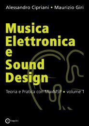
ELECTRONIC MUSIC AND SOUND DESIGN<br />
Theory and Practice <strong>with</strong> Max/MSP - volume 1<br />
by Alessandro Cipriani and Maurizio Giri<br />
© ConTempoNet 2010<br />
full version at:<br />
www.virtual-sound.com<br />
from “Electronic Music and <strong>Sound</strong> Design” Vol. 1 by Alessandro Cipriani and Maurizio Giri<br />
© ConTempoNet 2010 - All rights reserved
Alessandro Cipriani • Maurizio Giri<br />
ELECTRONIC MUSIC AND SOUND DESIGN<br />
Theory and Practice <strong>with</strong> Max/MSP - Vol. 1<br />
from “Electronic Music and <strong>Sound</strong> Design” Vol. 1 by Alessandro Cipriani and Maurizio Giri<br />
© ConTempoNet 2010 - All rights reserved
Cipriani, Alessandro. Giri, Maurizio.<br />
Electronic Music and <strong>Sound</strong> Design : theory and practice <strong>with</strong> Max/MSP. Vol. 1.<br />
/ Alessandro Cipriani, Maurizio Giri.<br />
Includes bibliographical references and index.<br />
ISBN 978-88-905484-0-6<br />
1. Computer Music - Instruction and study. 2. Computer composition.<br />
Original Title: Musica Elettronica e <strong>Sound</strong> Design - Teoria e Pratica con Max/MSP<br />
Copyright © 2009 Contemponet s.a.s. Rome - Italy<br />
Translation by David Stutz<br />
Copyright © 2010 - ConTempoNet s.a.s., Rome - Italy<br />
Figures produced by: Gabriele Cappellani<br />
Interactive Examples: Francesco Rosati<br />
Index: Salvatore Mudanò<br />
Language education consultant: Damiano De Paola<br />
Products and Company names mentioned herein may be trademarks of their<br />
respective Companies. Mention of third-party products is for informational<br />
purposes only and constitutes neither an endorsement nor a recommendation.<br />
The use of general descriptive names, trade names, trademarks, etc., in this<br />
publication, even if the former are not especially identified, is not to be taken<br />
as a sign that such names, as understood by the Trade Marks and Merchandise<br />
Marks Act, may accordingly be used freely by anyone.<br />
All rights reserved. No part of this book may be reproduced in any form by<br />
any electronic or mechanical means (including photocopying, recording, or<br />
information storage and retrieval) <strong>with</strong>out permission in writing from the<br />
publisher.<br />
ConTempoNet s.a.s., Rome (Italy)<br />
URL: www.virtual-sound.com<br />
www.contemponet.com<br />
from “Electronic Music and <strong>Sound</strong> Design” Vol. 1 by Alessandro Cipriani and Maurizio Giri<br />
© ConTempoNet 2010 - All rights reserved
CONTENTS<br />
Foreword by David Zicarelli • VII<br />
Introduction and dedications • IX<br />
Chapter 1T - THEORY<br />
INTRODUCTION TO SOUND SYNTHESIS<br />
LEARNING AGENDA • 2<br />
1.1 <strong>Sound</strong> synthesis and signal processing • 3<br />
1.2 Frequency, amplitude, and waveform • 7<br />
1.3 Changing frequency and amplitude in time: envelopes and glissandi • 24<br />
1.4 The relationship between frequency and musical interval • 34<br />
1.5 Introduction to working <strong>with</strong> sampled sound • 37<br />
1.6 Introduction to panning • 39<br />
Fundamental concepts • 43<br />
Glossary • 45<br />
Chapter 1P - PRACTICE<br />
SOUND SYNTHESIS WITH MAX/MSP<br />
LEARNING AGENDA • 50<br />
1.1 First steps <strong>with</strong> Max/MSP • 51<br />
1.2 Frequency, amplitude, and waveform • 68<br />
1.3 Changing frequency and amplitude in time: envelopes and glissandi • 79<br />
1.4 The relationship between frequency and musical interval • 94<br />
1.5 Introduction to working <strong>with</strong> sampled sound • 99<br />
1.6 Introduction to panning • 104<br />
1.7 Some Max/MSP basics • 107<br />
List of principal commands • 118<br />
List of Max/MSP objects • 121<br />
Commands, attributes, and parameters for some Max/MSP objects • 125<br />
Glossary • 126<br />
Interlude A - PRACTICE<br />
PROGRAMMING WITH MAX/MSP<br />
LEARNING AGENDA • 130<br />
IA.1 Max and the numbers: the binary operators • 131<br />
IA.2 Generating random numbers • 138<br />
IA.3 Managing time: the metro object • 142<br />
IA.4 Subpatches and abstractions • 144<br />
IA.5 Other random number generators • 152<br />
IA.6 Message ordering <strong>with</strong> trigger • 156<br />
IA.7 Objects for managing lists • 160<br />
IA.8 The message box and variable arguments • 165<br />
IA.9 Sending sequences of bangs: the uzi object • 170<br />
IA.10 Send and receive • 170<br />
List of Max/MSP objects • 179<br />
Commands, attributes, and parameters for some Max/MSP objects • 181<br />
Glossary • 183<br />
from “Electronic Music and <strong>Sound</strong> Design” Vol. 1 by Alessandro Cipriani and Maurizio Giri<br />
© ConTempoNet 2010 - All rights reserved<br />
III
IV<br />
Chapter 2T - THEORY<br />
ADDITIVE AND VECTOR SYNTHESIS<br />
LEARNING AGENDA • 186<br />
2.1 Fixed spectrum additive synthesis • 187<br />
2.2 Beats • 212<br />
2.3 Crossfading between wavetables: vector synthesis • 220<br />
2.4 Variable spectrum additive synthesis • 221<br />
Fundamental concepts • 226<br />
Glossary • 227<br />
Discography • 230<br />
Chapter 2P - PRACTICE<br />
ADDITIVE AND VECTOR SYNTHESIS<br />
LEARNING AGENDA • 232<br />
2.1 Fixed spectrum additive synthesis • 233<br />
2.2 Beats • 248<br />
2.3 Crossfading between wavetables: vector synthesis • 252<br />
2.4 Variable spectrum additive synthesis • 259<br />
List of Max/MSP objects • 289<br />
Commands, attributes, and parameters for some Max/MSP objects • 290<br />
Glossary • 291<br />
Chapter 3T - THEORY<br />
NOISE GENERATORS, FILTERS AND SUBTRACTIVE<br />
SYNTHESIS<br />
LEARNING AGENDA • 294<br />
3.1 <strong>Sound</strong> sources for subtractive synthesis • 295<br />
3.2 Lowpass, highpass, bandpass, and bandreject filters • 300<br />
3.3 The Q factor • 308<br />
3.4 Filter order and connection in series • 310<br />
3.5 Subtractive synthesis • 319<br />
3.6 Equations for digital filters • 323<br />
3.7 Filters connected in parallel, and graphic equalization • 331<br />
3.8 Other applications of connection in series: parametric eq and shelving<br />
filters • 339<br />
3.9 Other sources for subtractive synthesis: impulses and resonant bodies • 342<br />
Fundamental concepts • 347<br />
Glossary • 349<br />
Discography • 353<br />
Chapter 3P - PRACTICE<br />
NOISE GENERATORS, FILTERS AND SUBTRACTIVE<br />
SYNTHESIS<br />
LEARNING AGENDA • 356<br />
3.1 <strong>Sound</strong> sources for subtractive synthesis • 357<br />
3.2 Lowpass, highpass, bandpass, and bandreject filters • 362<br />
3.3 The Q factor • 367<br />
3.4 Filter order and connection in series • 373<br />
from “Electronic Music and <strong>Sound</strong> Design” Vol. 1 by Alessandro Cipriani and Maurizio Giri<br />
© ConTempoNet 2010 - All rights reserved<br />
Contents
Electronic Music and <strong>Sound</strong> Design - Contents<br />
3.5 Subtractive synthesis • 384<br />
3.6 Equations for digital filters • 394<br />
3.7 Filters connected in parallel, and graphic equalization • 398<br />
3.8 Other applications of connection in series: parametric eq and shelving<br />
filters • 403<br />
3.9 Other sources for subtractive synthesis: impulses and resonant bodies • 406<br />
List of Max/MSP objects • 416<br />
Commands, attributes, and parameters for specific Max/MSP objects • 419<br />
Interlude B - PRACTICE<br />
ADDITIONAL ELEMENTS OF PROGRAMMING WITH<br />
MAX/MSP<br />
LEARNING AGENDA • 422<br />
IB.1 Introduction to MIDI • 423<br />
IB.2 The modulo operator and recursion • 426<br />
IB.3 Routing signals and messages • 433<br />
IB.4 The relational operators and the select object • 435<br />
IB.5 Reducing a list to its parts: the iter object • 440<br />
IB.6 Iterative structures • 442<br />
IB.7 Generating random lists • 446<br />
IB.8 Calculations and conversions in Max • 447<br />
IB.9 Using arrays as envelopes: Shepard tone • 455<br />
List of Max/MSP objects • 467<br />
Commands, attributes, and parameters for specific Max/MSP objects • 469<br />
Glossary • 470<br />
Chapter 4T - THEORY<br />
CONTROL SIGNALS<br />
LEARNING AGENDA • 472<br />
4.1 Control signals: stereo panning • 473<br />
4.2 DC Offset • 474<br />
4.3 Control signals for frequency • 476<br />
4.4 Control signals for amplitude • 478<br />
4.5 Varying the duty cycle (pulse-width modulation) • 479<br />
4.6 Control signals for filters • 480<br />
4.7 Other generators of control signals • 482<br />
4.8 Control signals: multi-channel panning • 485<br />
Fundamental concepts • 487<br />
Glossary • 489<br />
Chapter 4P - PRACTICE<br />
CONTROL SIGNALS<br />
LEARNING AGENDA • 492<br />
4.1 Control signals: stereo panning • 493<br />
4.2 DC Offset • 495<br />
4.3 Control signals for frequency • 496<br />
4.4 Control signals for amplitude • 502<br />
4.5 Varying the duty cycle (pulse-width modulation) • 503<br />
from “Electronic Music and <strong>Sound</strong> Design” Vol. 1 by Alessandro Cipriani and Maurizio Giri<br />
© ConTempoNet 2010 - All rights reserved<br />
V
VI<br />
4.6 Control signals for filters • 504<br />
4.7 Other generators of control signals • 506<br />
4.8 Control signals: multi-channel panning • 510<br />
List of Max/MSP objects • 523<br />
Commands, attributes, and parameters for specific Max/MSP objects • 523<br />
Glossary • 524<br />
References • 525<br />
Index • 527<br />
from “Electronic Music and <strong>Sound</strong> Design” Vol. 1 by Alessandro Cipriani and Maurizio Giri<br />
© ConTempoNet 2010 - All rights reserved<br />
Contents
Electronic Music and <strong>Sound</strong> Design - Foreword<br />
FOREWORD<br />
by David Zicarelli<br />
It might seem odd to you, but many years ago, I spent a lot of time learning<br />
about making sound <strong>with</strong> a computer by reading books and articles while trying<br />
to imagine what the synthesis techniques being described would actually<br />
sound like. While I suppose my imagination might have been stimulated by this<br />
practice, I am happy that real-time synthesis has progressed to the point where<br />
you no longer have to be deprived of the perceptual experience that is such an<br />
important part of learning the techniques of digital synthesis.<br />
Alessandro Cipriani and Maurizio Giri’s book is one of the first courses on<br />
electronic sound that explicitly integrates perception, theory, and practice using<br />
examples of real-time sound synthesis you can manipulate and experience<br />
for yourself. In my view, the manipulation aspect of learning about sound is<br />
critically important. It helps lead you to what Joel Chadabe terms “predictive<br />
knowledge” -- the ability to intuit what will happen to a sound before you take<br />
an action to change it. We all have some level of predictive knowledge. For<br />
example, most of us know that by turning a volume knob clockwise, the sound<br />
coming from our amplifier will get louder. Once we enter the realm of digital<br />
sound synthesis, things quickly get more complicated than a volume knob, and<br />
we need the first-hand experience of manipulation and perception in order to<br />
deepen our predictive knowledge.<br />
However, to educate ourselves fully about digitally produced sound, we need<br />
more than predictive knowledge. We need to know why our manipulations<br />
make the perceptual changes we experience. This theoretical knowledge<br />
reinforces our intuitive experiential knowledge, and at the same time, our<br />
experience gives perceptual meaning to theoretical explanations.<br />
In my opinion, Cipriani and Giri have done a masterful job of allowing<br />
experiential and theoretical knowledge to reinforce each other. This book will<br />
work either as a textbook or as a vehicle for the independent learner. As a<br />
bonus, the book includes a thorough introduction to digital signal processing<br />
<strong>with</strong> Max/MSP and serves as a wonderful introduction to the <strong>programming</strong><br />
concepts in that software.<br />
As you will see, the theoretical chapters are the “T” chapters, while practical<br />
and experiential knowledge is imparted by the “P” chapters. These chapters<br />
alternate, in the form of a ladder, refining the concepts at ever higher levels of<br />
sophistication.<br />
I hope you will take advantage of the excellent Max/MSP examples the authors<br />
have created. They are simultaneously fun and enlightening, and they sound<br />
good enough to use on stage. They are also worth examining as models for<br />
your own Max/MSP patches, or for extending in new ways. But a few minutes<br />
of messing around <strong>with</strong> the examples is not the same thing as studying the<br />
from “Electronic Music and <strong>Sound</strong> Design” Vol. 1 by Alessandro Cipriani and Maurizio Giri<br />
© ConTempoNet 2010 - All rights reserved<br />
VII
VIII<br />
concepts in the book. The book provides the language for expressing the<br />
concepts in terms of the underlying theory. Knowing the theory is essential,<br />
because presumably you’re reading this book because you want to be more<br />
than someone who can turn a volume knob.<br />
That is the authors’ wish for you, and mine as well. I want to wish you good<br />
luck on this new adventure, and also thank my two Italian friends for creating<br />
such a comprehensive resource for learning about digital music – the one I wish<br />
existed when I was a student!<br />
David Zicarelli, publisher of Max/MSP<br />
from “Electronic Music and <strong>Sound</strong> Design” Vol. 1 by Alessandro Cipriani and Maurizio Giri<br />
© ConTempoNet 2010 - All rights reserved<br />
Foreword
Electronic Music and <strong>Sound</strong> Design - Introduction<br />
INTRODUCTION<br />
This is the first of a series of three volumes dedicated to digital synthesis and<br />
sound design. The second volume will cover a range of additional topics in the<br />
realm of sound synthesis and signal processing, including dynamics processing,<br />
delay lines, reverberation and spatialization, digital audio and sampled sounds,<br />
MIDI, OSC and realtime synthesis. The third volume will be concerned <strong>with</strong> nonlinear<br />
techniques (such as AM and FM synthesis), granular synthesis, analysis<br />
and resynthesis, convolution, physical modeling, micromontage, and computeraided<br />
composition.<br />
PREREQUISITES<br />
This first volume will be useful to several levels of reader. Prerequisites for<br />
its study are minimal, and include nothing more than rudimentary musical<br />
knowledge such as an understanding of notes, scales, and chords, as well as<br />
basic computer skills such as saving files, copying and pasting text.<br />
The volume should be equally useful for self-learners and for those studying<br />
under the guidance of a teacher. It is laid out as chapters of theoretical background<br />
material that are interleaved <strong>with</strong> chapters that contain practical computer<br />
techniques. Each pair of chapters stands together as a unit. We suggest<br />
that curricula follow this structure, first touching on theory, then following up<br />
<strong>with</strong> hands-on material, including computer activities. The theoretical chapters<br />
are not intended to substitute for more expansive texts about synthesis; they<br />
provide, instead, an organic framework for learning the theory that is needed to<br />
invent sounds on the computer and to write signal processing programs.<br />
TIME NEEDED FOR STUDY<br />
The time needed for this material will, of course, vary from person to person.<br />
Nonetheless, here are two estimates to help in planning, one for learning under<br />
the guidance of an expert teacher, and the other for self-learners:<br />
Self-learning<br />
(300 total hours of individual study)<br />
Chapters Topic Total hours<br />
1T+1P+IA <strong>Sound</strong> synthesis 100<br />
2T+2A Additive Synthesis 60<br />
3T+3P+IB Subtractive Synthesis and Filtering 110<br />
4T+4P Control Signals 30<br />
Teacher-assisted learning<br />
(60 hours of classroom-based learning + 120 hours of individual study)<br />
Chapters Topic Lessons Feedback Studio time Total hours<br />
1T+1P+IA <strong>Sound</strong> synthesis 16 4 40 60<br />
2T+2P Additive Synthesis 10 2 24 36<br />
3T+3P+IB Subtractive Synthesis 18 4 44 66<br />
4T+4P Control Signals 5 1 12 18<br />
from “Electronic Music and <strong>Sound</strong> Design” Vol. 1 by Alessandro Cipriani and Maurizio Giri<br />
© ConTempoNet 2010 - All rights reserved<br />
IX
X<br />
THE INTERACTIVE EXAMPLES<br />
The path laid out in the theoretical sections of this book is meant to be<br />
accompanied by numerous interactive examples, which are available on the<br />
website. Using these examples, the reader can immediately refer to the example<br />
sounds being discussed, as well as their design and elaboration, <strong>with</strong>out having<br />
to spend intervening time on the practical work of <strong>programming</strong>. In this way,<br />
the study of theory can be immediately connected to the concrete experience of<br />
sounds. The integration of understanding and experience in the study of sound<br />
design and electronic music is our objective. This principle is the basis for the<br />
entire set of three volumes, as well as for future online materials that will help<br />
to update, broaden, and clarify the existing text.<br />
THEORY AND PRACTICE<br />
As we just said, the teaching approach for this book is based, first and<br />
foremost, upon an interplay between theory and practice, which we believe<br />
is indispensable. One of the glaring problems in the field of digital sound<br />
processing is the knowledge gap that exists between experts in theory (who<br />
often have neither the time nor the need to tackle concrete technical problems<br />
that are so relevant to the actual practice of creating sound) and those<br />
enthusiasts, much more numerous, who love to invent and modify sounds<br />
using their computers. These enthusiasts persevere, despite gaps in their<br />
theoretical awareness and/or in their understanding of how sounds may be<br />
modified <strong>with</strong>in the rigid confines forced upon them by their specific software.<br />
It is our intention help these users of music software to acquire the deeper<br />
understanding that will take them beyond the confines of specific software to<br />
access the profound power inherent in the medium.<br />
TEACHING APPROACH AND METHOD OF THIS BOOK<br />
On the basis of the problems and concepts described above, we have tried<br />
to fill the information gap by continuing in the direction already begun <strong>with</strong><br />
the book titled “<strong>Virtual</strong> <strong>Sound</strong>” (Cipriani and Bianchini), also dedicated to<br />
sound synthesis and signal processing. The innovations in this new text are<br />
substantial, <strong>with</strong> regard to both the examples provided and a completely<br />
different teaching approach. Because very little academic literature is available<br />
concerning methods for teaching electronic music, we have approached the<br />
problem directly, considering various promising ways to plumb the depths of<br />
the subject material. This exercise has led us to an organic teaching method, in<br />
which we adopt various ideas and techniques from foreign language textbooks<br />
in order to develop a more context-based, open-ended and interactive concept<br />
of teaching and learning.<br />
In addition to interactive examples, we have included “learning agendas” that<br />
detail the specific objectives for each chapter, that include listening and analysis<br />
activities, exercises and tests, glossaries, and suggestions for recordings to<br />
which to listen. The practical chapters of the book also include many other<br />
new features and activities, including the correction, completion, implementation,<br />
debugging, testing and analysis of algorithms, the construction of new<br />
from “Electronic Music and <strong>Sound</strong> Design” Vol. 1 by Alessandro Cipriani and Maurizio Giri<br />
© ConTempoNet 2010 - All rights reserved<br />
Introduction
Electronic Music and <strong>Sound</strong> Design - Introduction<br />
algorithms from scratch, the replacement of parts of pre-built algorithms, and<br />
reverse engineering (in which the reader listens to a sound and then tries to<br />
invent an algorithm to create a similar sound).<br />
These activities and tasks are intended to activate the knowledge and practical<br />
skills of the reader. When learning a foreign language, there is a gap between<br />
what one knows and what one is able to use in practice. It is common for a<br />
student’s passive vocabulary (the total number of terms that the student can<br />
recognize) to be much larger than the active vocabulary that he or she can actually<br />
use while speaking or writing. The same is true of a <strong>programming</strong> language:<br />
a student can understand how algorithms work <strong>with</strong>out being able to build<br />
them from scratch. The activities in this book that concentrate on replacing<br />
parts of algorithms, completing unfinished algorithms, correcting algorithms<br />
<strong>with</strong> bugs, and reverse engineering, have been included in order to pose problems<br />
to which the reader is encouraged to find his or her own solutions, causing<br />
the learning process to become more active and creative.<br />
When learning a foreign language, students are given replacement exercises<br />
(e.g. “replace the underlined verb in the following phrase: I wish I could go<br />
out”), correction exercises (e.g. “correct the following phrase: I want to went<br />
home”), and sentences to be completed (e.g. “I’d like to ... home”). In this<br />
context, it is vitally important for the student to work at these activities in order<br />
to avoid an excessively passive approach to learning. Our approach, likewise,<br />
not only involves interactions between the perception of sounds and the knowledge<br />
deriving from reading the book and doing the practical activities, but also<br />
interactions between these two factors and the user’s own skills and creativity.<br />
This method is not based on a rigidly linear progression, but is rather a<br />
network that enables the reader to acquire knowledge and practical skills<br />
through an interaction of four separate dimensions: learning of the theoretical<br />
concepts, learning to use the Max/MSP program, interacting <strong>with</strong> example<br />
material, and constructing algorithms.<br />
MAX/MSP<br />
The practical parts of this book are based on the software Max/MSP. This<br />
program, written originally by Miller Puckette, was extensively revised and<br />
expanded by David Zicarelli, and is published as a supported product by Cycling<br />
’74 (www.cycling74.com). Max/MSP is an interactive graphic environment for<br />
music, audio processing, and multimedia. It is used throughout the world by<br />
musicians, composers, sound designers, visual artists, and multimedia artists,<br />
and it has become a de facto standard for modern technologically-enabled<br />
creative projects in both the musical and in the visual spheres.<br />
It is a graphic <strong>programming</strong> language, and is therefore relatively easy to learn,<br />
especially given its great power and expressivity. In Max/MSP one creates programs<br />
by connecting onscreen graphic objects <strong>with</strong> virtual cables. These objects<br />
can perform calculations, produce or process sounds, render visuals, or be<br />
configured as a graphical user interface. Using its sound synthesis and signal<br />
processing capabilities, one can fashion soft-synths, samplers, reverbs, signalprocessing<br />
effects, and many other things.<br />
from “Electronic Music and <strong>Sound</strong> Design” Vol. 1 by Alessandro Cipriani and Maurizio Giri<br />
© ConTempoNet 2010 - All rights reserved<br />
XI
XII<br />
In practice, Max/MSP adopts the metaphor of the modular synthesizer: each<br />
module handles a particular function, exchanging data <strong>with</strong> the modules to<br />
which it is connected. The difference between a traditional modular synthesizer<br />
and Max/MSP is that <strong>with</strong> Max/MSP, one can access and control a level of detail<br />
that would be inconceivable in a preconfigured synthesizer or extension module<br />
(whether hardware or software).<br />
PRACTICAL INFORMATION<br />
Many indispensable materials accompany this book, among them, interactive<br />
examples, patches (programs written in Max/MSP), sound files, <strong>programming</strong><br />
libraries, and other materials.<br />
These can be found at the book web site.<br />
Interactive Examples<br />
During the study of a theory chapter, before moving on to the related practical<br />
chapter, it will help to use the interactive examples. Working <strong>with</strong> these<br />
examples will aid in the assimilation of the concepts raised by the theory.<br />
Example Files<br />
The example files (patches), are created to be used <strong>with</strong> Max/MSP version<br />
5 or higher, which is downloadable from the official Cycling ‘74 website,<br />
www.cycling74.com.<br />
Alternating Theory and Practice<br />
In this book, theoretical chapters alternate <strong>with</strong> chapters which are geared<br />
towards <strong>programming</strong> practice. Because of this, the reader will find himself taking<br />
on all of the theory for a given chapter before passing to the corresponding<br />
practical chapter. An alternative to this approach would be to read a single section<br />
from the theory, and then go directly to the corresponding section of the<br />
practical chapter. (For example, 1.1T and 1.1P, then 1.2T and 1.2P, etc.<br />
The Interludes<br />
Note that there are two “technical interludes”, the first between the first<br />
and second chapters, and the second between the third and fourth chapters.<br />
These interludes, named respectively “Interlude A” and “Interlude B”, are<br />
dedicated specifically to the Max/MSP language. They don’t relate directly to<br />
any of the theoretical discussions, but they are very necessary for following<br />
the code traced out in the book. After having tackled the theory and practice<br />
of the first chapter, before moving on to the second chapter, it will benefit<br />
the reader to study Interlude A. Likewise, Interlude B is meant to be studied<br />
between Chapters 3 and 4.<br />
Learning Max/MSP<br />
Learning Max/MSP (and, in general, learning synthesis and sound processing)<br />
requires effort and concentration. In contrast to much commercial music<br />
software, Max/MSP provides flexibility to the programmer, and this design<br />
choice provides those <strong>programming</strong> <strong>with</strong> Max/MSP many alternative ways to<br />
build a given algorithm. To benefit from this freedom, however, it is advisable<br />
from “Electronic Music and <strong>Sound</strong> Design” Vol. 1 by Alessandro Cipriani and Maurizio Giri<br />
© ConTempoNet 2010 - All rights reserved<br />
Introduction
Electronic Music and <strong>Sound</strong> Design - Introduction<br />
to consider the recommendations of the book and to code in a systematic<br />
way. Max/MSP is a true musical instrument, and learning to play it should be<br />
approached as one would approach the study of a traditional instrument (such<br />
as a violin). As <strong>with</strong> any instrument, the reader will find it necessary to practice<br />
regularly, and to stay sharp on basics while gradually acquiring more complex<br />
techniques. By approaching the software in this way, fundamental techniques<br />
and technical insights can be retained once they have been acquired.<br />
Bibliography<br />
The decision was made to limit the bibliography in this book to a list of only the<br />
most absolutely essential reference works, and, of course, a list of the books and<br />
articles cited in the text. A more comprehensive bibliography is available online.<br />
Before Beginning<br />
To begin working <strong>with</strong> this book, you will need to download the interactive <strong>programming</strong><br />
examples, which you will find at the support page for this text. While<br />
reading the theory chapters, you will find constant references to the examples<br />
contained in this downloadable archive. To work interactively <strong>with</strong> the <strong>programming</strong><br />
chapters of the book, you will need to download the <strong>Virtual</strong> <strong>Sound</strong> Macro<br />
Library from the support page mentioned above. It will also be necessary to install<br />
MaxMSP, which is available at the Cycling74 website: www.cycling74.com.<br />
The same web page contains detailed instructions regarding how to install MaxMSP<br />
and the macro library correctly; look for the document entitled “How to Install and<br />
Configure MaxMSP”.<br />
Always check the support page for patches (MaxMSP programs) related to<br />
the practice chapters of this book, as well as the audio files for the reverse<br />
engineering exercises.<br />
THANKS<br />
We wish to thank Gabriele Cappellani, Salvatore Mudanò and Francesco<br />
“Franz” Rosati for their patience and long hours of work, and Dario Amoroso,<br />
Joel Chadabe, Mirko Ettore D’Agostino, Luca De Siena, Eugenio Giordani,<br />
Gabriele Paolozzi, Giuseppe Emanuele Rapisarda, Fausto Sebastiani, Alvise<br />
Vidolin and David Zicarelli for their generosity.<br />
DEDICATIONS<br />
This text is dedicated to Riccardo Bianchini, who would have wanted to participate<br />
in the production of this teaching text, but who, unfortunately, passed<br />
away before the work began. We have collected some of his materials, revised<br />
them, and cited them in a few of the sections on theory. This seemed to be<br />
a way to have Riccardo still <strong>with</strong> us. A particular thanks goes to Ambretta<br />
Bianchini for her great generosity and sensitivity during these years of work.<br />
Alessandro Cipriani and Maurizio Giri<br />
from “Electronic Music and <strong>Sound</strong> Design” Vol. 1 by Alessandro Cipriani and Maurizio Giri<br />
© ConTempoNet 2010 - All rights reserved<br />
XIII
1T<br />
INTRODUCTION TO SOUND SYNTHESIS<br />
1.1 SOUND SYNTHESIS AND SIGNAL PROCESSING<br />
1.2 FREQUENCY, AMPLITUDE, AND WAVEFORM<br />
1.3 CHANGING FREQUENCY AND AMPLITUDE IN TIME: ENVELOPES AND<br />
GLISSANDI<br />
1.4 THE RELATIONSHIP BETWEEN FREQUENCY AND MUSICAL INTERVAL<br />
1.5 INTRODUCTION TO WORKING WITH SAMPLED SOUND<br />
1.6 INTRODUCTION TO PANNING<br />
from “Electronic Music and <strong>Sound</strong> Design” Vol. 1 by Alessandro Cipriani and Maurizio Giri<br />
© ConTempoNet 2010 - All rights reserved<br />
INTRODUCTION TO SOUND SYNTHESIS �
LEARNING AGENDA 1T<br />
PREREQUISITES FOR THE CHAPTER<br />
• Basic skills in using computers<br />
(operating a computer, managing files and folders, audio formats, etc.)<br />
• minimal knowledge of music theory (semitones, octaves, rhythms, etc.)<br />
LEARNING OBJECTIVES<br />
Knowledge<br />
• to learn aBout the signal paths one uses in sound synthesis and signal processing<br />
• to learn aBout the principal parameters of sound and their characteristics<br />
• to learn how pitch and sound intensity are digitally encoded<br />
• to learn aBout musical intervals in different tuning systems<br />
• to learn aBout audio file formats<br />
SKillS<br />
• to Be aBle to hear changes of frequency and amplitude and to descriBe their<br />
characteristics<br />
• to Be aBle to hear the stages of the envelope of a sound or a glissando<br />
CONTENTS<br />
• computer-Based sound synthesis and signal processing<br />
• theory of timBre, pitch, and sound intensity<br />
• theory of glissandi and amplitude envelopes<br />
• the relationship Between frequency, pitch, and midi encoding<br />
• introduction to sampled sound<br />
• introduction to panning<br />
ACTIVITIES<br />
• interactive examples<br />
TESTING<br />
• questions <strong>with</strong> short answers<br />
• listening and analysis<br />
SUPPORTING MATERIALS<br />
• fundamental concepts<br />
• glossary<br />
from “Electronic Music and <strong>Sound</strong> Design” Vol. 1 by Alessandro Cipriani and Maurizio Giri<br />
© ConTempoNet 2010 - All rights reserved
Chapter 1T - Introduction to sound synthesis<br />
1.1 SOUND SYNTHESIS AND SIGNAL PROCESSING<br />
The use of computers in music has enabled composers and musicians to manage<br />
and manipulate sound <strong>with</strong> a precision and a freedom that is unthinkable <strong>with</strong><br />
acoustic instruments. Thanks to the computer, it is now possible to model<br />
sound in every way imaginable. One might say that while the traditional<br />
composer working <strong>with</strong> traditional instruments composes using sounds, the<br />
electronic composer composes the sounds themselves.<br />
The same thing has happened in animation graphics: thanks to the computer it<br />
is now possible to create images and film sequences that are extremely realistic,<br />
and that would have been impossible to produce by other means. Almost all<br />
cinematic special effects are now produced <strong>with</strong> computers; it is becoming commonplace<br />
to find virtual entities sharing the screen <strong>with</strong> flesh-and-blood actors.<br />
These newfound possibilities are the result of passing from the analog world<br />
into the digital world. The digital world is a world of numbers. Once an image or<br />
a sound has been converted into a sequence of numbers, those numbers can be<br />
subjected to transformations, since numbers are easily and efficiently analyzed<br />
and manipulated by computers. The process of digitization, precisely defined as<br />
that of transforming an item of data (a text, a sound, an image) into a sequence<br />
of numbers, is the technique that makes this all possible. 1<br />
This text will concentrate on two subjects: sound synthesis and signal processing.<br />
<strong>Sound</strong> synthesis means the electronic generation of sound. In practice, you will<br />
find that the possibilities for creating sound are based largely on a few selected<br />
parameters, and that you can obtain the sonorities you seek by manipulating these<br />
parameters.<br />
Signal processing in this context means the electronic modification of a sound,<br />
whether the sound of a recorded guitar or a sound generated by using a particular<br />
type of sound synthesis.<br />
DIGITAL SYNTHESIS OF SOUND<br />
When generating sound using a <strong>programming</strong> language designed for sound<br />
synthesis and signal processing, we specify a desired sound by constructing a<br />
“virtual machine” of our own design (realized as an algorithm 2 ) , and by specifying<br />
a series of instructions which this machine will use to create the sound.<br />
Once we have written this sequence of instructions, the <strong>programming</strong><br />
language we’re using (Max/MSP for example) will execute our instructions<br />
to create a stream of digital data in which all of the characteristics of the<br />
1 We will broaden this concept during the course of the chapter.<br />
2 An algorithm is a sequence of instructions, written in a <strong>programming</strong> language, that enables a<br />
computer to carry out a defined task.<br />
from “Electronic Music and <strong>Sound</strong> Design” Vol. 1 by Alessandro Cipriani and Maurizio Giri<br />
© ConTempoNet 2010 - All rights reserved<br />
1T<br />
3
1.1<br />
4<br />
Theory<br />
sound or sounds that we have specified will be rendered. 3 Between the<br />
time that this stream of digital data is generated and the time that we actually<br />
hear the sound, another fundamental operation occurs. The computer’s<br />
audio interface transforms the digital data into an electrical signal that,<br />
when fed to an amplifier and loudspeakers, will produce the sound. The<br />
audio interface, in other words, converts the digital data into an analog voltage<br />
(a process often abbreviated as “D/A conversion”), allowing us to hear<br />
the sounds that are represented by the stream of digital data. (Fig. 1.1).<br />
Fig. 1.1 Realtime synthesis<br />
We can also capture the stream of data to our hard disk as an audio file, which<br />
will enable us to hear the result of our algorithmic processing as many times as<br />
we’d like.<br />
When the stream of data goes directly to the audio interface as it is processed,<br />
so that there are only few milliseconds between the processing and the listening<br />
of the synthesized sound, one speaks of realtime synthesis. When the<br />
processing of sound is first calculated entirely and saved to an audio file (which<br />
can be listened to later) one speaks of non-realtime or offline synthesis. (In<br />
this context the latter term is not a technical one, but it is widely used.)<br />
Fig. 1.2 Non-realtime synthesis and listening as separate actions<br />
3 In numeric form.<br />
���������<br />
�������<br />
���������<br />
Paragraph 1.1 - <strong>Sound</strong> synthesis and signal processing<br />
������<br />
�������������<br />
�������<br />
���������<br />
��������<br />
��������<br />
������<br />
�������������<br />
���������<br />
from “Electronic Music and <strong>Sound</strong> Design” Vol. 1 by Alessandro Cipriani and Maurizio Giri<br />
© ConTempoNet 2010 - All rights reserved
Chapter 1T - Introduction to sound synthesis<br />
SIGNAL PROCESSING<br />
Signal processing is the act of modifying a sound produced by a live source, for<br />
example through a microphone, or from a pre-existing audio file already stored<br />
in your computer. It is possible to do signal processing in various ways. We see<br />
three possibilities:<br />
Pre-existing sound, saved separately as a sound file which is processed offline<br />
The sound of a flute, for example, is recorded to disk using a microphone connected<br />
to the audio interface, which performs the analog-to-digital conversion. 4<br />
We implement an algorithm in which we specify the sonic modifications to be<br />
made to the original audio file. Once executed, this program will create a new<br />
audio file containing the now-modified sound of the flute. We can then listen<br />
to the processed sound file at any time by playing the file (through the audio<br />
interface).<br />
������<br />
�������������<br />
��������<br />
���������<br />
��������<br />
���������<br />
Fig. 1.3 Example of offline sound processing<br />
Pre-recorded sound, which is then processed in realtime<br />
A sound, already recorded in the computer as in the first example, is streamed<br />
from a pre-existing sound file. The processing program, while executing commands<br />
to modify the streamed sound file, also routes the processed sound file<br />
directly to the audio interface for listening. The program, although it is processing<br />
in real time, can also record the resulting stream into an audio file for later<br />
listening, as in Fig. 1.4.<br />
Realtime sound, processed immediately<br />
���������<br />
���������<br />
�������<br />
���������<br />
<strong>Sound</strong> comes from a live source. As in the preceding example, the processing<br />
program, executing commands, routes the processed sound directly to the<br />
audio interface.<br />
4 A transformation of a physical sound into a sequence of numbers.<br />
from “Electronic Music and <strong>Sound</strong> Design” Vol. 1 by Alessandro Cipriani and Maurizio Giri<br />
© ConTempoNet 2010 - All rights reserved<br />
��������<br />
������<br />
�������������<br />
���������<br />
���������<br />
1T<br />
5
1.1<br />
6<br />
Theory<br />
������<br />
�������������<br />
��������<br />
���������<br />
Paragraph 1.1 - <strong>Sound</strong> synthesis and signal processing<br />
��������<br />
���������<br />
Fig. 1.4 Example of realtime sound processing on pre-existing sound<br />
Naturally, in this case also, the program can record the processed sound as an<br />
audio file, as shown in Figure 1.5.<br />
����������������<br />
���������������<br />
�������<br />
���������<br />
������<br />
�������������<br />
�������<br />
���������<br />
Fig. 1.5 Example of realtime sound processing on live sound<br />
We define a DSP system as an integrated hardware and software system<br />
(computer, audio interface, <strong>programming</strong> language.) that enables the<br />
processing and/or synthesis of sound. The term DSP is an acronym for digital<br />
signal processing.<br />
REALTIME VERSUS OFFLINE PROCESSING<br />
����������<br />
����������<br />
We have seen that both synthesis and signal processing can occur either in<br />
realtime or offline. At first glance, the more valuable approach would seem<br />
to be realtime, because this method provides immediate feedback and an<br />
opportunity to weigh the appropriateness of the algorithm being evaluated,<br />
as well as to tune and tweak the code if necessary.<br />
What cause is served, then, by deferring processing to offline status?<br />
The first reason is simple: to implement algorithms that the computer cannot<br />
execute in realtime, due to their complexity. If, for example, the computer<br />
needs two minutes of time in order to synthesize or to process one minute<br />
from “Electronic Music and <strong>Sound</strong> Design” Vol. 1 by Alessandro Cipriani and Maurizio Giri<br />
© ConTempoNet 2010 - All rights reserved<br />
��������<br />
����������<br />
����������<br />
��������
Chapter 1T - Introduction to sound synthesis<br />
of sound, one has no alternative but to record the result to disk in order to<br />
be able to listen to it <strong>with</strong>out interruption once the processing has finished.<br />
At the dawn of computer music, all of the processing done for synthesis and<br />
effects was performed offline, because the processing power to do realtime<br />
calculation did not exist. With the increasing power of computers, it began to<br />
be possible to perform some processing directly in realtime, and, over time,<br />
the processing power of personal computers grew enormously, enabling them<br />
to do most synthesis and processing in realtime. But as computing power<br />
continues to grow, new possibilities are continually imagined, some of which<br />
are so complex that they can only be achieved offline. The need for offline<br />
processing will never disappear.<br />
There also exists a second reason: a category of processing that is conceptually<br />
offline, independent of the power of the computer. If we want, for example,<br />
to implement an algorithm that, given a sequence of musical sounds from an<br />
instrument, will first break the sequence down into singles notes and then<br />
reorder those notes, sorting from the lowest to the highest pitch, we must do<br />
this processing offline. To realize this algorithm, we would first need the entire<br />
sequence, most likely recorded into an audio file in a way that the computer<br />
could analyze; the algorithm could then separate the lowest note, then the<br />
next-lowest, and so forth until finished. It should be obvious that this kind of<br />
analysis can only take place offline, only after the completion of the entire<br />
sequence; a computer that could handle this kind of algorithm in realtime<br />
(that is to say, while the instrument was playing the sequence) would be a<br />
computer so powerful that it could see into the future!<br />
A final advantage of non-realtime processing is the prospect of saving time!<br />
Contrary to what one might initially think, realtime processing is not the fastest<br />
computing speed possible. We can imagine, for example, that we might<br />
modify a 10 minutes sound file using a particular type of processing. If this<br />
modification were to happen in realtime, it would obviously take 10 minutes,<br />
but we might also imagine that our computer had enough power to render<br />
this processing offline in 1 minute. In other words, the computer could render<br />
the calculations for this particular hypothetical operation at a speed 10 times<br />
faster than realtime. Offline processing, in this case, would be far more convenient<br />
than realtime processing.<br />
1.2 FREQUENCY, AMPLITUDE, AND WAVEFORM<br />
Frequency, amplitude and waveform are three basic parameters of sound. 5 Each<br />
one of these parameters influences how we perceive sound, and in particular:<br />
a) our ability to distinguish a lower pitch from a higher one (frequency)<br />
b) our ability to distinguish a loud sound from a soft sound (amplitude)<br />
c) our ability to distinguish different timbres (waveform)<br />
5 We refer here to the simplest forms of sound. (i.e. we will later see how the parameter of timbre<br />
actually depends on several factors.)<br />
from “Electronic Music and <strong>Sound</strong> Design” Vol. 1 by Alessandro Cipriani and Maurizio Giri<br />
© ConTempoNet 2010 - All rights reserved<br />
1T<br />
7
1.2<br />
8<br />
Theory<br />
Let’s look at a table (taken from Bianchini, R., 2003) of the correspondences<br />
between the physical features of sound, musical parameters, and perceived<br />
sonority.<br />
CHARACTERISTIC PARAMETER PERCEPTUAL SENSATION<br />
Frequency Pitch High � Low<br />
Amplitude Intensity Forte � Piano<br />
Waveform Timbre <strong>Sound</strong> color<br />
TABLE A: correspondences between sound characteristics, musical parameters<br />
and perceived sonority.<br />
FREQUENCY<br />
Paragraph 1.2 - Frequency, amplitude, and waveform<br />
Frequency is the physical parameter that determines the pitch of a sound, that<br />
is, it is the feature that allows us to distinguish between a high-pitched sound<br />
and a low-pitched sound. The range of frequencies that is audible to humans<br />
extends from about 20 to about 20,000 hertz, that is to say, from about 20 to<br />
about 20,000 cycles per second. 6 (We’ll define cycles per second in a moment.)<br />
The higher the frequency of a sound, the higher its pitch will be.<br />
But what do we mean by hertz or “cycles per second”? To understand this, we<br />
refer to the definition of sound given by Riccardo Bianchini:<br />
“The term ‘sound’ signifies a phenomenon caused by a mechanical perturbation<br />
of a transmission medium (usually air) which contains characteristics that can be<br />
perceived by the human ear. 7 Such a vibration might be transmitted to the air,<br />
for example, by a vibrating string (see fig. 1.6). The string moves back and forth,<br />
and during this movement it pushes the molecules of air together on one side,<br />
while separating them from each other on the other side. When the motion of<br />
the string is reversed, the molecules that had been pushed together are able to<br />
move away from each other, and vice versa.<br />
The compressions and expansions (that is to say, the movements of air molecules)<br />
propagate through the air in all directions. Initially, the density of<br />
6 The highest frequency that someone can hear varies from individual to individual. Age is also a<br />
factor. As we get older, our ears become less sensitive to high frequencies.<br />
7 There are many theories about the nature of sound: Roberto Casati and Jérôme Dokic argue that<br />
the air is a medium through which the sound is transmitted, but that sound itself is a localized<br />
event that resonates in the body, or in the mechanical system that produces the vibration. (Casati,<br />
R., Dokic, J. 1994). Another point of view is expressed by Frova: “<strong>with</strong> the term ‘sound’, one<br />
ought to signify the sensation, as manifest in the brain, of a perturbation of a mechanical nature,<br />
of an oscillatory character, which affects the medium interposed between source and listener.”<br />
(Frova, A., 1999, p.4).<br />
from “Electronic Music and <strong>Sound</strong> Design” Vol. 1 by Alessandro Cipriani and Maurizio Giri<br />
© ConTempoNet 2010 - All rights reserved
Chapter 1T - Introduction to sound synthesis<br />
molecules in air is constant; each unit of volume (for example, a cubic centimeter)<br />
contains the same number of molecules.<br />
Fig. 1.6 Vibration of a string<br />
This density can be expressed as a value called pressure. Once the air is disturbed,<br />
the pressure value is no longer constant, but varies from point to point,<br />
increasing where molecules are pushed together and decreasing where the<br />
density of the molecules is rarefied (see Fig. 1.7).<br />
Fig.1.7 Compression and rarefaction of air molecules<br />
Pressure can be physically studied either in terms of space (by simultaneously<br />
noting the pressure at multiple points at a given moment), or from the point of<br />
from “Electronic Music and <strong>Sound</strong> Design” Vol. 1 by Alessandro Cipriani and Maurizio Giri<br />
© ConTempoNet 2010 - All rights reserved<br />
1T<br />
9
1.2<br />
10<br />
Theory<br />
time (by measuring the pressure at a single location as a function of time). For<br />
example, we can imagine that if we were located at a specific point in space,<br />
we might observe a series of condensations and rarefactions of the air around<br />
us, as in Figure 1.8.<br />
pressure<br />
� ��<br />
���<br />
���<br />
� �<br />
Paragraph 1.2 - Frequency, amplitude, and waveform<br />
Fig.1.8 A graphical representation of compression and rarefaction<br />
� �<br />
At time t -1 , which occurs immediately before t 0, the air pressure has its normal<br />
value, since the cyclic disturbance has not yet reached our point of observation.<br />
At instant t 0, the disturbance arrives at our observation point, pressure starts to<br />
rise, reaches a <strong>max</strong>imum value at time t 1 , and then decreases until it returns to<br />
normal at time t 2 . It continues to decline, reaching its minimum value at t 3 , after<br />
which pressure returns to its normal value at t 4 ; the pattern then repeats. What<br />
has been described is a phenomenon called a cycle, and an event that always<br />
repeats in this way is called periodic. 8 The time required to complete a cycle is<br />
said to be the period of the wave, which is indicated by the symbol T and is<br />
measured in seconds (s) or in milliseconds (ms). The number of cycles that are<br />
completed in a second is defined as frequency, and is measured in hertz (Hz) or<br />
cycles per second (cps).<br />
If, for example, a sound wave has period T = 0.01s (1/100 of a second), its frequency<br />
will be 1/T = 1/0.01 = 100 Hz (or 100 cycles per second).”(ibid)<br />
While examining Figure 1.9, listen to the sounds of Interactive Example 1A. 9<br />
We can see (and hear) that increasing the number of cycles per second (Hz)<br />
corresponds to making a sound higher in pitch.<br />
8 Mathematically a waveform is said to be periodic if it is repeated regularly for an infinite time. In<br />
the practice of music, of course, we can satisfy ourselves <strong>with</strong> periods much shorter than infinity!<br />
We will say that a wave is “musically periodic” when it displays enough regularity to induce a<br />
perception of pitch that corresponds to the period of the wave. We’ll discuss this issue in more<br />
detail in Chapter 2.<br />
9 Please note that interactive examples and other supporting materials to the book can be found<br />
on the website.<br />
from “Electronic Music and <strong>Sound</strong> Design” Vol. 1 by Alessandro Cipriani and Maurizio Giri<br />
© ConTempoNet 2010 - All rights reserved<br />
� �<br />
� �<br />
� �
Chapter 1T - Introduction to sound synthesis<br />
amp amp amp amp<br />
�<br />
���<br />
�<br />
����<br />
��<br />
��<br />
�<br />
���<br />
�<br />
����<br />
��<br />
��<br />
�<br />
���<br />
�<br />
����<br />
��<br />
��<br />
�<br />
���<br />
�<br />
����<br />
��<br />
�<br />
time in msec<br />
� � � � ��<br />
Fig.1.9 Four sounds of different frequencies<br />
INTERACTIVE EXAMPLE 1A • FREQUENCY<br />
From the instant that it propagates in space, a wave has a length that is inversely<br />
proportional to its frequency. Let’s clarify this concept: the speed of sound<br />
in air (the speed at which waves propagate from a source) is about 344 meters<br />
per second. 10 This means that a hypothetical wave of 1 Hz would have a length<br />
of about 344 meters, because when it has completed one cycle, one second<br />
will have passed, and during this second, the wavefront will have traveled 344<br />
meters. A wave of 10 Hz, however, completes 10 cycles in a single second,<br />
which fill 344 meters <strong>with</strong> an arrangement of 10 cycles of 34.4 meters each;<br />
each cycle physically occupies a tenth of the total space available.<br />
10 For the record, this speed is reached when the temperature is 21°C (69,8°F). The speed of<br />
sound is, in fact, proportional to the temperature of the medium.<br />
from “Electronic Music and <strong>Sound</strong> Design” Vol. 1 by Alessandro Cipriani and Maurizio Giri<br />
© ConTempoNet 2010 - All rights reserved<br />
100 Hz<br />
200 Hz<br />
1000 Hz<br />
4000 Hz<br />
8<br />
1T<br />
11
1.2<br />
12<br />
Theory<br />
By the same reasoning, a 100 Hz wave has a wavelength of 3.44 meters. We<br />
see that frequency decreases <strong>with</strong> increasing wavelength, and the two quantities<br />
are, as we have said, inversely proportional.<br />
AMPLITUDE<br />
The second key parameter for sound is amplitude, which expresses information<br />
about variations in sound pressure, and which allows us to distinguish a loud<br />
sound from one of weaker intensity.<br />
A sound pressure that is weaker than the human ear can hear is said to lie<br />
below the threshold of hearing, while the <strong>max</strong>imum sound pressure that can<br />
be tolerated by the human ear is defined as the threshold of pain. Exposure<br />
to sounds above the threshold of pain results in physical pain and permanent<br />
hearing damage.<br />
In the wave depicted in Figure 1.10, the <strong>max</strong>imum pressure value is called the<br />
peak amplitude of the sound wave, while the pressure at any point is called<br />
instantaneous amplitude.<br />
When we generically refer to the “amplitude of a sound”, we are referring to<br />
the peak amplitude for the entire sound (see Figure 1.10).<br />
amplitude<br />
�<br />
�<br />
��<br />
Fig.1.10 Amplitude of a sound<br />
� �<br />
Paragraph 1.2 - Frequency, amplitude, and waveform<br />
� ��������������<br />
�����������������������<br />
��� �<br />
�� �<br />
�<br />
��� �<br />
���<br />
�<br />
��������������<br />
���������<br />
If we show a wave that has a peak amplitude of 1, as in the example, we will see<br />
a wave that starts from an instantaneous amplitude of 0 (at time t 0 ), rises to 1 at<br />
time t 1 , returns to pass through 0 at time t 2 , continues to drop until it reaching<br />
its minimum value of -1 at time t 3 , after which it rises again to the value 0 at<br />
time t 4 , and so on. When we represent amplitude this way, we are looking at it<br />
as a function of time. The process of digitization transforms such a function into<br />
a series of numbers between 1 and -1, and the numbers thus obtained can be<br />
used to graph the wave form (Fig. 1.11). The relative position that a wave cycle<br />
from “Electronic Music and <strong>Sound</strong> Design” Vol. 1 by Alessandro Cipriani and Maurizio Giri<br />
© ConTempoNet 2010 - All rights reserved<br />
��<br />
��������������<br />
���������
Chapter 1T - Introduction to sound synthesis<br />
occupies at a given instant is called its phase, and we will explore the concept<br />
of phase in more detail in Section 2.1.<br />
pressure values<br />
Fig. 1.11 Digital representation of a waveform<br />
Comparing the graph to the real wave (i.e. the physical succession of air<br />
compressions and rarefactions), we can see that compression corresponds to<br />
positive numbers, rarefaction to negative numbers, and that the number 0<br />
indicates the original stable pressure. (The absence of any signal is, in fact,<br />
digitally represented by a sequence of zeros.) Values representing magnitude<br />
(or amplitude values) are conventionally expressed as decimal numbers that vary<br />
between 0 and 1. If we represent the peak amplitude <strong>with</strong> a value of 1, we will<br />
have oscillations between 1 and -1 (as in the previous example), whereas if we<br />
were to use 0.5 as the peak amplitude (defined as half of the <strong>max</strong>imum possible<br />
amplitude), we would have oscillations between the numbers 0.5 and -0.5, and<br />
so on. (See figure 1.12.)<br />
amp amp<br />
�<br />
���<br />
���<br />
���<br />
���<br />
���<br />
���<br />
���<br />
���<br />
���<br />
�<br />
����<br />
����<br />
����<br />
����<br />
����<br />
����<br />
����<br />
����<br />
����<br />
��<br />
�<br />
���<br />
�<br />
����<br />
��<br />
�<br />
���<br />
�<br />
����<br />
��<br />
� �� �� �� ���<br />
time in msec<br />
� �� �� �� �� ��<br />
time in msec<br />
Fig.1.12 Two sounds <strong>with</strong> differing amplitudes<br />
from “Electronic Music and <strong>Sound</strong> Design” Vol. 1 by Alessandro Cipriani and Maurizio Giri<br />
© ConTempoNet 2010 - All rights reserved<br />
1T<br />
13
1.2<br />
14<br />
Theory<br />
If the amplitude of a wave being output by an algorithm exceeds the <strong>max</strong>imum<br />
permitted by the audio interface (a wave, for example, that ranges between<br />
1.2 and -1.2, being output by an interface that cannot accurately play values<br />
greater than 1), all of the values exceeding 1 or falling below -1 will be limited<br />
respectively to the <strong>max</strong>imum and the minimum value: offending values will be<br />
“clipped” to the values 1 or -1. Clipped waves are deformed, and because of<br />
this, their sound is distorted 11 (see fig. 1.13).<br />
amplitude<br />
�<br />
���<br />
�<br />
����<br />
��<br />
Fig.1.13 A “clipped” waveform<br />
� � � � � ��<br />
time in msec<br />
Paragraph 1.2 - Frequency, amplitude, and waveform<br />
In most software, besides using “raw” numbers to represent amplitude, it is<br />
also possible to indicate levels by using dB SPL: the symbol dB indicates that<br />
the level is to measured in deciBels, and the acronym SPL stands for <strong>Sound</strong><br />
Pressure Level. Whereas raw amplitude measurements represent the difference<br />
between a sound pressure measurement and some normal pressure, SPL is<br />
instead defined as the relationship of a sound pressure at a given moment to a<br />
reference pressure (which is typically 0 dB in digital audio). 0 dB SPL represents<br />
the highest level of accurately reproducible pressure (corresponding to the <strong>max</strong>imum<br />
amplitude), and lower levels are indicated by negative values.<br />
Using this scale, the raw amplitude 1, as used in the preceding examples,<br />
would correspond to 0 dB SPL, while a magnitude of 0.5 would correspond<br />
to approximately -6 dB, and an amplitude of 0.25 would fall still lower on the<br />
scale at approximately -12 dB. It follows that a reduction of 6 dB corresponds<br />
to a halving of the amplitude, whatever the level may be. This kind of relative<br />
measurement is very useful because you can use it while working <strong>with</strong> sounds<br />
of unknown loudness.<br />
11 As we will see in Section 5.1, harmonic distortion is the modification of a signal due to the<br />
alteration of its waveform, which results in the introduction of spectral components that are not<br />
found in the original signal.<br />
from “Electronic Music and <strong>Sound</strong> Design” Vol. 1 by Alessandro Cipriani and Maurizio Giri<br />
© ConTempoNet 2010 - All rights reserved
Chapter 1T - Introduction to sound synthesis<br />
No matter how strong the signal, we know that in order to double it, it will need<br />
to increase by 6 dB. Measurement in dB, in contrast to other measurements,<br />
is not absolute but relative; it allows us to measure and manipulate the<br />
relationship between one sound pressure level and another <strong>with</strong>out knowing<br />
their absolute magnitudes.<br />
Here is a useful rule to remember: to reduce the magnitude of a signal by a factor<br />
of 10 (in other words, to reduce it to one tenth of the original amplitude) we must<br />
reduce the signal by 20 dB. Likewise, to increase a signal tenfold, raise it by 20 dB.<br />
It follows that an increase of 40 dB would increase a signal by 100 times, 60 dB<br />
by 1000, etc. For a more detailed discussion of this, see “Technical Details” at the<br />
end of this section.<br />
Let’s look at a table relating raw amplitudes, normalized to a <strong>max</strong>imum value of 1,<br />
to amplitudes measured in dB SPL.<br />
Amplitude dB SPL<br />
1 0<br />
0.5 -6<br />
0.25 -12<br />
0.125 -18<br />
0.1 -20<br />
0.01 -40<br />
0.001 -60<br />
0.0001 -80<br />
0 -inf<br />
TABLE B: relationship between raw amplitude and dB SPL<br />
As we said, the deciBel is not an absolute magnitude, but is instead a relationship<br />
between two quantities, and so there is no absolute measure of 0<br />
dB. Instead, you are free to define 0 dB as you wish, to use as a benchmark<br />
against which you will measure a given sound pressure. Unlike in digital audio,<br />
where we will usually specify that 0 dB is the <strong>max</strong>imum value reproducible in<br />
a given system, analog acousticians often use 0 dB to represent the minimum<br />
level for their amplitude scale, <strong>with</strong> positive numbers representing louder<br />
values.<br />
The following list itemizes, in an approximate way, pressure levels for some<br />
common environments (measured in dB at 1 meter of distance). Amplitude<br />
in this table, as you can see, is not represented using 0 dB as the <strong>max</strong>imum<br />
pressure level (as it would be in digital audio, where the amplitudes below the<br />
<strong>max</strong>imum possess negative values, such as -10 dB or -20 dB). On the contrary,<br />
these amplitudes are represented using 0 dB as a reference point for the “weakest<br />
perceptible sound,” leaving all other values to be positive numbers greater<br />
than 0.<br />
from “Electronic Music and <strong>Sound</strong> Design” Vol. 1 by Alessandro Cipriani and Maurizio Giri<br />
© ConTempoNet 2010 - All rights reserved<br />
1T<br />
15
1.2<br />
16<br />
Theory<br />
8<br />
140 the threshold of pain<br />
130 a jet taking off<br />
120 a rock concert<br />
110 a symphony orchestra fortissimo<br />
100 a truck engine<br />
90 heavy traffic<br />
80 a retail store<br />
70 an office<br />
60 normal conversation<br />
50 a silent house<br />
40 a night in the countryside<br />
30 the rustle of leaves<br />
20 wind<br />
10 a light breeze<br />
0 the weakest perceptible sound<br />
INTERACTIVE EXAMPLE 1B • AMPLITUDE<br />
amp amp amp amp<br />
�<br />
���<br />
�<br />
����<br />
��<br />
�<br />
���<br />
�<br />
����<br />
��<br />
�<br />
���<br />
�<br />
����<br />
��<br />
�<br />
���<br />
�<br />
����<br />
��<br />
� �� �� �� �� ��<br />
time in msec<br />
Paragraph 1.2 - Frequency, amplitude, and waveform<br />
Fig.1.14 Four sounds <strong>with</strong> their amplitudes progressively doubled<br />
from “Electronic Music and <strong>Sound</strong> Design” Vol. 1 by Alessandro Cipriani and Maurizio Giri<br />
© ConTempoNet 2010 - All rights reserved<br />
������<br />
������<br />
������<br />
����
Chapter 1T - Introduction to sound synthesis<br />
From the psychoacoustic point of view, the intensity of a sound influences the<br />
perception of its pitch. Without going into too many details, it suffices to note<br />
that above 2,000 Hz, if we increase the intensity of a sound while maintaining<br />
fixed frequency, we will perceive that the pitch is rising, while below 1,000 Hz,<br />
as intensity increases, there will be a perceived drop in the pitch. On the other<br />
hand, frequency also influences our perception of its intensity: the sensitivity of<br />
the ear to volume decreases at higher frequencies, increases in the midrange,<br />
and decreases greatly at low frequencies. This means that the amplitudes of two<br />
sounds must differ, depending on their frequencies, in order to produce the<br />
same perceived sensation of intensity. A low sound needs more pressure than<br />
is required for a midrange sound to register <strong>with</strong> the same impact.<br />
There is a graphical representation of the varying sensitivity of the ear to different<br />
frequencies and sound pressures. In Figure 1.15 we see this diagram,<br />
which contains isophonic curves that represent contours of equal loudness.<br />
The vertical axis indicates the level of pressure in dB, while the horizontal axis<br />
represents frequency. The curves are measured using a unit called a phon 12<br />
and indicate, <strong>with</strong>in the audible frequency range, the sound pressure needed<br />
to produce equal impressions of loudness for a listener. 13<br />
<strong>Sound</strong> Pressure Level (dB SPL)<br />
(estimated measurements)<br />
(threshold)<br />
Fig. 1.15 Diagram of equal loudness contours (ISO 226:2003)<br />
12 The phon is a measure of perceived level of intensity which takes psychoacoustics into account.<br />
1 phon is equal to 1 dB SPL at a frequency of 1000 Hz.<br />
13 The diagram of equal loudness contours is named after H. Fletcher and W.A. Munson, who<br />
created the chart used for many years in psychoacoustic experiments all over the world. Recently,<br />
this diagram has been refined, and the new measures have been adopted as a standard by the<br />
International Organization for Standardization as ISO code 226:2003 (see Fig. 1.15).<br />
from “Electronic Music and <strong>Sound</strong> Design” Vol. 1 by Alessandro Cipriani and Maurizio Giri<br />
© ConTempoNet 2010 - All rights reserved<br />
1T<br />
17
1.2<br />
18<br />
Theory<br />
1000 Hz was chosen as the reference frequency for the phon, because at this<br />
frequency, a measurement in phon and one in dB often coincide. (100 dB<br />
corresponds to the feeling of 100 phon, 80 dB of 80 phon, etc.) For example,<br />
if we examine the 60 phon curve, 60 dB of pressure are necessary at 1000 Hz<br />
to produce a certain sensation, but as the pitch drops in frequency, more and<br />
more dB are required to maintain the same sensation in the listener.<br />
(...)<br />
other sections in this chapter:<br />
Waveform<br />
The sinusoid<br />
Other waveforms<br />
Bipolar and unipolar waves<br />
Logarithmic calculation of pressure sounds in db<br />
1.3 CHANGING FREQUENCY AND AMPLITUDE IN TIME:<br />
ENVELOPES AND GLISSANDI<br />
Envelopes of acoustic instruments<br />
Envelopes of synthetic sounds<br />
Glissandi<br />
Exponential and logarithmic curves<br />
1.4 THE RELATIONSHIP BETWEEN FREQUENCY AND<br />
MUSICAL INTERVAL<br />
1.5 INTRODUCTION TO WORKING WITH SAMPLED SOUND<br />
Digitalization of sound<br />
1.6 INTRODUCTION TO PANNING<br />
ACTIVITIES<br />
• interactive examples<br />
TESTING<br />
• questions <strong>with</strong> short answers<br />
• listening and analysis<br />
SUPPORTING MATERIALS<br />
• fundamental concepts<br />
• glossary<br />
Paragraph 1.2 - Frequency, amplitude, and waveform<br />
from “Electronic Music and <strong>Sound</strong> Design” Vol. 1 by Alessandro Cipriani and Maurizio Giri<br />
© ConTempoNet 2010 - All rights reserved
1P<br />
SOUND SYNTHESIS WITH MAX/MSP<br />
1.1 FIRST STEPS WITH MAX/MSP<br />
1.2 FREQUENCY, AMPLITUDE, AND WAVEFORM<br />
1.3 CHANGING FREQUENCY AND AMPLITUDE IN TIME: ENVELOPES AND<br />
GLISSANDI<br />
1.4 THE RELATIONSHIP BETWEEN FREQUENCY AND MUSICAL INTERVAL<br />
AND OF AMPLITUDE TO SOUND PRESSURE LEVEL<br />
1.5 INTRODUCTION TO WORKING WITH SAMPLED SOUND<br />
1.6 INTRODUCTION TO PANNING<br />
1.7 SOME MAX/MSP BASICS<br />
from “Electronic Music and <strong>Sound</strong> Design” Vol. 1 by Alessandro Cipriani and Maurizio Giri<br />
© ConTempoNet 2010 - All rights reserved<br />
SOUND SYNTHESIS WITH MAX/MSP �
LEARNING AGENDA 1P<br />
PREREQUISITES FOR THE CHAPTER<br />
• Basic computer knowledge<br />
(operating a computer, managing files and folders audio formats, etc.)<br />
• Basic knowledge of music theory (semitones, octaves, rhythm, etc.)<br />
• contents of the theory part of chapter 1<br />
(it is Best to study one chapter at a time, starting <strong>with</strong> the theory and then<br />
progressing to the corresponding chapter on practical <strong>max</strong>/<strong>msp</strong> techniques.)<br />
LEARNING OBJECTIVES<br />
SkillS<br />
• to Be aBle to use all of the Basic functions of <strong>max</strong>/<strong>msp</strong><br />
• to Be aBle to synthesize Both sequenced and overlapping sounds using sine wave<br />
oscillators, as well as square wave, triangle wave, and sawtooth wave oscillators<br />
• to Be aBle to continuously control the amplitude, frequency, and stereo<br />
spatialization of a sound (using linear and exponential envelopes for glissandi,<br />
amplitude envelopes, and the placement of sound in a stereo image)<br />
• to Be aBle to generate random sequences of synthesized sound<br />
• to Be aBle to work <strong>with</strong> and manage elements of sampled sound<br />
CompetenCe<br />
• to successfully realize a first sound study Based on the techniques you have<br />
acquired in this chapter, and save your work as an audio file<br />
CONTENTS<br />
• sound synthesis and signal processing<br />
• the timBre, pitch and intensity of sound<br />
• glissandi and amplitude envelopes<br />
• relationships Between frequency, pitch, and midi<br />
• introduction to working <strong>with</strong> sampled sound<br />
• introduction to panning<br />
• some Basics of the <strong>max</strong>/<strong>msp</strong> environment<br />
ACTIVITIES<br />
• suBstituting parts of algorithms<br />
• correcting algorithms<br />
• completing algorithms<br />
• analyzing algorithms<br />
• constructing new algorithms<br />
TESTING<br />
• integrated cross-functional project: reverse engineering<br />
SUPPORTING MATERIALS<br />
• list of principal <strong>max</strong>/<strong>msp</strong> commands<br />
• list of <strong>max</strong>/<strong>msp</strong> oBjects used in this chapter<br />
• commands, attriButes, and parameters for some <strong>max</strong>/<strong>msp</strong> oBjects used in this<br />
chapter<br />
• glossary of terms used in this chapter<br />
from “Electronic Music and <strong>Sound</strong> Design” Vol. 1 by Alessandro Cipriani and Maurizio Giri<br />
© ConTempoNet 2010 - All rights reserved
Chapter 1P - <strong>Sound</strong> synthesis <strong>with</strong> Max/MSP<br />
1.1 FIRST STEPS WITH MAX/MSP<br />
In order to follow the procedures outlined in this chapter, you will need to<br />
have Max/MSP installed on your computer. If you have not done this, or if you<br />
have encountered problems, read the document named “How to install and<br />
configure Max/MSP”, which can be found on the support web page.<br />
Launch Max/MSP, and select the New Patcher entry from the File menu (or press<br />
Command-n on the Mac or Control-n on Windows). 1 The Patcher Window will<br />
appear. The Patcher window is where you connect Max/MSP objects to create algorithms.<br />
Before proceeding, note the row of icons at the bottom of the window; we<br />
will explain the functions associated <strong>with</strong> these icons during the course of the text.<br />
Double-click in the interior of the Patcher Window. A flashing target will appear.<br />
Below the flashing target, a semi-transparent window called the palette will appear.<br />
The palette contains a collection of icons (Figure 1.1) that represent different<br />
Max/MSP objects that you can use to construct algorithms for sound synthesis and<br />
signal processing. (If there seem to be fewer icons in your palette than are shown<br />
in Figure 1.1, try clicking on the All button in the upper left corner of the palette.)<br />
Fig.1.1 The Max/MSP palette<br />
The icons represent Max/MSP objects that you can use to construct “virtual<br />
machines” that embody algorithms for sound synthesis and signal processing.<br />
Max/MSP objects can be interconnected <strong>with</strong> each other: information flows (in<br />
the form of numbers, digital signals, or other kinds of data) from one object<br />
to the next through these connections. Each object is designed to perform a<br />
specific operation on the information that it receives, and each object will pass<br />
its results to any other objects that are connected to it. A collection of objects<br />
1 On Mac OSX, hold the Command key (�) down and press ‘n’, or on Windows, press ‘n’ while<br />
holding the Control key down. This will be abbreviated as from this point<br />
on. Whenever you see this notation, use if you are using a Mac or use if<br />
you are using Windows.<br />
from “Electronic Music and <strong>Sound</strong> Design” Vol. 1 by Alessandro Cipriani and Maurizio Giri<br />
© ConTempoNet 2010 - All rights reserved<br />
1P<br />
51
1.1<br />
52<br />
Practice<br />
Paragraph 1.1 - First steps <strong>with</strong> Max/MSP<br />
that are connected together is called a patch (a reference to the old world of<br />
analog modular synthesizers that were programmed using physical cable connections<br />
called patch cords).<br />
Let’s look at our first Max/MSP Object and create our first patch.<br />
By clicking on the icon in the upper left corner of the palette, we cause an<br />
object icon to appear where the flashing target had been (seen in Figure 1.2).<br />
Fig.1.2 The object box<br />
The object that appears is a generic object called the object box. It is the object<br />
that we will use most often when patching. Its function depends upon the<br />
name that we give it when we type a string 2 into its interior. Be sure that there<br />
is a flashing vertical cursor inside the object box. 3 Using the mouse, point at<br />
the left edge of the object. You will see a small blue circle appear <strong>with</strong> an equal<br />
sign (‘=’) in it. To call up the Object List, click on the circle. (seen in Figure 1.3).<br />
Fig.1.3 The Object List<br />
2 The word “string” is computer <strong>programming</strong> lingo that refers to a combination of letters and<br />
numbers, such as “print”, “save”, “astringcontainingthenumber1”, or “subsection22”.<br />
3 If there is not a flashing cursor inside of the object box, you can cause it to appear by doubleclicking<br />
on the inside of the object box.<br />
from “Electronic Music and <strong>Sound</strong> Design” Vol. 1 by Alessandro Cipriani and Maurizio Giri<br />
© ConTempoNet 2010 - All rights reserved
Chapter 1P - <strong>Sound</strong> synthesis <strong>with</strong> Max/MSP 1P<br />
The Object List is a pop-up menu that allows you to choose easily between the<br />
hundreds of objects available in Max/MSP. Each of the visible words, if hovered<br />
over <strong>with</strong> the mouse, will reveal a sub-menu that contains a list of objects for<br />
that particular category. For example, the Math sub-menu contains mathematical<br />
operators, while the MIDI sub-menu contains objects for use when communicating<br />
<strong>with</strong> MIDI interfaces. 4 An object box takes on the function of any<br />
object’s name; if we were to type, for example, ‘+’ into the interior of the box<br />
(or select ‘+’ from the Math sub-menu in the Object List), the object would<br />
become the “plus object” capable of summing numbers received from connected<br />
objects; alternatively, if we were to type “midiout”, the object would<br />
become capable of communicating <strong>with</strong> your MIDI interface.<br />
The first object that we will create is an audio oscillator. Use the mouse to select<br />
MSP Synthesis in the Object List, 5 which will open a menu from which you can<br />
select the word cycle~. The word cycle~ will then appear inside the object<br />
box. With the cursor still in the box, type a space character (an important step!)<br />
followed by the number 440. Finally, click on any empty spot in the Patcher<br />
Window in order to deselect the object box. 6 The object box has now become<br />
a cycle~ object, and should look like Figure 1.4.<br />
Fig.1.4 The cycle~ object<br />
The short, darker, lines that appear on the upper and lower edges of the object<br />
are the inlets and outlet for cycle~, respectively, which we will examine<br />
shortly. (NB: If the object doesn’t display these, then you have a problem. Look<br />
for debugging tips in the FAQ at the end of this section.) If you are having<br />
trouble using the Object List, try this instead: type the name directly into the<br />
interior of the object box. As you begin to type, a menu will appear that is based<br />
on the letters you have typed. This menu (an auto-completion menu) will<br />
show you all of the objects contained in the Object List that begin <strong>with</strong> letters<br />
matching the ones you have typed. From the auto-completion menu, you can<br />
now select the word cycle~ (but don’t select the word cycle <strong>with</strong>out the<br />
tilde that is also available!). 7<br />
Now we will create another object, gain~, whose icon in the object palette,<br />
as you can see in Figure 1.5, looks a bit like a mixing fader. Create this object<br />
4 For more on MIDI, see Chapter 9.<br />
5 The Object List will only appear if the object box is empty and the cursor is flashing inside it.<br />
6 Or alternatively, press on the Mac or on Windows.<br />
7 Note the character ‘~’, which is called a tilde, that follows the word cycle. The tilde character<br />
is almost always the last character in the name of objects used to process streams of digital audio;<br />
it is an important naming convention in Max/MSP. Since some external objects do not appear in the<br />
Object List, you will sometimes need to type (or want to, because it is quicker!) object names directly<br />
into the object box. It will be important that you know where to find the tilde on your keyboard,<br />
especially if you have a non-English one!<br />
from “Electronic Music and <strong>Sound</strong> Design” Vol. 1 by Alessandro Cipriani and Maurizio Giri<br />
© ConTempoNet 2010 - All rights reserved<br />
53
1.1<br />
54<br />
Practice<br />
Paragraph 1.1 - First steps <strong>with</strong> Max/MSP<br />
by clicking on its icon. (Remember, you can cause the palette to appear by<br />
double-clicking on any empty spot in the Patcher Window). When you click on<br />
the icon, a new kind of object will appear: instead of an object box, a new user<br />
interface object (also known as a ui object) will be created. Here’s a little tip:<br />
if you have a hard time finding an object in the object palette, just create an<br />
object box (the same generic object that we just used to create cycle~), and<br />
then type the name of the object that you want to create (such as gain~) into<br />
its interior. Once you’ve done this, click outside of the object, and the object box<br />
will immediately morph into the ui object whose name you typed.<br />
Fig.1.5 The gain~ object<br />
Drag the newly created gain~ object to a spot in the Patcher Window<br />
underneath the cycle~ object, and connect the outlet of cycle~ to the<br />
inlet of gain~ in the following manner: first, bring the mouse pointer near<br />
the outlet on the lower edge of the cycle~ object. A red circle, along <strong>with</strong> a<br />
box containing descriptive text (a feature officially called “object assistance”<br />
by Max/MSP), should appear. The circle, shown in Figure 1.6a, indicates that<br />
the outlet is selected, and by clicking and dragging the mouse towards the<br />
gain~ object while holding the mouse button down, a yellow-and-black<br />
striped patch cord can be made to appear. If you drag the end of this patch<br />
cord towards the inlet of the gain~ object (the small dark patch on its upper<br />
edge), you will see another red circle (and more descriptive text) appear, as<br />
shown in Figure 1.6b. This second circle indicates that you have located an<br />
inlet that is compatible – at this point, release the mouse button, and you will<br />
have connected the two objects!<br />
The gain~ object has two inlets on its upper edge (which are really quite difficult<br />
to see as distinct, since they are crammed together and poorly distinguished<br />
from each other). The left inlet, to which we connected the cycle~ object, is<br />
designed to receive audio signals from a generator such as cycle~, and the right<br />
inlet is designed to receive numeric values which, for the time being, we are not<br />
interested in. 8 It is impossible to make buggy connections by routing the digital<br />
signal outlet to the numeric inlet, because Max will not allow incompatible connections<br />
such as this to be made.<br />
8 For the curious, this numeric inlet represents the “slew rate” for the fader handle, or the time<br />
interval in milliseconds used for interpolating fader positions while it is being moved.<br />
from “Electronic Music and <strong>Sound</strong> Design” Vol. 1 by Alessandro Cipriani and Maurizio Giri<br />
© ConTempoNet 2010 - All rights reserved
Chapter 1P - <strong>Sound</strong> synthesis <strong>with</strong> Max/MSP 1P<br />
a<br />
b<br />
Fig. 1.6 Connecting two objects<br />
At this point in our tutorial, we need to create a graphical object called<br />
an ezdac~, which appears as a tiny loudspeaker in the palette (as seen in<br />
Figure 1.7).<br />
Fig.1.7 The ezdac~ object<br />
We place the ezdac~ under the gain~ object and connect its left outlet to the<br />
two inlets of the ezdac~ (as shown in Figure 1.8).<br />
Fig.1.8 Our first patch<br />
from “Electronic Music and <strong>Sound</strong> Design” Vol. 1 by Alessandro Cipriani and Maurizio Giri<br />
© ConTempoNet 2010 - All rights reserved<br />
55
1.1<br />
56<br />
Practice<br />
Paragraph 1.1 - First steps <strong>with</strong> Max/MSP<br />
Watch out! The gain~ object has two outlets, which are again poorly distinguished<br />
from each other. Because of this, you should verify that you’ve used<br />
the left outlet for making both connections. The best way to ascertain that<br />
you’ve used the correct outlet is to read the object assistance text that appears<br />
when you make the connection, and to make sure that it contains the text<br />
“gain~: (signal) Scaled Output”. If one of the two cables were to be solid<br />
black rather than yellow-and-black striped as they appear in the figure above,<br />
this would indicate the you’ve mistakenly used the right outlet, in which case<br />
you would need to cancel the patch cord by selecting the cord <strong>with</strong> a click<br />
(causing it to appear fatter) and pressing the key (which is the same<br />
key that you press to delete text). The cord would disappear, and you could<br />
then reconnect the objects, using the correct inlet/outlet pair.<br />
Now would be a good time to save your new patch to disk, keeping this warning<br />
in mind: DON’T EVER save your patches to a file that shares a name <strong>with</strong><br />
a pre-existing Max/MSP object! For example, don’t call this patch cycle~ (or<br />
cycle <strong>with</strong>out the tilde, for that matter!) Doing this would be a recipe for confusing<br />
Max, and for causing unexpected results the first time that you tried to<br />
reload your patch. Given that it is impossible to remember all of the names for<br />
Max/MSP objects, a good technique for avoiding the use of object names, and<br />
therefore averting the danger of a confusing name, is to give your files a name<br />
composed of more than one word: “test oscillator”, for example, or “cycle~<br />
object test”, or any other combination. No Max object possesses a name composed<br />
of more than one word.<br />
Don’t forget this advice! A large percentage of the problems encountered by<br />
Max beginners are related to saving files that share a name <strong>with</strong> some internal<br />
object. We will return to this topic and explain the logic behind it in the interlude<br />
that follows this chapter.<br />
Good! We’ve finished implementing our first patch, and we are ready to make it<br />
run. It lacks one more touch, however: up till now we’ve been in edit mode, in<br />
which we assemble patches by inserting, moving and connecting objects together,<br />
and now we need to make the transition into performance mode, where we<br />
will be able to hear and test our patch. To do this, click on the small padlock that<br />
appears at the bottom left of the Patcher Window, or else press . 9 Once we are in performance mode, the padlock at the bottom left<br />
will appear to be locked. (If it appears to be open, you are still in edit mode!)<br />
Having switched to performance mode, click on the ezdac~ object (the small<br />
loudspeaker), and then slowly raise the level of the gain~ slider. You should<br />
hear a sound, pitched at A above middle C. By clicking repeatedly on the<br />
ezdac~ loudspeaker, it is possible to alternately disable and enable sound<br />
output for the patch. (If you are not hearing any sound at all, you should try<br />
consulting the FAQ at the end of this section.)<br />
9 Alternatively, you can move back and forth between edit and performance modes by holding<br />
down the key (on the Mac) or the key (on Windows) and clicking the left<br />
mouse button on an empty part of the Patcher Window.<br />
from “Electronic Music and <strong>Sound</strong> Design” Vol. 1 by Alessandro Cipriani and Maurizio Giri<br />
© ConTempoNet 2010 - All rights reserved
Chapter 1P - <strong>Sound</strong> synthesis <strong>with</strong> Max/MSP 1P<br />
Now that we’ve built a patch and seen it work, let’s revisit what we did:<br />
The cycle~ object is an oscillator (a sound generator that produces a periodic<br />
waveform, in this case, a sine wave), and the number ‘440’ that we typed into<br />
its interior indicates the frequency that we want it to produce; in this case, we<br />
specified that the sine wave 10 should repeat itself 440 times per second. 11<br />
In more formal terms, cycle~ was the name of the object, and 440 was the<br />
argument; a value used by the object to specify its operation. In this case, the<br />
argument 440 caused cycle~ to produce a tone at 440 Hz.<br />
The signal outlet of the cycle~ object was connected to the inlet of the gain~<br />
object, which caused the signal generated by cycle~ to be passed on to the<br />
gain~ object, where it could be modified, as we have seen, by moving the<br />
volume fader. The modified signal was then passed on to the ezdac~ object<br />
(the little loudspeaker), which attenuated the signal and routed it to the sound<br />
driver, 12 which managed a digital-to-analog conversion that transformed the<br />
numeric representation of the sound into an audio wave that you could hear on<br />
your headphones or speakers. (This conversion, by the way, is where ezdac~ got<br />
its name; it is a quasi-acronym for EaZy Digital-to-Analog Converter.)<br />
Let’s now broaden the function of this patch. Let’s make it possible to actually<br />
see what is happening in addition to hearing the sound. Save the current patch<br />
(which you will need again in the next section) into an appropriate folder, for<br />
example “My Patches”, and close the Patcher Window. If you haven’t already<br />
downloaded and unpacked the “Max/MSP Chapter Materials Vol 1” archive<br />
that can be found on the support web page, do this now.<br />
Open the file 01_01.<strong>max</strong>pat, which you will find in the “MaxMSP Chapter<br />
Materials Vol 1/MaxMSP Patches Vol 1/Chapter 01 Patch” folder (see Figure 1.9).<br />
Fig.1.9 The file 01_01.<strong>max</strong>pat<br />
10 In this case, it is actually a cosine wave, as we will see in the next chapter.<br />
11 All of these concepts were laid out in Theory Section 1.2.<br />
12 A sound driver is a piece of system software that enables programs such as Max/MSP to manage<br />
incoming as well as outbound audio signals.<br />
from “Electronic Music and <strong>Sound</strong> Design” Vol. 1 by Alessandro Cipriani and Maurizio Giri<br />
© ConTempoNet 2010 - All rights reserved<br />
57
1.1<br />
58<br />
Practice<br />
Paragraph 1.1 - First steps <strong>with</strong> Max/MSP<br />
When this file opens, you will see that we have added new objects to the<br />
original patch. The new objects on the left, in which you can see numerical<br />
values, are called number~ objects, and they show, via the value that they<br />
display, a snapshot of the signal that they are receiving. The larger rectangular<br />
objects on the right are called scope~ objects, 13 which act as oscilloscopes on<br />
which it is possible to view an incoming signal as graphic waveform. The object<br />
[p gain_to_amp] and the object that is connected to its outlet (which is called<br />
a flonum or a float number box) are used to view exactly how much gain~ is<br />
being applied to amplify or attenuate the signal.<br />
Once again, start the patch by clicking on the ezdac~, and observe the numbers<br />
changing in the number~ object high on the left. These numbers are being produced<br />
by the cycle~ object and, if we observe them for a bit, we can see that<br />
their values, both positive and negative, fall between 1 and -1. On the upper right<br />
side we can see the scope~ object displaying the same numbers in graphical<br />
form; the upper half of its panel corresponds to positive numbers, and the lower<br />
half to negative numbers. In the scope~ panel, hundreds of different elements are<br />
shown, visualized as a sequence of points, rather than the single number shown by<br />
the number~ object. The points fall very close to each other on the screen, and so<br />
they appear as a solid curve. The elements that they represent, the numbers themselves,<br />
are called samples in the terminology of digital music. And the line made<br />
from these sample values, as they undulate high and low across the oscilloscope<br />
panel, is precisely the sinusoidal wave produced by the cycle~ object.<br />
The patch also contains a second number~ and a second scope~, each connected<br />
to the gain~ object. These objects should be displaying the number 0<br />
and a flat line (which is, of course, a sequence of zeros), because the volume<br />
fader is at its lowest setting, resulting in a volume of 0. If we move the gain~<br />
fader upwards, we should see number~ begin to display values that start out<br />
very small and gradually grow larger as the volume rises, and at the same time,<br />
the flat line of the lower scope~ should begin its undulation and assume the<br />
same look as the other scope~. We can infer from this that gain~ is controlling<br />
the amplitude of the signal– the more we raise the fader, the greater the<br />
amplitude of the oscillations becomes. If we go too far, and raise the value of<br />
the gain~ fader to be close to its <strong>max</strong>imum setting, we see number~ begin to<br />
exceed the amplitude limits of 1 and -1, and the waveform on the oscilloscope<br />
becomes clipped. More important than these visual clues, you should be able<br />
to actually hear the sound change, as it becomes distorted.<br />
We can draw some conclusions from what we’ve seen:<br />
1) The cycle~ object produces a sequence of digital values that follow the pattern<br />
of a (co)sine wave.<br />
13 The objects number~ and scope~ can be found, like the first objects, on the palette. If you<br />
want to create new number~ and scope~ objects in your patch and don’t want to use the palette,<br />
you can always use the trick that we demonstrated above: take an object box and type the name of<br />
the desired object into its interior. We will see later how to make searching for icons easier.<br />
from “Electronic Music and <strong>Sound</strong> Design” Vol. 1 by Alessandro Cipriani and Maurizio Giri<br />
© ConTempoNet 2010 - All rights reserved
Chapter 1P - <strong>Sound</strong> synthesis <strong>with</strong> Max/MSP 1P<br />
2) The numerical limits for samples in this sine wave are 1 and -1. The actual<br />
sequence that these values follow can be seen on the upper scope~, which<br />
shows the waveform at its <strong>max</strong>imum amplitude, above which the quality of the<br />
sound would be distorted.<br />
3) The gain~ object modifies the amplitude of the sine wave, causing the sample<br />
values at its outlet to be different than the corresponding sample values received<br />
on its inlet. How does it do this? By multiplying the values that it receives by a<br />
quantity that depends upon the position of the fader. When the fader is in its<br />
lowest position, the signal is multiplied by 0, and the result is a stream of zeros<br />
(because any number multiplied by 0 is 0). One can see that as we raise the fader,<br />
the multiplication factor rises. If, for example, we move it to 0.5, the amplitudes<br />
of the samples that enter the gain~ object are diminished (because multiplying<br />
a number by 0.5 is the same as dividing by 2). 14<br />
As we move it to 1.0 (which is about 3/4 of the way up the fader), the sample<br />
values entering the object are identical to those leaving. Finally, if we raise<br />
the fader all of the way, the most extreme of the sample values will exceed<br />
the limits of 1 and -1, although these samples will then be brought back into<br />
line during the digital-to-analog conversion. When that happens, however,<br />
the waveform will no longer be a sine wave. Instead, it will be clipped (as we<br />
can see in the lower oscilloscope). Sample values that fall outside of the -1<br />
to 1 range are actually simply reassigned the <strong>max</strong>imum possible amplitude<br />
during conversion, and the distorted sound that we hear reflects the resulting<br />
truncated waveform.<br />
We have continued the exploration of the concepts of frequency, amplitude, and<br />
waveform, which we began in Section 1.2 of the theory chapter. Let’s recap some<br />
practical aspects of these basic concepts:<br />
• Amplitude is the physical parameter that corresponds to the intensity of a<br />
sound; it is the parameter that controls the perception of whether a given<br />
sonic event is forte or piano. In Max/MSP, the absolute value of amplitude<br />
(that is, the value of the parameter, independent of its sign) always lies<br />
between 0 and a <strong>max</strong>imum of 1.<br />
• Frequency is the physical parameter that relates to pitch; it is the parameter<br />
that controls the perception of whether a given sonic event is high<br />
or low in pitch. The values are expressed in hertz (Hz), and we need to<br />
14 To adjust the fader to a position that corresponds to a multiplication factor of 0.5, watch the<br />
number box that is connected to the [p gain_to_amp] object, which is set up precisely for the<br />
purpose of displaying the value of the multiplication factor. The fader is actually divided into<br />
logarithmic increments, and using a formula that we’ll explain later, the [p gain_to_amp] object<br />
converts these fader positions (which can be read from one of the outlets of the gain~ object)<br />
into an amplitude level. We will return to this topic in Interlude A, which follows this chapter. One<br />
thing to note is that when the multiplication factor is near 0.5, the sine wave takes up about half<br />
of the oscilloscope screen.<br />
from “Electronic Music and <strong>Sound</strong> Design” Vol. 1 by Alessandro Cipriani and Maurizio Giri<br />
© ConTempoNet 2010 - All rights reserved<br />
59
1.1<br />
60<br />
Practice<br />
Paragraph 1.1 - First steps <strong>with</strong> Max/MSP<br />
keep in mind that sounds audible to humans fall in the range between<br />
20 and around 20,000 Hz.<br />
• Waveform is a fundamental element of timbre, which we define as the<br />
overall quality of a sound. Timbre enables us to perceive, for example, the<br />
difference between the middle C played on a guitar and the same note<br />
played on a saxophone. We have seen and heard the timbre of the sine<br />
wave produced by cycle~.<br />
FAQ (Frequently Asked Questions)<br />
In this section, we will try to give answers to some of the more common problems<br />
that are encountered by new users of Max/MSP. You should probably read<br />
these carefully even if you have not experienced a problem, since they contain<br />
information that you will use in the following sections of the book.<br />
Question: I created an object called “cycle~440”, as instructed in this section,<br />
but the object has no inlets or outlets. What went wrong?<br />
Answer: Be sure that you typed a space between “cycle~” and “440”, because<br />
the first is the name of the object, while the second is an argument, which in this<br />
case represents the frequency of the sound. If the two words are run together,<br />
Max will search for a non-existent object named “cycle~440”, and when nothing<br />
is found, Max will have no inlet or outlet information <strong>with</strong> which to work.<br />
Q: Very good. Why, then, didn’t Max give me an error message?<br />
A: There is an error message, which can be found in the Max Window, which<br />
is a window that the program uses to communicate <strong>with</strong> you. If you cannot see<br />
this window, press to bring it up. In the window,<br />
you will probably find a message such as “cycle~440: No such object”. If you<br />
double-click on the error message, the object that caused it (in this case, the<br />
bogus “cycle~440” object) will be highlighted in the Patcher Window.<br />
Q: I inserted a space between “cycle~” and “440”, but the object has no inlets<br />
or outlets just the same!<br />
A: There is a more subtle error that often turns up for some new users when<br />
using objects that have a tilde (‘~’) at the end of their name. If you have a<br />
keyboard on which there is no tilde key, and so you need to press a combination<br />
of keys in order to produce the character (for example, on some<br />
Macs), you may have continued pressing one of the modifier keys when typing<br />
the space (for example, on the Mac). The resulting combination is<br />
not recognized by Max, and Max is not able to separate the object name from<br />
its argument. Delete the space and re-insert it, avoiding pressing modifier keys<br />
at the same time.<br />
Q: There is no sound.<br />
from “Electronic Music and <strong>Sound</strong> Design” Vol. 1 by Alessandro Cipriani and Maurizio Giri<br />
© ConTempoNet 2010 - All rights reserved
Chapter 1P - <strong>Sound</strong> synthesis <strong>with</strong> Max/MSP 1P<br />
A: Have you clicked on the ezdac~ object (which is the loudspeaker<br />
icon)? Have you raised the volume fader above zero? Are you sure that<br />
sound on your computer is not muted, or that you are able to produce<br />
sound by using a program other than Max/MSP? Have you checked the<br />
DSP Status window (which you can find in the Options menu), to see that<br />
the correct sound driver is selected? If you still have no success, re-read<br />
the “How to Install and Configure Max/MSP” document, which can be<br />
found on the support web page.<br />
A COMPACT “SURVIVAL MANUAL” FOR MAX/MSP<br />
In this section, we will give some essential information for easily navigating the<br />
Max/MSP environment.<br />
BASIC KEYBOARD COMMANDS<br />
Mac or Windows will create a new Patcher<br />
Window, which is the workspace for implementing patches.<br />
Mac or Windows will toggle between edit mode<br />
and performance mode in the Patcher Window. In edit mode, we assemble<br />
patches by creating objects using the palette (which is a set of icons in a floating<br />
window); in performance mode we can activate patches and interact <strong>with</strong><br />
their graphical user interface objects (such as float number boxes or the gain~<br />
object).<br />
Mac or Windows will call up the Max Window if<br />
it is not already visible. The Max Window is a window used by the Max environment<br />
to communicate, using brief text messages, <strong>with</strong> its user. We will learn<br />
more about this window shortly.<br />
Instead of using the palette, it is possible to create some common objects by<br />
typing simple one-character commands, <strong>with</strong>out having to use or<br />
keys. The character ‘n’, for example, will create (when your Patcher<br />
is in edit mode) an empty object box at the position of the mouse pointer in<br />
exactly the same way as the palette would. There are other keys that also enable<br />
object creation: in edit mode, try positioning the mouse pointer and pressing ‘f’,<br />
‘i’, ‘t’, and ‘b’, and observe the various objects (which probably mean nothing<br />
to you at the moment!) that are created. We will use these objects frequently<br />
in the course of the following chapters.<br />
SELECTION, DELETION, AND COPYING<br />
To delete a patch cord or an object, you need to insure that you are in edit<br />
mode, 15 select the patch cord or object <strong>with</strong> the mouse, and then press the<br />
key (which may also be referred to as the key). We<br />
can select multiple objects at a time by clicking on a blank spot in the Patcher<br />
15 Check to make sure the padlock at the bottom left of the window containing the patch is open.<br />
from “Electronic Music and <strong>Sound</strong> Design” Vol. 1 by Alessandro Cipriani and Maurizio Giri<br />
© ConTempoNet 2010 - All rights reserved<br />
61
1.1<br />
62<br />
Practice<br />
Paragraph 1.1 - First steps <strong>with</strong> Max/MSP<br />
Window and dragging a rectangle that “touches” the objects to be selected<br />
(see fig 1.10).<br />
Fig. 1.10 Selecting objects<br />
At this point, if we move one of the selected objects, all of them will move;<br />
likewise, if we press the key, all of the selected objects will vanish.<br />
Using this selection technique, objects will be selected but not patch cords. If<br />
we need to select the patch cords at the same time we are selecting objects (for<br />
example, to delete them) we need to hold the key down while dragging<br />
the selection rectangle, and make sure that we “touch” the cables that interest<br />
us (as seen in Figure 1.11).<br />
Fig. 1.11 Selecting patch cords<br />
With the key held, we can also copy an object. Simply click-and-drag to<br />
tear off a copy. If you first select multiple objects and then drag them using<br />
, you can copy them all (as in Figure 1.12).<br />
Fig. 1.12 Copying multiple objects at once<br />
If you make a mistake (for example, you delete one object rather than another),<br />
you can undo the action by selecting the Undo command from the Edit menu.<br />
Repeatedly selecting Undo can cancel an entire sequence of commands and<br />
return the patch to the state that preceded those actions. If, after undoing one<br />
or more actions, you decide that there wasn’t actually an error (for example,<br />
you wanted to delete the object after all), you can restore actions by using the<br />
Redo command, which is also found in the Edit menu.<br />
from “Electronic Music and <strong>Sound</strong> Design” Vol. 1 by Alessandro Cipriani and Maurizio Giri<br />
© ConTempoNet 2010 - All rights reserved
Chapter 1P - <strong>Sound</strong> synthesis <strong>with</strong> Max/MSP 1P<br />
The command equivalents of undo and redo are and on the Mac and and on Windows. 16<br />
HELP<br />
This book is self-contained: <strong>with</strong>in it you will find all that you need for understanding<br />
and using the patches <strong>with</strong> which we illustrate Max/MSP synthesis<br />
and signal processing techniques. But the Max/MSP environment also provides<br />
extensive illustrative materials that can be accessed by selecting the Max Help<br />
item from the Help menu. When you select this item, you will obtain the window<br />
shown in Figure 1.13 (which may be quite different looking in different<br />
versions of Max/MSP).<br />
Fig. 1.13 The main help window<br />
In the middle part of this window are many resources for getting to know<br />
Max/MSP, and in the column on the right side of the window are some tutorials<br />
that will teach various aspects of <strong>programming</strong> and briefly illustrate some techniques<br />
for sound synthesis and signal processing. If you want to take a tour of<br />
Max via its help system, we recommend beginning <strong>with</strong> the article named “How<br />
16 is the modifier key used to type capital letters.<br />
from “Electronic Music and <strong>Sound</strong> Design” Vol. 1 by Alessandro Cipriani and Maurizio Giri<br />
© ConTempoNet 2010 - All rights reserved<br />
63
1.1<br />
64<br />
Practice<br />
Paragraph 1.1 - First steps <strong>with</strong> Max/MSP<br />
the Documentation Works”, which you will explain how to move between the<br />
many sections and how to find discussions that will be pertinent to your own<br />
needs. We reiterate, though, that while it may be helpful, taking such a tour<br />
is not absolutely necessary for the comprehension of this book. There are also<br />
help patches for all of the individual objects found in Max. When you are in edit<br />
mode, on an object (<strong>with</strong>out dragging), and a help patch relevant<br />
to the clicked object will open. This patch will be fully functional, and will summarize<br />
the principal characteristics of the object. while in edit mode<br />
on the cycle~ object, for example, will bring up the help patch seen in Figure<br />
1.14 (which again may be quite different in different versions of Max/MSP).<br />
Fig. 1.14 A help patch<br />
As you can see, many different characteristics of the cycle~ object are<br />
explained by this patch. A menu at the bottom right of the window under the<br />
See Also label extends the scope of the information, by providing a way to call<br />
up additional help on objects that are related to cycle~, or are often used <strong>with</strong><br />
it. Clicking on the items in this menu will open either additional help patches<br />
for related objects, or tutorials in which the target object is used, and which<br />
can be tinkered <strong>with</strong> to increase your understanding of the object. Another<br />
resource in this window is a link to the reference manual, entitled open cycle~<br />
reference, which can be found at the very top of the help patch on the right.<br />
Clicking on this link will bring up a reference page that explains in great detail<br />
all of the characteristics of the cycle~ object. Such reference pages are very<br />
useful for discovering and/or remembering details needed for your patching<br />
activities. Whether or not you read the deeper explanatory material contained<br />
in a help patch such as this one, we still recommend that you take a peek! They<br />
are working patches that can teach a great deal about the practical techniques<br />
and specialized vocabulary used in Max.<br />
from “Electronic Music and <strong>Sound</strong> Design” Vol. 1 by Alessandro Cipriani and Maurizio Giri<br />
© ConTempoNet 2010 - All rights reserved
Chapter 1P - <strong>Sound</strong> synthesis <strong>with</strong> Max/MSP 1P<br />
Another useful source of information is the Clue Window, which can be<br />
called up via the Window menu. This window, when viewed using the default<br />
(assumed) color scheme and settings, 17 appears as a small yellow window that<br />
floats above other windows and that displays information relating to whatever<br />
lies beneath the mouse pointer. Try activating it and then moving the mouse<br />
pointer over the various elements of a patch, or over icons found on the palette,<br />
or over the icons found at the bottom of a Patcher Window, or, finally, over any<br />
of the numerous menu items. The clue window will display a short description<br />
for all of these different items.<br />
The comprehensive help system is undoubtedly one of the strongest points of<br />
the Max/MSP environment. We have already encountered other aspects of it:<br />
remember the “object assistance” text, which we see every time that we work<br />
<strong>with</strong> patch cords. Object assistance dynamically describes messages that can be<br />
sent to or received from an object’s inlets and outlets. Recall that to see it, we<br />
need only hover <strong>with</strong> the mouse over an object’s inlet or outlet when in edit<br />
mode (as in Figures 1.6a and 1.6b). Another very useful resource in the same<br />
vein is the Quickref menu. Open 01_01.<strong>max</strong>pat once again, and put the patch<br />
into edit mode by clicking on the lock at the bottom left of the Patcher Window.<br />
Now hover <strong>with</strong> the mouse pointer over the left inlet of cycle~ so that the<br />
red circle and object assistance appear. Clicking while inside the red circle, and<br />
then holding the mouse button down, will cause the Quickref menu to appear<br />
(as shown in Figure 1.15).<br />
Fig. 1.15 The Quickref menu<br />
17 Default colors and settings can be easily modified by Max users, resulting in alternative an look<br />
and feel for the program.<br />
from “Electronic Music and <strong>Sound</strong> Design” Vol. 1 by Alessandro Cipriani and Maurizio Giri<br />
© ConTempoNet 2010 - All rights reserved<br />
65
1.1<br />
66<br />
Practice<br />
Paragraph 1.1 - First steps <strong>with</strong> Max/MSP<br />
In the Quickref menu there are at least two, and sometimes three, categories of<br />
elements: Messages, Actions, and Attributes. We can use Actions to open the<br />
help patch for an object or related ref pages. Higher up in the menu, Messages<br />
correspond to the messages that a given object is able to “understand” and<br />
use. By selecting a message from the list, it is possible to create a new object<br />
that is automatically connected to the target object (in this case, cycle~).<br />
Click, for example, on the int [int] item as shown in Figure 1.15, and a new<br />
object will appear, already connected to cycle~, as in Figure 1.16.<br />
Fig. 1.16 Connecting an object by means of Quickref<br />
We will learn more about the Attributes portion of the Quickref menu in the<br />
next section.<br />
If you now put the Patcher into performance mode (by closing the lock in the<br />
lower left <strong>with</strong> ), and make vertical sliding strokes of the mouse over<br />
the new object while holding the mouse button down, you will see the numbers<br />
change in the object’s UI. This object’s purpose is, in fact, to store and<br />
enter integer numbers; it is named number, or number box. Numbers that we<br />
generate by sliding the mouse over this object are sent to cycle~ to modify<br />
its frequency. (You will note, however, that the argument of 440 that you can<br />
see inside of the cycle~ object doesn’t change. Instead, the frequency is overridden<br />
invisibly by the newly transmitted values.) Run the patch by clicking on<br />
the loudspeaker icon and raising the fader to about 3/4 of its range, and then<br />
set the number in the number box to values between 500 and 1000 by sliding<br />
the mouse. You will hear the oscillator change pitch, driven by the frequencies<br />
being output by the number box. We will speak at much greater length about<br />
the number box in following sections of this chapter.<br />
THE PALETTE<br />
As we have seen, the palette contains all of the graphical objects that can be<br />
used in Max/MSP. To call up the palette, double click on an empty spot in a<br />
Patcher Window while in edit mode, or else type the single character ‘p’. If you<br />
pass the mouse pointer over the different icons in the palette <strong>with</strong> the Clue<br />
Window showing, you can see the name of each object appear, along <strong>with</strong> a<br />
brief description of its functionality.<br />
Fig. 1.17 Palette categories<br />
from “Electronic Music and <strong>Sound</strong> Design” Vol. 1 by Alessandro Cipriani and Maurizio Giri<br />
© ConTempoNet 2010 - All rights reserved
Chapter 1P - <strong>Sound</strong> synthesis <strong>with</strong> Max/MSP 1P<br />
In the top part of the palette, there is a row of buttons that can be used to<br />
view all of the objects by category (see Figure 1.17). The first button, All, will<br />
show every object, while the next button, Recent, shows only icons of recently<br />
used objects. What follows are the remaining categories: Basic contains the<br />
most fundamental functions; Sliders, Buttons, and Interface contain various<br />
types of user interface objects; objects that internally manage data are found in<br />
Data; finally, Audio objects and those that manage images (Image) round out<br />
the list. Click on the any category to see which objects fit into that particular<br />
category, and then return to the overview of every object by clicking All.<br />
Some of the icons in the palette, when they are selected, show a little circle that<br />
contains a number: this number represents the different prototypes, or “variations<br />
on a theme”, that we have at our disposition for this object. Click, for<br />
example, on the number that appears when you pass the mouse pointer over<br />
the gain~ object (the fader that we used in our first patch), and the palette will<br />
show different variations of the object for us to choose from. We will shortly see<br />
how it is possible to implement such prototypes in order to increase the number<br />
of available objects.<br />
SOME ORDER FOR A CHAOTIC WORLD<br />
You probably noticed that some of the patch cords in patch 01_01.<strong>max</strong>pat<br />
(Figure 1.9) had angles in them which divided their connections into tidy segments.<br />
How was this done? The answer is simple: by selecting Segmented<br />
Patch Cords from the Options menu.<br />
If you use this option, the procedure for connecting two objects will be slightly<br />
different than what we’ve seen already: begin connecting <strong>with</strong> a click on the<br />
outlet that will form the source of the connection, and then pull the patch cord<br />
out from the object <strong>with</strong>out holding the mouse button down. (The cable will<br />
remain hooked to the mouse pointer.) Segments can be created at any time<br />
<strong>with</strong> a click of the mouse at the point at which you want to change direction;<br />
for every click, there is a new segment. The final click should be made on the<br />
inlet of the object to which you wish to connect.<br />
If you make an error and want to release the cable <strong>with</strong>out connecting, you<br />
need to on the Mac or on Windows, or else<br />
hit the escape key ().<br />
If you select some objects that are lined up roughly horizontally, and then press<br />
, the objects will become perfectly aligned. The same<br />
command works to create vertical columns of objects one over the other. (The<br />
two scope~ objects and the two number~ objects in 01_01.<strong>max</strong>pat were<br />
aligned in this way.) Moreover, objects can be easily aligned by using the Snap<br />
to Grid option, which you can activate by clicking on the last icon in the bottom<br />
row in the Patcher Window (as seen in Figure 1.18).<br />
Fig. 1.18 Enabling the Snap to Grid option<br />
from “Electronic Music and <strong>Sound</strong> Design” Vol. 1 by Alessandro Cipriani and Maurizio Giri<br />
© ConTempoNet 2010 - All rights reserved<br />
67
1.2<br />
68<br />
Practice<br />
Paragraph 1.2 - Frequency, amplitude, and waveform<br />
When snapping is activated, objects can only be placed at the intersections of<br />
the reference grid, which makes alignment very easy. The grid can be made visible<br />
by clicking on the next-to-last icon in the Patcher Window, but it continues<br />
to function even when it is invisible.<br />
A complex patch can be very crowded, <strong>with</strong> dozens of objects and patch<br />
cords stretched between them. In this case, it is possible to render a set of the<br />
objects and cords invisible when in performance mode, but still visible while<br />
in edit mode, so that they can do their work behind the scenes. To hide one<br />
or more objects and patch cords, select them while in edit mode and press<br />
. When the Patcher is put into performance mode,<br />
the objects will vanish. To reverse this action, and make the objects reappear<br />
during performance mode, use (lower key “el”) in<br />
edit mode. By selecting multiple objects, it is possible to hide multiple objects<br />
at once using these commands. An alternative to the keystroke commands is<br />
found in the Object menu, where Hide on Lock and Show on Lock can be<br />
found. Play <strong>with</strong> 01_01.<strong>max</strong>pat, making various objects and patch cords in the<br />
patch appear and disappear.<br />
There is yet a still more efficient way to put order into patches, which is to use<br />
a feature called presentation mode. We will explain this mode once we find<br />
ourselves building a more complex patch.<br />
EXERCISE<br />
8<br />
Create a new Patcher Window and attempt to reproduce the patch contained<br />
in the file 01_01.<strong>max</strong>pat.<br />
Pay careful attention that you don’t confuse the number~ object <strong>with</strong> the<br />
number box! If you don’t succeed in finding scope~ and number~ in the<br />
palette, remember that you can always take an object box, type the name of<br />
the object into its interior, and morph the object box into the graphic object<br />
that you seek. Note that the displayed waveform on the oscilloscope created<br />
by you is different from that in the original file. We will see why in the following<br />
section.<br />
(...)<br />
from “Electronic Music and <strong>Sound</strong> Design” Vol. 1 by Alessandro Cipriani and Maurizio Giri<br />
© ConTempoNet 2010 - All rights reserved
Chapter 1P - <strong>Sound</strong> synthesis <strong>with</strong> Max/MSP 1P<br />
other sections in this chapter:<br />
1.2 FREQUENCY, AMPLITUDE, AND WAVEFORM<br />
Band limited generators<br />
1.3 VARIATIONS OF FREQUENCY AND AMPLITUDE IN TIME:<br />
ENVELOPES AND GLISSANDI<br />
Envelopes<br />
Presentation mode<br />
Exponential and logarithmic curves<br />
1.4 THE RELATIONSHIP OF FREQUENCIES TO MUSICAL<br />
INTERVALS AND OF AMPLITUDES TO SOUND<br />
PRESSURE LEVELS<br />
Natural glissandi<br />
Decibel to amplitude conversion<br />
Providing information for users<br />
1.5 INTRODUCTION TO WORKING WITH SAMPLED SOUND<br />
Managing files <strong>with</strong> the file browser<br />
Recording an audio file<br />
Recording a sound from a memory buffer<br />
1.6 INTRODUCTION TO PANNING<br />
1.7 SOME MAX/MSP BASICS<br />
Black or yellow-and-black patch cords? Max vs. Msp<br />
Order of execution in Max<br />
The panel object and background levels<br />
ACTIVITIES<br />
• suBstituting parts of algorithms<br />
• correcting algorithms<br />
• completing algorithms<br />
• analyzing algorithms<br />
• constructing new algorithms<br />
TESTING<br />
• integrated cross-functional project: reverse engineering<br />
SUPPORTING MATERIALS<br />
• list of principal <strong>max</strong>/<strong>msp</strong> commands<br />
• list of <strong>max</strong>/<strong>msp</strong> oBjects used in this chapter<br />
• commands, attriButes, and parameters for some <strong>max</strong>/<strong>msp</strong> oBjects used in this<br />
chapter<br />
• glossary of terms used in this chapter<br />
from “Electronic Music and <strong>Sound</strong> Design” Vol. 1 by Alessandro Cipriani and Maurizio Giri<br />
© ConTempoNet 2010 - All rights reserved<br />
69
Interlude A<br />
PROGRAMMING WITH MAX/MSP<br />
IA.1 MAX AND THE NUMBERS: THE BINARY OPERATORS<br />
IA.2 GENERATING RANDOM NUMBERS<br />
IA.3 MANAGING TIME: THE METRO OBJECT<br />
IA.4 SUBPATCHES AND ABSTRACTIONS<br />
IA.5 OTHER RANDOM NUMBER GENERATORS<br />
IA.6 MESSAGE ORDERING WITH TRIGGER<br />
IA.7 OBJECTS FOR MANAGING LISTS<br />
IA.8 THE MESSAGE BOX AND VARIABLE ARGUMENTS<br />
IA.9 SENDING SEQUENCES OF BANGS: THE UZI OBJECT<br />
IA.10 SEND AND RECEIVE<br />
from “Electronic Music and <strong>Sound</strong> Design” Vol. 1 by Alessandro Cipriani and Maurizio Giri<br />
© ConTempoNet 2010 - All rights reserved<br />
PROGRAMMING WITH MAX/MSP �
LEARNING AGENDA IA<br />
PREREQUISITES FOR THE CHAPTER<br />
• Contents of Chapter 1 (theory and praCtiCe)<br />
LEARNING OBJECTIVES<br />
SkillS<br />
• to learn how to use the basiC features of Max/Msp that pertain to integers and<br />
floating point nuMbers<br />
• to learn how to generate and Control sequenCes of randoM nuMbers, optionally<br />
<strong>with</strong> the use of a MetronoMe<br />
• to learn how to ConstruCt eMbedded objeCts and abstraCtions<br />
• to learn how to repeat Messages aCross Multiple objeCt outlets<br />
• to learn how to asseMble and Manipulate lists, using both non-graphiC and<br />
graphiC Methods<br />
• to learn how to use variable arguMents<br />
• to learn how to Manage CoMMuniCation between objeCts <strong>with</strong>out the use of patCh<br />
Cords<br />
CONTENTS<br />
• integers and floating point nuMbers in Max/Msp<br />
• generating and Controlling randoM nuMbers <strong>with</strong> the objeCts random, drunk,<br />
etC.<br />
• generating regular rhythMiC events using the metro objeCt<br />
• ConstruCting subpatChes and abstraCtions<br />
• Managing list and variable arguMents<br />
• using the send and receive objeCts for wireless CoMMuniCation between<br />
objeCts<br />
ACTIVITIES<br />
• analyzing algorithMs<br />
• CoMpleting algorithMs<br />
• replaCing parts of algorithMs<br />
• CorreCting algorithMs<br />
TESTING<br />
• integrated Cross-funCtional projeCt: reverse engineering<br />
SUPPORTING MATERIALS<br />
• list of Max/Msp objeCts<br />
• CoMMands, attributes, and paraMeters for speCifiC Max/Msp objeCts<br />
• glossary<br />
from “Electronic Music and <strong>Sound</strong> Design” Vol. 1 by Alessandro Cipriani and Maurizio Giri<br />
© ConTempoNet 2010 - All rights reserved
Interlude A - Programming <strong>with</strong> Max/MSP<br />
In this first “Interlude” we will examine a few aspects of <strong>programming</strong> Max/MSP<br />
in more depth, so to provide useful information to you. Because of the essential<br />
nature of this information, we encourage you to not skip over this section unless<br />
you are already truly expert in Max/MSP. It is important that you implement all<br />
of the tutorial patches that we propose in the text, as these small efforts yield<br />
the biggest results.<br />
IA.1 MAX AND THE NUMBERS:<br />
THE BINARY OPERATORS<br />
Like any respectable <strong>programming</strong> language, Max can do many things <strong>with</strong><br />
numbers. We will begin this chapter by looking at the simplest operators, those<br />
for addition, subtraction, multiplication, and division.<br />
INTEGER ADDITION<br />
Recreate the simple patch shown in Figure IA.1 (and make sure that there is a<br />
space between ‘+’ and ‘5’!).<br />
Fig. IA.1 Addition<br />
The + object adds its argument (which is, in this case, 5) to whatever number it<br />
receives on its left inlet. If we feed some numbers to the object via the number<br />
box above it (by selecting it, for example, in performance mode and then using<br />
the arrow keys on the keyboard to change its value), we can track the results of<br />
the operation in the lower number box.<br />
The right inlet of + changes the argument, and if we enter a number on this<br />
inlet by using another number box, the number will be substituted for the argument<br />
of the + object in the sum that will be produced when new numbers are<br />
input via the left inlet.<br />
Try this by adding a number box on the right, as shown in Figure IA.2:<br />
Fig. IA2 Addition <strong>with</strong> a changeable argument<br />
from “Electronic Music and <strong>Sound</strong> Design” Vol. 1 by Alessandro Cipriani and Maurizio Giri<br />
© ConTempoNet 2010 - All rights reserved<br />
IA<br />
131
IA1<br />
132<br />
Practice<br />
Paragraph IA.1 - Max and the numbers: the binary operators<br />
When you play <strong>with</strong> this patch, note that the + operation is executed only when<br />
a number is sent to its left inlet, and never when a number is sent to its right<br />
inlet. Every time a new number is sent to one of the two inlets, an internal<br />
variable corresponding to that inlet is updated. The old contents of the variable<br />
are deleted, and replaced by the new value. In addition, a number sent to the<br />
left inlet triggers the + operation, summing the contents of the two internal<br />
variables and emitting the result. This is a common pattern: a large majority<br />
of Max object execute their functions and emit results only when a message<br />
is received on their left inlet. Messages that enter other inlets either modify<br />
arguments by updating internal data structures or else modify the behavior of<br />
the objects <strong>with</strong>out causing visible results.<br />
In the lexicon of Max objects, the left inlet is defined as a “hot” inlet, one that<br />
causes the operation to be carried out on the object in addition to updating the<br />
inlet’s corresponding internal values. Most other inlets are defined as “cold”<br />
inlets, which update internal variables <strong>with</strong>out producing output. Note that<br />
the circle that appears around the inlet of an object when you hover above it<br />
<strong>with</strong> the mouse in edit mode is red for the “hot” inlets and blue for the “cold”<br />
inlets.<br />
Is there a way to update the value of the sum when we send a number to the<br />
right inlet of an addition object? In other words, is there a way to convert a<br />
“cold” inlet into one that behaves like a “hot” one? Of course there is, and we<br />
can examine the technique in Figure IA.3:<br />
Fig. IA.3 How to make a “cold” inlet behave like a “hot” one<br />
In this patch, we first send a number to the right inlet, and then a bang to the<br />
left inlet (remembering the right-to-left order for Max messages). Since button<br />
transforms anything that it receives into a bang, inputting a number on the right<br />
inlet produces this bang message, which, as you know, will force the receiving<br />
object to produce a result, which, in this case, is our sum.<br />
What is added? The numbers <strong>with</strong>in the object’s internal variables, which in this<br />
case are the number last sent to the right inlet (in the figure, the number 7) and<br />
the last number sent to the left inlet (which is 4 in the figure). 1<br />
1 Recall that in this figure, just as in the next, the original argument ‘5’ is replaced by any numbers<br />
sent to the right inlet.<br />
from “Electronic Music and <strong>Sound</strong> Design” Vol. 1 by Alessandro Cipriani and Maurizio Giri<br />
© ConTempoNet 2010 - All rights reserved
Interlude A - Programming <strong>with</strong> Max/MSP IA<br />
In this style of patch, the “cold” inlet of the addition object behaves as though<br />
it were a “hot” inlet. Try building it, and verifying that the number box on the<br />
right triggers a result every time that its value is changed.<br />
It is essential that the positions of the objects in your patch are absolutely the<br />
same as the positions in the figure. Placing the button to the right of the<br />
+ object, for example, will produce undesired results, since the bang will fire<br />
before the new value is stored, causing the addition object to use the old value<br />
that had been copied into the internal variable previously in its calculation rather<br />
than the new value (as shown in Figure IA.4).<br />
Fig. IA.4 Buggy results produced by an error in the order of execution<br />
Delete the two number boxes above the + object and connect a message box to<br />
its left inlet. After this is done, type two numbers (separated by a space) inside<br />
the message box, as in Figure IA.5:<br />
Fig. IA.5 Summing a list<br />
If you now click on the message box in performance mode, the + object will<br />
sum its values; the operator behaves as though it had received the second<br />
number on the right inlet (and, as usual, the argument 5 inside the object box<br />
is replaced by that new value). This behavior (the ability to accept lists of two or<br />
more elements on their left inlet and then route the individual list items to the<br />
other inlets) is also a common feature of many Max objects, and works not only<br />
<strong>with</strong> binary operators, but often <strong>with</strong> objects that have three or more inlets.<br />
To see a simple musical application of Max’s addition object, open the file<br />
IA_01_transposition.<strong>max</strong>pat (seen in Figure IA.6). Every time a key is pressed<br />
on the kslider object in this patch, two notes are generated, the second of<br />
which is 7 semitones above the first – the musical distance of a fifth. Every time<br />
that we press a key on the kslider, the value of the corresponding MIDI note<br />
number (a C in Figure IA.6, for example) is sent to the mtof object on the left,<br />
which converts it into a frequency value. At the same time, the note number<br />
is also sent to a + object that adds 7 (producing the MIDI note number for a G<br />
from “Electronic Music and <strong>Sound</strong> Design” Vol. 1 by Alessandro Cipriani and Maurizio Giri<br />
© ConTempoNet 2010 - All rights reserved<br />
133
IA1<br />
134<br />
Practice<br />
Paragraph IA.1 - Max and the numbers: the binary operators<br />
in the example). The resulting sum is sent to the mtof object on the right side<br />
of the patch.<br />
Fig. IA.6 The file IA_01_transposition.<strong>max</strong>pat<br />
By using an addition object in this way, it is possible to transpose MIDI notes<br />
by arbitrary intervals of our own choosing. In this example, after the MIDI<br />
values of the two notes are converted into frequencies, they are sent to two<br />
oscillators, rect~ and saw~, which sound at the interval of a fifth. Try modifying<br />
the patch to use other intervals (a third, or 4 semitones; a fourth, or 5<br />
semitones; an octave, or 12 semitones, etc.). After this, try adding another<br />
addition object, connected to another dedicated mtof object and oscillator,<br />
so that every kslider keypress produces a three note major chord. For<br />
example, if the C2 key were pressed (the key that corresponds to the note<br />
one octave below middle C), a chord of C E G in the second octave (C2 E2<br />
G2) would be produced.<br />
NUMBERS WITH A DECIMAL POINT, AND OTHER OPERATIONS<br />
Up until now we’ve used only integers. When the + object is given an integer<br />
as its argument (or has no argument at all), Max will assume that you would<br />
like to perform integer math. To make the object work <strong>with</strong> floating point<br />
numbers, as shown in Figure IA.7, we need to connect float number boxes to<br />
its inlets, and, as you can see, to provide an argument of “0.”. (The decimal<br />
point is important, but it is not necessary to put any numbers after the decimal<br />
point.) The decimal point in the argument declares to the + object that we<br />
intend to use non-integer numbers on its inlets, or in other words, that we<br />
intend to use floating point math. Duplicate the patch yourself and do some<br />
sums using floating point numbers (remembering that the “hot” inlet is on<br />
the left).<br />
from “Electronic Music and <strong>Sound</strong> Design” Vol. 1 by Alessandro Cipriani and Maurizio Giri<br />
© ConTempoNet 2010 - All rights reserved
Interlude A - Programming <strong>with</strong> Max/MSP IA<br />
Fig. IA.7 Summing numbers that contain decimal points<br />
Everything that we have covered to this point about addition also applies to<br />
subtraction, multiplication, and division. Try building the patch shown in Figure<br />
IA.8 to verify that this is the case:<br />
Fig. IA.8 Other mathematical operators<br />
A brief piece of advice is in order at this point: do these exercises! Although<br />
they may seem trivial, doing them will help you to notice the details and the<br />
quirks of the Max/MSP environment, details whose importance will be revealed<br />
in the patches that we will pursue in the following chapters. For example, in<br />
the test case <strong>with</strong> the comment “floating point division and the use of the<br />
message box”, you see that we are submitting a list of integers (“10 4”) for<br />
evaluation. Despite the fact that integers are submitted, the operator was<br />
already declared to represent a floating point operation, thanks to the floating<br />
point argument provided in its object box, and as a consequence, the result<br />
emitted will be a floating point number.<br />
Let’s again use some of these simple operations in a musical context. You’ll<br />
remember how the distance between two notes, an interval, can be expressed<br />
as a ratio between the two frequencies. For example, the interval of a fifth,<br />
corresponding to 7 semitones, can be expressed using the ratio 3/2. Given a<br />
frequency (let’s say 261.63 Hz, which is middle C), if we multiply the frequency<br />
by 3 and then divide by 2, we will obtain the frequency for the note a fifth<br />
above (which in this case would turn out to be 392.44 Hz, a G). To see this in<br />
action, open the file IA_02_fifth.<strong>max</strong>pat (shown in Figure IA.9):<br />
In the patch we see that the note number generated by the kslider is<br />
transformed into frequency though the use of mtof, and is then sent to a<br />
saw~ oscillator. The output of mtof is also multiplied by 3/2, in order to obtain<br />
the frequency needed to sound the note a fifth above, which is then sent to a<br />
second saw~ oscillator. Note that the arguments to the multiplier object and<br />
from “Electronic Music and <strong>Sound</strong> Design” Vol. 1 by Alessandro Cipriani and Maurizio Giri<br />
© ConTempoNet 2010 - All rights reserved<br />
135
IA1<br />
136<br />
Practice<br />
Paragraph IA.1 - Max and the numbers: the binary operators<br />
to the divider object have a decimal point as their last character, which declare<br />
that Max should use floating point operations. Also note the routing of the two<br />
patch cords that exit the float number box under the mtof object: one cord is<br />
connected directly to the saw~ object below it, but the second heads off to the<br />
right, heads upwards, and finally winds up connected to the multiplier object<br />
that has the argument 3.<br />
Fig. IA.9 The file IA_02_fifth.<strong>max</strong>pat<br />
If you compare Figures IA.6 and IA.9, notice that the frequencies calculated for<br />
the note a fifth above are different. By using two distinct mtof objects in the<br />
first patch, we calculated a tempered fifth (the fifth normally found in western<br />
music), which is defined as the interval formed by combining 7 tempered semitones.<br />
When we used the ratio 3/2 on the output of a single mtof, however,<br />
we calculated a natural fifth, which is slightly wider that a tempered fifth. The<br />
difference is around 2 cents (which is a unit defined to be 1/100 of a tempered<br />
semitone).<br />
OPERATIONS THAT USE THE EXCLAMATION POINT<br />
All of the operators spoken of so far are binary operators, so called because<br />
they need two inputs (also called operands in computer lingo) to produce their<br />
output. In the objects that we have already seen, the first operand is the number<br />
that is input on the left inlet and which triggers the operation, while the second<br />
operand is the argument (or else the number on the right inlet).<br />
For subtraction and division, however, there also exist two objects for which the<br />
operands are reversed. Their second operand is input on the left inlet and triggers<br />
the operation, while the first operand is the object’s argument.<br />
The name for these “reversed” objects is made up of an exclamation point plus<br />
the character for the underlying operation: !- for subtraction (which we have<br />
already encountered in patch 01_17_pan.<strong>max</strong>pat), and !/ for division.<br />
from “Electronic Music and <strong>Sound</strong> Design” Vol. 1 by Alessandro Cipriani and Maurizio Giri<br />
© ConTempoNet 2010 - All rights reserved
Interlude A - Programming <strong>with</strong> Max/MSP IA<br />
See Figure IA.10 for examples:<br />
Fig. IA.10 Operators that contain the exclamation point<br />
In the first case, the value being input (1.5) is subtracted from the argument<br />
(10), and the result is 8.5 (10 - 1.5). In the second case, the argument (1) is<br />
divided by the value being input, which results in 0.25, since 1/4 = 0.25.<br />
The operands are reversed <strong>with</strong> respect to the normal order for subtraction and<br />
division. Build this patch and compare these operations <strong>with</strong> their analogs that<br />
lack an exclamation point. We already encountered the !- operator in action in<br />
Section 1.6, in the patch 01_17_pan.<strong>max</strong>pat.<br />
All of these operators also exist in MSP versions that generates a signal (+~,<br />
-~, *~, /~), which we have already used a few times in the previous chapter.<br />
MSP operators require a signal to be present on one of the two inlets (usually<br />
the left), and can receive either a signal or numeric values on their other inlet.<br />
(They can also use a single value provided as an argument.) For more information<br />
about operators and objects, remember that will bring up help<br />
patches when in edit mode.<br />
THE INT AND FLOAT OBJECTS<br />
Two objects exist that allow you to store values and recall these values later<br />
using a bang. They are int (for the storage of integers) and float (for floating<br />
point numbers).<br />
In Figure IA.11, we see that these objects possess two inlets; if a value is sent to<br />
the “hot” left inlet, the value is both stored and also immediately transmitted<br />
on the outlet, while if a value is sent to the “cold” right inlet, it is stored but<br />
not transmitted. To retrieve the stored value at any time from either of these<br />
objects, a bang can be sent to their left inlet, which will cause the value to be<br />
transmitted. In both cases, incoming values are copied into the object’s memory<br />
(and can therefore be recalled <strong>with</strong> a bang whenever we’d like) until new values<br />
take their place.<br />
Fig. IA.11 The int and float objects<br />
(...)<br />
from “Electronic Music and <strong>Sound</strong> Design” Vol. 1 by Alessandro Cipriani and Maurizio Giri<br />
© ConTempoNet 2010 - All rights reserved<br />
137
IA2<br />
138<br />
Practice<br />
other sections in this chapter:<br />
IA.2 GENERATING RANDOM NUMBERS<br />
Paragraph IA.2 - Generating random numbers<br />
IA.3 MANAGING TIME: THE METRO OBJECT<br />
Band limited generators<br />
IA.4 SUBPATCHES AND ABSTRACTIONS<br />
The subpatch<br />
Abstractions<br />
IA.5 OTHER RANDOM NUMBER GENERATORS<br />
IA.6 MESSAGE ORDERING WITH TRIGGER<br />
IA.7 OBJECTS FOR MANAGING LISTS<br />
The unpack object<br />
The pack object<br />
The zl object<br />
The multislider object<br />
IA.8 THE MESSAGE BOX AND VARIABLE ARGUMENTS<br />
Variable arguments: the dollar sign ($)<br />
Variable arguments: setdomain<br />
IA.9 SENDING SEQUENCES OF BANGS: THE UZI OBJECT<br />
IA.10 SEND AND RECEIVE<br />
ACTIVITIES<br />
• analyzing algorithMs<br />
• CoMpleting algorithMs<br />
• replaCing parts of algorithMs<br />
• CorreCting algorithMs<br />
TESTING<br />
• integrated Cross-funCtional projeCt: reverse engineering<br />
SUPPORTING MATERIALS<br />
• list of Max/Msp objeCts<br />
• CoMMands, attributes, and paraMeters for speCifiC Max/Msp objeCts<br />
• glossary<br />
from “Electronic Music and <strong>Sound</strong> Design” Vol. 1 by Alessandro Cipriani and Maurizio Giri<br />
© ConTempoNet 2010 - All rights reserved
2T<br />
ADDITIVE AND VECTOR SYNTHESIS<br />
2.1 FIXED SPECTRUM ADDITIVE SYNTHESIS<br />
2.2 BEATS<br />
2.3 CROSSFADING BETWEEN WAVETABLES: VECTOR SYNTHESIS<br />
2.4 VARIABLE SPECTRUM ADDITIVE SYNTHESIS<br />
from “Electronic Music and <strong>Sound</strong> Design” Vol. 1 by Alessandro Cipriani and Maurizio Giri<br />
© ConTempoNet 2010 - All rights reserved<br />
ADDITIVE AND VECTOR SYNTHESIS �
LEARNING AGENDA 2T<br />
PREREQUISITES FOR THE CHAPTER<br />
• Contents of Chapter 1 (theory)<br />
LEARNING OBJECTIVES<br />
Knowledge<br />
• to learn about the theory behind adding waveforms (phase, ConstruCtive interferenCe,<br />
destruCtive interferenCe)<br />
• to learn about the theory and use of basiC additive synthesis, using both fixed and<br />
variable speCtra to produCe both harmoniC and non-harmoniC sounds<br />
• to learn about the relationship between phase and beats<br />
• to learn how to use wavetables, and how interpolation is implemented<br />
• to learn some theory to support basiC veCtor synthesis<br />
SKillS<br />
• to be able to differentiate between harmoniC and non-harmoniC sounds<br />
• to be able to reCognize beats upon hearing them<br />
• to identify the different segments of a sound envelope, and to desCribe their<br />
CharaCteristiCs<br />
CONTENTS<br />
• additive synthesis using both fixed and variable speCtra<br />
• harmoniC and non-harmoniC sounds<br />
• phase and beats<br />
• interpolation<br />
• veCtor synthesis<br />
ACTIVITIES<br />
• interaCtive examples<br />
TESTING<br />
• Questions <strong>with</strong> short answers<br />
• listening and analysis<br />
SUPPORTING MATERIALS<br />
• fundamental ConCepts<br />
• glossary<br />
• disCography<br />
from “Electronic Music and <strong>Sound</strong> Design” Vol. 1 by Alessandro Cipriani and Maurizio Giri<br />
© ConTempoNet 2010 - All rights reserved
Chapter 2T - Additive and vector synthesis<br />
2.1 FIXED SPECTRUM ADDITIVE SYNTHESIS<br />
A sound produced by an acoustic instrument, any sound at all, is a set of complex<br />
oscillations, all produced simultaneously by the instrument in question.<br />
Each oscillation contributes a piece of the overall timbre of the sound, and their<br />
sum wholly determines the resulting waveform. However, this summed set of<br />
oscillations, this complex waveform, can also be described as a group of more<br />
elementary vibrations: sine waves.<br />
Sine waves are the basic building blocks <strong>with</strong> which it is possible to construct<br />
all other waveforms. When used in this way, we call the sine waves frequency<br />
components, and each frequency component in the composite wave has its<br />
own frequency, amplitude, and phase. The set of frequencies, amplitudes, and<br />
phases that completely define a given sound is called its sound spectrum. Any<br />
sound, natural or synthesized, can be decomposed into a group of frequency<br />
components. Synthesized waveforms such as we described in Section 1.2 are no<br />
exception; each has its own unique sound spectrum, and can be built up from a<br />
mixture of sine waves. (Sine waves themselves are self-describing – they contain<br />
only themselves as components!).<br />
SPECTRUM AND WAVEFORM<br />
Spectrum and waveform are two different ways to describe a single sound.<br />
Waveform is the graphical representation of amplitude as a function of time. 1<br />
In Figure 2.1, we consider the waveform of a complex sound in which the<br />
x-axis is time and the y-axis amplitude. We note that the waveform of this<br />
sound is bipolar, meaning that the values representing its amplitude oscillate<br />
above and below zero. A waveform graph is portrayed in the time domain,<br />
a representation in which instantaneous amplitudes are recorded, instant by<br />
instant, as they trace out the shape of the complex sound.<br />
amplitude<br />
�<br />
���<br />
�<br />
����<br />
��<br />
� � � � � � � � � � ��<br />
time in msec<br />
Fig. 2.1 The waveform of a complex sound<br />
1 In the case of periodic sounds, the waveform can be fully represented by a single cycle.<br />
from “Electronic Music and <strong>Sound</strong> Design” Vol. 1 by Alessandro Cipriani and Maurizio Giri<br />
© ConTempoNet 2010 - All rights reserved<br />
2T<br />
187
2.1<br />
188<br />
Theory<br />
Paragraph 2.1 - Fixed spectrum additive synthesis<br />
In Figure 2.2, we see the same complex sound broken into frequency components.<br />
Four distinct sine waves, when their frequencies and amplitudes are<br />
summed, constitute the complex sound shown in the preceding figure.<br />
amp amp amp amp<br />
Fig.2.2 Decomposition of a complex sound into sinusoidal components<br />
A clearer way to show a “snapshot” of a collection of frequencies and amplitudes<br />
such as this might be to use a graph in which the amplitude of the<br />
components is shown as a function of frequency, an approach known as<br />
frequency domain representation. Using this approach, the x-axis represents<br />
frequency values, while the y-axis represents amplitude. Figure 2.2b shows our<br />
example in this format: a graph displaying peak amplitudes for each component<br />
present in the signal.<br />
amplitude<br />
����<br />
Fig. 2.2b A sound spectrum<br />
�<br />
���<br />
�<br />
���<br />
��<br />
�<br />
���<br />
�<br />
����<br />
��<br />
�<br />
���<br />
�<br />
����<br />
��<br />
�<br />
���<br />
�<br />
��<br />
�<br />
���<br />
���<br />
���<br />
���<br />
���<br />
���<br />
���<br />
���<br />
���<br />
�<br />
� � � � � � � � � � ��<br />
time in msec<br />
���<br />
���<br />
���<br />
frequency in Hz<br />
���<br />
���<br />
from “Electronic Music and <strong>Sound</strong> Design” Vol. 1 by Alessandro Cipriani and Maurizio Giri<br />
© ConTempoNet 2010 - All rights reserved<br />
���<br />
+<br />
+<br />
+<br />
���<br />
���<br />
���<br />
����<br />
����<br />
����
Chapter 2T - Additive and vector synthesis<br />
In order to see the evolution of components over time, we can use a graph<br />
called a sonogram (which is also sometimes called a spectrogram), in which<br />
frequencies are shown on the y-axis and time is shown on the x-axis (as demonstrated<br />
in Figure 2.2c). The lines corresponding to frequency components<br />
become darker or lighter as their amplitude changes in intensity. In this particular<br />
example, there are only four lines, since it is a sound <strong>with</strong> a simple fixed<br />
spectrum.<br />
frequency in Hz<br />
1200<br />
900<br />
600<br />
300<br />
time<br />
Fig. 2.2c A sonogram (also called a spectrogram)<br />
Now we will consider a process in which, instead of decomposing a complex<br />
sound into sine waves, we aim to do the opposite: to fashion a complex sound<br />
out of a set of sine waves.<br />
This technique, which should in theory enable us to create any waveform at all<br />
by building up a sum of sine waves, is called additive synthesis, and is shown<br />
in diagrammatic form in Figure 2.3.<br />
Fig. 2.3 A sum of signals output by sine wave oscillators<br />
In Figure 2.4, two waves, A and B, and their sum, C, are shown in the time<br />
domain.<br />
from “Electronic Music and <strong>Sound</strong> Design” Vol. 1 by Alessandro Cipriani and Maurizio Giri<br />
© ConTempoNet 2010 - All rights reserved<br />
2T<br />
189
2.1<br />
190<br />
Theory<br />
Paragraph 2.1 - Fixed spectrum additive synthesis<br />
Fig.2.4 A graphical representation of a sum of sine waves<br />
As you can easily verify by inspection, instantaneous amplitudes for wave C are<br />
obtained by summing the instantaneous amplitudes of the individual waves A<br />
and B. These amplitude values are summed point-by-point, taking their sign,<br />
positive or negative, into consideration. Whenever the amplitudes of A and B<br />
are both positive or both negative, the absolute value of the amplitude of C<br />
will be larger than that of either of the component, resulting in constructive<br />
interference, such as displayed by the following values:<br />
A = -0.3<br />
B = -0.2<br />
C = -0.5<br />
Whenever the amplitudes of A and B differ in their signs, one being positive and<br />
the other negative, the absolute value of their sum C will be less than either<br />
one or both components, resulting in destructive interference, as shown in<br />
the following example:<br />
A = 0.3<br />
B = -0.1<br />
C = 0.2<br />
amp amp amp<br />
�<br />
���<br />
�<br />
����<br />
��<br />
�<br />
���<br />
�<br />
����<br />
��<br />
�<br />
���<br />
�<br />
����<br />
��<br />
� � � � � � � � � � ��<br />
time in msec<br />
“The largest part, indeed nearly the entirety, of sounds that we hear in the real<br />
world are not pure sounds, but rather, complex sounds; sounds that can be<br />
from “Electronic Music and <strong>Sound</strong> Design” Vol. 1 by Alessandro Cipriani and Maurizio Giri<br />
+<br />
=<br />
© ConTempoNet 2010 - All rights reserved
Chapter 2T - Additive and vector synthesis<br />
resolved into bigger or smaller quantities of pure sound, which are then said to be<br />
the components of the complex sound. To better understand this phenomenon,<br />
we can establish an analogy <strong>with</strong> optics. It is noted that some colors are pure,<br />
which is to say that they cannot be further decomposed into other colors (red,<br />
orange, yellow, and down the spectrum to violet). Corresponding to each of<br />
these pure colors is a certain wavelength of light. If only one of the pure colors<br />
is present, a prism, which decomposes white light into the seven colors of the<br />
spectrum, will show only the single color component. The same thing happens<br />
<strong>with</strong> sound. A certain perceived pitch corresponds to a certain wavelength 2 of<br />
sound. If no other frequency is present at the same moment, the sound will be<br />
pure. A pure sound, as we know, has a sine waveform.”<br />
(Bianchini, R., Cipriani, A., 2001, pp. 69-70)<br />
The components of a complex sound sometimes have frequencies that are<br />
integer multiples of the lowest component frequency in the sound. In this case<br />
the lowest component frequency is called the fundamental, and the other<br />
components are called harmonics. (A fundamental of 100 Hz, for example,<br />
might have harmonics at 200 Hz, 300 Hz, 400 Hz, etc.) The specific component<br />
that has a frequency that is twice that of its fundamental is called the second<br />
harmonic, the component that has a frequency that is three times that of the<br />
fundamental is called the third harmonic, and so on. When, as in the case<br />
we are illustrating, the components of a sound are integer multiples of the<br />
fundamental, the sound is called a harmonic sound. We note that in a harmonic<br />
sound the frequency of the fundamental represents the greatest common divisor<br />
of the frequencies of all of the components. It is, by definition, the <strong>max</strong>imum<br />
number that exactly divides all of the frequencies <strong>with</strong>out leaving a remainder.<br />
INTERACTIVE EXAMPLE 2A – HARMONIC COMPONENTS<br />
If the pure sounds composing a complex sound are not integer multiples of the<br />
lowest frequency component, we have a non-harmonic sound and the components<br />
are called non-harmonic components, or partials.<br />
INTERACTIVE EXAMPLE 2B – NON-HARMONIC COMPONENTS<br />
2 “The length of a cycle is called its wavelength and is measured in meters or in centimeters. This<br />
is the space that a cycle physically occupies in the air, and were sound actually visible, it would be<br />
easy to measure, for example, <strong>with</strong> a tape measure.” (Bianchini, R. 2003)<br />
(...)<br />
from “Electronic Music and <strong>Sound</strong> Design” Vol. 1 by Alessandro Cipriani and Maurizio Giri<br />
© ConTempoNet 2010 - All rights reserved<br />
8<br />
8<br />
2T<br />
191
2.1<br />
192<br />
Theory<br />
other sections in this chapter:<br />
Paragraph 2.1 - Fixed spectrum additive synthesis<br />
Harmonic and non-harmonic spectra<br />
Periodic versus aperiodic, and harmonic versus non-harmonic<br />
Interpolation<br />
2.2 BEATS<br />
2.3 CROSSFADING BETWEEN WAVETABLES:<br />
VECTOR SYNTHESIS<br />
2.4 VARIABLE SPECTRUM ADDITIVE SYNTHESIS<br />
ACTIVITIES<br />
• interaCtive examples<br />
TESTING<br />
• Questions <strong>with</strong> short answers<br />
• listening and analysis<br />
SUPPORTING MATERIALS<br />
• fundamental ConCepts<br />
• glossary<br />
• disCography<br />
from “Electronic Music and <strong>Sound</strong> Design” Vol. 1 by Alessandro Cipriani and Maurizio Giri<br />
© ConTempoNet 2010 - All rights reserved
2P<br />
ADDITIVE AND VECTOR SYNTHESIS<br />
2.1 FIXED SPECTRUM ADDITIVE SYNTHESIS<br />
2.2 BEATS<br />
2.3 CROSSFADING BETWEEN WAVETABLES: VECTOR SYNTHESIS<br />
2.4 VARIABLE SPECTRUM ADDITIVE SYNTHESIS<br />
from “Electronic Music and <strong>Sound</strong> Design” Vol. 1 by Alessandro Cipriani and Maurizio Giri<br />
© ConTempoNet 2010 - All rights reserved<br />
ADDITIVE AND VECTOR SYNTHESIS �
LEARNING AGENDA 2P<br />
PREREQUISITES FOR THE CHAPTER<br />
• Contents of Chapter 1 (theory and praCtiCe), Chapter 2 (theory), interlude a<br />
LEARNING OBJECTIVES<br />
SkillS<br />
• to learn how to synthesize a Complex sound from simple sine waves<br />
• to learn how to synthesize harmoniC and non-harmoniC sounds using additive<br />
synthesis and wavetables, and to transform one into the other (and viCe versa) by<br />
using amplitude and frequenCy Control<br />
• to learn how to implement triangle waves, square waves, and sawtooth waves<br />
approximately by adding Component harmoniC sine waves together<br />
• to learn how to Control beats between two sine waves or harmoniCs<br />
• to learn how to synthesize sounds using veCtor synthesis<br />
CompetenCe<br />
• to suCCessfully realize a sound study based on additive synthesis and save it to an<br />
audio file<br />
CONTENTS<br />
• additive synthesis using both fixed and variable speCtra<br />
• harmoniC and non-harmoniC sounds<br />
• phase and beats<br />
• interpolation<br />
• veCtor synthesis<br />
ACTIVITIES<br />
• CorreCting algorithms<br />
• Completing algorithms<br />
• replaCing parts of algorithms<br />
• analyzing algorithms<br />
TESTING<br />
• integrated Cross-funCtional projeCt: reverse engineering<br />
• integrated Cross-funCtional projeCt: Composing a brief sound study<br />
SUPPORTING MATERIALS<br />
• list of prinCipal <strong>max</strong>/<strong>msp</strong> Commands<br />
• list of <strong>max</strong>/<strong>msp</strong> objeCts<br />
• Commands, attributes, and parameters for speCifiC <strong>max</strong>/<strong>msp</strong> objeCts<br />
• glossary<br />
from “Electronic Music and <strong>Sound</strong> Design” Vol. 1 by Alessandro Cipriani and Maurizio Giri<br />
© ConTempoNet 2010 - All rights reserved
Chapter 2P - Additive and vector synthesis<br />
2.1 FIXED SPECTRUM ADDITIVE SYNTHESIS<br />
To start things off, let’s create a patch for producing harmonic sounds in<br />
Max/MSP using additive synthesis, <strong>with</strong> Figure 2.12 of the theory chapter as<br />
our implementation guide. The diagram in that figure shows 10 oscillators,<br />
all summed using a mixer, and so we will begin <strong>with</strong> 10 cycle~ objects that<br />
will furnish the 10 sine waves, each producing a frequency which is an integer<br />
multiple of the fundamental (in order to be harmonic). To calculate the<br />
frequency values needed, we will simply multiply the frequency of the fundamental<br />
by the first 10 integers. The resulting patch is shown in Figure 2.1<br />
(02_01_additive.<strong>max</strong>pat).<br />
Fig. 2.1 The file 02_01_additive.<strong>max</strong>pat<br />
The number box at the top of the patch is used to set the fundamental frequency<br />
for the entire patch, which is then passed to the 9 * operators using<br />
successive integers to produce harmonic frequencies that are multiples of the<br />
fundamental. The frequency of the fundamental and of the frequencies being<br />
produced by these multipliers can be viewed in the 10 number boxes below,<br />
which are themselves connected to as many cycle~ objects. These, in turn,<br />
are connected to signal multipliers (*~) that rescale their outputs. Normally the<br />
amplitude of a signal produced by cycle~ will have a peak value of 1, and<br />
for this reason the value given to each multiplier serves to directly reflect the<br />
relative amplitude of each harmonic (for example, 1.0 ∙ 0.5 = 0.5). The signal<br />
multipliers enable each harmonic to have its own distinct amplitude, determined<br />
by the value fed into its multiplier. Given that we have 10 oscillators, 10 values<br />
completely specify the amplitudes to be used.<br />
from “Electronic Music and <strong>Sound</strong> Design” Vol. 1 by Alessandro Cipriani and Maurizio Giri<br />
© ConTempoNet 2010 - All rights reserved<br />
1T<br />
233
2.1<br />
234<br />
Practice<br />
Paragraph 2.1 - Fixed spectrum additive synthesis<br />
As we learned in Section IA.10 of Interlude A, we can create a list of numbers<br />
by using either a message box or a multislider. The first technique is immediately<br />
obvious in this patch: desired amplitudes are grouped into lists <strong>with</strong>in<br />
message boxes, and then dispatched to the 10 multipliers by using a send object<br />
([s partials]). The corresponding receive object is connected to an unpack<br />
object that takes care of distributing single values to appropriate multipliers (as<br />
seen in Figure 2.1b).<br />
Fig. 2.1b The unpack object breaking a list into single elements<br />
Amplitude lists might also, however, be created using a multislider. Create<br />
one now in the lower right of the patch, and configure it using the Inspector<br />
to have 10 sliders, each ranging from 0 to 1. This multislider will need to<br />
be connected to a send object <strong>with</strong> the argument “partials”. It’s also possible<br />
to manipulate the float number boxes connected to the right inlet of the signal<br />
multipliers in order to set different amplitudes, and then save the result by using<br />
the preset object on the left (by shift-clicking on the small dots).<br />
The component signals in the patch, after being rescaled by their individual<br />
amplitude multipliers, are routed to a final multiplication object in the signal<br />
path that reduces the overall amplitude of the summed signal to 1/10th of its<br />
original strength. We know that any two or more signals that enter a single<br />
inlet are summed. So in the case of 10 oscillators, if all of the components have<br />
the <strong>max</strong>imum amplitude of 1, the resulting summed waveform would have an<br />
amplitude of 10. This multiplier, therefore, serves to return the absolute value<br />
of the signal to a value between 0 and 1, thus avoiding distortion. 1<br />
The amplitude multislider must dispatch data continuously, since we<br />
would like variations to be sent out as they are made, even while the value of<br />
a slider is being changed. By default, however, multislider updates the list<br />
of values that it outputs only when the mouse is released, at the end of an edit.<br />
To configure the object to produce continuous updates, you must call up the<br />
Inspector for the object, and after selecting the Style tab, check the box that<br />
enables “Continuous Data Output when Mousing”.<br />
Using this patch, create various spectral profiles, saving them as presets and<br />
changing between them to compare the differences in timbre made by lower,<br />
middle, and upper components, as we covered in the theory chapter.<br />
1 For a discussion of distortion due to excessive amplitude see Section 1.2 of Chapter 1T.<br />
from “Electronic Music and <strong>Sound</strong> Design” Vol. 1 by Alessandro Cipriani and Maurizio Giri<br />
© ConTempoNet 2010 - All rights reserved
Chapter 2P - Additive and vector synthesis 2P<br />
ACTIVITIES<br />
Using the patch 02_01_additive.<strong>max</strong>pat, create two presets, one that has the<br />
amplitudes of the odd harmonics set to 1, and those of the even harmonics set<br />
to 0. Apart from timbre, what is the obvious difference? Why?<br />
Continuing to use 02_01_additive.<strong>max</strong>pat (and referring to the discussion of<br />
missing fundamentals in Section 2.1T), begin <strong>with</strong> a spectrum in which the<br />
amplitudes of all harmonics are 1, and then zero out the amplitude of the<br />
fundamental. Listen for the illusion that the zeroed fundamental appears to be<br />
present. Try reducing the amplitude of successive harmonics, one by one. At<br />
what point can you no longer perceive the fundamental?<br />
PHASE<br />
We now take on a topic discussed at length in Section 2.1T (Section 2.1 of<br />
Chapter 2T), the phase of a periodic waveform. It is a basic concept that will<br />
develop over many chapters; because of this, it is important to understand<br />
how phase is managed using Max/MSP. Probably you have noticed that the<br />
cycle~ object has two inlets: the left, as we already know, allows us to set<br />
the frequency, and the right allows us to set the normalized phase, a phase<br />
that is expressed as a value between 0 and 1 (rather than a value between 0<br />
and 360 degrees or between 0 and 2π radians, both of which we encountered<br />
in the box dedicated to phase in Section 2.1T).<br />
Build the patch shown in Figure 2.2 in a new Patcher Window.<br />
Fig. 2.2 Constructive and destructive interference<br />
We have two cycle~ objects at 440 Hz, the second of which has two message<br />
boxes, containing the numbers 0.5 and 0, connected to its right inlet (its<br />
phase inlet, as we just learned). Start the patch by clicking on “startwindow”<br />
and raising the gain~ fader: you will hear a perfectly in-phase A440 generated<br />
by the two oscillators.<br />
from “Electronic Music and <strong>Sound</strong> Design” Vol. 1 by Alessandro Cipriani and Maurizio Giri<br />
© ConTempoNet 2010 - All rights reserved<br />
8<br />
235
2.1<br />
236<br />
Practice<br />
Paragraph 2.1 - Fixed spectrum additive synthesis<br />
Clicking on the message box that contains 0.5, the sound vanishes. What has<br />
happened? We’ve set the phase of the second oscillator to 0.5, which is exactly<br />
half a cycle (180 degrees). The two oscillators become polarity-reversed 2 and<br />
because of this, their sum is always zero. Clicking on the message box that<br />
contains the number 0 will reset the two oscillators to being in-phase, enabling<br />
us to hear the sound once again.<br />
To better understand the phase combinations, modify the patch to look like<br />
Figure 2.3.<br />
Fig. 2.3 Variations of phase<br />
We’ve now replaced the two message boxes connected to the right inlet of<br />
the second oscillator <strong>with</strong> a float number box, and we’ve added three send<br />
objects to route the signals produced by the oscillators and their sum to three<br />
scope~ objects. Besides this, we now vary the “Samples per Pixel” attribute 3<br />
of the three oscilloscopes to control their displays. This is done by using three<br />
additional send objects, all connected to an integer number box. You will note<br />
that both signals and numerical values are sent to the oscilloscopes using the<br />
same name (“osc1”, “osc2”, and “oscsum”) – recall that the scope~ object<br />
accepts both the signals to be displayed and the parameter values to control<br />
that display on the same inlet.<br />
After setting the number boxes to the values shown in the figure and clicking<br />
on “startwindow”, you should see polarity-reversed sine waves displayed in the<br />
first two oscilloscopes, and a “null” waveform (a flat line) in the third. Click on<br />
“stop” and check that the two sine waves actually have opposite phase, as we<br />
have done in the figure. Now, after clicking “startwindow” again, modify the<br />
value in the float number box to control the phase of the second oscillator.<br />
2 See the box dedicated to phase in Section 2.1T.<br />
3 See Section 1.2, where we demonstrated that this attribute can be considered, only a little<br />
inappropriately, as a kind of “zoom factor” for the oscilloscope.<br />
from “Electronic Music and <strong>Sound</strong> Design” Vol. 1 by Alessandro Cipriani and Maurizio Giri<br />
© ConTempoNet 2010 - All rights reserved
Chapter 2P - Additive and vector synthesis 2P<br />
When it begins to drop from 0.5 towards 0, the oscillators are no longer in antiphase,<br />
and you hear a sound growing progressively in amplitude until the two<br />
oscillators are completely in phase and their summed amplitude ranges between<br />
-2 and 2. 4 Try using phase values larger than 1, and note that whenever the<br />
phase is equal to an integer, the sound reaches its <strong>max</strong>imum amplitude, and<br />
whenever the phase is exactly halfway between two integer values (such as 1.5,<br />
2.5, 3.5, etc.), the sound is cancelled out. Phase values larger than 1 (larger than<br />
360 degrees) cause the cycle to wrap around, beginning anew, as we explained<br />
in the box dedicated to phase in Section 2.1T. Of course, all of these observations<br />
hold true only if the two generators share exactly the same frequency.<br />
If they don’t, the ratio between the phases of the two oscillators would vary<br />
continuously, giving rise in the case that frequencies are only slightly different<br />
(for example 440 and 441 Hz), to the phenomenon of beats that will be covered<br />
in Section 2.2.<br />
Let’s look at another possibility for the right inlet of cycle~ (as shown in<br />
Figure 2.4).<br />
Fig. 2.4 Oscillator controlled by a phasor~<br />
Here we have a cycle~ set to 0 Hz, since it has neither an argument nor has it<br />
received a numeric message on its left inlet. The phase of this cycle~ is set to<br />
be modified by a phasor~, which in the figure also has a frequency of 0 Hz, so<br />
to remain still. Looking at the oscilloscopes, we see that the phasor~ generates<br />
a stream of zero-valued samples, which implies that it is frozen at the beginning<br />
of its cycle, and cycle~ generates a stream of ones, which means that it too<br />
is frozen at the beginning of its cycle. It is important to stress that the cycle of<br />
a waveform generated by cycle~ begins <strong>with</strong> the value 1; cycle~ generates<br />
a cosine wave, as we pointed out in Section 1.1, which explains why the cycle<br />
starts at 1, its <strong>max</strong>imum positive value. 5 This is not a general rule: phasor~, for<br />
example, begins its cycle at 0.<br />
4 The resulting wave oscillates between -2 and 2 because it is the sum of two cosine waves (more<br />
on this shortly) that oscillate between -1 and 1 and are perfectly in phase<br />
5 For a definition of the cosine function, see theory sections 1.2 and 2.1.<br />
from “Electronic Music and <strong>Sound</strong> Design” Vol. 1 by Alessandro Cipriani and Maurizio Giri<br />
© ConTempoNet 2010 - All rights reserved<br />
237
2.1<br />
238<br />
Practice<br />
Paragraph 2.1 - Fixed spectrum additive synthesis<br />
Now we will give phasor~ a frequency higher than 0 Hz; we set it to 5 Hz in<br />
the example shown in Figure 2.5.<br />
Fig. 2.5 phasor~ set to 5 Hz<br />
Build this patch yourself. The phase of the cycle~ object is slaved to the<br />
phasor~ object, causing it to oscillate at the same frequency and <strong>with</strong> the<br />
same phase as the phasor~. As you will recall from Section 1.2, phasor~<br />
generates a ramp from 0 to 1, and this ramp, when applied to the phase inlet of<br />
cycle~, produces the oscillation. (This explains the motivation behind the name<br />
phasor~: one of its main functions is to control the phase of other objects.)<br />
As we see in Figure 2.5, every ramp generated by phasor~ results in one<br />
complete oscillation of cycle~, which is running at 5 Hz in this example. If<br />
we were to eliminate the phasor~ and give cycle~ a frequency of 5 Hz by<br />
sending it a message on its inlet, or by providing an argument, we would obtain<br />
an identical oscillation. In other words, cycle~ behaves as though it has an<br />
“internal phasor”. Such an “internal phasor”, interestingly, is lacking in the<br />
triangle~ object (encountered in Section 1.2), which can only oscillate when<br />
controlled by an external phasor~. Yet in the case of the triangle~ object,<br />
we still speak about its phase (or index), thinking of this as the indexed absolute<br />
position <strong>with</strong>in the waveform cycle (see Section 2.1T). And triangle~ is not<br />
alone; we will see shortly another important example of an object that produces<br />
oscillations when connected to a phasor~.<br />
One might ask what would happen if the cycle~ object in Figure 2.5 were<br />
to have its own frequency in addition to the frequency being provided by<br />
phasor~? The answer is: nothing particularly interesting. The two frequency<br />
values (that of the cycle~ and that of the phasor~) are simply summed. Try<br />
this, by giving an argument of 440 to cycle~, for example, and then setting<br />
the frequency of phasor~ to 220 Hz. The result will be a (co)sine wave <strong>with</strong> a<br />
frequency of 660 Hz.<br />
(...)<br />
from “Electronic Music and <strong>Sound</strong> Design” Vol. 1 by Alessandro Cipriani and Maurizio Giri<br />
© ConTempoNet 2010 - All rights reserved
Chapter 2P - Additive and vector synthesis 2P<br />
other sections in this chapter:<br />
Using wavetables <strong>with</strong> oscillators<br />
Fixed non-harmonic spectra<br />
2.2 BEATS<br />
Rhythmic beats<br />
Beats of the harmonic components<br />
2.3 CROSSFADING BETWEEN WAVETABLES:<br />
VECTOR SYNTHESIS<br />
2.4 VARIABLE SPECTRUM ADDITIVE SYNTHESIS<br />
Working <strong>with</strong> component envelopes using a user interface<br />
Working <strong>with</strong> envelopes of single components using text<br />
descriptions<br />
Using oscillator banks<br />
Converting milliseconds to samples, and vice versa<br />
Variable spectra and oscillator banks<br />
Using masking for control<br />
ACTIVITIES<br />
• CorreCting algorithms<br />
• Completing algorithms<br />
• replaCing parts of algorithms<br />
• analyzing algorithms<br />
TESTING<br />
• integrated Cross-funCtional projeCt: reverse engineering<br />
• integrated Cross-funCtional projeCt: Composing a brief sound study<br />
SUPPORTING MATERIALS<br />
• list of prinCipal <strong>max</strong>/<strong>msp</strong> Commands<br />
• list of <strong>max</strong>/<strong>msp</strong> objeCts<br />
• Commands, attributes, and parameters for speCifiC <strong>max</strong>/<strong>msp</strong> objeCts<br />
• glossary<br />
from “Electronic Music and <strong>Sound</strong> Design” Vol. 1 by Alessandro Cipriani and Maurizio Giri<br />
© ConTempoNet 2010 - All rights reserved<br />
239
3T<br />
NOISE GENERATORS, FILTERS,<br />
AND SUBTRACTIVE SYNTHESIS<br />
3.1 SOUND SOURCES FOR SUBTRACTIVE SYNTHESIS<br />
3.2 LOWPASS, HIGHPASS, BANDPASS, AND BANDREJECT FILTERS<br />
3.3 THE Q FACTOR<br />
3.4 FILTER ORDER AND CONNECTION IN SERIES<br />
3.5 SUBTRACTIVE SYNTHESIS<br />
3.6 EQUATIONS FOR DIGITAL FILTERS<br />
3.7 FILTERS CONNECTED IN PARALLEL, AND GRAPHIC EQUALIZATION<br />
3.8 OTHER APPLICATIONS OF CONNECTION IN SERIES: PARAMETRIC EQ<br />
AND SHELVING FILTERS<br />
3.9 OTHER SOURCES FOR SUBTRACTIVE SYNTHESIS: IMPULSES AND<br />
RESONANT BODIES<br />
from “Electronic Music and <strong>Sound</strong> Design” Vol. 1 by Alessandro Cipriani and Maurizio Giri<br />
© ConTempoNet 2010 - All rights reserved<br />
NOISE GENERATORS, FILTERS, AND SUBTRACTIVE SYNTHESIS �
LEARNING AGENDA 3T<br />
PREREQUISITES FOR THE CHAPTER<br />
• Contents of Chapters 1 and 2 (theory)<br />
LEARNING OBJECTIVES<br />
Knowledge<br />
• to learn about the theory of subtraCtive synthesis<br />
• to learn about the theory and use of the main filter parameters<br />
• to learn about the differenCes between the theory of ideal filters and the aCtual<br />
responses of digital filters<br />
• to learn about the theory and the response of fir and iir filters<br />
• to learn how to use filters routed in series or in parallel<br />
• to learn about the theory and use of graphiC and parametriC equalizers<br />
• to learn how to use filters on different types of signals<br />
• to learn the main elements of a typiCal subtraCtive synthesizer<br />
SKillS<br />
• to be able to hear the basiC effeCts Caused by filters, and to desCribe their<br />
CharaCteristiCs<br />
CONTENTS<br />
• subtraCtive synthesis<br />
• lowpass, highpass, bandpass, and bandrejeCt filters<br />
• high shelving, low shelving, and peak/notCh filters<br />
• the q faCtor<br />
• filter order<br />
• finite impulse response and infinite impulse response filters<br />
• graphiC and parametriC equalization<br />
• filtering signals produCed by noise generators, sampled sounds, and impulses<br />
ACTIVITIES<br />
• interaCtive examples<br />
TESTING<br />
• questions <strong>with</strong> short answers<br />
• listening and analysis<br />
SUPPORTING MATERIALS<br />
• fundamental ConCepts<br />
• glossary<br />
• disCography<br />
from “Electronic Music and <strong>Sound</strong> Design” Vol. 1 by Alessandro Cipriani and Maurizio Giri<br />
© ConTempoNet 2010 - All rights reserved
Chapter 3T - Noise generators, filters, and subtractive synthesis<br />
3.1 SOUND SOURCES FOR SUBTRACTIVE SYNTHESIS<br />
In this chapter we will discuss filters, a fundamental subject in the field<br />
of sound design and electronic music, and subtractive synthesis, a widelyused<br />
technique that uses filters. A filter is a signal processing device that<br />
acts selectively on some of the frequencies contained in a signal, applying<br />
attenuation or boost to them. 1 The goal of most digital filters is to alter the<br />
spectrum of a sound in some way. Subtractive synthesis was born from<br />
the idea that brand-new sounds can be created by modifying, through the<br />
use of filters, the amplitude of some of the spectral components of other<br />
sounds.<br />
Any sound can be filtered, but watch out: you can’t attenuate or boost components<br />
that don’t exist in the original sound. For example, it doesn’t make<br />
sense to use a filter to boost frequencies around 50 Hz when you are filtering<br />
the voice of a soprano, since low frequencies are not present in the original<br />
sound.<br />
In general, the source sounds used in subtractive synthesis have rich spectra<br />
so that there is something to subtract from the sound. We will concentrate on<br />
some of these typical source sounds in the first portion of this section, and we<br />
will then move on to a discussion of the technical aspects of filters.<br />
Filters are used widely in studio work, and <strong>with</strong> many different types of<br />
sound:<br />
> <strong>Sound</strong>s being produced by noise generators, by impulse generators, by<br />
oscillator banks, or by other kinds of signal generators or synthesis<br />
> Audio files and sampled sounds<br />
> <strong>Sound</strong>s being produced by live sources in real time (the sound of a musician<br />
playing an oboe, captured by a microphone, for example)<br />
NOISE GENERATORS: WHITE NOISE AND PINK NOISE<br />
One of the most commonly used source sounds for subtractive synthesis is<br />
white noise, a sound that contains all audible frequencies, whose spectrum<br />
is essentially flat (the amplitudes of individual frequencies being randomly<br />
distributed). This sound is called white noise in reference to optics, where the<br />
color white is a combination of all of the colors of the visible spectrum. White<br />
noise makes an excellent source sound because it can be meaningfully filtered<br />
by any type of filter at any frequency, since all audible frequencies are present.<br />
(A typical white noise spectrum is shown in Figure 3.1.)<br />
1 Besides altering the amplitude of a sound, a filter modifies the relative phases of its components.<br />
from “Electronic Music and <strong>Sound</strong> Design” Vol. 1 by Alessandro Cipriani and Maurizio Giri<br />
© ConTempoNet 2010 - All rights reserved<br />
3T<br />
295
3.1<br />
296<br />
Theory<br />
dB<br />
Fig. 3.1 The spectrum of white noise<br />
Paragraph 3.1 - <strong>Sound</strong> sources for subtractive synthesis<br />
Another kind of noise that is used in similar ways for subtractive synthesis is pink<br />
noise. This kind of sound, in contrast to white noise, has a spectrum whose<br />
energy drops as frequency rises. More precisely, the attenuation in pink noise is<br />
3 dB per octave; 2 it is also called 1/f noise, to indicate that the spectral energy<br />
is proportional to the reciprocal of the frequency. (See Figure 3.2.) It is often<br />
used, in conjunction <strong>with</strong> a spectral analyzer, to test the frequency response of a<br />
musical venue, in order to correct the response based on some acoustic design.<br />
dB<br />
�<br />
��<br />
��<br />
��<br />
���<br />
���<br />
���<br />
���<br />
���<br />
���<br />
���<br />
���<br />
���<br />
���<br />
���<br />
���<br />
���<br />
���<br />
���<br />
���<br />
���<br />
��<br />
Fig. 3.2 The spectrum of pink noise<br />
��� ���� ����� �����<br />
frequency<br />
�<br />
��<br />
��<br />
��<br />
���<br />
���<br />
���<br />
���<br />
���<br />
���<br />
���<br />
���<br />
���<br />
���<br />
���<br />
���<br />
���<br />
���<br />
���<br />
���<br />
���<br />
�� ��� ���� ����� �����<br />
frequency<br />
2 Another way to define the difference between white noise and pink noise is this: while the<br />
spectrum of white noise has the same energy at all frequencies, the spectrum of pink noise<br />
distributes the same energy across every octave. A rising octave, designated anywhere in the<br />
spectrum, will occupy a raw frequency band that is twice as wide as its predecessor’s; pink noise<br />
distributes equal amounts of energy across both of these frequency bands, resulting in the constant<br />
3 dB attenuation that is its basic property.<br />
from “Electronic Music and <strong>Sound</strong> Design” Vol. 1 by Alessandro Cipriani and Maurizio Giri<br />
© ConTempoNet 2010 - All rights reserved
Chapter 3T - Noise generators, filters, and subtractive synthesis<br />
In digital systems, white noise is generally produced using random number<br />
generators: the resulting waveform contains all of the reproducible frequencies<br />
for the digital system being used. In practice, random number generators use<br />
mathematical procedures that are not precisely random: they generate series<br />
that repeat after some number of events. For this reason, such generators are<br />
called pseudo-random generators.<br />
By modifying some of their parameters, these generators can produce different<br />
kinds of noise. A white noise generator, for example, generates random<br />
samples at the sampling rate. (If the sampling rate is 48,000 Hz, for example,<br />
it will generate 48,000 samples per second.) It is possible, however, to modify<br />
the frequency at which numbers are generated – a generating frequency equal<br />
to 5,000 numbers a second, for example, we would no longer produce white<br />
noise, but rather a noise <strong>with</strong> strongly attenuated high frequencies.<br />
When the frequency at which samples are generated is less than the sampling<br />
rate, “filling in the gaps” between one sample and the next becomes a problem,<br />
since a DSP system (defined in the glossary for Chapter 1T) must always be able<br />
to produce samples at the sampling rate. There are various ways of resolving<br />
this problem, including the following three solutions:<br />
> Simple pseudo-random sample generators<br />
These generate random values at a given frequency, maintaining a constant<br />
value until it is time to generate the next sample. This results in a waveform<br />
resembling a step function. In Figure 3.3 we see the graph of a 100 Hz<br />
noise generator; the random value is repeatedly output for a period equal<br />
to 1/100 of a second, after which a new random value is computed. If the<br />
sampling rate were 48,000 Hz, for example, each random value would be<br />
repeated as a sample 48,000 / 100 = 480 times.<br />
amplitude<br />
�<br />
���<br />
�<br />
����<br />
��<br />
� ���� ��� ���� ���<br />
time<br />
Fig. 3.3 Generation of pseudo-random values<br />
from “Electronic Music and <strong>Sound</strong> Design” Vol. 1 by Alessandro Cipriani and Maurizio Giri<br />
© ConTempoNet 2010 - All rights reserved<br />
3T<br />
297
3.1<br />
298<br />
Theory<br />
Paragraph 3.1 - <strong>Sound</strong> sources for subtractive synthesis<br />
> Interpolated pseudo-random sample generators<br />
These generators use interpolation between each random number and the<br />
next. (See the section on linear interpolation in Chapter 2.1.) As you can<br />
see in Figure 3.4, intermediate samples, produced during the gaps between<br />
random value computations, follow line segments that move gradually<br />
from one value to the next.<br />
amplitude<br />
Fig. 3.4 Generation of pseudo-random values <strong>with</strong> linear interpolation<br />
Interpolation between one value and the next can be linear, as shown in the<br />
figure, or polynomial, implemented using polynomial functions to connect<br />
the values using curves rather than line segments. (Polynomial interpolation is<br />
shown in Figure 3.5, however, we will not attempt to explain the details here.)<br />
The kinds of polynomial interpolation most common to computer music are<br />
quadratic (which use polynomials of the second degree) and cubic (which use<br />
polynomials of the third degree). Programming languages for synthesis and<br />
signal processing usually have efficient algorithms for using these interpolations<br />
built in to their runtimes, ready for use.<br />
amplitude<br />
�<br />
���<br />
�<br />
����<br />
��<br />
�<br />
���<br />
�<br />
����<br />
��<br />
� ���� ��� ���� ���<br />
time<br />
� ���� ��� ���� ���<br />
time<br />
Fig. 3.5 Generation of pseudo-random values <strong>with</strong> polynomial interpolation<br />
from “Electronic Music and <strong>Sound</strong> Design” Vol. 1 by Alessandro Cipriani and Maurizio Giri<br />
© ConTempoNet 2010 - All rights reserved
Chapter 3T - Noise generators, filters, and subtractive synthesis<br />
> Filtered pseudo-random sample generators<br />
In this kind of approach, the signal produced is filtered using a lowpass<br />
filter. We will speak further of this kind of generator in the section<br />
dedicated to lowpass filters.<br />
INTERACTIVE EXAMPLE 3A – NOISE GENERATORS – PRESETS 1-4<br />
OSCILLATORS AND OTHER SIGNAL GENERATORS<br />
In Section 1.2T, we examined the “classic” waveforms that are often found<br />
in synthesizers, such as the square wave, the sawtooth wave, and the triangle<br />
wave. Section 2.1T explained how these waveforms, when geometrically perfect<br />
(perfect squares, triangles, etc.), contain an infinite number of frequency components.<br />
The presence of infinitely large numbers of components, however, causes<br />
nasty problems when producing digital sound, since an audio interface cannot<br />
reproduce frequencies above half of its sampling rate. 3 (We will discuss this topic<br />
in much greater detail in Chapter 5.) When you attempt to digitally reproduce<br />
a sound that contains component frequencies above the threshold for a given<br />
audio interface, undesired components will appear, which are almost always<br />
non-harmonic. To avoid this problem, band-limited oscillators are often used<br />
in digital music. Such oscillators, which produce the classic waveforms, are built<br />
so that their component frequencies never rise above half of the sampling rate.<br />
The sounds generated by this kind of oscillator therefore make a good point of<br />
departure for creating sonorities appropriate for filtering, and as a result, they are<br />
the primary source of sound in synthesizers that focus on subtractive synthesis.<br />
In Section 3.5 we will analyze the structure of a typical subtractive synthesizer.<br />
It is, of course, also possible to perform subtractive synthesis using synthetic<br />
sounds, rich in partials, that have been realized using other techniques such as<br />
non-linear synthesis or physical modeling. We will cover these approaches in<br />
following chapters.<br />
FILTERING SAMPLED SOUNDS<br />
Beyond subtractive synthesis, one of the everyday uses of filters and equalizers<br />
is to modify sampled sounds. Unlike white noise, which contains all frequencies<br />
at a constant amplitude, a sampled sound contains a limited number of<br />
frequencies, and the amplitude relationships between components can vary<br />
from sound to sound. It is therefore advisable, before filtering, to be conscious<br />
of the frequency content of a sound to be processed.<br />
3 It is for this reason that sampling rate of an audio interface is almost always more than twice the<br />
<strong>max</strong>imum audible frequency for humans.<br />
from “Electronic Music and <strong>Sound</strong> Design” Vol. 1 by Alessandro Cipriani and Maurizio Giri<br />
© ConTempoNet 2010 - All rights reserved<br />
8<br />
3T<br />
299
3.2<br />
300<br />
Theory<br />
Paragraph 3.2 - Lowpass, highpass, bandpass, and bandreject filters<br />
Remember that you can only attenuate or boost frequencies that are already<br />
present. This is true for all sounds, sampled or otherwise, including those captured<br />
from live sources.<br />
(...)<br />
other sections in this chapter:<br />
3.2 LOWPASS, HIGHPASS, BANDPASS, AND BANDREJECT<br />
FILTERS<br />
Highpass filtering<br />
Bandpass filtering<br />
Bandreject filtering<br />
3.3 THE Q FACTOR<br />
3.4 FILTER ORDER AND CONNECTION IN SERIES<br />
Filters of the first order<br />
Second-order filters<br />
Second-order resonant filters<br />
Higher order filters: connecting filters in series<br />
3.5 SUBTRACTIVE SYNTHESIS<br />
Anatomy of a subtractive synthesizer<br />
3.6 EQUATIONS FOR DIGITAL FILTERS<br />
3.7 FILTERS CONNECTED IN PARALLEL, AND GRAPHIC<br />
EQUALIZATION<br />
Graphic equalization<br />
3.8 OTHER APPLICATIONS OF PARALLEL FILTERS:<br />
PARAMETRIC EQ AND SHELVING FILTERS<br />
Shelving filters<br />
Parametric equalization<br />
3.9 OTHER SOURCES FOR SUBTRACTIVE SYNTHESIS:<br />
IMPULSES AND RESONANT BODIES<br />
ACTIVITIES<br />
• interaCtive examples<br />
TESTING<br />
• questions <strong>with</strong> short answers - listening and analysis<br />
SUPPORTING MATERIALS<br />
• fundamental ConCepts - glossary - disCography<br />
from “Electronic Music and <strong>Sound</strong> Design” Vol. 1 by Alessandro Cipriani and Maurizio Giri<br />
© ConTempoNet 2010 - All rights reserved
3P<br />
NOISE GENERATORS, FILTERS,<br />
AND SUBTRACTIVE SYNTHESIS<br />
3.1 SOUND SOURCES FOR SUBTRACTIVE SYNTHESIS<br />
3.2 LOWPASS, HIGHPASS, BANDPASS, AND BANDREJECT FILTERS<br />
3.3 THE Q FACTOR<br />
3.4 FILTER ORDER AND CONNECTION IN SERIES<br />
3.5 SUBTRACTIVE SYNTHESIS<br />
3.6 EQUATIONS FOR DIGITAL FILTERS<br />
3.7 FILTERS CONNECTED IN PARALLEL, AND GRAPHIC EQUALIZATION<br />
3.8 OTHER APPLICATIONS OF CONNECTION IN SERIES:<br />
PARAMETRIC EQ AND SHELVING FILTERS<br />
3.9 OTHER SOURCES FOR SUBTRACTIVE SYNTHESIS:<br />
IMPULSES AND RESONANT BODIES<br />
from “Electronic Music and <strong>Sound</strong> Design” Vol. 1 by Alessandro Cipriani and Maurizio Giri<br />
© ConTempoNet 2010 - All rights reserved<br />
NOISE GENERATORS, FILTERS, AND SUBTRACTIVE SYNTHESIS �
LEARNING AGENDA 3P<br />
PREREQUISITES FOR THE CHAPTER<br />
• Contents of Chapters 1 and 2 (theory and praCtiCe), Chapter 3 (theory),<br />
interlude a<br />
LEARNING OBJECTIVES<br />
SkillS<br />
• to learn how to generate and Control different types of Complex signals for<br />
subtraCtive synthesis (white noise, pink noise, impulses, etC.)<br />
• to learn how to ConstruCt algorithms using lowpass, highpass, bandpass,<br />
bandrejeCt, shelving, and resonant filters, and also how to Control them using<br />
various parameters, Q, and filter order<br />
• to learn how to implement fir (non-reCursive), as well as iir (reCursive), filters<br />
• to learn how to build a simple subtraCtive synthesizer<br />
• to learn how to write algorithms using filters ConneCted in series and in parallel<br />
• to learn how to build graphiC and parametriC eQualizers<br />
CompetenCe<br />
• to be able to realize a short sound study based on the teChniQues of subtraCtive<br />
synthesis, and save it to an audio file.<br />
CONTENTS<br />
• sourCes for subtraCtive synthesis<br />
• lowpass, highpass, bandpass, bandrejeCt, shelving, and resonant filters<br />
• the Q faCtor and filter order<br />
• finite impulse response and infinite impulse response filters<br />
• ConneCting filters in series and in parallel<br />
• graphiC and parametriC eQualization<br />
ACtiVitieS<br />
• replaCing parts of algorithms<br />
• CorreCting algorithms<br />
• analyzing algorithms<br />
• Completing algorithms<br />
TESTING<br />
• integrated Cross-funCtional projeCt: reverse engineering<br />
• integrated Cross-funCtional projeCt: Composing a brief sound study<br />
SUPPORTING MATERIALS<br />
• list of <strong>max</strong>/<strong>msp</strong> objeCts<br />
• Commands, attributes, and parameters for speCifiC <strong>max</strong>/<strong>msp</strong> objeCts<br />
from “Electronic Music and <strong>Sound</strong> Design” Vol. 1 by Alessandro Cipriani and Maurizio Giri<br />
© ConTempoNet 2010 - All rights reserved
Chapter 3P - Noise generators, filters, and subtractive synthesis<br />
3.1 SOUND SOURCES FOR SUBTRACTIVE SYNTHESIS<br />
As you learned in Section 3.1T, the purpose of a filter is to modify the spectrum<br />
of a signal in some manner. In this section, before introducing filtering in<br />
Max/MSP, we will introduce an object that you can use to display a spectrum:<br />
the spectroscope~ object. This graphical object can be found near the end<br />
of the palette, in the vicinity of the scope~ object (as shown in Figure 3.1). As<br />
usual, if you can’t find it in the palette, create an object box and type the name<br />
“spectroscope~” into it.<br />
Fig. 3.1 The spectroscope~ object<br />
Open the file 03_01_spectroscope.<strong>max</strong>pat (shown in Figure 3.2).<br />
Fig. 3.2 The file 03_01_spectroscope.<strong>max</strong>pat<br />
In this patch, we have connected a selector~ object to the spectroscope<br />
so that we can switch between three oscillators, one generating a sine wave<br />
(cycle~), one generating a non-band-limited sawtooth wave (phasor~), and<br />
one generating a band-limited sawtooth wave 1 (saw~). The three message<br />
boxes connected to the left input of the selector~ object are used to pick<br />
one of the three oscillators; by setting the frequency in the float number box<br />
and then moving between the three oscillators, you can compare their spectra.<br />
Observe that the sine wave has only one component, while the phasor~,<br />
being a non-band-limited object, has a much richer spectrum. 2<br />
1 See Section 1.2.<br />
2 The spectroscope~ object uses an algorithm for spectral analysis called the Fast Fourier<br />
Transform. We already mentioned the Fourier theorem at the end of Chapter 2T, and we will return<br />
to a much more detailed discussion of it in Chapter 12.<br />
from “Electronic Music and <strong>Sound</strong> Design” Vol. 1 by Alessandro Cipriani and Maurizio Giri<br />
© ConTempoNet 2010 - All rights reserved<br />
3P<br />
357
3.1<br />
358<br />
Practice<br />
Make sure to try several frequencies for all of the waveforms, while watching<br />
the image being produced by the spectroscope.<br />
As stated, the spectrum of the sound being input is what is being displayed: the<br />
components of the sound are distributed from left to right across a frequency band<br />
that ranges from 0 to 22,050 Hz by default. These two values, the minimum and<br />
<strong>max</strong>imum frequencies that the spectroscope can display, can be modified in the<br />
Inspector, using the “Lo and Hi Domain Display Value” attribute in the Value tab.<br />
Try adding a spectroscope~ object to a patch that you have already created,<br />
so to familiarize yourself <strong>with</strong> the relationship between sound and its spectral<br />
content. You might add the object to the patches found in previous chapters. In<br />
01_14_audiofile.<strong>max</strong>pat, for example, you might try connecting the spectroscope<br />
to the left outlet of the sfplay~ object, or in IA_06_random_walk.<strong>max</strong>pat,<br />
you might try connecting it to the outlet of [p monosynth]. (In this last patch,<br />
are you able to see the relationship between the frequency of the sound and<br />
the shape of the spectrum? Try preset number 5.)<br />
Let’s move on to a discussion about ways to produce various types of noise<br />
in Max/MSP. The first, white noise, is generated using the noise~ object (as<br />
shown in Figure 3.3).<br />
Fig. 3.3 The white noise generator<br />
In the figure (which we encourage you to recreate on your own) we have connected<br />
the noise generator to a spectroscope~ object, through which we<br />
can see that the spectrum of white noise contains energy at all frequencies.<br />
Unlike the sound generators that we have already encountered, the white noise<br />
generator doesn’t need any parameters; its function is to generate a signal at<br />
the sampling rate consisting of a stream of random values between -1 and 1 (as<br />
we discussed in Section 3.1T).<br />
The second type of noise generator that is available in Max/MSP is the pink~<br />
object, which, unsurprisingly, generates pink noise (as seen in Figure 3.4).<br />
Fig. 3.4 Pink noise<br />
Paragraph 3.1 - <strong>Sound</strong> sources for subtractive synthesis<br />
from “Electronic Music and <strong>Sound</strong> Design” Vol. 1 by Alessandro Cipriani and Maurizio Giri<br />
© ConTempoNet 2010 - All rights reserved
Chapter 3P - Noise generators, filters, and subtractive synthesis<br />
Note that the spectrum of pink noise, unlike white noise, is gradually<br />
attenuated as frequencies get higher, and that this attenuation (as we know<br />
from Section 3.1T) is 3 dB per octave.<br />
Reconstruct the simple patch shown in the figure and listen carefully to the<br />
difference between pink noise and white noise. Which of the two seems more<br />
pleasant (or maybe just less unpleasant), and why?<br />
Add an oscilloscope (scope~) to the two patches just built, remembering<br />
to set the “Calcount - samples per pixel” 3 attributes in the Value tab of the<br />
Inspector, and observe the difference between the waveforms of pink noise<br />
and white noise.<br />
In Figure 3.5, we see these two waveforms side-by-side.<br />
Fig. 3.5 Waveforms of white noise and pink noise<br />
Without bogging down in technical details, you can see that while white noise<br />
is basically a stream of random values, pink noise is generated using a more<br />
complex algorithm in which a sample, although randomly generated, cannot<br />
stray too far from the value of its predecessor. This results in the “serpentine”<br />
waveform that we see in the figure. The behavior of the two waveforms demonstrates<br />
their spectral content: when the difference between one sample and<br />
the next is larger, the energy of the higher frequencies in the signal is greater. 4<br />
As you know, white noise has more energy at higher frequencies than pink<br />
noise.<br />
Another interesting generator is rand~, which generates random samples<br />
at a selectable frequency and connects these values using line segments (as<br />
shown in Figure 3.6). Unlike noise~ and pink~, which each generate random<br />
samples on every tick of the DSP “engine” (producing a quantity of samples<br />
in one second that is equal to the sampling rate), <strong>with</strong> rand~ it is possible to<br />
choose the frequency at which random samples are generated, and to make<br />
the transition between one sample value and the next gradual, thanks to linear<br />
interpolation.<br />
3 We explained this attribute in Section 1.2P.<br />
4 To understand this assertion, notice that the waveform of a high sound oscillates quickly, while<br />
that of a low sound oscillates slowly. At equal amplitudes, the difference between succeeding<br />
samples for the high frequency case will be larger, on average, than for the low frequency case.<br />
from “Electronic Music and <strong>Sound</strong> Design” Vol. 1 by Alessandro Cipriani and Maurizio Giri<br />
© ConTempoNet 2010 - All rights reserved<br />
3P<br />
359
3.1<br />
360<br />
Practice<br />
Fig. 3.6 The rand~ object<br />
Paragraph 3.1 - <strong>Sound</strong> sources for subtractive synthesis<br />
Obviously, this generator produces a spectrum that varies according to the<br />
frequency setting; it shows a primary band of frequencies that range from 0<br />
Hz up to the frequency setting, followed by additional bands that are gradually<br />
attenuated and whose width are also equal to the frequency setting. Figure 3.7<br />
shows this interesting spectrum.<br />
Fig. 3.7 The spectrum generated by the rand~ object<br />
In the example, we can see that the frequency of the rand~ object is 5,512.5 Hz<br />
(a quarter of the <strong>max</strong>imum frequency visible in the spectroscope in the figure),<br />
and the first band goes from 0 to 5,512.5 Hz. After this come secondary bands,<br />
progressively attenuated, all 5,512.5 Hz wide. Changing the frequency of rand~<br />
changes the width of the bands as well as their number. If you double the<br />
frequency to 11,025 Hz, for example, you will see precisely two wide bands, both<br />
11,025 Hz wide.<br />
Another noise generator is vs.rand0~ 5 (the last character before the tilde is<br />
a zero), which generates random samples at a given frequency like rand~, but<br />
that doesn’t interpolate. Instead, it maintains the value of each sample until a<br />
new sample is generated, producing stepped changes in value. The spectrum of<br />
5 You should know from preceding chapters that the “vs” at the beginning of this object’s name<br />
means that it a part of the <strong>Virtual</strong> <strong>Sound</strong> Macros library.<br />
from “Electronic Music and <strong>Sound</strong> Design” Vol. 1 by Alessandro Cipriani and Maurizio Giri<br />
© ConTempoNet 2010 - All rights reserved
Chapter 3P - Noise generators, filters, and subtractive synthesis<br />
this object is divided into bands in the same way as that of rand~ was in Figure<br />
3.7, but as you can see in Figure 3.8, the attenuation of the secondary bands is<br />
much less because of the abrupt changes between sample values.<br />
Fig. 3.8 The vs.rand0~ object<br />
In the <strong>Virtual</strong> <strong>Sound</strong> Macros library, we also have provided a noise generator<br />
that uses cubic interpolation called vs.rand3~ (as shown in Figure 3.9).<br />
Fig. 3.9 The vs.rand3~ object<br />
Thanks to the polynomial interpolation in this object, the transitions between<br />
one sample and the next appear smooth, as you can see on the oscilloscope.<br />
The transitions form a curve rather than a series of connected line segments,<br />
and the resulting effect is a strong attenuation of the secondary bands. Recreate<br />
the patches found in figures 3.6 to 3.9 in order to experiment <strong>with</strong> various noise<br />
generators.<br />
“Classic” oscillators – those that produce sawtooth waves, square waves, and<br />
triangle waves – are another source of sounds that are rich in components,<br />
which makes them effective for use <strong>with</strong> filters. In Section 1.2, we examined<br />
three band-limited oscillators that generate these waves: saw~, rect~, and<br />
tri~. We will use these oscillators frequently in the course of this chapter. In<br />
Section 3.1T, we also learned about the possibility of filtering sampled sounds.<br />
For this reason, we will also give examples in this chapter of filtering sampled<br />
sounds, using the sfplay~ object (first introduced in Section 1.5P).<br />
(...)<br />
from “Electronic Music and <strong>Sound</strong> Design” Vol. 1 by Alessandro Cipriani and Maurizio Giri<br />
© ConTempoNet 2010 - All rights reserved<br />
3P<br />
361
3.2<br />
362<br />
Practice<br />
Paragraph 3.2 - Lowpass, highpass, bandpass, and bandreject filters<br />
other sections in this chapter:<br />
3.2 LOWPASS, HIGHPASS, BANDPASS, AND<br />
BANDREJECT FILTERS<br />
3.3 THE Q FACTOR<br />
3.4 FILTER ORDER AND CONNECTION IN SERIES<br />
The umenu object<br />
First-order filters<br />
Second-order filters<br />
Higher order filters: in-series connections<br />
3.5 SUBTRACTIVE SYNTHESIS<br />
”Wireless” communications: the pvar object<br />
Multiple choices: the radiogroup object<br />
Anatomy of a subtractive synthesizer<br />
3.6 EQUATIONS FOR DIGITAL FILTERS<br />
Non-recursive, or fir, filters<br />
Recursive, or iir, filters<br />
3.7 FILTERS CONNECTED IN PARALLEL, AND GRAPHIC<br />
EQUALIZATION<br />
Using a parallel filterbank<br />
Graphic equalizers<br />
3.8 OTHER APPLICATIONS OF CONNECTION IN SERIES:<br />
PARAMETRIC EQ AND SHELVING FILTERS<br />
Parametric equalization<br />
3.9 OTHER SOURCES FOR SUBTRACTIVE SYNTHESIS:<br />
IMPULSES AND RESONANT BODIES<br />
ACtiVitieS<br />
• replaCing parts of algorithms<br />
• CorreCting algorithms<br />
• analyzing algorithms<br />
• Completing algorithms<br />
TESTING<br />
• integrated Cross-funCtional projeCt: reverse engineering<br />
• integrated Cross-funCtional projeCt: Composing a brief sound study<br />
SUPPORTING MATERIALS<br />
• list of <strong>max</strong>/<strong>msp</strong> objeCts - Commands, attributes, and parameters for speCifiC <strong>max</strong>/<br />
<strong>msp</strong> objeCts<br />
from “Electronic Music and <strong>Sound</strong> Design” Vol. 1 by Alessandro Cipriani and Maurizio Giri<br />
© ConTempoNet 2010 - All rights reserved
Interlude B<br />
ADDITIONAL ELEMENTS<br />
OF PROGRAMMING WITH MAX/MSP<br />
IB.1 INTRODUCTION TO MIDI<br />
IB.2 THE MODULO OPERATOR AND RECURSION<br />
IB.3 ROUTING SIGNALS AND MESSAGES<br />
IB.4 THE RELATIONAL OPERATORS AND THE SELECT OBJECT<br />
IB.5 REDUCING A LIST TO ITS PARTS: THE ITER OBJECT<br />
IB.6 ITERATIVE STRUCTURES<br />
IB.7 GENERATING RANDOM LISTS<br />
IB.8 CALCULATIONS AND CONVERSIONS IN MAX<br />
IB.9 USING ARRAYS AS ENVELOPES: SHEPARD TONE<br />
from “Electronic Music and <strong>Sound</strong> Design” Vol. 1 by Alessandro Cipriani and Maurizio Giri<br />
© ConTempoNet 2010 - All rights reserved<br />
ADDITIONAL ELEMENTS OF PROGRAMMING WITH MAX/MSP �
LEARNING AGENDA IB<br />
PREREQUISITES FOR THE CHAPTER<br />
• Contents of Chapters 1, 2 and 3 (theory and praCtiCe), interlude a<br />
LEARNING OBJECTIVES<br />
SkillS<br />
• to learn how to use simple midi objeCts and signals<br />
• to learn how to implement reCursive operations in <strong>max</strong><br />
• to learn how to use <strong>max</strong>’s Conversion operators<br />
• to learn how to build an arpeggiator that exploits probabilistiCally generated<br />
intervals<br />
• to learn how to route signals and messages to switChed inlets and outlets<br />
• to learn how to Compare values using relational operators<br />
• to learn how to take apart lists of data<br />
• to learn how to program repeating sequenCes using iterative struCtures<br />
• to learn how to generate random lists for simulating resonant bodies<br />
• to learn how to implement shepard tone, or “infinite glissando”<br />
CONTENTS<br />
• basiC use of the midi protoCol<br />
• reCursive operations and repeating sequenCes<br />
• arpeggiators and probabilistiC intervals<br />
• Comparing and Converting values, and routing signals and messages<br />
• taking lists apart, and generating random lists<br />
• shepard tones<br />
ACTIVITIES<br />
• replaCing parts of algorithms<br />
• CorreCting algorithms<br />
• analyzing algorithms<br />
• Completing algorithms<br />
• ConstruCting new algorithms<br />
TESTING<br />
• integrated Cross-funCtional projeCt: reverse engineering<br />
SUPPORTING MATERIALS<br />
• list of <strong>max</strong>/<strong>msp</strong> objeCts<br />
• Commands, attributes, and parameters for speCifiC <strong>max</strong>/<strong>msp</strong> objeCts<br />
• glossary<br />
from “Electronic Music and <strong>Sound</strong> Design” Vol. 1 by Alessandro Cipriani and Maurizio Giri<br />
© ConTempoNet 2010 - All rights reserved
Interlude B - Additional elements of <strong>programming</strong> <strong>with</strong> Max/MSP<br />
IB.1 INTRODUCTION TO MIDI<br />
MIDI is a protocol for communicating between electronic and/or digital musical<br />
instruments and computers. Using a physical MIDI cable, it is possible to connect<br />
a synthesizer to a computer, enabling the computer to “play” synthesizer, for<br />
example. Using the MIDI protocol, the computer sends notes to the synthesizer<br />
along <strong>with</strong> the intensity <strong>with</strong> which they should be played, their durations, and<br />
other information.<br />
MIDI instruments do not need to exist in physical form: they can also run as “virtual”<br />
instruments, which are computer applications that simulate the behavior of<br />
real instruments and produce sound through audio interfaces. Such digital instruments<br />
can communicate via MIDI, just as real-world instruments do. Programs<br />
like Max/MSP can send MIDI commands directly to a receiving program such as a<br />
virtual instrument. Indeed, Max has many objects that exploit the MIDI protocol,<br />
as we will learn in more detail in Chapter 9, but for the moment, we will stick to<br />
a basic subset that is used to manage MIDI messages.<br />
Open the file IB_01_MIDI_note.<strong>max</strong>pat; Figure IB.1 shows the upper part of<br />
the Patcher Window.<br />
Fig. IB.1 The upper part of the patch contained in IB_01_MIDI_note.<strong>max</strong>pat<br />
We have connected the kslider object (the musical keyboard) to some<br />
number boxes, which then connect to a noteout object. As we have already<br />
learned, clicking on one of the kslider keys will generate the MIDI note value<br />
for the selected key on the left outlet. (We first used this object in Section 1.4.)<br />
Pressing a key also generates a velocity value on the right outlet that represents<br />
an intensity for the note; clicking on the upper part of the key will produce<br />
a higher velocity value, while clicking on the lower part will produce a lower<br />
value. (On physical keyboards, velocity actually reflects the velocity <strong>with</strong> which<br />
the key is pressed, hence the origin of the term.) Values for velocity can vary<br />
between 1 and 127 in MIDI.<br />
Note and velocity values are sent to the left and center inlets of a noteout<br />
object, which then sends the appropriate command to any MIDI instruments<br />
(real or virtual) that are connected to it. 1 In the MIDI protocol, this message is<br />
1 The right inlet of the noteout object is used to set the MIDI channel, which we don’t need at<br />
the moment. The details of this will be forthcoming in Chapter 9.<br />
from “Electronic Music and <strong>Sound</strong> Design” Vol. 1 by Alessandro Cipriani and Maurizio Giri<br />
© ConTempoNet 2010 - All rights reserved<br />
IB<br />
423
IB1<br />
424<br />
Practice<br />
defined to be the “note-on” command. When you click close to the top of a<br />
kslider key, generating a high enough velocity value (let’s say above 90), you<br />
should hear the sound of a piano. This sound is not coming from Max/MSP, but<br />
instead, it is generated by a virtual instrument that is part of the operating system<br />
of your computer, which, by default, plays MIDI notes using the sound of a<br />
piano. If you try playing more notes, you will realize that noteout plays a sound<br />
for every new note that it receives, <strong>with</strong>out interrupting or stopping the notes<br />
previously played. There is a slight problem: using noteout we told the virtual<br />
instrument when to begin playing a note, but we didn’t tell it when to stop!<br />
To interrupt a note and solve this problem, we will need to send another MIDI<br />
command: a matching MIDI note <strong>with</strong> a velocity equal to 0, which is called the<br />
“note-off” command. (A kind of “remove finger from key” command.)<br />
One way to properly “extinguish” a MIDI note generated by kslider is to<br />
change the way that the object manages MIDI notes. In edit mode, call up<br />
the Inspector for the upper kslider, select the Value tab, and change the<br />
Display Mode parameter value from “Monophonic” to “Polyphonic”. Then<br />
return to performance mode. The first time that you click on a kslider key,<br />
the note will sound at the velocity chosen, and the second time that you click<br />
on the same key, the note will be triggered again, but this time <strong>with</strong> a velocity<br />
of 0, which will make the sound stop: try this. Besides adding the handy notestopping<br />
feature, this also now enables you to activate more than one note at<br />
the same time: the performance capability has become polyphonic.<br />
Now turn your attention to the lower half of the patch in IB_01_MIDI_note.<br />
<strong>max</strong>pat.<br />
Fig. IB.2 The lower part of the patch in IB_01_MIDI_note.<strong>max</strong>pat<br />
We have connected the kslider object (in monophonic mode) to the<br />
makenote object, which generates a MIDI note-on/note-off command pair.<br />
Every time this object receives a note-on, it generates a note-off after a<br />
configurable length of time has elapsed. The object has three inlets, one for<br />
MIDI note number, one for velocity, and one for the duration in milliseconds<br />
(which is, of course, the amount of time to pass before the note-off command<br />
is sent). It has two outlets, one for MIDI note number and the other for velocity.<br />
from “Electronic Music and <strong>Sound</strong> Design” Vol. 1 by Alessandro Cipriani and Maurizio Giri<br />
© ConTempoNet 2010 - All rights reserved<br />
Paragraph IB.1 - Introduction to MIDI
Interlude B - Additional elements of <strong>programming</strong> <strong>with</strong> Max/MSP<br />
There are two arguments associated <strong>with</strong> makenote, a velocity and a duration<br />
in milliseconds. In the patch, we have set velocity equal to 1 (a placeholder,<br />
as we will see), and duration equal to 500 milliseconds (or half a second).<br />
When the object receives a note-on, it will send the pitch and velocity of the<br />
note-on directly to its outlets, where, after the prescribed duration (500 milliseconds<br />
in this example) a note-off is also sent. Note that the velocity sent<br />
by the kslider (which in the example shown in the figure is a value of 103)<br />
overrides the value of 1 that had been provided as an argument. This first<br />
argument is only a placeholder that allows us to write a second argument, the<br />
note duration, after it. The second argument can also be modified by sending<br />
a value to the right inlet, which will replace the value originally specified in<br />
the second argument.<br />
Try playing some notes and changing the duration: observe how velocity values<br />
first reflect the value generated by kslider, and then, after the time specified<br />
by the duration parameter, they change to 0.<br />
Now add an addition object to the lower part of the patch as shown in Figure IB.3:<br />
Fig. IB.3 Transposing MIDI notes<br />
This patch is similar to the one in the file IA_01_transposition.<strong>max</strong>pat, which we<br />
examined in the first section of Interlude A. In this case, every key pressed on<br />
the keyboard generates two notes simultaneously, separated by a distance of<br />
7 semitones: the interval of a fifth. Every time that a kslider key is pressed,<br />
in fact, the value of the MIDI note number is sent to the makenote object and<br />
also to the addition object that adds 7 to the first note number and then sends<br />
its output to makenote. To create these note pairs, we didn’t need to repeat<br />
velocity and duration values, since these values are sent to “cold” inlets of the<br />
makenote object, which are stored as internal variables (the contents of internal<br />
variables are re-used every time that a new value arrives at the “hot” inlet). In<br />
the figure, for example, both notes (the middle C and the G above it) will have a<br />
velocity of 112 and a duration of 500 milliseconds.<br />
from “Electronic Music and <strong>Sound</strong> Design” Vol. 1 by Alessandro Cipriani and Maurizio Giri<br />
© ConTempoNet 2010 - All rights reserved<br />
IB<br />
425
IB2<br />
426<br />
Practice<br />
From this example, you can see that Max’s rule about “hot” inlets being on the<br />
left is complementary <strong>with</strong> right-to-left execution, as discussed in Section 1.7.<br />
The first messages to be processed are those on the right, and processing these<br />
“cold” inlets initializes the internal variables in the object (such as the value for<br />
velocity used by makenote); the last message to be processed is to the “hot”<br />
inlet on the left, which causes output to occur only after internal variables have<br />
been set up.<br />
(...)<br />
other sections in this chapter:<br />
IB.2 THE MODULO OPERATOR AND RECURSION<br />
Recursion<br />
Constructing an arpeggiator<br />
IB.3 ROUTING SIGNALS AND MESSAGES<br />
IB.4 THE RELATIONAL OPERATORS AND THE SELECT OBJECT<br />
The select object<br />
A probabilistic metronome<br />
IB.5 REDUCING A LIST TO ITS PARTS: THE ITER OBJECT<br />
IB.6 ITERATIVE STRUCTURES<br />
IB.7 GENERATING RANDOM LISTS<br />
Paragraph IB.2 - The modulo operator and recursion<br />
IB.8 CALCULATIONS AND CONVERSIONS IN MAX<br />
The expr object<br />
Converting intervals and signals<br />
IB.9 USING ARRAYS AS ENVELOPES: SHEPARD TONES<br />
Repeating array-based envelopes<br />
Shepard tones<br />
ACTIVITIES<br />
• replaCing parts of algorithms - CorreCting algorithms<br />
• analyzing algorithms - Completing algorithms<br />
• ConstruCting new algorithms<br />
TESTING<br />
• integrated Cross-funCtional projeCt: reverse engineering<br />
SUPPORTING MATERIALS<br />
• list of <strong>max</strong>/<strong>msp</strong> objeCts - Commands, attributes, and parameters for speCifiC <strong>max</strong>/<br />
<strong>msp</strong> objeCts - glossary<br />
from “Electronic Music and <strong>Sound</strong> Design” Vol. 1 by Alessandro Cipriani and Maurizio Giri<br />
© ConTempoNet 2010 - All rights reserved
4T<br />
CONTROL SIGNALS<br />
4.1 CONTROL SIGNALS: STEREO PANNING<br />
4.2 DC OFFSET<br />
4.3 CONTROL SIGNALS FOR FREQUENCY<br />
4.4 CONTROL SIGNALS FOR AMPLITUDE<br />
4.5 VARYING THE DUTY CYCLE (PULSE-WIDTH MODULATION)<br />
4.6 CONTROL SIGNALS FOR FILTERS<br />
4.7 OTHER GENERATORS OF CONTROL SIGNALS<br />
4.8 CONTROL SIGNALS: MULTI-CHANNEL PANNING<br />
from “Electronic Music and <strong>Sound</strong> Design” Vol. 1 by Alessandro Cipriani and Maurizio Giri<br />
© ConTempoNet 2010 - All rights reserved<br />
CONTROL SIGNALS �
LEARNING AGENDA 4T<br />
PREREQUISITES FOR THE CHAPTER<br />
• Contents of Chapters 1, 2, and 3 (theory)<br />
LEARNING OBJECTIVES<br />
Knowledge<br />
• to learn about the theory and praCtiCe of low frequenCy osCillators<br />
• to learn about the use of dC offset <strong>with</strong> lfos<br />
• to learn about the use of frequenCy modulation for vibrato<br />
• to learn about the use of amplitude modulation for tremolo<br />
• to learn about the use of pulse-width modulation<br />
• to learn how to use lfos to Control filters<br />
• to learn about the use of pseudo-random signal generators for Control<br />
• to learn how to use lfos to Control loCation in stereo and multi-Channel systems<br />
SKillS<br />
• to be able to hear and desCribe lfo-Controlled modulations of basiC parameters<br />
CONTENTS<br />
• low frequenCy osCillators: depth, rate, and delay<br />
• managing lfo parameters and using dC offset<br />
• managing vibrato, tremolo, and pwm using lfos<br />
• managing filter parameters using lfos<br />
• positioning and moving sound in stereo and multi-Channel systems<br />
• modulating Control osCillators <strong>with</strong> pseudo-random lfos<br />
ACTiViTieS<br />
• interaCtive examples<br />
TESTING<br />
• questions <strong>with</strong> short answers<br />
• listening and analysis<br />
SUPPORTING MATERIALS<br />
• fundamental ConCepts<br />
• glossary<br />
from “Electronic Music and <strong>Sound</strong> Design” Vol. 1 by Alessandro Cipriani and Maurizio Giri<br />
© ConTempoNet 2010 - All rights reserved
Chapter 4T - Control signals<br />
4.1 CONTROL SIGNALS: STEREO PANNING<br />
As we have seen throughout this book, envelope generators can be used to vary<br />
the parameters of a sound, such as frequency or amplitude, in time. Signals that<br />
come from envelope generators – signals that are expressly produced to vary<br />
parameter values rather than to produce sound – are called control signals.<br />
To this point, we have used line segments and exponential curves to describe<br />
control signals. These techniques are efficient because they require only a few<br />
values to describe parameter changes; think of the four segments that we use<br />
for ADSR envelopes, or of the numbers that define an exponential curve, which<br />
can completely describe a glissando. Other control signals, however, may need<br />
to vary in more complex ways. Take the vibrato associated <strong>with</strong> a string instrument<br />
as an example: there is a continuous change in the frequency of a note<br />
played <strong>with</strong> vibrato that can best be described as an oscillation around a central<br />
pitch. To simulate such a vibration using an envelope, we might need to use<br />
tens, or even hundreds, of line segments, which would be both tedious and<br />
impractical. Instead of resorting to such primitive methods, we might instead<br />
choose to use a control oscillator, an oscillator whose output is produced for<br />
the sole purpose of providing parameter values to audio oscillators or other<br />
parameterized devices used in sound synthesis and signal processing.<br />
Control oscillators are usually Low Frequency Oscillators (LFOs); their<br />
frequency is usually below 30 Hz. They produce continuously changing control<br />
values that trace waveforms in the same way that audio oscillators do. Every<br />
instantaneous amplitude of a wave generated by a control oscillator corresponds<br />
to a numeric value that can be applied to audio parameters as needed.<br />
Here is an example demonstrating the use of an LFO: in Figure 4.1, you see a<br />
graphic representation of an LFO controlling the position of a sound in space.<br />
This LFO generates a sine wave that oscillates between MIN (representing its<br />
minimum value) and MAX (its <strong>max</strong>imum value).<br />
���<br />
���<br />
���<br />
�� �� �� ��<br />
Fig. 4.1 An LFO for controlling the position of a sound in space<br />
The minimum and <strong>max</strong>imum values, or the depth of the oscillator, define the<br />
limits of the amplitude values being produced, while the rate of the oscillator<br />
is a value that defines its frequency.<br />
from “Electronic Music and <strong>Sound</strong> Design” Vol. 1 by Alessandro Cipriani and Maurizio Giri<br />
© ConTempoNet 2010 - All rights reserved<br />
4T<br />
473
4.2<br />
474<br />
Theory<br />
In the example, the instantaneous amplitude values of the sine wave generated<br />
by the LFO is used as input to two multipliers that inversely scale the<br />
amplitude of an audio oscillator on two output channels. Whenever the control<br />
signal reaches MIN (its minimum value), the sound is panned completely<br />
left, and whenever it reaches MAX (its <strong>max</strong>imum value), the sound is panned<br />
completely right. While intermediate values are being produced (represented<br />
in the figure by the central value INT), the sound is smoothly mixed between<br />
the two channels.<br />
It should be obvious that it would be possible to use other waveforms (triangle,<br />
random, etc.) to control parameter values in the same way; a square wave,<br />
for example, could control the location of a sound bouncing between left and<br />
right channels <strong>with</strong>out intermediate positions. In this case, there would be no<br />
continuous change, as there is when using a sine wave; the values would simply<br />
alternate between MIN and MAX.<br />
8<br />
INTERACTIVE EXAMPLE 4A • Panning using different LFO waveforms<br />
The rate <strong>with</strong> which values change depends on the frequency assigned to a<br />
given control oscillator. If you use a frequency of 1 Hz, you will move from MAX<br />
to MIN and back again in one second; if you use a frequency of .2 Hz, you will<br />
have 1 complete oscillation in 5 seconds. What if you use a frequency of 220?<br />
In this case, the 220 oscillations per second would be too fast to allow us to<br />
hear the location moving between left and right; this frequency would instead<br />
enter the audio range and would generate new components in the spectrum<br />
of the resulting sound. We will cover this phenomenon, amplitude modulation,<br />
in Chapter 10.<br />
8<br />
INTERACTIVE EXAMPLE 4B • Panning using a sine wave LFO at various<br />
frequencies<br />
By using control oscillators, we can control the depth and the rate of a vibrato,<br />
of a tremolo, or of variations in filter parameters, all of which we will cover in<br />
the following sections.<br />
(...)<br />
from “Electronic Music and <strong>Sound</strong> Design” Vol. 1 by Alessandro Cipriani and Maurizio Giri<br />
© ConTempoNet 2010 - All rights reserved<br />
Paragraph 4.2 - DC Offset
Chapter 4T - Control signals<br />
other sections in this chapter:<br />
4.2 DC OFFSET<br />
4.3 CONTROL SIGNALS FOR FREQUENCY<br />
Vibrato<br />
Depth of vibrato<br />
Rate of vibrato<br />
4.4 CONTROL SIGNALS FOR AMPLITUDE<br />
4.5 VARYING THE DUTY CYCLE<br />
(PULSE-WIDTH MODULATION)<br />
4.6 CONTROL SIGNALS FOR FILTERS<br />
4.7 OTHER GENERATORS OF CONTROL SIGNALS<br />
Controlling a subtractive synthesizer <strong>with</strong> an lfo<br />
4.8 CONTROL SIGNALS: MULTI-CHANNEL PANNING<br />
ACTiViTieS<br />
• interaCtive examples<br />
TESTING<br />
• questions <strong>with</strong> short answers<br />
• listening and analysis<br />
SUPPORTING MATERIALS<br />
• fundamental ConCepts<br />
• glossary<br />
from “Electronic Music and <strong>Sound</strong> Design” Vol. 1 by Alessandro Cipriani and Maurizio Giri<br />
© ConTempoNet 2010 - All rights reserved<br />
4T<br />
475
4P<br />
CONTROL SIGNALS<br />
4.1 CONTROL SIGNALS: STEREO PANNING<br />
4.2 DC OFFSET<br />
4.3 CONTROL SIGNALS FOR FREQUENCY<br />
4.4 CONTROL SIGNALS FOR AMPLITUDE<br />
4.5 VARYING THE DUTY CYCLE (PULSE WIDTH MODULATION)<br />
4.6 CONTROL SIGNALS FOR FILTERS<br />
4.7 OTHER GENERATORS OF CONTROL SIGNALS<br />
4.8 CONTROL SIGNALS: MULTI-CHANNEL PANNING<br />
from “Electronic Music and <strong>Sound</strong> Design” Vol. 1 by Alessandro Cipriani and Maurizio Giri<br />
© ConTempoNet 2010 - All rights reserved<br />
CONTROL SIGNALS �
LEARNING AGENDA 4P<br />
PREREQUISITES FOR THE CHAPTER<br />
• Contents of Chapters 1, 2, and 3 (theory and praCtiCe), Chapter 4 (theory),<br />
interludes a & B<br />
LEARNING OBJECTIVES<br />
SkillS<br />
• to learn how to move a sound <strong>with</strong>in a stereo field<br />
• to learn how to implement viBrato<br />
• to learn how to simulate instruments whose frequenCy is Controlled, suCh as a<br />
theremin<br />
• to learn how to implement tremolo<br />
• to learn how to Build pulse width modulation algorithms<br />
• to learn how to vary Cutoff frequenCy, Center frequenCy, and q of filters using<br />
osCillating Control signals<br />
• to learn how to use pseudo-random signal generators for Control<br />
• to learn how to loCate and move sounds in a system of 4 or more Channels using<br />
Control signals<br />
CompetenCe<br />
• to Be aBle to Create a short sound study Based on the teChnique of Controlling<br />
parameters using lfos<br />
CONTENTS<br />
• low frequenCy osCillators: depth, rate, and delay<br />
• managing lfo parameters and using dC offset<br />
• managing viBrato, tremolo, and pulse width modulation using lfos<br />
• managing filter parameters using lfos<br />
• positioning and moving sound in stereo and multi-Channel systems<br />
• modulating Control osCillators <strong>with</strong> pseudo-random lfos<br />
ACtiVitieS<br />
• replaCing parts of algorithms<br />
• CorreCting algorithms<br />
• analyzing algorithms<br />
• Completing algorithms<br />
• ConstruCting new algorithms<br />
TESTING<br />
• integrated Cross-funCtional projeCt: reverse engineering<br />
• integrated Cross-funCtional projeCt: Composing a Brief sound study<br />
SUPPORTING MATERIALS<br />
• list of <strong>max</strong>/<strong>msp</strong> oBjeCts<br />
• Commands, attriButes, and parameters for speCifiC <strong>max</strong>/<strong>msp</strong> oBjeCts<br />
• glossary<br />
from “Electronic Music and <strong>Sound</strong> Design” Vol. 1 by Alessandro Cipriani and Maurizio Giri<br />
© ConTempoNet 2010 - All rights reserved
Chapter 4P - Control signals<br />
4.1 CONTROL SIGNALS: STEREO PANNING<br />
You can use the output of a normal cycle~ object as a sine wave control<br />
signal for positioning a signal <strong>with</strong>in a stereo field, as described in Section 4.1T.<br />
The frequency of the cycle~ object, in this case, should be low enough to<br />
be below the threshold of human hearing. You learned how to parameterize<br />
stereo position in Section 1.6, 1 and you can begin your work here by extracting<br />
the algorithm for positioning a sound in a stereo field from the file<br />
01_18_pan_function.<strong>max</strong>pat. (You’ll wind up <strong>with</strong> the parts of the original<br />
patch that were connected to the line~ object, as shown in Figure 4.1.)<br />
Fig. 4.1 A panning algorithm<br />
You need to replace the line~ object from the original patch (which modulated<br />
the position of the sound in space by using line segments) <strong>with</strong> a sine wave generator<br />
oscillating between 0 and 1. (A value of 0 will pan the sound left, while<br />
a value of 1 will pan the sound right.) The cycle~ object, however, generates<br />
a sine wave that oscillates between -1 and 1. You could modify this oscillation<br />
interval by using the pair of simple calculations that you learned about in the<br />
theory chapter, but this will be the subject of the next section. For now, employ<br />
the vs.kscale~ object, introduced in Section IB.8, to rescale the signal, completing<br />
the patch as shown in Figure 4.2.<br />
Fig. 4.2 Stereo panning controlled by an LFO<br />
1 If you don’t remember how to do this, refresh your memory by rereading the relevant sections of<br />
both theory and practice.<br />
from “Electronic Music and <strong>Sound</strong> Design” Vol. 1 by Alessandro Cipriani and Maurizio Giri<br />
© ConTempoNet 2010 - All rights reserved<br />
4P<br />
493
4.1<br />
494<br />
Practice<br />
In this patch, the line~ object has been replaced by the vs.kscale~ object,<br />
and a cycle~ object has been connected to it. As you know, the vs.kscale~<br />
object takes four arguments, the first two specifying the range of the input<br />
signal, and the last two specifying the desired range of the output signal. In<br />
our case, the arguments [-1 1 0 1] indicate that we will be feeding the object<br />
an input signal that ranges from -1 to 1, and that we want to rescale this input<br />
to fit a signal that ranges from 0 to 1. The cycle~ object itself is set to generate<br />
a control signal of 1 Hz, which will make the sound travel from the left to<br />
the right and back again over the period of one second; by connecting a float<br />
number box to the cycle~ object, you can change the oscillation frequency.<br />
Try the patch <strong>with</strong> various frequencies, but stay below 20 Hz; higher frequencies<br />
will generate interesting audible modulation anomalies that we will take up in<br />
Chapter 10.<br />
At this point, you can simplify the patch by using the vs.pan~ object from the<br />
<strong>Virtual</strong> <strong>Sound</strong> Macros library, an object that implements a stereo panning algorithm;<br />
the object takes the sound to be positioned on its left inlet, and the positioning<br />
control signal on its right inlet. (See Figure 4.3 for the simplified patch.)<br />
Fig. 4.3 Stereo panning using the vs.pan~ object<br />
You can see that the vs.pan~ object performs the same function as the<br />
algorithm in Figure 4.1. We are using it simply to free up room in the graphical<br />
display of our patch.<br />
Try this patch, substituting control signals made <strong>with</strong> other waveforms, such as<br />
the square wave shown in Figure 4.4.<br />
Fig. 4.4 Controlling panning <strong>with</strong> a square wave LFO<br />
Paragraph 4.1 - Control signals: stereo panning<br />
from “Electronic Music and <strong>Sound</strong> Design” Vol. 1 by Alessandro Cipriani and Maurizio Giri<br />
© ConTempoNet 2010 - All rights reserved
Chapter 4P - Control signals<br />
Under the control of a square wave, the sound moves from channel to channel<br />
<strong>with</strong>out passing through intermediate positions. The sudden discontinuity,<br />
however, generates an undesirable click in the output signal. Fortunately, this can<br />
be eliminated by filtering the control signal <strong>with</strong> a lowpass filter, which smooths<br />
the sharp corners of the square wave. (See Figure 4.5 for this modification.)<br />
Fig. 4.5 Filtering an LFO<br />
In this patch, we have set a cutoff frequency of 20 Hz, which means that the<br />
control signal can’t jump from one value to the other faster than 20 times a<br />
second. Try changing the cutoff frequency for the filter to better understand<br />
how it influences the path of the sound; the lower the cutoff frequency, the<br />
smoother the transitions between channels will be.<br />
(...)<br />
other sections in this chapter:<br />
4.2 DC OFFSET<br />
4.3 CONTROL SIGNALS FOR FREQUENCY<br />
Simulating a theremin<br />
4.4 CONTROL SIGNALS FOR AMPLITUDE<br />
4.5 MODULATION OF THE DUTY CYCLE<br />
(PULSE WIDTH MODULATION)<br />
4.6 CONTROL SIGNALS FOR FILTERS<br />
4.7 OTHER GENERATORS OF CONTROL SIGNALS<br />
The modulation matrix<br />
4.8 CONTROL SIGNALS: MULTI-CHANNEL PANNING<br />
from “Electronic Music and <strong>Sound</strong> Design” Vol. 1 by Alessandro Cipriani and Maurizio Giri<br />
© ConTempoNet 2010 - All rights reserved<br />
4P<br />
495
4.3<br />
496<br />
Practice<br />
ACtiVitieS<br />
• replaCing parts of algorithms<br />
• CorreCting algorithms<br />
• analyzing algorithms<br />
• Completing algorithms<br />
• ConstruCting new algorithms<br />
Paragraph 4.3 - Control signals for frequency<br />
TESTING<br />
• integrated Cross-funCtional projeCt: reverse engineering<br />
• integrated Cross-funCtional projeCt: Composing a Brief sound study<br />
SUPPORTING MATERIALS<br />
• list of <strong>max</strong>/<strong>msp</strong> oBjeCts<br />
• Commands, attriButes, and parameters for speCifiC <strong>max</strong>/<strong>msp</strong> oBjeCts<br />
• glossary<br />
from “Electronic Music and <strong>Sound</strong> Design” Vol. 1 by Alessandro Cipriani and Maurizio Giri<br />
© ConTempoNet 2010 - All rights reserved
REFERENCES<br />
The decision was made to limit the bibliography in this book to a list of only the<br />
most absolutely essential reference works, and, of course, a list of the books<br />
and articles cited in the text. A more comprehensive bibliography is available<br />
online.<br />
CITED REFERENCES<br />
Bianchini, R. 2003. Acustica. Unpublished.<br />
Bianchini, R. and Cipriani, A. 2001. Il Suono <strong>Virtual</strong>e. Roma: ConTempoNet<br />
Casati, R. and Dokic, J. (1994), La Philosophie du Son. Nîmes: Chambon<br />
Dodge, C. and Jerse, T.A. (1997), Computer Music: Synthesis, Composition, and<br />
Performance. 2 nd Ed. New York, NY: Schirmer<br />
Frova, A. (1999), Fisica nella Musica. Bologna: Zanichelli.<br />
Grey, J.M. (1975), An exploration of Musical Timbre. Doctoral dissertation.<br />
Stanford, CA: Stanford University<br />
Grey, J.M. (1977), “Multidimensional Perceptual Scaling of Musical Timbre”<br />
Journal of the Acoustical Society of America 61: 1270-1277<br />
Rossing, T. D. (1990, The Science of <strong>Sound</strong>. London: Addison-Wesley<br />
Shepard, R.N. (1964), “Circularity in Judgments of Relative Pitch”. Journal of<br />
Acoustic Society of America 36: pp.2346-2353<br />
OTHER LITERATURE<br />
Alton Everest, F. and Ken Pohlmann. 2009. Master Handbook of Acoustics. New<br />
York, NY: McGraw-Hill/TAB Electronics<br />
Bianchini, R. and Cipriani, A. 2000. <strong>Virtual</strong> <strong>Sound</strong>. Rome: ConTempoNet<br />
Boulanger, R. (ed.). 1999. The Csound Book. Perspectives in Software Synthesis,<br />
<strong>Sound</strong> Design, Signal Processing and Programming. Cambridge, MA: MIT<br />
Press<br />
Chadabe, J. 1997. Electric <strong>Sound</strong>. The Past and Promise of Electronic Music.<br />
Upper Saddle River, NJ: Prentice Hall<br />
Cook, P. R. 1999. Music, Cognition, and Computerized <strong>Sound</strong>. Cambridge, MA:<br />
MIT Press<br />
Miranda, Eduardo. (2002). Computer <strong>Sound</strong> Design: Synthesis Techniques and<br />
Programming. Oxford: Focal Press<br />
Moore, F.R. 1990. Elements of Computer Music. Englewood Cliffs, NJ: Prentice-<br />
Hall<br />
Puckette, M. 2007. Theory and Techniques of Electronic Music: World Scientific<br />
Publishing<br />
Roads, C. 1996. Computer Music Tutorial. Cambridge, MA: MIT Press<br />
Rocchesso, D. 2004. Introduction to <strong>Sound</strong> Processing. Firenze: Mondo Estremo<br />
Uncini, A. 2006. Audio Digitale. Milano: McGraw-Hill<br />
Wishart, T. 1994. Audible Design. York: Orpheus the Pantomime Ltd.<br />
from “Electronic Music and <strong>Sound</strong> Design” Vol. 1 by Alessandro Cipriani and Maurizio Giri<br />
© ConTempoNet 2010 - All rights reserved<br />
525
Electronic Music and <strong>Sound</strong> Design - Index<br />
INDEX<br />
The page numbers printed using a plain font refer to definitions embedded in<br />
the text, while numbers printed in italics refer to definitions contained in lists or<br />
glossaries at the end of the chapters.<br />
!-, 136, 179<br />
!/, 136, 179<br />
!=, 436, 467<br />
$, 166, 183<br />
%, 426, 467<br />
%~, 427, 467<br />
*, 121<br />
*~, 71, 121<br />
+, 131, 121<br />
+~, 71, 121<br />
-, 121<br />
-~, 376, 121<br />
/, 121<br />
/~, 121<br />
; (semicolon - use in message box), 264, 291<br />
=, 436, 467<br />
A<br />
abs, 500, 523<br />
abstraction, 149, 183<br />
actions (quickref menu), 66<br />
active filter(s) (filtergraph~), 405, 419<br />
AD/DA converter, 37, 45<br />
additive synthesis, 189<br />
aleatoric, 489<br />
algorithm, 3, 45<br />
amplitude, 12, 45<br />
amplitude response (see frequency response)<br />
analog to digital conversion (A/D), 37, 45<br />
append, 98, 121, 163<br />
append (message box), 165, 181<br />
arguments, 57, 126<br />
arrange menu<br />
- send to back<br />
- include in background<br />
- lock background, 111<br />
array, 208, 227<br />
attack, 24, 45<br />
attack transient, 24<br />
attenuation curve (roll-off), 349<br />
attributes, 72<br />
audible frequencies, 43<br />
audio interface, 4, 45<br />
auto-completion, 53, 126<br />
from “Electronic Music and <strong>Sound</strong> Design” Vol. 1 by Alessandro Cipriani and Maurizio Giri<br />
© ConTempoNet 2010 - All rights reserved<br />
B<br />
band limited oscillators, 78, 126, 299<br />
bandpass filter, 303, 349<br />
bandreject filter, 306, 349<br />
bandwidth, 304, 349<br />
bang, 81, 126<br />
beats, 215, 227<br />
binary operators, 121<br />
(see also *, *~, +, +~, -, -~, /, /~)<br />
bipolar waves, 22, 45<br />
biquad~, 377, 416<br />
boost, 339, 349<br />
buffer, 103, 126<br />
buffer size (scope~), 73, 125<br />
buffer~, 103, 121, 239, 289<br />
butterworth filters, 312, 349<br />
button, 80, 121<br />
C<br />
calccount - sample per pixel (scope~),<br />
73, 125<br />
carrier signal, 489<br />
cartopol, 448<br />
cascade~, 404, 416<br />
center frequency, 304, 349<br />
click~, 395, 416<br />
clip, 451, 467<br />
clip~, 394, 416<br />
clue window, 65, 126<br />
cold inlet, 132<br />
comment (comment box), 71, 121<br />
complex sounds, 190, 227<br />
527
528<br />
constructive interference, 190, 227<br />
contours of equal loudness, 45<br />
control oscillator, 473, 489<br />
control signals, 473, 489<br />
converter (AD/DA) (see AD/DA converter)<br />
counter, 443, 467<br />
critical band, 216<br />
currently selected filter (filtergraph), 405<br />
curve~, 91, 121<br />
curve parameter or curve factor (curve~),<br />
91, 125<br />
cut, 349<br />
cutoff frequency, 303, 349<br />
cycle, 10, 45<br />
cycle~, 53, 121<br />
D<br />
dac~, 71, 122<br />
dB SPL, 14, 45<br />
dbtoa, 97, 122<br />
dc offset, 475, 489<br />
decadimento (vedi decay)<br />
decay, 24, 45<br />
decibel (dB), 45<br />
delay~, 394, 416<br />
delay line, 325<br />
destructive interference, 190, 227<br />
dial, 386, 416<br />
digital oscillators, 208<br />
digital to analog conversion (D/A), 45<br />
drunk, 153, 179<br />
DSP, 6, 45<br />
dspstate~, 451, 467<br />
DSP system, 6, 45<br />
duty cycle, 21, 45, 78<br />
E<br />
edit mode, 56, 126<br />
encapsulate, 147, 181<br />
envelope, 26, 46<br />
equally tempered chromatic scale, 34<br />
exponential curve, 31, 46<br />
exponential growth (envelope), 27<br />
exponential function, 46<br />
expr, 448, 467<br />
ezdac~, 55, 122<br />
from “Electronic Music and <strong>Sound</strong> Design” Vol. 1 by Alessandro Cipriani and Maurizio Giri<br />
© ConTempoNet 2010 - All rights reserved<br />
F<br />
feedback, 323, 349<br />
feedforward, 323, 349<br />
fetch (multislider), 443, 469<br />
fffb~, 400, 416<br />
file browser, 100, 126<br />
file preferences, 77, 126<br />
filter, 295, 349<br />
filter coefficients, 349<br />
filter parameters, 349<br />
filter type (filtergraph~), 405, 419<br />
filtered pseudo-random sample generator,<br />
299, 350<br />
filters in parallel, 331, 350<br />
filters in series, 350<br />
filtercoeff~, 379, 416<br />
filtergraph~, 377, 416<br />
FIR filters, 323, 350<br />
finite impulse response (see FIR filters)<br />
first order filter, 310, 350<br />
fixed spectrum additive synthesis, 211, 227<br />
float, 137, 179<br />
flonum (float number box), 69, 122<br />
Fourier theorem, 225, 227<br />
freeze/unfreeze attribute (sfplay~),<br />
372, 419<br />
freqsmooth, 270, 290<br />
frequency, 8, 46<br />
frequency domain, 188, 227<br />
frequency response, 345, 350<br />
function, 86, 122<br />
fundamental, 191, 207, 227<br />
G<br />
gain~, 53, 122<br />
gate, 434, 467<br />
gate~, 434, 467<br />
glissando, 29, 46<br />
graph domain (function), 168, 181<br />
graphic equalizer, 337, 350<br />
grid, 68, 126<br />
groove~, 103, 122<br />
H<br />
hard sync, 322, 350<br />
Index
Electronic Music and <strong>Sound</strong> Design - Index<br />
harmonics, 191<br />
harmonic components, 226, 227<br />
harmonic & non-harmonic spectrum, 197<br />
help menu, 63, 126<br />
help patch, 64<br />
hi domain display value (function), 88, 125<br />
hide on lock, 68, 126<br />
highpass filter, 303, 350<br />
high shelving filter, 339, 350<br />
hint, 99, 126<br />
hot inlet, 132<br />
I<br />
IIR filters, 323, 350<br />
impulse, 201<br />
impulse response, 345, 350<br />
in anthiphase, 196, 227<br />
infinite glissando (see Shepard tone)<br />
infinite impulse response (see IIR filters)<br />
inlet (input), 53, 127<br />
inlet (object), 145, 179<br />
inlets (hot/cold), 132<br />
in phase, 212, 227<br />
inspector, 72, 127<br />
instantaneous amplitude, 12, 46<br />
int, 137, 179<br />
intensity, 46<br />
interpolated pseudo-random sample<br />
generators, 298, 350<br />
interpolation, 209<br />
ioscbank~, 268, 289<br />
isophonic curves, 17<br />
iter, 440, 467<br />
iterative structure, 442, 470<br />
K<br />
key follow, 320, 350<br />
kslider (or keyboard slider), 95, 122<br />
kslider (inspector)<br />
- display mode<br />
- monophonic<br />
- polyphonic, 424, 469<br />
L<br />
levelmeter~, 97, 122<br />
from “Electronic Music and <strong>Sound</strong> Design” Vol. 1 by Alessandro Cipriani and Maurizio Giri<br />
© ConTempoNet 2010 - All rights reserved<br />
line~, 81, 122<br />
linear (envelopes), 27<br />
linear function, 46<br />
linear interpolation, 209<br />
list, 79, 127<br />
listfunnel, 278, 289<br />
loadbang, 104, 122<br />
loadmess, 260, 289<br />
LFO (see low frequency oscillator)<br />
LFO delay, 479, 489<br />
logarithmic curve, 31, 46<br />
logarithmic growth (envelope), 28<br />
logarithmic function, 23, 46<br />
lo & hi display range (scope~), 87, 125<br />
loop (sfplay~), 100, 125<br />
looping structure (see iterative structure)<br />
low frequency oscillators (LFOs), 473, 489<br />
low shelving filter, 339, 351<br />
lowpass filter, 300, 351<br />
M<br />
magnitude, 13<br />
magsmooth, 270, 290<br />
makenote, 424, 468<br />
masking, 223, 227<br />
matrix~, 507, 523<br />
matrixctrl, 508, 523<br />
matrixctrl (inspector):<br />
-numbers of columns<br />
-numbers of rows<br />
-one non-zero cell per row, 508, 523<br />
Max help, 63, 127<br />
Max window, 60, 127<br />
menu items (umenu), 373, 419<br />
message (message box), 69, 123<br />
messages (Max), 107, 127<br />
messages (quickref menu), 66<br />
metro, 142, 179<br />
MIDI, 94, 423<br />
missing fundamental, 202, 227<br />
modulation, 489<br />
modulator, 476, 489<br />
modulo operator (see %, %~)<br />
mstosamps~, 272, 289<br />
mtof, 94, 123<br />
mtof~, 96, 123<br />
multichannel panning, 485, 489<br />
529
530<br />
multislider, 164, 179<br />
multislider (inspector):<br />
-integer<br />
-number of sliders<br />
-range<br />
-sliders output value, 164, 181<br />
N<br />
noise~, 358, 416<br />
non-harmonic components or partials, 191, 227<br />
non-real time synthesis, 4, 46<br />
notch filter, 351<br />
note-off, 424, 470<br />
note-on, 424, 470<br />
noteout, 423, 468<br />
number (number box), 66, 123<br />
number~, 58, 123<br />
number of items (radiogroup), 386, 419<br />
O<br />
object box, 52, 123<br />
object list, 52, 127<br />
offline synthesis (see non-realtime synthesis)<br />
offset, 429, 470<br />
onepole~, 375, 417<br />
open (sfplay~), 99, 125<br />
open in presentation, 90, 125<br />
oscbank~, 268, 289<br />
oscillator, 19, 46<br />
outlet (object), 145, 179<br />
outlet (output), 53, 127<br />
P<br />
p (see patcher)<br />
pack, 160, 179<br />
pak, 261, 289<br />
palette, 51, 127<br />
palette:<br />
-all<br />
-recent<br />
-basic<br />
-sliders<br />
-buttons<br />
-interface<br />
-data<br />
from “Electronic Music and <strong>Sound</strong> Design” Vol. 1 by Alessandro Cipriani and Maurizio Giri<br />
© ConTempoNet 2010 - All rights reserved<br />
Index<br />
-jitter audio<br />
-images, 67<br />
panel, 110, 123<br />
panel (inspector):<br />
-border color<br />
-border size<br />
-filling mode<br />
-gradient color<br />
-interior color<br />
-patching rectangle<br />
-send to back, 111<br />
panning, 39, 46<br />
parameters of a filter, 319<br />
parametric equalizers, 341, 351<br />
partials (see non-harmonic components)<br />
passband, 303, 351<br />
patch, 52, 127<br />
patch cords, 52, 127<br />
patcher, 144, 179<br />
patcher (<strong>with</strong>in):<br />
-n=new object box<br />
-b=new button<br />
-t=new toggle<br />
-i=new integer number box<br />
-f= new float number box<br />
-m=new messagge box<br />
-c=new comment box, 119<br />
patcher inspector, 74, 127<br />
patcher window, 51, 127<br />
patching mode, 89, 127<br />
peak/notch filter, 339<br />
peak amplitude, 12, 46<br />
peek~, 455, 468<br />
performance mode, 56, 127<br />
period, 10, 46<br />
periodic & non-periodic sound, 206, 228<br />
phase, 13, 46, 192, 228<br />
phase response (see frequency response)<br />
phasor~, 76, 123<br />
phon, 17, 46<br />
pink noise, 296, 351<br />
pink~, 358, 417<br />
pitch, 484<br />
pictslider, 256, 289<br />
pow, 448, 468<br />
power, 40, 47<br />
prepend, 163, 180<br />
prepend (message box), 165, 181
Electronic Music and <strong>Sound</strong> Design - Index<br />
presentation mode, 89, 127<br />
preset, 88, 123<br />
print, 80, 123<br />
pseudo-random generators, 297<br />
pulse width modulation (see duty cycle)<br />
pvar, 384, 417<br />
Q<br />
Q factor, 308, 351<br />
quasi-harmonic components, 207, 228<br />
quasi-harmonic sounds, 207<br />
quickref menu, 65, 128<br />
R<br />
r (see receive)<br />
radiogroup, 385, 417<br />
rampsmooth~, 515, 523<br />
rand~, 359, 417<br />
random, 138, 180<br />
rate (of an LFO), 473, 489<br />
read (buffer~), 239, 290<br />
realtime synthesis, 4, 47<br />
receive, 170, 180<br />
rect~, 78, 124<br />
recursive operation, 427, 470<br />
relational operators (see !=, >, >=, ==,
532<br />
switch, 434, 468<br />
T<br />
t (see trigger)<br />
theremin, 497, 524<br />
threshold of hearing, 12, 47<br />
threshold of pain, 12, 47<br />
tilde [~], 53, 107<br />
timbre, 18, 43<br />
time domain, 187, 228<br />
toggle, 100, 124<br />
transients, 310, 352<br />
transition zone, 311, 352<br />
tremolo, 478, 489<br />
tri~, 78, 124<br />
triangle~, 77, 124<br />
triangle wave, 20, 201<br />
trigger, 156, 180<br />
trigger (arguments):<br />
-i=integer<br />
-f=floating point number<br />
-b=bang<br />
-l=list<br />
-s=symbol, 159, 182<br />
U<br />
umenu, 373, 417<br />
unfreeze attribute (sfplay~), 372, 419<br />
unipolar waves, 22, 47<br />
unpack, 160, 180<br />
unitary impulse, 342, 352<br />
user interface object (ui object), 54<br />
uzi, 170, 180<br />
V<br />
variable arguments (see $)<br />
variable spectrum additive synthesis, 223, 228<br />
vca (voltage controlled amplitude), 320, 352<br />
vcf (voltage controlled filter), 320, 352<br />
vco (voltage controlled oscillator), 320, 352<br />
vector synthesis, 220, 228<br />
velocity (MIDI), 110, 470<br />
vibrato, 476, 489<br />
virtual sound macros, 76, 128<br />
voltage controlled amplitude (see vca)<br />
from “Electronic Music and <strong>Sound</strong> Design” Vol. 1 by Alessandro Cipriani and Maurizio Giri<br />
© ConTempoNet 2010 - All rights reserved<br />
voltage controlled filter (see vcf)<br />
voltage controlled oscillator (see vco)<br />
vs.bandpass~, 399, 417<br />
vs.between, 152, 180<br />
vs.buf.gen10, 242, 289<br />
vs.butterbpbw~, 363, 417<br />
vs.butterbrbw~, 363, 417<br />
vs.butterhp~, 362, 417<br />
vs.butterlp~, 362, 417<br />
vs.butterlpc, 397, 418<br />
vs.choose, 398, 418<br />
vs.click~, 408, 418<br />
vs.dust~, 408, 418<br />
vs.even-odd, 245<br />
vs.explist, 278, 290<br />
vs.highpass~, 418<br />
vs.highpass1~, 376, 418<br />
vs.kscale~, 453, 468<br />
vs.line, 363, 418<br />
vs.lowpass~, 369, 418<br />
vs.pan~, 494, 523<br />
vs.pi, 451, 468<br />
vs.rand0~, 360, 418<br />
vs.rand3~, 361, 418<br />
vs.random, 152, 180<br />
vs.scale~, 453, 468<br />
vs.square~, 78, 124<br />
vs.xfade~, 390, 418<br />
W<br />
wave~, 241, 290<br />
waveform, 47<br />
waveform~, 240, 290<br />
wavelenght, 191<br />
wavetable, 208, 228<br />
wavetable crossfading (see vector synthesis)<br />
wavetable synthesis, 228<br />
white noise, 295, 352<br />
Z<br />
zl, 162, 180<br />
zl (arguments):<br />
-group<br />
-join<br />
-len<br />
-slice, 162, 182<br />
Index
Alessandro Cipriani • Maurizio Giri<br />
Electronic Music and <strong>Sound</strong> Design<br />
Theory and Practice <strong>with</strong> Max/MSP • volume 1<br />
Topics<br />
<strong>Sound</strong> Synthesis and Processing - Frequency, Amplitude and Waveform - Envelopes<br />
and Glissandi - Additive Synthesis and Vector Synthesis - Noise Generators - Filters -<br />
Subtractive Synthesis - <strong>Virtual</strong> Synthesizer Programming - Equalizers, Impulses and<br />
Resonant Bodies - Control Signals and LFOs - Max/MSP Programming Techniques<br />
“This book is one of the first courses on electronic sound that explicitly integrates perception, theory, and practice<br />
using examples of real-time sound synthesis you can manipulate and experience for yourself. In my opinion, Cipriani<br />
and Giri have done a masterful job of allowing experiential and theoretical knowledge to reinforce each other. This<br />
book will work either as a textbook or as a vehicle for the independent learner. As a bonus, the book includes a<br />
thorough introduction to digital signal processing <strong>with</strong> Max/MSP and serves as a wonderful introduction to the<br />
<strong>programming</strong> concepts in that software. I hope you will take advantage of the excellent Max/MSP examples the<br />
authors have created. They are simultaneously fun and enlightening, and they sound good enough to use on stage.<br />
They are also worth examining as models for your own Max/MSP patches, or for extending in new ways. As you will<br />
see, the theoretical chapters are the "T" chapters, while practical and experiential knowledge is imparted by the "P"<br />
chapters. These chapters alternate, in the form of a ladder, refining the concepts at ever higher levels of sophistication.<br />
I want to wish you good luck on this new adventure, and also thank my two Italian friends for creating such a<br />
comprehensive resource for learning about digital music – the one I wish existed when I was a student!”<br />
(from the Foreword by David Zicarelli, publisher of Max/MSP).<br />
This is the first of a series of three volumes dedicated to digital synthesis and sound design. It is ideal for those who<br />
are newcomers to the field, but it will also prove to be an indispensable resource for those who wish to deepen existing<br />
skills in sound design, in electronic music, or in Max/MSP.<br />
ALESSANDRO CIPRIANI co-authored "<strong>Virtual</strong> <strong>Sound</strong>", a textbook on Csound <strong>programming</strong>, and was a co-creator of the<br />
first online course on sound synthesis available in Europe. His electroacoustic and multimedia compositions have been<br />
performed at major festivals and electronic music venues (such as Synthèse Bourges, Venice Biennale and the International<br />
Computer Music Conference), and released on CDs and DVDs issued by Computer Music Journal, ICMC, CNI, Everglade, as<br />
well as others. He is a tenured professor in electronic music at the Conservatory of Frosinone, a founding member of Edison<br />
Studio in Rome, and a member of the editorial board of the journal Organised <strong>Sound</strong> (published by Cambridge University<br />
Press). He has given seminars at many European and American universities, including the University of California - Santa<br />
Barbara, Sibelius Academy in Helsinki, and Accademia di S. Cecilia in Rome.<br />
MAURIZIO GIRI is a professor of composition as well as a teacher of Max/MSP <strong>programming</strong> techniques at the conservatories<br />
of Rome and Frosinone. As a composer of instrumental, electroacoustic, and computer music, he spends his time producing<br />
electronic music, inventing new ways to use technology in multimedia works, designing digital sound and video, and<br />
composing. He has written computer applications for algorithmic composition and live performance, and has published<br />
numerous tutorials on MaxMSP. He was artist in residence at the Cité Internationale des Artes in Paris, and at GRAME in Lyon.<br />
He is also an associate member of the Nicod Institute at the Ècole Normale Supérieur in Paris, where he is currently<br />
collaborating <strong>with</strong> other faculty members on a textbook on the philosophy of sound, entitled "Knowledge of <strong>Sound</strong>".<br />
www.virtual-sound.com<br />
ISBN 978-88-905484-0-6<br />
9 788890 548406