FreeSpace DXA 2120 Digital Mixer/Amplifier - Tech Data Sheet - Bose
FreeSpace DXA 2120 Digital Mixer/Amplifier - Tech Data Sheet - Bose
FreeSpace DXA 2120 Digital Mixer/Amplifier - Tech Data Sheet - Bose
- No tags were found...

Create successful ePaper yourself
Turn your PDF publications into a flip-book with our unique Google optimized e-Paper software.
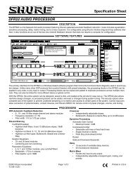
<strong>FreeSpace</strong> ® <strong>DXA</strong> <strong>2120</strong><strong>Digital</strong> <strong>Mixer</strong>/<strong>Amplifier</strong>Front and Rear Panel Diagrams561 LCD panel – Displays menu selections forconfiguring and viewing system settings.2 Directional buttons – Navigates system menusand setting options shown on the LCD.3 SELECT button – Confirms selections andsettings in the system menus.4 POWER LED – Blue light indicates the systemis on. No light when unit is off.5 SIGNAL and CLIP LEDs – Shows signal states forOUTPUT 1, OUTPUT 2, PAGE and DIRECT.Signal Unlit = No signalSignal Green = Signal present1 2 3 478Clip Unlit = No clippingClip Red = Clipping9106 GAIN knobs – Adjusts gain for OUTPUT 1,OUTPUT 2 and PAGE.7 BASS and TREBLE knobs – Adjusts tonalbalance for OUTPUT 1 and OUTPUT 2.8 Enclosure door – Conceals system controls.9 SIGNAL and CLIP LEDs – Shows signal states forInputs 1 – 4.Signal Unlit = No signalSignal Green = Signal presentClip Unlit = No clippingClip Red = Clipping10 Gain knobs – Adjusts gain for INPUT 1 – INPUT 4.TECHNICAL DATA SHEET1 3 2 4 5 6 8 7 9 10 1114 13 121 LINE INPUTS – Two unbalanced RCA audio jacksper input (summed to mono).2 MIC/LINE INPUTS – Balanced Euroblock inputjacks. One per input.3 MIC/LINE switch – Adjusts for the propersignal level being used with the four Euroblockinput connectors. (Mic connections require useof the Euroblock input jacks.)4 DIRECT INPUT – Balanced override input jack.5 PAGE INPUT – Balanced audio input jack.6 AUX OUTPUT – Fixed line-level signal output forother amplified equipment.7 OUTPUTS 1 and 2 – Speaker connections for twopowered outputs (70V, 100V or 4-ohm operation).8 REMOTE – Input jack for volume-only control andvolume control with A/B select user interfaces.9 BACKUP POWER – For connection to backuppower source.10 POWER OFF/ON – AC power switch.11 FUSE – T6.3AL/250V (100V and 120V) orT3.15AL/250V (220-240V).12 AC mains line cord jack – AC line voltage input.13 120V/220-240V switch – Switches between 120Vand 220-240V AC input voltage. This switch isnot provided on 100V AC input voltage models.14 COM – RS-232 serial port is reserved forsystem updates.3OF 8pro.<strong>Bose</strong>.com