Standards for Machinery Acceptance Testing and Balancing
Standards for Machinery Acceptance Testing and Balancing
Standards for Machinery Acceptance Testing and Balancing
- No tags were found...

You also want an ePaper? Increase the reach of your titles
YUMPU automatically turns print PDFs into web optimized ePapers that Google loves.
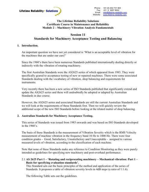
Phone:Fax:Email:Website:+61 (0) 402 731 563+61 (8) 9457 8642info@lifetime-reliability.comwww.lifetime-reliability.com1. Introduction.The Lifetime Reliability SolutionsCertificate Course in Maintenance <strong>and</strong> ReliabilityModule 2 – <strong>Machinery</strong> Vibration Analysis FundamentalsSession 11<strong>St<strong>and</strong>ards</strong> <strong>for</strong> <strong>Machinery</strong> <strong>Acceptance</strong> <strong>Testing</strong> <strong>and</strong> <strong>Balancing</strong>An important question we have not yet considered is „What is an acceptable level of vibration <strong>for</strong>the machines that are under our care?‟Since the 1960‟s there have been numerous <strong>St<strong>and</strong>ards</strong> published internationally dealing directly orindirectly with the vibration of rotating machinery.The first Australian <strong>St<strong>and</strong>ards</strong> were the AS2625 series of which appeared from 1983. They werespecifically geared to acceptance testing of new or repaired machines. There were some associated<strong>St<strong>and</strong>ards</strong> dealing with the vocabulary of vibration, shop balancing <strong>and</strong> requirements <strong>for</strong>instruments.Very recently there has been a new series of ISO <strong>St<strong>and</strong>ards</strong> published that significantly extend <strong>and</strong>update the AS2625 series <strong>and</strong> these will undoubtedly be adopted or adapted by Australian<strong>St<strong>and</strong>ards</strong> in due course.However, the AS2625 series <strong>and</strong> associated <strong>St<strong>and</strong>ards</strong> are still the current Australian <strong>St<strong>and</strong>ards</strong> <strong>and</strong>we will look at the requirements of these <strong>St<strong>and</strong>ards</strong> first. Then we will quickly review theadditional scope of the new ISO <strong>St<strong>and</strong>ards</strong> be<strong>for</strong>e looking at the related matter of shop balancing.2. Australian <strong>St<strong>and</strong>ards</strong> <strong>for</strong> <strong>Machinery</strong> <strong>Acceptance</strong> <strong>Testing</strong>.This series of <strong>St<strong>and</strong>ards</strong> was issued from 1983 onwards <strong>and</strong> was based on ISO <strong>St<strong>and</strong>ards</strong> developedin the 1960‟s.The basis of these <strong>St<strong>and</strong>ards</strong> is the measurement of Vibration Severity which is the RMS Velocitymeasurement of machine vibration in the frequency b<strong>and</strong> 10 Hz to 1000 Hz. There were fourcondition grades - Good, Satisfactory, Unsatisfactory <strong>and</strong> Unacceptable - assigned to variousmeasured levels of vibration, according to the classification of each machine.Note that none of these <strong>St<strong>and</strong>ards</strong> make any reference to Condition Monitoring as they were purelyintended as guidelines <strong>for</strong> specifying new machinery <strong>and</strong> post-overhaul per<strong>for</strong>mance.2.1 AS 2625 Part 1 – „Rotating <strong>and</strong> reciprocating machinery – Mechanical vibration: Part 1 –Basis <strong>for</strong> specifying evaluation st<strong>and</strong>ards‟.This St<strong>and</strong>ard sets out the basic principles of the method <strong>and</strong> application of the series of<strong>St<strong>and</strong>ards</strong>. It proposes a table of vibration severity levels in 4dB steps (a ratio of 1:1.6).The following Table sets out the guidelines.
Phone:Fax:Email:Website:+61 (0) 402 731 563+61 (8) 9457 8642info@lifetime-reliability.comwww.lifetime-reliability.comAS 2625 PART 1 SEVERITY GUIDELINESRange: 10 Hz to 200 Hz Shaft SpeedVibration B<strong>and</strong>width: 10 Hz to 1000 HzClass I Machines. Small machines to 15 kWClass II Machines. 15-75 kW on light foundations15-300 kW on heavy foundationsClass III Machines Above 300 kW on heavy <strong>and</strong> rigid foundationsClass IV Machines Above 300 kW on flexible foundations (soft mount)Classes V <strong>and</strong> VI not listedRANGES OF VIBRATION SEVERITY QUALITY JUDGEMENTSRMS Velocity (mm/s RMS) I II III IV0.280.45 A0.71 A1.12 B A1.80 B A2.80 C B4.50 C B7.10 C11.2 D C18.0 D28 D45 D2.2 AS 2625 Part 3 – 1983 “Measurement <strong>and</strong> evaluation of vibration severity of largemachines in situ”. For machines with power ratings more than 300 kW.Rigid Mounting Class III in Part 1.Flexible Mounting Class IV in Part 1.2.3 AS 2625 Part 4 – 1986 “Measurement <strong>and</strong> evaluation of vibration severity of smallrotating machines”. For machines with power ratings less than 300 kW.Machine classifications are determined firstly by speed, then mounting conditions <strong>and</strong> then bycoupling type. The resulting classification is then applied to the Part 1 table.SHAFT SPEED (RPM)LESS THAN 2000 GREATER THAN 2000MOUNTING DRIVE CATEGORY MOUNTING DRIVE CATEGORYRigid Rigid drive I Rigid Rigid drive IImountingmountingFlex drive II Flex drive III
Phone:Fax:Email:Website:+61 (0) 402 731 563+61 (8) 9457 8642info@lifetime-reliability.comwww.lifetime-reliability.comFlexiblemountingRigid drive II Flexible Rigid drive IIImountingFlex drive III Flex drive IV2.4 AS 1359 Part 114 – 1997 “Rotating electrical machines – General requirements. Part 114:Vibration measurements <strong>and</strong> limits”.This St<strong>and</strong>ard superseded AS 2625 Part 2 in 1997. It is much more comprehensive indescription <strong>and</strong> test requirements <strong>and</strong> includes proximity probe displacement allowances. Allnew motors sent out <strong>for</strong> re-work should be acceptance tested according to the requirements ofthis St<strong>and</strong>ard.Three grades are given – N (Normal) R (Reduced) <strong>and</strong> S (Special).The N grades are listed below.LIMITS OF VIBRATION SEVERITY VS SHAFT HEIGHT FOR 'N' GRADESPEED FREE SUSPENSION RIGIDMOUNTEDRPM 56-132 mm 132-225 mm 225-400 >400 >400600-3600 1.8 2.8 3.5 3.5 2.8The shaft height <strong>for</strong> an electrical machine is the vertical distance between the shaft centreline<strong>and</strong> the baseline of a typical foot-mounted frame <strong>for</strong> that machine.2.5 Other <strong>St<strong>and</strong>ards</strong>.Several other <strong>St<strong>and</strong>ards</strong> in this series are noted here.AS 2606 1983 “Vibration <strong>and</strong> shock – Vocabulary”. A useful glossary of terms.AS 2641 1983 “Vibration <strong>and</strong> shock – <strong>Balancing</strong> Vocabulary”.AS 2679 1984 “Requirements <strong>for</strong> instruments <strong>for</strong> measuring vibration severity”.3. New ISO <strong>St<strong>and</strong>ards</strong>.At the time of writing these notes there were five new ISO <strong>St<strong>and</strong>ards</strong> published under the generaltitle of “Mechanical vibration – Evaluation of machine vibration by measurement on nonrotatingparts”. A sixth St<strong>and</strong>ard is expected to be published shortly to complete the series. Weunderst<strong>and</strong> that it will deal with hydraulic pumps <strong>and</strong> motors.Some brief notes on each of these new <strong>St<strong>and</strong>ards</strong>.3.1 ISO 10816-1:1995(E). Part 1: General Guidelines.This is comparable to AS 2625 Part 1 in that it sets out the ground rules <strong>for</strong> the series.Significant differences are as follows.
Phone:Fax:Email:Website:+61 (0) 402 731 563+61 (8) 9457 8642info@lifetime-reliability.comwww.lifetime-reliability.comIt includes specific reference to the use of these guidelines <strong>for</strong> „operating conditionmonitoring‟ as well as acceptance testing.The frequency range is no longer restricted to the 10 to 1000 Hz b<strong>and</strong>.Reference is made to high frequency acceleration measurements required <strong>for</strong> bearingcondition monitoring <strong>and</strong> an in<strong>for</strong>mative Annex is given on this subject.Provision is made <strong>for</strong> measurements in displacement, velocity <strong>and</strong> acceleration.Diagrams are provided showing suggested measurement locations <strong>for</strong> horizontal <strong>and</strong>vertical electrically driven machines <strong>and</strong> also reciprocating machines.Reference to the required instrumentation to provide acceptable measurements of broadb<strong>and</strong>vibration.Two Evaluation Criteria are proposed: one to consider the magnitude of the measuredvibration; the other considers changes in magnitude (ie, <strong>for</strong> condition monitoring purposes).The <strong>for</strong>mer wordy descriptions <strong>for</strong> machine evaluation (Good, Satisfactory, etc) arereplaced by four Zones, A, B, C <strong>and</strong> D. The determination of these zones is quite flexibleeven though the suggested values in Annex B <strong>for</strong> Velocity are exactly the same as <strong>for</strong> AS2625 Part 1.Guidelines <strong>for</strong> seismically measured Displacement <strong>and</strong> Acceleration are also given.Guidelines are also proposed <strong>for</strong> the setting of Alarms <strong>and</strong> Trips.In summary, this St<strong>and</strong>ard represents a much more „real world‟ approach to the business ofmachinery acceptance testing. One hopes that it will be adopted by Australian <strong>St<strong>and</strong>ards</strong> in thenear future.3.2 ISO 10816-2: 1996(E). Part 2: Large l<strong>and</strong>-based steam turbine generator sets in excess of50 MW.This St<strong>and</strong>ard applies the principles set out in Part 1 <strong>and</strong> suggest vibration velocity zoneboundaries <strong>for</strong> two different speed ranges. Unlike AS 2625 Part 3 there is no considerationgiven to mounting considerations.3.3 ISO 10816-3: 1998(E). Part 3: Industrial machines with nominal power above 15 kW <strong>and</strong>nominal speeds between 120 r/min <strong>and</strong> 15 000 r/min when measured in situ.This St<strong>and</strong>ard covers a very wide range of machines <strong>and</strong> is complex to apply. It isrecommended that engineers with responsibilities in this area should become acquainted withthis St<strong>and</strong>ard.The proposed Evaluation zone boundaries are tabulated <strong>for</strong> four different groupings ofmachines <strong>and</strong>, interestingly, the velocity values do not necessarily follow the numbers used inPart 1. Values are given <strong>for</strong> RMS Velocity (the preferred parameter) <strong>and</strong> also <strong>for</strong> RMSDisplacement values.3.4 ISO 10816-4:1998(E). Part 4: Gas turbine driven sets excluding aircraft derivatives.This is a new St<strong>and</strong>ard without a precedent in the AS 2625 series. RMS velocity values aregiven <strong>for</strong> a wide range of turbine speed ranges.
Phone:Fax:Email:Website:+61 (0) 402 731 563+61 (8) 9457 8642info@lifetime-reliability.comwww.lifetime-reliability.com3.5 ISO 10816-6: 1995(E). Part 6: Reciprocating machines with power ratings above 100 kW.This again is a new St<strong>and</strong>ard <strong>and</strong> ,while it is relatively short, it is fairly complex in itsapplication.Limiting values are proposed <strong>for</strong> Displacement, Velocity <strong>and</strong> Acceleration <strong>and</strong> seven differentEvaluation Zones listed.Forms <strong>for</strong> data collection are suggested to assist with the process of collection <strong>and</strong> evaluation ofdata. A vibration severity grade nomogram is also supplied.The experience of the writer suggests that the condition <strong>and</strong> reliability of reciprocating enginesis poorly defined by vibration measurements alone <strong>and</strong> this St<strong>and</strong>ard seems to be a bit „overthe-top‟<strong>for</strong> either acceptance testing or condition monitoring purposes.4. Mechanical <strong>Balancing</strong> (Workshop <strong>Balancing</strong>).Mechanical <strong>Balancing</strong> (also called Workshop <strong>Balancing</strong>) is not to be confused with In-Situ<strong>Balancing</strong> which is a distinctly different technique.There is often confusion <strong>and</strong> uncertainty in industry as to how the quality of „shop balancing‟ canbe related to the measured vibration of the rotor in the machine after balancing, <strong>and</strong> hence to the AS2625 guidelines.The short answer is that the two (generally speaking) cannot be directly related. However, athorough underst<strong>and</strong>ing of the principles of shop balancing will assist to provide a result that willbe more than satisfactory.4.1 Mechanical <strong>Balancing</strong> St<strong>and</strong>ard.AS 3709-1989 „Vibration <strong>and</strong> shock – Balance quality of rotating rigid bodies‟ is therelevant St<strong>and</strong>ard. Every machinery engineer must have access to a copy of this St<strong>and</strong>ard.On the following pages we reproduce the key evaluation tables from the St<strong>and</strong>ard.It is important to note that this St<strong>and</strong>ard is taken from an ISO St<strong>and</strong>ard that had its origins in the1960‟s. There<strong>for</strong>e the „General Examples‟ tabulated there <strong>for</strong> Rotor Types represent thereasonable target eccentricities <strong>for</strong> the technology of those days.With modern balancing machines <strong>and</strong> a precision approach to rotor assembly it is possible toaim <strong>for</strong> at least one - <strong>and</strong> preferably two – grade improvements compared to what is tabled.For example, it is quite possible to balance a quality pump rotor to G1 whereas the <strong>St<strong>and</strong>ards</strong>uggests G6.3 <strong>for</strong> this type of component.
Phone:Fax:Email:Website:+61 (0) 402 731 563+61 (8) 9457 8642info@lifetime-reliability.comwww.lifetime-reliability.comHowever, working to these tolerances dem<strong>and</strong>s a much greater appreciation of fits <strong>and</strong>tolerances in machining <strong>and</strong> the assignment of keyway masses <strong>and</strong> the like.4.2 The <strong>Balancing</strong> Process.In the balancing shop the rotor is supported on its bearing journals in a pair of pedestals <strong>and</strong>driven at a speed which may well be a lot less than its service speed.There are two different kinds of balancing machines:a) Soft Bearing Machine. The rotor is supported in a suspension „swing‟ assembly <strong>and</strong> thenatural frequency of the supported assembly is typically very low. There<strong>for</strong>e the rotor turnsabout its centre of mass <strong>and</strong> the eccentricity is measured directly by vibration probesattached to the swing assembly.b) Hard Bearing Machine. The rotor is supported in trunnion assemblies that are rigidlymounted. There<strong>for</strong>e the rotor is <strong>for</strong>ced to run within its geometric centre <strong>and</strong> the <strong>for</strong>ceresponse is measured at the pedestals.Both types of machines are capable of good results although the writer considers that the softbearing machine has accuracy advantages <strong>for</strong> large, slow-moving rotors. These types ofmachines can also be taken to sites <strong>and</strong> used without special foundations as are required <strong>for</strong>hard bearing machines.Regardless of the machine type the operator will run the rotor at a relatively slow speed <strong>and</strong>increase the speed with each improvement to balance until he is running the rotor as fast aseither available driving power or safety dictates. Material will either be added to the rotor orremoved according to the situation.When the balance is completed to the required tolerance the operator will usually conduct aresidual balance check as required in the St<strong>and</strong>ard <strong>and</strong> prepare a Balance Quality Certificate <strong>for</strong>the client.4.3 Required In<strong>for</strong>mation.It is essential that the following in<strong>for</strong>mation is supplied in writing to the balancing shop whenthe Order is raised <strong>for</strong> the balancing job.The service speed of the rotor.The balance grade required.Where mass corrections are to be applied.Material <strong>for</strong> welding purposesThe location of the bearing journals <strong>for</strong> mounting the shaft in the balancing machine.(Mark with tape).The balancing machine operator will use the first two items of in<strong>for</strong>mation to determine themaximum residual eccentricity or unbalance allowable.