The Keystone Modeler, No. 80, Spring 2012, PRRT&HS
The Keystone Modeler, No. 80, Spring 2012, PRRT&HS
The Keystone Modeler, No. 80, Spring 2012, PRRT&HS
- No tags were found...

You also want an ePaper? Increase the reach of your titles
YUMPU automatically turns print PDFs into web optimized ePapers that Google loves.
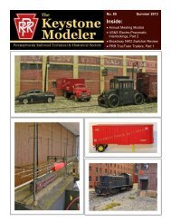
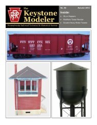
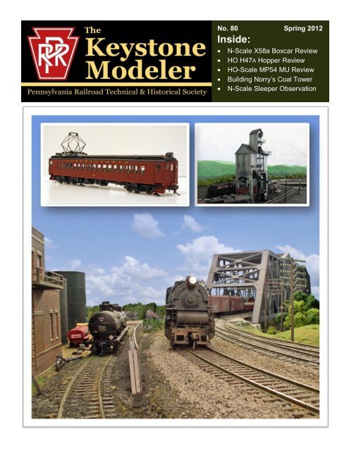
<strong>No</strong>. <strong>80</strong> <strong>Spring</strong> <strong>2012</strong>Inside:• N-Scale X58a Boxcar Review• HO H47A Hopper Review• HO-Scale MP54 MU Review• Building <strong>No</strong>rry’s Coal Tower• N-Scale Sleeper Observation
PRR I1sa 2-10-0 Decapod Steam Locomotive – HO ScaleFUNARO & CAMERLENGOhttp://www.fandckits.com/PRR X26 USRA Boxcar – HO Scale(BLI Photo)As if the H10 and K4 were not enough, BLI has also announcedanother run of its I1SA in its Paragon 2 line.Equipped for sound, DC, and DCC, there will be originalheadlight and modern headlight versions, and both will beavailable with either the original 90F82 short tender or the210F82A long tender. <strong>The</strong> model is due in October <strong>2012</strong>.CONCEPT MODELShttp://www.con-sys.com/PRR Queen Mary FD2 Flat Car – HO ScalePRR FW1 Well Flat Car – HO Scale(F&C photo)F&C has available a resin kit modeling the USRA singlesheathed wood sided boxcar which the PRR classed as X26.<strong>The</strong> kit models the car as it was modified and upgraded, servingthrough the 50's. Three versions are available withYoungstown (shown), spliced Youngstown, Creco, andspliced Car Builders doors.PRR G28 Gondola – HO Scale(F&C photo)F&C has also made available a resin kit modeling the G28class of steel 52'6” gondola. <strong>The</strong>re have been articles on <strong>The</strong>G28 class in TKM. See <strong>No</strong>. 53, December 2007, and <strong>No</strong>. 57,April 2008.FD2 Flat Car (Concept Models photo)MOUNT VERNON SHOPShttp://www.mountvernonshops.com/PRR (and a few others) Decals-HO ScaleFW1 Flat Car (Concept Models photo)Concept Models has available at their website resin kits ofthese two unique heavy duty flat cars. Additional models arein development.PRR GS and GSH (TKM Photo)John Frantz's Mount Vernon Shops has become a prolificprovider of high quality decals for use on (mostly) PRR freightcars. His latest offerings are decals for the GS and GSH classgondolas. In HO, GS gons are available from Bowser, F&C,and Sunshine, and the GSH class is available from F&C and<strong>The</strong> <strong>Keystone</strong> <strong>Modeler</strong> 5 <strong>No</strong>. <strong>80</strong>, <strong>Spring</strong> <strong>2012</strong>
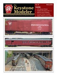
Product Review – Eastern Seaboard ModelsCorporation N-Scale PRR Class X58A BoxcarBy Al Buchan(Bob Buchan photo.)THE PROTOTYPE<strong>The</strong> PRR had a fleet of 432 class X58A boxcars as of October23, 1967. In addition to the subclass “A,” the PRR also rosteredX58, X58B and X58C cars. <strong>The</strong> X58 series cars were verydistinctive in that they were the Pennsy’s only all steel outsidebraced boxcars, except for the late 1940’s class X36 – one of akind PRR 103500. <strong>The</strong>se cars were turned out at Sam ReaShops in 1965 and were all contained with the series 112000 to118490. <strong>The</strong>y were AAR Mechanical Class RBL (insulatedbunkerless refrigerator car with load restraining devices),while the subclasses were all AAR Mechanical Class XM, XLor XP boxcars.THE MODEL<strong>The</strong> specific model reviewed is ESM’s stock number222105, PRR 113709, with roofwalk, high ladders and brakewheel and Hydro-Cushion underframe. <strong>The</strong>se RTR modelsare made and assembled in China, the trucks are made inChina by BLMA while the body mounted couplers are madein the US by Micro-Trains ® Line. It is recommended for use oncurves of more than 10-inch and greater radius. This specificcar was placed in service in March 1965 (according to thestenciling, the box says April 1965) and paint and lettering isbased on a March 1968 photograph. Looking at it right out ofthe box was a wow for me, as I haven’t really looked at N-scale equipment in quite some time.<strong>The</strong> X58A PRR 113709 is AAR Mechanical Designation XP,AAR Car Type Code A220. It falls in a series of 200 similarcars numbered 113687 to 113886. <strong>The</strong> load restraining deviceon this car is specified as “DFB.”<strong>The</strong> FCC looks to me to be right on for the period and thelettering is exquisite, neatly wrapping around the outsidebraces and the correct colors (white and yellow). I could readit all, even the trust data, of course with a magnifying glass.<strong>The</strong> only lettering flaws I could see were the lube data being“LUB SRS 11-16-65 PRR,” and the paint data on the end of thecar “PAINT SRS 11-65.” At least this is what I saw through themagnifying glass.<strong>The</strong> lube data indicating it was last serviced at Sam ReaShops on <strong>No</strong>vember 16, 1965, and the paint data indicatingpainting in <strong>No</strong>vember when the car was out shopped inMarch is problematic. It certainly didn’t sit at SRS for eightmonths awaiting these services. However, this is rivet countingand certainly doesn’t detract one iota from the model. <strong>The</strong>car and cushioning housing are painted FCC, while the couplersand underside are black.<strong>The</strong> underside brake rigging and cushioning devices appearto be correct and even include piping about as fine as onecan get with plastic and still be durable. I was impressed. <strong>The</strong>roofwalks are see-through super-fine that puts some of myHO-scale models to shame. <strong>The</strong> overall dimensions check outwell.This model is a definite keeper. By the time you read thissome lucky N-scaler will have picked this up at the annualmeeting raffle. If you’re modeling this time period I recommendgetting one and get a LV one also as they were a productof SRS and found their way in many PRR manifestfreights. It comes in the variations listed – As-Built body –with roofwalk, high brake gear, high ladders; Transitionalbody – no roofwalk, high brake gear, low ladders except forthe A end; Transitional body variant – no roofwalk, highbrake gear, high ladders; Modern – no roofwalk, loweredbrake gear, low ladders; and Hydra-Cushion or <strong>Keystone</strong>cushioned underframe.<strong>The</strong> <strong>Keystone</strong> <strong>Modeler</strong> 7 <strong>No</strong>. <strong>80</strong>, <strong>Spring</strong> <strong>2012</strong>
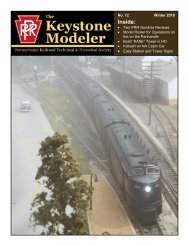
Product Review – ExactRail Platinum SeriesHO-Scale PRR Class H47A Covered HopperBy Al Buchan(Bob Buchan photo.)THE PROTOTYPEAs of October 23, 1967, the PRR had a fleet of 50 classH47A covered hoppers in series 260656 to 260705. In additionto the subclass “A,” there were also 100 plain H47 cars in series260871 to 260910. <strong>The</strong> X47 series cars were distinctive inthat they were the Pennsy’s only non-painted all aluminumcars (with steel underframes).<strong>The</strong>se 4750 cu. ft. cars were turned out by Magor RailcarDivision of Fruehauf Corp. in 1965. <strong>The</strong> X47 and 47A wereAAR Mechanical Designation LO and AAR Car Type CodeL052. <strong>The</strong> H47 and H47A had the same dimensions and it isnot understood why there were two different classes. <strong>The</strong>rewere no footnotes in the ORER to provide clues as to the differences.THE MODEL<strong>The</strong> specific models reviewed are ExactRail’s stock numberEP-81004-4, PRR 260683 and EP-81004-3, PRR 260672,with trough hatches, roofwalk, high ladders and brakewheel, separate air line across bottom chord, cut levers, airhoses and individual drop grab ladders. <strong>The</strong>se ready-to-runmodels are designed and tooled in the USA and made inChina. <strong>The</strong>se specific cars were placed in service in December1965 Looking at it right out of the box this appears to be anexcellent model.<strong>The</strong> car body color is aluminum with exquisite crispblack lettering. I could read it all without a magnifying glass.<strong>The</strong> lettering matches exactly that in the prototype photo.<strong>The</strong> A-end brake rigging appears to be correct and even includesfine piping. I was impressed. <strong>The</strong> roofwalks are superfinesee-through aluminum. I think I would give the car anovercoat of clear dull, as raw aluminum didn’t have toomuch of a sheen.<strong>The</strong> overall dimensions check out very well. This modelis a definite keeper.By the time you read this two lucky HO-scalers will havepicked them up at the annual meeting raffle. If you’re modelingthis time period I recommend getting one. Dependingon the industries served perhaps even two.<strong>The</strong> <strong>Keystone</strong> <strong>Modeler</strong> 8 <strong>No</strong>. <strong>80</strong>, <strong>Spring</strong> <strong>2012</strong>
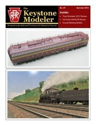
Product Review – Con-Cor’s MP54 MU CarsBy Tim Garner – Photos by the author unless notedCon-Cor’s new MP54 MU cars are impressive in looks and operation.Congestion on the commuter lines radiating from Philadelphia,exacerbated by the extra movements to turn and servicesteam engines, led the PRR to electrify the Main Linefrom Broad Street Station to Paoli in 1915. <strong>The</strong> system of11,000 volt, single phase, 25 cycle A.C. power would be thefirst installation of what eventually spread over PRR’s easternmainlines. As part of the project, the Altoona shops rebuilthundreds of steam-era MP54 suburban cars to electric multiple-unitcoaches and trailers.<strong>The</strong> electrified commuter service ultimately expanded inthe Philadelphia area to reach Chestnut Hill, Fort Washington,West Chester, Wilmington, and Trenton. As electrificationreached its ultimate limits in the 1930’s, electrified commuterservice expanded to include Baltimore to Washington, thePrinceton Branch, and New York to Trenton, and New York toSouth Amboy among other routes.To meet this demand, the fleet of MU cars grew to include361 coaches and 43 unpowered trailers, plus combines, fullbaggage cars, and mail-baggage cars. All were 64 ft. 5¾ in.long. <strong>The</strong>ir classes are listed in the table at right.Beginning in 1950, PRR rebuilt 99 cars with new smoother-ridingequalized trucks, stainless steel window frames, andupdated interiors. Only these MP54 cars survived into thePenn Central years as growing numbers of stainless steelBudd cars took replaced them.<strong>The</strong> Long Island operated the first electrified MP54 carsbeginning in 1908. <strong>The</strong>y operated on 650 volts of D.C. currentfed through a third rail. Ultimately, LI received 626 poweredcoaches, 15 baggage cars, 52 coach-baggage, and 230 unpoweredtrailers.PRR MP54 MU CARSType Classes DescriptionCoach MP54E1, MP54E2 72 seats, 1 restroomCoach MP54E3 Additional horsepower topull unpowered trailer, 72seats, 1 restroomModernizedCoachMP54E5 , MP54E6 72 seats, 1 restroom, 99carsCoach-Trailer MP54T 72 seats, 1 restroom, 43carsPassenger-Baggage52 seats, 1 restroom, 17 ft.8 15 /16 in. baggage compartmentPassenger-BaggageBaggageBaggage-MailMPB54E1,MPB54E5MPB54BE2,MPB54BE3MB62E1, MB62E2MBM62E1,MBM62E240 seats, 1 restroom, 26 ft.2 15 /16 in. baggage compartment20 ft. mail apartment<strong>The</strong> <strong>Keystone</strong> <strong>Modeler</strong> 9 <strong>No</strong>. <strong>80</strong>, <strong>Spring</strong> <strong>2012</strong>
Opposite sides of the powered coach. Based on the exterior details, this appears to be a model of the MP54E2.THE CON-COR MODEL<strong>The</strong> models are impressive right out of the box and totallycapture look and personality of the prototype. <strong>The</strong> coachesappear to be a spot-on match to the MP54E2. I did not ordercopies of the trailer, combine, or baggage-mail versions becauseof their relative prototype rarity, but photos of the modelson Con-Cor’s web site suggest they are just as impressive.Con-Cor did not model the baggage-only cars.EXTERIOR DETAILS<strong>The</strong> models feature a host of separately applied parts includinggrab irons, safety chains, windshield wipers, brakeand signal hoses, MU receptacles, air whistles, and roof details.One surprise is that the underside of the trap doors overeach set of steps includes a rarely modeled handrail neededby boarding passengers when the trap is open.<strong>The</strong> spring-loaded pantograph is an entirely new modeldesigned to match those on the MP54 right down to the singlepick-up shoe, air cylinders, and two-level base. <strong>The</strong> underbodyis fully detailed.On the MP54E2, the power truck below the pantograph isequipped with roller bearings. <strong>The</strong> unpowered truck at theopposite end is a different design with friction bearings. <strong>The</strong>model duplicates this detail. Trucks also have pilots on eachend. <strong>The</strong> cars are equipped with brown plastic magnetic couplerswith coil springs. I plan to replace mine with shortshankscale metal couplers.INTERIOR DETAILSEach coach includes an interior molded in tan styrene.<strong>The</strong> coach seats, lavatory, and bulkheads are modeled. Toprovide room for weight and the motor, the seats bottoms arenot full height. This is not noticeable through the windows.ELECTRICAL AND OPERATION<strong>The</strong> powered car is wired for straight DC operation, but itis DCC ready. Carefully snap off the center of the clerestoryroof and you will expose a printed circuit board. On top ofthe board is a socket for a wire coming from the pantograph.<strong>The</strong>re are two micro slide switches. One turns off the headlightsfor mid-train cars and the other activates power collectionfrom the pantograph. <strong>The</strong> LED headlights are on the topof the board and the LED interior lights are on the bottom. Ason Con-Cor’s earlier suburban MP54 cars, all the lights areamber which makes the effect too orange for my taste – myonly criticism of these cars.<strong>The</strong> <strong>Keystone</strong> <strong>Modeler</strong> 10 <strong>No</strong>. <strong>80</strong>, <strong>Spring</strong> <strong>2012</strong>
▲ Opposite ends of the powered car. <strong>The</strong> level of detail is amazing. <strong>No</strong>te the marker lights, windshield wipers, air whistle, chains, grab irons, cut levers, MUreceptacles, hoses, and door latches. ▼<strong>The</strong> pantograph details are exceptionally accurate.<strong>The</strong> <strong>Keystone</strong> <strong>Modeler</strong> 11 <strong>No</strong>. <strong>80</strong>, <strong>Spring</strong> <strong>2012</strong>
Remove the roof to access the circuit board. Slip it off the four tallpins and turn it over to access the 8-pin DCC socket. <strong>The</strong> ovalshaped hole accommodates a speaker for Con-Cor’s sound decoder(available separately), which includes authentic sounds for PRR andLong Island MU cars, including WABCO Trombone Whistle sounds.Two traction tires give the powered car significant pulling power.<strong>The</strong> bulge in the center of the floor that looks like a water tankhouses the motor.<strong>The</strong> <strong>Keystone</strong> <strong>Modeler</strong> 12 <strong>No</strong>. <strong>80</strong>, <strong>Spring</strong> <strong>2012</strong>
<strong>The</strong> circuit board is supported on four metal pins comingup from the floor. You can carefully lift the board off the pins(a press fit into four sockets) and turn it over to expose the 8-socket DCC plug. Any decoder with an 8-pin plug will fit.Con-Cor offers a sound decoder and speaker for the MP54. Ahole for the speaker is provided in the circuit board and holesin the floor allow the sound to escape.<strong>The</strong> circuit board in non-powered cars is similar exceptthere is no provision for a decoder. <strong>The</strong>re are micro slideswitches for headlights and pantograph power selection.<strong>The</strong> powered car is driven by a small-diameter doubleendedmotor contained in a cavity in the underbody at thecenter of the car. Drive shafts power all four axles on the car.This amazing piece of miniature engineering means the motoris not visible in the interior of the car and appears as a watertank in the center of the underbody. All eight wheels pick upcurrent on both the powered and unpowered cars.It also has surprising pulling power thanks to one tractiontire on each powered truck. I coupled three unpowered MP54and six of Con-Cor’s MP54 suburban coaches to a poweredunit and it pulled the entire train up a 2% grade without slipping.Most photos of MU trains I’ve seen are six cars or less,so you could easily get by with one powered car per train.ADDING DETAILSince the car interiors are lighted, I would recommendpainting the interiors and adding figures to the seats. Becausethe seats are not full height, you’ll need to cut off the legs ofseated figures before you cement them in place so they appearproper height through the windows. You should also cementa standing figure as an engineman behind the right front portalof your lead car. Adjust the height of his legs until his faceappears in the center of the portal window.Light weathering of the underbody and roof would beappropriate. I typically use Floquil Railroad Tie Brown on underbodies,trucks, and wheels to suggest railroad grunge witha hint of rust.Overall, Con-Cor did an excellent job with these models.As a result, I would not be surprised if the price of Alco Modelsbrass MP54s takes a nosedive on eBay.▲ <strong>The</strong> micro slide switches for the pantograph andthe headlights are visible on the circuit board for theunpowered car. <strong>The</strong> interior lights remain on whenthe headlight switch is turned off. <strong>The</strong>re is no provisionfor a decoder in non-powered cars.► <strong>The</strong> underbody of the unpowered car is slightly differentsince no accommodation for the motor is necessary.All eight wheels pick up power for the carlighting.<strong>The</strong> <strong>Keystone</strong> <strong>Modeler</strong> 13 <strong>No</strong>. <strong>80</strong>, <strong>Spring</strong> <strong>2012</strong>
▲ Even without catenary, these cars make a great looking train. ▼<strong>The</strong> red-orange glow of theamber LEDs is my only issue on these exceptional models.Paint Schemes• PRR unlettered – post war Tuscan sides, black roof• PRR Pre War – light Tuscan, boxcar red roof, olivetrucks• PRR Post War – dark Tuscan sides, black roof• PRR 1960’s – dark Tuscan, large keystones• Long Island Tuscan – dark Tuscan sides, black roof• Long Island Gray – Tichy gray, white, white letteringPRR cars available• Powered Coach• Powered Combine• Powered Baggage-Mail• <strong>No</strong>n-Powered Coach• <strong>No</strong>n-Powered Combine• <strong>No</strong>n-Powered Baggage-Mail• <strong>No</strong>n-Powered Trailer Coach<strong>No</strong>tes: All cars include a pantograph except the trailercoach. <strong>The</strong> combine matches class MPB54E1.Long Island cars available• Powered Coach• Powered Combine• Powered Baggage-Mail• <strong>No</strong>n-Powered Coach• <strong>No</strong>n-Powered Combine• <strong>No</strong>n-Powered Baggage-Mail<strong>No</strong>tes: Cars include dummy third rail shoes.Decoders• Sound plug-in decoder with speaker and housing• <strong>No</strong>n-sound plug-in decoder<strong>The</strong> <strong>Keystone</strong> <strong>Modeler</strong> 14 <strong>No</strong>. <strong>80</strong>, <strong>Spring</strong> <strong>2012</strong>
Scratchbuilding the <strong>No</strong>rthumberlandConcrete Coaling TowerBy Chuck Cover<strong>The</strong> <strong>No</strong>rthumberland engine facilitywas located midway in the yard. <strong>The</strong> concretetower was constructed as a replacementfor the large timber coaling trestlebuilt when the yard was first opened in1911. It was very similar in design, withrecessed panels on the ends, to the largerconcrete coaling towers built in Renovo in1941 and Southport in 1942 as the Pennsyupgraded its facilities to handle WW IItraffic. <strong>The</strong>se towers provided both coaland sand.<strong>The</strong> “<strong>No</strong>rry” coaling tower had a deliverytrack running through the center betweenthe six legs where hopper carscould dump their loads through grates intoa pit beneath the slightly elevated tracksiding below the tower. A skip hoistbucket on vertical tracks with a pulleymechanism, which looks similar to a Fairbanks-Morsedesign, picked up loads ofcoal from the pit and moved the coal tothe top of the tower. <strong>The</strong> lift mechanismwas located on the outside of the <strong>No</strong>rrytower, but sat in a recess on the largertowers in Renovo and Southport. Afternumerous trips up the lift mechanism, thetower would be filled and ready to servicethe locos.<strong>The</strong> <strong>No</strong>rry tower could service locomotiveson two tracks, one on each side ofthe tower. On the side of the tower withthe skip hoist, the service track was fartheraway from the tower than the other sideso that the locomotives could clear thehoist mechanism. <strong>The</strong> coal chute on thatside of the tower was elongated to accommodatethat longer distance. Bothcoaling chutes were located on the sameend of the tower. When looking at thehoist side of the structure, the coal chuteswere on the left. On the other side of thestructure the coal chutes were on the right. At the other endof the sides from the chutes were pipes to provide dried sandto the locos. <strong>The</strong> <strong>No</strong>rry tower also had two recessed panels oneach end of the structure. It was a poured concrete structure,<strong>The</strong> finished coaling tower on my layout.which was constructed by building a wooden frame and thenpouring the concrete into the form. When the form was removedthe outline of the boards remained which is a distinctivecharacteristic of this structure.<strong>The</strong> <strong>Keystone</strong> <strong>Modeler</strong> 15 <strong>No</strong>. <strong>80</strong>, <strong>Spring</strong> <strong>2012</strong>
<strong>The</strong> prototype in the 1970’s after the end of steam. (Dom Walker photo.)<strong>The</strong> <strong>Keystone</strong> <strong>Modeler</strong> 16 <strong>No</strong>. <strong>80</strong>, <strong>Spring</strong> <strong>2012</strong>
More 1970’s images of the tower (clockwise from upper left): door and window end; opposite end; non-hoist side; hoist side detail; hoist side detail.(All photos, Tom Hayden.) <strong>No</strong>te that Pennsylvania Railroad Facilities in Color, Volume 7, <strong>No</strong>rthern Division by Robert Yanosey has a photo of the <strong>No</strong>rry coalingstation on July 10, 1955 on page 28.<strong>The</strong> <strong>Keystone</strong> <strong>Modeler</strong> 17 <strong>No</strong>. <strong>80</strong>, <strong>Spring</strong> <strong>2012</strong>
MAIN STRUCTUREDrawings 1 and 2 (previous page) are provided ofthe various portions of the main structure to help withconstruction. Use Evergreen Scale Models (ESM) #255,5/16 in. square tube as the main structural supports. Cutsix to a length of 50 ft. for the legs. <strong>The</strong>n cut four to alength of 17 ft. for the ends and eight to a length of 11 ft.3 in. for the sides, as the horizontal supports for thestructure. Using solvent-type plastic cement, assemblethe hoist side with two 11 ft. 3 in. horizontal supportseven with the top of each leg and the other two at 28 ft.Assemble the non-hoist side the same way but with thelower horizontal supports at 21 ft. When the side supportsare dry attach the two sides together using the endhorizontal supports positioned at the top of each leg andthe at 25 ft. Make sure the structure is square.Use ESM #9040 0.040 in. sheet styrene for the outsideof the structure. Cut a sheet of the styrene to sizeusing the drawing. <strong>The</strong>n cut out the legs and recessedpanels as well as any door or window openings (Tichy#<strong>80</strong>46, nine-pane masonry window and Tichy #8130,Residential door with transom). Also cut out sheet styrenefor the four recessed panels. <strong>The</strong>se must be slightlylarger than the actual openings to allow for a gluing surface.To simulate the poured concrete board lines, scribeeach wall piece with a scalpel blade. I chose to make thelines 9 scale inches apart. This was chosen after tryingto determine what size lumber the Pennsy would use. Itried counting the board marks from the photos andcomparing that to the overall dimensions, then estimatingthe width. I also had to consider the ease of themodeling process. I decided on 9 scale inch boards anddrew horizontal lines 9 in. apart and scribed the sheetstyrene (see photo). When the four main structure sidesare complete, glue them to the super structure trying tomatch the scribed lines at the corners.Glue ESM #8608 (.066 in. x .090 in.) strip styrene around three of the inside edges ofthe two ends of the tower where openings for the recessed panels have been cut. <strong>The</strong>seprovide gluing surfaces for the recessed panels. <strong>The</strong> square tube leg will serve as thefourth side. <strong>The</strong>n glue the scribed recessed panels in place. All the other visible surfacesincluding the back and sides of the legs must now be covered with the scribed styrene(see photo). Lay out the measurements on a sheet of 0.040 in. sheet styrene (see photo)and scribe the lines then cut out the various pieces to size. Glue everything in place tryingto match the scribed lines at each corner. Lightly sand the structure with fine gritsandpaper to remove the burrs from the scribing lines and to slightly round the corners.It is difficult to see in many of the photos, but at the base of the tower between thelegs is a concrete reinforcing wall. It appears to be flush with the legs on the deliverytrack side, inside of the tower, but it is not as wide as the legs. Use .0<strong>80</strong> in. sheet styrenecut so that it is 6 scale feet high and fits between the legs. I did not notice this detail untillate in the construction process so the wall sections were installed after I had positionedthe tower on the site. On my tower these reinforcing walls were not installed at the bottomof the legs but a bit higher to take into account that the legs were sitting in the holesthat were drilled to level the tower (see site preparation below).▲ <strong>No</strong>te 5 /16 in. square tubing is used to frame the superstructure. Scribed siding is attachedto the frame to simulate the surface of cast concrete.▲ Scribing the .040 in. styrene sheet.► Scribing the legs.<strong>The</strong> <strong>Keystone</strong> <strong>Modeler</strong> 19 <strong>No</strong>. <strong>80</strong>, <strong>Spring</strong> <strong>2012</strong>
Using Plastruct #91630, HO Asphalt Shingle, build the pitched roof forthe main structure. Cut the shingles sheet to size and use .04” sheet styreneto reinforce the roof and to maintain the correct pitch (see photo). Test fit theroof, but do not attach it at this time.<strong>The</strong> main structure, hoist side.A ¾ view of the door/window end and non-hoist side.HOIST TOWERUse the same .040 in. scribed sheet styrene to build the hoist house (seedrawing 3). <strong>The</strong> hoist house side is 8 ft. wide and 25 ft. high to the eaveswith a 6 ft. x 10 ft. opening cut into the bottom. Each end is 10 ft. wide x 25ft. high and the non-hoist side is 8 ft. wide x 25 ft. high with a door opening.<strong>The</strong> peak of the roof is 4 ft. higher than the eaves. Reinforce the corners withstrip styrene and glue together keeping the structure square. <strong>The</strong> roof isconstructed and reinforced with the same materials as the main structureroof. Do not attach the roof at this time.<strong>The</strong> hoist tower must be recessed into the main structure roof. <strong>The</strong> hoistside surface is even with the surface of the main structure and it extends inwardto the roof peak. Take the main structure roof and remove an 8 ft. widerectangle from the center of the hoist side so that the hoist tower will side intothe slot. I had to do quite a bit of fitting to get it to fit properly. I also removedabout 6 in. of the outside wall on the bottom of the hoist side of thehoist tower so that its wall and that of the main structure were flush (seeshaded area on drawing 3).At this point, I painted both reinforced roofs a flat black and both structuresa concrete color. I used a mix of artist’s acrylic paints, Neutral Gray,Parchment, Payne’s Gray and Burnt Sienna. Use a mix of Neutral Gray andParchment to obtain the aged concrete look. <strong>The</strong> Payne’s Gray was used as awash, diluted with water, to give the dark soot look and the Burnt Siennawill provide the rust color. Looking at the few photos taken in the late1950’s, the tower is very black with soot and smoke from all the steam power.Most of the photos that I have seen were taken well after the demise ofsteam and the tower has that old concrete look, almost a sandy color, withmost of the black being washed off by the rain and snow. I heavily weatheredmy tower to reflect heavy use in 1957. When satisfied with the weathering,lightly sand the sides with fine grit sandpaper which will give it a lessuniform look by taking some color from a few areas.Before final assembly, paint and install the doors and windows and put“glass” behind the windows. Start the final assembly by gluing the roof tothe main structure. <strong>The</strong>n fit the hoist house into the roof slot, and, makingsure that everything is square, glue it in place. Leave the attachment of thehoist house roof until the final assembly.PREPARE THE SITE<strong>The</strong> tower has a delivery track running through it to supply coal. <strong>The</strong>delivery track is slightly elevated, higher than the two service tracks locatedon each side of the tower. To raise the coal delivery track, cut a strip of 1 /8 in.Masonite ® fiberboard 1½ in. wide and to a length that will satisfy your spacerequirements. I used a 3 in. strip for the entry under the tower and an 8 in.strip for the rest of the siding. Between the two strips I cut out a rectangularhole 1½ in. wide for the grate x 3 in. toward the hoist side of the tower. I cutall the way through my ½ in. Homasote ® so that the pit is deep enough,about 5 /8 in., to accommodate the skip hoist track and bucket. <strong>The</strong> Tichycoaling tower lift mechanism (Tichy #<strong>80</strong>08) will be attached to the outside ofthe <strong>No</strong>rry coaling tower (described in the next section) and will protrudeabout and inch from the hoist side of the tower. <strong>The</strong> pit must be largeenough to accommodate the track and bucket of the lift mechanism.<strong>The</strong> <strong>Keystone</strong> <strong>Modeler</strong> 20 <strong>No</strong>. <strong>80</strong>, <strong>Spring</strong> <strong>2012</strong>
▲Roof assembly for main structure. ► Hoist house. ▼ Hoist house recessedin the main structure roof.Drill six ¾ in. holes for the legs. That way you will beable to fine tune where the tower, delivery and service trackswill be located and later fill in the holes with your scenerygoop and ground cover. Wait until the details are installedon the tower before you put in your service tracks.I did not have any photos of the grate or coal pit, so Ibuilt a nice looking grate following a design that I copiedfrom a Fine Scale Models kit, but I winged the rest. Unlessthe coaling tower will be right next to the edge of your layoutit will be hard to see the pit. Scratchbuild the pit structurewith I beams and the grate with strip styrene. Build a smallconcrete pad as a landing for the steps. <strong>The</strong> entire area waspainted flat black.In the prototype photos one can see a small concretestructure near where the stairway comes down to the ground.This is the power house for the coaling tower. I did not haveroom for this and did not model it.<strong>The</strong> <strong>Keystone</strong> <strong>Modeler</strong> 21 <strong>No</strong>. <strong>80</strong>, <strong>Spring</strong> <strong>2012</strong>
◄ Another view of hoist house added to main structure. ▲ Site preparation – pit and grate. ▼ Sitepreparation, cement pad, and final stairway.Details, nonhoistside.Details, ¾ view door/windowend and non-hoist side.<strong>The</strong> <strong>Keystone</strong> <strong>Modeler</strong> 22 <strong>No</strong>. <strong>80</strong>, <strong>Spring</strong> <strong>2012</strong>
Details, hoist side.Details, hoist side, bucket, and pit.Details, plain end.Details, ¾ view of plain end and non-hoist side.<strong>The</strong> <strong>Keystone</strong> <strong>Modeler</strong> 23 <strong>No</strong>. <strong>80</strong>, <strong>Spring</strong> <strong>2012</strong>
DETAILING THE COALING TOWER<strong>The</strong> next step is to detail the tower. Include as many detailparts as you think are appropriate for your tower. Mycoaling tower is about 2 feet from the edge of the layout so Ichose to attach details such as the lift mechanism, main steps,railings, ladders, platforms, coal chutes, sanding hoses andpulley/sheave apparatus. I did not go to the extent of puttingall of the cables on the tower or including some of the minorplatforms and other hardware. Use the prototype photos as areference.Most of the detail parts can be purchased from Tichy.Many were part of Don’s 400-ton Coaling Tower Kit #7010.Fortunately these parts can be purchase separately and instructionsare available on the web site:PARTSQty. Item.DescriptionTichy Train Group2 #<strong>80</strong>01 open grate platform and handrails5 #<strong>80</strong>02 safety cage ladder and staircase2 #<strong>80</strong>03 coal chutes1 #<strong>80</strong>08 coaling tower lift mechanism1 #<strong>80</strong>60 fire escape platformGrandt Line1 #5122 Cable Sheave, 43 in. diameterAll detail parts should be painted flat black while still onthe sprues. <strong>No</strong>te: All of these detail parts are very delicateand will easily come unglued or break (I know from experience).Handle the tower carefully as you apply the detailparts. Detail the tower in the sequence that is described andyou will have an easier time than I had. <strong>The</strong> hoist track extendsbelow the legs so detail the hoist side of the tower lastbecause you will not be able to stand the tower up on yourwork bench after the hoist lift mechanism is attached to thetower. I included many close-up construction photos of thedetails which I hope will help others with the detailing.Start by detailing the end of the tower that has the doorand window. Most of the detailing consists of stairways andladders with connecting platforms. Follow the Tichy directionsfor assembly and the photos of the tower to get everythinglocated properly. Leave the bottom course of steps untillater for ease of handling. <strong>The</strong> opposite end of the tower hasno details.Detail the non-hoist side of the tower next. Again thereare steps, platforms, and ladders as well as a coal chute toserve locomotives on that side of the tower. Use photos toapply the details.For the hoist side of the tower, the lift mechanism was assembledas described in the Tichy instructions. It is very delicate.<strong>The</strong> hoist mechanism track should extend down into thecoal pit below ground level. <strong>The</strong> top of the hoist track curvestoward the building and should enter the opening in the hoisthouse to dump loads into the storage bins. <strong>The</strong> Tichy liftmechanism is too long, so remove about 3 in. from the curvedupper section so that it can be correctly positioned. Cementthe lift mechanism to the hoist side of the tower following thephotos as a guide. Finish the lift mechanism by installing thecounter weights and the bucket.Since the lift mechanism is attached to the side of the tower,the coal chute on this side must extend farther away fromthe tower than on the non-hoist side. Build a rectangular tubeextension from the side of the tower out of .060 in. sheet styreneand attach the Tichy coal chute to the extension. Makethe extension long enough to reach the service track whichmust clear the hoist lift mechanism. I also built the supportingstructure with two pulleys that extend above this coalchute, which caught my eye in the photos. Use appropriatesize ESM strip styrene angles, and build the supporting structure.Attach the Tichy pulleys to the top. <strong>The</strong> large pulley atthe top of the hoist house is the Grandt Line 43” cable sheavewhich was glued to two ESM strip styrene angles. I modeledthe cable that extends from the hoist bucket to that largesheave and the cable that extends from the counter weights tosome pulleys.<strong>The</strong> tower is now ready to place on the prepared site. Besure you have proper clearance for all of your locomotives. Ihad to move the hoist side service track away from the towera bit to assure clearance for my I1 locomotives.I only found one good photo from the 1950’s of the sandlines that ran from the two sides of the tower. It shows astraight pipe that ran from the tower to a support post on thefar side of the service track. It appears that a flexible hose wasattached to the pipe and the workers could access that hosefrom the locomotive. Use 22 gauge solid wire for the sandlines. With a scalpel blade slice the insulation and expose thecopper wire to simulate the solid pipe. Pull down the insulation,see photo, to simulate the flexible hose. Place a supportangle into the ground and ACC the copper wire to it. Painteverything flat black.<strong>The</strong> <strong>Keystone</strong> <strong>Modeler</strong> 24 <strong>No</strong>. <strong>80</strong>, <strong>Spring</strong> <strong>2012</strong>
Details, ¾ view of plain end and hoist side.Above two photos show opposite ¾ views of hoist house.Finished tower on the layoutshowing the plain end andhoist.<strong>The</strong> <strong>Keystone</strong> <strong>Modeler</strong> 25 <strong>No</strong>. <strong>80</strong>, <strong>Spring</strong> <strong>2012</strong>
<strong>The</strong> finished model on the layout, hoist side.<strong>The</strong> <strong>Keystone</strong> <strong>Modeler</strong> 26 <strong>No</strong>. <strong>80</strong>, <strong>Spring</strong> <strong>2012</strong>
Modeling an N-Scale Heavyweight-Era Blue Ribbon TrainPart 3: Plan 2413A 5-CompartmentSleeper Observation CarsBy Claus Schlund – Images by the author▲ <strong>The</strong> 5-compartment sleeper-observation Parkesburg awaiting assignment.INTRODUCTIONAs with many other areas of its operation, the PRR marchedto the beat of its own drum when it came to the assignment ofsleeper-observation cars. In the early days of steel passenger cars,this often meant a Pullman Plan 2413 car provided this service.As built, these were 6-compartment observation type cars. <strong>The</strong>secars carried the end markers for the top trains of the PRR duringthis time. As an example, Pennsylvania Railroad’s BroadwayLimited by Welsh, on page 60, lists Plan 2413 car Pitcairn inthe July 2, 1924 consist of the Broadway Limited.In 1925, the Plan 2413 cars were displaced by the arrival ofnewer 4-compartment Plan 3960 cars in the Hall and Circle series.It appears this event prompted a modernization and rebuilding ofmany 6-compartment Plan 2413 cars to 5-compartment Plan2413A. <strong>The</strong> first car was rebuilt on October 28, 1925, and the lastrebuild occurred on October 26, 1926. More information regardingrebuilding of these cars can be foundat http://www.pullmanproject.com/. Major internal changes includedconversion of one of the compartments to a buffet area.Externally, the vestibule doors were plated over.included an observation 5-compartment (Plan 2413A) car (informationfrom Pennsylvania Railroad 1927-1932 A PictorialReview by Gardner on pages 30-31).• <strong>The</strong> Pennsylvania Railroad in Indiana by Watt has on page110 a photo of a Plan 2413A car on the “Spirit of St. Louis”on April 16, 1928PLAN 2413A KNOWN SERVICE ASSIGNMENTSInformation for the late 1920’s and early 1930’s indicates thesecars served a variety of PRR trains.1925-1926• Pennsylvania Railroad’s Broadway Limited by Welsh showsan unidentified Plan 2413A car immediately behind the locomotivetender on the Liberty Limited. Although undated,the photo had to be taken after the first car conversion toPlan 2413A was completed on October 28, 1925, and likelywas taken prior to April 1926 when 4-compartment Plan 3960Circle series cars specifically built for this train would havebeen in use.1928• Form 99 PRR Timetable effective September 30, 1928 indicates<strong>The</strong> Metropolitan and the “Spirit of St. Louis” each in▲ <strong>The</strong> “Spirit of St. Louis” of 1928.<strong>The</strong> <strong>Keystone</strong> <strong>Modeler</strong> 27 <strong>No</strong>. <strong>80</strong>, <strong>Spring</strong> <strong>2012</strong>
included an Observation 5-compartment (Plan 2413A) car(See Pennsylvania Railroad 1927-1932 A Pictorial Review byGardner on page 98).FINAL DISPOSITIONSince the Plan 2413A cars were never air conditioned, it isunlikely they saw much regular use after the early 1930’s. Nearlyall of the Plan 2413A cars lasted until 1942, at which point all remainingcars were scrapped.LET’S GET STARTED▲ <strong>The</strong>se cars had long been on my “to do” list, but I was stymiedby a lack of reasonable starting points. Finally one day I discovereda method where two Atlas/Rivarossi heavyweight observationcars – one serving as the base car and another as a parts donor– could provide the needed parts.THE ROOF▲<strong>The</strong> Metropolitan of 1928.1929• <strong>The</strong> doc ume nthttp://prr.railfan.net/passenger/MakeUpOfTrains_ER_NYZone_1929.pdf lists 5-compartment Observation-Sleeper (Plan2413A) cars in the following consists: Pennsylvania Limited,Metropolitan Express, “Spirit of St. Louis”, <strong>The</strong> Clevelander,Buckeye Limited, and Gotham Express.• Pullman Car Catalog by Kratville indicates on page 78 thatPlan 2413A cars were in use on the Red Arrow in 1929. Furthermore,<strong>The</strong> Complete Roster of Heavyweight PullmanCars by Wayner indicates on page 76 that cars Chaumont andCorbett were renamed in September 1929 to Detroit and RedArrow respectively, presumably for this service.▲ <strong>The</strong> Plan 2413A cars never received air conditioning, so wewill need to cut the base car roof to remove the portion of sidesection with the air conditioning duct fairing, and cut anotherside section without the air conditioning duct fairing from theroof of the donor car. Start by marking a pencil line into the tworoofs at the same offset but on opposite sides.1930• <strong>The</strong> Pennsylvania Railroad in Cincinnati by Tipton andBlardone on page 132 lists a Plan 2413A car in the consist ofthe Cincinnati Limited for April 27, 1930.1931• PRR Condensed Time Tables Between St Louis, Louisville, Indianapolis,and the East, effective April 26, 1931, indicated <strong>The</strong>Commercial Express, <strong>The</strong> Gotham Limited, and the Red Arrow▲ <strong>The</strong> base car roof with the air conditioning duct fairing removed<strong>The</strong> <strong>Keystone</strong> <strong>Modeler</strong> 28 <strong>No</strong>. <strong>80</strong>, <strong>Spring</strong> <strong>2012</strong>
THE CARBODY▲ Graft the replacement roof side section without air conditioningduct fairing into the void. Looks terrible, doesn’t it? Don’tworry. It gets better! A factory roof is shown alongside for comparison.▲ Reinforce the joints with styrene splice plates glued to the interiorsurface.▲ On the base car, remove all separate parts from the car body,then remove the underbody detail with a razor saw. We will bekeeping four large windows of the observation lounge portion ofthe car. Use a razor saw to remove the remainder of the car side.You will need to saw through the car floor. Try to guide the sawblade as close to the sides as possible without damaging the sides.We will re-use the existing underframe, so keep the car end andcorner post intact. Make a new side section with the requiredwindow arrangement. As you can see this requires a total of fivepieces, some of which you will obtain from the donor car. Addthe plated-over vestibule door area made from 0.020 in. styrene.Keep in mind the new side section total length needs to be a tadlonger than length of the void in the car side. It is essential thatyou cut and file all pieces to have perfectly square corners. Asmall modeler’s square helps with this. In this image, the vestibuledoor area has not yet been filed to its final form.▲ Allow a day or two for the glue to fully cure, then fill any remainingvoids with styrene scraps glued into place. Again, allowthe glue to fully cure, then file the top of the clerestory roof flatremoving the seam detail. Apply filler putty across the entireseam surface, and sand the upper roof clerestory surface to asmooth finish. Using a black magic marker to color the entireseam surface a uniform color helps when trying to access howsmooth a surface finish you have achieved. You can see this illustratedon the lower of the two roofs shown. I found I got the bestfinal surface finish by applying liquid ACC as a filler across theentire seam, allowing it to solidify thoroughly, and finishing witha fine file and 500 grit sandpaper.▲ Join the five pieces together, making sure the top edge formsan unwavering straight line. This is essential to avoid highly visiblegaps at the roofline. Smooth any defects in the joints as required.Sand the joints as needed to make them as clean andsmooth as possible. Next, file and sand the car side section to bean exact fit for the opening in the carbody created earlier. Workslowly and carefully to get the best fit possible. Time investedhere yields its rewards in the next step. <strong>The</strong> mental breakthroughthat made this whole kitbash work occurred when I realized theaddition of 0.020 in. square vertical posts into the observationsizedwindows would create a well-proportioned window pairwith a total of six evenly spaced window pairs serving the fivecompartments and the buffet area of the car.▲ After painting, the roof looks pretty good. Can you spot theseam? It only shows under very careful inspection, and then onlyif you know to look for it.▲ Tack the new car side sections in place with styrene cement, doa final check for correct alignment, and allow the cement to setthoroughly. <strong>The</strong>re is often a point when a modeling project<strong>The</strong> <strong>Keystone</strong> <strong>Modeler</strong> 29 <strong>No</strong>. <strong>80</strong>, <strong>Spring</strong> <strong>2012</strong>
goes from a set of abstract and seemingly unconnected parts tosomething that resembles a unified whole, and that moment occurshere – it is always very rewarding!▲ Once you have done one side, the other is a piece of cake, sinceit has the same arrangement of windows, just as a mirror image▲ File the area under the observation platform flat, and glue a0.040 in. styrene coupler mounting pad under observation platform.<strong>The</strong> coupler on the observation end is a very visible item,so I elected to install a Z scale MT905 coupler. This coupler isclose to scale size, but still operates with standard MT couplers.Glue a 0.050 in. styrene coupler mounting pad under the vestibuleend of the car and install an MT1015 coupler. Position thecoupler to allow the required space for an American Limited#8400 heavyweight diaphragm.▲ <strong>The</strong> sawing we did earlier to remove the sides leaves the underframea bit too narrow, so reinforce the side-to-underframejoint with styrene strips glued to the underframe bottom surface.Glue a length of 1 /8 in. dia. brass rod into the bottom hollow areaof the car center sill. This adds about 3.5 grams weight in an entirelyinvisible manner.▲ Glue two sections of 1 /16 in. square brass bar stock (K&S Engineering370-15049) to the interior floor to help reinforce the sideto-underframejoint from inside and also add some invisible extraweight.DETAILING AND PAINTING▲ After the glue is solidly set (at least one day), temporarily setthe roof into place and do any final finish sanding of joint areas.Install Wheels of Time #999010 trucks using the supplied Wheelsof Time bolster pins. Remove the factory molded observationplatform steps. Install underbody detailing as desired. I added awater tank made from 0.250 in. plastic rod, a pair of utility boxescut from scrapped Bachmann passenger cars, and a steam trapmade from a straight pin. Add etched-brass stirrups (Gold MedalModels 160-44 part 2) at the plated over vestibule ends. On thecar observation end, add steps under the observation platform. Icut mine from a High Speed caboose underframe. Add air andsteam hoses from a Pecos River Brass car to the observation end.▲ I am generally a minimalist when it comes to passenger car interiors,so I kept things simple. Clip off any visible seat backs inthe car interior compartment area, but leave the seats in the observationlounge area. Glue in a styrene corridor wall to serve asa view block in the compartment portion of the car. Brush paintthe car interior a neutral color. Paint the seats in the observationlounge a contrasting color as desired.Paint the roof Floquil Weathered Black. Mask the car interiorand window openings with tape and paint the car exterior yourfavorite mix of Tuscan Red. Frost the car bathroom windows bysanding the interior of the window glass with medium sandpaper.Glue a brass protection railing of 0.010 in. dia. phosphorbronzewire (Tichy Train Group #1101) on the inside of the windowglass on the aisle side of the car. Install window shades inthe compartment area of the car by painting some 0.015 in. x 0.188in. styrene strip stock with Floquil Mud, cutting this into strips ofappropriate size, and gluing them onto the interior of the windowglass.Paint the car with Testors GlossCote. Use lettering fromMicroscale 60-1141 and 60-1143 decal sheets. While none of thecar names are correct as-is on the sheets, several car names requireonly two or three segments taken from sheet 60-1143: BEN-NING, BEN-TL-EY, HORN-ING-FORD, NE-OD-AK, OD-ENT-ON, and PARK-ES-BURG. Once the decals are thoroughly dry,give the car a finish coat with a mix made of 1 part TestorsDullcote and 2 parts Testors GlossCote.Trim the factory observation railings from the platform, andpaint the observation platform floor Floquil Engine Black. Paintthe observation platform canvas awning Floquil Coach Green.Install etched brass observation platform handrails (Gold MedalModels 160-44 part 4). Install an American Limited #8400 heavyweightdiaphragm on the vestibule end. Brush paint the observationstairwell tread surfaces, the air hose, and the steam hosewith Testors Rubber. Install some passengers in observationlounge interior and/or observation platform.<strong>The</strong> <strong>Keystone</strong> <strong>Modeler</strong> 30 <strong>No</strong>. <strong>80</strong>, <strong>Spring</strong> <strong>2012</strong>
<strong>The</strong> car is ready for service.REFERENCE MATERIAL• Pennsylvania Railroad's Broadway Limited by Welsh, on page 135, shows a diagonal view in-service picture of Plan 2413A carColonel Lindbergh carrying the drumhead for the “Spirit of St. Louis”. This photo appears to have been taken at Sunnyside Yard inthe third-rail era prior to the Great Electrification of the 1930’s. Page 118 shows an in-service picture of an unidentified Plan 2413Acar immediately behind the locomotive tender on the Liberty Limited. Conveniently between these two images we can see whatboth sides of this car type looked like. Both pages of this book are viewable onlineat http://books.google.com/books?id=HVPQTanDDAkC&pg=PA132&dq=broadway+limited+colonel+lindbergh&cd=1#v=onepage&q=broadway%20limited%20colonel%20lindbergh&f=true• Page 387 of Pennsy Power 3 by Stauffer has the same diagonal view in-service picture of car Colonel Lindbergh (caution: the captionthat accompanies this photo is incorrect in several ways).• A broadside photo and a complete list of Plan 2413A cars appears in Pullman Car Catalog by Kratville on page 76. <strong>The</strong> samebroadside photo also appears in Steam, Steel, and Limiteds by Krat ville on page 199.• Page 110 of <strong>The</strong> Pennsylvania Railroad in Indiana by Watt has a (somewhat unclear) in-service photo of a Plan 2413A car on the“Spirit of St. Louis” on April 16, 1928.While I could not locate any drawings for the Plan 2413A cars per se, drawings showing modifications to Plan 2413 cars are available.I referred to these from time to time for dimensional data.• Plan 2413 drawing compartment observation car modified from plan 2413http://collections.carli.illinois.edu/cdm4/item_viewer.php?CISOROOT=/nby_pullman&CISOPTR=570&DMSCALE=100&DMWIDTH=2000&DMHEIGHT=600&DMMODE=viewer&DMTEXT=%202413&REC=2&DMTHUMB=1&DMROTATE=0• Plan 2413 drawing with modification to compartment carhttp://collections.carli.illinois.edu/cdm4/item_viewer.php?CISOROOT=/nby_pullman&CISOPTR=607&DMSCALE=100&DMWIDTH=2000&DMHEIGHT=600&DMX=0&DMY=0&DMMODE=viewer&DMTEXT=%202413&REC=1&DMTHUMB=1&DMROTATE=0• Plan 2413 drawing with modification to compartment sleeping carhttp://collections.carli.illinois.edu/cdm4/item_viewer.php?CISOROOT=%2Fnby_pullman&CISOPTR=560&DMSCALE=100.00000&DMWIDTH=2000&DMHEIGHT=600&DMMODE=viewer&DMFULL=0&DMOLDSCALE=14.69148&DMX=0&DMY=0&DMTEXT=%25202413&DMTHUMB=1&REC=3&DMROTATE=0&x=133&y=17• <strong>The</strong> Pullman Project has construction and some service information on these cars online at http://www.pullmanproject.com/<strong>The</strong> <strong>Keystone</strong> <strong>Modeler</strong> 31 <strong>No</strong>. <strong>80</strong>, <strong>Spring</strong> <strong>2012</strong>
Along the Line – PRR Model Photos▲ A pre-war PRR K4s 4-6-2 Pacific speeds along as the sun rises. (Bill Neale photo) ▼ Two I1SA 2-10-0 Decapods on a coal train. (ChuckCover photo. Following page, top: An 11SA switches coal in Weirton, W. Va. Bottom: Train PH11 rolls through “BURGETTS” interlocking inWeirton, behind a mighty N1s 2-10-2 Santa Fe.<strong>The</strong> <strong>Keystone</strong> <strong>Modeler</strong> 32 <strong>No</strong>. <strong>80</strong>, <strong>Spring</strong> <strong>2012</strong>
<strong>The</strong> <strong>Keystone</strong> <strong>Modeler</strong> 33 <strong>No</strong>. <strong>80</strong>, <strong>Spring</strong> <strong>2012</strong>
<strong>The</strong> <strong>Keystone</strong> <strong>Modeler</strong> 34 <strong>No</strong>. <strong>80</strong>, <strong>Spring</strong> <strong>2012</strong>