Winter 2010 - Pennsylvania Railroad Technical and Historical Society
Winter 2010 - Pennsylvania Railroad Technical and Historical Society
Winter 2010 - Pennsylvania Railroad Technical and Historical Society

You also want an ePaper? Increase the reach of your titles
YUMPU automatically turns print PDFs into web optimized ePapers that Google loves.
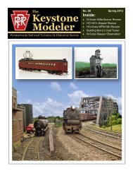
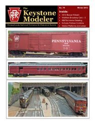
No. 72 <strong>Winter</strong> <strong>2010</strong><br />
Inside:<br />
• Two PRR Gondola Reviews<br />
• Model Roster for Operations on<br />
the on the Panh<strong>and</strong>le<br />
• Build “KASE” Tower in HO<br />
• Kitbash an NA Cabin Car<br />
• Easy Station <strong>and</strong> Tower Signs<br />
•
Published Quarterly by<br />
The PENNSYLVANIA RAILROAD<br />
TECHNICAL <strong>and</strong> HISTORICAL SOCIETY<br />
A non-profit organization<br />
OFFICERS<br />
President Alan B. Buchan<br />
Vice President John J. Consoli<br />
Corporate Secretary Robert D. Brubaker<br />
Asst. Corporate Secretary Ralph M. Weischedel<br />
Treasurer Edward Swain<br />
Marketing <strong>and</strong> Sales Director Fred Freitas<br />
Membership Coordinator Andrew J. Hart<br />
Publisher Frederic V. Shaefer<br />
General Counsel James G. Trope<br />
Public Relations Manager Stan Trzoniec<br />
Station & Archives Chairman Rich Ader<br />
Historian Christopher T. Baer<br />
BOARD OF DIRECTORS<br />
Term Expires <strong>2010</strong> Term Expires 2011<br />
Robert D. Brubaker Chuck Blardone<br />
James B. Winslow Ivan E. Frantz<br />
Term Expires 2012<br />
Alan B. Buchan<br />
John J. Consoli<br />
Edward Swain<br />
THE KEYSTONE MODELER STAFF<br />
EDITOR<br />
Jim Hunter<br />
Jhunter6360@comcast.net<br />
ASSOCIATE EDITOR<br />
Jack Consoli<br />
jjconsoli@comcast.net<br />
NEWSWIRE EDITOR<br />
Steve Hoxie<br />
stevehprr@cox.net<br />
EDITOR EMERITUS<br />
Al Buchan<br />
abbuchan1@comcast.net<br />
CHAIRMAN MODELING COMMITTEE<br />
Elden Gatwood<br />
Elden.J.Gatwood@sad01.usace.army.mil<br />
ART DIRECTOR<br />
Tim Garner<br />
t.a.garner@verizon.net<br />
Send comments <strong>and</strong> corrections to the Editor at:<br />
Jhunter6360@comcast.net<br />
MEMBERSHIP INFORMATION<br />
PRRT&HS, PO Box 54, Bryn Mawr, PA 19010-0054<br />
PRRT&HS MONTHLY E-NEW S<br />
Keystone-e-news-request@lists.keystonepubs.org?Subject=subscribe<br />
Number 72 CONTENTS <strong>Winter</strong> <strong>2010</strong><br />
FROM THE CAB<br />
Jim Hunter, Editor ......................................................................................................... 3<br />
TKM NEWSWIRE<br />
By Steve Hoxie ............................................................................................................... 4<br />
MODEL REVIEW – N-SCALE G26 MILL GONDOLA<br />
By Bob Losse Jr. ........................................................................................................... 6<br />
MODEL REVIEW – HO-SCALE G31B GONDOLA<br />
By Jack Consoli ........................................................................................................... 10<br />
BALANCED LOCOMOTIVE ROSTER FOR OPERATIONS ON<br />
THE PANHANDLE<br />
By Bill Neale ................................................................................................................ 17<br />
KITBASHING AN NA CABIN CAR IN N OR HO<br />
By Claus Schlund ......................................................................................................... MEMBERSHIP INFORMATION<br />
25<br />
MAKING MODEL PRR PRRT&HS, STATION P.O. AND Box 54, TOWER Bryn Mawr, SIGNS PA 19010-0054<br />
By Tim Garner ............................................................................................................. 31<br />
MODELING “KASE” TOWER IN HO<br />
By Chuck Cover ........................................................................................................... 34<br />
Front Cover<br />
C-Liner #9452 on a Coal Drag enters Johnsville<br />
Tim Garner repainted <strong>and</strong> detailed this set of Proto 1000 C-Liners for PRR service on his<br />
PRR Willsburgh Division layout. Tim likes to model cab units fresh from the factory including<br />
pilot coupler covers. He used Scalecoat Brunswick Green <strong>and</strong> a mix of Champ <strong>and</strong><br />
Microscale decals. One mistake, since corrected, is the protruding exhaust stacks. Tim installed<br />
a Soundtraxx DSD sound decoder <strong>and</strong> speaker in the lead unit along with a Miniatronics<br />
LED headlight. A special fog spray was used during the exposure to create the humid<br />
effect.<br />
The Keystone Modeler<br />
This publication of the PRRT&HS is for the purpose of disseminating PRR modeling information.<br />
The copyright is owned by the <strong>Pennsylvania</strong> <strong>Railroad</strong> <strong>Technical</strong> <strong>and</strong> <strong>Historical</strong><br />
<strong>Society</strong> – all rights reserved. It may be reproduced for personal use only. Not for sale other<br />
than by the PRRT&HS.<br />
Manuscripts <strong>and</strong> photographs submitted for publication are welcome. Materials submitted<br />
are considered to be gratis <strong>and</strong> no reimbursement will be made to the author(s) or the<br />
photographer(s) or his/her representative(s). The <strong>Society</strong> reserves the right to reject, for<br />
any reason, any material submitted for publication.<br />
Please contact the editor for information <strong>and</strong> guidelines for submission. If you submit<br />
photos, preferably at 800x600 pixels, not less than 640x480, preferably in TIFF format.<br />
Statements <strong>and</strong> opinions made are those of the authors <strong>and</strong> do not necessarily represent<br />
those of the <strong>Society</strong>.<br />
The Keystone Modeler<br />
CD-ROMs – Issues 49-60 <strong>and</strong> 1-60<br />
A CD-ROM of TKM issues 49-60 is now available for members residing outside of New Jersey<br />
($16.05 for New Jersey members); TKM 1-48 with over 1,500 pages of PRR information<br />
now also is available for $60 for members residing outside New Jersey ($64.20 for New Jersey<br />
Members).<br />
CD-ROMs are also available for issues 1-12, 13-24, 1-24, 25-36, 37-48, <strong>and</strong> 1-48 at a cost of<br />
$15.00 per 12-issues (one year). Each CD-ROM contains a very comprehensive index of all<br />
previous issues. Send a check or money order in US dollars payable to PRRT&HS to<br />
Al Buchan<br />
785 Cornwallis Drive<br />
Mt. Laurel, NJ 08054-3209<br />
To subscribe to The Keystone Modeler, click on the link below <strong>and</strong> send:<br />
mailto:the-keystone-modeler-request@lists.keystone-pubs.org?Subject-subscribe<br />
To unsubscribe, click on the link below <strong>and</strong> send:<br />
mailto:the-keystone-modeler-request@lists.keystone-pubs.org?Subject-unsubscribe<br />
The Keystone Modeler 2 No. 72, <strong>Winter</strong> <strong>2010</strong>
The challenge of paint matching<br />
Modelers never seem to finish their discussion of the “correct”<br />
color for the models they paint. For many, especially prototype modelers,<br />
color is a serious business. What did that car look like when it<br />
was fresh out of the paint shop? Did the paint fade? What color is under<br />
all that soot <strong>and</strong> grime? How did film quality, or lighting conditions,<br />
or computer technicalities affect what I see? Our <strong>Society</strong> even<br />
has a Paint Committee to advise model manufacturers.<br />
Recently, I have had the opportunity to observe first-h<strong>and</strong> how the<br />
same kinds of questions perplex those who have the responsibility to<br />
restore a piece of equipment for display in a museum. Sometimes it is<br />
possible to find traces of earlier exterior colors in the crevices of wooden<br />
equipment or other hard-to-reach places in steel equipment. These<br />
traces can be analyzed by companies which specialize in that kind of<br />
detective work. Traces of paint down through fifteen or sixteen layers<br />
may be discovered. Restorers may consult experts in the history of the<br />
railroad which owned the equipment being restored. Photographic evidence,<br />
if it exists, together with the known limitations of old photographs,<br />
often only in black <strong>and</strong> white, may be examined. Finally, there<br />
is the issue of what period in the history of that piece of equipment<br />
should be represented. If the piece has had several owners or has been<br />
extensively modified, it may not be appropriate to repaint it into its<br />
original color, so the restorer may choose to approximate a later color<br />
<strong>and</strong> lettering scheme.<br />
In this process, just as in modeling, there often is no absolutely<br />
correct choice. The restorer does the best he can, <strong>and</strong>, inevitably,<br />
someone will look at the result <strong>and</strong> declare it is not correct. If you find<br />
yourself being critical of a modeler’s or restorer’s color choice, be prepared<br />
to show how you arrived at your opinion of what is “correct.”<br />
In roughly five months we will be holding the Annual Meetings<br />
again in Camp Hill. Since that location is nearer the epicenter of Pennsy<br />
f<strong>and</strong>om, I hope there will be more models on display. Time to finish<br />
up that project <strong>and</strong> bring it to the Meetings.<br />
This past October was the final Prototype Modelers’ Seminar in<br />
Naperville, Illinois for Sunshine Models. The Seminar will continue,<br />
but Joe Delia of Proto Power <strong>and</strong> ALine models will be in charge. This<br />
event has always been exciting <strong>and</strong> informative, <strong>and</strong> I hope it continues<br />
to be so. For further information, the web site is: http://www.PPW-<br />
ALINE.com.<br />
In this issue of TKM, we have an article by Bill Neale about operations<br />
on his Pennsy layout. Bill’s beautiful railroad recently appeared<br />
in Great Model <strong>Railroad</strong>s <strong>2010</strong>. Jack Consoli has contributed a review<br />
of Tangent Models new G31B. Coincidentally, additional prototype<br />
information can be found in Ed Hawkins’ Railway Prototype Cyclopedia<br />
#19, which appeared just this past fall. Two essays of interest to N<br />
scale modelers also appear this month. Bob Losse, Jr. has written a review<br />
of the new G26 by Eastern Seaboard Models, while Claus<br />
Schlund has kitbashed an NA cabin. We also have Tim Garner’s howto<br />
article on station <strong>and</strong> tower signs, plus Chuck Cover’s article on<br />
scratchbuilding “KASE” Tower from styrene in HO-scale.<br />
Jim Hunter, Editor<br />
The <strong>Pennsylvania</strong> <strong>Railroad</strong> <strong>Technical</strong><br />
& <strong>Historical</strong> <strong>Society</strong><br />
The purpose of the <strong>Pennsylvania</strong> <strong>Railroad</strong> <strong>Technical</strong> & <strong>Historical</strong><br />
<strong>Society</strong> is to bring together persons interested in the history <strong>and</strong> modeling<br />
of the <strong>Pennsylvania</strong> <strong>Railroad</strong>, its subsidiaries <strong>and</strong> its acquired companies.<br />
Our goals are to promote the preservation <strong>and</strong> recording of all<br />
information regarding the organization, operation, facilities, <strong>and</strong> equipment<br />
of the PRR.<br />
The <strong>Society</strong>’s quarterly illustrated journal, The Keystone, has been<br />
published continuously since 1968. Each issue of 64 or more pages contains<br />
illustrated original authoritative articles about locomotives, cars,<br />
other equipment, facilities, <strong>and</strong> operating practices of the PRR. The <strong>Society</strong><br />
also publishes its own thoroughly researched books <strong>and</strong> other materials<br />
concerning PRR history. The Keystone Modeler is also a quarterly<br />
special 30-plus page online publication of the <strong>Society</strong>.<br />
The <strong>Society</strong> meets annually, usually during a weekend in early May,<br />
providing an opportunity for its members to get together <strong>and</strong> learn more<br />
about the PRR. Local chapters around the country also provide members<br />
<strong>and</strong> guests with regular meetings that feature PRR related programs.<br />
Information about our <strong>Society</strong> may be found on our website –<br />
www.prrths.com. To join the <strong>Society</strong>, send $35.00 to:<br />
PRRT&HS<br />
PO Box 54<br />
Bryn Mawr, PA 19010-0054<br />
All memberships are for a calendar year, back issues of The Keystone<br />
for the current year are sent upon joining. Overseas membership<br />
has added postage fees.<br />
PRRT&HS Interchange<br />
Selected <strong>Society</strong> Merch<strong>and</strong>ise of Interest to Modelers<br />
PRR Equipment Drawings on Microfilm<br />
Copies of PRR equipment drawings are available from the <strong>Society</strong>’s<br />
microfilm collection. To order drawings, you must know the drawing<br />
number <strong>and</strong> title. Ordering information <strong>and</strong> lists of arrangement<br />
drawings are available on the <strong>Society</strong>’s website. Go to<br />
www.prrths.com, select National <strong>Society</strong>, <strong>and</strong> then The Interchange. If<br />
you require a printed copy of this information, please send your address<br />
<strong>and</strong> a check for $2.00 made out to PRRT&HS to:<br />
Richard C. Price<br />
779 Irvin Hill Road<br />
McVeytown, PA 17051<br />
The Keystone CD 5<br />
The Keystone CD No. 5, The Glory Days,<br />
covering 1998 to 2002, is now for sale at the<br />
price of $75 for members. New Jersey residents<br />
add $5.25 sales tax. Order CDs from:<br />
Al Buchan<br />
785 Cornwallis Drive<br />
Mt. Laurel, NJ 08054-3209<br />
The Keystone DVD 1<br />
The Keystone DVD No. 1 covering 35<br />
years of The Keystone from 1968 to 2002 is<br />
available. The navigation of this product is<br />
being upgraded as are some of the administrative<br />
notes <strong>and</strong> text. The improved edition<br />
will be ready for ordering soon. Those few<br />
who have already purchased the DVD will<br />
be able to trade it in for a new one when it’s<br />
available. The price of this DVD is $375.<br />
This DVD requires a computer with a DVD<br />
drive. It is NOT a video disk that can be<br />
played on a DVD player for viewing on<br />
your TV.<br />
The Keystone Modeler 3 No. 72, <strong>Winter</strong> <strong>2010</strong>
PRR Product News<br />
Division Point<br />
http://www.divisionpoint.com<br />
PRR/NH/B&M/MEC East Wind Passenger Train – HO<br />
Division Point is taking reservations for brass models of all the<br />
cars in this train. Individual cars will also be available.<br />
Eastern Seaboard Models Corporation<br />
http://www.esmc.com<br />
PRR G26 Gondola – Special Limited Edition – N Scale<br />
Detail Parts – N Scale<br />
ESMC has made available their G26 gon expertly finished <strong>and</strong><br />
weathered by Tom Mann. They have also launched a line of N<br />
detail parts.<br />
InterMountain Railway Company<br />
http://www.imrcmodels.com/index.html<br />
PRR X29 Boxcar – HO Scale<br />
IMRC is scheduled to deliver Red Caboose X29 boxcars in circle<br />
keystone in March <strong>2010</strong>. Planned car numbers are 504219,<br />
504263, 504326, 504388, 504415, <strong>and</strong> 504477. They will all<br />
have a re-weigh date of 1-51. These car numbers model cars<br />
with flat plate ends built new in 1924-25.<br />
JnJ Trains<br />
http://jnjtrains.com<br />
Diesel resin body shells <strong>and</strong> detail parts – N Scale<br />
JnJ has developed resin shells designed to fit on available chassis<br />
from Atlas, Bachmann, Kato, or Life-Like. Available PRR<br />
shells include Erie-built A & B, RF16 A & B, H16-44, <strong>and</strong><br />
SD45.<br />
Middle Division<br />
http://www.middledivision.com<br />
Decals – HO Scale<br />
Middle Division has a very welcome new decal set, HHP-4 for<br />
PRR two bay hoppers in the Circle Keystone scheme. The<br />
PE NNSY LVAN IA is divided to fit between the ribs. Classes<br />
covered include GLA, GLD, GLG, <strong>and</strong> H31. The decals are<br />
printed <strong>and</strong> are awaiting packaging. A corresponding set in O<br />
scale is planned. Order direct from Northern Central Supply at<br />
http://www.northerncentralsupply.com/indexdc.html .<br />
Sunshine Models<br />
(Although Sunshine does not maintain a web presence, a current<br />
summary of products is available at an independentlymaintained<br />
site at www.sunshinekits.com.)<br />
PRR G24 Gondola - HO<br />
With Steve Hoxie<br />
Sunshine has available four versions of the G24 (USRA) gondola.<br />
This class was covered in TKM #7, February 04.<br />
• Kit#92.2 steel sides, Murphy ends, circle keystone decals<br />
(1937-60’s)<br />
• Kit #92.3 steel sides, Murphy ends, Long Isl<strong>and</strong> decals,<br />
(1937-40)<br />
• Kit #92.4 steel sides, Murphy ends, “A” frame for loading automobile<br />
frames, circle keystone decals, (1937-44)<br />
• Kit #92.5 steel sides, WW II replacement ends, circle keystone<br />
decals, (1943-60’s)<br />
Tangent Scale Models<br />
http://tangentscalemodels.com<br />
G31B Gondola – HO Scale<br />
Tangent is offering a ready-to-run, highly accurate model of the<br />
70 ton welded G31B class gondola built by ACF. The cars are<br />
lettered in the circle keystone scheme <strong>and</strong> are available in several<br />
numbers. This class was covered in TKM #17, December ’04.<br />
See product review in this issue of TKM.<br />
Tom Haag Decals<br />
haagtk@aol.com<br />
Shadow Keystone Boxcar Decals – HO Scale<br />
Tom has a new decal set for lettering PRR 50’ boxcars in the<br />
Shadow Keystone scheme with 7” numbers <strong>and</strong> reporting marks<br />
(SK2a <strong>and</strong> SK2b). X45, X47, X50, X52, <strong>and</strong> X56 classes can be<br />
lettered.<br />
Traincat Model Sales<br />
http://www.traincat2.com/<br />
PRR G22B Gondola – N Scale<br />
PRR GRA Gondola – N Scale<br />
Traincat is taking reservations for class G22B <strong>and</strong> GRA gondolas<br />
in brass.<br />
Weaver Models<br />
http://www.weavermodels.com/page76.html<br />
PRR Passenger Sharks BP20 A & B – O Scale<br />
Weaver is taking reservations for ¼” scale brass Passenger<br />
Sharks offered as an A <strong>and</strong> B unit combination or as a single A<br />
unit. 2 <strong>and</strong> 3 rail, Brunswick Green <strong>and</strong> Tuscan Red, with <strong>and</strong><br />
without sound will be available.<br />
The Keystone Modeler 4 No. 72, <strong>Winter</strong> <strong>2010</strong><br />
.
Upcoming Events<br />
January 30-31 – West Springfield, Massachusetts<br />
Amherst Railway <strong>Society</strong> <strong>Railroad</strong> Hobby Show<br />
http://www.railroadhobbyshow.com<br />
March 13 – Peabody, Massachusetts<br />
Spring TRAINing – Hub Division, NMRA<br />
http://hubdiv.org/springshow/index.htm<br />
March 26-28 – Malvern, <strong>Pennsylvania</strong><br />
<strong>Railroad</strong> Protoype Modelers of Valley Forge<br />
Contact Paul Backenstose at prrpaul@aol.com<br />
April 29 – May 2 Camp Hill, <strong>Pennsylvania</strong><br />
PRRT&HS Annual Meeting<br />
http://www.prrths.com/conventions/PRR_Annual.html<br />
Host New Engl<strong>and</strong> Chapter has model room forms available online<br />
so you can fill out more detailed model descriptions in advance.<br />
By doing so, you’ll have more time for fun at the Annual<br />
Meeting <strong>and</strong> you’ll give the TKM staff more to work from in describing<br />
your efforts.<br />
Follow the link above or go to: http://prrths-ne.org/.<br />
June 4-5 – Collinsville, Connecticut<br />
New Engl<strong>and</strong>/Northeast Prototype Modelers Meet<br />
http://www.neprototypemeet.com/Welcome.html<br />
Additional Information<br />
RP Cyc Publishing Co.<br />
http://www.rpcycpub.com<br />
Railway Prototype Cyclopedia Vol. 19<br />
Vol. 19 includes a 53 page article with photos documenting the<br />
G31 class of gondolas. This is an outst<strong>and</strong>ing soft cover reference<br />
for the modeler.<br />
Model <strong>Railroad</strong> Hobbyist Magazine<br />
The Jan/Feb <strong>2010</strong> issue is available for downloading at<br />
http://model-railroad-hobbyist.com<br />
The B&O Modeler<br />
The Baltimore <strong>and</strong> Ohio <strong>Railroad</strong> <strong>Historical</strong> <strong>Society</strong> has the latest<br />
editions available at http://borhs.org/ModelerMag/index.html<br />
The Seaboard-Coastline Modeler<br />
Our friends at the ACL & SAL <strong>Historical</strong> <strong>Society</strong> have the latest<br />
edition of this magazine available at http://www.aclsal.org/ .<br />
Paul Ziesmer, a long-time <strong>Society</strong> member <strong>and</strong> founder of the New Engl<strong>and</strong> Chapter, has a passion for building antique HO kits.<br />
The two PRR P70GR coaches were kits produced by Megow in 1939 or 1940. Paul saw cars like these in Wanamaker’s Store in<br />
Philadelphia in 1943. They are shot on Tim Garner’s PRR Willsburgh Division layout. Tim Garner photo.<br />
The Keystone Modeler 5 No. 72, <strong>Winter</strong> <strong>2010</strong>
Model Review – Eastern Seaboard<br />
Models N-Scale PRR G26 Mill Gondola<br />
By Bob Losse Jr., photos by Jack Consoli unless noted<br />
(Above) Eastern Seaboard Models PRR class G26 65 ft. 6 in. mill gondola. (Below) Eastern Seaboard Models’ two G26 offerings.<br />
Recently, Al Buchan passed on two of Eastern Seaboard<br />
Models Corp’s new N Scale G26 class gondolas. When he did,<br />
he asked me if I could help. He needed a product review <strong>and</strong> I<br />
said yes. This is the first time I’ve ever done this <strong>and</strong> it leaves me<br />
with one thing to say to all you rivet counting sharks out there, I<br />
give good indigestion.<br />
A brief history about the G26 <strong>and</strong> its successors. In October<br />
1930 Altoona built the first 200 cars. From January 1931 through<br />
May 1931 the PRR built 1500 G26 gondolas. Construction was<br />
divided up amongst Altoona, Enola <strong>and</strong> Pitcairn <strong>and</strong> they were<br />
numbered PRR 439010-440709. The Lehigh Valley had 50 cars<br />
built in 1931 by the PRR numbered LV 34000-34049. In 1941<br />
the PRR made some subtle improvements to the design <strong>and</strong> built<br />
the G26A. 700 cars were built by Altoona <strong>and</strong> Pitcairn in the last<br />
quarter of 1941. The Norfolk & Western liked this design <strong>and</strong><br />
had the Virginia Bridge Co. build N&W 70500-70524 G-3 in<br />
1941. In 1949 the N&W received N&W 70525-70549 G-3A<br />
again from Virginia Bridge Co. All of these cars as built were<br />
rated at 70 tons capacity.<br />
So much for the cars as originally built. The LV cars operated<br />
in almost total obscurity <strong>and</strong> were gone from the roster by<br />
1965. As far as I know, no photos of these cars exist. At some<br />
point, the N&W started to upgrade their cars to 77 tons capacity.<br />
I don’t know if any other changes were made to these cars. By<br />
1989 these cars had disappeared from the roster.<br />
The PRR was a little different. In the mid 1960's two distinct<br />
versions, the G26C <strong>and</strong> G26S, would emerge from the shops. The<br />
G26C was basically an upgrading of the two earlier classes <strong>and</strong><br />
used in revenue service. The G26S was a radically different car<br />
<strong>and</strong> was used in company service. This configuration was used to<br />
carry prefabricated switches.<br />
This past Labor Day, I found two in Roanoke, VA working<br />
for NS. Cars for these programs were pulled at r<strong>and</strong>om <strong>and</strong> not<br />
every car was rebuilt. Many found their way to the Holidaysburg<br />
Reclaim Plant, while others were sold to various steel mills, pipe<br />
plants <strong>and</strong> even Pullman St<strong>and</strong>ard.<br />
By April 1, 1976, D-Day for Conrail, 16 G26 <strong>and</strong> 12 G26A<br />
were on the roster still painted PRR. Yes, these cars had serious<br />
longevity.<br />
Not only did they have longevity, they also got around. I<br />
have records showing these cars operated on the B&M, B&O,<br />
CN, CNW, EL, IC, L&N, MKT, SP, SR <strong>and</strong> UP. Unfortunately,<br />
the records weren’t indicating the types of loads. Only that the<br />
cars had been destroyed in wrecks. Some railroads liked proving<br />
this to me so much, that they did it twice.<br />
PRR company photo of G26 #439048, 10-27-30, neg. #E8963, displaying the as-delivered Circle Keystone lettering arrangement.<br />
PRRT&HS collection.<br />
The Keystone Modeler 6 No. 72, <strong>Winter</strong> <strong>2010</strong>
PRR photo of G26 #439048, 10-27-30, neg. #E8964, showing brake end details <strong>and</strong> drop end door arrangement. The cars were<br />
narrower than shorter gondolas to deal with clearance issue due to the long wheelbase. This car is equipped with 2E-F4 trucks.<br />
PRRT&HS collection.<br />
Enough about the prototype, let’s talk about the model. In<br />
checking the dimensions, I used the General Arrangement drawing<br />
that appears in the 1937 Car Builders Cyclopedia <strong>and</strong> Clearance<br />
Diagram E-93171. When I checked the Circle Keystone lettering,<br />
I used various builders <strong>and</strong> in service photos.<br />
The Shadow Keystone paint scheme was easier. I used the<br />
<strong>Pennsylvania</strong> <strong>Railroad</strong> Compendium. For color comparisons, I<br />
used Vol. 2 <strong>and</strong> Vol. 3 of the PRR Color Guides. For anyone<br />
who wants to compare the G26 to the G26A, the General Arrangement<br />
drawing is available from PRRT&HS. PRR diagrams<br />
for the G26 <strong>and</strong> G26A, respectively, are located at:<br />
http://prr.railfan.net/diagrams/PRRdiagrams.html?diag=g26.<br />
gif&sel=gon&sz=sm&fr=<br />
http://prr.railfan.net/diagrams/PRRdiagrams.html?diag=g26a<br />
.gif&sel=gon&sz=sm&fr=<br />
The G26C <strong>and</strong> G26S don’t fit my plans, so I haven’t tried to<br />
locate them.<br />
The only dimension that was way off was the length over<br />
couplers. This has been an ongoing debate within the scale for<br />
many years. No I’m not going there. All of the other dimensions<br />
were within inches. The rivet detail is excellent <strong>and</strong> the various<br />
patterns match the prototype. They also took the time <strong>and</strong> effort<br />
to cast interior details. This is a nice touch, but the way it needed<br />
to be done can cause problems. To get a clear picture of the quality<br />
of this casting, check out the area around the brake wheel. As<br />
built these cars were equipped with early Dreadnaught drop ends,<br />
the ones on this model match <strong>and</strong> work.<br />
Fine details of the parts, inside <strong>and</strong> out, are visible here. This car is equipped with National-type PRR class 2E-F7 trucks, one of<br />
several correct options for these cars.<br />
The Keystone Modeler 7 No. 72, <strong>Winter</strong> <strong>2010</strong>
H<strong>and</strong> brake detail <strong>and</strong> end door shown in dropped position.<br />
I took the time to talk to Bryan Bussey of Eastern Seaboard,<br />
about the two freight car colors used. He told me that both freight<br />
car colors were provided by PRRT&HS. I think he got an FCC<br />
drift card <strong>and</strong> used it on both CK <strong>and</strong> SK models. The CK color<br />
is not orange enough. When it comes to the colors, only real consistency<br />
from manufacturer to manufacturer has been the inconsistency.<br />
Hopefully, the paint committee has come to a consensus<br />
<strong>and</strong> begun to put the right info out to the manufacturers. My observations<br />
about the CK color are that it is a little off. The SK<br />
color on the model is brown, while all of photos I looked at show<br />
a red.<br />
I’ll start with the lettering for the Circle Keystone, CK, car.<br />
It matched up perfectly with the photos I had. The quality <strong>and</strong><br />
detail are amazing. You can read the “ACS” build date as well as<br />
all the other fine print. The Shadow Keystone, SK, car is a different<br />
story. The word “PENNSYLVANIA” <strong>and</strong> the road number<br />
need to be shifted one panel to the left. The keystone <strong>and</strong> all<br />
of the dimensional data are correctly placed. Aside from this<br />
misplacement, all of the other lettering is excellent. At first<br />
glance, you don’t notice this mistake. Bryan told me it would be<br />
corrected for subsequent runs.<br />
This car comes equipped from the factory with body mount<br />
couplers. Typically you’ll only see this in new locomotives or<br />
cabin cars. This caused me some concern, which was very quickly<br />
dispelled.<br />
As anyone in N Scale knows, we have several different types<br />
of couplers on the market now. I used an Intermountain FP7A<br />
<strong>and</strong> an Atlas C-420 as my two test locomotives. The FP7A<br />
comes equipped with Micro-Trains couplers while the C-420 has<br />
Accumate couplers.<br />
I also used an Atlas offset side twin hopper, an Athearn offset<br />
side triple hopper <strong>and</strong> a Micro-Trains boxcar. The Atlas car<br />
has the Accumates, the Athearn car has the new McHenry couplers<br />
<strong>and</strong> we know what the Micro-Trains car has. I was looking<br />
for a variety of things <strong>and</strong> all of my questions were answered.<br />
They all coupled easily <strong>and</strong> smoothly. Coupler height matched<br />
perfectly. There was basically, no difference between the body<br />
mount <strong>and</strong> truck mounted couplers.<br />
Next would be the road tests. Being an apartment dweller, I<br />
don’t have space for the model railroad that I want. What I do<br />
have is a test track. A few years back, Des Plaines Hobbies released<br />
a Pullman <strong>and</strong> it got its turn on my test track. Only by<br />
tweaking the trucks, would these cars tolerate my test track.<br />
Needless to say, any locomotive, freight car, passenger car or cabin<br />
car will get put through its paces on my test track. Using the<br />
five cars <strong>and</strong> two locomotives mentioned above, I put one gon on<br />
the end of the train <strong>and</strong> the other in the middle. I both pushed <strong>and</strong><br />
pulled the cut of cars around the curves <strong>and</strong> through the crossover<br />
switches. These two cars had no problems.<br />
The body mounted couplers <strong>and</strong> the low profile wheels were<br />
used for a reason. Bryan wanted to get the height from rail dimension<br />
correct <strong>and</strong> this was accomplished. I did have one problem<br />
with the road tests. My track is the older 100-million-lbswon’t-wear-out-until-your-gr<strong>and</strong>-kids-have-gr<strong>and</strong>-kids<br />
trackage.<br />
In one direction only, it sounded like the flanges were hitting the<br />
ties. It was coming from the A-end of both cars. When I brought<br />
this to Bryan’s attention, he said it wasn’t the flanges. It was<br />
flash on the axles hitting the coupler box. My X-Acto knife<br />
seems to have fixed this problem.<br />
ESM G26 in as-built Circle Keystone lettering (above) <strong>and</strong> in the later repaint Shadow Keystone lettering (below).<br />
The Keystone Modeler 8 No. 72, <strong>Winter</strong> <strong>2010</strong>
One thing I discovered while investigating this problem, is<br />
how fragile these cars are. The two sides are glued to the metal<br />
frame. Needless to say, these cars need to be h<strong>and</strong>led with kid<br />
gloves. Anyone thinking about doing kit bashing with this car<br />
has been warned. This problem with the trucks should be fully<br />
investigated, so it doesn’t come back to haunt anyone.<br />
My overall impressions are positive. This is a highly detailed<br />
car that h<strong>and</strong>led itself well in tests. The only problems I found<br />
were either fixable or ones we’ve had before. It is a different car<br />
in the way it is assembled, but those differences are a positive. I<br />
took the time to do a little additional research on the welded G33<br />
<strong>and</strong> G37 classes. They share many common dimensions with the<br />
G26. The G33 was built with drop ends while the G37 was built<br />
with fixed ends.<br />
References<br />
The Keystone Modeler, No. 9, April 2004, page 32, G26- classes<br />
historical background <strong>and</strong> photographs.<br />
(Top) Underside view of G26 shows construction of plastic sides<br />
attached to a cast metal floor.<br />
(Above) Correct proportions <strong>and</strong> long length (causing the depth-offield<br />
focus problems) of the ESM G26 is evident in this view.<br />
(Left) Detail showing where flash has been removed from the near<br />
axle. The flash was interferring with the with the coupler pocket pin<br />
only on the A-end of the car.<br />
The Keystone Modeler 9 No. 72, <strong>Winter</strong> <strong>2010</strong>
Model Review – Tangent Scale Models<br />
G31B Gondola<br />
By Jack Consoli, photos by the author unless noted<br />
Class G31B HO injection-molded plastic model.<br />
Let’s just cut to the chase: this is the nicest off-the-shelf,<br />
ready-to-run, state-of-the-art PRR gondola model out there, period.<br />
And unless you are overly concerned about a few details of<br />
the underframe which can’t be seen in any normal model pose,<br />
you won’t end up with a better gon starting with any brass import<br />
or plastic or resin kit, even after you assemble, paint <strong>and</strong> letter it.<br />
Even better news is that (the vast majority of) we modelers need<br />
this car, badly. So let me explain why <strong>and</strong> then get to the details<br />
of the model.<br />
The Prototypes<br />
Following World War II, the PRR’s freight car fleet was in<br />
serious need of repair <strong>and</strong> replacement following the abuse of<br />
supporting the war effort, particularly on many classes of aging<br />
cars. The PRR thus undertook a massive building program of<br />
new freight cars, including gondolas. The first gon type they targeted<br />
was the 52’6” inside length general service mill gondola.<br />
As per their historical mode of operation, they developed a new<br />
design, their first state-of-the-art all-welded gon class in this<br />
case, <strong>and</strong> proceeded to build the 2900 G31 (no-subclass) cars<br />
from 1948 to 1950. These cars featured thirteen welded side<br />
stakes in a W-N-N-N-W-N-W-N-W-N-N-N-W (W=wide,<br />
N=Narrow section stake) pattern. Although the side sheets had a<br />
fishbelly contour, the stakes all ended at the same height across<br />
PRR photo of G31B B-end, showing Universal lever-style h<strong>and</strong> brake <strong>and</strong> A.S.F. trucks.<br />
the length of the car, not extending fully down over the fishbelly<br />
area. The cars had steel floors <strong>and</strong> drop-type 2-rib Improved<br />
Dreadnaught style end doors. The G31 had a 3’6” inside height<br />
<strong>and</strong> 1745 cu.ft. capacity.<br />
The <strong>Railroad</strong> then did something very un-Pennsy-like <strong>and</strong><br />
farmed out the construction of all the subclasses to several of the<br />
major commercial car builders. In the end, there were only three<br />
types of cars: drop-end/steel floor, drop-end/wood floor <strong>and</strong><br />
fixed-end/wood floor. However, since the three commercial<br />
builders opted to construct the last two types per their own respective<br />
preferences, a total of six class designations were required<br />
to keep similarly built cars segregated. Pullman St<strong>and</strong>ard<br />
built the 4800 welded, drop-end/wood floor G31A in three lots<br />
from 1950 through 1952 with their proprietary PS end. This<br />
stamped end door had two large, essentially straight horizontal<br />
corrugations. American Car & Foundry built one lot of 2000 very<br />
similar welded, drop-end/wood floor G31B in March through July<br />
1951, using instead the 2-rib Improved Dreadnaught style end<br />
doors that were used on the G31. They also constructed the 1200<br />
G31D in 1951 <strong>and</strong> 1952, essentially just a fixed-end version of<br />
the same car. These welded cars had 3-rib Dreadnaught ends.<br />
General American, like AC&F, also built both drop end <strong>and</strong><br />
fixed-end, wood floor cars, with corrugated ends. Their 750<br />
G31C of 1951 had 2-rib Improved Dreadnaught end doors <strong>and</strong><br />
The Keystone Modeler 10 No. 72, <strong>Winter</strong> <strong>2010</strong>
their 500 G31E of 1952 had 3-rib Dreadnaught ends. The big difference<br />
between the General American cars <strong>and</strong> all the others<br />
was that they chose to stick with riveted-style construction.<br />
These would be the last riveted gons acquired by the PRR. (The<br />
only other post-war riveted gons, the 2000 46’0” inside length<br />
G34 cars, were actually built earlier, starting in late 1950.)<br />
In addition to the G31-classes, a very similar car, the G35,<br />
factors into this discussion. This class was essentially a slightly<br />
upgraded version of the G31B. The primary differences were that<br />
the newer design incorporated uninterrupted floor stringers <strong>and</strong> a<br />
taller inside height due to a beefed-up top chord configuration.<br />
On the G31’s the crossbearers had straight tops <strong>and</strong> fit up against<br />
the bottom of the floor, requiring the perpendicular stringer<br />
members to be cut <strong>and</strong> fitted in between all the cross members.<br />
On the G35 the crossbearers were dipped on top allowing continuous<br />
floor stringers to pass over top of them along the length of<br />
the car. The G31’s all had a “Z” member for a top chord along<br />
the car sides. For increased strength, the top chord on the G35<br />
was a welded assembly of two horizontal channel members to<br />
form a stronger box beam. Although the inside height of these<br />
cars was 3” taller than the G31B, they had the same side construction<br />
with just a larger top chord. This difference accounts<br />
for the larger cubical capacity of 1745 cu.ft. versus the 1646<br />
cu.ft. of all the wood floor G31-subclasses. The G35 were built<br />
with three different types of flooring.<br />
PRR G31 & G35* – CLASS GONDOLAS (as built)<br />
Class Number Series Quantity Builder Body Ends Floor<br />
G31 363400-366299 2900 PRR Welded<br />
G31A<br />
Drop – 2-rib<br />
Imp.Dreadnaught<br />
Outside<br />
Length<br />
Inside<br />
Height<br />
The Keystone Modeler 11 No. 72, <strong>Winter</strong> <strong>2010</strong><br />
Cubic<br />
Feet<br />
Hold-down<br />
clip location<br />
Steel 54' 8" 3' 6" 1745 Side panels<br />
373950-374949 1000 PS Welded Drop – 2-rib - PS Wood 54' 8" 3' 3" 1646 Side panels<br />
612000-614999 3000 PS Welded Drop – 2-rib - PS Wood 54' 8" 3' 3" 1646 Side panels<br />
374950-375749 800 PS Welded Drop – 2-rib - PS Wood 54' 8" 3' 3" 1646<br />
G31B 371950-373949 2000 ACF Welded<br />
G31C 371200-371949 750 GA Riveted<br />
G31D 375750-376949 1200 ACF Welded<br />
G31E 376950-377449 500 GA Riveted<br />
G35<br />
377450-378449 1000 PRR Welded<br />
378450-379149 700 PRR Welded<br />
379150-379349 200 PRR Welded<br />
Drop – 2-rib<br />
Imp.Dreadnaught<br />
Drop – 2-rib<br />
Imp.Dreadnaught<br />
Fixed – 3-rib Dreadnaught<br />
Fixed – 3-rib Dreadnaught<br />
Drop – 2-rib<br />
Imp.Dreadnaught<br />
Drop – 2-rib<br />
Imp.Dreadnaught<br />
Drop – 2-rib<br />
Imp.Dreadnaught<br />
All classes above: IL = 52' 6", IW = 9' 6", EXH = 10' 7", Capacity = 70 tons<br />
PS = Pullman St<strong>and</strong>ard Car Manufacturing Co.<br />
ACF = American Car & Foundry<br />
GA = General American Transportation Corp.<br />
Wood 54' 8" 3' 3" 1646<br />
Wood 54' 8" 3' 3" 1646<br />
Wood 54' 8" 3' 3" 1646<br />
Wood 54' 0" 3' 3" 1646<br />
Wood 54' 8" 3' 6" 1745<br />
Nailable steel 54' 8" 3' 6" 1745<br />
Composite 54' 8" 3' 6" 1745<br />
Outer side of top<br />
chord<br />
Outer side of top<br />
chord<br />
Outer side of top<br />
chord<br />
Outer side of top<br />
chord<br />
Outer side of top<br />
chord<br />
Outer side of top<br />
chord<br />
Outer side of top<br />
chord<br />
Outer side of top<br />
chord<br />
Note: All the G31 classes had the same height sides: the G31 had larger capacity due to the steel floor – the wood floor consumed approximately 100<br />
cubic feet of volume. The capacity in the ORER is listed as 1646 for all the wood floor cars, but the G31A <strong>and</strong> G31B were stenciled as being 1647 cubic<br />
feet.<br />
* Note: The wood floor G35 essentially the same as G31 design except for having main crossbearers dipped to allow for continuous passage of the<br />
floor stringers between the bolsters <strong>and</strong> the side height extended by the top chord to yield the same capacity as the steel floor G31.<br />
REBUILDS Date Details<br />
G31F Rebuilt from class G31 1960<br />
G31H Rebuilt from class G31 1966 StanRay corrugated side panels<br />
G31K Rebuilt from class G31A 1967<br />
G31L Rebuilt from class G31B 1967<br />
G31M Rebuilt from class G31C 1967<br />
G31N Rebuilt from class G31D 1968<br />
G31P Rebuilt from class G31E PC era<br />
G35A Rebuilt from class G35 PC era<br />
Breakdown <strong>and</strong> details of the G31- <strong>and</strong> G35-class gondolas.
There were a total of 12,150 G31-class cars constructed;<br />
14,050 if the G31 – plus the similar G35 – are included. With the<br />
loss of many older cars during the decade preceding their construction,<br />
The G31/G35 classes comprised a very significant part<br />
of the PRR’s gondola fleet. To illustrate the magnitude of the<br />
place in the PRR roster these cars filled, look at the totals from<br />
the Official Railway Equipment Register roster dated October<br />
31, 1952 (issue cover date January 1953). Keep in mind there<br />
were almost 1000 G35 not yet built as of this date.<br />
ALL FREIGHT CARS<br />
Number of Percent of<br />
Freight Car Type Cars Total<br />
Open Hopper 75,077 38.57<br />
Box Car 68,145 35.01<br />
Gondola 44,594 22.91<br />
Flat Car 3,189 1.64<br />
Covered Hopper 2,297 1.18<br />
Stock Car 1,327 0.68<br />
Total 194,629 100.00<br />
Here is the breakdown by gondola class (with subclass included<br />
within the base class for simplicity).<br />
PRR Gondola Number of Percent of<br />
Class<br />
Cars Total<br />
GR 3,689 8.27<br />
GS 882 1.98<br />
G21 1 0.00<br />
G22 6,127 13.74<br />
G24 545 1.22<br />
G25 2,461 5.52<br />
G26 2,348 5.27<br />
G27 4,495 10.08<br />
G28 1,895 4.25<br />
G29 2,981 6.68<br />
G30 997 2.24<br />
G31 12,149 27.24<br />
G32 2,100 4.71<br />
G33 950 2.13<br />
G34 2,000 4.48<br />
G35 974 2.18<br />
Total 44,594 100.00<br />
Here is the breakdown by sub-class for G31/G35.<br />
PRR Gondola Number of Percent of<br />
Class<br />
Cars Total<br />
G31 2,900 6.50<br />
G31A 4,799 10.76<br />
G31B 2,000 4.48<br />
G31C 750 1.68<br />
G31D 1,200 2.69<br />
G31E 500 1.12<br />
G35 974 2.18<br />
Total 13,123 29.41<br />
So the bottom line here is that in the early 1950’s gons made<br />
up close to one quarter of the total PPR fleet of nearly 200,000<br />
cars <strong>and</strong> of those, almost one in three was a G31/G35. PRR <strong>and</strong><br />
non-PRR modelers alike need these cars.<br />
Additional background can be found in the previous TKM<br />
articles on the G31:<br />
• G31, G31A/B/D, G35 Gondolas – Vol. 16, page 23: background,<br />
diagram, numbers <strong>and</strong> quantities, photos.<br />
• G31, G31A/B/D, G35 Gondolas – Vol. 17, page 24: supplemental<br />
photos.<br />
• G31C/E Gondolas – Vol. 17, page 8: background, diagram,<br />
numbers <strong>and</strong> quantities, photos.<br />
The Model<br />
There is frankly very little to say about this model because it<br />
is so well done. The construction of the car is fairly typical, the<br />
execution is exemplary. The sides, ends <strong>and</strong> underframe members<br />
are a one-piece injection molded part. Small details including<br />
the tack boards, defect card holder, poling pockets, end sill<br />
gussets, drop door latches <strong>and</strong> weld seams (including those on<br />
the inside of the car) are molded into the body where appropriate.<br />
Especially well executed are the shallow oval slots along the face<br />
of the corner posts that aided in the welding process of the prototype<br />
as well as the small holes along the length of the top chords.<br />
Note also that the non-symmetric end sills on the car are properly<br />
recreated; this is not a mistake. Whereas the A-end sill has a<br />
shallow taper, the B-end sill has a much deeper taper to extend<br />
the draft gear outward <strong>and</strong> provide space from a coupled car for<br />
the h<strong>and</strong> brake <strong>and</strong> platform protruding from the end of the car.<br />
(Above left) A ¾-view of G31B model. (Above right) G31B A-end showing the shallow sill, drop end door, side bracket grab, etc.<br />
Note that the drop steps are not mangled here. The inside leg was vertical, but the outer leg was angled due to its being attached<br />
out on the angled part of the corner post.<br />
The Keystone Modeler 12 No. 72, <strong>Winter</strong> <strong>2010</strong>
(Right top) Inside view illustrating the floor<br />
detail, corrugated ends, weld seams <strong>and</strong> top<br />
chord holes. The recesses on the top of the<br />
corner posts <strong>and</strong> the door top stiffener rivets<br />
are prototypically correct as well.<br />
(Middle) Underside view of G31B showing<br />
brake gear <strong>and</strong> partial-depth center sill <strong>and</strong><br />
crossbearer members with steel weights buried<br />
beneath.<br />
(Bottom) Fine detailing of the hold down<br />
clips, retainer valve, <strong>and</strong> side ladder.<br />
The Keystone Modeler 13 No. 72, <strong>Winter</strong> <strong>2010</strong>
The rest of the fine details are separately attached<br />
parts that appear very close to proper scale<br />
size <strong>and</strong> cross-section. All the grab irons, ladder<br />
rungs <strong>and</strong> cut levers are wire parts. The half-bracket<br />
grabs on the left end of the sides <strong>and</strong> the half-ladders<br />
on the right ends are beautifully done. The retainer<br />
valve <strong>and</strong> piping, perforated brake platform (US<br />
Gypsum type), drop steps <strong>and</strong> air hoses are all nicely<br />
done as well. Tangent is to be thanked for their effort<br />
expended on the h<strong>and</strong> brake gear. Prototypically correct<br />
<strong>and</strong> scale-size lever-style h<strong>and</strong>brakes so common<br />
on drop-end gondolas have historically been a problem<br />
for modelers. Tangent tooled both Universal <strong>and</strong><br />
Equipco styles, each in two parts: the gear housing<br />
with attached chain <strong>and</strong> a separate lever. Even better,<br />
Tangent is selling them separately, two of each type<br />
on a single sprue per set. All their decorated G31B<br />
come with the Universal style. The prototypes are reported<br />
to have been equipped with a mixture of 500<br />
Universal, 1250 Equipco <strong>and</strong> 250 Klasing sets of<br />
brake gear. The underframe air brake gear, piping,<br />
rods <strong>and</strong> levers appear to be molded <strong>and</strong> applied in<br />
two sections. The delicate, open hold down clips attached<br />
along the outside face of the top chord have<br />
been cleanly molded onto a separate strip, <strong>and</strong> then<br />
applied along the top of the sides.<br />
The 2000 G31B were equipped with PRR class<br />
2E-F22B <strong>and</strong> 2E-F22C trucks. The first 1500 cars<br />
had 70 ton A.S.F. A-3 Ride-Control trucks <strong>and</strong> the<br />
last 500 had National C-1 trucks. Since no appropriate<br />
A.S.F. trucks existed for these models, Tangent<br />
tooled the 70 ton A-3 Ride-Control truck to fill this<br />
void. They are very nicely detailed <strong>and</strong> include casting<br />
markings <strong>and</strong> brake shoes along with the correct<br />
configuration of four visible springs.<br />
Fortunately, Tangent offers these trucks for sale separately<br />
also. (The 70 ton National C-1 trucks are available from Atlas if<br />
you care to model a car with them applied. If you replace the<br />
Tangent trucks, you can always use these A.S.F. trucks elsewhere<br />
as they were used under a number of gon classes.) The<br />
models are equipped with Kadee “scale” Whisker ® shank couplers.<br />
I have only three minor criticisms of this model. The first is<br />
that the prototypes only had one defect card holder. It was on the<br />
side of the car such that when faced, the B-end of the car would<br />
be to the viewer’s left, as seen in the prototype photo above. The<br />
model has two; one on each side of the car. This can be easily<br />
(Top) Drop end door <strong>and</strong> latch hardware, Universal lever h<strong>and</strong>brake gear,<br />
cut levers <strong>and</strong> corner ladders are visible here. (Above) Tangent 70-ton<br />
A.S.F. A-3 Ride-Control trucks. (Bottom) Decorated G31B in its as-built lettering<br />
scheme with gray wood floor.<br />
remedied with one flick of your h<strong>and</strong>y #17 X-Acto knife blade.<br />
The second item is that although the 26 hold down clips are included<br />
along each top chord, the prototype also had one mounted<br />
at an angle on each of the 2 nd <strong>and</strong> 3 rd side stakes in from each end<br />
for a total of 30 per side. Underst<strong>and</strong>ably, these would have been<br />
pretty much impossible to mold onto the model side stakes. It<br />
would require minimal effort to add these as separate bent plastic<br />
or metal rod pieces by the modeler. The last item is that the drop<br />
end doors of the assembled models are glued in (quite well), as<br />
shipped from the factory. This is only an issue if you wish to<br />
configure your car with the doors in their dropped positions.<br />
The Keystone Modeler 14 No. 72, <strong>Winter</strong> <strong>2010</strong>
I had heard that gluing in the doors was a compromise to keep<br />
the car cost down by eliminating all the extra work to decorate<br />
<strong>and</strong> h<strong>and</strong>le parts which have numbers on them that need to match<br />
the car to which they are applied. I started to try to free one with<br />
the sharp tip of a #11 blade <strong>and</strong> I think it is possible, if care is<br />
exercised. Any minor damage to the parts could be disguised as<br />
“weathering” anyway as prototype end doors were abused relentlessly.<br />
I have not yet purchased the kit version of the car (for<br />
conversions) to know for certain, but I am hopeful that the doors<br />
are not assembled to those bodies.<br />
Undoubtedly, some modelers may complain that some of the<br />
upper underframe member details are missing due to their<br />
“space” being occupied by the car weights. I personally would<br />
much prefer to have the car properly weighted right out of the<br />
box at the expense of some details I will never see anyway once I<br />
place the car on the rails, than have to fiddle around trying to<br />
squeeze little bits of weight here <strong>and</strong> there later. Agreed, that on<br />
some freight cars this approach could be a visual problem, but<br />
that is not the case on a gondola with low hanging sides like this.<br />
If it really bothers you, you can easily pop out the floor piece by<br />
pushing up on its underside at the ends of the car <strong>and</strong> then peel it<br />
out once you get the first end lifted, remove the weights, glue in<br />
a bunch of little styrene pieces <strong>and</strong> replace the floor, <strong>and</strong> then<br />
add the weight back via some other means: knock yourself out.<br />
Finishing<br />
The decorated cars are painted a color that is well within the<br />
bounds of what we believe PRR Freight Car color of the early<br />
1950’s to be. The simulated wood floors are painted a neutral<br />
gray. Since on the prototypes the floors of these cars were known<br />
to be unpainted even when new, the gray is intended to give the<br />
modeler a convenient starting point for getting a weathered bare<br />
wood look on the model. The air hoses are even painted black on<br />
their simulated rubber section. The truck sideframes are unpainted<br />
black plastic.<br />
All the lettering is properly applied in white. Note that with<br />
the dispersal of construction of the G31- <strong>and</strong> G35 classes<br />
amongst several builders, a few non-st<strong>and</strong>ard lettering practices<br />
appeared on the cars when built. Although the historically correct<br />
abbreviation on the PRR for the application of one-wear wrought<br />
steel wheels was “1W WRT ST WLS” (dashes <strong>and</strong> periods not<br />
withst<strong>and</strong>ing), ACF stenciled both the G31B <strong>and</strong> G31D “1W<br />
WRT STL WLS” while General American stenciled the G31C<br />
<strong>and</strong> G31E “1W WRT ST WHLS”. ACF also used an angled line<br />
in the fraction in the spring travel data, whereas st<strong>and</strong>ard practice<br />
dictated a horizontal line. Further, ACF also formatted the “THIS<br />
CAR PROVIDED WITH HOLDDOWN CLIPS…” note in the<br />
center of car side to be both right- <strong>and</strong> left-justified, whereas on<br />
most all other classes, the note was only left-justified. Although<br />
PRR practice seemed to vary somewhat, the G31B were delivered<br />
with the “B” suffix in the class notation as a full height 4”<br />
capital letter. In later repaints, some cars received the smaller 3”<br />
capital “B”. Note also that in the period these various classes<br />
were being built, the PRR was in the process of moving some<br />
stenciling to the ends of the cars <strong>and</strong> then further rearranging<br />
their positions on the ends. Tangent got all these subtleties correct<br />
on their G31B.<br />
Other Versions?<br />
The G31B is a great addition to the stable of available models<br />
out there, but what does the introduction of this model mean<br />
to us modelers to help complete the whole picture of the PRR<br />
gondola fleet? How do we get to a G31, G31A, G31C, G31D,<br />
G31E, G35 <strong>and</strong> all the later rebuilt subclasses? As mentioned<br />
above, a significant part of the PRR gondola fleet was made up<br />
of this collection of cars.<br />
We certainly hope at a minimum, Tangent considers releasing<br />
this car in the later Shadow Keystone <strong>and</strong> Plain Keystone<br />
paint schemes as this is a fairly simple extension of their product<br />
line <strong>and</strong> is particularly appropriate as these cars lasted through<br />
<strong>and</strong> past the end of the PRR era.<br />
How similar are all the other classes mechanically? Ignoring<br />
little details like brake gear <strong>and</strong> trucks that can be very easily<br />
changed/corrected by the modelers (even on a decorated model),<br />
there are only a few features of the car to be discussed. The G31<br />
<strong>and</strong> first two groups of G31A had the hold-down clips attached to<br />
the side panels of the car (in addition to the two at each end on<br />
the side stakes). The last group of G31A, 374950 – 375749, all<br />
the subsequent subclasses built new, <strong>and</strong> the G35 had the clips<br />
along the edge of the top chord as on the Tangent model. Retooling<br />
the body for the side-mounted clips would appear to be a significant<br />
undertaking/expense, <strong>and</strong> I frankly don’t know how it<br />
could be done to yield open clips, short of applying them as separate<br />
parts.<br />
(Left) G31B B-end showing well detailed brake gear <strong>and</strong> end lettering. (Right) Enlargement of the fine small lettering <strong>and</strong> the<br />
open hold-down clips.<br />
The Keystone Modeler 15 No. 72, <strong>Winter</strong> <strong>2010</strong>
On the other h<strong>and</strong>, the modeler could easily cut off the G31B<br />
top chord clips or remove the entire piece they are molded onto<br />
<strong>and</strong> replace it with a styrene strip. Although adding the clips by<br />
h<strong>and</strong> is a little tedious, doing it with a plastic-bodied car is the<br />
best case scenario. (See the G31C/E construction article in TKM<br />
Vol.17.)<br />
The G31C <strong>and</strong> G31E were riveted construction cars. I would<br />
not expect Tangent to do these cars as they are almost completely<br />
different from the tooling perspective <strong>and</strong> were the smallest<br />
groups of cars of the lot – not likely a good business decision for<br />
Tangent. Even from the modeler’s perspective, a better starting<br />
point to build either subclass would probably not be the G31B.<br />
Since the drop end doors are tooled as separate parts on the<br />
model, Tangent could very easily tool a new Pullman St<strong>and</strong>ard<br />
three-corrugation style door. With this new door <strong>and</strong> some minor<br />
changes to the painting details they could then produce cars<br />
matching the last group of G31A with the hold-down clips along<br />
the top chord. If a modeler then purchased the unpainted kit version<br />
of this car with the P.S. door, making the change to the holddown<br />
clip location would be all that is required to get the first<br />
two groups of G31A. This largest subclass of the lot would then<br />
be covered. There are no P.S. ends currently on the market so if<br />
Tangent does not tool one, the modeler would have to scratchbuild<br />
these parts to make the G31A. (Note that after a few<br />
years, the end doors on all these classes seemed to get mixed up<br />
due to repairs, so some G31A did eventually end up with G31B<br />
doors.)<br />
Similarly, the straight G31 could be made from the existing<br />
G31B body <strong>and</strong> end doors by making the change to the holddown<br />
clips. The only other part needed is a steel floor. Since this<br />
is also a separate part, it could be tooled by Tangent or built by<br />
the modeler to get a G31.<br />
The G31D has fixed ends, but is otherwise very similar to the<br />
G31B since ACF constructed both classes. It would appear that<br />
Tangent could accurately address this subclass by tooling just the<br />
new fixed end <strong>and</strong> changing the painting accordingly. The particularly<br />
advantage to building this car is that it opens the previously<br />
untouched market for the “skid <strong>and</strong> cover” cars which the<br />
PRR specially converted to haul steel coils <strong>and</strong> plates. The G31E<br />
<strong>and</strong> G31D were similarly equipped <strong>and</strong> were the PRR’s first large<br />
scale venture into this special equipment. If this subclass is not<br />
tooled, it still would not be a particularly difficult kitbash.<br />
Side view of G31B.<br />
The G35 differed from the G31B primarily in its top chord<br />
construction <strong>and</strong> some underframe details (that would be obscured<br />
by the weights in this G31B model). The cars were also<br />
built with three variations of flooring. Tooling the top chord<br />
changes might be messy, but it makes for a very simple kitbash<br />
from the existing car. I have already started that conversion, so<br />
buy some undecorated cars <strong>and</strong> get ready for the details in the<br />
next issue of TKM.<br />
Penn Central <strong>and</strong> Conrail modelers need G31-‘s as well, but<br />
most/many of the classes were modified in the late 1960’s to become<br />
new subclasses (see the table above) <strong>and</strong> some physical<br />
changes would be required beyond just paint <strong>and</strong> lettering. I am<br />
not fully familiar with all the changes, but I expect it to be a fairly<br />
tangled web. It may be quite unrealistic for Tangent to spend<br />
the money necessary to make the tooling changes required, so<br />
this is likely to be a project left to us modelers. We have a G31L<br />
conversion article already in pipeline for the next issue as well.<br />
Summary<br />
So to summarize: this G31B is an excellent model <strong>and</strong> goes a<br />
long way towards allowing a significant group of related cars to<br />
be modeled, compared to what was previously available (nothing).<br />
If Tangent will do the later paint schemes, tool the G31D<br />
fixed end <strong>and</strong>/or possibly the PS end door, we modelers would be<br />
in great shape. If they tool the skids <strong>and</strong> covers… wow.<br />
Bottom line here though is that we consumers need to show<br />
our support of their efforts by buying the products. Additionally,<br />
please contact Tangent <strong>and</strong> let them know what you’d like to see<br />
as this “marketing” information can be valuable to them in<br />
choosing where to direct any potential future energy regarding<br />
this project.<br />
References<br />
• The Keystone, December 1980, page 35, article <strong>and</strong> photographs.<br />
• Rails Northeast, November 1976, Circle Keystone painting &<br />
lettering diagram.<br />
• Railway Prototype Cyclopedia: RP CYC 19, Ed Hawkins, page<br />
113, G31- article, photos <strong>and</strong> data, (also similar cars on other<br />
roads).<br />
• Tangent Models website, http://tangentscalemodels.com, prototype<br />
information <strong>and</strong> photos.<br />
The Keystone Modeler 16 No. 72, <strong>Winter</strong> <strong>2010</strong>
Balanced Locomotive Roster<br />
for Operations on the Panh<strong>and</strong>le<br />
By Bill Neale<br />
An eastbound symbol freight moves through Steubenville, Ohio behind by M1A #6734.<br />
Many modelers like to put their models to work, doing in<br />
model form what their prototypes did. More than just circulating<br />
a train, prototype operation implies a purposeful use of the<br />
equipment that replicates the actions <strong>and</strong> events that might have<br />
taken place on the real PRR. Prototype operations provide a<br />
meaningful reason for each train, which enhances the experience<br />
of the operator. It affects the way we think about the trains we<br />
run <strong>and</strong> can increase our enjoyment of the fine equipment we<br />
create by putting the rolling stock into context. Of course not<br />
everyone enjoys operations <strong>and</strong> frankly not all operating sessions<br />
are enjoyable. However, I think many modelers of the<br />
PRR intend to have operating sessions even if that point is some<br />
distance in the future. They might find my experiences interesting.<br />
I model the PRR Panh<strong>and</strong>le in 1939, so only steam engines<br />
need apply for the front end of trains. Maybe it’s obvious, but<br />
which engines do what tasks? What are the limitations I have<br />
found putting together a roster to operate my railroad? Which<br />
br<strong>and</strong>s of models seem to work best for what service? At least<br />
once or twice during every operating session I hold, I am asked<br />
about the br<strong>and</strong> of locomotives, <strong>and</strong> what modifications I have<br />
done to get then to run nicely. Perhaps my experiences can help<br />
others, so I put together this synopsis of my approach to an engine<br />
roster, <strong>and</strong> related it to how I operate my section of the<br />
PRR. This is not a recitation of PRR practice; instead, it is focused<br />
on how to model operations on the PRR using today’s<br />
models.<br />
In the process of developing an operating scheme, some of<br />
the prototype operations of various trains were modified to fit<br />
the model. Over time, the make-up <strong>and</strong> importance of certain<br />
trains change. Maybe train PH-10 starts out as a hot-shot freight<br />
in the early 20 th century, degrades to a mixed freight in the<br />
1930’s, but becomes more important as traffic patterns shift<br />
again in the 1950’s. For model operations, I may choose to use<br />
PH-10 as a mixed freight, which may not be accurate for this<br />
train <strong>and</strong> time period, so please be cautious about taking the information<br />
in the modeling context <strong>and</strong> assuming it applies to the<br />
prototype PRR. In some cases I manufactured train numbers<br />
because I simply could not find the right information at the time.<br />
The Keystone Modeler 17 No. 72, <strong>Winter</strong> <strong>2010</strong>
(Top) The Steubenville Shifter behind a B6sb spots cars at<br />
the freight house. (Left) L1S #1122 drifts downgrade on<br />
PH-125. (Bottom left) An I1SA shoves hard against an N5B<br />
cabin car <strong>and</strong> a train of loaded H21A hoppers.<br />
Like most model railroads, my representation of the<br />
Panh<strong>and</strong>le is selectively compressed. I represent about 15-20<br />
miles of real track in three scale miles. My tracks are shorter<br />
<strong>and</strong> my grades are steeper than the prototype, but those compromises<br />
are very common on most model railroads. I have<br />
one main yard (Weirton Junction), one complex industrial<br />
area (Steubenville), <strong>and</strong> a multi-track mainline with a long<br />
2% grade that requires helpers. The operating pattern is<br />
based on many through trains interacting with the local facilities.<br />
I have substantial staging at both ends of the modeled<br />
section to support a large number of trains that roll across my<br />
section of the PRR.<br />
Let’s start with the through trains. The hottest trains on<br />
the railroad are powered by M-class engines. In 1939, the<br />
big 4-8-2 M1 <strong>and</strong> M1A Mountains were the most modern<br />
power available. These manifests are 20 to 25 cars long, <strong>and</strong><br />
consist of reefers, boxcars, <strong>and</strong> tank cars. My desire is to require<br />
a pusher if the train is more than about 22 cars. Manifests<br />
PH-10, VL-2, <strong>and</strong> JC-5 have BLI M1A power. CIN-1<br />
has a Westside M1A. The Westside has more pulling power<br />
than I like, so I keep it on the Westbound – down bound<br />
trains. That disguises the extra tractive effort this engine has.<br />
I also run a 30 car eastbound stock extra that is M1A powered.<br />
I intend to put a Sunset M1 (short tank) in service<br />
soon, as an alternative engine for any of these trains. However,<br />
the Broadway engines are the best for this service as<br />
they are reliable <strong>and</strong> pull just enough to occasionally need a<br />
pusher.<br />
The Keystone Modeler 18 No. 72, <strong>Winter</strong> <strong>2010</strong>
Trains PH-4 <strong>and</strong> PH-7, PH-11, <strong>and</strong> CIN-2 are symbol<br />
freights that are mixed in consist <strong>and</strong> do some work<br />
on the railroad. Often these trains will pick up or set off<br />
cars at Weirton, <strong>and</strong> a few trains also stop at Steubenville<br />
yard. I use I1’s, L1’s <strong>and</strong> sometimes N1’s, on<br />
these trains. The Precision Craft Models I1SA Decapod<br />
is one of the best plastic models done to date. However,<br />
in stock form, it did not pull sufficiently to meet the 20-<br />
22 criteria on the hill. I did some modifications to improve<br />
the pulling power <strong>and</strong> now they pull just fine. The<br />
N1’s are Westside models, <strong>and</strong> are some of the finest<br />
running five-axle brass engines ever made in my opinion.<br />
The N1’s required some TLC to straighten the<br />
valve gear <strong>and</strong> rods so they would run correctly.<br />
The PFM L1S is another nice running engine, but I<br />
found that a new NWSL gear box <strong>and</strong> can motor made it<br />
even better. The older Japanese built engines tend to<br />
have a sturdier frame <strong>and</strong> better running gear than later<br />
imports. I had to add weight to most of my brass engines<br />
to get them to pull better. However, I don’t want<br />
the L-class engine pulling more than the N-class, so balance<br />
<strong>and</strong> moderation are needed when setting up the engines.<br />
Casting an H6SB boiler out of depleted uranium<br />
so that it will drag 150 cars up the hill defeats the purpose<br />
of needing certain engines to do certain jobs.<br />
All along this part of the panh<strong>and</strong>le, small mines<br />
dotted the region in the 1930’s. I use PFM L1S locomotives<br />
to h<strong>and</strong>le the mine shifters along the mainline,<br />
one each way. These are trains PH-124 <strong>and</strong> PH-125<br />
(these are manufactured numbers but are within the<br />
scheme of train numbering that was used in the region).<br />
(Top right) H9S <strong>and</strong> B6SB yard shifters wait by the<br />
Weirton Yard Office. (Right) An I1SA backs down to<br />
an empty coal train in Weirton. (Bottom) The Weirton<br />
Shifter moves an N6B cabin car as a road freight<br />
rolls by.<br />
The Keystone Modeler 19 No. 72, <strong>Winter</strong> <strong>2010</strong>
(Above) The Steubenville Shifter, a B6SB 0-6-0, services Central Sewer Pipe <strong>and</strong> Supply Co. over some complex industrial trackage.<br />
(Below) A hard-working I1SA “Hippo” charges into Steubenville with a loaded coal train.<br />
The L1S locomotives operate exceptionally<br />
smoothly, so they make excellent<br />
engines to switch with, <strong>and</strong> they<br />
have enough muscle to h<strong>and</strong>le 20-25 coal<br />
loads on the hill. Maybe an I1 would be<br />
a better choice if there were more mines,<br />
or an H10S if the line were more level,<br />
however, the Mikado seems to have the<br />
right balance of power for this service.<br />
Coal service out of the Burgetts<br />
Branch is I1-powered. Because I want<br />
the Burgetts Branch Coaler to operate<br />
without the need of a helper, I used a<br />
PFM I1 on this train. The PFM has a<br />
Precision Scale gearbox <strong>and</strong> a can motor,<br />
so the operation is smooth <strong>and</strong> reliable.<br />
Extra weight was added to this engine to<br />
ensure it was sufficiently strong enough<br />
to h<strong>and</strong>le the eastbound (up bound) leg<br />
of its turn. On the prototype, coal from<br />
Burgettstown moved eastward. On my<br />
model, the coal moves down to Weirton,<br />
<strong>and</strong> empties go back up the hill to the<br />
Burgettstown mines.<br />
The Keystone Modeler 20 No. 72, <strong>Winter</strong> <strong>2010</strong>
(Top) K4s #439 on Train #412 paused in Steubenville next to a female admirer.<br />
(Bottom) K4s #1122 with a mate on Train #10 rolls through Bertha.<br />
Every day, a train load of steel products departs<br />
Weirton Yard for the east. Generally this consists of<br />
10-15 cars of plate steel, <strong>and</strong> 20-25 cars of rolled steel.<br />
The plate steel is heading for the Navy Yards on the<br />
East Coast. For this train, one or two PFM I1s are<br />
usually on the front end pulling <strong>and</strong> an I1 pusher is on<br />
the back end. Usually the pusher is a PFM Decapod,<br />
but lately I have been using a PCM Decapod very successfully.<br />
It gives enough push to get the train over<br />
the hill, without overpowering the back end of the<br />
train. Sometimes an N1S subs for one of the lead I1SA<br />
locomotives. In its modern configuration, this was the<br />
last train I saw on this section of the prototype Panh<strong>and</strong>le.<br />
Even with modern diesels, it still needed a<br />
pusher at the back end.<br />
The other big train eastbound train is metallurgical<br />
coal out of Mingo Junction, east to Pittsburgh. This<br />
is the heaviest <strong>and</strong> longest train on the Panh<strong>and</strong>le,<br />
usually 35-40 loaded cars. Usually two I1 pushers are<br />
needed, <strong>and</strong> two lead I1’s also. One session required<br />
the Weirton Yard engine to push, just to get the train<br />
up Hanlin Hill. The Weirton crew got extra pay that<br />
day as it took all five engines to get the coal train moving.<br />
I should note that some photographic evidence<br />
shows that eastbound prototype coal trains were of<br />
moderate size in steam days, <strong>and</strong> had one engine on<br />
the front <strong>and</strong> one engine on the back when they<br />
climbed Hanlin Hill.<br />
The Keystone Modeler 21 No. 72, <strong>Winter</strong> <strong>2010</strong>
An I1SA still equipped with extended piston rods rolls past the Diamond Café in Steubenville with a mixed freight.<br />
Passenger service is supported by a fleet of K4S Pacific’s.<br />
Most of these are Broadway Limited engines, which are reliable,<br />
<strong>and</strong> capable of h<strong>and</strong>ling a normal 8-9 car passenger train on the<br />
hill. Double headed K4S engines are used on the front of #10,<br />
the eastbound mail, a significantly long train. A couple of remotored<br />
PFM K4S locomotives also supply power for the Spirit<br />
of St. Louis (#30 & #31), <strong>and</strong> the Cincinnati Limited (#40 &<br />
#41). The PFM’s have extra weight added <strong>and</strong> have just a tiny<br />
bit more pull than the Broadway engines. Both run smoothly at<br />
slow speed. Local service is provided by a Westside G5S, <strong>and</strong> a<br />
rebuilt Alco E5S (Alco made some of the worst running brass<br />
engines ever imported. My E5S was gutted <strong>and</strong> a Bowser mechanism<br />
was installed by my good friend Rev. Jon Barker).<br />
Peddler freights (PH-120 & PH-121) are headed by H10S<br />
engines. I have three Sunsets <strong>and</strong> one re-motored/re-geared Gem<br />
that share this work. I rotate the four engines across the two locals<br />
during the year. That ensures I have backup power should<br />
any engine fail during a session. The Sunsets are my favorite because<br />
they have better proportions <strong>and</strong> a lighter look than the old<br />
Gem, but the Gem holds her own when in service.<br />
A Sunset H9S is assigned to Weirton Yard as the primary<br />
shifter on the east end, while a B6SB or a B6S holds down the<br />
west end job. The west end shifter pulls <strong>and</strong> spots cabin cars,<br />
<strong>and</strong> moves cuts of cars from the west end of trains in the receiv-<br />
ing yard. The east end job has the heavy classification work.<br />
The B6SB is a Sunset model which I am very pleased with. The<br />
B6S is from Overl<strong>and</strong>, <strong>and</strong> while a beautiful engine, it has trouble<br />
staying in electrical contact with the rails. It currently waits in<br />
the roundhouse for additional electrical work. On a quick note,<br />
the Sunset Consolidations have a tendency to short. Often this is<br />
caused by the back of the pilot wheel touching the little pilot<br />
truck carrier frame. This can be solved by adding fiber washers<br />
to the axle on either side of the frame.<br />
The Steubenville industrial area <strong>and</strong> yard has another Sunset<br />
B6SB assigned. This engine <strong>and</strong> crew often work in conjunction<br />
with the Peddler crew to switch out the industrial tracks scattered<br />
throughout the city.<br />
Traffic on the Wheeling secondary is h<strong>and</strong>led primarily by<br />
Consolidations. A Sunset H8S <strong>and</strong> a Lambert H6SB h<strong>and</strong>le most<br />
of this work, while another Lambert H6SB works the Weirton<br />
steel Mill <strong>and</strong> along the New Cumberl<strong>and</strong> Branch. The Lamberts<br />
are stock, with the older open frame motor. They run very well<br />
<strong>and</strong> work their tails off for most operating sessions, but a new<br />
gearbox <strong>and</strong> can motor is planned in the future for each of these<br />
little giants. I might note that the Lambert had tender truck bolsters<br />
that were not soldered to the tender frame. After some time,<br />
this becomes a point of failure, fixed by soldering a wire directly<br />
to the tender trucks from the decoder.<br />
The Keystone Modeler 22 No. 72, <strong>Winter</strong> <strong>2010</strong>
All these engines have sound decoders. Most are<br />
Soundtraxx Medium Steam Tsunami’s, including the PCM decapods.<br />
The Broadway M1A <strong>and</strong> K4S engines have QSI decoders.<br />
The QSI decoders have excellent PRR passenger whistles, <strong>and</strong><br />
the Tsunami decoders have the best freight whistles (single<br />
chime) in my opinion. I have found that sometimes the QSI decoders<br />
get confused <strong>and</strong> lose programming. However, that is<br />
fairly rare <strong>and</strong> can be easily corrected. The QSI decoders also<br />
have a heavy in-rush of current when resetting from a short.<br />
That heavy in-rush looks like a short to my Digitrax DCC system.<br />
I have yet to find a good fix for this problem that is permanent.<br />
Each engine has a programming sheet on which I record all<br />
CV programming done to that decoder, so reproducing any programming<br />
is quick <strong>and</strong> easy. I can also check to see how I set up<br />
the last engine, when doing a similar engine. I like to add just a<br />
little momentum to make the engines run smoothly, but my<br />
crews complain if there is too much!<br />
Gear box noise is always a problem when it competes with<br />
the sound system. Most of my engines are very quiet, but some<br />
will produce some noise. A friend of mine, Ron King, a local<br />
MMR, gave me a tip that has worked wonderfully. He suggested<br />
An I1SA Decapod <strong>and</strong> L1S Mikado round a four-track curve with an eastbound loaded coal train.<br />
that I add a drip of STP Oil Treatment to the gear box along with<br />
some light lubrication. The STP coats the gears <strong>and</strong> prevents<br />
gear tooth-to-tooth contact. The engines got even quieter after<br />
getting the Ron King STP treatment.<br />
You may note that I have not mentioned Bowser models.<br />
Many Bowsers saw early service on the Panh<strong>and</strong>le, but I have<br />
since retired these engines. I had three H10S Consolidations that<br />
were kit based from an MDC boiler <strong>and</strong> cab, with a Bowser mechanism,<br />
NWSL gear box, <strong>and</strong> a can motor. They ran very well,<br />
but their tenders were just not up to the better looks of the Sunset<br />
engines. The Consolidations continue to soldier on, somewhere<br />
around Philadelphia on Pete Forbes railroad, <strong>and</strong> near Crestline<br />
on Floyd Foust’s PRR. I also ran a fleet of super detailed Bowser<br />
decapods. The pulling power of these engines was such that<br />
pushers were never really needed, thus diminishing the “play<br />
value” of the models. With the arrival of the PCM decapods, the<br />
Bowsers were retired. The Bowsers also had Alco replacement<br />
motors so they ran nicely, but the gear noise was distracting once<br />
I went to sound. Please note that without Bowser’s support of<br />
PRR models, the long coal trains <strong>and</strong> steel trains would not happen,<br />
so I have nothing but good things to say about the company<br />
as a whole.<br />
The Keystone Modeler 23 No. 72, <strong>Winter</strong> <strong>2010</strong>
A big N1S 2-10-2 Santa Fe-type has just coupled onto the Steel Train at Steubenville Yard while two N6b cabin cars look on.<br />
Model steam engines share some of the characteristics of<br />
their prototype brethren. They can be infuriatingly unreliable.<br />
Perhaps a running gear screw backs out, or the value gear gets<br />
bent when re-railing. Maybe the paint wears off an important<br />
part of some metal surface, <strong>and</strong> the engine begins to short at r<strong>and</strong>om<br />
times. Actually there are a couple dozen ways a perfectly<br />
good running engine on Friday becomes a lousy piece of junk on<br />
Saturday. Usually, you cannot take time to solve the problem<br />
<strong>and</strong> fix the engine while running an operating session. You have<br />
to have backup engines available so critical operations can continue.<br />
Using four H10S engines to h<strong>and</strong>le the two peddlers allows<br />
the extra engines to pitch in at Weirton Yard if one of the<br />
usual engines goes down. An extra L1S can step in as the second<br />
engine on the steel train or coal extra east if one of the decapods<br />
has a problem. My point is to plan for a certain percentage of<br />
your engines to fail, so you build redundancy into your roster.<br />
This whole article is a personal perspective on operations on<br />
a PRR railroad. My approach may not be the right way for everyone<br />
else. I have no doubt that many of you may have very different<br />
perspectives, which should also be shared. I also suspect<br />
that many PRR modelers have better <strong>and</strong> more original solutions<br />
to some of the challenges I described in operations. I strongly<br />
encourage you to provide your opinions on this topic through the<br />
society’s discussion boards, or write a follow up article about<br />
how operations are supported by your roster. Several articles<br />
outlining how many of us approach our operations would make<br />
outst<strong>and</strong>ing reference material for anyone starting to design their<br />
operations.<br />
The Keystone Modeler 24 No. 72, <strong>Winter</strong> <strong>2010</strong>
Kitbashing an NA Cabin Car in N or HO<br />
By Claus Schlund, photos by the author unless noted<br />
This Richard Burg photograph is captioned “NA #997621<br />
blt. 10/86, c. 1925, R. W. Legg, photo Collection of W.V.<br />
Russel”.<br />
A few years back, I purchased a Richard Burg photo of<br />
PRR #997621 – a class NA cabin car. I recently decided to<br />
take the plunge to model this car, using a Bachmann bobber<br />
caboose as the basis. I built mine in N scale, but since the<br />
same starting point is available in HO, scale is less of an issue!<br />
Cutting <strong>and</strong> splicing body <strong>and</strong> underframe<br />
This article outlines the steps I went through to build a<br />
model of this car in N scale. To the degree I can, I’ll let the<br />
pictures do most of the talking, with the text simply highlighting<br />
what has been done at each point. Naturally, if you<br />
choose to do this work in HO, you will need to make some<br />
adjustments.<br />
The first few steps…<br />
1. Cut down body to correct 15 ft. 1 ¾ in. length by removing<br />
a center section<br />
2. Cut down underframe to match body.<br />
3. Label the “A” <strong>and</strong> “B” ends of the car body <strong>and</strong> underframe<br />
at this point. Doing this helps you get a better fit<br />
because you always put them together the same way.<br />
4. Fill in the remaining body center window opening using<br />
styrene <strong>and</strong> spot putty.<br />
5. Use a pin <strong>and</strong> straight-edge to scribe the filled-in area<br />
where the center window was to match the surrounding<br />
scribing.<br />
6. Fill cupola center window area with styrene <strong>and</strong> spot<br />
putty, file <strong>and</strong> s<strong>and</strong> smooth.<br />
The Keystone Modeler 25 No. 72, <strong>Winter</strong> <strong>2010</strong>
7. Reinforce the cut down underframe<br />
with brass sheet used as a splice plate<br />
<strong>and</strong> weight.<br />
8. Cut off factory end railing from underframe.<br />
9. Trim off horizontal bars joining wheel<br />
supports <strong>and</strong> the toolbox from the underframe.<br />
The photo shows the underframe<br />
test fitted for NWSL 36 in. dia.<br />
wheels <strong>and</strong> MT couplers (more details<br />
on this later).<br />
10. File off the cast-on roofwalk, then keep<br />
on filing until the factory board lines<br />
disappear from the roof.<br />
11. Remove cupola roof <strong>and</strong> ends, leaving<br />
only the sides.<br />
12. Fill in the factory smokestack hole<br />
(seen at lower right) <strong>and</strong> file smooth.<br />
Cupola ends, roof, <strong>and</strong> windows<br />
13. Build new cupola ends – this is more<br />
work that these few words can convey!<br />
Make the ends from scribed styrene <strong>and</strong><br />
make them oversized – in other words,<br />
too tall. Install some 0.040 in. by 0.040<br />
in. strip styrene above cupola sides to<br />
make the sides taller. Once the ends are<br />
installed <strong>and</strong> the glue has been allowed<br />
to set overnight, use files <strong>and</strong> s<strong>and</strong>paper<br />
to reduce the cupola ends down in<br />
height <strong>and</strong> to give a suitable round contour<br />
on top. I simply did this by eye<br />
alone.<br />
The Keystone Modeler 26 No. 72, <strong>Winter</strong> <strong>2010</strong>
14. Cut <strong>and</strong> install roof of<br />
0.020 in. sheet styrene,<br />
leaving some overhang.<br />
Clamp until glue is set.<br />
Leaving a little too<br />
much overhang is better<br />
then leaving too little,<br />
since things can be corrected<br />
with a bit of filing<br />
<strong>and</strong> s<strong>and</strong>ing.<br />
15. Once the glue attaching the roof is thoroughly set (as in the next day), cut two cupola end windows in each end. I started with a<br />
drill, <strong>and</strong> then enlarged the opening to the required shape using jeweler’s files. You can see end windows in various stages of<br />
completion above. Note the finished windows are not square, <strong>and</strong> worse still, the top <strong>and</strong> bottom edges could be thought of as<br />
slightly curved, although a straight edge here would be allowable. As an aid, I lay down a strip of styrene across the roof <strong>and</strong> used<br />
a pencil to mark in a line somewhat offset upward from the roofline – see photos. This helped to mark the window lower edge.<br />
The Keystone Modeler 27 No. 72, <strong>Winter</strong> <strong>2010</strong>
Detailing the body<br />
At this point, all the fundamentals of the car<br />
body are there, so you get to add whatever level of<br />
detailing works for you.<br />
16. Shorten roof overhang above end platform by<br />
removing approx 0.030 in. from both ends of<br />
roof.<br />
17. Drill #80 holes for cupola braces, attached between<br />
cupola ends <strong>and</strong> rooftop, made of thin<br />
(maybe 0.008 in. dia.) copper wire threaded as<br />
one single length.<br />
18. Make <strong>and</strong> install curved side rails (made from<br />
0.010 in. dia. phosphor bronze) on left <strong>and</strong><br />
right car body ends, supported in the middle<br />
with etched st<strong>and</strong>offs from Gold Medal Models<br />
(160-42 Steam Loco Details, part #9).<br />
19. Add smokejack (from a KATO caboose) <strong>and</strong><br />
support rod.<br />
20. Add cupola sun shield (0.010 in. by 0.040 in.<br />
styrene strips) above windows.<br />
Still more detailing work – this time the work<br />
is on the roof.<br />
21. Add sections of MT reefer roofwalk cut to<br />
length supported underneath by 0.010 in. x<br />
0.020 in. blocks.<br />
22. Modify four etched st<strong>and</strong>offs from Gold Medal<br />
Models (160-42 Steam Loco Details, part<br />
#9). These st<strong>and</strong>offs start out as a lollipop<br />
shape – modify them by s<strong>and</strong>ing the tops off to<br />
make a “Y” shape.<br />
23. Drill #78 hole for the st<strong>and</strong>offs at the four corners.<br />
24. Drill a pair of #80 holes at each corner to accept<br />
the roof grab ends. B-end <strong>and</strong> add roof<br />
grabs – this is tedious work, but is very visible<br />
on the finished model so I think it is worth the<br />
trouble.<br />
25. Add cupola end marker lamp block (0.060 in.<br />
by 0.020 in. strip with a pair of 0.020 in. dia.<br />
holes drilled), visible on the cupola end just<br />
above <strong>and</strong> to the right of the roofwalk.<br />
26. Glue 0.010 in. by 0.020 in. strip as top of cupola<br />
window frame.<br />
27. Glue 0.010 in. by 0.040 in. strip as cupola<br />
window bottom sill, protruding out slightly<br />
over the end of cupola siding.<br />
At this point, the car body is looking pretty good.<br />
The Keystone Modeler 28 No. 72, <strong>Winter</strong> <strong>2010</strong>
Underframe <strong>and</strong> draft gear<br />
The underframe <strong>and</strong> draft gear need some<br />
work…<br />
28. Glue a short strip of 0.020 in. by 0.060 in. styrene<br />
to underframe down the center of coupler<br />
pocket <strong>and</strong> then mount MT1131 couplers using<br />
the original Bachmann springs <strong>and</strong> draft<br />
gear box as seen previously. The styrene strip<br />
restricts the movement of the coupler inside<br />
the draft gear box – without these the coupler<br />
has too much room to move about <strong>and</strong> droops<br />
badly.<br />
The following work completes the underframe…<br />
29. File the end platforms smooth, trim off factory<br />
end platform stairs, then glue two 0.010 in.<br />
sheets of styrene over the entire surface of<br />
each end platform with ACC. This provides a<br />
flat surface that covers the areas that were the<br />
former stairwells. Make the sheets oversize,<br />
<strong>and</strong> when ACC is set, trim & file to match existing<br />
end platform outline.<br />
30. Fill in open areas in underframe with 0.020 in.<br />
by 0.015 in. by 0.040 in. styrene blocks <strong>and</strong><br />
fill in end stair areas with 0.040 in. blocks.<br />
31. Glue on Detail Associates 8019 “tender steps”<br />
at four corners of car.<br />
32. Drill holes for end ladders <strong>and</strong> posts, install ladder from<br />
GMM 160-42 Steam Loco Detail set, install car end vertical<br />
posts <strong>and</strong> railings (Creative Model Associates/Tichy #1106<br />
0.0125 in. dia. phosphor bronze wire), install MT vertical<br />
brakewheels on each of the end platforms.<br />
33. Install a trapezoidal styrene underframe support bracket (in<br />
grey in the photo) under car at midpoint.<br />
34. Install a pair of 0.010 in. by 0.030 in. styrene strips spanning<br />
between the undersides of the axle bearings.<br />
Painting <strong>and</strong> lettering<br />
Finally, the car body is painted <strong>and</strong> lettered…<br />
35. Northeast Decals BAR-10.<br />
An image of the end helps show some of the end railings<br />
better. You can see the white 0.010 in. styrene cover that was<br />
glued to the end platforms. Vertical staff brakewheels have not<br />
yet been installed in this photo.<br />
The last few steps…<br />
36. Paint underframe parts weathered black, then dry brush with<br />
some rust or rail brown paint.<br />
37. Add weight as desired (I added a ¼ oz. slug of lead).<br />
38. Paint entire car with Testors Dullcote.<br />
39. Weather.<br />
The Keystone Modeler 29 No. 72, <strong>Winter</strong> <strong>2010</strong>
Final assembly<br />
40. Glaze windows.<br />
41. Install car body onto underframe.<br />
At this point,<br />
you can optionally glue<br />
the end ladder <strong>and</strong> verticals<br />
to the underside of the<br />
roof overhang for security:<br />
I simply left mine unglued<br />
so the carbody is still removable.<br />
42. Install couplers <strong>and</strong><br />
wheels.<br />
A view of the other side –<br />
the cabin is ready to be placed<br />
in service.<br />
Information <strong>and</strong> References<br />
• Robert Schoenberg’s excellent PRR web pages have two general elevation drawings for this car class:<br />
o http://prr.railfan.net/diagrams/PRRdiagrams.html?diag=NA-.gif&sel=cbn&sz=sm&fr=<br />
o http://prr.railfan.net/diagrams/PRRdiagrams.html?diag=NA-12948.gif&sel=cbn&sz=sm&fr=<br />
• October 1996 <strong>Railroad</strong> Model Craftsman has drawings for the early as-built (three-window) class NA cabin car.<br />
The Keystone Modeler 30 No. 72, <strong>Winter</strong> <strong>2010</strong>
Making Model PRR Station <strong>and</strong> Tower Signs<br />
By Tim Garner<br />
If you have stations or towers on<br />
your layout, you’ll want to include<br />
PRR’s st<strong>and</strong>ard red <strong>and</strong> gold station<br />
signs for the classic PRR look. Using<br />
your computer, photo paper, <strong>and</strong> a<br />
tool on the web, making them is easy.<br />
PRR’s st<strong>and</strong>ard cast station sign<br />
design dates to March 1906. The<br />
main body of the sign for the end of<br />
station buildings <strong>and</strong> platforms was<br />
15 in. tall <strong>and</strong> varied in length with<br />
the name of the station. The rim <strong>and</strong><br />
letters stood out ¼ in. from the background.<br />
Approach signs of similar<br />
design 7½ in. tall were also cast. The<br />
rim <strong>and</strong> letters stood out 1 /8 in. These<br />
were bolted onto station lamp posts,<br />
facing the track, 100 ft. from each end<br />
of the station. At stations with more<br />
than one track, the approach signs<br />
would be on both platforms.<br />
The red background is PRR’s<br />
st<strong>and</strong>ard Touledine Red – the same<br />
color used on PRR’s keystone locomotive<br />
number plates. The letters<br />
<strong>and</strong> edges are polished brass.<br />
(Top) Station <strong>and</strong> tower signs for much of PRR’s glory days were individual castings with<br />
mounting lugs. The letters on these signs are nicely polished. The “SOUTH DANVILLE”<br />
sign features the 1928 keystone design. (Above) The “YORK HAVEN” sign is an example<br />
of the 1906 straight design. In both cases, the rectangular section is 15” tall. At the time<br />
these photos were taken, the signs were owned <strong>and</strong> photographed by Jim Raffa <strong>and</strong> posted<br />
on Rob Schoenberg’s web site.<br />
(Bottom) This digitally enhanced PRR drawing shows PRR st<strong>and</strong>ards for the keystone station<br />
sign casting. The length varied by the number of letters in the station name. In later<br />
years, PRR switched from castings to painted sheet metal to save cost.<br />
The Keystone Modeler 31 No. 72, <strong>Winter</strong> <strong>2010</strong>
(Top) A screen shot of the sign on the PRR Sign Maker Tool web<br />
page. (Above) The image as is comes from the web site is a little<br />
cartoonish, but has the right shape. Changing the yellow with a<br />
fill tool improves the appearance.<br />
In December 1928, a new drawing was approved that added<br />
a keystone shape to the center. The keystone section increased<br />
the height to 2 ft. on station signs <strong>and</strong> 1 ft. on approach<br />
signs.<br />
A keystone sign design for interlocking <strong>and</strong> block stations<br />
was also adopted in December 1928 <strong>and</strong> revised in July 1929.<br />
This features the same outer dimensions as the station building<br />
signs (2 ft. height for the keystone <strong>and</strong> 15 in. height for the<br />
letterboard), with only 1/8 in. relief on the letters <strong>and</strong> a more<br />
narrow letter style.<br />
Thanks to Rob Schoenberg <strong>and</strong> his great PRR web site,<br />
modelers have an easy way to create both versions of st<strong>and</strong>ard<br />
station <strong>and</strong> tower signs in any scale for any combination of letters.<br />
His PRR Sign Maker Tool is located at<br />
http://prr.railfan.net/makesign.html. With this tool, all you<br />
need to create convincing PRR signs is a decent photo editing<br />
program such as Adobe Photoshop Elements, an ink-jet photo<br />
printer, <strong>and</strong> a yellow fine-tip Sharpie permanent marker.<br />
Making the sign image<br />
Step 1: Go to the web site, select whether you want a straight<br />
or keystone sign, <strong>and</strong> enter the letters of your sign. In this example,<br />
we’ll make a sign for “SLOPE” tower. Click “Make It”<br />
<strong>and</strong> the site will create your sign.<br />
Step 2: Next, click on “Create a savable version of this sign”.<br />
This combines all the individual images that make up the sign<br />
into one image file. Position your cursor over the sign image,<br />
click your right mouse button, <strong>and</strong> choose “Copy Image”.<br />
Step 3: Open your image editing program, create a blank image<br />
document, then paste the “SLOPE” image into the space.<br />
Photoshop Elements has a “File > New > Image from clipboard”<br />
comm<strong>and</strong> that does this very simply.<br />
Step 4: The image created from the web site does a good job of<br />
capturing the overall shape <strong>and</strong> lettering style. To my eyes, the<br />
yellow color is too bright to represent polished brass or gold<br />
paint. In Photoshop Elements, I open the color variations window<br />
<strong>and</strong> select more of a yellow ochre color reminiscent of the<br />
Dulux Gold color used on PRR locomotive lettering.<br />
Step 5: Next, I highlight the paint bucket fill tool <strong>and</strong> set the<br />
tolerance to 50%. Point the tool in each letter <strong>and</strong> click two or<br />
three times. This will change the color of the letters <strong>and</strong> reduce<br />
the width of the black letter outlines. Do the same for the sign<br />
border, clicking the bucket until the black edge vanishes. This<br />
will make cutting out the sign <strong>and</strong> coloring the edges easier<br />
when we get to that step.<br />
Step 6: The next step is to resize the image for printing. If you<br />
know the millimeter equivalent of a scale foot for your scale,<br />
this is easy. In HO, one foot equals 3.5 mm. In Elements, go<br />
to “Image > Resize > Image”. Under “Document Size:” choose<br />
“mm” for “Height”. For the keystone station sign, enter “7” –<br />
the equivalent of two feet. For approach signs, you would enter<br />
“3.5” for 1 ft. For older station signs, enter 4.375 mm for the<br />
15 in. height. Change “Resolution” to the maximum dots per<br />
square inch your photo printer can h<strong>and</strong>le. In this example,<br />
we’ve entered “600”. Click “OK” <strong>and</strong> save the file as a “jpg”<br />
file.<br />
(Left) Filling a 4 in. by 6 in. sheet of glossy photo paper will<br />
give you plenty of signs to work with <strong>and</strong> convincing results.<br />
The Keystone Modeler 32 No. 72, <strong>Winter</strong> <strong>2010</strong>
(Above) Tim mounted large keystone<br />
signs on the shelter <strong>and</strong> station at Johnsville<br />
on his Willsburgh Division layout.<br />
(Right) Approach signs are mounted on<br />
lampposts near the end of the platforms.<br />
These are a scale 1 ft. tall with the backs<br />
painted black.<br />
Printing <strong>and</strong> mounting the signs<br />
Step 7: Once you have created the images for all the signs<br />
you’ll need, create a document in a word processing program<br />
like Microsoft Word. Open a document file in your word<br />
processing program, set the page dimensions to match as small a<br />
sheet of glossy photo paper as your printer can accommodate,<br />
<strong>and</strong> set the page margins as small as possible. For most printers<br />
this will be ½ in., but some photo printers can go much smaller.<br />
I created a 4 in. by 6 in. document. Glossy photo paper is stiff<br />
enough to use as a sign without any backing <strong>and</strong> is designed for<br />
long life.<br />
Step 8: Insert multiple copies of your sign images on the document<br />
without manipulating the size. Do more than you think<br />
you’ll need in case you damage any during trimming <strong>and</strong><br />
mounting.<br />
Step 9: Print out a copy. Cut out the signs using a straight edge<br />
<strong>and</strong> a very sharp No. 11 Xacto blade in a hobby knife. I recommend<br />
cutting them out on a piece of mat board or gift-box<br />
cardboard to give you a good edge. I also recommend using<br />
some sort of magnifier so you make more precise cuts.<br />
Step 10: Once the signs are cut out, go over the edges with a<br />
fine-tip yellow Sharpie marker. If the back of the sign will<br />
show (particularly for approach signs), coat the back with flat<br />
black paint <strong>and</strong> a very fine brush.<br />
Step 11: Mount the signs. Use images of the station you are<br />
trying to duplicate to match the mounting method. Some are<br />
mounted on a flat surface near the roof line. Others are mounted<br />
on brackets positioned above or hanging below umbrella platform<br />
sheds. In any event, you can use white glue or a drop of<br />
ACC to mount your signs. When tower signs are mounted on a<br />
flat surface, PRR st<strong>and</strong>ards call for the sign to be mounted on<br />
furring strips to hold the sign about 1 in. away from the surface.<br />
You can use scale lumber or scale styrene strip for this purpose.<br />
Originally published in The East Wind, Vol. 4, No. 3, Spring 2008, New Engl<strong>and</strong><br />
Chapter, PRRT&HS. Used by permission.<br />
The TKM icon we use at the end of each article (known in publishing as a “dingbat”) was made using the same methods described in this article.<br />
The Keystone Modeler 33 No. 72, <strong>Winter</strong> <strong>2010</strong>
Modeling “KASE” Tower in HO Scale<br />
By Chuck Cover, photographs by the author unless noted<br />
(Above) “KASE” Tower in Sunbury, Pa. looking due north in the late 1950’s. Ahead to the left is the bridge over the Susquehanna<br />
to Northumberl<strong>and</strong> Yard. Behind us is the line to Harrisburg <strong>and</strong> the connection to the Shamokin Branch. Crossing to the right<br />
of the tower are two legs of the wye connecting to the Wilkes-Barre line. Chuck Cover collection.<br />
My model railroad is built in a 23 ft. by 50 ft. studio <strong>and</strong> is<br />
based on the <strong>Pennsylvania</strong> <strong>Railroad</strong> (PRR) in about 1959. I<br />
model the Shamokin Branch <strong>and</strong> some of the main line of the<br />
PRR along the Susquehanna River in central <strong>Pennsylvania</strong> between<br />
Harrisburg (Enola yard) <strong>and</strong> Williamsport. The Shamokin<br />
Branch left the PRR main line at Sunbury, north of Harrisburg,<br />
<strong>and</strong> continued east through the valley following the Shamokin<br />
Creek to Mt. Carmel, Pa. where it interchanged with the Lehigh<br />
Valley <strong>Railroad</strong> (LVRR). I also model the LVRR’s Hazelton<br />
Branch which leaves Mt Carmel <strong>and</strong> goes east toward the steel<br />
mills <strong>and</strong> Allentown, Pa.<br />
I began building the layout in August 2005 <strong>and</strong> have completed<br />
the bench work, track, wiring (DCC) <strong>and</strong> have begun<br />
some scenery on the main line <strong>and</strong> the branch line from Sunbury<br />
to Mt. Carmel. The main line consists of a staging yard to the<br />
south (Enola), the town of Sunbury, “KASE” tower, the Susquehanna<br />
River Bridge, Northumberl<strong>and</strong> Yard, the major industries<br />
in Milton <strong>and</strong> a northern staging yard (Williamsport). The Shamokin<br />
Branch consists of the horn track going through Sunbury,<br />
Crowl (including the General Store), Weigh Scales, the Glen<br />
Burn Colliery, Shamokin <strong>and</strong> Mt. Carmel with the interchange<br />
with the LVRR. The LVRR portion includes the shared Mt.<br />
Carmel Station, the industries in Hazleton <strong>and</strong> the LVRR staging<br />
(Allentown). The Main line is about 1.5 scale miles <strong>and</strong> the<br />
Branch models over 4 scale miles of the 28 mile Shamokin<br />
Branch.<br />
I am attempting to build the model railroad so that specific<br />
real locations, including buildings <strong>and</strong> industries, are modeled.<br />
Some photographs of the real railroad are displayed on the backdrop<br />
<strong>and</strong> I am attempting to copy these scenes on the layout. I<br />
have been operating my layout without tower protection at<br />
“KASE” for a few years now, so I thought it was time to build<br />
“KASE” tower. I do not have any diagrams of the tower; however,<br />
I have collected a number of photos from various places<br />
that give me a good idea of what the tower looked like in the late<br />
1950s. “KASE” tower was built, I think, early in the 20 th century,<br />
as a wood tower. It was modified over the years with various<br />
window placements as can be seen in some of the photos in<br />
my collection, <strong>and</strong> it was finally replaced by a concrete block<br />
tower after being damaged in a wreck about 1959.<br />
The back side of “KASE” in the late 1950’s. Note the concrete<br />
tower. Chuck Cover collection.<br />
The Keystone Modeler 34 No. 72, <strong>Winter</strong> <strong>2010</strong>
Without diagrams, I needed to get some idea of the dimensions<br />
of the building. By finding the measurements, footprint,<br />
<strong>and</strong> panel size of other PRR wooden towers, I was able to develop<br />
a pretty good idea of the size of “KASE”. The other critical<br />
bit of data that went into the model dimensions was the size<br />
of the windows <strong>and</strong> the door that were needed to model the<br />
tower. I broke the overall measurements down into panel sizes<br />
for this project, <strong>and</strong> all measurements in this article are in scale<br />
dimensions. There are eight panels along the length of the front<br />
(trackside) <strong>and</strong> back walls <strong>and</strong> three wider panels on each side.<br />
After taking the measurements of other wooden towers <strong>and</strong><br />
considering the available model window sizes, I finally decided<br />
that the front <strong>and</strong> rear panels would be three feet six inches<br />
wide <strong>and</strong> the side panels would be six feet in width. The first<br />
floor windows are not as tall as those on the second story.<br />
From the photos, comparing the number of siding boards<br />
<strong>and</strong> the door height, I estimated that the prototype board spacing<br />
is four inches. I counted the number of four inch siding<br />
boards in each panel, <strong>and</strong> taking into consideration the model<br />
windows available, I estimated the heights of the panels for the<br />
model. From the ground to the bottom of the first floor windows<br />
is four feet. The first floor windows are seven feet, the<br />
next panel is two feet, <strong>and</strong> then there is a one foot shingled<br />
panel, water table, which rises to the bottom of the second story<br />
windows. The second story windows are nine feet, <strong>and</strong> the last<br />
panel, a shingled coved eave, is one foot. The overall dimensions<br />
are L28 ft. x W18 ft. x H24 ft. to the base of the roof.<br />
I built the tower in three major components: foundation,<br />
main structure <strong>and</strong> roof. The main structure of the wooden<br />
tower is constructed of shiplap siding so I used Evergreen<br />
#4062 Novelty siding as a starting point. This siding has spacing<br />
slightly wider at five <strong>and</strong> one-quarter inches compared to<br />
the prototype’s four inches, however, it is the closest to the<br />
wood siding for PRR towers that I could find. I measured the<br />
four sides, the front (trackside) <strong>and</strong> back are 28 ft. x 25 ft. <strong>and</strong><br />
the sides are 18 ft. x 25 ft. <strong>and</strong> cut them out. The extra scale<br />
foot in height is to accommodate the separate roof unit which<br />
on my model is removable to allow access to the interior to repair<br />
any window glazing or to do some interior changes at a<br />
later date.<br />
Next I drew the panels on each of the sides with a pencil. I<br />
used a photo of “KASE” in the late 1950s as a guide to the<br />
window placement. The first floor windows are double hung<br />
nine over two panes <strong>and</strong> can be modeled with Gr<strong>and</strong>t Line<br />
#5193. The second story windows were not found in the commercial<br />
market, but I lucked out when Ron Hoess offered to<br />
cast them for me. The single door on the side of the tower can<br />
be modeled using Gr<strong>and</strong>t Line #5072. Once the door <strong>and</strong> windows<br />
were selected, I measured the openings in the panels <strong>and</strong><br />
cut them out with a sharp chisel blade <strong>and</strong> installed them in the<br />
walls.<br />
The bay window is the most difficult part of the construction.<br />
I cut out the panels in the front wall where the bay was to<br />
be installed <strong>and</strong> constructed the bay as a separate unit. I first<br />
cut out the floor for the bay <strong>and</strong> test fit it into the space that had<br />
been removed from the front side of the building. Mine measured<br />
21’ along the inside of the bay (the width of 6 panels) <strong>and</strong><br />
tapered to 14’ (width of 4 panels) on the track side. The bay is<br />
four feet deep. Your bay may differ slightly, depending upon<br />
the windows you decide to use for the second floor.<br />
(Top) Four walls <strong>and</strong> bay window unit. The panels on each wall<br />
are marked off, window, door <strong>and</strong> bay openings are cut our <strong>and</strong><br />
doors <strong>and</strong> windows are installed. Note that the rear wall (on right<br />
in back) is placed upside down.<br />
(Middle) Walls squared <strong>and</strong> assembled. Bay window unit is installed.<br />
(Bottom) Trackside photo with the gables <strong>and</strong> all horizontal trim<br />
<strong>and</strong> water tables in place. Some vertical <strong>and</strong> corner trim needs to<br />
be attached.<br />
The Keystone Modeler 35 No. 72, <strong>Winter</strong> <strong>2010</strong>
(Top) The south <strong>and</strong> track sides of the tower with black primer paint.<br />
All trim is in place. I originally thought that the tower had a pyramid<br />
roof but realized later during construction that it had a hip roof. This<br />
photo <strong>and</strong> #7 show the tower with the pyramid roof. I built a hip roof<br />
as described in the text <strong>and</strong> shown in photos <strong>and</strong> now have it correct<br />
(I seem to always make a mistake or two like this in my projects).<br />
(Bottom) The tower with the PRR structure paint before weathering.<br />
Once you are satisfied with the fit of the bay floor into<br />
the opening, attach the windows to the floor <strong>and</strong> reinforce<br />
them with strip styrene. I test fit this component in the front<br />
wall a number of times until I was satisfied with how it<br />
looked. Next I built a ceiling for the bay window component<br />
<strong>and</strong> attached it to the top of the windows. This will<br />
make the entire bay window unit sturdier <strong>and</strong> will help<br />
maintain its shape. The completed bay window component<br />
was slid into the opening <strong>and</strong> attached to the front wall.<br />
Now the four walls could be squared up <strong>and</strong> attached. The<br />
wall junctions were reinforced with strip styrene.<br />
The next step was to add all the outside molding using<br />
Evergreen strip styrene. The horizontal molding is one by<br />
eight inches with a piece of two by six on top, with the two<br />
inch side against the wall. This makes what is termed a water<br />
table that allows moisture running down the side of the<br />
building to accumulate <strong>and</strong> drip off away from the siding,<br />
much like a window sill. The vertical molding is one by six<br />
inches. The corners of the building were covered with six<br />
inch angle stock which makes the corners more presentable.<br />
Adding all this molding was probably the most tedious part<br />
of the construction. The one inch panels that are covered<br />
with shingles (Plastruct #91630 Asphalt Shingles) are angled<br />
out from the walls using strip styrene for support.<br />
Framing was added around the windows. I used Gr<strong>and</strong>t<br />
Line Gable brackets under the bay window unit.<br />
I built the roof as a separate component. I began the<br />
roof component by cutting out a base unit shaped like the<br />
roof-print (footprint plus the bay window) of the structure. I<br />
added a roof overhang of two feet six inches all around the<br />
roof-print. Although it is difficult to tell from some of the<br />
photos, the tower had a hip roof. I did not have any measurements<br />
for the roof, but after looking at photos I decided<br />
to make the main beam of the hip eight feet high. The sides<br />
of the hip angled in seven feet up to the eight foot main<br />
beam so the main roof support is 33 feet at the base <strong>and</strong> 19<br />
feet at the top <strong>and</strong> eight feet high forming a trapezoid. I cut<br />
out angles to support the front <strong>and</strong> back portions of the roof<br />
<strong>and</strong> attached all of these roof supports to the roof base.<br />
Before cutting out the roof material, I cut out various<br />
triangles <strong>and</strong> trapezoids from construction paper <strong>and</strong> test fitted<br />
them on base unit. Once the paper roof pieces were the<br />
proper size <strong>and</strong> have been test fitted to form the hip roof<br />
line, I cut the Plastruct Asphalt shingles using the paper<br />
templates <strong>and</strong> attached them to the base unit with the roof<br />
supports. The same process applies for the roof over the<br />
bay window. I cut out some paper templates <strong>and</strong> folded<br />
them to the correct angles <strong>and</strong> test fit them onto the hip roof.<br />
Once I was happy with the fit, I cut out the bay roof from<br />
the shingle sheet, scored the styrene along the fold line, being<br />
careful not to cut all the way through, <strong>and</strong> bent the styrene<br />
to shape. The bay roof was attached to the hip roof using<br />
a photo as a guide. Once the roof pieces were glued together,<br />
the junctions were s<strong>and</strong>ed smooth with a file <strong>and</strong><br />
s<strong>and</strong>ing board. I cut an eight inch wide piece of masking<br />
tape <strong>and</strong> covered each roof junction where the bay roof joins<br />
the hip roof. The edge of the scalpel h<strong>and</strong>le was used to<br />
burnish the tape tightly to the roof material. Then a bead of<br />
ACC was run along the junction of the tape <strong>and</strong> roof material.<br />
When dry, I repeated the procedure until I was satisfied<br />
with the way it looked.<br />
The Keystone Modeler 36 No. 72, <strong>Winter</strong> <strong>2010</strong>
The chimney was constructed from Plastruct HO<br />
brick sheet styrene. I cut out a piece of brick styrene 6<br />
ft. x 24 ft., scored it so that there were three two foot<br />
sections <strong>and</strong> bent it to form a channel. This was attached<br />
to the rear wall after trimming the molding so<br />
that the chimney was flush with the back wall. The top<br />
of the chimney is from my scrap bin, but there are several<br />
companies that sell them. The chimney was<br />
painted mineral red.<br />
I prepared a foundation using one quarter inch Masonite<br />
<strong>and</strong> fixed it to the scenery base so that the building<br />
fit right down over it. I built the cement steps <strong>and</strong><br />
piping supports from sheet styrene <strong>and</strong> the piping for<br />
turnout control <strong>and</strong> step railings from brass wire.<br />
I paint all my models with a flat black primer, both<br />
inside <strong>and</strong> outside. I like the way the final cover paints<br />
look over the black primer. Also the flat black paint<br />
gives me a better view of the structure, to look for problems,<br />
than the bare styrene.<br />
I brush painted the building with Poly S paints,<br />
Aged Concrete for the base color, Roof Brown for the<br />
trim <strong>and</strong> Caboose Red for the window <strong>and</strong> door trim. I<br />
weathered my model heavily as it was in its final days<br />
in 1959, <strong>and</strong> the photo that I have shows that it had<br />
been neglected. For this building I used washes of<br />
burnt Umber <strong>and</strong> black, artists acrylic paints, applied<br />
with a brush to dirty up the structure. I used old copy<br />
machine transparency film for window glazing <strong>and</strong><br />
used manila folders for window shades. The window<br />
shades were also heavily weathered.<br />
Even though “KASE” sits at the edge of my layout,<br />
I did very little detailing, just a light over the door <strong>and</strong><br />
the “KASE” signs on the corners. Most of the photos<br />
show rain gutters <strong>and</strong> down spouts. Others modelers<br />
have detailed the insides of towers, installing various<br />
walls, <strong>and</strong> the machinery for switch control. Even<br />
though I did not do this, by constructing the tower in<br />
components, I have the option of going back later. I did<br />
put in a black paper view block in the structure so that<br />
you cannot see through from front to back.<br />
This was an interesting project. Although I did not<br />
have detailed measurements, I think that the tower, as it<br />
sits on the layout, is a pretty reasonable representation<br />
of “KASE” tower. Just across the Susquehanna River<br />
from “KASE” is an empty spot on my layout that is set<br />
aside for the Northumberl<strong>and</strong> station. I’m in the<br />
process of collecting more information <strong>and</strong> hope to begin<br />
construction sometime next year. Thanks to John<br />
Sutkus, Gus Minardi <strong>and</strong> Ron Hoess for help with this<br />
project.<br />
(Top) Foundation component.<br />
(Middle) Hip roof base <strong>and</strong> roof supports. The base is<br />
the shape of the roof-print <strong>and</strong> extends 2’ 6” beyond<br />
the structure on all sides. The trapezoid major roof<br />
support spans the roof base <strong>and</strong> is reinforced with two<br />
triangle roof supports.<br />
(Bottom) Hip roof base with roof supports fitted onto<br />
the structure.<br />
The Keystone Modeler 37 No. 72, <strong>Winter</strong> <strong>2010</strong>
Materials<br />
Evergreen Scale Models:<br />
• 269-291 – 0.06 in. angle stock for corners<br />
• 269-4062 – Novelty (Shiplap) siding, 0.06 in.<br />
spacing<br />
• 269-7106 – HO-scale 1 in. x 6 in. strip styrene<br />
for vertical molding<br />
• 269-7108 – HO-scale 1 in. x 8 in. strip styrene<br />
for water table horizontal molding<br />
• 269-7206 – HO-scale 2 in. x 6 in. strip styrene<br />
for water table horizontal molding<br />
Gr<strong>and</strong>t Line:<br />
• 300-5072 – Four light door with transom<br />
• 300-5162 – Queen Anne Trim for gables<br />
• 300-5193 – RGS style Depot windows for 1 st<br />
floor windows<br />
Second story windows cast in resin by Ron Hoess<br />
Plastruct:<br />
• 91605 – HO Rough Brick<br />
• 91630 – HO Asphalt Shingles<br />
Poly Scale Paint:<br />
• Aged Concrete – base<br />
• Roof Brown – trim<br />
• Caboose Red – window trim<br />
Construction Details<br />
• Footprint is 28 ft. x 18 ft. calculated by looking<br />
at other wood towers <strong>and</strong> taking window sizes<br />
into consideration<br />
• Each side panel is 6 ft. wide<br />
• Each front <strong>and</strong> back panel is 3 ft. 6 in. wide<br />
• Height: 24 ft. at base of roof listed by panels using<br />
other measurements <strong>and</strong> window sizes.<br />
• Base to bottom of 1 st story windows = 4 ft.<br />
• 1st floor windows = 7 ft.<br />
• Next panel 2 ft.<br />
• Small panel with shingles (water table) = 1ft.<br />
• 2 nd story windows = 9 ft.<br />
• Last level with shingles (coved eave) = 1 ft.<br />
(Top) Paper templates for sizing the hip roof.<br />
(Second from top) Roof attached to base with<br />
roof supports.<br />
(Third from top) Finished hip roof before painting.<br />
(Bottom) Finished tower on layout, looking<br />
North with wider view showing road crossing<br />
tracks.<br />
The Keystone Modeler 38 No. 72, <strong>Winter</strong> <strong>2010</strong>
All four sides of the completed weathered tower ready for installation on the layout.<br />
The Keystone Modeler 39 No. 72, <strong>Winter</strong> <strong>2010</strong>