Winter 2010 - Pennsylvania Railroad Technical and Historical Society
Winter 2010 - Pennsylvania Railroad Technical and Historical Society
Winter 2010 - Pennsylvania Railroad Technical and Historical Society

Create successful ePaper yourself
Turn your PDF publications into a flip-book with our unique Google optimized e-Paper software.
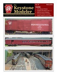
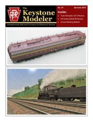
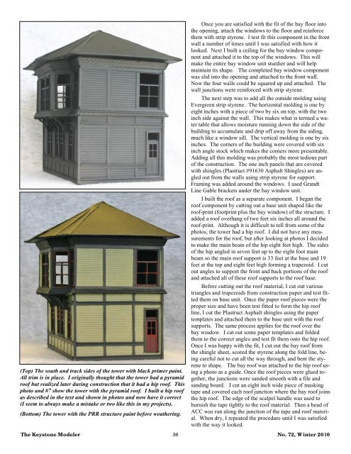
(Top) The south <strong>and</strong> track sides of the tower with black primer paint.<br />
All trim is in place. I originally thought that the tower had a pyramid<br />
roof but realized later during construction that it had a hip roof. This<br />
photo <strong>and</strong> #7 show the tower with the pyramid roof. I built a hip roof<br />
as described in the text <strong>and</strong> shown in photos <strong>and</strong> now have it correct<br />
(I seem to always make a mistake or two like this in my projects).<br />
(Bottom) The tower with the PRR structure paint before weathering.<br />
Once you are satisfied with the fit of the bay floor into<br />
the opening, attach the windows to the floor <strong>and</strong> reinforce<br />
them with strip styrene. I test fit this component in the front<br />
wall a number of times until I was satisfied with how it<br />
looked. Next I built a ceiling for the bay window component<br />
<strong>and</strong> attached it to the top of the windows. This will<br />
make the entire bay window unit sturdier <strong>and</strong> will help<br />
maintain its shape. The completed bay window component<br />
was slid into the opening <strong>and</strong> attached to the front wall.<br />
Now the four walls could be squared up <strong>and</strong> attached. The<br />
wall junctions were reinforced with strip styrene.<br />
The next step was to add all the outside molding using<br />
Evergreen strip styrene. The horizontal molding is one by<br />
eight inches with a piece of two by six on top, with the two<br />
inch side against the wall. This makes what is termed a water<br />
table that allows moisture running down the side of the<br />
building to accumulate <strong>and</strong> drip off away from the siding,<br />
much like a window sill. The vertical molding is one by six<br />
inches. The corners of the building were covered with six<br />
inch angle stock which makes the corners more presentable.<br />
Adding all this molding was probably the most tedious part<br />
of the construction. The one inch panels that are covered<br />
with shingles (Plastruct #91630 Asphalt Shingles) are angled<br />
out from the walls using strip styrene for support.<br />
Framing was added around the windows. I used Gr<strong>and</strong>t<br />
Line Gable brackets under the bay window unit.<br />
I built the roof as a separate component. I began the<br />
roof component by cutting out a base unit shaped like the<br />
roof-print (footprint plus the bay window) of the structure. I<br />
added a roof overhang of two feet six inches all around the<br />
roof-print. Although it is difficult to tell from some of the<br />
photos, the tower had a hip roof. I did not have any measurements<br />
for the roof, but after looking at photos I decided<br />
to make the main beam of the hip eight feet high. The sides<br />
of the hip angled in seven feet up to the eight foot main<br />
beam so the main roof support is 33 feet at the base <strong>and</strong> 19<br />
feet at the top <strong>and</strong> eight feet high forming a trapezoid. I cut<br />
out angles to support the front <strong>and</strong> back portions of the roof<br />
<strong>and</strong> attached all of these roof supports to the roof base.<br />
Before cutting out the roof material, I cut out various<br />
triangles <strong>and</strong> trapezoids from construction paper <strong>and</strong> test fitted<br />
them on base unit. Once the paper roof pieces were the<br />
proper size <strong>and</strong> have been test fitted to form the hip roof<br />
line, I cut the Plastruct Asphalt shingles using the paper<br />
templates <strong>and</strong> attached them to the base unit with the roof<br />
supports. The same process applies for the roof over the<br />
bay window. I cut out some paper templates <strong>and</strong> folded<br />
them to the correct angles <strong>and</strong> test fit them onto the hip roof.<br />
Once I was happy with the fit, I cut out the bay roof from<br />
the shingle sheet, scored the styrene along the fold line, being<br />
careful not to cut all the way through, <strong>and</strong> bent the styrene<br />
to shape. The bay roof was attached to the hip roof using<br />
a photo as a guide. Once the roof pieces were glued together,<br />
the junctions were s<strong>and</strong>ed smooth with a file <strong>and</strong><br />
s<strong>and</strong>ing board. I cut an eight inch wide piece of masking<br />
tape <strong>and</strong> covered each roof junction where the bay roof joins<br />
the hip roof. The edge of the scalpel h<strong>and</strong>le was used to<br />
burnish the tape tightly to the roof material. Then a bead of<br />
ACC was run along the junction of the tape <strong>and</strong> roof material.<br />
When dry, I repeated the procedure until I was satisfied<br />
with the way it looked.<br />
The Keystone Modeler 36 No. 72, <strong>Winter</strong> <strong>2010</strong>