Scanning Fabry-Perot Interferometers (High-Resolution ... - Thorlabs
Scanning Fabry-Perot Interferometers (High-Resolution ... - Thorlabs
Scanning Fabry-Perot Interferometers (High-Resolution ... - Thorlabs
- No tags were found...

Create successful ePaper yourself
Turn your PDF publications into a flip-book with our unique Google optimized e-Paper software.
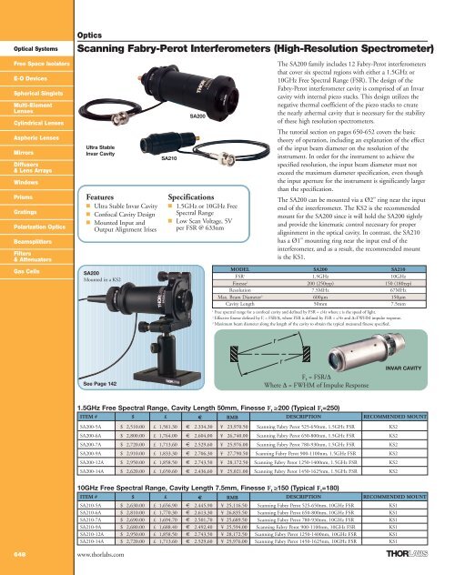
Optical SystemsOptics<strong>Scanning</strong> <strong>Fabry</strong>-<strong>Perot</strong> <strong>Interferometers</strong> (<strong>High</strong>-<strong>Resolution</strong> Spectrometer)Free Space IsolatorsE-O DevicesSpherical SingletsMulti-ElementLensesCylindrical LensesAspheric LensesMirrorsDiffusers& Lens ArraysWindowsPrismsGratingsPolarization OpticsBeamsplittersFilters& AttenuatorsGas CellsUltra StableInvar CavityFeatures■ Ultra Stable Invar Cavity■ Confocal Cavity Design■ Mounted Input andOutput Alignment IrisesSA200Mounted in a KS2SA210SA200Specifications■ 1.5GHz or 10GHz FreeSpectral Range■ Low Scan Voltage, 5Vper FSR @ 633nmThe SA200 family includes 12 <strong>Fabry</strong>-<strong>Perot</strong> interferometersthat cover six spectral regions with either a 1.5GHz or10GHz Free Spectral Range (FSR). The design of the<strong>Fabry</strong>-<strong>Perot</strong> interferometer cavity is comprised of an Invarcavity with internal piezo stacks. This design utilizes thenegative thermal coefficient of the piezo stacks to createthe nearly athermal cavity that is necessary for the stabilityof these high resolution spectrometers.The tutorial section on pages 650-652 covers the basictheory of operation, including an explanation of the effectof the input beam diameter on the resolution of theinstrument. In order for the instrument to achieve thespecified resolution, the input beam diameter must notexceed the maximum diameter specification, even thoughthe input aperture for the instrument is significantly largerthan the specification.The SA200 can be mounted via a Ø2" ring near the inputend of the interferometer. The KS2 is the recommendedmount for the SA200 since it will hold the SA200 tightlyand provide the kinematic control necessary for properaligninment in the optical cavity. In contrast, the SA210has a Ø1" mounting ring near the input end of theinterferometer, and as a result, the recommended mountis the KS1.MODEL SA200 SA210FSR 1 1.5GHz 10GHzFinesse 2 200 (250typ) 150 (180typ)<strong>Resolution</strong> 7.5MHz 67MHzMax. Beam Diameter 3 600µm 150µmCavity Length 50mm 7.5mm1Free spectral range for a confocal cavity and defined by FSR = c/4r where c is the speed of light.2Effective finesse defined by F t = FSR/∆, where FSR is defined by FSR = c/4r and ∆=FWHM impulse response.3Maximum beam diameter along the length of the cavity to obtain the typical measured finesse specified.See Page 142F t = FSR/∆Where ∆ = FWHM of Impulse ResponseINVAR CAVITY1.5GHz Free Spectral Range, Cavity Length 50mm, Finesse F t ≥200 (Typical F t =250)ITEM # $ £ € RMB DESCRIPTION RECOMMENDED MOUNTSA200-5A $ 2,510.00 £ 1,581.30 € 2.334,30 ¥ 23,970.50 <strong>Scanning</strong> <strong>Fabry</strong> <strong>Perot</strong> 525-650nm, 1.5GHz FSR KS2SA200-6A $ 2,800.00 £ 1,764.00 € 2.604,00 ¥ 26,740.00 <strong>Scanning</strong> <strong>Fabry</strong> <strong>Perot</strong> 650-800nm, 1.5GHz FSR KS2SA200-7A $ 2,720.00 £ 1,713.60 € 2.529,60 ¥ 25,976.00 <strong>Scanning</strong> <strong>Fabry</strong> <strong>Perot</strong> 780-930nm, 1.5GHz FSR KS2SA200-9A $ 2,910.00 £ 1,833.30 € 2.706,30 ¥ 27,790.50 <strong>Scanning</strong> <strong>Fabry</strong> <strong>Perot</strong> 900-1100nm, 1.5GHz FSR KS2SA200-12A $ 2,950.00 £ 1,858.50 € 2.743,50 ¥ 28,172.50 <strong>Scanning</strong> <strong>Fabry</strong> <strong>Perot</strong> 1250-1400nm, 1.5GHz FSR KS2SA200-14A $ 2,620.00 £ 1,650.60 € 2.436,60 ¥ 25,021.00 <strong>Scanning</strong> <strong>Fabry</strong> <strong>Perot</strong> 1450-1625nm, 1.5GHz FSR KS2648 www.thorlabs.com10GHz Free Spectral Range, Cavity Length 7.5mm, Finesse F t ≥150 (Typical F t =180)ITEM # $ £ € RMB DESCRIPTION RECOMMENDED MOUNTSA210-5A $ 2,630.00 £ 1,656.90 € 2.445,90 ¥ 25,116.50 <strong>Scanning</strong> <strong>Fabry</strong> <strong>Perot</strong> 525-650nm, 10GHz FSR KS1SA210-6A $ 2,810.00 £ 1,770.30 € 2.613,30 ¥ 26,835.50 <strong>Scanning</strong> <strong>Fabry</strong> <strong>Perot</strong> 650-800nm, 10GHz FSR KS1SA210-7A $ 2,690.00 £ 1,694.70 € 2.501,70 ¥ 25,689.50 <strong>Scanning</strong> <strong>Fabry</strong> <strong>Perot</strong> 780-930nm, 10GHz FSR KS1SA210-9A $ 2,680.00 £ 1,688.40 € 2.492,40 ¥ 25,594.00 <strong>Scanning</strong> <strong>Fabry</strong> <strong>Perot</strong> 900-1100nm, 10GHz FSR KS1SA210-12A $ 2,950.00 £ 1,858.50 € 2.743,50 ¥ 28,172.50 <strong>Scanning</strong> <strong>Fabry</strong> <strong>Perot</strong> 1250-1400nm, 10GHz FSR KS1SA210-14A $ 2,720.00 £ 1,713.60 € 2.529,60 ¥ 25,976.00 <strong>Scanning</strong> <strong>Fabry</strong> <strong>Perot</strong> 1450-1625nm, 10GHz FSR KS1
Optical SystemsFree Space IsolatorsE-O DevicesSpherical SingletsMulti-ElementLensesCylindrical LensesAspheric LensesMirrorsDiffusers& Lens ArraysOpticsSCANNING FABRY-PEROTINTERFEROMETERSDerivation of the Finesse:SA200-14A1.5 GHz <strong>Scanning</strong> <strong>Fabry</strong>-<strong>Perot</strong> InterferometerSA210-5A10 GHz <strong>Scanning</strong> <strong>Fabry</strong>-<strong>Perot</strong> InterferometerWindowsPrismsGratingsPolarization OpticsBeamsplittersFilters& AttenuatorsGas CellsThe core of Thorlab's scanning<strong>Fabry</strong>-<strong>Perot</strong> interferometers is anoptical cavity formed by two,nearly identical, spherical mirrorsseparated by their common radius ofcurvature as shown in Figure 1. Thisconfiguration is known as a modedegenerate,confocal cavity design, whichis generally referred to as a confocal <strong>Fabry</strong>-<strong>Perot</strong>. The cavity is mode degeneratebecause the frequency of certain axial andtransverse cavity modes are the same(degenerate). This degeneracy greatlyFigure 1Schematic drawing of mirrors of radius r separatedby r to within a few microns.simplifies the alignment of the instrumentby eliminating the need to carefully modematch the input to the cavity.The inner concave surface of each mirrorhas a high reflectivity coating, while theouter convex surface has a broadbandantireflection coating. The curvature onthe outer surface (which matches that ofthe inner surface) eliminates lensingeffects. To illustrate operation of theconfocal cavity, it is useful to follow a rayas it enters the cavity off-axis and travelsone round trip through the cavity. Asseen in Figure 2, the beam enters thecavity at a height H. A portion of the rayfollows the path numbered 1, 2, 3, and 4;it is then reflected onto path 1 again. Thedotted lines exterior to the cavity in Figure2 represent the portion of the ray that istransmitted through the cavity mirrorswhen the cavity is resonant with the input(i.e. when the round trip distance equalsmλ, where m is an integer, and λ is thewavelength of the input radiation). Theapproximate optical path length (L) of oneround trip through the cavity can beexpressed asL=4r (1)when H does not equal zero.Free Spectral Range (FSR)A plano-plano <strong>Fabry</strong> <strong>Perot</strong> cavity with around trip distance of 2d has an FSR thatis given by FSR = c/2d, where d is themirror separation and c the speed of lightin air. A confocal cavity with the longertotal round trip path length of 4r has aneffective FSR, that is approximately half ofthe FSR for a plano-plano cavity with0
OpticsOptical SystemsFinesse & <strong>Resolution</strong> of a Confocal CavityFor a <strong>Fabry</strong>-<strong>Perot</strong> cavity, the finesse is ameasure of the interferometer’s ability toresolve closely spaced spectral features.The minimum resolvable frequencyincrement of an interferometer is based onthe Taylor Criteria, which stipulates thatfor two closely spaced lines of equalintensity to be resolved, the sum of thetwo individual lines at the midway pointcan at most be equal to the intensity ofone of the original lines (see Figure 3).Figure 3When two equal Gaussian lineshapes just meetthe Taylor criteria for being resolvable, theyare separated by their common FWHM (∆)as shown in the plot.The FSR and the FWHM of arepresentative lineshape are shown inFigures 4 and 5, respectively. An Ft of 294is measured using a DFB laser with alinewidth that cannot be consideredinfinitely small in comparison to theresolution of the cavity. Therefore, thetrue Ft is about 320, assuming a 2MHzlaser linewidth.A measured finesse has a number ofcontributing factors: the mirror reflectivityfinesse F r , the mirror surface qualityfinesse F q , and the finesse due to theillumination conditions (beam alignmentand diameter) of the mirrors F i . Therefore,the total inverse of the finesse of a systemcan be written as1/F t = [(1/F R ) 2 + (1/F q ) 2 + (1/F i ) 2 ] 1/2 , (4)where the effective mirror reflectivityfinesse is given byF R = πR 1/2 /(1-R). (5)here, R is the mirror reflectivity.While the definition for the reflectivityfinesse is ambiguous in the literature,Eq. (5) is presented as an “effective”finesse that is defined by Eq. (3) when theother contributing factors are negligible.For the SA200 series, the reflectivityfinesse dominates when operating withproper illumination (Johnson, J.R. “A<strong>High</strong> <strong>Resolution</strong> <strong>Scanning</strong> ConfocalInterferometer” Appl. Opt. 7, 1061-1072,1968.)The values predicted by Eq. (5) agree towithin a few percent of the measuredvalues. Many authors use a formula thatpredicts a reflectivity finesse that is less bya factor of 2. However, Johnson pointsout that “the apparent loss in finesse ... isfully restored when the full output of aproperly illuminated cavity is observed.”Therefore, the finesse given by Eq. (5)is realized.Using Eq. (5), the reflective coatings inthe SA200 series interferometers havebeen designed so that the minimum FR isbetter than 1.5 times the minimumspecified finesse across their entireoperating wavelength range for eachmodel (see the table on the product page).This fixes the first term of Eq. (4).Free Space IsolatorsE-O DevicesSpherical SingletsMulti-ElementLensesCylindrical LensesAspheric LensesMirrorsDiffusers& Lens ArraysWindowsPrismsGratingsPolarization OpticsBeamsplittersFilters& AttenuatorsGas CellsThe total finesse of an interferometer isdefined as the ratio of the FSR to ∆ where∆ is the FWHM of the impulse responsefunction for the system. As can be seen inFigure 3, two lines separated by ∆ are justresolvable according to the Taylor criteria.Therefore, ∆ is also used as a measure ofthe resolution of the system.The equation for the total finesse is givenbyPeaks∆T= 20ms2V/div 2.5ms/divFigure 4The plot to the left shows an FSR Plot,using a 1550nm DFB laser (PRO8000series, page 433). Using the modelSA200-14A, 1.5GHz interferometer, thisplot is used to calibrate the time-base ofthe oscilloscope. Knowing that the FSRof the interferometer is 1.5GHz, thecalibration factor is found by setting1.5GHz = 20ms (75MHz/ms), thedistance between the two peaks.F t = FSR/∆. (3)Note, during the manufacturing of theSA200 series interferometers, F t ismaximized in order to adjust the cavitylength to the confocal condition bymaximizing its value. This methodprovides a very precise means for settingthe required length of the cavity to betterthan λ.Figure 5This plot shows a close-up of the actual signalof the laser, which results from the convolutionof the laser linewidth and finesse of the cavity;with the oscilloscope timebase calibrated fromFigure 4, at 75MHz/ms, we determine theFWHM for the interferometer to be 0.068msx 75MHz/ms for a FWHM of 5.1MHz. Thisprovides a lower limit for the finesse of 294.2V/div 50µs/divFWHM∆T= 68µswww.thorlabs.com651
Optical SystemsOptics<strong>Scanning</strong> <strong>Fabry</strong>-<strong>Perot</strong> <strong>Interferometers</strong>… continuedFree Space IsolatorsE-O DevicesSpherical SingletsMulti-ElementLensesCylindrical LensesAspheric LensesMirrorsDiffusers& Lens ArraysWindowsPrismsGratingsPolarization OpticsBeamsplittersFilters& AttenuatorsGas CellsThe second term in Eq. (4) involves F q ,which accounts F q , accounts for mirrorirregularities that cause a symmetricbroadening of the lineshape. The effectof these irregularities is a random positiondependentpath length difference thatblurs the lineshape. The manufacturingprocess that is used to produce the cavitymirrors ensures that the contribution fromF q is negligible in comparison to ourspecified total finesse for each model.The final term in Eq. (4), which dealswith the illumination finesse F i , willreduce the resolution as the beam diameteris increased or as the input beam is offset.When the finesse is limited by the F i term,the measured lineshape will appearasymmetric. The asymmetry is due to thepath length difference between an on-axisbeam and an off-axis beam, resulting indifferent mirror spacings to satisfy themaximum transmission criteria. Theapproximate decrease in path length for abeam at a distance H off axis is given bythe second term in Eq. (2).To quantify the effects of the variable pathlength on F i , consider an idealmonochromatic input, a delta function inwavelength with unit amplitude, enteringthe FP cavity coaxial to the optic axis andhaving a beam radius a. The light enteringthe interferometer at H=+e, where e isinfinitesimally small but not zero, willnegligibly contribute to a deviation in thetransmitted spectrum. Light entering thecavity at H=+a will cause a shift in thetransmitted output spectrum, since theoptical path length of the cavity will be lessby an approximate distance of a 4 /4r 3 .Assuming the input beam has a uniformintensity distribution, the transmittedspectrum will appear uniform in intensityFigure 6and broader due to the shifts in the opticalpath length. As a result, the wavelengthinput delta function will produce anoutput peak with a FWHM of H 4 /4r 3 .Assuming that only F i contributessignificantly to the total finesse, then Eq.(3) can be used to calculate F i for theidealized input beam:F i = FSR/FWHM.r=7.5mmSubstituting λ/4 for the FSR, and (H 4 /4r 3 )for FWHM, yieldsF i = (λ/4)/(H 4 /4r 3 ) (6)The λ/4 substitution for the FSR isunderstood by considering that the cavityexpands by λ/4 to change from onelongitudinal mode to the next. For aninput beam with a real spectraldistribution, the effect of the shift will be acontinuous series of shifted lineshapes.It should be noted that the shift is alwaysin one direction, leading to a broadened orassymmetric lineshape due to the over-sizedor misaligned beam.Now, using Eq. (4), the total finesse whichincludes significant contributions fromboth F R and F i can be found (Note: F q isstill considered to have a negligible effecton F t ):F t = [ (1/F R ) 2 + (1/F i ) 2 ] -1/2 . (7)Replacing F i yields:r=50mmThis plot shows Ft(H), for the three different <strong>Fabry</strong>-<strong>Perot</strong> <strong>Interferometers</strong>, the red curve is for ther=3mm, the yellow curve is for the r=7.5mm, and the blue curve is for the r=50mm cavity.F t (H, R) = [ (1/F R ) 2 + (H 4 /λr 3 ) 2 ] -1/2 . (8)Eq. (8) is used to provide an estimate(albeit an overestimate) of effects of beamdiameter effects on the total finesse of a<strong>Fabry</strong>-<strong>Perot</strong> Interferometer. Figure 6provides a plot of Eq. 8 for the two cavitydesigns offered (r=50mm and r=7.5mm).The traces in the plot were made with theassumption that the reflectivity finesse isequal to 300, which is the typical valueobtained for mirrors used in the SA200series interferometers. ■Beam Expander/ReducerExpand or reduce thediameter of a beam withdiffraction-limitedperformance.See Page 662652 www.thorlabs.com