Ultrasonic Measurement prosonic - VDT Industrie
Ultrasonic Measurement prosonic - VDT Industrie
Ultrasonic Measurement prosonic - VDT Industrie

You also want an ePaper? Increase the reach of your titles
YUMPU automatically turns print PDFs into web optimized ePapers that Google loves.
Technical<br />
Information<br />
TI 013F/24/ae<br />
FDU 80<br />
FDU 83<br />
FDU 85<br />
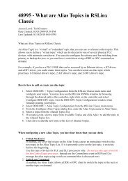
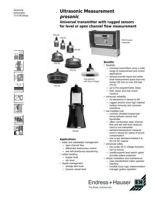
<strong>Ultrasonic</strong> <strong>Measurement</strong><br />
<strong>prosonic</strong><br />
Universal transmitter with rugged sensors<br />
for level or open channel flow measurement<br />
FDU 81<br />
FDU 84<br />
FDU 82<br />
FDU 86<br />
FDU 80F/81F<br />
with Slip-on Flange<br />
Applications<br />
• water and wastewater management<br />
– open channel flow<br />
– differential level/screen control<br />
– wet well level/pump sequencing<br />
• solids handling<br />
– hopper level<br />
– silo level<br />
• liquids management<br />
– storage tank level<br />
– process vessel level<br />
The Power of Know-how<br />
FMU Prosonic<br />
Transmiiter<br />
Benefits<br />
• flexibility<br />
– universal transmitters cover a wide<br />
range of measurement and control<br />
applications<br />
– sensors provide liquid and solids<br />
level measurement spans from two<br />
inches (50 mm) to over 230 feet<br />
(70 m)<br />
– up to five programmable relays<br />
– field, panel, and rack mount<br />
versions<br />
• enhanced reliability<br />
– no electronics in sensor to fail<br />
– rugged sensors have high material<br />
buildup immunity and corrosion<br />
resistance<br />
• low installed cost<br />
– common shielded twisted-pair<br />
wiring between sensor and<br />
transmitter<br />
– offers combination open channel<br />
flow and wet well level measurement<br />
in one transmitter<br />
– standard temperature measurement<br />
in sensor for speed of sound<br />
compensation<br />
– one or two standard isolated 4 to<br />
20 mA DC outputs<br />
• enhanced safety<br />
– low (under 50 V) voltage transmission<br />
to sensor<br />
– overfill/underfill level switch option<br />
provides added protection<br />
• simple installation and maintenance<br />
– uses standardized matrix operator<br />
interface<br />
– invisible fuzzy logic implementation<br />
manager guides operation
General Information<br />
Provides 150 programmed flow curves<br />
Differential level measurement and screen control<br />
Level measurement and pump sequencing<br />
of up to five pumps<br />
Prosonic is designed specifically for<br />
customers who need to make reliable<br />
ultrasonic level or open channel flow<br />
measurement. Prosonic is based on the<br />
ultrasonic theory, which states that sound<br />
travels through space at known rates<br />
depending on the density and temperature<br />
of the medium. <strong>Ultrasonic</strong> level<br />
technology measures the time it takes for<br />
a burst of sound to travel from a sensor<br />
to a reflective surface and back. It then<br />
converts that information into a level<br />
measurement. This noncontact approach<br />
is ideal for many industrial<br />
applications where corrosive conditions,<br />
changing product characteristics, and<br />
other factors make contacting level<br />
measurement devices less reliable.<br />
Predicting all the conditions that affect an<br />
ultrasonic level measurement system<br />
often can be a difficult task. Applications<br />
that appear to be simple may become<br />
very challenging due to filling noise,<br />
nuisance reflections, or variable material<br />
profiles. Even more challenging are<br />
applications where these and other<br />
interfering conditions are changing<br />
constantly.<br />
Prosonic brings many reliable level<br />
measurement and operating capabilities<br />
closer to the user. A new generation of<br />
ultrasonic sensors provides high sensitivity,<br />
rugged construction, and resistance<br />
to corrosive coatings. A fuzzy logic<br />
implementation manager in the transmitter<br />
smoothly combines many sophisticated<br />
signal processing techniques<br />
through the Endress+Hauser operator<br />
interface. The user can set up a<br />
Prosonic application by entering a few<br />
parameters describing individual<br />
measurement needs. As conditions<br />
change, Prosonic adapts to provide<br />
reliable level information. Prosonic also<br />
provides HART ® or Rackbus communication<br />
allowing an operator to remotely<br />
interface with the measurement system<br />
anywhere on its 4 to 20 mA loop with a<br />
handheld communicator or laptop<br />
computer.<br />
The Prosonic family is designed to fulfill<br />
many measurement and control needs.<br />
Prosonic addresses water/wastewater<br />
management, solids handling, and<br />
process industry liquid level measurement<br />
requirements.<br />
2<br />
In the water/wastewater management<br />
industry, Prosonic measures open<br />
channel flow, differential level across<br />
screens, and wet well level. It provides<br />
sampler, differential screen and pump<br />
sequencing control. Prosonic offers<br />
accurate measurements of hopper level<br />
and bulk storage inventory. In the field of<br />
liquids management, Prosonic provides<br />
level measurement in a wide variety of<br />
process and storage vessels. The dualchannel<br />
Prosonic can measure level in<br />
any two applications simultaneously - for<br />
example, open channel flow and long<br />
range liquid level, or short range liquid<br />
and long range solids level.<br />
Endress+Hauser offers eight different<br />
sensors with characteristics suited for<br />
various ranges and measurement<br />
conditions. Prosonic can measure<br />
material spans from two inches to 147<br />
feet with a resolution of 1/32” (1 mm) or<br />
0.1% of span (which ever is greater).<br />
Users can mount the sensor up to 1,000<br />
feet (300 m) from its transmitter using<br />
industry standard shielded twisted-pair<br />
wire. HART ® technology enables users to<br />
interact with the measuring system at<br />
any point in the 4 to 20 mA loop.<br />
The dual-channel Prosonic, FMU 862,<br />
provides point and continuous, long and<br />
short range, and differential level<br />
measurement. The FMU 862 also can<br />
support a single open channel flow<br />
measurement. The FMU 862 is designed<br />
for use with single channel level in solids<br />
or liquids environments. The FMU 861 is<br />
designed to make open channel flow<br />
measurements. All systems have three<br />
or five relay outputs for limit signals,<br />
totalizers, and printers.<br />
Certified quality<br />
Development, production, and documentation<br />
are all critical factors when<br />
evaluating the quality of Prosonic.<br />
Endress+Hauser is an approved company<br />
which fulfills all the quality standards<br />
set by ISO 9001.
Features and Benefits<br />
Model Features<br />
FMU 860 Single channel level<br />
FMU 861 Single channel open channel flow<br />
FMU 862 Dual channel for differential,<br />
averaging, and dual level<br />
measurements. Single channel<br />
for open channel flow.<br />
Options LCD backlighting, Rackbus<br />
or HART ® protocol, 3 or 5 output<br />
relays, overfill / underfill protection.<br />
Several factors can distort an ultrasonic<br />
measurement. By eliminating multiple<br />
reflections, unwanted echoes, effects of<br />
sensor coatings, and unwanted noise,<br />
Prosonic provides very accurate and<br />
dependable measurements.<br />
The sensor, connecting cable, and<br />
transmitter all contribute to reliable<br />
ultrasonic level measurement, economical<br />
installation costs, ease of operation,<br />
and safe plant operation.<br />
Sensors<br />
Prosonic draws form a family of sensors<br />
providing the highest efficiency and<br />
resistance to material buildup available.<br />
The greater efficiency of the FDU 8X<br />
sensor family provides reliable measurement<br />
of level even with substantial<br />
material buildup or dripping liquids. The<br />
sensor can even be submerged in liquids<br />
without damage. Other ultrasonic level<br />
suppliers may provide thin membrane<br />
ultrasonic sensors that, due to weak<br />
acoustic power and lack of protection,<br />
are easily compromised by buildup and<br />
corrosion.<br />
The FDU 8X sensor design reduces side<br />
lobes, which are responsible for many of<br />
the unwanted reflections found in<br />
sensors offered by other manufacturers.<br />
This sensor design enhances the<br />
reliability of the system by reducing the<br />
number of unwanted reflections the<br />
transmitter must filter out. The integral<br />
temperature sensor is a standard<br />
Prosonic offering; it gives the user<br />
speed-of-sound compensation without<br />
requiring an optional temperature sensor.<br />
Because Prosonic has no electronics in<br />
the sensor, less of the system is exposed<br />
to hostile conditions in the field.<br />
PROSONIC<br />
FMU 860<br />
1<br />
2 V H<br />
3<br />
4<br />
5<br />
E<br />
3<br />
E+H operator interface<br />
Supports FDU 8X<br />
sensors<br />
Separate wiring<br />
compartment<br />
Three or five 4 amp<br />
SPDT relays<br />
Relays fully<br />
programmable<br />
High/low level switch<br />
option<br />
HART communication<br />
option<br />
No electronics at<br />
sensor. Submersible<br />
design. Low voltage<br />
transmission.<br />
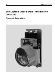
Cable Connections<br />
Prosonic sensors can be mounted up to<br />
1,000 feet (300 m) away from the<br />
transmitter using common shielded<br />
twisted-pair wiring. It may be possible to<br />
install Prosonic using existing wiring.<br />
E<br />
B<br />
F<br />
B = Blocking distance<br />
NOTE: Blocking distance is the area directly<br />
below the sensor in which level cannot be<br />
sensed. Each time the sensor pulses, it must<br />
stop ringing before it can listen for a returned<br />
signal. This waiting period translates into a<br />
specific distance which is inherent to the sensor<br />
model specified.<br />
D = Distance from sensor to surface<br />
of fill material<br />
L = Level in vessel<br />
F = Maximum fill height (100% full)<br />
E = Zero point of measurement<br />
(0%, empty)<br />
Blocking Distance (B)<br />
FDU 80 / 80 F 12” (0.3 m)<br />
FDU 81 / 81 F 20” (0.5 m)<br />
FDU 82 29” (0.8 m)<br />
FDU 83 36” (1.0 m)<br />
FDU 84 29” (0.8 m)<br />
FDU 85 29” (0.8 m)<br />
FDU 86 62” (1.6 m)<br />
D<br />
L<br />
FMU
V0<br />
V1<br />
V2<br />
V3<br />
H0<br />
Measured<br />
Value<br />
Relay<br />
Selection<br />
Linearization<br />
Fixed Target<br />
Suppression<br />
Preset Q/h<br />
Characteristic<br />
Curves:<br />
Right-angled<br />
Weir<br />
Trapezoidal Weir<br />
Triangular Weir<br />
Venturi Channel<br />
The unique design of the FMU 8X<br />
sensors requires less than 50 volts to<br />
operate. Most other industrial ultrasonic<br />
sensors available today require up to<br />
1000 volts, requiring coaxial cable to<br />
safely convey this high voltage in the<br />
field. Prosonic offers lower installed<br />
costs because shielded twisted-pair<br />
wiring is less expensive than coaxial<br />
cable.<br />
Transmitter<br />
The FMU 86X transmitters offer signal<br />
processing capabilities and ease of<br />
operation unmatched by suppliers of<br />
other ultrasonic measurement systems.<br />
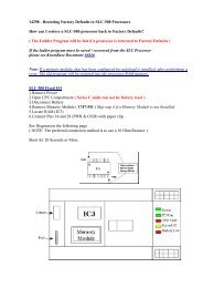
Endress+Hauser Operator<br />
Interface<br />
Prosonic offers an operator interface that<br />
is becoming the standard for the industry.<br />
The Endress+Hauser operator interface<br />
is a matrix array offering access to<br />
information and parameters common to<br />
hundreds of thousands of measurement<br />
systems installed worldwide. Users<br />
responsible for installing or interacting<br />
with these instruments do not have to<br />
learn another new operator interface in<br />
order to work with the Prosonic.<br />
4<br />
H1<br />
Empty<br />
Calibration<br />
Relay<br />
Function<br />
Preset<br />
Height<br />
Echo<br />
Attentuation<br />
H2<br />
Full<br />
Calibration<br />
Switch-0n<br />
Point<br />
Q/h Character<br />
Curve<br />
S/N<br />
Factor<br />
H3<br />
Application<br />
Switch-Off<br />
Point<br />
Liquid<br />
Level<br />
Warning /<br />
Fault<br />
Fine-grained<br />
Bulk Solids<br />
Coarse-grained<br />
Bulk Solids<br />
Rapid Level<br />
Changes<br />
H4<br />
Sensor<br />
Type<br />
Pump<br />
Control<br />
Volume<br />
Output<br />
With Fault<br />
Prosonic has five level measurement<br />
operating modes to make initial setup<br />
easier for the end user: standard,<br />
liquids, liquids with rapid level changes,<br />
fine-grained bulk solids, coarse bulk<br />
solids, and solids with rapid level<br />
changes. In addition to the five operating<br />
modes, Prosonic includes 150 preset<br />
open channel calibration curves designed<br />
to mate with your particular weir<br />
or channel.<br />
Fuzzy Logic<br />
Through the Endress+Hauser operator<br />
interface and invisible to the user is a<br />
management system that processes a<br />
collection of patented or proprietary<br />
signal processing algorithms. The user<br />
can enter one or two values through the<br />
operator interface defining the type of<br />
level or open channel flow application<br />
installed. The fuzzy logic implementation<br />
manager selects and blends the signal<br />
processing algorithms best suited to the<br />
application. Users can set up most<br />
applications without the need for factory<br />
or other trained personnel. Selected<br />
signal processing algorithms are<br />
described in the following sections.
Time<br />
Signal<br />
Time Dependent Threshold<br />
The time dependent threshold (TDT)<br />
detects echoes above a set level by<br />
gauging a collection of echoes (and<br />
noise) returned from various distances.<br />
This collection of echoes often is referred<br />
to as an envelope curve. Typically, the<br />
TDT is set higher for echoes closer to the<br />
sensor and lower for echoes farther away<br />
so that much of the unwanted noise is<br />
not detected. Because the TDT is fixed<br />
at the beginning and end of the envelope<br />
curve, it is not always able to respond to<br />
changes within the envelope curve from<br />
filling operations, material buildup, and<br />
dust formation. For many applications, it<br />
is implemented successfully.<br />
Floating Average Curve<br />
The floating average curve (FAC), a<br />
dynamic adaptation of the TDT, can<br />
respond to level changes that the TDT<br />
cannot detect. Like the TDT, the FAC<br />
filters out noise and unwanted echoes.<br />
However, the FAC is generated from a<br />
running average of envelope curves,<br />
enabling Prosonic to detect true level<br />
echoes even when acoustic conditions<br />
vary greatly. This method enables<br />
Prosonic to respond to changes within<br />
the envelope curve that the TDT is<br />
unable to manage.<br />
Tank Mapping<br />
Tank mapping is a patented technique<br />
that digitizes and eliminates unwanted<br />
echoes from fixed reflective surfaces<br />
inside a silo or vessel (see illustration<br />
left). Via the Endress+Hauser operator<br />
interface, users can set the TDT or FAC<br />
to ignore unwanted echoes when the silo<br />
or vessel is empty. When the material<br />
level moves up and down past the source<br />
of unwanted echoes, the echo representing<br />
the level is tracked, rather than the<br />
unwanted echoes.<br />
First Echo Factor<br />
Sometimes the echoes detected by the<br />
TDT or FAC do not represent the true<br />
level. Echoes from the walls of a silo or<br />
hopper may be as significant as the<br />
direct echoes from the material surface.<br />
The relative sizes of these echoes may<br />
vary, so an algorithm is used to decide<br />
which echo is correct. This algorithm<br />
calculates an effective first echo factor<br />
that adjusts to the amplitude of the<br />
largest echo and changes with variations<br />
in the strength of the echoes. A large<br />
echo amplitude results in a large first<br />
echo factor and a small echo amplitude<br />
results in a small factor.<br />
5<br />
The algorithm is set up with the appropriate<br />
first echo factors and first echo<br />
switch-off points with each operating<br />
mode. The effective first echo factor is<br />
formed from these values and the echo<br />
attenuation. If a smaller, earlier echo<br />
exceeds an effective first echo factor, it is<br />
considered to be the one representing<br />
true level.<br />
Zone Evaluation<br />
Bulk materials in silos or hoppers often<br />
form multiple reflective surfaces. These<br />
diffused echoes representing several<br />
levels may cause a constantly changing<br />
display as the echo pattern changes.<br />
Zone evaluation is a mathematical<br />
smoothing of the envelope curve melding<br />
the diffused echoes into one echo that<br />
more clearly represents the level<br />
measurement value.<br />
Fuzz Filter<br />
The fuzz filter operates like a register that<br />
can have 0, 2, 4, 8, or 16 storage<br />
locations. With every ultrasonic pulse,<br />
the fuzz filter stores a new measured<br />
value. The displayed value is calculated<br />
from the average of all the values. When<br />
all storage locations are full, the oldest<br />
value is removed and replaced by the<br />
next value, and so on. This process<br />
rapidly produces a stable displayed<br />
value. Jitter during constant level<br />
conditions is eliminated, and runoff after<br />
filling or emptying the vessel is prevented.<br />
Agitator Filter<br />
The movement of agitator blades in the<br />
path of the ultrasonic beam can cause<br />
significant undesired reflections. The<br />
agitator filter algorithm determines the<br />
reflective pattern of the agitator blade<br />
and eliminates it from further signal<br />
processing.
Sensor Selection<br />
The most crucial aspect of the measuring<br />
process is sensor selection and installation.<br />
Preliminary selection of the sensor<br />
can be made by comparing your needs<br />
to the sensor specifications. When<br />
making a final decision, use the table<br />
(right) to choose the correct sensor.<br />
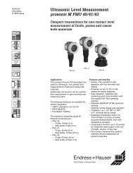
The diagram below defines the effect<br />
echo attenuation has on the sensor’s<br />
measurement range. The ideal echo<br />
attenuation curves are shown for each<br />
sensor. Also shown is the echo attenuation<br />
detection limit (120dB), the lowest<br />
echo attenuation detectable by the<br />
Prosonic transmitter. To account for<br />
extraneous tank noise, a 20 dB noise<br />
buffer is added, which sets a practical<br />
echo attenuation detection limit (100 dB).<br />
A number of echo attenuation sources<br />
that affect proper sensor selection are<br />
shown in the table at the right. Add the<br />
echo attenuation sources that are<br />
present in your application. Use your<br />
estimated attenuation total and the<br />
Range diagram below to determine each<br />
sensor’s practical measurement range.<br />
Echo attenuation as a<br />
function of range for<br />
various sensors (ideal<br />
reflection and atmospheric<br />
conditions)<br />
Sensors mounted in nozzles<br />
generate a background noise<br />
of 20 dB which decreases<br />
with measuring range - at<br />
13 feet (4 m) it falls to 0 dB.<br />
Check the factors affecting<br />
your measurement from the<br />
table above. Add up their<br />
attenuation values. Take this<br />
sum and find the point where<br />
it intersects with the range<br />
limit of the sensor you are<br />
using. This gives the<br />
maximum measuring range of<br />
that sensor.<br />
Measuring Range (ft.)<br />
230<br />
Echo Attenuation Sources dB<br />
Temperature difference<br />
Up to 68°F (20°C) 0<br />
Up to 104°F (40°C) 5 to 10<br />
Up to 140°F (60°C) 10 to 20<br />
Fill Stream<br />
Out of detection range 0<br />
Small quantities in detection<br />
range 5 to 10<br />
Large quantities in detection<br />
range 10 to 20<br />
Dust<br />
No dust development 0<br />
Little dust development 5<br />
Heavy dust development 5 to 10<br />
Solid Material Surface<br />
Hard, rough 20<br />
Soft (e.g., peat, dust covered<br />
clinker) 20 to 40<br />
Liquid Surface<br />
Calm 0<br />
Wavy 5 to 10<br />
Very turbulent (e.g. agitator) 10 to 20<br />
Foam CF<br />
Pressure<br />
14 to 30 psi 0<br />
Partial vacuum CF<br />
Steam CF<br />
Liquids / Solids Extended<br />
Tempeature Range (-40°F)<br />
signal reduction (add to<br />
attenuation dB for<br />
temperatures from<br />
-4° to -40°F<br />
FDU 80 / FDU 81 4<br />
FDU 82 / FDU 83 15<br />
FDU 84 15<br />
FDU 85 20<br />
Example For Calculating the Range (Liquid Tank)<br />
FACTORS ATTENUATION<br />
Temperature difference in tank, maximum 104°F (40°C) 10 dB<br />
Small fill stream quantities in detection range 10 dB<br />
Liquid surface is strongly turbulent 20 dB<br />
Sum of Attenuation Values 40 dB<br />
Under the above conditions, the range is approximately 23 feet (7 m) with the FDU 81<br />
sensor.<br />
6<br />
150<br />
130<br />
100<br />
60<br />
FDU 86<br />
FDU 85<br />
FDU 83<br />
FDU 82<br />
30<br />
23<br />
16<br />
0<br />
FDU 81/81F<br />
FDU 80/80F<br />
0 20 40 60<br />
Attenuation (dB)<br />
80 100 110
Sensor Location<br />
For best performance and maximum<br />
range, the selected sensor should be<br />
positioned vertically at the top of the<br />
vessel. It should be in a location that<br />
maximizes its returned echo signal and<br />
minimizes vessel obstructions in its line<br />
of sight. Although an individual sensor<br />
has a constant, definable output beam,<br />
the more important consideration is the<br />
line-of-sight reflected echo.<br />
Minimizing vessel obstructions in the line<br />
of sight is accomplished by considering<br />
the geometry of both the vessel and the<br />
7<br />
resulting reflected echoes. On vessels<br />
that have coned bottoms, or dished<br />
(round) tops, positioning the sensor away<br />
from the vessel center is recommended<br />
to eliminate echo travel paths not related<br />
to the level.<br />
Maximizing the returned level echo is<br />
generally accomplished by avoiding<br />
sensor mounts that either sight into the<br />
fill stream or position the sensor so that a<br />
large part of its output beam is lost into<br />
the vessel wall (see illustration at left).
Sensor Installation<br />
Prosonic sensors are provided with 1”<br />
NPT fittings for mounting flexibility. The<br />
FDU 80/81F sensors may also be<br />
installed with a slip-on flange.<br />
For optimum performance, the sensor<br />
should be installed so that its lower edge<br />
is below the top of the tank or silo. This<br />
can be done if the maximum level does<br />
not enter into the blocking distance (blind<br />
space) of the sensor. See illustration<br />
below.<br />
Flange mounting<br />
Pipe well mounting is used when the<br />
material high level is high enough that<br />
the sensor must be moved to allow for<br />
the blocking distance.<br />
Inner Edge<br />
45° x .08" (2 mm)<br />
D<br />
L<br />
Pipe well mounting<br />
Sensor positioner mounting, below,<br />
depicts how the sensor can be installed<br />
in the best position with respect to the<br />
measured material. A sensor positioner<br />
can be used to install a sensor in a tank<br />
that has an opening smaller than the<br />
sensor’s diameter.<br />
Sensor positioner mounting<br />
8<br />
FDU 80F<br />
FDU 81F<br />
Sensor D L<br />
FDU 80 / 80 F 3.9”
Technical Data<br />
Transmitter FMU 86X<br />
Enclosure Field, NEMA 4X (IP 65), corrosion-resistant reinforced plastic with<br />
nine punch-out conduit entries. Optional panel mount (144 x 144 mm)<br />
or rack mount (19”, 21 HP); both include keypad and display.<br />
Display 4-1/2 digit LCD with vertical and horizontal matrix position display<br />
and bar graph (%). Optional backlit matrix display.<br />
Communication Plug-in options supporting INTENSOR or HART serial communication<br />
via the 4 to 20 mA loop or RS 485 interface (DMS ready)<br />
Sensor Input One or two (FMU 862 only) sensor channels of any combination<br />
Weight Field mounted, 5.7 lbs (2.6 kg). Panel, 2.2 lbs (1 kg). Rack, 2.8 lbs<br />
(1.3 kg).<br />
Electrical Classification General purpose<br />
Resolution 0.03” (1 mm) or 0.1% of measuring span (which ever is greater)<br />
Power Input 90 to 146 VAC, 50/60 Hz; 180 to 276 VAC, 50/60 Hz; 20 to 30 VDC<br />
EMI / RFI Effects 1% for maximum measuring span at 10 V/m (10 kHz to 1 GHz) to<br />
NAMUR, IEC 801-3<br />
Overfill/Underfill Input Support connections to external voltage free make-or-break contacts<br />
or PNP switches<br />
Power Consumption 15 VA maximum<br />
Operating Temperature -4°F to + 140°F (-20° to +60°C)<br />
Storage Temperature -24°F to + 176°F (-40° to + 80°C)<br />
Humidity 95% average annual humidity<br />
Drift Temperature, negligible; load, negligible<br />
Shock Resistance 2g (10 to 55 Hz) and 15g for 11 ms per DIN40 040, type W<br />
Relay Outputs 3 or 5 SPDT, 4A at 250 VAC programmable relays including<br />
fault indication, limit switches, totalizer driver (FMU 861 and 862 only),<br />
sampler activation (FMU 861 and 862 only)<br />
Analog Outputs 1 or 2 (FMU 862 only) isolated 4 to 20 mA @ 600 Ohms maximum.<br />
Output current limit, 24 mADC<br />
Indicators Yellow LED for each relay, lighting during de-energized state; green<br />
LED indicating proper operation<br />
Totalizer Optional 6-digit (non-resettable, FMU 861 and 862 only)<br />
Keypad Interface 6 tactile feedback keys to access operator matrix. V and H keys for<br />
vertical and horizontal movement. Other keys for data entry.<br />
Recommended Cable 18-AWG, two-conductor with maximum 25 Ohms and 60 nF per<br />
conductor, maximum 1000 feet<br />
Optional Accessories FAU 40 sensor positioner, all-weather cover, pipe-mount kit.<br />
Dimensions Refer to diagram below<br />
Mounting<br />
Hole (4)<br />
7.9"<br />
(Mtg.)<br />
Knock-out<br />
Conduit<br />
Entry (9)<br />
9<br />
PROSONIC<br />
FMU 860<br />
10.85"<br />
(Mtg.)<br />
11.5"<br />
1<br />
2<br />
3<br />
4<br />
5<br />
V H<br />
E<br />
10"<br />
4.17"
Technical Data (con’t)<br />
4.7" FDU<br />
80F / 81F<br />
3.1"<br />
dia.<br />
5.4"<br />
17.7"<br />
4.8"<br />
5.2"<br />
1.18"<br />
3.4"<br />
dia.<br />
FDU<br />
80 / 81<br />
2.76"<br />
dia.<br />
16.4 ft. cable<br />
2-wire with<br />
shield<br />
FDU 82<br />
3.86"<br />
dia.<br />
16.4 ft. cable<br />
2-wire with<br />
shield<br />
FDU 83<br />
7.4" dia.<br />
FDU 86<br />
7.8" dia.<br />
16.4 ft. cable<br />
2-wire with<br />
shield<br />
16.4 ft. cable<br />
3-wire with<br />
shield<br />
16.4 ft. cable<br />
3-wire with<br />
shield<br />
FDU Sensors<br />
Type FDU 80 F FDU 81 F FDU 80 FDU 81<br />
Measuring Range<br />
Liquids 16 ft (5m) 29 ft (9m) 16 ft (5m) 29 ft (9m)<br />
Solids N/A N/A 6.5 ft (2m) 16 ft (5m)<br />
Blocking Distance 12” (0.3m) 20” (0.5m) 12” (0.3m) 20” (0.5m)<br />
Electrical Classification Cl I, Div 1, Cl I, Div 1 Cl I, Div 1 Cl I, Div 1<br />
Grps A-G Grps A-G Grps A-G Grps A-G<br />
Operating Frequency<br />
at 72°F (23°C) 58 kHz 44 kHz 58 kHz 44 kHz<br />
Beam Angle 8° 8° 8° 8°<br />
Housing Material Tefzel (ETFE) Tefzel (ETFE) Polypropylene Polypropylene<br />
Operating Temperature -40° to +203°F * -40° to +203°F * -4° to +140°F -4 to +176°F<br />
(-40 to +95°C) (-40° to +95°C) (-20° to +60°C) (-20° to +80°C)<br />
Extended Temperature ** N/A N/A -40° to +140 -40° to +176°F<br />
(-40° to +60°C) (-40° to +80°C)<br />
Operating Pressure Max. 58 psia (4 bar) 58 psia (4 bar) 29 psia (2 bar) 29 psia (2 bar)<br />
Protection NEMA 6P (IP68) NEMA 6P (IP68) NEMA 6P (IP68) NEMA 6P (IP68)<br />
submersible submersible submersible submersible<br />
Relative Humidity 100% 100% 100% 100%<br />
Mounting 1” NPT, G1A, 1” NPT, G1A, 1” NPT or G1A 1” NPT or G1A<br />
or slip-on flange or slip-on flange<br />
Weight 1.1 lbs (0.5 kg) 1.1 lbs (0.5 kg) 1.2 lbs (0.55 kg) 1.3 lbs (0.6 kg)<br />
Temperature Sensor Standard Standard Standard Standard<br />
Heating N/A N/A Optional *** Optional ***<br />
* Temperature limits: sterilization for 30 minutes, maximum temperature is +275°F (+135°C)<br />
** Extended temperature from -4° to -40°F increases signal attenuation, refer to page 6 for information.<br />
*** If heating option is selected, an external temperature sensor and DC power supply is required.<br />
Type FDU 82 FDU 83 FDU 84 FDU 85 FDU 86<br />
Measuring Range<br />
Liquids 65 ft (20m) 82 ft (25m) N/A N/A N/A<br />
Solids 33 ft (10m) 49 ft (15m) 82 ft (25 m) 147 ft (45m) 230 ft (70 m)<br />
Blocking Distance 29” (0.8m) 36” (1m) 29” (0.8m) 29” (0.8m) 62” (1.6 m)<br />
Electrical Classification Cl I, Div 1, Cl II, Div 1 Cl II, Div 1 Cl II, Div 1 Cl II, Div 1<br />
Grps A-G Grps E-G Grps E-G Grps E-G Grps E-G<br />
Operating Frequency<br />
at 72°F (23°C) 29 kHz 30 kHz 21 kHz 17 kHz 11 kHz<br />
Beam Angle 8° 4° 4° 5° 5°<br />
Housing Material Polypropylene Polypropylene Polypropylene Polypropylene UP<br />
Operating Temperature -4° to +176°F -4° to +176°F -4° to +176°F -4 to +176°F -40° to +300°F<br />
(-20 to +80°C) (-20° to +80°C) (-20° to +60°C) (-20° to +80°C) (-20° to +150°C)<br />
Extended Temperature * -40° to +176°F -40° to +176°F -40°F to +176°F -40° to +176°F N/A<br />
(-40° to + 80°C) -40° to + 80°C) -40° to + 80°C) (-40° to +80°C)<br />
Operating Pressure Max. 29 psia (2 bar) 22 psia (1.5 bar) 22 psia (1.5 bar) 22 psia (1.5 bar) 44 psia (3 bar)<br />
Protection NEMA 6P (IP68) NEMA 6P (IP68) NEMA 6P (IP68) NEMA 6P (IP68) NEMA 6P (IP68)<br />
submersible submersible submersible submersible submersible<br />
Relative Humidity 100% 100% 100% at 140°F 100% at 140°F 100%<br />
95% at 176°F 95% at 176°F<br />
Mounting 1” NPT or G1A, 1” NPT or G1A, 1” NPT or G1A 1” NPT or G1A 1” NPT or G1A<br />
Diaphragm N/A 316TI SS 316TI SS Al / PE AL / PTFE<br />
Diaphragm Seal N/A EPDM EPDM EPDM Silicone<br />
Weight 2.6 lbs (1.2 kg) 6.8 lbs (3.1 kg) 10.4 lbs (4.7 kg) 11 lbs (5 kg) 11 lbs (5 kg)<br />
Temperature Sensor Standard Standard Standard Standard Standard<br />
Heating N/A N/A N/A N/A N/A<br />
* Extended temperature from -4° to -40°F increases signal attenuation, refer to page 6 for information.<br />
5.3"<br />
FDU 84<br />
9.4" dia.<br />
16.4 ft. ft. cable<br />
3-wire with<br />
shield shield<br />
6.1"<br />
10<br />
FDU 85<br />
9.61" dia.<br />
16.4 ft. cable cable<br />
3-wire with<br />
shield shield
Ordering Information<br />
FMU 86X Transmitter<br />
FMU 86 - 1 2 3 4 5 6 7<br />
1 Transmitter<br />
0 Single channel level<br />
1 Open channel flow<br />
2 Dual channel level / flow<br />
2 Electrical Classification<br />
R General purpose, FM NEMA 4<br />
3 Enclosure<br />
1 Field enclosure<br />
2 Blind enclosure with plug for remote<br />
controls<br />
7 Mounting plate cover for remote controls<br />
4 Controls and Display<br />
FMU 860 ONLY<br />
A Integral controls and display<br />
C 19” rack-mounted controls and display<br />
D 144 x 144 panel-mount controls and display<br />
E Integral controls and illuminated display<br />
G 19” rack-mounted controls and illuminated<br />
display<br />
H 144 x 144 panel-mounted controls and<br />
illuminated display<br />
K No controls or display<br />
FMU 861 ONLY<br />
B Integral controls, display and totalizer<br />
C 19” rack-mounted controls and display<br />
D 144 x 144 panel-mount controls and display<br />
F Integral controls, illuminated display and<br />
totalizer<br />
G 19” rack-mounted controls and illuminated<br />
display<br />
H 144 x 144 panel-mounted controls and<br />
illuminated display<br />
K No controls or display<br />
FMU 862 ONLY<br />
A Integral controls and display<br />
B Integral controls, display and totalizer<br />
C 19” rack-mounted controls and display<br />
D 144 x 144 panel-mount controls and display<br />
E Integral controls and illuminated display<br />
F Integral controls, illuminated display and<br />
totalizer<br />
G 19” rack-mounted controls and illuminated<br />
display<br />
H 144 x 144 panel-mounted controls and<br />
illuminated display<br />
K No controls or display<br />
5 Relays<br />
1 3-SPDT<br />
2 5-SPDT<br />
6 Power Supply<br />
A 180 to 276 VAC, 50/60 Hz<br />
B 90 to 146 VAC, 50/60 Hz<br />
C 20 to 30 VDC<br />
7 Communication<br />
1 Without remote communication<br />
2 With INTENSOR interface<br />
3 With HART interface<br />
4 With RS-485 interface (DMS ready)<br />
8 Without remote communication, can<br />
be field upgraded to HART<br />
11<br />
FDU 80, 81, 82, 83, 84, 85, and 86<br />
Sensor<br />
FDU 8 - 1 2 3 4 5<br />
1 Sensor<br />
0 FDU 80<br />
1 FDU 81<br />
2 FDU 82<br />
3 FDU 83<br />
4 FDU 84<br />
5 FDU 85 (it is recommended to order<br />
the FAU 40 sensor positioner)<br />
6 FDU 86 (it is recommended to order<br />
the FAU 40 sensor positioner)<br />
2 Electrical Classification<br />
R For nonhazardous areas<br />
Q Class I, Div. 1, Grps A-G (FDU 80, 81,<br />
and 82 only)<br />
P Class II, Div. 1, Grps E-G (FDU 83, 84,<br />
85 and 86 * only)<br />
J CENELEC EEx m II T5 (FDU 80, 81, and<br />
82 only)<br />
E DUST-Ex Zone 10 (FDU 83, 84, 85,<br />
and 86 only)<br />
* -40° to +284°F (-40° to +140°C)<br />
3 Process Connection<br />
FDU 80, 81, 82 and 85 only<br />
G G1A, polypropylene<br />
N 1” NPT polypropylene<br />
FDU 83 and 84 only<br />
S G1A, 304 SS<br />
V 1” NPT, 304 SS<br />
FDU 86 only<br />
G G1A, polypropylene<br />
N 1” NPT, polypropylene<br />
S G1A, 304 SS<br />
V 1” NPT, 304 SS<br />
4 Cable Connection<br />
1 15 foot (5 m) connection cable<br />
A Cable, in feet (max. 1000 ft)<br />
5 FDU 80 / 81 Options<br />
A Standard<br />
B Heater, 24 VDC (an external temperature<br />
sensor is required)<br />
FDU 80F Sensor<br />
FDU 80F - 1 2 3<br />
1 Electrical Classification<br />
R For nonhazardous areas<br />
Q Class I, Div. 1, Grps A-G<br />
J CENELEC EEx m II T5<br />
2 Process Connection<br />
G G1A, polypropylene<br />
N 1” NPT<br />
F 1” NPT, food version (3-A)<br />
3 Cable Connection<br />
1 15 foot (5 m) connection cable<br />
A Cable, in feet (max. 1000 ft)<br />
FDU 81F Sensor<br />
FDU 81F - 1 2 3<br />
1 Electrical Classification<br />
R For nonhazardous areas<br />
Q Class I, Div. 1, Grps A-G<br />
J CENELEC EEx m II T5<br />
2 Process Connection<br />
G G1A, polypropylene<br />
N 1” NPT<br />
F 1” NPT, food version (3-A)<br />
3 Cable Connection<br />
1 15 foot (5 m) connection cable<br />
A Cable, in feet (max. 1000 ft)
Accessories<br />
United States<br />
Endress+Hauser Regional Office<br />
2350 Endress Place Endress+Hauser<br />
Greenwood, IN 46143 600 Kenrick, Ste. B-14<br />
Phone: (317) 535-7138 Houston, TX 77060<br />
1-800-428-4344 Phone: (281) 999-1991<br />
FAX: (317) 535-8498 FAX: (281) 999-1891<br />
Fogarty Engineering Sterling IPC<br />
Sales Company Div. of Endress+Hauser<br />
Div. of Endress+Hauser 68950 Powell Road<br />
P.O. Box 901 P.O. Box 604<br />
Harvey, LA 70059 Romeo, MI 48065<br />
Phone: (504) 366-3264 Phone: (810) 752-0700<br />
FAX: (504) 366-3816 FAX: (810) 752-0705<br />
TI 013F/24/ae/11.99<br />
FAU 40 Positioner<br />
The sensor positioner is used on solids<br />
level applications when the best material<br />
level return echo will be achieved by<br />
angling the sensor. The sensor threads<br />
directly into the lower portion of the<br />
positioner.<br />
PN: FAU40-2N<br />
Sun Roof<br />
The sun/weather roof is used in outdoor<br />
installations for extra protection of the<br />
transmitter.<br />
PN: 919567-0000<br />
Pipe Mounting Kit<br />
The pipe mounting kit is used to mount<br />
the field housing on a 2” horizontal or<br />
vertical pipe.<br />
PN: 919566-0001<br />
Canada<br />
Endress+Hauser Endress+Hauser<br />
Canada Ltd. Canada Ltd.<br />
1440 Graham’s Lane 18103 - 105 Ave. NW #101<br />
Unit 1, Burlington Edmonton, AB T5S 2L5<br />
ON, L7S 1W3 Phone: (780) 486-3222<br />
Phone: (905) 681-9292 FAX: (780) 486-3466<br />
1-800-668-3199<br />
FAX: (905) 681-9444<br />
Endress+Hauser<br />
Canada Ltée<br />
6800 Côte de Liesse, Ste. 100<br />
St. Laurent, Que<br />
H4T 2A7<br />
Téléphone: (514) 733-0254<br />
Télécopieur: (514) 733-2924<br />
Mexico<br />
7.4"<br />
(187)<br />
6.9"<br />
(176)<br />
Endress+Hauser<br />
Calle Camino Sta. Teresa 1384<br />
C.P. 10200 Mexico D.F.<br />
Phone: (525)568-9658<br />
FAX: (525) 568-4183<br />
15<br />
13.5"<br />
(343)<br />
Endress+Hauser<br />
The Power of Know-how<br />
20.5"