Bus-Capable Optical Data Transmission DDLS 200 - VDT Industrie
Bus-Capable Optical Data Transmission DDLS 200 - VDT Industrie
Bus-Capable Optical Data Transmission DDLS 200 - VDT Industrie

Create successful ePaper yourself
Turn your PDF publications into a flip-book with our unique Google optimized e-Paper software.
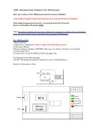
Leuze electronic<br />
<strong>Bus</strong>-<strong>Capable</strong> <strong>Optical</strong> <strong>Data</strong> <strong>Transmission</strong><br />
<strong>DDLS</strong> <strong>200</strong><br />
Technical Description
All rights reserved, especially the right of reproduction, distribution and translation. This document<br />
may not be duplicated or reproduced in any form (print, photocopy, microfilm or data recording) without<br />
the written permission of Leuze electronic GmbH + Co.<br />
It is subject to changes due to technical progress
Leuze electronic Table of contents<br />
1 General Information........................................................................................... 3<br />
1.1 Explanation of symbols ........................................................................................................ 3<br />
1.2 Declaration of conformity .....................................................................................................3<br />
1.3 Short description .................................................................................................................. 3<br />
1.4 Operating principle............................................................................................................... 4<br />
2 Safety Notices .................................................................................................... 5<br />
2.1 Safety standards .................................................................................................................. 5<br />
2.2 Intended use ........................................................................................................................ 5<br />
2.3 Working safely ..................................................................................................................... 5<br />
2.4 Organizational measures ..................................................................................................... 6<br />
3 Technical <strong>Data</strong> ................................................................................................... 7<br />
3.1 General technical data ......................................................................................................... 7<br />
3.2 Dimensioned drawing ..........................................................................................................8<br />
4 Mounting / Installation (all device variants) .................................................... 9<br />
4.1 Mounting and alignment.......................................................................................................9<br />
4.2 Arrangement of adjacent transmission systems ................................................................ 10<br />
4.3 Electrical connection .......................................................................................................... 11<br />
4.3.1 Supply voltage ............................................................................................................................. 12<br />
4.3.2 Switching input............................................................................................................................. 13<br />
4.3.3 Switching output .......................................................................................................................... 13<br />
5 PROFIBUS / RS 485 ......................................................................................... 14<br />
5.1 Electrical connection PROFIBUS....................................................................................... 14<br />
5.2 Device connection PROFIBUS .......................................................................................... 15<br />
5.3 LED indicators PROFIBUS ................................................................................................ 16<br />
6 INTERBUS 500 kBit/s / RS 422........................................................................ 17<br />
6.1 Electrical connection INTERBUS 500 kBit/s ...................................................................... 17<br />
6.2 Device connection INTERBUS 500 kBit/s / RS 422........................................................... 18<br />
6.3 LED indicators INTERBUS 500 kBit/s / RS 422................................................................. 19<br />
7 INTERBUS 2 MBit/s Fibre Optic Cable........................................................... 20<br />
7.1 Fibre optic cable connection INTERBUS 2 MBit/s ............................................................. 20<br />
7.2 Device connection INTERBUS 2 MBit/s fibre optic cable .................................................. 21<br />
7.3 LED indicators INTERBUS 2 MBit/s fibre optic cable ........................................................ 22<br />
8 <strong>Data</strong> Highway + (DH+) / Remote I/O (RIO)...................................................... 23<br />
8.1 Electrical connection DH+ / RIO ........................................................................................ 23<br />
8.2 Device configuration DH+ / RIO ......................................................................................... 24<br />
8.3 LED indicators DH+ / RIO .................................................................................................. 25<br />
Leuze electronic Technical description <strong>DDLS</strong> <strong>200</strong> 1
Table of contents Leuze electronic<br />
9 Commissioning / Operation (all device models)........................................... 26<br />
9.1 Indicator and operating elements....................................................................................... 26<br />
9.2 Operating modes ...............................................................................................................27<br />
9.3 Initial commissioning.......................................................................................................... 27<br />
9.3.1 Switch on device / function check ................................................................................................27<br />
9.3.2 Fine adjustment............................................................................................................................28<br />
9.4 Operation ........................................................................................................................... 29<br />
10 Maintenance ..................................................................................................... 30<br />
10.1 Cleaning............................................................................................................................. 30<br />
11 Diagnostics and Troubleshooting.................................................................. 31<br />
11.1 Status display on the device .............................................................................................. 31<br />
11.2 Troubleshooting ................................................................................................................. 32<br />
2 Technical description <strong>DDLS</strong> <strong>200</strong> Leuze electronic
Leuze electronic General Information<br />
1 General Information<br />
1.1 Explanation of symbols<br />
The symbols used in this operating manual are explained below.<br />
Attention!<br />
Pay attention to passages marked with this symbol. Failure to heed this information can lead<br />
to injuries to personnel or damage to the equipment.<br />
Attention Laser!<br />
This symbol warns of possible danger through hazardous laser radiation.<br />
Note!<br />
This symbol indicates text passages containing important information.<br />
1.2 Declaration of conformity<br />
The optical <strong>DDLS</strong> <strong>200</strong> data transmission system was designed and manufactured in accordance with<br />
applicable European normatives and guidelines.<br />
Note!<br />
The corresponding declaration of conformity can be requested from the manufacturer.<br />
The manufacturer of the product, Leuze electronic GmbH + Co. in D-73277 Owen/Teck, possesses a<br />
certified quality assurance system in accordance with ISO 9001.<br />
1.3 Short description<br />
Where data have to be transmitted to and from moving objects, optical data transmission systems provide<br />
an ideal solution.<br />
With the <strong>DDLS</strong> <strong>200</strong> Series, Leuze electronic offers optical, high-performance data transmission systems.<br />
The data transmission units are robust and are not subject to wear.<br />
A <strong>DDLS</strong> <strong>200</strong> data transmission system consists of a set of two transmission and reception units: e.g.<br />
<strong>DDLS</strong> <strong>200</strong>/<strong>200</strong>.1-10 and <strong>DDLS</strong> <strong>200</strong>/<strong>200</strong>.2-10.<br />
Leuze electronic Technical description <strong>DDLS</strong> <strong>200</strong> 3<br />
TNT 35/7-24V
General Information Leuze electronic<br />
Features of the <strong>DDLS</strong> <strong>200</strong><br />
The fact that bus systems are found in nearly all areas of industry places high demands on data transmission<br />
systems. The <strong>DDLS</strong> <strong>200</strong> fulfils these requirements, particularly with regard to:<br />
• <strong>Transmission</strong> safety<br />
Flexibility<br />
Handling<br />
The <strong>DDLS</strong> <strong>200</strong> data transmission system, which is available in several model variations, makes possible<br />
the contact-free transmission of the following bus protocols:<br />
PROFIBUS FMS, DP, MPI, FMS - DP mixed-operation, up to max. 1.5 MBit/s,<br />
INTERBUS 500 kBit/s, RS 422 general, copper cable<br />
INTERBUS 2 MBit/s / 500 kBit/s, fibre optic cable<br />
<strong>Data</strong> Highway + (DH+) from Rockwell Automation (Allen Bradley)<br />
Remote I/O (RIO) from Rockwell Automation (Allen Bradley)<br />
Other bus systems on request.<br />
1.4 Operating principle<br />
To prevent the devices from mutually interfering with one another during data transmission in duplex<br />
operation, they use two different frequency pairs. These are indicated by the type designation ….1<br />
and ….2 as well as the label frequency f 1 and frequency f 2 on the control panel.<br />
<strong>DDLS</strong> <strong>200</strong>/XXX.1-YY <strong>DDLS</strong> <strong>200</strong>/XXX.2-YY<br />
Figure 1.1: Operating principle<br />
f2<br />
<strong>Optical</strong> data transmission on<br />
two frequencies<br />
The receiving level is checked at both devices and can be read on a bar graph LED indicator. If the<br />
receiving level drops below a certain value, e.g. due to increased soiling of the optics, a warning output<br />
is activated.<br />
All work on the device (mounting, connecting, aligning, indicator/operating elements) is performed<br />
comfortably on the front side.<br />
4 Technical description <strong>DDLS</strong> <strong>200</strong> Leuze electronic<br />
f1
Leuze electronic Safety Notices<br />
2 Safety Notices<br />
2.1 Safety standards<br />
The optical <strong>DDLS</strong> <strong>200</strong> data transmission system was developed, manufactured and tested in accordance<br />
with applicable safety standards. It corresponds to the state of the art.<br />
2.2 Intended use<br />
The <strong>DDLS</strong> <strong>200</strong> optical data transmission system has been designed and developed for the optical<br />
transmission of data in the infrared range.<br />
Attention!<br />
The protection of personnel and the device cannot be guaranteed if the device is operated<br />
in a manner not corresponding to its intended use.<br />
Areas of application<br />
The <strong>DDLS</strong> <strong>200</strong> is suitable for the following areas of application:<br />
Automated high-bay warehouses<br />
Stationary data transmission between buildings<br />
Anywhere, where data transmission to and from stationary or moving objects (visual contact) over<br />
relatively long distances (up to <strong>200</strong> m) is required.<br />
Rotary transmission<br />
2.3 Working safely<br />
Attention Laser!<br />
The <strong>DDLS</strong> <strong>200</strong> data transmission system is an infrared laser device of Laser Class 1 in accordance<br />
with EN 60825. Do not look directly at the laser beam at close range!<br />
Laser Class 1 permits the use of optical instruments for the direct observation of the laser<br />
beam. The laser beam outlet is located on the front side in the upper third of the optics window.<br />
Observe the legal and local regulations applicable to the operation of laser units.<br />
Attention!<br />
Access and changes to the device, except where expressly described in this operating manual,<br />
are not authorised.<br />
Leuze electronic Technical description <strong>DDLS</strong> <strong>200</strong> 5<br />
TNT 35/7-24V
Safety Notices Leuze electronic<br />
2.4 Organisational measures<br />
Documentation<br />
All entries in this operating manual must be heeded, in particular those in the sections "Safety Notices"<br />
and "Commissioning". Keep this technical description in a safe place. It should be accessible at all<br />
times.<br />
Safety regulations<br />
Observe the locally applicable legal regulations and the rules of the employers' liability insurance association.<br />
Qualified personnel<br />
Mounting, commissioning and maintenance of the device may only be carried out by qualified personnel.<br />
Work on electrical installations may only be carried out by qualified electricians.<br />
Repair<br />
Repairs must only be carried out by the manufacturer or an authorised representative.<br />
6 Technical description <strong>DDLS</strong> <strong>200</strong> Leuze electronic
Leuze electronic Technical <strong>Data</strong><br />
3 Technical <strong>Data</strong><br />
3.1 General technical data<br />
Electrical data<br />
Supply voltage Vin 18 … 30 V DC<br />
Current consumption without optics approx. <strong>200</strong> mA with 24 V DC (no load at switching output)<br />
heating<br />
Current consumption w. optics heating approx. 800 mA with 24 V DC (no load at switching output)<br />
<strong>Optical</strong> data<br />
Sensing distance 0.2 … 120 m (<strong>DDLS</strong> <strong>200</strong>/120…)<br />
0.2 … <strong>200</strong> m (<strong>DDLS</strong> <strong>200</strong>/<strong>200</strong>…)<br />
<strong>Transmission</strong> diode infrared light, wavelength 880 nm<br />
Opening angle ± 0.5 ° to optical axis<br />
Ambient light > 10000 Lux acc. to EN 60947-5-2 (<strong>200</strong>0)<br />
Laser safety class 1 acc. to EN 60825-1 (<strong>200</strong>1)<br />
Input/output<br />
Input 0 … 2 V DC: transmitter/receiver deactivated<br />
18 … 30 V DC: transmitter/receiver activated<br />
Output 0 … 2 V DC: normal operation<br />
Vin - 2 V DC: limited performance reserve<br />
output current max. 100 mA, short-circuit proof,<br />
protected against surge voltage, transients and overheating<br />
Operating and display elements<br />
Membrane buttons change the operating mode<br />
Individual LEDs indicate voltage supply, operating mode, data traffic<br />
LED strip bar graph display of the receiving level<br />
Mechanical data<br />
Housing aluminium diecast; light inlet/outlet, glass<br />
Weight approx. 1<strong>200</strong> g<br />
Protection class IP 65 acc. to EN 60529<br />
Environmental conditions<br />
Operating temperature -5 °C … +50 °C without optics heating<br />
-30 °C … +50 °C with optics heating (non-condensing)<br />
Storage temperature -30°C … +70°C<br />
Air humidity max. 90% rel. humidity, non-condensing<br />
Vibrations acc. to EN 60068-2-6<br />
Noise acc. to EN 60068-2-64<br />
Shock acc. to EN 60068-2-27 and EN 60068-2-29<br />
EMC acc. to EN 61326 (1998) + A1 (1999)<br />
Leuze electronic Technical description <strong>DDLS</strong> <strong>200</strong> 7<br />
TNT 35/7-24V
Technical <strong>Data</strong> Leuze electronic<br />
3.2 Dimensioned drawing<br />
Figure 3.1: Dimensioned drawing <strong>DDLS</strong> <strong>200</strong> for copper cable<br />
Figure 3.2: Dimensioned drawing <strong>DDLS</strong> <strong>200</strong> for fibre optic cable<br />
Permissible cables:<br />
M16 x 1.5:<br />
round cable Ø 5 … 10 mm<br />
A control panel<br />
B transmission optics<br />
C reception optics<br />
D optical axis<br />
Permissible cables:<br />
M16 x 1.5:<br />
round cable Ø 5 … 10 mm<br />
M20 x 1.5:<br />
round cable Ø 7 … 12 mm<br />
A control panel<br />
B transmission optics<br />
C reception optics<br />
D optical axis<br />
8 Technical description <strong>DDLS</strong> <strong>200</strong> Leuze electronic
Leuze electronic Mounting / Installation (all device variants)<br />
4 Mounting / Installation (all device variants)<br />
4.1 Mounting and alignment<br />
An optical data transmission system, consisting of 2 <strong>DDLS</strong> <strong>200</strong> devices, involves mounting each of<br />
the devices on mutually opposing, plane-parallel, flat and usually vertical walls with unobstructed view<br />
of the opposing <strong>DDLS</strong> <strong>200</strong>.<br />
Make certain that, at the minimum operating distance Amin the optical axes of the devices are aligned<br />
with one another within ± Amin 0.01 to ensure that the transmission/reception beams of the two devices<br />
lie within the opening angle. This also applies for rotary transmission.<br />
Note<br />
The opening angle (angle of radiation) of the optics is ± 0.5 ° to the optical axis! The horizontal<br />
and vertical adjustment angles of the fine alignment with the adjustment screws is ±<br />
6 ° for each. The optical transmission path between the <strong>DDLS</strong> <strong>200</strong>s should not be interrupted.<br />
If interruptions cannot be avoided, be sure to read the notice in chapter 9.4.<br />
Therefore, pay close attention when selecting a suitable mounting location!<br />
Attention!<br />
When laying out a mobile arrangement for a <strong>DDLS</strong> <strong>200</strong>, pay particular attention that the<br />
alignment of the devices relative to one another remains unchanged over the transmission<br />
path.<br />
The transmission can be interrupted by e.g. jolts, vibrations or inclination of the mobile device<br />
due to irregularities in the floor or path.<br />
Ensure adequate track stability!<br />
Mount each device with 4 screws � 5 mm using 4 of the 5 fastening holes in the mounting plate of the<br />
device (see chapter 3.2 "Dimensioned drawing").<br />
<strong>DDLS</strong> <strong>200</strong>/XXX.1-YY <strong>DDLS</strong> <strong>200</strong>/XXX.2-YY<br />
( frequency f1 ) ( frequency f2 )<br />
Figure 4.1: Mounting the devices<br />
<strong>Optical</strong> axis<br />
Horizontal<br />
and vertical<br />
max. ± (Amin 0.01)<br />
A min<br />
Rotary transmission<br />
Note<br />
The fine alignment of the transmission system is performed during commissioning<br />
(see chapter 9.3.2 "Fine adjustment"). The position of the optical axis of the <strong>DDLS</strong> <strong>200</strong> can<br />
be found in chapter 3.2.<br />
Leuze electronic Technical description <strong>DDLS</strong> <strong>200</strong> 9<br />
TNT 35/7-24V
Mounting / Installation (all device variants) Leuze electronic<br />
4.2 Arrangement of adjacent transmission systems<br />
To prevent mutual interference of adjacent transmission systems, the following measures should be<br />
taken in addition to exact alignment:<br />
With a frequency-offset arrangement, the distance between two parallel transmission paths must<br />
not be less than 300 mm (<strong>DDLS</strong> <strong>200</strong>/120…) or 500 mm (<strong>DDLS</strong> <strong>200</strong>/<strong>200</strong>…).<br />
With arrangements using identical frequencies, the distance between two parallel transmission<br />
paths must be at least 500 mm + tan (0.5°) x sensing distance (<strong>DDLS</strong> <strong>200</strong>/<strong>200</strong>…), or<br />
300 mm + tan (0.5°) x sensing distance (<strong>DDLS</strong> <strong>200</strong>/120…).<br />
<strong>DDLS</strong> <strong>200</strong>/XXX.1-YY <strong>DDLS</strong> <strong>200</strong>/XXX.2-YY<br />
( frequency f1 ) ( frequency f2 )<br />
Frequency-offset arrangement!<br />
<strong>DDLS</strong> <strong>200</strong>/XXX.2-YY<br />
( frequency f2 ) ( frequency f1 )<br />
Identical frequency arrangement<br />
Min. 300 mm (<strong>DDLS</strong> <strong>200</strong>/120…)<br />
Min. 500 mm (<strong>DDLS</strong> <strong>200</strong>/<strong>200</strong>…)<br />
Min. tan (0.5 °) x sensing dis-<br />
<strong>DDLS</strong> <strong>200</strong>/XXX.1-YY <strong>DDLS</strong> <strong>200</strong>/XXX.2-YY<br />
( frequency f1 ) ( frequency f2 )<br />
Figure 4.2: Arrangement of adjacent transmission systems<br />
<strong>DDLS</strong> <strong>200</strong>/XXX.1-YY<br />
10 Technical description <strong>DDLS</strong> <strong>200</strong> Leuze electronic
Leuze electronic Mounting / Installation (all device variants)<br />
4.3 Electrical connection<br />
Attention!<br />
Connection of the device and maintenance work while under voltage must only be carried<br />
out by a qualified electrician.<br />
If faults cannot be corrected, the device should be removed from operation and protected<br />
against possible use.<br />
Before connecting the device, be sure that the supply voltage agrees with the value printed<br />
on the nameplate.<br />
The power supply unit used to power the <strong>DDLS</strong> <strong>200</strong> must have protected electrical separation<br />
by way of a safety transformer with double insulation according to EN 60742 (equivalent<br />
IEC 60742).<br />
Be sure that the earthing conductor is connected correctly. Error-free operation is guaranteed<br />
only when the device is properly earthed.<br />
Described in this section is the electrical connection of the supply voltage, the input and the output.<br />
These connections and their functions are identical for all device variants.<br />
The connection of the respective bus system is described in the following chapters.<br />
To establish the electrical connections, you must first remove the red housing top with the optics. To<br />
do this, loosen the three housing hex screws. The housing top is now only electrically connected to<br />
the base by means of a connector. Carefully pull the housing top straight forward without skewing.<br />
Carefully pull off the<br />
housing top<br />
Figure 4.3: Removing the housing top<br />
Loosen the 3<br />
housing<br />
screws<br />
Leuze electronic Technical description <strong>DDLS</strong> <strong>200</strong> 11<br />
TNT 35/7-24V
Mounting / Installation (all device variants) Leuze electronic<br />
The connection compartment in the housing base with the screwed cable glands is now freely accessible.<br />
Max. core<br />
cross section:<br />
1.5 mm 2<br />
PE<br />
Figure 4.4: Positions of the general, non-bus-specific terminals and switches<br />
4.3.1 Supply voltage<br />
OUT<br />
WARN PE GND Vin<br />
S1<br />
IN<br />
Off<br />
On<br />
IN PE GND Vin<br />
Terminal Function<br />
Vin Positive supply voltage<br />
+18 … +30 V DC<br />
GND Negative supply voltage 0VDC PE Earth lead<br />
OUT Switching output, activated if level<br />
WARN drops below the warning level<br />
IN Switching input for transmitter/receiver<br />
cut-off:<br />
0…2VDC: transmitter/receiver<br />
switched off, no transmission<br />
18 … 30 V DC: transmitter/receiver<br />
active, normal function<br />
Switch Function<br />
S1 On: the switching input is not analysed.<br />
The transmitter/receiver unit is always in<br />
operation.<br />
Off: the switching input is analysed.<br />
Depending on the input voltage, normal<br />
function or transmitter/receiver unit<br />
switched off.<br />
Connect the supply voltage, including the earth lead, to the spring terminals labelled Vin, GND and<br />
PE (see figure 4.4).<br />
Note<br />
The connection terminals Vin, GND and PE are provided double to simplify wiring through<br />
the supply voltage to other devices.<br />
The earth lead can alternatively be connected at the screw terminal in the housing base<br />
(max. core cross section 2.5 mm 2 )<br />
If you would like to wire through the supply voltage, you should replace the filler plugs on the<br />
right side of the housing base with an M16 x 1.5 screwed cable gland and guide the continuing<br />
supply voltage cable through this gland. The housing seal is, in this way, ensured (Protection<br />
Class IP 65).<br />
The housing top can be removed and replaced while under voltage.<br />
12 Technical description <strong>DDLS</strong> <strong>200</strong> Leuze electronic
Leuze electronic Mounting / Installation (all device variants)<br />
4.3.2 Switching input<br />
The <strong>DDLS</strong> <strong>200</strong> is equipped with a switching input IN, via which the transmitter/receiver unit can be<br />
switched off, i.e. no infrared light is transmitted and at the bus terminals the corresponding bus bias<br />
level is present / the bus driver is high resistance.<br />
Input voltage: 0 … 2 V DC: transmitter/receiver switched off, no transmission<br />
(relative to GND) 18 … 30 V DC: transmitter/receiver active, normal function<br />
For easier operation, the switching input can be activated/deactivated via switch S1:<br />
Position S1: On the switching input is not analysed. The transmitter/receiver<br />
unit is always in operation (internal preselection of the switching<br />
input with Vin).<br />
Off The switching input is analysed. Depending on the input voltage,<br />
normal function or transmitter/receiver unit switched off.<br />
Note!<br />
When transmitter/receiver unit is switched off, the system behaves in the same way as in<br />
the event of a light beam interruption (see chapter 9.4 "Operation").<br />
The switching input can be used, for example, during a corridor change to completely avoid<br />
interference effects from other sensors or the data transmission.<br />
4.3.3 Switching output<br />
The <strong>DDLS</strong> <strong>200</strong> is equipped with a switching output OUT WARN which is activated if the receiving level<br />
in the receiver drops.<br />
Output voltage: 0 … 2 V DC: operating range<br />
(relative to GND) Vin - 2 V DC: warning or shutoff range<br />
The switching output is protected against: short-circuit, surge current, surge voltage, overheating<br />
and transients.<br />
Note!<br />
The <strong>DDLS</strong> <strong>200</strong> is still completely functional when the level of the receiving signal drops to<br />
the warning signal level. No performance reserve remains.<br />
Leuze electronic Technical description <strong>DDLS</strong> <strong>200</strong> 13<br />
TNT 35/7-24V
PROFIBUS / RS 485 Leuze electronic<br />
5 PROFIBUS / RS 485<br />
The PROFIBUS model of the <strong>DDLS</strong> <strong>200</strong> has the following features:<br />
Electrically isolated interface<br />
The <strong>DDLS</strong> does not occupy a PROFIBUS address<br />
Integrated repeater function (signal processing), can be switched off<br />
Protocol-independent data transmission, i.e. transmission of the FMS, DP, MPI,<br />
FMS/DP mixed operation protocols<br />
Connectable bus terminator (termination)<br />
6 baud rates can be set<br />
5.1 Electrical connection PROFIBUS<br />
The electrical connection to the PROFIBUS is made at the terminals A, B, and COM. The terminals<br />
A’, B’ and COM are provided for wiring through the bus.<br />
SHIELD AREA<br />
COM –<br />
COM A<br />
+ COM –'<br />
B COM A' +'<br />
B'<br />
OUT<br />
WARN PE GND Vin<br />
S2<br />
Term.<br />
Off<br />
On<br />
On =<br />
RS 485<br />
1<br />
Off = 0<br />
Profibus<br />
S3<br />
S1<br />
IN<br />
Off<br />
On<br />
On<br />
Off<br />
BS BS<br />
IN PE GND Vin<br />
Figure 5.1: Connection circuit board of the PROFIBUS model<br />
A400A<br />
PROFIBUS - terminals and switches<br />
Terminal Function<br />
A , – (N) PROFIBUS or (–) RS 485<br />
B, + (P) PROFIBUS or (+) RS 485<br />
COM Potential equalisation<br />
A’, –’ (N) PROFIBUS or (–) RS 485 of the<br />
wired-through bus<br />
B’, +’ (P) PROFIBUS or (+) RS 485 of the<br />
wired through bus<br />
Switch Function<br />
S2 Termination On/Off<br />
S3-1 … S3-3 Setting the baud rate of the<br />
PROFIBUS segment<br />
S3-4 Changeover PROFIBUS (Off) /<br />
RS 485 (On)<br />
Attention!<br />
Please be sure to observe the installation requirements (bus cables, cable lengths, shielding,<br />
etc.) defined in the PROFIBUS standard EN 50170 (Vol. 2).<br />
14 Technical description <strong>DDLS</strong> <strong>200</strong> Leuze electronic
Leuze electronic PROFIBUS / RS 485<br />
5.2 Device configuration PROFIBUS<br />
Termination (bus connection, factory setting: 'Off' = no termination)<br />
The PROFIBUS can be terminated via the switch S2 in the <strong>DDLS</strong> <strong>200</strong>. If the termination is active<br />
(S2 = On), internal bus resistors are connected as per the PROFIBUS standard and the PROFIBUS<br />
is not wired through at terminals A’ and B’.<br />
Activate the termination when the PROFIBUS segment begins or ends at the <strong>DDLS</strong> <strong>200</strong>.<br />
Setting the transmission rate (baud rate, factory setting: '000' = 9.6 kBit/s)<br />
You must set the transmission rate of your PROFIBUS segment using the three DIP switches S3-1<br />
through S3-3. Possible transmission rates are:<br />
9.6 kBit/s 19.2 kBit/s<br />
93.75 kBit/s 187.5 kBit/s<br />
500 kBit/s 1500 kBit/s<br />
Set the transmission rate in accordance with the table printed on the connection circuit board (see figure<br />
5.1).<br />
Changeover PROFIBUS / RS 485 (factory setting: 'Off' = PROFIBUS)<br />
The <strong>DDLS</strong> <strong>200</strong> has, as a standard function, a repeater function (signal processing) and is, with regard<br />
to the PROFIBUS, to be viewed as a repeater.<br />
Note!<br />
Please observe the guidelines specified in EN 50170 (Vol. 2) regarding the use of repeaters.<br />
The delay time of a data transmission path is maximum 1.5 µs + 1 T Bit.<br />
It is also possible to transmit other RS 485 protocols. For PROFIBUS applications, S3-4<br />
should be set to 'Off' ('0'). DIP-switch S3-4 can be used to switch off the repeater function<br />
for non-PROFIBUS applications (S3-4 = 'On'). In this case, no signal regeneration takes<br />
place; the RS 485 protocol must, however, still provide certain features<br />
Please contact the manufacturer if you would like to use the <strong>DDLS</strong> <strong>200</strong> for other protocols.<br />
Leuze electronic Technical description <strong>DDLS</strong> <strong>200</strong> 15<br />
TNT 35/7-24V
PROFIBUS / RS 485 Leuze electronic<br />
5.3 LED Indicators PROFIBUS<br />
In addition to the indicator and operating elements present in all device models (bar graph, buttons,<br />
LEDs AUT, MAN, ADJ; see chapter 9.1 "Indicator and operating elements"), the PROFIBUS model<br />
also has the following indicators:<br />
PWR Tx Rx<br />
AUT<br />
MAN<br />
ADJ<br />
LED PWR: green = operating indicator<br />
green flashing= transmitter /receiver unit switched off<br />
via switching input IN or hardware error<br />
off = no operating voltage<br />
LED Tx: green = data are being transmitted to the bus<br />
green flashing= with baud rates set to very low values,<br />
the LEDs Tx and Rx flicker. At very<br />
high baud rates (> 50 kBit/s), flashing<br />
LEDs Tx and Rx indicate faulty bus<br />
communication.<br />
off = no data on the transmission line<br />
LED Rx: green = data are being received by the bus<br />
green flashing= with baud rates set to very low values,<br />
the LEDs Tx and Rx flicker. At very<br />
high baud rates (> 50 kBit/s), flashing<br />
LEDs Tx and Rx indicate faulty bus<br />
communication.<br />
off = no data on the reception line<br />
Figure 5.2: Indicator/operating elements for the PROFIBUS model<br />
16 Technical description <strong>DDLS</strong> <strong>200</strong> Leuze electronic
Leuze electronic INTERBUS 500 kBit/s / RS 422<br />
6 INTERBUS 500 kBit/s / RS 422<br />
The INTERBUS model of the <strong>DDLS</strong> <strong>200</strong> has the following features:<br />
Electrically isolated interface<br />
The <strong>DDLS</strong> <strong>200</strong> is not an INTERBUS subscriber<br />
Protocol-independent data transmission, transparent compared to other RS 422 protocols<br />
500 kBit/s fixed transmission rate with INTERBUS,<br />
with RS 422 generally lower transmission rates as well<br />
6.1 Electrical connection INTERBUS 500 kBit/s<br />
The electrical connection to the INTERBUS is made at terminals DO… / DI… and COM as shown in<br />
figure 6.1.<br />
SHIELD AREA AREA<br />
S4<br />
<strong>Bus</strong><br />
COM DI1 DI1 D01 D01 In<br />
COM D02 D02 DI2 DI2 Out<br />
COM Tx Tx– Tx+ Rx Rx– Rx+<br />
S1 IN<br />
Off<br />
On<br />
BS<br />
OUT<br />
WARN PE GND Vin<br />
IN PE GND Vin<br />
Figure 6.1: Connection circuit board of the INTERBUS model<br />
A402A<br />
INTERBUS - terminals and switches<br />
Terminal Function<br />
DO1 / DI2, Rx+ Reception line +<br />
DO1 / DI2, Rx– Reception line –<br />
DI1 / DO2, Tx+ <strong>Transmission</strong> line +<br />
DI1 / DO2, Tx– <strong>Transmission</strong> line –<br />
COM Potential equalisation<br />
Switch Function<br />
S4 Position In: incoming bus with<br />
shielding connection<br />
via RC circuit<br />
Position Out: outgoing bus with<br />
direct shielding connection<br />
Attention!<br />
Please be sure to observe the installation requirements (bus cables, cable lengths, shielding,<br />
etc.) defined in the INTERBUS standard EN 50254<br />
Leuze electronic Technical description <strong>DDLS</strong> <strong>200</strong> 17<br />
TNT 35/7-24V
INTERBUS 500 kBit/s / RS 422 Leuze electronic<br />
INTERBUS Master<br />
COM<br />
DI2<br />
DI2<br />
DO2<br />
DO2<br />
COM<br />
DI1<br />
DI1<br />
DO1<br />
DO1<br />
<strong>Bus</strong><br />
termi-<br />
COM<br />
DI2<br />
DI2<br />
DO2<br />
DO2<br />
DO3<br />
DO3<br />
DI3<br />
DI3<br />
COM<br />
DO1<br />
DO1<br />
DI1<br />
DI1<br />
COM<br />
Figure 6.2: Connection of the <strong>DDLS</strong> <strong>200</strong> to the INTERBUS (copper line)<br />
6.2 Device configuration INTERBUS 500 kBit/s / RS 422<br />
Device configuration INTERBUS<br />
Changeover incoming/outgoing bus and shielding connection (factory setting: 'Out')<br />
Switch S4 must be used to specify in the <strong>DDLS</strong> <strong>200</strong> whether the connected bus cable is for the incoming<br />
bus (In) or outgoing bus (Out):<br />
Switch S4 Setting In: incoming bus, the shielding connection (clamp) is connected via an<br />
RC circuit to PE.<br />
Setting Out: outgoing bus, the shielding connection (clamp) is connected directly<br />
to PE.<br />
Incoming bus<br />
set S4 to In<br />
PLC<br />
Switch S4<br />
Setting IN<br />
Shielding connection<br />
of incoming bus<br />
1 MΩ 15 nF<br />
Figure 6.3: Shielding connection for incoming/outgoing bus<br />
Switch S4<br />
Setting OUT<br />
Shielding connection<br />
of outgoing bus<br />
PE PE<br />
18 Technical description <strong>DDLS</strong> <strong>200</strong> Leuze electronic<br />
DO2<br />
DO2<br />
DI2<br />
DI2<br />
COM<br />
DO1<br />
DO1<br />
DI1<br />
DI1<br />
COM<br />
Outgoing bus<br />
set S4 to Out<br />
Subscriber
Leuze electronic INTERBUS 500 kBit/s / RS 422<br />
Device configuration RS 422<br />
General RS 422 protocols can be transmitted with the <strong>DDLS</strong> <strong>200</strong>. No baud rate setting is necessary<br />
(max. 500 kBit/s). The shielding connection can be set via switch S4 as with the Interbus.<br />
Note!<br />
The delay time of a light path is 1.5 µs.<br />
6.3 LED indicators INTERBUS 500 kBit/s / RS 422<br />
In addition to the indicator and operating elements present in all device models (bar graph, buttons,<br />
LEDs AUT, MAN, ADJ; see chapter 9.1 "Indicator and operating elements"), the INTERBUS model<br />
also has the following indicators:<br />
PWR Tx Rx<br />
AUT<br />
MAN<br />
ADJ<br />
LED PWR: green = operating indicator<br />
green flashing= transmitter /receiver unit switched off<br />
via switching input IN or hardware error<br />
off = no operating voltage<br />
LED Tx: green = data are being transmitted to the bus<br />
green flashing= with baud rates set to very low values,<br />
the LEDs Tx and Rx flicker. At very<br />
high baud rates (> 50 kBit/s), flashing<br />
LEDs Tx and Rx indicate faulty bus<br />
communication.<br />
off = no data on the transmission line<br />
LED Rx: green = data are being received by the bus<br />
green flashing= with baud rates set to very low values,<br />
the LEDs Tx and Rx flicker. At very<br />
high baud rates (> 50 kBit/s), flashing<br />
LEDs Tx and Rx indicate faulty bus<br />
communication.<br />
off = no data on the reception line<br />
Figure 6.4: Indicator/operating elements for the INTERBUS model<br />
Leuze electronic Technical description <strong>DDLS</strong> <strong>200</strong> 19<br />
TNT 35/7-24V
INTERBUS 2 MBit/s Fibre Optic Cable Leuze electronic<br />
7 INTERBUS 2 MBit/s Fibre Optic Cable<br />
The INTERBUS fibre optic cable model of the <strong>DDLS</strong> <strong>200</strong> has the following features:<br />
<strong>Transmission</strong> protected against interference through the use of fibre optic cables<br />
<strong>Bus</strong> connection by means of polymer-fibre cable with FSMA connector<br />
The <strong>DDLS</strong> <strong>200</strong> is an INTERBUS subscriber (Ident-Code: 0x0C = 12dec), but does not occupy data<br />
in the bus<br />
Adjustable transmission rate 500 kBit/s or 2 MBit/s<br />
7.1 Fibre optic cable connection INTERBUS 2 MBit/s<br />
The connection to the INTERBUS is by means of the FSMA connectors H1 and H2 as shown in<br />
figure 7.1.<br />
Recommended fibre optic cable:<br />
PSM-LWL-KDHEAVY… (Phoenix Contact)<br />
PSM-LWL-RUGGED… (Phoenix Contact)<br />
Out IN<br />
H2<br />
H1<br />
OUT<br />
WARN PE GND Vin<br />
IN<br />
S1 IN<br />
Off<br />
On<br />
Out In<br />
<strong>Bus</strong> <strong>Bus</strong> S3<br />
500K<br />
2M<br />
S2<br />
BS BS<br />
A402A<br />
PE GND Vin<br />
Figure 7.1: Connection circuit board of the INTERBUS model<br />
INTERBUS - terminals and switches<br />
Fibre optic<br />
cable socket Function<br />
H1 Receiver fibre optic cable<br />
H2 Transmitter fibre optic cable<br />
Switch Function<br />
S2 Setting 500k: INTERBUS fibre-opticcable<br />
transmission rate<br />
500 kBit/s<br />
Setting 2M: INTERBUS fibre-opticcable<br />
transmission rate<br />
2MBit/s<br />
S3 Setting In <strong>Bus</strong>: incoming bus fibre<br />
optic cable<br />
Setting Out <strong>Bus</strong>: outgoing bus fibre<br />
optic cable<br />
20 Technical description <strong>DDLS</strong> <strong>200</strong> Leuze electronic
Leuze electronic INTERBUS 2 MBit/s Fibre Optic Cable<br />
Attention!<br />
Please be sure to observe the installation requirements defined in the INTERBUS standard<br />
EN 50254 and follow the handling and installation specifications for fibre optic cables as<br />
specified by the manufacturer.<br />
For the fibre optic cable guides, use only the large screwed cable gland M20 x 1.5. Do<br />
not bend beyond the specified minimum bending radius given for the fibre-optic-cable<br />
type used!<br />
Coupling<br />
group<br />
Fibre-opticcable<br />
bus<br />
terminal<br />
Fibre<br />
H1<br />
H2<br />
Switch S3<br />
Setting In <strong>Bus</strong><br />
Switch S3<br />
Setting Out <strong>Bus</strong><br />
Incoming bus Outgoing bus<br />
Subscriber<br />
Figure 7.2: Connection of the <strong>DDLS</strong> <strong>200</strong> to the INTERBUS (fibre optic cable)<br />
7.2 Device configuration INTERBUS 2 MBit/s LWL<br />
Subscriber<br />
Fibre optic<br />
cable<br />
<strong>Transmission</strong> rate changeover (factory setting: '2M')<br />
In the <strong>DDLS</strong> <strong>200</strong>, switch S2 must be used to specify in the transmission rate of the fibre-optic-cable<br />
INTERBUS:<br />
Switch S2 Setting 500k: transmission rate 500 kBit/s.<br />
Setting 2M: transmission rate 2 MBit/s.<br />
Changeover incoming/outgoing bus (factory setting: 'Out <strong>Bus</strong>')<br />
Switch S3 must be used to specify in the <strong>DDLS</strong> <strong>200</strong> whether the connected fibre optic cable is for the<br />
incoming bus (In <strong>Bus</strong>) or outgoing bus (Out <strong>Bus</strong>):<br />
Switch S3 Setting In <strong>Bus</strong>: incoming bus fibre optic cable,<br />
outgoing bus optical data transmission.<br />
Setting Out <strong>Bus</strong>: incoming bus optical data transmission,<br />
outgoing bus fibre optic cable.<br />
Leuze electronic Technical description <strong>DDLS</strong> <strong>200</strong> 21<br />
H2<br />
H1<br />
TNT 35/7-24V
INTERBUS 2 MBit/s Fibre Optic Cable Leuze electronic<br />
Note!<br />
The delay time of a light path is 2.5 µs.<br />
7.3 LED indicators INTERBUS 2 MBit/s fibre optic cable<br />
In addition to the indicator and operating elements present in all device models (bar graph, buttons,<br />
LEDs AUT, MAN, ADJ; see chapter 9.1 "Indicator and operating elements"), the INTERBUS model<br />
also has the following indicators:<br />
UL RC BA<br />
RD FO1 FO2<br />
UL = logic voltage U L<br />
AUT<br />
MAN<br />
ADJ<br />
RC = Remote <strong>Bus</strong> Check<br />
BA = <strong>Bus</strong> Activity<br />
RD = Remote <strong>Bus</strong> Disable<br />
FO1 = Fibre Optics 1<br />
FO2 = Fibre Optics 2<br />
LED UL: green = operating indicator (Power on)<br />
green flashing = transmitter /receiver unit switched off via<br />
switching input IN or hardware error<br />
off = no operating voltage<br />
LED RC: green = INTERBUS connection OK<br />
off = INTERBUS in reset mode or connection<br />
not OK<br />
LED BA: green = display of bus activity<br />
off = no bus activity<br />
LED RD: yellow = continuing bus switched off<br />
off = continuing bus detected<br />
LED FO1: yellow = initialisation faulty or MAU warning<br />
(Master in RUN state)<br />
off = initialisation OK, no MAU warning<br />
(Master in READY state)<br />
LED FO2: yellow = initialisation faulty or MAU warning<br />
(Master in RUN state)<br />
off = initialisation OK, no MAU warning<br />
(Master in READY state)<br />
Figure 7.3: Indicator/operating elements for the INTERBUS model<br />
Note!<br />
The <strong>DDLS</strong> <strong>200</strong> is an INTERBUS subscriber (Ident-Code: 0x0C = 12 dec). A current CMD subscriber<br />
description can be downloaded from http://www.leuze.de.<br />
If the value falls below the warning level (bar graph), a peripheral error message is transmitted<br />
via the INTERBUS. When this error message is transmitted, the glass optics are usually<br />
soiled (see chapter 10.1 "Cleaning") or the light path has been interrupted.<br />
You can also use the diagnostic options available via the INTERBUS.<br />
22 Technical description <strong>DDLS</strong> <strong>200</strong> Leuze electronic
Leuze electronic <strong>Data</strong> Highway + (DH+) / Remote I/O (RIO)<br />
8 <strong>Data</strong> Highway + (DH+) / Remote I/O (RIO)<br />
The DH+/RIO model of the <strong>DDLS</strong> <strong>200</strong> has the following features:<br />
Electrically isolated interface<br />
Direct connection to the <strong>Data</strong> Highway + and Remote I/O bus from Rockwell Automation<br />
(Allen Bradley)<br />
Adjustable transmission rate 57.6 / 115.2 or 230.4 kBit/s<br />
8.1 Electrical connection DH+ / RIO<br />
The electrical connection to the DH+ / RIO bus is made in accordance with the table on the connection<br />
circuit board at the terminals 1, 2 and 3. These terminals are provided double for wiring through the<br />
bus.<br />
Cable to be used: Bluehouse Twinax (Belden 9463 or Allen Bradley 1770-CD)<br />
DH+ RIO<br />
A401A-BS<br />
1 CLEAR BLUE<br />
2 SHIELD SHIELD<br />
3 BLUE CLEAR<br />
1 2 3<br />
82 Ω<br />
1 2 3<br />
OUT<br />
WARN PE GND Vin<br />
S2<br />
kBit/s 1 2<br />
57.6 1 0<br />
S3<br />
1 S2 S3<br />
1<br />
115.2 0 1<br />
230.4 0 0 0<br />
Filter On=1<br />
Filter Off=0<br />
IN PE GND Vin<br />
IN<br />
Off<br />
On<br />
S1<br />
Figure 8.1: Connection circuit board of the DH+ / RIO model<br />
DH+/RIO - terminals and switches<br />
Terminal Assignment DH+ Assignment RIO<br />
1 CLEAR BLUE<br />
2 SHIELD SHIELD<br />
3 BLUE CLEAR<br />
Switch Function<br />
S2-1, S2-2 Setting the transmission rate (see table<br />
on the connection circuit board),<br />
default: 230.4 kBit/s<br />
S3-1 Filter for interference-peak rejection.<br />
Setting On (1): filter switched on<br />
(default)<br />
Setting Off (0): filter switched off<br />
S3-2 Not used<br />
Attention!<br />
The right DH+ / RIO connections 1 and 3 are equipped standard with an 82 � resistor for<br />
terminating the bus. Remove this terminating resistor when the bus cable in the <strong>DDLS</strong> <strong>200</strong><br />
is to be wired through to another bus subscriber, i.e. the <strong>DDLS</strong> <strong>200</strong> is not the last device on<br />
the bus cable. The use of the <strong>DDLS</strong> <strong>200</strong> is limited to bus systems with 82 � termination.<br />
Leuze electronic Technical description <strong>DDLS</strong> <strong>200</strong> 23<br />
TNT 35/7-24V
<strong>Data</strong> Highway + (DH+) / Remote I/O (RIO) Leuze electronic<br />
8.2 Device configuration DH+ / RIO<br />
Cascading of multiple <strong>DDLS</strong> <strong>200</strong> transmission paths (filter, factory setting: 'On' = on)<br />
If multiple <strong>DDLS</strong> <strong>200</strong> transmission paths are to be cascaded within a bus segment (see figure 8.2),<br />
the filter for interference-peak suppression (switch S3-1) must be adjusted appropriately for the selected<br />
transmission rate.<br />
PLC<br />
1 <strong>DDLS</strong> transmission path<br />
Path 1<br />
2 <strong>DDLS</strong> transmission paths<br />
Path 1<br />
3 <strong>DDLS</strong> transmission paths<br />
Path 1<br />
Path 2<br />
Path 2 Path 3<br />
Figure 8.2: Cascading multiple optical transmission paths with DH+ / RIO<br />
In accordance with the following table, set the filter for each <strong>DDLS</strong> transmission path at both devices<br />
for the given path using switch S3-1.<br />
Baud rate<br />
1path<br />
Setting of S3-1 for<br />
2paths 3paths<br />
57.6 kBit/s Path 1: On (1)<br />
Path 1: On (1)<br />
Path 2: Off (0)<br />
Path 1: On (1)<br />
Path 2: Off (0)<br />
Path 3: Off (0)<br />
115.2 kBit/s<br />
and<br />
230.4 kBit/s<br />
Path 1: On (1)<br />
Path 1: On (1)<br />
Path 2: On (1)<br />
Path 1: On (1)<br />
Path 2: On (1)<br />
Path 3: On (1)<br />
Table 8.1: Filter settings when cascading multiple <strong>DDLS</strong> transmission paths<br />
Note!<br />
The delay time of a light path is: S3-1 On (1) = 1.5µs+1.5T Bit<br />
S3-1 Off (0) = 1.5 µs<br />
24 Technical description <strong>DDLS</strong> <strong>200</strong> Leuze electronic
Leuze electronic <strong>Data</strong> Highway + (DH+) / Remote I/O (RIO)<br />
8.3 LED indicators DH+ / RIO<br />
In addition to the indicator and operating elements present in all device models (bar graph, buttons,<br />
LEDs AUT, MAN, ADJ; see chapter 9.1 "Indicator and operating elements"), the DH+/RIO model also<br />
has the following indicators:<br />
PWR Tx Rx<br />
AUT<br />
MAN<br />
ADJ<br />
LED PWR: green = operating indicator<br />
green flashing= transmitter/receiver unit switched off<br />
via switching input IN or hardware error<br />
off = no operating voltage<br />
LED Tx: green = data are being transmitted to the bus<br />
green flashing= with baud rates set to very low values,<br />
the LEDs Tx and Rx flicker. At very<br />
high baud rates (> 50 kBit/s), flashing<br />
LEDs Tx and Rx indicate faulty bus<br />
communication.<br />
off = no data on the transmission line<br />
LED Rx: green = data are being received by the bus<br />
green flashing= with baud rates set to very low values,<br />
the LEDs Tx and Rx flicker. At very<br />
high baud rates (> 50 kBit/s), flashing<br />
LEDs Tx and Rx indicate faulty bus<br />
communication.<br />
off = no data on the reception line<br />
Figure 8.3: Indicator/operating elements of the DH+/RIO model<br />
Note!<br />
You can also use the diagnostic options available via the bus system.<br />
Leuze electronic Technical description <strong>DDLS</strong> <strong>200</strong> 25<br />
TNT 35/7-24V
Commissioning / Operation (all device models) Leuze electronic<br />
9 Commissioning / Operation (all device models)<br />
9.1 Indicator and operating elements<br />
All <strong>DDLS</strong> <strong>200</strong> device models have the following indicator and operating elements:<br />
Bar graph with 10 LEDs<br />
Operating mode LEDs AUT, MAN, ADJ<br />
Operating mode buttons<br />
Bar graph Operating mode buttons<br />
AUT<br />
MAN<br />
ADJ<br />
LEDs dependent on device model<br />
Figure 9.1: Indicator and operating elements common to all <strong>DDLS</strong> <strong>200</strong> device models<br />
Bar graph<br />
The bar graph displays the quality of the received signal (receiving level) at its own (operating modes<br />
"Automatic" and "Manual") or opposing (operating mode "Adjust") <strong>DDLS</strong> <strong>200</strong> (figure 9.2).<br />
Operating range:<br />
Warning range:<br />
Cut-off range:<br />
Operating mode LEDs<br />
Good receiving level, optical data transmission active, performance<br />
reserve, output OUT WARN not active<br />
(0 … 2 V DC)<br />
Receiving level in the warning range, continued error-free<br />
data transmission, no performance reserve, output OUT<br />
WARN active (Vin - 2 V DC), peripheral error message with<br />
INTERBUS fibre optic cable model<br />
Receiving level minimal, optical data transmission separated,<br />
output OUT WARN active (Vin - 2 V DC)<br />
Figure 9.2: Meaning of the bar graph for displaying the receiving level<br />
Operating mode LEDs<br />
The three green LEDs AUT, MAN and ADJ indicate the current operating mode (see chapter 9.2 "Operating<br />
modes") of the <strong>DDLS</strong> <strong>200</strong>.<br />
AUT: operating mode "Automatic"<br />
MAN: operating mode "Manual"<br />
ADJ: operating mode "Adjust"<br />
Operating mode buttons<br />
With the operating mode button, you can switch between the three operating modes "Automatic",<br />
"Manual" and "Adjust" (see chapter 9.2 "Operating modes").<br />
26 Technical description <strong>DDLS</strong> <strong>200</strong> Leuze electronic
Leuze electronic Commissioning / Operation (all device models)<br />
9.2 Operating modes<br />
The following table provides an overview of the <strong>DDLS</strong> <strong>200</strong> operating modes.<br />
Operating<br />
mode<br />
Description<br />
<strong>Optical</strong> data<br />
transmission<br />
Bar graph assignment<br />
Automatic, Normal operation Active Its own receiving level, display of<br />
AUT LED illu-<br />
the alignment quality of the<br />
minates<br />
opposing device<br />
Manual, Adjustment operation,<br />
Active Its own receiving level, display of<br />
MAN LED cut-off threshold on higher level<br />
the alignment quality of the<br />
illuminates<br />
opposing device<br />
Adjust, ADJ Adjustment operation,<br />
Separated Receiving level of the opposing<br />
LED illumi- cut-off threshold on higher level<br />
device, display of the alignment<br />
nates<br />
quality of own device<br />
Changing the operating mode<br />
AUT –> MAN Press the operating mode button for more than 2 seconds.<br />
Only the device on which the button was pressed switches to the "Manual" operating<br />
mode (MAN LED illuminates).<br />
MAN –> ADJ Press the operating mode button on one of the two devices.<br />
Both devices switch to the "Adjust" operating mode (both ADJ LEDs illuminate) when<br />
both were previously in the "Manual" operating mode.<br />
ADJ –> MAN Press the operating mode button on one of the two devices.<br />
Both devices switch to the "Manual" operating mode (both MAN LEDs illuminate).<br />
MAN –> AUT Press the operating mode button for more than 2 seconds.<br />
Only the device on which the button was pressed switches to the "Automatic" operating<br />
mode (AUT LED illuminates).<br />
Note!<br />
To switch to the "Adjust" (ADJ) operating mode, both devices belonging to a transmission<br />
path must first be in the "Manual" (MAN) operating mode. It is not possible to switch directly<br />
from the "Automatic" to the "Adjust" operating mode or vice versa.<br />
9.3 Initial commissioning<br />
9.3.1 Switch on device / function check<br />
After applying the operating voltage, the <strong>DDLS</strong> <strong>200</strong> first performs a self-test. If the self-test is successfully<br />
completed, the PWR or UL LED illuminates continuously and the <strong>DDLS</strong> <strong>200</strong> switches to the "Automatic"<br />
operating mode. If the connection to the opposing device exists, data can be transmitted<br />
immediately.<br />
Leuze electronic Technical description <strong>DDLS</strong> <strong>200</strong> 27<br />
TNT 35/7-24V
Commissioning / Operation (all device models) Leuze electronic<br />
If the PWR or UL LED flashes after switching on, there are two possible causes: either a hardware<br />
error has occurred or the transmitter/receiver unit has switched off via the switching input IN (chapter<br />
4.3.2).<br />
If the PWR or UL LED remains dark after switching on, there is either no voltage supply present (check<br />
connections and voltage) or a hardware error has occurred.<br />
9.3.2 Fine adjustment<br />
If you have mounted and switched on the two <strong>DDLS</strong> <strong>200</strong>s of a given optical transmission path and<br />
they are both in the "Automatic" operating mode, you can perform the fine adjustment of the devices<br />
relative to one another with the aid of the three alignment screws.<br />
Note!<br />
Note that with "alignment", the transmitter with the beam which is to be positioned as exactly<br />
as possible on the opposing receiver is always meant.<br />
At the maximum sensing distance, the bar graph does not show end-scale deflection even<br />
with optimal alignment!<br />
The <strong>DDLS</strong> <strong>200</strong> supports fast and easy fine adjustment. The optimisation of the alignment between<br />
the two devices of one transmission path can be performed by just one person. Use the following<br />
descriptive steps as a set of numbered instructions:<br />
1. Both devices are located close to one another (> 1 m). Ideally, the bar graphs of both devices<br />
display maximum end-scale deflection.<br />
2. Switch both devices to "Manual" (MAN) by pressing the button for a relatively long time (> 2 s).<br />
<strong>Data</strong> transmission remains active, only the internal cut-off threshold is changed to the warning<br />
threshold (yellow LEDs).<br />
3. While in the "Manual" operating mode, move until data transmission of the <strong>DDLS</strong> <strong>200</strong> is interrupted.<br />
The devices are not yet optimally aligned with one another.<br />
4. Briefly press the button to switch both devices to the "Adjust" operating mode (ADJ). <strong>Data</strong><br />
transmission remains interrupted.<br />
5. The devices can now be individually aligned. The result of the alignment can be read directly in<br />
the bar graph.<br />
6. When both devices are aligned, briefly pressing the button on one of the devices is enough to<br />
switch both back to the "Manual" operating mode (MAN). <strong>Data</strong> transmission is again active; the<br />
vehicle can continue its path. If data transmission is interrupted again, repeat steps 3 through 6.<br />
7. If the data transmission and the alignment are OK through the end of the path of motion, switch<br />
both devices back to the "Automatic" (AUT) operating mode by pressing the button for a relatively<br />
long time (> 2 s). The optical data transceiver is now ready for operation.<br />
28 Technical description <strong>DDLS</strong> <strong>200</strong> Leuze electronic
Leuze electronic Commissioning / Operation (all device models)<br />
9.4 Operation<br />
In running operation ("Automatic" operating mode) the <strong>DDLS</strong> operates maintenance-free. Only the<br />
glass optics need to be cleaned occasionally in the event of soiling. This can be checked by analysing<br />
the switching output OUT WARN (with the INTERBUS fibre optic cable model, a peripheral error message<br />
is also available). If the output is set, soiling of the <strong>DDLS</strong> <strong>200</strong>'s glass optics is often the cause<br />
(see chapter 10.1 "Cleaning").<br />
It must still be ensured that the light beam is not interrupted at any time.<br />
Attention!<br />
If, during operation of the <strong>DDLS</strong> <strong>200</strong>, the light beam is interrupted or one of the two devices<br />
is switched voltage free, the effect of the interruption on the entire network is equivalent to<br />
the interruption of a data line!<br />
In the event of an interruption (light beam interruption or switched voltage-free), the<br />
<strong>DDLS</strong> <strong>200</strong> switches off the network to a non-interacting state. The system reactions in the<br />
event of an interruption are to be defined together with the supplier of the PLC.<br />
Leuze electronic Technical description <strong>DDLS</strong> <strong>200</strong> 29<br />
TNT 35/7-24V
Maintenance Leuze electronic<br />
10 Maintenance<br />
10.1 Cleaning<br />
The optical window of the <strong>DDLS</strong> <strong>200</strong> is to be cleaned monthly or as needed (warning output). To clean,<br />
use a soft cloth and a cleaning agent (standard glass cleaner).<br />
Attention!<br />
Do not use solvents and cleaning agents containing acetone. Use of improper cleaning<br />
agents can damage the optical window.<br />
30 Technical description <strong>DDLS</strong> <strong>200</strong> Leuze electronic
Leuze electronic Diagnostics and Troubleshooting<br />
11 Diagnostics and Troubleshooting<br />
11.1 Status display on the device<br />
The LEDs on the control panel of the <strong>DDLS</strong> <strong>200</strong> provide information about possible faults and errors.<br />
The descriptions of the states of the <strong>DDLS</strong> <strong>200</strong>'s LEDs are found for<br />
all models in chapter 9.1<br />
the model PROFIBUS / RS 485 in chapter 5.3<br />
the model INTERBUS 500 kBit/s / RS 422 in chapter 6.3<br />
the model INTERBUS 2 MBit/s fibre optic cable in chapter 7.3<br />
the model <strong>Data</strong> Highway + / Remote I/O in chapter 8.3<br />
Note!<br />
The INTERBUS 2 MBit/s fibre optic cable model of the <strong>DDLS</strong> <strong>200</strong> is an INTERBUS subscriber<br />
(Ident-Code: 0x0C = 12dec). You can also use the diagnostic options available via the<br />
INTERBUS.<br />
Leuze electronic Technical description <strong>DDLS</strong> <strong>200</strong> 31<br />
TNT 35/7-24V
Diagnostics and Troubleshooting Leuze electronic<br />
11.2 Troubleshooting<br />
Error Possible cause Remedy<br />
PWR or UL LED No supply voltage<br />
Check connections and supply volt-<br />
does not illumiage<br />
at the device; switch back on.<br />
nate<br />
Hardware defect<br />
In event of defect, replace device and<br />
send in for repair.<br />
PWR or UL LED Transmitter/receiver unit is switched Check input IN and setting of switch<br />
flashes<br />
off via input IN.<br />
S1.<br />
Hardware defect<br />
In event of defect, replace device and<br />
send in for repair.<br />
ADJ LED flashes Light beam interruption or no visual<br />
connection to opposing device<br />
(when opposing device is in the<br />
"Manual" operating mode).<br />
Misalignment of a <strong>DDLS</strong> <strong>200</strong> (when<br />
Check light path<br />
opposing device is in the "Manual"<br />
operating mode).<br />
Realign transmission path<br />
<strong>Bus</strong> operation not <strong>Transmission</strong> error<br />
See error "transmission error"<br />
possible<br />
Wiring error<br />
Check wiring<br />
Adjustment error (termination, baud<br />
rate, configuration)<br />
Check settings<br />
Incorrect bus cable<br />
Use specified bus cable<br />
Check for correct wiring and S1 set-<br />
Transmitter/receiver unit deactivated ting<br />
Set to "Adjust" operating mode, ADJ<br />
LED must not flash<br />
<strong>Transmission</strong> Receiving level too low due to<br />
error<br />
Misalignment<br />
Realign (check in "Adjust" operating<br />
mode)<br />
Clean daylight filter<br />
Observe operating limits<br />
Soiling<br />
Operation with excessively<br />
large operating ranges<br />
Influenced by parallel data path<br />
Influenced by cascading data paths<br />
Shielding not connected<br />
Incorrect bus termination<br />
Earth lead not connected<br />
Intense, direct ambient light<br />
Operate data transmission units with<br />
alternating frequency assignments<br />
Operate data transmission units with<br />
alternating frequency assignments<br />
Connect shielding correctly<br />
Disconnect/connect terminating<br />
resistors<br />
Connect earth lead<br />
Remove ambient light source<br />
32 Technical description <strong>DDLS</strong> <strong>200</strong> Leuze electronic
Sales and Service<br />
A<br />
Ing. Franz Schmachtl KG<br />
Tel. Int. + 43 (0) 732/7646-0<br />
Fax Int. + 43 (0) 732/785036<br />
E-mail: office.linz@schmachtl.at<br />
ARG<br />
Nortécnica S. R. L.<br />
Tel. Int. + 54 (0) 11/4757-3129<br />
Fax Int. + 54 (0) 11/4757-1088<br />
E-mail: info@nortecnica.com.ar<br />
AUS + NZ<br />
Balluff-Leuze Pty. Ltd.<br />
Tel. Int. + 61 (0) 3/97642366<br />
Fax Int. + 61 (0) 3/97533262<br />
E-mail: balluff_leuze@matcol.com.au<br />
B<br />
Leuze electronic nv/sa<br />
Tel. Int. + 32 (0) 2/2531600<br />
Fax Int. + 32 (0) 2/2531536<br />
E-mail: leuze.info@leuze.be<br />
BR<br />
Leuze electronic Ltda.<br />
Tel. Int. + 55 (0) 11/ 4195-6134<br />
Fax Int. + 55 (0) 11/ 4195-6177<br />
E-mail: leuzeelectronic@originet.com.br<br />
CH<br />
Leuze electronic AG<br />
Tel. Int. + 41 (0) 1/8340204<br />
Fax Int. + 41 (0) 1/8332626<br />
E-mail: leuze@leuze.ch<br />
CZ<br />
Schmachtl CZ Spol. SR. O.<br />
Tel. Int. + 420 (0) 2/44001500<br />
Fax Int. + 420 (0) 2/44910700<br />
E-mail: office@schmachtl.cz<br />
http://www.schmachtl.cz<br />
CO<br />
Componentes Electronicas Ltda.<br />
Tel. Int. + 57 (0) 4/3511049<br />
Fax Int. + 57 (0) 4/3511019<br />
E-mail: rigogigu@co13.telecom.com.co<br />
DK<br />
Desim Elektronik APS<br />
Tel. Int. + 45/98510066<br />
Fax Int. + 45/98512220<br />
E-mail: desim@desim.dk<br />
D<br />
Leuze electronic GmbH + Co.<br />
Geschäftsstelle Dresden<br />
Telefon (0351) 2841105<br />
Telefax (0351) 2841103<br />
E-mail: vgd@leuze.de<br />
Lindner electronic GmbH<br />
Vertrieb Nord, Hannover<br />
Telefon (0511) 966057-0<br />
Telefax (0511) 966057-57<br />
E-mail: lindner@leuze.de<br />
W+M plantechnik<br />
Dipl.-Ing. Wörtler GmbH + Co.<br />
Vertrieb West, Wuppertal<br />
Telefon (0202) 37112-0<br />
Telefax (0202) 318495<br />
E-mail: wmplan@rga-net.de<br />
Leuze electronic GmbH + Co.<br />
Geschäftsstelle Frankfurt<br />
Telefon (06181) 9177-0<br />
Telefax (06181) 917715<br />
E-mail: vgf@leuze.de<br />
Leuze electronic GmbH + Co.<br />
Geschäftsstelle Owen/Bad.-Württ.<br />
Telefon (07021) 9850-910<br />
Telefax (07021) 9850-911<br />
E-mail: vgo@leuze.de<br />
Leuze electronic GmbH + Co.<br />
Geschäftsstelle München<br />
Telefon (089) 14365-<strong>200</strong><br />
Telefax (089) 14365-220<br />
E-mail: vgm@leuze.de<br />
E<br />
Leuze electronic S.A.<br />
Tel. Int. + 34 93/4097900<br />
Fax Int. + 34 93/4903515<br />
E-mail: leuze@chi.es<br />
F<br />
Leuze electronic sarl.<br />
Tel. Int. + 33 (0) 1/60051220<br />
Fax Int. + 33 (0) 1/60050365<br />
E-mail: infos@leuze-electronic.fr<br />
http://www.leuze-electronic.fr<br />
FIN<br />
SKS-tekniikka Oy<br />
Tel. Int. + 358 (0) 9/852661<br />
Fax Int. + 358 (0) 9/8526820<br />
E-mail: sks-tekniikka@sks.fi<br />
http://www.sks.fi<br />
GB<br />
Leuze Mayser electronic Ltd.<br />
Tel. Int. + 44 (0) 1480/408500<br />
Fax Int. + 44 (0) 1480/403808<br />
E-mail: mail@leuzemayser.co.uk<br />
http://www.leuzemayser.co.uk<br />
GR<br />
UTECO A.B.E.E.<br />
Tel. Int. + 30 (0) 1/4 210050<br />
Fax Int. + 30 (0) 1/4 212033<br />
E-mail: uteco@uteco.gr<br />
GUS + EST +<br />
All Impex GmbH<br />
LV + LT<br />
Telefon (0351) 8900946<br />
Telefax (0351) 8900947<br />
H<br />
Kvalix Automatika Kft.<br />
Tel. Int. + 36 (0) 1/3990615<br />
Fax Int. + 36 (0) 1/3698488<br />
E-mail: info@kvalix.hu<br />
http://www.kvalix.hu<br />
HK<br />
Sensortech Company<br />
Tel. Int. + 852/26510188<br />
Fax Int. + 852/26510388<br />
E-mail: sensortech@attglobal.net<br />
I<br />
IVO Leuze Vogtle Malanca s.r.l.<br />
Tel. Int. + 39 02/2840493<br />
Fax Int. + 39 02/26110640<br />
E-mail: ivoleuze@tin.it<br />
IL<br />
Galoz electronics Ltd.<br />
Tel. Int. + 972 (0) 3/9023456<br />
Fax Int. + 972 (0) 3/9021990<br />
IND<br />
Global Tech Corp.<br />
Tel. Int. + 91 (0) 20/4470085<br />
Fax Int. + 91 (0) 20/4 470086<br />
E-mail: globtech@giaspn01.vsnl.net.in<br />
J<br />
SSR Engineering Co., Ltd.<br />
Tel. Int. + 81 (0) 45/ 730-5580<br />
Fax Int. + 81 (0) 45/ 730-5587<br />
E-mail: info@ssr-eng.co.jp<br />
KOR<br />
Useong Electrade Co.<br />
Tel. Int. + 82 (0) 31/4561415/6<br />
Fax Int. + 82 (0) 31/4561442<br />
E-mail: haegon97@unitel.co.kr<br />
MAL<br />
Ingermark (M) SDN.BHD<br />
Tel. Int. + 60 (0) 3/60342788<br />
Fax Int. + 60 (0) 3/60342188<br />
E-mail: ingmal@tm.net.my<br />
MEX<br />
Leuze Lumiflex México, S.A. de C.V.<br />
Tel. Int. + 52 (0) 8352/4060<br />
Fax Int. + 52 (0) 8352/4034<br />
E-mail: leuzemexico@axtel.net<br />
http://www.leuze.de<br />
N<br />
Elteco A/S<br />
Tel. Int. + 47 (0) 35/573800<br />
Fax Int. + 47 (0) 35/573849<br />
NL<br />
Leuze electronic B.V.<br />
Tel. Int. + 31 (0) 30/6066300<br />
Fax Int. + 31 (0) 30/6060970<br />
E-mail: info@leuze.nl<br />
http://www.leuze.nl<br />
P<br />
LA2P, Lda.<br />
Tel. Int. + 351 (0) 21/4447070<br />
Fax Int. + 351 (0) 21/4447075<br />
E-mail: la2p@ip.pt<br />
http://www.la2p.pt<br />
PL<br />
Balluff Sp. z. o. o.<br />
Tel. Int. + 48 (0) 22/6519679<br />
Fax Int. + 48 (0) 22/8429728<br />
E-mail: balluff@balluff.pl<br />
RCH<br />
Imp. Tec. Vignola S.A.I.C.<br />
Tel. Int. + 56 (0) 32/256521<br />
Fax Int. + 56 (0) 32/258571<br />
E-mail: vignoval@entelchile.net<br />
ROC<br />
Great Cofue Technology Co., Ltd.<br />
Tel. Int. + 886 (0) 2/29838077<br />
Fax Int. + 886 (0) 2/29853373<br />
E-mail: gcofue@mail.eranet.net<br />
Leuze electronic<br />
Leuze electronic GmbH + Co.<br />
Postfach 11 11, D-73277 Owen/Teck<br />
Tel. (07021) 5730, Fax (07021) 573199<br />
E-mail: info@leuze.de<br />
http://www.leuze.de<br />
RP<br />
JMTI Industrial Corporation<br />
Tel. Int. + 63 (0) 2/8446326<br />
Fax Int. + 63 (0) 2/8932202<br />
RSA<br />
Countapulse Controls (PTY.) Ltd.<br />
Tel. Int. + 27 (0) 11/6157556-8<br />
Fax Int. + 27 (0) 11/6157513<br />
S<br />
Leuze electronic AB<br />
Tel. + 46 (0) 8/7315190<br />
Fax + 46 (0) 8/7315105<br />
E-mail: info@leuze.se<br />
SGP + RI<br />
Balluff Asia Pte Ltd<br />
Tel. Int. + 65/2524384<br />
Fax Int. + 65/2529060<br />
E-mail: balluff@balluff.com.sg<br />
SK<br />
Schmachtl SK s.r.o.<br />
Tel. Int. + 421 (0) 7/54777484<br />
Fax Int. + 421 (0) 7/54777491<br />
E-mail: office@schmachtl.sk<br />
SLO<br />
Tipteh d.o.o.<br />
Tel. Int. + 386 (0) 1/ <strong>200</strong>5150<br />
Fax Int. + 386 (0) 1/ <strong>200</strong>5151<br />
TH<br />
Industrial Electrical Co. Ltd.<br />
Tel. Int. + 66 (0) 2/6 42-6700<br />
Fax Int. + 66 (0) 2/6 42-4249<br />
TR<br />
MEGA Teknik elek. San. ve Tic. Ltd.<br />
Tel. Int. + 90 (0) 212/3<strong>200</strong>411<br />
Fax Int. + 90 (0) 212/3<strong>200</strong>416<br />
E-mail: mega@netone.com.tr<br />
USA + CDN<br />
Leuze Lumiflex Inc.<br />
Tel. Int. + 1 (0) 973/5860100<br />
Fax Int. + 1 (0) 973/586 1590<br />
E-mail: info@leuze-lumiflex.com<br />
http://www.leuze-lumiflex.com