Bus-Capable Optical Data Transmission DDLS 200 - VDT Industrie
Bus-Capable Optical Data Transmission DDLS 200 - VDT Industrie
Bus-Capable Optical Data Transmission DDLS 200 - VDT Industrie

You also want an ePaper? Increase the reach of your titles
YUMPU automatically turns print PDFs into web optimized ePapers that Google loves.
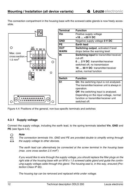
Mounting / Installation (all device variants) Leuze electronic<br />
The connection compartment in the housing base with the screwed cable glands is now freely accessible.<br />
Max. core<br />
cross section:<br />
1.5 mm 2<br />
PE<br />
Figure 4.4: Positions of the general, non-bus-specific terminals and switches<br />
4.3.1 Supply voltage<br />
OUT<br />
WARN PE GND Vin<br />
S1<br />
IN<br />
Off<br />
On<br />
IN PE GND Vin<br />
Terminal Function<br />
Vin Positive supply voltage<br />
+18 … +30 V DC<br />
GND Negative supply voltage 0VDC PE Earth lead<br />
OUT Switching output, activated if level<br />
WARN drops below the warning level<br />
IN Switching input for transmitter/receiver<br />
cut-off:<br />
0…2VDC: transmitter/receiver<br />
switched off, no transmission<br />
18 … 30 V DC: transmitter/receiver<br />
active, normal function<br />
Switch Function<br />
S1 On: the switching input is not analysed.<br />
The transmitter/receiver unit is always in<br />
operation.<br />
Off: the switching input is analysed.<br />
Depending on the input voltage, normal<br />
function or transmitter/receiver unit<br />
switched off.<br />
Connect the supply voltage, including the earth lead, to the spring terminals labelled Vin, GND and<br />
PE (see figure 4.4).<br />
Note<br />
The connection terminals Vin, GND and PE are provided double to simplify wiring through<br />
the supply voltage to other devices.<br />
The earth lead can alternatively be connected at the screw terminal in the housing base<br />
(max. core cross section 2.5 mm 2 )<br />
If you would like to wire through the supply voltage, you should replace the filler plugs on the<br />
right side of the housing base with an M16 x 1.5 screwed cable gland and guide the continuing<br />
supply voltage cable through this gland. The housing seal is, in this way, ensured (Protection<br />
Class IP 65).<br />
The housing top can be removed and replaced while under voltage.<br />
12 Technical description <strong>DDLS</strong> <strong>200</strong> Leuze electronic