Bus-Capable Optical Data Transmission DDLS 200 - VDT Industrie
Bus-Capable Optical Data Transmission DDLS 200 - VDT Industrie
Bus-Capable Optical Data Transmission DDLS 200 - VDT Industrie

You also want an ePaper? Increase the reach of your titles
YUMPU automatically turns print PDFs into web optimized ePapers that Google loves.
Leuze electronic Mounting / Installation (all device variants)<br />
4 Mounting / Installation (all device variants)<br />
4.1 Mounting and alignment<br />
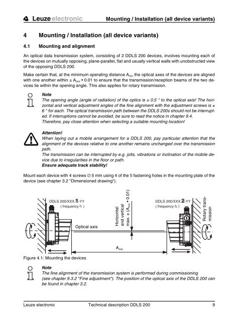
An optical data transmission system, consisting of 2 <strong>DDLS</strong> <strong>200</strong> devices, involves mounting each of<br />
the devices on mutually opposing, plane-parallel, flat and usually vertical walls with unobstructed view<br />
of the opposing <strong>DDLS</strong> <strong>200</strong>.<br />
Make certain that, at the minimum operating distance Amin the optical axes of the devices are aligned<br />
with one another within ± Amin 0.01 to ensure that the transmission/reception beams of the two devices<br />
lie within the opening angle. This also applies for rotary transmission.<br />
Note<br />
The opening angle (angle of radiation) of the optics is ± 0.5 ° to the optical axis! The horizontal<br />
and vertical adjustment angles of the fine alignment with the adjustment screws is ±<br />
6 ° for each. The optical transmission path between the <strong>DDLS</strong> <strong>200</strong>s should not be interrupted.<br />
If interruptions cannot be avoided, be sure to read the notice in chapter 9.4.<br />
Therefore, pay close attention when selecting a suitable mounting location!<br />
Attention!<br />
When laying out a mobile arrangement for a <strong>DDLS</strong> <strong>200</strong>, pay particular attention that the<br />
alignment of the devices relative to one another remains unchanged over the transmission<br />
path.<br />
The transmission can be interrupted by e.g. jolts, vibrations or inclination of the mobile device<br />
due to irregularities in the floor or path.<br />
Ensure adequate track stability!<br />
Mount each device with 4 screws � 5 mm using 4 of the 5 fastening holes in the mounting plate of the<br />
device (see chapter 3.2 "Dimensioned drawing").<br />
<strong>DDLS</strong> <strong>200</strong>/XXX.1-YY <strong>DDLS</strong> <strong>200</strong>/XXX.2-YY<br />
( frequency f1 ) ( frequency f2 )<br />
Figure 4.1: Mounting the devices<br />
<strong>Optical</strong> axis<br />
Horizontal<br />
and vertical<br />
max. ± (Amin 0.01)<br />
A min<br />
Rotary transmission<br />
Note<br />
The fine alignment of the transmission system is performed during commissioning<br />
(see chapter 9.3.2 "Fine adjustment"). The position of the optical axis of the <strong>DDLS</strong> <strong>200</strong> can<br />
be found in chapter 3.2.<br />
Leuze electronic Technical description <strong>DDLS</strong> <strong>200</strong> 9<br />
TNT 35/7-24V