Bus-Capable Optical Data Transmission DDLS 200 - VDT Industrie
Bus-Capable Optical Data Transmission DDLS 200 - VDT Industrie
Bus-Capable Optical Data Transmission DDLS 200 - VDT Industrie
You also want an ePaper? Increase the reach of your titles
YUMPU automatically turns print PDFs into web optimized ePapers that Google loves.
Commissioning / Operation (all device models) Leuze electronic<br />
If the PWR or UL LED flashes after switching on, there are two possible causes: either a hardware<br />
error has occurred or the transmitter/receiver unit has switched off via the switching input IN (chapter<br />
4.3.2).<br />
If the PWR or UL LED remains dark after switching on, there is either no voltage supply present (check<br />
connections and voltage) or a hardware error has occurred.<br />
9.3.2 Fine adjustment<br />
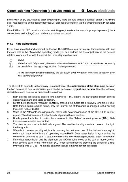
If you have mounted and switched on the two <strong>DDLS</strong> <strong>200</strong>s of a given optical transmission path and<br />
they are both in the "Automatic" operating mode, you can perform the fine adjustment of the devices<br />
relative to one another with the aid of the three alignment screws.<br />
Note!<br />
Note that with "alignment", the transmitter with the beam which is to be positioned as exactly<br />
as possible on the opposing receiver is always meant.<br />
At the maximum sensing distance, the bar graph does not show end-scale deflection even<br />
with optimal alignment!<br />
The <strong>DDLS</strong> <strong>200</strong> supports fast and easy fine adjustment. The optimisation of the alignment between<br />
the two devices of one transmission path can be performed by just one person. Use the following<br />
descriptive steps as a set of numbered instructions:<br />
1. Both devices are located close to one another (> 1 m). Ideally, the bar graphs of both devices<br />
display maximum end-scale deflection.<br />
2. Switch both devices to "Manual" (MAN) by pressing the button for a relatively long time (> 2 s).<br />
<strong>Data</strong> transmission remains active, only the internal cut-off threshold is changed to the warning<br />
threshold (yellow LEDs).<br />
3. While in the "Manual" operating mode, move until data transmission of the <strong>DDLS</strong> <strong>200</strong> is interrupted.<br />
The devices are not yet optimally aligned with one another.<br />
4. Briefly press the button to switch both devices to the "Adjust" operating mode (ADJ). <strong>Data</strong><br />
transmission remains interrupted.<br />
5. The devices can now be individually aligned. The result of the alignment can be read directly in<br />
the bar graph.<br />
6. When both devices are aligned, briefly pressing the button on one of the devices is enough to<br />
switch both back to the "Manual" operating mode (MAN). <strong>Data</strong> transmission is again active; the<br />
vehicle can continue its path. If data transmission is interrupted again, repeat steps 3 through 6.<br />
7. If the data transmission and the alignment are OK through the end of the path of motion, switch<br />
both devices back to the "Automatic" (AUT) operating mode by pressing the button for a relatively<br />
long time (> 2 s). The optical data transceiver is now ready for operation.<br />
28 Technical description <strong>DDLS</strong> <strong>200</strong> Leuze electronic


