Bus-Capable Optical Data Transmission DDLS 200 - VDT Industrie
Bus-Capable Optical Data Transmission DDLS 200 - VDT Industrie
Bus-Capable Optical Data Transmission DDLS 200 - VDT Industrie

Create successful ePaper yourself
Turn your PDF publications into a flip-book with our unique Google optimized e-Paper software.
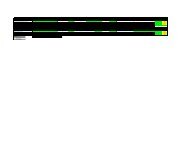
INTERBUS 500 kBit/s / RS 422 Leuze electronic<br />
INTERBUS Master<br />
COM<br />
DI2<br />
DI2<br />
DO2<br />
DO2<br />
COM<br />
DI1<br />
DI1<br />
DO1<br />
DO1<br />
<strong>Bus</strong><br />
termi-<br />
COM<br />
DI2<br />
DI2<br />
DO2<br />
DO2<br />
DO3<br />
DO3<br />
DI3<br />
DI3<br />
COM<br />
DO1<br />
DO1<br />
DI1<br />
DI1<br />
COM<br />
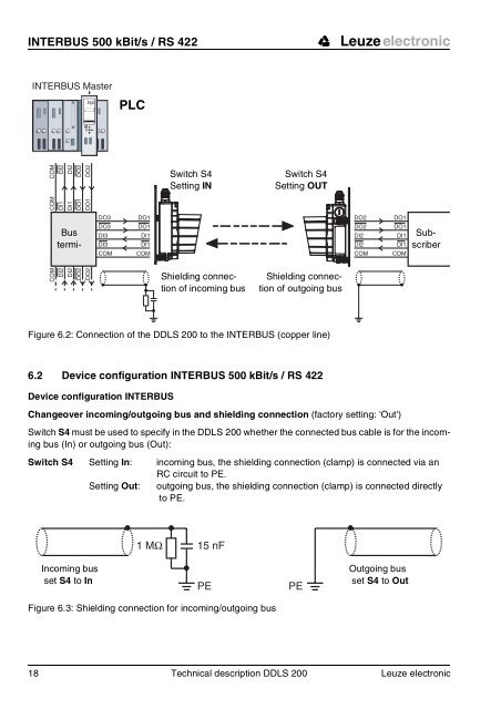
Figure 6.2: Connection of the <strong>DDLS</strong> <strong>200</strong> to the INTERBUS (copper line)<br />
6.2 Device configuration INTERBUS 500 kBit/s / RS 422<br />
Device configuration INTERBUS<br />
Changeover incoming/outgoing bus and shielding connection (factory setting: 'Out')<br />
Switch S4 must be used to specify in the <strong>DDLS</strong> <strong>200</strong> whether the connected bus cable is for the incoming<br />
bus (In) or outgoing bus (Out):<br />
Switch S4 Setting In: incoming bus, the shielding connection (clamp) is connected via an<br />
RC circuit to PE.<br />
Setting Out: outgoing bus, the shielding connection (clamp) is connected directly<br />
to PE.<br />
Incoming bus<br />
set S4 to In<br />
PLC<br />
Switch S4<br />
Setting IN<br />
Shielding connection<br />
of incoming bus<br />
1 MΩ 15 nF<br />
Figure 6.3: Shielding connection for incoming/outgoing bus<br />
Switch S4<br />
Setting OUT<br />
Shielding connection<br />
of outgoing bus<br />
PE PE<br />
18 Technical description <strong>DDLS</strong> <strong>200</strong> Leuze electronic<br />
DO2<br />
DO2<br />
DI2<br />
DI2<br />
COM<br />
DO1<br />
DO1<br />
DI1<br />
DI1<br />
COM<br />
Outgoing bus<br />
set S4 to Out<br />
Subscriber