KMD-201AA KMD-201AWA - Hoshizaki
KMD-201AA KMD-201AWA - Hoshizaki
KMD-201AA KMD-201AWA - Hoshizaki
- No tags were found...

You also want an ePaper? Increase the reach of your titles
YUMPU automatically turns print PDFs into web optimized ePapers that Google loves.
NO. F037-775ISSUED: JUN. 15, 2009REVISED:HOSHIZAKIMODULAR CRESCENT CUBERMODEL<strong>KMD</strong>-<strong>201AA</strong><strong>KMD</strong>-<strong>201AWA</strong>SERVICE MANUAL
CONTENTSPAGEI. SPECIFICATIONS --------------------------------------------------------------------------------------- 11. SPECIFICATIONS ---------------------------------------------------------------------------------- 1[a] <strong>KMD</strong>-<strong>201AA</strong> (air-cooled) ----------------------------------------------------------------------- 1[b] <strong>KMD</strong>-<strong>201AWA</strong> (water-cooled) ----------------------------------------------------------------- 2II. GENERAL INFORMATION --------------------------------------------------------------------------- 31. CONSTRUCTION ------------------------------------------------------------------------------------ 3[a] <strong>KMD</strong>-<strong>201AA</strong> ----------------------------------------------------------------------------------------3[b] <strong>KMD</strong>-<strong>201AWA</strong> -------------------------------------------------------------------------------------42. SEQUENCE OF OPERATION ------------------------------------------------------------------- 5[a] ONE MINUTE FILL CYCLE -------------------------------------------------------------------- 5[b] INITIAL HARVEST CYCLE -------------------------------------------------------------------- 5[c] FREEZE CYCLE ---------------------------------------------------------------------------------- 5[d] DRAIN CYCLE ------------------------------------------------------------------------------------ 5[e] NORMAL HARVEST CYCLE ------------------------------------------------------------------ 63. CONTROL BOARD ---------------------------------------------------------------------------------- 8[a] CONTROL BOARD LAYOUT ----------------------------------------------------------------- 9[b] FEATURES ---------------------------------------------------------------------------------------- 10[c] CONTROLS AND ADJUSTMENTS ---------------------------------------------------------- 12[d] CONTROL BOARD CHECK PROCEDURE ----------------------------------------------- 15[e] CONTROL BOARD REPLACEMENT ------------------------------------------------------- 154. HARVEST CONTROL – THERMISTOR -------------------------------------------------------- 155. FLOAT SWITCH -------------------------------------------------------------------------------------- 16[a] EXPLANATION OF OPERATION ------------------------------------------------------------ 16[b] CLEANING ----------------------------------------------------------------------------------------- 16[c] FLOAT SWITCH CHECK PROCEDURE --------------------------------------------------- 166. BIN CONTROL ---------------------------------------------------------------------------------------- 17[a] EXPLANATION OF OPERATION ------------------------------------------------------------ 17[b] BIN CONTROL CHECK PROCEDURE ----------------------------------------------------- 177. SWITCHES --------------------------------------------------------------------------------------------- 18[a] CONTROL SWITCH ----------------------------------------------------------------------------- 18[b] SERVICE SWITCH ------------------------------------------------------------------------------ 18III. TECHNICAL INFORMATION ----------------------------------------------------------------------- 191. WATER CIRCUIT AND REFRIGERANT CIRCUIT ------------------------------------------- 192. WIRING DIAGRAM ----------------------------------------------------------------------------------- 203. TIMING CHART --------------------------------------------------------------------------------------- 21IV. SERVICE DIAGNOSIS ------------------------------------------------------------------------------- 221. 10-MINUTE DIAGNOSTIC PROCEDURE ------------------------------------------------------ 222. DIAGNOSTIC CHARTS ----------------------------------------------------------------------------- 24i
[a] NO ICE PRODUCTION ------------------------------------------------------------------------- 24[b] EVAPORATOR IS FROZEN UP -------------------------------------------------------------- 27[c] LOW ICE PRODUCTION ----------------------------------------------------------------------- 28[d] ABNORMAL ICE ---------------------------------------------------------------------------------- 28[e] OTHER ---------------------------------------------------------------------------------------------- 29V. REMOVAL AND REPLACEMENT ----------------------------------------------------------------- 301. SERVICE FOR REFRIGERANT LINES --------------------------------------------------------- 30[a] SERVICE INFORMATION ---------------------------------------------------------------------- 30[b] REFRIGERANT RECOVERY ----------------------------------------------------------------- 31[c] EVACUATION AND RECHARGE ------------------------------------------------------------ 312. BRAZING ------------------------------------------------------------------------------------------------ 323. COMPRESSOR ---------------------------------------------------------------------------------------- 324. DRIER ---------------------------------------------------------------------------------------------------- 335. HOT GAS VALVE ------------------------------------------------------------------------------------- 346. EXPANSION VALVE --------------------------------------------------------------------------------- 357. EVAPORATOR ----------------------------------------------------------------------------------------- 368. WATER REGULATING VALVE – WATER-COOLED MODEL ONLY-------------------- 379. ADJUSTMENT OF WATER REGULATING VALVE – WATER-COOLEDMODEL ONLY ------------------------------------------------------------------------------------------ 3810. FAN MOTOR ------------------------------------------------------------------------------------------- 3811. PUMP MOTOR ---------------------------------------------------------------------------------------- 3912. WATER VALVE ---------------------------------------------------------------------------------------- 4013. DRAIN VALVE ----------------------------------------------------------------------------------------- 4014. WATER TANK ----------------------------------------------------------------------------------------- 4115. FLOAT SWITCH --------------------------------------------------------------------------------------- 4216. BIN CONTROL SWITCH ---------------------------------------------------------------------------- 4317. THERMISTOR ----------------------------------------------------------------------------------------- 4418. CONTROL BOX --------------------------------------------------------------------------------------- 45[a] CONTROL & SERVICE SWITCH------------------------------------------------------------- 46[b] FUSE ------------------------------------------------------------------------------------------------- 46[c] FUSE HOLDER ----------------------------------------------------------------------------------- 46[d] CONTROL BOARD ------------------------------------------------------------------------- 47[e] MAGNETIC CONTACTOR --------------------------------------------------------------------- 47[f] CONTROL BOARD TRANSFORMER ------------------------------------------------- 47[g] STARTER ------------------------------------------------------------------------------------------- 47[h] RUN CAPACITOR -------------------------------------------------------------------------------- 47[i] START CAPACITOR ----------------------------------------------------------------------------- 47[j] CAPACITOR FOR PUMP MOTOR ----------------------------------------------------------- 4819. SPRAY TUBE, WATER SUPPLY TUBE, SPRAY GUIDE ---------------------------------- 48VI. CLEANING AND MAINTENANCE INSTRUCTIONS ----------------------------------------- 501. CLEANING ---------------------------------------------------------------------------------------------- 50[a] CLEANING PROCEDURE --------------------------------------------------------------------- 50[b] SANITIZING PROCEDURE -------------------------------------------------------------------- 532. MAINTENANCE --------------------------------------------------------------------------------------- 53[a] STAINLESS STEEL EXTERIOR--------------------------------------------------------------- 54[b] STORAGE BIN AND SCOOP ----------------------------------------------------------------- 54[c] AIR FILTER (AIR-COOLED MODEL ONLY) ----------------------------------------------- 54[d] CONDENSER (AIR-COOLED MODEL ONLY) -------------------------------------------- 543. PREPARING THE ICEMAKER FOR LONG STORAGE ------------------------------------ 54ii
I. SPECIFICATIONS1. SPECIFICATIONS[a] <strong>KMD</strong>-<strong>201AA</strong> (air-cooled)1
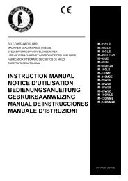
II. GENERAL INFORMATION1. CONSTRUCTION[a] <strong>KMD</strong>-<strong>201AA</strong>Water Supply TubeSpray GuideDrain ValveWater Supply InletAccess Valve(High Side)Spray TubeHot Gas ValveCondenserThermistorAccess Valve(Low Side)Expansion ValveFan MotorCompressorCube GuideWater TankPump MotorFloat SwitchControl BoxHarvest Water ValveFill Water ValveControl SwitchService SwitchFuse Holder (Fuse)DrierBin Control Switch3
[b] <strong>KMD</strong>-<strong>201AWA</strong>Water Supply TubeSpray GuideDrain ValveWater Supply InletAccess Valve(High Side)Spray TubeHot Gas ValveWater RegulatorThermistorAccess Valve(Low Side)Expansion ValveCondenserCompressorCube GuideDrierWater TankPump MotorFloat SwitchControl BoxHarvest Water ValveFill Water ValveControl SwitchService SwitchFuse Holder (Fuse)Bin Control Switch4
[e] NORMAL HARVEST CYCLELEDs 5, 6, and 8 are on. Comp continues to run, HGV remains open and HWV opens. Asthe evaporator warms, the thermistor reaches 9ºC. The control board then receives thethermistor’s 3.9kΩ signal and starts the harvest timer. HWV is open during harvest for amaximum of 6 minutes or the length harvest minus 0, 10, 30, or 50 seconds (adjustable byS1 dip switch 7 & 8), whichever is shorter. LED 8 goes off when HWV closes. PM energizesand runs for the last 0, 10, 30, or 50 seconds of harvest depending on S1 dip switch 7 & 8setting. LED 7 comes on when PM energizes. At the end of harvest, the control boardchecks for the position of LF/S and proceeds to the freeze cycle if it is closed or calls for a1-minute fill if it is open.The unit continues to cycle through [c], [d], and [e] sequence until the bin control is activatedand shuts the unit down. When the bin control is activated, the “POWER OK” LED flashes.Note: To prevent incomplete batches of ice from foaming on the evaporator, the controlboard will only shut down the machine within the first 5 minutes of the freeze cycleafter the thermistor temperature reaches 2 ºC. If ice pushes the bin control actuator in(open) after this minimum freeze period, the control board will allow the machine tocomplete the freeze cycle and the following harvest cycle before shutting down themachine.Legend: Comp–compressor; DV–drain valve; FMS–self-contained fan motor; FWV–fillwater valve; HGV–hot gas valve; HWV–harvest water valve; LF/S–lower floatswitch contacts; UF/S–upper float switch contacts; PM–pump motor6
<strong>KMD</strong>-<strong>201AA</strong>, <strong>201AWA</strong>Maximum harvest water valve time: 6 minutes(HWV time is 6 minutes of the length of harvestminus 0, 10, 30, or 50 sec. (S1 dip switch7 & 8), whichever is shorter. PM energizesand runs for the last 0, 10, 30, or 50 sec. ofharvest.)Maximum harvest time: 20 minutes0, 0,30,or 50 sec“H” board will have5 second delayHWV energized COMP energizedHGV energizedHWV continuesFWV de-energizedDV de-energizedLegend:COMP - compressorDV – drain valveFMS – self-contained fan motorFWV – fill water valveHGV – hot gas valveHWV – harvest water valveLF/S – lower float switch contactsPM – pump motorUF/S – upper float switch contactsMinimum freeze time: 5 minutesMaximum freeze time: freeze time settingLower float switch used to initiate waterTank refill (1 refill for <strong>KMD</strong>-201)Upper float switch used to terminatewater tank refill (1 minute maximum filltime)COMP continuesPM continuesFWV energized/de-energizedfor refill onlyFMS energizedHGV de-energized4. Drain CycleFactory set for every10 th cycle (S1 dipSwitch 5 & 6)Pump motor stopsfor 2 sec. and thenruns for 10/20 sec.(S1 dip switch 3 & 4)PM de-energizes 0/2 sec.,energizes for 10/20sec.COMP continuesDV energized/HGV energizedFMS de-energized7
3. CONTROL BOARD* A HOSHIZAKI exclusive solid-state control is employed in <strong>KMD</strong>-<strong>201AA</strong> and <strong>KMD</strong>-<strong>201AWA</strong>Crescent Cubers.* All models are pretested and factory-adjusted.1. Fragile, handle very carefully.2. A control board contains integrated circuits, which are susceptible to failuredue to static discharge. It is especially important to touch the metal part of theunit when handling or replacing the board.3. Do not touch the electronic devices on the board or the back of the board toprevent damage to the board.4. Do not change wiring and connections.5. Always replace the whole board assembly if it goes bad.6. Do not short out power supply to test for voltage.8
[a] CONTROL BOARD LAYOUT#4 Harvest Water Valve#5 Freeze Water Valve#1, 2, 3 Float Switch9
[b] FEATURESa) Maximum Water Supply Period - 6 minutesThe harvest water valve will be open during harvest for 6 minutes or the length of harvestminus 0, 10, 30, or 50 seconds (adjustable by S dip switch 7 & 8), whichever is shorter.b) Harvest Backup Timer and Freeze TimerThe harvest backup timer shuts down the icemaker if, for two cycles in a row, the harvestcycle takes more than 20 minutes to complete. The control board will signal this problemusing 2 beeps every 3 seconds.The freeze timer shuts down the icemaker if, for two cycles in a row, the freeze cycle takeslonger than the time specified to complete. The control board will signal this problem using 3beeps every 3 seconds. The time is factory set using S1 dip switch 9 & 10.The alarm reset button on the control board must be pressed with power on to reset either ofthese safeties.c) High Temperature SafetyThe temperature of the suction line in the refrigeration circuit is limited by the hightemperature safety. This protects the unit from excessively high temperatures. If theevaporator temperature rises above 53°C ± 4°C, the thermistor operates the safety.This shuts down the circuit and the icemaker automatically stops.The control board will signal this problem using 1 beep every 3 seconds. The alarm resetbutton on the control board must be pressed with power on to reset the safety.d) Low Water SafetyThe control board checks the position of the lower float switch at the end of the initial oneminute water fill cycle and at the end of each harvest cycle.If the lower float switch is in the up position (electrical circuit closed), the control boardchanges to the next cycle. If the lower float switch is in the down position (electrical circuitopen), the control board changes to additional one minute water fill cycles until water entersthe sump and the float switch closes. When the float switch closes, the control boardchanges to the next cycle. The unit will not start without adequate water in the sump. Thisserves as a low water safety to protect the water pump.For water-cooled model, if the condenser water supply is shut off, the unit is protected by thehigh-pressure switch.e) High Voltage and Low Voltage Cut-outsThe maximum and minimum allowable supply voltages of this icemaker are limited by thehigh voltage and low voltage cut-outs.If miswiring (especially on single 3 phase wire models) causes excessive voltage ( 294 Vac± 5% or more) on the control board, the high voltage cut-out shuts down the circuit in 3seconds and the icemaker automatically stops. The control board will signal this problemusing 7 beeps every 3 seconds.The icemaker also automatically stops in cases of insufficient voltage (184Vac ± 5% or less).The control board will signal this problem using 6 beeps every 3 seconds.When the proper supply voltage is resumed, the icemaker automatically starts runningagain.10
f) LED Lights and Audible Alarm SafetiesThe control board includes LED indicator lights, audible alarm safeties, and an output testfeature. The "POWER OK" LED indicates control voltage and will remain on unless a controlvoltage problem occurs. The “POWER OK” LED flashes continuously when the bin is fulland DV energizes for a maximum of 5 minutes to drain the water tank.At startup, a 5 second delay occurs to stabilize the circuit. LEDs 4 through 8 energize andsequence from initial startup as listed in the table below. Note that the order of the LEDsfrom the outer edge of the board is 5, 6, 8, 9, 4, 7. For more information, see "2.SEQUENCE OF OPERATION".HWVHWV, HGV,Comp5, 7 (and9 at refill)Comp, PM, FMS(FWV at refill)DV- drain valve; FMS-self-contained fan motor;WRV-water regulating valve;11
[c] CONTROLS AND ADJUSTMENTSa) Default Dip Switch SettingsThe dip switch is factory-adjusted to the following positions:<strong>KMD</strong>-<strong>201AA</strong>(50Hz)<strong>KMD</strong>-<strong>201AA</strong>(60Hz)<strong>KMD</strong>-<strong>201AWA</strong>(50Hz)<strong>KMD</strong>-<strong>201AWA</strong>(60Hz)<strong>KMD</strong>-<strong>201AA</strong>(50Hz)<strong>KMD</strong>-<strong>201AA</strong>(60Hz)<strong>KMD</strong>-<strong>201AWA</strong>(50Hz)<strong>KMD</strong>-<strong>201AWA</strong>(60Hz)Do not adjust the S2 dip switch. These must be left in the factory default position, or the unitwill not operate properly.b) Harvest Timer (S1 dip switch 1 & 2)Used for adjustment of the harvest timer. The harvest timer starts counting when thethermistor reads a certain temperature at the evaporator outlet.12
c) Drain Timer (S1 dip switch 3 & 4)Once every ten freeze cycles, the drain valve opens to drain the water tank for the timedetermined by the drain timer. These switches also determine the time to delay completionof a defrost cycle, i.e. the minimum defrost time.Do not change this setting, or the unit will not operate properly or produce high quality ice.T1: Time to drain the water tankT2: Harvest timer at drainDrain cycle always occurs on the 2nd harvest after startup. Then, depending on the drainfrequency control setting (dip switch 5 & 6), drain cycle occurs every cycle, or every 2nd, 5th,or 10th cycle.d) Drain Frequency Control (S1 dip switch 5 & 6)The water tank drains at the frequency set by the drain frequency control.The drain frequency control is factory-adjusted to drain the water tank every 10 cycles, andno adjustment is required. However, where water quality is bad and the icemaker needs adrain more often, the drain frequency can be adjusted as shown in the table below.e) Water Saver Timer (S1 dip switch 7 & 8)The water saver timer allows the water valve to close and the pump motor to circulate waterin the tank during the final part of harvest. The water valve is open during harvest for amaximum of 6 minutes or the length of harvest minus 0, 10, 30, or 50 seconds (determinedby the water saver timer setting), whichever is shorter. When the water valve closes, thepump motor energizes and runs for the time determined by the water saver timer setting.The water saver timer is factory-adjusted, and no adjustment is required.13
f) Freeze Timer (S1 dip switch 9 & 10)The freeze timer setting determines the maximum allowed freeze time to prevent possiblefreeze-up issues. Upon termination of freeze timer, machine initiates the harvest cycle. After2 consecutive timer terminations, machine will shut down, possibly indicating a problem.The freeze timer is factory adjusted, and no adjustment is required.Time(50/60Hz)(minutes)60/6060/50100/70120/100g) Pump-Out Pump Motor Delay (S2 dip switch 1)The pump-out pump motor delay determines whether or not the pump motor de-energizesfor 2 seconds before restarting at the beginning of a drain cycle.The pump-out pump motor delay is factory adjusted and no adjustment is required.h) Refill Counter (S2 dip switch 2, 3, & 4)Do not adjust. These must be left in the factory default position or the unit will not operateproperly. The <strong>KMD</strong>-<strong>201AA</strong> and <strong>KMD</strong>-<strong>201AWA</strong> refill 1 time.i) Factory Use (S2 Dip Switch 5)Must remain off.j) Anti-Slush Control (S2 dip switch 6)The anti-slush control helps prevent slushing during the freeze cycle on small icemakers.It is deactivated on the <strong>KMD</strong>-201 series.When activated, the thermistor located on the suction line checks for a 34 ºF (1 ºC)temperature as the evaporator cools. When 34 ºF (1 ºC) is reached, a 5.9 kΩ signal causesthe control board to de-energize the pump motor for 10 seconds.Do not adjust. This must be left in the factory default position or the unit will not operateproperly.14
[d] CONTROL BOARD CHECK PROCEDUREBefore replacing a control board that does not show a visible defect and that you suspect isbad, always conduct the following check procedure. This procedure will help you verify yourdiagnosis.1) Check the dip switch settings to assure that S1 dip switch 3, 4, 7, 8, 9, & 10 and S2 dipswitch 1 through 6 are in the factory default position. S1 dip switch 1, 2, 5, & 6 arecleaning adjustments and the settings are flexible.2) Move the control switch to the "ICE" position and check for proper control voltage. If the"POWER OK" LED is on, the control voltage is good. If the "POWER OK" LED is off,check the control transformer circuit. If no voltage is present, check the power supplycircuit.3) The output test button provides a relay sequence test. Make sure the control switch is inthe "ICE" position, then press the "OUTPUT TEST" button. The correct lighting sequenceshould be 5, 6, 7, 8, 9, 4. Some components (e.g., the compressor) will cycle during thetest. Each LED flashes three times in 5 seconds. LED 5 continues to flash while LED 6flashes. Following the output test sequence, the icemaker will resume normal operationbeginning with the 1 minute fill cycle.[e] CONTROL BOARD REPLACEMENTThe dip switches should be adjusted to the factory default settings as outlined in this manual.S2 dip switch 5 must remain off.4. HARVEST CONTROL – THERMISTORA thermistor (semiconductor) is used as a harvest control sensor and anti-slush sensor.The resistance varies depending on the suction line temperatures. The thermistor detectsthe temperature of the evaporator outlet to start the harvest timer or momentarily stop thepump motor during the freeze cycle. No adjustment is required. If necessary, check forresistance between thermistor leads, and visually check the thermistor mounting, located onthe suction line next to the evaporator outlet.Check a thermistor for resistance by using the followingprocedure:1) Disconnect the thermistor (orange wires) at the2-pin connector on the control box. See Fig. 1.2) Remove the thermistor. See "V. 17. THERMISTOR."3) Immerse the thermistor sensor portion in a glasscontaining ice and water for 2 or 3 minutes.4) Check for a resistance between thermistor leads.Normal reading is within 3.5 to 7 kΩ.Replace the thermistor if it exceeds thenormal reading.ThermistorConnector(orange wires)Bin ControlWires(black)Float SwitchConnector(red wires)15
5. FLOAT SWITCH[a] EXPLANATION OF OPERATIONThe float operates 2 switches within the float switch. The lower switch (black and blue wires)is used for low water safety protection, initiating the freeze cycle refill and terminating thefreeze cycle. The upper switch (black and red wires) is used to terminate the freeze cyclerefill only. Refill will last until the upper float switch closes or the 1 minute countdown timerends, whichever comes first.[b] CLEANINGDepending on local water conditions, scale may build up on the float, float switch shaft andinside the housing. Scale on the float or shaft can cause the float to stick causing erraticoperation. The float switch should be cleaned and checked before replacing.First, disconnect the float switch connector from the control box and remove the water tankand pump motor bracket together from the icemaker. Twist the mechanical lock inside of thepump motor bracket and remove the float switch. See "V. 15. FLOAT SWITCH." Removethe retainer clip from the shaft and slide the float off the shaft. Soak the switch assembly inice machine cleaner. Wipe down the shaft, float, housing with cleaning solution. See "VI.CLEANING AND MAINTENANCE INSTRUCTIONS."[c] FLOAT SWITCH CHECK PROCEDUREBefore replacing a float switch that you suspect is bad, make sure the float switch has beencleaned. This procedure will help you verify your diagnosis. The float switch has three wires.The black wire is common. The blue wire is for the lower float switch contact and the redwire is for the upper float switch contact.1) Disconnect the black float switch connector from the control box.2) Drain the reservoir water.3) Turn the control switch to "ICE".4) As water fills the reservoir, the float switch contacts should close. Check continuity of thelower float switch contacts using the black and blue wires and the upper float switchcontacts using the black and red wires. With the float positioned all the way up, both floatswitch contacts should be closed. If either float switch contact fails, the assembly shouldbe replaced.5) Turn the control switch to "OFF".6) Drain the reservoir water.7) As water drains, the float switch contacts should open. Check continuity of the upper floatswitch contacts using the black and red wires and the lower float switch contacts usingthe black and blue wires. With the float positioned all the way down, both float switchcontacts should be open. If either float switch contact fails, the assembly should bereplaced.8) Reconnect the black connector to the control box when finished.16
6. BIN CONTROLThis machine uses a lever-actuated proximity switch (mechanical bin control) to control theice level in the storage bin. No adjustment is required.[a] EXPLANATION OF OPERATIONThe bin control is connected to the K1 connector (pins 4 & 5) on the control board.When the bin control is calling for ice (proximity switch closed; "POWER OK" LED on), thecontrol board continues icemaking operations. When the bin control is activated in the binfull position (proximity switch open; "POWER OK" LED flashing), the control board drainsand shuts down the unit. However, to prevent incomplete batches of ice from forming on theevaporator, the control board will only shut down the machine during the freeze cycle beforethe five minute timer expires. The five minute timer starts counting down when thethermistor temperature reaches 2°C. If, during the freeze cycle, ice pushes in the lever afterthe five minute timer expires, the control board will allow the machine to complete the freezecycle and the following harvest cycle before shutting down the machine.[b] BIN CONTROL CHECK PROCEDURE1) Clear any ice away from the bin control.2) Make sure the control switch is in the "ICE" position.3) Check that the "POWER OK" LED on the control board is on.4) Activate the bin control actuator (press the actuator in). Check that the "POWER OK" LEDflashes.5) Disconnect the bin control at the 2-pin connector attached to the black wires coming fromthe K1 connector (pins 4 & 5) on the control board.6) Check for continuity across the bin control leads. When calling for ice, the bin controlproximity switch should be closed. If open, replace the bin control. Activate the bin controlactuator (press the actuator in), check for continuity across the bin control leads. The bincontrol proximity switch should be open. If closed, replace the bin control.7) Reconnect the 2-pin connector. Allow the machine to cycle into the freeze cycle. In thefirst 5 minutes of the freeze cycle, activate the bin control actuator (press the actuator in).The "POWER OK" LED should flash and the machine should turn off. If not, replace thecontrol board.17
7. SWITCHESTwo different control switches are used for operation of <strong>KMD</strong>-<strong>201AA</strong> and <strong>KMD</strong>-<strong>201AWA</strong>.These switches are referred to as the "control switch" and the "service switch" and arelocated on the control box.[a] CONTROL SWITCHThis switch is used to place the machine into one of three modes: “OFF” (center position),“ICE” (upper position), and “SERVICE” (lower position).[b] SERVICE SWITCHWhen the control switch is placed in the “SERVICE” position, power is supplied to theservice switch. The service switch can be used to perform two functions: draining the tank(“DRAIN” = lower position) and washing the icemaking compartment (“WASH” or“CIRCULATE” = upper or center position). Both the “WASH” and “CIRCULATE” positionsactivate the same function of washing the icemaking compartment. The service switch isactivated in any of the three positions when the power is supplied to the pump motor.1) “DRAIN”<strong>KMD</strong>-<strong>201AA</strong> and <strong>KMD</strong>-<strong>201AWA</strong> employ the pump-out drain system. When the serviceswitch is active and placed in the lower position, power is supplied to the pump motor anddrain valve.2) “WASH” or “CIRCULATE”When the service switch is active and placed in the upper or center position, power issupplied to the pump motor. This function is to clean the evaporator plate.18
III. TECHNICAL INFORMATION1. WATER CIRCUIT AND REFRIGERANT CIRCUIT19
2. WIRING DIAGRAM20
3. TIMING CHART21
IV. SERVICE DIAGNOSIS1. 10-MINUTE DIAGNOSTIC PROCEDUREThe 10 minute check out procedure is basically a sequence check which can be used atunit start-up or for system diagnosis. Using this check out procedure will allow you todiagnose electrical system and component failures in approximately 10 minutes undernormal operating conditions of 21°C or warmer air and 10°C or warmer watertemperatures. Before conducting a 10 minute checkout, check for correct installation,proper voltage per unit nameplate and adequate water supply. As you go through theprocedure, check to assure the components energize and de-energize correctly. If not,those components and controls are suspect.1) Turn power off and access the control box. Clear any ice from the bin control actuatorlocated in the bin.2) Turn power on and place the control switch in the "ICE" position. A 5 second delay occurs.The "POWER OK" LED on the control board comes on. If the "POWER OK" LED isflashing (indicating a full bin), check the bin control. See "II. 6. [b] BIN CONTROL CHECKPROCEDURE."3) One Minute Fill Cycle – The harvest water valve is energized. After 1 minute, the controlboard checks the float switch. If the lower float switch is closed, the unit cycles to harvest.If closed, continue to step 4. If the lower float switch is open, the unit repeats the 1 minutefill cycle until water enters and the lower float switch closes (low water safety protectionduring initial start up and at the end of each harvest). Diagnosis: If the water valve doesnot open, check for no supply voltage at water valve terminals, bad coil, or pluggedscreen or external filter (no water flow). If unit fails to start harvest, check for open floatswitch or bad 1 minute timer in board.4) Initial Harvest Cycle – The harvest water valve remains energized, contactor coilenergizes to start the compressor (and fan motor on a remote condenser unit), and thehot gas valve energizes. The evaporator warms and the thermistor senses 48 °F (9°C).The control board then receives the thermistor's 3.9 kΩ signal and turns operation ofharvest over to the harvest timer. The timer completes counting (1 to 3 minutes). The unitthen cycles to freeze. Diagnosis: Check if compressor is running, hot gas valve is open,harvest water valve still open. Average harvest cycle at factory setting is 2 to 4 minutes.How long does initial harvest last? 1.5 minutes after initial harvest begins, touch thecompressor discharge line. Is it hot? If not, check refrigerant pressures and compressoroperation. If it is hot, touch the inlet line to the evaporator. Is it hot? If it is hot and thefreeze cycle is not starting, check the harvest timer adjustment, the thermistor for opencircuit, the discharge line temperature, compressor efficiency, and if the hot gas valve isfully open.5) Freeze Cycle – The compressor remains energized, pump motor, (line valve if applicable),and fan motor energize. The harvest water valve and hot gas valve de-energize. The unitis held in freeze by a 5 minute short cycle protection timer which starts after thethermistor temperature reaches 2°C. After this period, the freeze cycle operation istransferred to the float switch for freeze termination. The lower float switch activates(open) 2 times during the course of a freeze cycle; the first is for refill, the second is forfreeze termination. After the second lower float switch activation, the control boardterminates freeze and initiates harvest.22
a. Lower Float Switch 1st Activation: Refill– The refill can occur at any time during thefreeze cycle (1 refill per cycle). As ice builds the water level drops in the reservoir and thelower float switch activates (opens). LED 5 comes on and the control board energizes thefill water valve. The fill water valve remains energized until the upper float switch closes orthe 1 minute fill timer terminates, whichever comes first.b. Lower Float Switch 2nd Activation:The unit is held in freeze by a 5 minute short cycleprotection timer which starts after the thermistor temperature reaches 2°C. After the 1stlower float switch activation and refill, ice continues to form and the water level drops inthe reservoir. When the lower float switch activates (opens) a second time, the freezecycle terminates (freeze can only be terminated on the second activation of the lower floatswitch and after the minimum freeze period). Diagnosis: During the minimum freezeperiod, confirm that the evaporator temperature drops, compressor, fan motors and pumpmotor are energized and that the hot gas valves, harvest water valve and fill water valve(except during refill) are de-energized and not bypassing. Make sure the expansionvalves are operating properly and, in cold conditions. Make sure that the drain water valveis not leaking by (water flowing down the potable drain). Check for proper unit pressures,or an inoperative compressor. Disconnect the 3-pin float switch connector from the controlbox. 15 seconds after disconnecting the 3-pin float switch connector, LED 5 comes onand refill begins. Connect the 3-pin float switch connector back on the control box. Whenthe refill is finished (LED 5 goes off), disconnect the 3-pin float switch connector again. If 5or more minutes have elapsed in the freeze cycle, the unit should switch out of the freezecycle. After the unit switches out of freeze, reconnect the 3-pin float switch connector tothe control box. If the unit remains in freeze with the float switch disconnected, replace theboard. To check the float switch, see "II. 5. [c] FLOAT SWITCH CHECK PROCEDURE."Note: Normal freeze cycle will last 20 to 40 minutes depending on model and conditions.Cycle times and pressures should follow performance data provided in this manual.6) Drain Cycle – The compressor remains energized, the hot gas valve energizes, the fanmotor de-energizes. The drain valve and pump motor energize, allowing water to drainfrom the tank for 20 seconds. This removes contaminants from the water tank.Diagnosis: If the drain valve does not open, check the circuit. Check for proper voltage. Ifwater does not drain out, check and clean the tubing at the drain valve and then checkand clean the valve assembly.7) Normal Harvest Cycle – same as the initial harvest cycle – Return to step 4.Note: Unit continues to cycle until bin control is satisfied or power is turned off. (The draincycle can be adjusted to occur every cycle, or every 2, 5, or 10 cycles. The factorydefault is every 10 cycles.) The unit always restarts at the 1 minute fill cycle.23
2. DIAGNOSTIC CHARTS[a] NO ICE PRODUCTION2. See "II. 6. [b] Bin ControlCheck Procedure."5. See chart [a] [7].24
1. See "II. 4. Harvest Control- Thermistor."1. See "II. 3. [d] ControlBoard Check Procedure."1. See "II. 3. [d] ControlBoard Check Procedure."25
1. See "II. 3. [d] ControlBoard Check Procedure."1. See "II. 3. [d] ControlBoard Check Procedure."1. See "II. 3. [d] ControlBoard Check Procedure."1. See "II. 3. [d] ControlBoard Check Procedure."1. See "II. 3. [d] ControlBoard Check Procedure."26
1. Adjust or replace. See "V.9. Adjustment of WaterRegulating Valve."[b] EVAPORATOR IS FROZEN UP1. See "II. 3. [d] ControlBoard Check Procedure."1. See "V. 17. Thermistor."1. See "II. 3. [c] Controls andAdjustments, b) HarvestTimer."27
1. See "II. 3. [d] ControlBoard Check Procedure."[c] LOW ICE PRODUCTIONa) See chart [b] [1] and check float switch, fill and harvest water valves, controlboard, water pump, spray tubes, evaporator, and expansion valve.b) See chart [a] [1] and check dirty air filter or condenser, ambient or watertemperature, refrigerant charge, water pressure, and condenser waterregulating valve (water-cooled model only).a) See chart [b] [2] and check evaporator, water supply line, harvest water valve,ambient and/or water temperature, line valve (if applicable), thermistor, controlboard, and hot gas valve.[d] ABNORMAL ICEa) Ice Cube Guide,Water Tank,Deflector28
a) See chart [b] [1] & [3] and check float switch, fill and harvest water valves, controlboard, spray tubes, water system, refrigerant charge, and expansion valve.[e] OTHER1. See "II. 6. [b] Bin ControlCheck Procedure."c) Ice Cube Guide,Water Tank,Deflector29
V. REMOVAL AND REPLACEMENT1. SERVICE FOR REFRIGERANT LINES[a] SERVICE INFORMATION1) Allowable Compressor Opening Time and Prevention of Lubricant Mixture [R404A]The compressor must not be opened more than 15 minutes in replacement or service. Donot mix lubricants of different compressors even if both are charged with the samerefrigerant, except when they use the same lubricant.2) Treatment for Refrigerant Leak [R404A]If a refrigerant leak occurs in the low side of an ice maker, air may be drawn in. Even if thelow side pressure is higher than the atmospheric pressure in normal operation, acontinuous refrigerant leak will eventually lower the low side pressure below theatmospheric pressure and will cause air suction. Air contains a large amount of moisture,and ester oil easily absorbs a lot of moisture. If an ice maker charged with R404A haspossibly drawn in air, the drier must be replaced. Be sure to use a drier designed forR404A.3) Handling of Handy Flux [R404A]Repair of the refrigerant circuit requires brazing. It is no problem to use the same handyflux that has been used for the current refrigerants. However, its entrance into therefrigerant circuit should be avoided as much as possible.4) Oil for Processing of Copper Tubing [R404A]When processing the copper tubing for service, wipe off oil, if any used, by using alcohol orthe like. Do not use too much oil or let it into the tubing, as wax contained in the oil will clogthe capillary tubing.5) Service Parts for R404ASome parts used for refrigerants other than R404A are similar to those for R404A. Butnever use any parts unless they are specified for R404A because their endurance againstthe refrigerant have not been evaluated. Also, for R404A, do not use any parts that havebeen used for other refrigerants. Otherwise, wax and chlorine remaining on the parts mayadversely affect R404A.6) Replacement Copper Tubing [R404A]The copper tubes currently in use are suitable for R404A. But do not use them if oily inside.The residual oil in copper tubes should be as little as possible. (Low residual oil typecopper tubes are used in the shipped units.)30
7) Evacuation, Vacuum Pump and Refrigerant Charge [R404A]Never allow the oil in the vacuum pump to flow backward. The vacuum level and vacuumpump may be the same as those for the current refrigerants. However, the rubber hoseand gauge manifold to be used for evacuation and refrigerant charge should be exclusivelyfor R404A.8) Refrigerant Leak CheckRefrigerant leaks can be detected by charging the unit with a little refrigerant, raising thepressure with nitrogen and using an electronic detector. Do not use air or oxygen insteadof nitrogen for this purpose, or rise in pressure as well as in temperature may causeR404A to suddenly react with oxygen and explode. Be sure to use nitrogen to preventexplosion.[b] REFRIGERANT RECOVERYThe icemaker unit is provided with refrigerant access valves. Using proper refrigerantpractices, recover the refrigerant from the access valves and store it in an approvedcontainer. Do not discharge the refrigerant into the atmosphere.[c] EVACUATION AND RECHARGE1) Attach a vacuum pump to the system. Be sure to connect charging hoses to both highand low-side access valves.2) Turn on the vacuum pump. Open the service manifold valves. Never allow the oil in thevacuum pump to flow backwards.3) Allow the vacuum pump to pull down to a 760 mmHg vacuum. Evacuating perioddepends on pump capacity.4) Close the low-side valve and high-side valve on the service manifold.5) Disconnect the vacuum pump and attach a refrigerant service cylinder to the high-sideline. Remember to loosen the connection and purge the air from the hose. For air-cooledand water-cooled models, see the nameplate for the required refrigerant charge.6) A liquid charge is recommended for charging an R-404A system. Invert the servicecylinder and place it on scales. Open the high-side valve on the service manifold.7) Allow the system to charge with liquid until the proper charge weight is met.8) If necessary, add any remaining charge to the system through the low-side. Use athrottling valve or liquid dispensing device to add the remaining liquid charge through thelow-side access port with the unit running.9) Close the service manifold valves and disconnect the service manifold hoses.10) Cap the access valves to prevent a possible leak.31
2. BRAZINGNote: All brazing connections inside the bin are clear coated. Sandpaper the brazingconnections before unbrazing the components. Use a good abrasive cloth to removethe coating.3. COMPRESSOR1) Turn off the power supply.2) Remove the panels and water tank. See "V. 14. WATER TANK."32
3) Recover the refrigerant and store it in an approved container.4) Remove the terminal cover on the compressor and disconnect the compressor wiring.5) Remove the hold-down bolts, washers, and rubber grommets.6) Remove the discharge and suction pipes.7) Remove the compressor. Unpack the new compressor package.8) Attach the rubber grommets of the prior compressor.9) Place the compressor in position and secure it using the bolts and washers.10) Remove the drier, then place the new drier in position.11) Remove plugs from the suction, discharge, and process pipes.12) Braze all fittings while purging with nitrogen gas flowing at a pressure of 20 to 30 kPa.13) Use an electronic leak detector or soap bubbles to check for leaks. Add a trace ofrefrigerant to the system (if using an electronic leak detector), and then raise thepressure using nitrogen gas (970 kPa). DO NOT use R-404A as a mixture withpressurized air for leak testing.14) Evacuate the system, and charge it with refrigerant. For air-cooled and water-cooledmodels, see the nameplate for the required refrigerant charge.15) Connect the terminals and replace the terminal cover in its correct position.16) Replace the panels and water tank in their correct positions.17) Turn on the power supply.Note: <strong>Hoshizaki</strong> recommends that Compressor starting electrics are always replaced at thesame time as the Compressor.4. DRIER1) Turn off the power supply.2) Remove the panels.3) Recover the refrigerant and store it in an approved container.4) Remove the Drier Holder, if any, and pull the Drier toward you for easy service.33
5) Remove the Drier using brazing equipment.6) Braze the new Drier, with the arrow on the Drier in the direction of the refrigerant flow.Use nitrogen gas at a pressure of 20 to 30 kPa when brazing tubings. Braze in an AccessValve using a tee if necessary.7) Check for leaks using nitrogen gas (970 kPa) and soap bubbles.8) Evacuate the system and charge it with refrigerant (see "V. 1. [c] EVACUATION ANDRECHARGE").9) Refit the panels in their correct positions.10) Turn on the power supply.Note: Always use a Drier of the correct capacity and refrigerant type.5. HOT GAS VALVE1) Turn off the power supply.2) Remove the panels.3) Recover the refrigerant and store it in an approved container.4) Disconnect the Hot Gas Valve leads.5) Remove the screw and the Solenoid Coil.6) Remove the valve and Drier using brazing equipment.7) Braze the new Hot Gas Valve with nitrogen gas flowing at a pressure of 20 to 30 kPa.34
8) Install the new Drier (see "V. 4. DRIER").9) Check for leaks using nitrogen gas (970 kPa) and soap bubbles.10) Evacuate the system and charge it with refrigerant (see "V. 1. [c] EVACUATION ANDRECHARGE").11) Attach the Solenoid Coil to the valve body, and secure it with the screw.12) Connect the lead wires.13) Refit the panels in their correct positions.14) Turn on the power supply.6. EXPANSION VALVE1) Turn off the power supply.2) Remove the panels.3) Recover the refrigerant and store it in an approved container.4) Remove the insulation and the expansion valve bulb on the suction line.5) Remove the expansion valve cover and disconnect the expansion valve. Place the newexpansion valve in position.6) Remove the drier, then place the new drier in position.7) Braze all fittings while purging with nitrogen gas flowing at a pressure of 20 to 30 kPa.8) Use an electronic leak detector or soap bubbles to check for leaks. Add a trace ofrefrigerant to the system (if using an electronic leak detector), and then raise thepressure using nitrogen gas (970 kPa). DO NOT use R-404A as a mixture withpressurized air for leak testing.35
9) Evacuate the system, and charge it with refrigerant. For air-cooled and water-cooledmodels, see the nameplate for the required refrigerant charge.10) Attach the expansion valve bulb to the suction line in the same location as the previousbulb. The bulb should be at the 12 o'clock position on the tube. Be sure to secure thebulb with the clamp and holder and to insulate it.11) Place the expansion valve cover in position.12) Replace the panels in their correct positions.13) Turn on the power supply.7. EVAPORATOR1) Turn off the power supply.2) Remove the panels and the front and top insulation.3) Recover the refrigerant and store it in an approved container.4) Remove the spray tubes. Remove the insulation at the "U" shaped notch where therefrigeration tubing passes through the molded chassis.5) Disconnect the evaporator tubing.6) Remove the pop rivets securing the evaporator, then lift out the evaporator.7) Install the new evaporator.8) Remove the drier, then place the new drier in position.9) Braze all fittings while purging with nitrogen gas flowing at a pressure of 20 to 30 kPa.10) Use an electronic leak detector or soap bubbles to check for leaks. Add a trace ofrefrigerant to the system (if using an electronic leak detector), and then raise thepressure using nitrogen gas (970 kPa). DO NOT use R-404A as a mixture withpressurized air for leak testing.11) Evacuate the system, and charge it with refrigerant. For air-cooled and water-cooledmodels, see the nameplate for the required refrigerant charge.12) Replace the removed parts in the reverse order of which they were removed.13) Replace the insulation and the panels in their correct positions.14) Turn on the power supply.36
8. WATER REGULATING VALVE – WATER-COOLED MODEL ONLY1) Turn off the power supply.2) Remove the panels.3) Close the condenser water supply line shut-off valve, then open the condenser watersupply line drain valve.4) Attach a compressed air or carbon dioxide supply to the condenser water supply linedrain valve.5) Open the water regulating valve by using a screwdriver to pry up on the spring retainerunderneath the spring. While holding the valve open, blow out the condenser using thecompressed air or carbon dioxide supply until water stops coming out.6) Recover the refrigerant and store it in an approved container.7) Disconnect the capillary tube at the condenser outlet.8) Disconnect the flare-connections of the valve.9) Remove the screws and the valve from the bracket.10) Install the new valve.11) Remove the drier, then place the new drier in position.12) Braze all fittings while purging with nitrogen gas flowing at a pressure of 20 to 30 kPa..13) Use an electronic leak detector or soap bubbles to check for leaks. Add a trace ofrefrigerant to the system (if using an electronic leak detector), and then raise thepressure using nitrogen gas (970 kPa). DO NOT use R-404A as a mixture withpressurized air for leak testing.14) Evacuate the system, and charge it with refrigerant. See the nameplate for the requiredrefrigerant charge.15) Connect the flare-connections.16) Close the condenser water supply line drain valve, then open the condenser watersupply line shut-off valve.17) Check for water leaks.18) Replace the panels in their correct positions.37
19) Turn on the power supply.9. ADJUSTMENT OF WATER REGULATING VALVE– WATER-COOLED MODEL ONLYThe water regulating valve (also called "water regulator") is factory-adjusted. No adjustmentis required under normal use. Adjust the water regulator, if necessary, using the followingprocedures.1) Prepare a thermometer to check the condenser drain temperature. Attach a pressuregauge to the high-side line of the system.2) Five minutes after a freeze cycle starts, confirm that the thermometer reads 40 ºC to 46ºC. If it does not, rotate the adjustment screw by using a flat blade screwdriver until thetemperature is in the proper range. See Fig. below. Next, check that the referencepressure is in the range indicated in the Head Pressure table in the Performance Datasection. If it is not in the proper range, verify the refrigerant charge.3) Check that the condenser drain temperature is stable.10. FAN MOTOR1) Turn off the power supply.2) Remove the panels.3) Loosen the two screws securing the Fan Blade Cover, then remove it.4) Disconnect the Connector of the Fan Motor lead.5) Loosen the far side of the two screws and remove the near side of the two screwssecuring the Fan Motor Bracket and slide out towards you. To prevent deformation, donot hit the Fan on the Condenser or other parts.6) Install the new Fan Motor in the reverse order of the removal procedure.7) Replace the panels in their correct positions.8) Turn on the power supply.38
Screw(Loosen)Screw(Remove)ScrewFan MotorFan Blade CoverFan Motor Bracket11. PUMP MOTOR1) Turn off the power supply.2) Remove the panels and front insulation.3) Disconnect the Connector of the Pump Motor lead.4) Remove the thumbscrew securing the Pump Motor.5) Remove the Hose Band connecting the Discharge Hose.6) Slide the Pump Motor at right slightly and lift it up towards you.Hose BandThumbscrewDischarge HosePump Motor39
7) Remove the Hose Band connecting the discharge outlet and pull off the Rubber Hose.8) Install the new motor in the reverse order of the removal procedure.9) Replace the panels and front insulation in their correct positions.10) Turn on the power supply.12. WATER VALVE1) Turn off the power supply.2) If replacing the harvest and/or fill water valve, close the icemaker water supply lineshut-off valve. Open the icemaker water supply line drain valve.3) Remove the panels.4) Disconnect the tubing attached to the valve. If replacing the harvest and/or fill water valve,loosen the fitting nut. Be careful not to lose the washer.5) Disconnect the terminals from the valve.6) Remove the bracket and valve from the unit.7) Install the new valve. Replace the removed parts in the reverse order of which they wereremoved. If replacing the harvest and/or fill water valve, make sure the washer is in placein the fitting nut.8) If replacing the harvest and/or fill water valve, close the icemaker water supply line drainvalve. Open the icemaker water supply line shut-off valve.9) Turn on the power supply.10) Check for leaks.11) Replace the panels in their correct positions.13. DRAIN VALVE1) Turn off the power supply.2) Close the water supply tap.3) Remove the panels.4) Disconnect the Connector of the Drain Valve lead.5) Remove the Hose Clamps at the inlet and outlet sides.6) Remove the Rubber Hoses at the inlet and outlet sides.40
7) Remove the two mounting screws.8) Install the new valve in the reverse order of the removal procedure.9) Open the water supply tap.10) Plug in the icemaker or connect the power source.11) Check for leaks.12) Refit the panels in their correct positions.14. WATER TANK1) Remove the front panel, then remove the front insulation2) Loosen the two thumbscrews securing the Pump Motor Bracket3) Move the control switch to the "SERVICE" position. Move the service switch to the"DRAIN" position.4) Let the icemaker run for 2 minutes.5) Move the control switch to the "OFF" position.6) Turn off the power supply.7) Disconnect the Pump Motor and Float Switch connector from the side of the control box.8) Keep pushing up the snapping tab at the right side of the Pump Motor Bracket.9) Pull out the Water Tank, Cube Guide, Pump Motor Bracket, Pump Motor and Float Switchtogether.41
10) Install the new water tank in the reverse order of the removal procedure.11) Refit the panels in their correct positions.12) Turn on the power supply.15. FLOAT SWITCH1) Remove the Pump Motor Bracket. See "V. 14. WATER TANK."2) Pull up the Pump Motor Bracket from the Water Tank.3) Flip over the Pump Motor Bracket assembly, then twist off the Float Switch and pull outtowards you.42
4) Install the new float switch in the reverse order of the removal procedure.5) Refit the panels in their correct positions.6) Turn on the power supply.16. BIN CONTROL SWITCH1) Remove the Water Tank. See "V. 14. WATER TANK."2) Disconnect the Connector of the Bin Control Switch lead (black).3) Pull out the Bin Control Switch Tab outside and slide the Bin Control Switch towards you.Bin Control Switch Tab4) Take out the Bin Control.5) Install the new bin control switch.6) Pass the bin control connector through the hole from the bottom to the top of the unit.7) While pulling up the bin control lead, hook the bin control on the right side interior wall.Then push the bin control up against the bottom of the unit, and slide to the back until itsnaps in place. Make sure the slotted holes at the right side of the bin control aresecurely placed on the collars at the bottom of the unit.43
8) Connect the bin control connector to the side of the control box.9) Replace the water tank, cube guide, pump motor bracket, pump motor and float switch intheir correct positions until they snap in place.10) Secure the pump motor bracket with the two thumbscrews.11) Reconnect the pump motor connector and float switch connector.12) Replace the front insulation and front panel in their correct positions.13) Turn on the power supply.17. THERMISTOR1) Turn off the power supply.2) Remove the panels.3) Disconnect the Connector of the Thermistor lead (orange).4) Remove the Ties, Insulation, Thermistor Holder, and Thermistor in this order.5) Remove the old sealant from the Thermistor Holder and Suction Pipe.6) Wipe off any moisture or condensation from the Suction Pipe surfaces.7) Press a tube of the sealant KE 60RTV, manufactured by Shin-Etsu Silicones, to therecess of the Thermistor Holder. Slowly squeeze the sealant out of the tube and spread itsmoothly in the recess. Do not use any sealant other than the above.8) Attach the new Thermistor in position on the Suction Pipe and press down the ThermistorHolder over the Thermistor. Be careful not to damage the Thermistor lead. Cover theparts with the Insulation and secure them with the Ties. Keep the Thermistor inside theThermistor Holder. After the Thermistor Holder is fitted, do not pull the Thermistor lead tomove the Thermistor.44
9) Refit the removed parts in the reverse order of the removal procedure.10) Turn on the power supply.18. CONTROL BOX1) Turn off the power supply.2) Remove the front panel.3) Remove the one mounting screw, and pull the Control Box Cover.4) Remove the two mounting screws, and pivot the Control Box to the left side slightly andpull the Control Box towards you if needed.ScrewsControl Box CoverControl BoxScrew45
5) Refit the removed parts in the reverse order of the removal procedure.Note: After replacing the components inside the Control Box, connect and tie the wiresproperly in their correct position. Especially make sure that the Harness does notpress the Push Buttons on the Control Board.Control SwitchService SwitchControl BoardFuseFuse HolderPush ButtonsTransformerStarterRun CapacitorStart CapacitorCapacitor for Pump MotorMagnetic Contactor[a] CONTROL & SERVICE SWITCH1) Disconnect the Tab Terminals and remove the Nut securing the Power Switch.2) Install the new Switch in the reverse order of the removal procedure.3) To prevent miswiring, check the terminal numbers and lead wire colors with the WiringLabel.[b] FUSE1) Use a phillips head screwdriver to remove the Fuse Holder Cap and take out the Fuse.2) Install the new Fuse in the reverse order of the removal procedure.[c] FUSE HOLDER1) Disconnect the Tab Terminal and remove the Nut securing the Fuse Holder.2) Install the new Fuse Holder in the reverse order of the removal procedure.46
[d] CONTROL BOARD1) Disconnect all the Connectors.2) Remove the four Board Supports secured to the Control Box to release the ControlBoard.3) Install the new Control Board in the reverse order of the removal procedure.4) Check the Dip Switch for proper setting.5) When reconnecting the Connectors, do not push them too hard. The Control Board maybe damaged.[e] MAGNETIC CONTACTOR1) Disconnect the Tab Terminals, remove the mounting screw or pull the tub of bracket torelease the Magnetic Contactor, and lift off the Magnetic Contactor.2) Install the new Magnetic Contactor in the reverse order of the removal procedure.[f] CONTROL BOARD TRANSFORMER1) Disconnect the Connectors and Closed End Connectors connecting the Control Board.(The Tie securing the harness may be removed. But be careful not to break the leadwires.)2) Remove the mounting screws.3) Install the new Transformer in the reverse order of the removal procedure.[g] STARTER1) Disconnect the Terminals, remove the mounting screw.2) Install the new Starter in the reverse order of the removal procedure.3) To prevent miswiring, check the terminal numbers and lead wire colors with the WiringLabel.[h] RUN CAPACITOR1) Disconnect the Terminals on the Starter and remove the Nut securing the Run Capacitor.2) Install the new Run Capacitor in the reverse order of the removal procedure.3) To prevent miswiring, check the terminal numbers and lead wire colors with the WiringLabel.[i] START CAPACITOR1) Disconnect the Terminals on the Starter and remove the Nut securing the Run Capacitor.47
2) Install the new Run Capacitor in the reverse order of the removal procedure.3) To prevent miswiring, check the terminal numbers and lead wire colors with the WiringLabel.[j] CAPACITOR FOR PUMP MOTOR1) Disconnect the Tab Terminals, remove the screw.2) Install the new Capacitor in the reverse order of the removal procedure.19. SPRAY TUBE, WATER SUPPLY TUBE, SPRAY GUIDE1) Turn off the power supply.2) Remove the panels and front insulation.3) Remove the Hose Band connecting the Hose.4) Push the Tabs on both sides of the Spray Tube to release the Spray Tube.5) Pull the Spray Tube towards you.TabsHose BandWater Supply Tube(under Spray Tube)Spray TubeHoseHose Band6) The Spray Tube is easily cleanable by removing the black rubber caps on the ends.7) Remove the Hose Band connecting the Water Supply Tube.8) Pull the Water Supply Tube towards you.9) Remove the Top Insulation.10) The Spray Guide is located under the Water Supply Tube. Pull off the Spray Guide fromthe Evaporator.48
Spray Guide11) Refit the removed parts in the reverse order of the removal procedure. Check for waterleaks.49
VI. CLEANING AND MAINTENANCE INSTRUCTIONS1. CLEANING[a] CLEANING PROCEDURE1) Dilute approximately 9.5 fl. oz. (281 ml) of recommended cleaner <strong>Hoshizaki</strong> “Scale Away”or “LIME-A-WAY” (Economics Laboratory, Inc.) with 1.8 gallon (6.8 lit.) of water.2) Remove all ice from the evaporator and the storage bin/dispenser unit.Note: To remove cubes on the evaporator, turn off the power supply and turn it on after 3minutes. The harvest cycle starts and the cubes will be removed from the evaporator.3) Turn off the power supply.4) Remove the front panel and move the control switch to the “SERVICE” position. Move theservice switch to the “DRAIN” position.5) Replace the front panel in its correct position and turn on the power supply for 2 minutes.6) Turn off the power supply.50
7) Remove the front panel then remove the front insulation (the large insulation panel in frontof the evaporator) by lifting up the panel slightly and pulling it towards you.8) In bad or severe water conditions, clean the float switch as described below. Otherwise,continue to step 9.a. Loosen the two thumbscrews securing the pump motor bracket.b. Disconnect the discharge hose.c. Disconnect the pump motor connector and the float switch connector from the side of thecontrol box.d. Keep pushing up the snapping tab at the right side of the pump motor bracket.e. Pull out the water tank, cube guide, pump motor bracket, pump motor and float switchtogether.f. Remove the pump motor bracket securing the pump motor and the float switch. Removethe float switch from the pump motor bracket.51
g. Wipe down the float switch housing, shaft and float with cleaning solution. Rinse the partsthoroughly with clean water.h. Replace the float switch in its correct position.i. Replace the removed parts in the reverse order of which they were removed.9) Pour the cleaning solution into the water tank.10) Move the service switch to the "WASH" position.11) Replace the front insulation and the front panel in their correct positions.12) Turn on the power supply to start the washing process.13) Turn off the power supply after 30 minutes.14) Remove the front panel.15) Move the service switch to the "DRAIN" position.16) Replace the front panel in its correct position and turn on the power supply for 2 minutes.17) Turn off the power supply and remove the front panel.18) Move the control switch to the "ICE" position.19) Replace the front panel in its correct position.20) Turn on the power supply to fill the water tank with water.21) Turn off the power supply after 3 minutes.22) Remove the front panel.23) Move the control switch to the "SERVICE" position. Move the service switch to the"WASH" position.24) Replace the front panel in its correct position.25) Turn on the power supply to rinse off the cleaning solution.26) Turn off the power supply after 5 minutes.27) Remove the front panel.28) Move the service switch to the "DRAIN" position.29) Replace the front panel in its correct position and turn on the power supply for 2 minutes.30) Turn off the power supply.52
31) Remove the front panel.32) Repeat steps 18 through 31 three more times to rinse thoroughly.Note: If you do not sanitize the icemaker, go to step 14 in "Sanitizing Procedure."[b] SANITIZING PROCEDURE – FOLLOWING CLEANING PROCEDURE1) Dilute a 5.25% sodium hypochlorite solution (chlorine bleach) with water (addapproximately 0.9 fl. oz. (27 ml) to 1.8 gal. (6.8 lit.) of water).2) Remove the front insulation.3) Pour the sanitizing solution into the water tank.4) Move the service switch to the "WASH" position.5) Replace the front insulation and the front panel in their correct positions.6) Turn on the power supply to start the sanitizing process.7) Turn off the power supply after 15 minutes.8) Remove the front panel.9) Move the service switch to the "DRAIN" position.10) Replace the front panel in its correct position and turn on the power supply for 2 minutes.11) Turn off the power supply.12) Remove the front panel.13) Repeat steps 18 through 31 in "[a] CLEANING PROCEDURE" two times to rinsethoroughly.14) Move the control switch to the "ICE" position.15) Replace the front panel in its correct position.16) Clean the storage bin/dispenser unit liner using a neutral cleaner. Rinse thoroughly aftercleaning.17) Turn on the power supply to start the automatic icemaking process.2. MAINTENANCE53
[a] STAINLESS STEEL EXTERIORTo prevent corrosion, wipe the exterior occasionally with a clean, soft cloth. Use a dampcloth containing a neutral cleaner to wipe off oil or dirt build up.[b] STORAGE BIN AND SCOOP* Wash your hands before removing ice. Use the plastic scoop provided (bin accessory).* The storage bin/dispenser unit is for ice use only. Do not store anything else in the storagebin/dispenser unit.* Clean the scoop and the storage bin/dispenser unit liner using a neutral cleaner. Rinsethoroughly after cleaning.[c] AIR FILTERS (AIR-COOLED MODEL ONLY)Plastic mesh air filters remove dirt and dust from the air, and keep the condenser fromgetting clogged. As the filters get clogged, the icemaker’s performance will be reduced.Check the filters at least twice a month. When clogged, use warm water and a neutralcleaner to wash the filters.[d] CONDENSER (AIR-COOLED MODEL ONLY)Check the condenser once a year, and clean if required by using a brush or vacuum cleaner.More frequent cleaning may be required depending on the location.3. PREPARING THE ICEMAKER FOR LONG STORAGEWhen the icemaker is not used for two or three days, it is sufficient to only move the controlswitch to the “OFF” position, unless the icemaker will be at sub-freezing temperatures.1. On water-cooled model only, first remove the water from the water-cooledcondenser:1) Turn off the power supply and remove the front panel.54
2) Move the control switch on the control box to the "OFF" position.3) Wait 3 minutes.4) Move the control switch to the "ICE" position.5) Replace the front panel in its correct position and turn on the power supply.6) Allow 5 minutes for the icemaker to fill with water and the water pump to start operating.7) Close the condenser water supply line shut-off valve.8) Open the condenser water supply line drain valve.9) Allow the line to drain by gravity.10) Attach compressed air or carbon dioxide supply to the condenser water supply line drainvalve.11) Blow the condenser out using compressed air or carbon dioxide until water stopscoming out.12) Close the condenser water supply line drain valve.2. Remove the water from the icemaker water supply line:1) Turn off the power supply and remove the front panel.2) Move the control switch on the control box to the "OFF" position.3) Close the icemaker water supply line shut-off valve and open the icemaker water supplyline drain valve.4) Allow the line to drain by gravity.5) Attach compressed air or carbon dioxide supply to the icemaker water supply line drainvalve.6) Move the control switch to the "ICE" position.7) Replace the front panel in its correct position and turn on the power supply.8) Blow the icemaker water supply line out using compressed air or carbon dioxide.3. Drain the water tank:1) Turn off the power supply and remove the front panel.2) Move the control switch to the "SERVICE" position and move the service switch to the"DRAIN" position.3) Replace the front panel in its correct position and turn on the power supply for 2 minutes.55
4) Turn off the power supply and remove the front panel.5) Move the control switch to the "OFF" position.6) Replace the front panel in its correct position.7) Remove all ice from the storage bin/dispenser unit, and clean the storage bin/dispenserunit.8) Close the icemaker water supply line drain valve.56