HRE-70B Service manual.pdf - Hoshizaki
HRE-70B Service manual.pdf - Hoshizaki
HRE-70B Service manual.pdf - Hoshizaki

You also want an ePaper? Increase the reach of your titles
YUMPU automatically turns print PDFs into web optimized ePapers that Google loves.
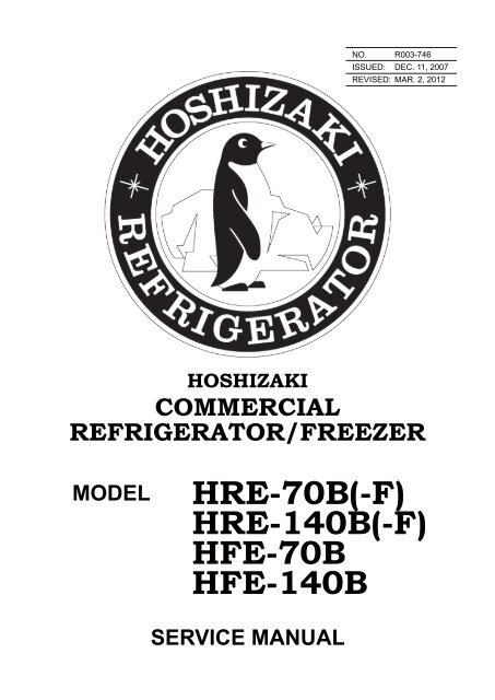
NO. R003-746ISSUED: DEC. 11, 2007REVISED: MAR. 2, 2012HOSHIZAKICOMMERCIALREFRIGERATOR/FREEZERMODEL<strong>HRE</strong>-<strong>70B</strong>(-F)<strong>HRE</strong>-140B(-F)HFE-<strong>70B</strong>HFE-140BSERVICE MANUAL
CONTENTSPAGEI. GENERAL INFORMATION---------------------------------------------------------------------------11. SAFETY INSTRUCTIONS-------------------------------------------------------------------------12. DIMENSIONS/SPECIFICATIONS----------------------------------------------------------------3[a] <strong>HRE</strong>-<strong>70B</strong>-------------------------------------------------------------------------------------------3[b] <strong>HRE</strong>-140B------------------------------------------------------------------------------------------4[c] HFE-<strong>70B</strong>--------------------------------------------------------------------------------------------5[d] HFE-140B------------------------------------------------------------------------------------------6[e] <strong>HRE</strong>-<strong>70B</strong>-F-----------------------------------------------------------------------------------------7[f] <strong>HRE</strong>-140B-F---------------------------------------------------------------------------------------8II. TECHNICAL INFORMATION-----------------------------------------------------------------------91. WIRING DIAGRAM----------------------------------------------------------------------------------9[a] <strong>HRE</strong>-<strong>70B</strong>-------------------------------------------------------------------------------------------9[b] <strong>HRE</strong>-140B---------------------------------------------------------------------------------------- 10[c] HFE-<strong>70B</strong>------------------------------------------------------------------------------------------ 11[d] HFE-140B---------------------------------------------------------------------------------------- 12[e] <strong>HRE</strong>-<strong>70B</strong>-F--------------------------------------------------------------------------------------- 13[f] <strong>HRE</strong>-140B-F------------------------------------------------------------------------------------- 142. REFRIGERATION CIRCUIT--------------------------------------------------------------------- 153. ENERGY SAVING FEATURES----------------------------------------------------------------- 16[a] FRAME HEATER ENERGIZING CONTROL-------------------------------------------- 16[b] INTERIOR DC FAN MOTOR---------------------------------------------------------------- 17[c] CONTROLLER BOARD---------------------------------------------------------------------- 17[d] REFRIGERATION UNIT---------------------------------------------------------------------- 174. ELECTRONIC CONTROLS---------------------------------------------------------------------- 18[a] SET POINT TEMPERATURE--------------------------------------------------------------- 18[b] CABINET TEMPERATURE DIFFERENTIAL-------------------------------------------- 18[c] DEFROST CYCLE----------------------------------------------------------------------------- 18[d] DEFROST COMPLETION TEMPERATURE-------------------------------------------- 18[e] TEMPERATURE DISPLAY CYCLE-------------------------------------------------------- 18[f] COMPRESSOR SOFT START------------------------------------------------------------- 19[g] HIGH PRESSURE SWITCH---------------------------------------------------------------- 19[h] CHECKING AND ADJUSTING SET POINT TEMPERATURE---------------------- 20[i] MANUAL DEFROST--------------------------------------------------------------------------- 20[j] FRAME HEATER SETTING----------------------------------------------------------------- 20[k] CANCELLING SOFT START---------------------------------------------------------------- 21[l] ERROR CODES-------------------------------------------------------------------------------- 21[m] CONTROLLER BOARD MODEL SETTING-------------------------------------------- 215. TIMING CHART------------------------------------------------------------------------------------- 22[a] STARTUP - CONTROL----------------------------------------------------------------------- 22[b] DEFROST---------------------------------------------------------------------------------------- 236. BUTTON OPERATION---------------------------------------------------------------------------- 25[a] OPERATION PANEL LAYOUT-------------------------------------------------------------- 25[b] BASIC OPERATION--------------------------------------------------------------------------- 25[c] CHECKING AND DELETING ERROR RECORDS------------------------------------ 25i
[d] ADJUSTING OPERATION SETTINGS--------------------------------------------------- 26[e] MODEL SETTING AT CONTROLLER BOARD REPLACEMENT----------------- 28III. SERVICE DIAGNOSIS---------------------------------------------------------------------------- 301. ERROR CODES------------------------------------------------------------------------------------ 302. FLOWCHART---------------------------------------------------------------------------------------- 333. COMPONENTS------------------------------------------------------------------------------------- 354. CONTROLLER BOARD-------------------------------------------------------------------------- 37[a] SERVICING CONTROLLER BOARD----------------------------------------------------- 37[b] CHECKING THERMISTOR------------------------------------------------------------------ 38IV. REMOVAL AND REPLACEMENT OF COMPONENTS----------------------------------- 391. CONTROLLER BOARD AND THERMISTOR----------------------------------------------- 39[a] REMOVAL OF CONTROL BOX------------------------------------------------------------ 39[b] REPLACEMENT OF CONTROL BOX---------------------------------------------------- 39[c] THERMISTOR---------------------------------------------------------------------------------- 392. RELAY BOX------------------------------------------------------------------------------------------ 41[a] POWER SUPPLY BOARD------------------------------------------------------------------- 413. REFRIGERATION CIRCUIT--------------------------------------------------------------------- 41[a] COMPRESSOR-------------------------------------------------------------------------------- 41[b] CONDENSER AND DRIER------------------------------------------------------------------ 42[c] EVAPORATOR---------------------------------------------------------------------------------- 42[d] CONDENSER FAN MOTOR---------------------------------------------------------------- 43[e] DEFROST HEATER AND THERMAL FUSE (HFE)----------------------------------- 434. EVAPORATION TANK----------------------------------------------------------------------------- 44[a] DRAIN TANK HEATER----------------------------------------------------------------------- 44[b] THERMOSTAT---------------------------------------------------------------------------------- 45[c] THERMAL FUSE------------------------------------------------------------------------------- 455. AIR DUCT-------------------------------------------------------------------------------------------- 45[a] AIR DUCT---------------------------------------------------------------------------------------- 45[b] INTERIOR FAN MOTOR--------------------------------------------------------------------- 466. DOOR PARTS--------------------------------------------------------------------------------------- 46[a] DOOR HANDLE-------------------------------------------------------------------------------- 46[b] HINGE SPACER-------------------------------------------------------------------------------- 47[c] LIFT HINGE-------------------------------------------------------------------------------------- 47[d] DOOR GASKET-------------------------------------------------------------------------------- 477. CONDENSER CLEANING PAN---------------------------------------------------------------- 488. OPTIONAL PARTS--------------------------------------------------------------------------------- 48[a] HINGE KIT--------------------------------------------------------------------------------------- 48[b] GASTRONOME PAN RAIL------------------------------------------------------------------ 49ii
I. GENERAL INFORMATION1. SAFETY INSTRUCTIONSThe following instructions contain important safety precautions and should be strictlyobserved. The terms used here are defined as follows:WARNING: There is a possibility of death or serious injury to the service person anda third party or the user due to improper service operations or defects inserviced products.CAUTION:There is a possibility of injury to the service person and a third party or theuser or damage to their property* due to improper service operations ordefects in serviced products.* The term “damage to their property” here refers to extensive damage to householdeffects, houses and pets.WARNING1. Always ask the user to keep children away from the work area. They may be injured bytools or disassembled products.2. When there is no need to energize the unit during disassembly or cleaning, be sure tounplug the unit or disconnect the main power supply before servicing the unit to preventelectric shocks.3. If the unit must be energized for inspection of the electric circuit, use rubber gloves toavoid contact with any live parts resulting in electric shocks.4. Keep the following in mind when servicing the refrigeration circuit:(1) Be sure to recover the refrigerant. Do not discharge it into the atmosphere. It willaffect the environment.(2) Check for any flames in the vicinity, and ensure good ventilation.(3) If the refrigerant should leak in servicing, immediately put out any fire used in thevicinity.(4) When unbrazing the refrigeration circuit connections, check that the circuit iscompletely evacuated. The refrigerant may produce a poisonous gas when comingin contact with an open flame.(5) Do not braze in an enclosed room to prevent carbon monoxide poisoning.(6) In case of a refrigerant leak, locate and repair the leaking part completely beforerecharging the refrigerant and checking for further leaks. If the leaking part cannot1
e located, be sure to check again for further leaks after recharging the refrigerant.Leaked refrigerant may produce a poisonous gas when coming in contact with anopen flame of a gas cooking stove or a fan heater.(7) Before servicing, check the surface temperature of the refrigeration circuit toprevent a burn.5. Keep the following in mind when making electrical connections:(1) Check for proper earth connections, and repair if necessary to prevent electricshocks.(2) Always use service parts intended for the applicable model for replacement ofdefective parts. Use proper tools to secure the wiring. Otherwise abnormaloperation or trouble may occur and cause electric leaks or fire.(3) Check for proper part installations, wiring conditions and soldered or solderlessterminal connections to avoid fire, heat or electric shocks.(4) Be sure to replace damaged or deteriorated power cords and lead wires to preventfire, heat or electric shocks.(5) Cut-off lead wires must be bound using closed end connectors or the like, with theirclosed ends up to avoid entrance of moisture that could lead to electric leaks orfire.(6) After servicing, always use a megohmmeter (500V DC) to check for the insulationresistance of at least 1 megohm between the live part (attachment plug) and thedead metal part (earth terminal).(7) Do not service the electrical parts with wet hands to prevent electric shocks.(8) The capacitors used for the compressor and other components may be under highvoltage and should be discharged properly before servicing.CAUTION1. After servicing, follow the instructions below:(1) Always check the unit for proper operation before finishing services.(2) Be sure to reassemble the parts completely. Loose assembly of such partsas control box cover may cause entrance of vermins resulting in a short circuitbetween terminals and possible ignition.2
2. DIMENSIONS/SPECIFICATIONS[a] <strong>HRE</strong>-<strong>70B</strong>3
[b] <strong>HRE</strong>-140B4
[c] HFE-<strong>70B</strong>5
[e] <strong>HRE</strong>-<strong>70B</strong>-F7
[f] <strong>HRE</strong>-140B-F8
II. TECHNICAL INFORMATION1. WIRING DIAGRAM[a] <strong>HRE</strong>-<strong>70B</strong>9
[b] <strong>HRE</strong>-140B10
[c] HFE-<strong>70B</strong>11
[d] HFE-140B12
[e] <strong>HRE</strong>-<strong>70B</strong>-F13
[f] <strong>HRE</strong>-140B-F14
2. REFRIGERATION CIRCUITRefrigerant:HFC-134a (<strong>HRE</strong> series)HFC-404A (HFE series)15
3. ENERGY SAVING FEATURES[a] FRAME HEATER ENERGIZING CONTROLThe Frame Heater is energized intermittently to keep the Front Frame surfaces at theoptimum temperature for preventing condensation. As the optimum surface temperaturedepends on the ambient temperature, the ratio between ON time and OFF time isdetermined by the difference between the ambient temperature (measured by theTemperature Sensor built in the Controller Board) and the cabinet temperature (measuredby the Interior Thermistor). This duty ratio has eight patterns and is updated every twominutes.The duty ratios are sorted into seven levels (<strong>HRE</strong> series) or six levels (HFE series)depending on the difference between the ambient and cabinet temperatures. The higherlevels at the same ambient and cabinet temperatures mean the higher duty ratios. Theunit is factory adjusted to level 2.The user is allowed to choose between levels 2 and 3 only, and service persons betweenlevels 0 - 6 (<strong>HRE</strong> series) or 1 - 6 (HFE series).[Reference]Level 2: No condensation at ambient temperature 35°C, relative humidity 70%Level 3: No condensation at ambient temperature 35°C, relative humidity 80%Duty Ratio ON time OFF timeAmbient temp - cabinet temp<strong>HRE</strong> seriesHFE series(%) (sec) (sec) Level 3 Level 2 Level 3 Level 212.5 15 105 5 or less 14 or less 9 or less 23 or less25 30 90 5 - 10 14 - 19 9 - 16 23 - 3037.5 45 75 10 - 14 19 - 24 16 - 23 30 - 3750 60 60 14 - 19 24 - 28 23 - 30 37 - 4462.5 75 45 19 - 24 28 - 33 30 - 37 44 - 5275 90 30 24 - 28 33 - 37 37 - 44 52 - 5987.5 105 15 28 - 33 37 - 41 44 - 52 59 - 66100 120 0 33 or more 41 or more 52 or more 66 or more[Relations between duty ratio and ambient and cabinet temperature differences]<strong>HRE</strong> series duty ratioLevel 0: Constantly OFFLevel 2: Factory adjustmentLevel 6: Constantly ON16
HFE series duty ratioLevel 2: Factory adjustmentLevel 6: Constantly ONThe heater control reduces the power consumption, and the less heat invasion into thecabinet improves the refrigeration unit operating efficiency, resulting in significant energysaving effects.[b] INTERIOR DC FAN MOTORThe highly efficient DC brushless motor reduces the power consumption of the motor bodyfrom 21 W to 4 W with the same output. Also, the lower heating value prevents cabinettemperature rise and improves the refrigeration unit operating efficiency, resulting in energysaving effects.[c] CONTROLLER BOARDTo save energy, <strong>HRE</strong> series stops energizing the Frame Heater for a maximum of 15minutes during a defrost cycle (HFE series has an energizing control).[d] REFRIGERATION UNITProvided with the best matched Capillary Tubes for refrigerant control.Plastic Unit Base and Unit Frame in shape to minimize heat input/output.Corrosion resistant aluminum Evaporator with boehmite treated and clear coated surfaces.17
4. ELECTRONIC CONTROLS[a] SET POINT TEMPERATURE (mean temperaturebetween compressor ON and OFF temperatures)Set Point TemperatureOff-cycle defrost (<strong>HRE</strong> series):Heater defrost (<strong>HRE</strong>-F series):Heater defrost (HFE series):0 to +16°C-6 to +12°C-25 to -7°CInterior ThermistorTemperature3.7 KTimeCompressorONOFF[b] CABINET TEMPERATURE DIFFERENTIAL3.7 K (from “set point temp - 2.0 K” to “set point temp + 1.7 K”)Note: On the Controller Board only. Actual differential may be 4 - 6 K.[c] DEFROST CYCLEEvery 6 hours (from the beginning of a cycle to the beginning of the next cycle)[d] DEFROST COMPLETION TEMPERATUREOff-cycle defrost (<strong>HRE</strong> series):Heater defrost (<strong>HRE</strong>-F series):Heater defrost (HFE series):+3°C+30°C+20°C[e] TEMPERATURE DISPLAY CYCLEThe Temperature Display Window renews its cabinet temperature display every 30seconds. The display remains the same for 30 seconds even if the actual temperaturechanges in the meantime. During a defrost cycle, the Temperature Display Windowindicates “dF”.18
[f] COMPRESSOR SOFT START1) StartupPower ON3 min20 secCompressorCondenser Fan MotorInterior Fan MotorCabinet Temp. DisplayONOFFONOFFONOFFWhen the power supply is turned on, the Temperature Display Window shows the cabinettemperature, but the Compressor and Condenser Fan Motor start up with a 3 minute delay.Then, the Interior Fan Motor starts up 20 seconds later.This delay is intended to minimize the difference between the high-side and low-sidepressures and to reduce the load on the Compressor so that it can start easily in case of ashort (especially instantaneous) power failure.2) Normal ControlInterior ThermistorSet PointCompressorCondenser Fan MotorONOFF2.5 min 2.5 minWhen the Compressor turns off during normal control, it has a mandatory 2.5 minute delaybefore startup. For example, if the Compressor turns off by its Thermistor and the Dooris opened immediately after (causing the cabinet temperature to immediately exceed therestart temperature), the Compressor will still not start until 2.5 minutes have passed sinceits shutdown.[g] HIGH PRESSURE SWITCHPressure SwitchSet PointCompressorCondenser Fan MotorONOFFMin 6 min6 min19
All models are provided with a High Pressure Sensor to monitor the condensingtemperature. If the high-side pressure rises to operate the High Pressure Sensor, theCompressor will not restart for at least 6 minutes to protect itself.HFE series is also equipped with a backup High Pressure Switch. If the CondensingTemperature Thermistor becomes defective, the High Pressure Switch operates to stopand protect the Compressor.[h] CHECKING AND ADJUSTING SET POINT TEMPERATUREPress the Set Point Button to display the set point temperature on the Temperature DisplayWindow. To change the set point temperature, hold down the Set Point Button and pressthe Temperature Control Button.Frame Heater ButtonReset ButtonManual Defrost ButtonSet Point ButtonTemperature Control ButtonTemperature Display Window[i] MANUAL DEFROSTWhen the Manual Defrost Button is pressed for more than 5 seconds, the unit will start a<strong>manual</strong> defrost cycle. The unit will start repeating automatic defrost cycles 6 hours afterthe Manual Defrost Button is pressed.To cancel the <strong>manual</strong> defrost cycle, turn off the power supply. Wait for at least 30 secondsbefore turning the power back on.[j] FRAME HEATER SETTINGThe duty ratio of the Frame Heater is controlled. The unit is factory adjusted to the dutyratio level 2 with the lamp on the Frame Heater Button off. If condensation occurs at theinstallation site, press the Frame Heater Button for more than 3 seconds to change theduty ratio level from 2 to 3. Then, the lamp on the Frame Heater Button will illuminate.To de-energize the Frame Heater (<strong>HRE</strong> series only), see “6. BUTTON OPERATION”.20
[k] CANCELING SOFT STARTTo cancel the “soft start” (3 minute delay), turn on the power supply while pressing the SetPoint Button. The Compressor and Condenser Fan Motor will start at the same time after10 seconds.When the soft start is cancelled, the illuminated seven segment LED on the TemperatureDisplay Window changes to the model setting number. To resume the cabinet temperaturedisplay, press the Set Point Button again or wait for 30 seconds.Note: If the power supply is turned off while the Compressor is running and immediatelyturned back on to cancel the soft start, the high-side and low-side pressures cannotbe equalized, often resulting in Compressor starting failure. Do not cancel the softstart for at least 2.5 minutes after the power supply is turned off.[l] ERROR CODESIn case of trouble, the Temperature Display Window will alternately flash every secondbetween one of the following error codes and the cabinet temperature. See “III. 1. ERRORCODES” for further details.Code Error Code ErrorE1 Cabinet Temperature Too High E7 Condenser CloggedE2 Cabinet Temperature Too Low E8 Defrost Thermistor DefectiveE3 Defrost Cycle Too Long E9 Clog Thermistor DefectiveE4 Abnormal High-Side Pressure EA EEPROM Write ErrorE5 Interior Thermistor Defective Ed EEPROM Verify ErrorIn case of error, an external output (12V DC) function is available for connection with abuzzer.[m] CONTROLLER BOARD MODEL SETTINGTo indicate the Controller Board model setting number on the Temperature DisplayWindow, turn on the power supply while pressing the Set Point Button.Note: Proper model setting is required when the Controller Board is replaced. See “6.BUTTON OPERATION” for further details.21
5. TIMING CHART[a] STARTUP - CONTROL<strong>HRE</strong>, HFE series(2) (3)3 min 20 secPower SupplyTemp DisplayFrame Heater(1)CompressorCondenserFan MotorInteriorFan MotorInteriorThermistor TempSet Point Temp + 1.7 KEvaporationSignalEvaporation PanHeaterEvaporation PanThermostatSet Point TempSet Point Temp - 2.0 K(4)(1) Frame Heater ControlIntermittent energization by difference between ambient and cabinet temperatures.Energization time has 8 patterns (duty ratio 12.5% - 100%).Duty ratio is updated every 2 min, except previous ratio is maintained during defrostcycle.(2) Standby at StartupOnly temperature indication is available for 3 min (not a sign of failure).(3) Interior Fan Motor Delay at StartupInterior Fan Motor and Frame Heater will not operate for 20 sec after Compressorstarts.Interior Fan Motor OFF after End of ControlInterior Fan Motor will not operate for 2 min.(4) Evaporation Signal<strong>HRE</strong> series:Cam Timer, for 7 min every 8 hrs<strong>HRE</strong>-F series, HFE series: Defrost start signal, every 6 hrs22
[b] DEFROST<strong>HRE</strong> series (Off-cycle defrost)Frame Heater20 sec OFFUpdate (1) Maintainduty ratio Max 15 min OFF duty ratio Update duty ratioCompressorCondenserFan MotorInteriorFan MotorDefrost (Interior)Thermistor TempDetects end of cycle (3°C)Temp DisplayDefrost(until Thermistor detects)Temp Temp and "dF" alternately TempHFE series (2)Update (3) 20 sec OFFduty ratio Maintain previous duty ratio Update duty ratioFrame HeaterCompressorCondenserFan MotorInteriorFan MotorDefrost HeaterDuct HeaterDefrostThermistor TempDetects end of cycle (20°C)Temp DisplayDefrost Drain Interior Display(until Thermistor detects) 10 min FM delay delay5 min 3 minTemp "dF" Temp23
<strong>HRE</strong>-F series (Heater defrost) (2)Frame Heater(3)20 sec OFFUpdate (1)Maintainduty ratio Max 15 min OFF duty ratio Update duty ratioCompressorCondenserFan Motor(4) 15 sec ONInteriorFan MotorDefrost HeaterDefrost (Interior)Thermistor TempDetects end of cycle (30°C)Temp DisplayDefrost Drain Interior Display(until Thermisto 5.5 min FM delay delaydetects) 5 min 3 minTemp "dF" TempSubject of Control Description Model PurposeFrame Heater (1) Remains OFF for max 15 min after <strong>HRE</strong> Save energydefrost cycle starts (until Interior FanMotor delay ends at longest)(2) Remains OFF for 20 sec afterCompressor starts following drain cycleHFE Improve Compressorstartability(3) Duty ratio is not updated and maintainsprevious ratio after defrost cycle startsand until Interior Fan Motor delay endsHFE PreventcondensationInterior FanMotor(4) Remains ON for 15 sec afterCompressor starts following drain cycle<strong>HRE</strong>-F Improve Compressor(Heater startabilitydefrost)24
6. BUTTON OPERATION[a] OPERATION PANEL LAYOUTFrame Heater ButtonReset ButtonManual Defrost ButtonSet Point ButtonTemperature Control ButtonTemperature Display Window[b] BASIC OPERATIONCondition Button Pressing Duration FunctionConstant Set Point — Indicate set point temp while depressedConstant Set Point— Change set point tempTemp ControlConstant Manual Defrost Long (5 sec) Start <strong>manual</strong> defrostError Reset Short Cancel error code indication(not available on some errors)With more than one error, press to cancelone by oneConstant Frame Heater Long (3 sec) Change Frame Heater levelHigh: Lamp ON(raise default duty ratio by 1 level)Low: Lamp OFF (default)[c] CHECKING AND DELETING ERROR RECORDSTo check error records:1) Press the Reset Button and Set Point Button at the same time for 5 seconds (ResetButton first). The Temperature Display Window will show “F0”.25
2) Press the Temperature Control Buttons until “F6” appears.3) Press the Reset Button to flash the error records in the order of occurrence. “– –” willappear if no error is recorded.4) Press the Manual Defrost Button to return to “F6”.5) Repeat step 1) to indicate the cabinet temperature.To delete error records:1) Follow steps 1) to 3) above.2) Press the Reset Button for 5 seconds to flash “– –”.3) Follow steps 4) to 5) above.Note: 1. Do not perform any other button operation until the Temperature Display Windowshows from “F0” to “FF” before showing “F6”. Otherwise, the basic settings willchange and may cause malfunction. In case of misoperation, see the list in “[d]ADJUSTING OPERATION SETTINGS” to restore the default settings.2. Repeated errors are stored as one record. For example, errors in the order ofE7, E7, E7, E4, E7 are recorded as E7, E4, E7.[d] ADJUSTING OPERATION SETTINGSThe following settings are adjustable:(1) Set Point Temperature(2) Frame Heater Duty Ratio Level(3) Soft Start Cancelation(4) Automatic Defrost Cycle Interval(5) E1 (Cabinet Temperature Too High) Occurrence Timing(6) E2 (Cabinet Temperature Too Low) Occurrence Timing(7) Buzzer Output (External Output)(8) Defrost Backup TimerExcept (1) and (2), the default settings are optimal to meet the specifications. To preventunexpected malfunction, do not adjust them unless necessary.(1) Set Point TemperatureHold down the Set Point Button, use the Temperature Control Buttons to adjust to thedesired set point temperature, and release the Set Point Button.(2) Frame Heater Duty Ratio LevelIf condensation occurs on the Front Frame:Press the Frame Heater Button for 3 seconds to illuminate the lamp on the button (the dutyratio is raised by 1 level).26
To freely select the Frame Heater duty ratio level from 1 to 6:1) Hold down the Frame Heater Button and press the Set Point Button. The TemperatureDisplay Window will show “2”.2) Hold down the Set Point Button and use the Temperature Control Buttons to indicate “1”- “6”. The higher levels at the same ambient and cabinet temperatures mean the higherduty ratios (level 6 is constantly ON).To keep the Frame Heater OFF (<strong>HRE</strong> series only):1) Hold down the Frame Heater Button and press the Set Point Button. The TemperatureDisplay Window will show “2”.2) Hold down the Set Point Button, use the Temperature Control Button to indicate “0”,and release the Set Point Button.(3) Soft Start Cancelation (for immediate startup of Compressor)Hold down the Set Point Button and turn on the power supply. The Compressor will startafter 10 seconds. This operation is available only once when the power supply is turnedon.Note: If the power supply is turned off while the Compressor is running and immediatelyturned back on to cancel the soft start, the high-side and low-side pressures cannotbe equalized, often resulting in Compressor starting failure. Do not cancel the softstart for at least 2.5 minutes after the power supply is turned off.(4) - (9)These adjustments are available by the following button operation including the errorrecords checking and deleting procedures:1) Press the Reset Button and Set Point Button at the same time for 5 seconds (ResetButton first). The Temperature Display Window will show “F0”.2) Press the Temperature Control Buttons until the desired function code (F0 - FF)appears.3) Press the Set Point Button to indicate the current setting (except “F6”).4) Hold down the Set Point Button and use the Temperature Control Buttons to indicatethe desired value. Adjust to the default setting when the correct value is not known.5) Release the Set Point Button.6) Repeat step 1) or wait for more than 1 minute. The Temperature Display Window willshow the cabinet temperature.27
Code Function Indication with Set Point ButtonF0 Automatic Defrost CycleInterval– –: No automatic defrost cycle3: Every 3 hrs6: Every 6 hrs (default setting)8: Every 8 hrs12: Every 12 hrs24: Every 24 hrsLong defrost cycle intervals may increase frostingF3 E1 (Cabinet Temp Too High)Occurrence TimingF4F6FbFCE2 (Cabinet Temp Too Low)Occurrence TimingChecking/Deleting ErrorRecordsBuzzer Output (ExternalOutput)Defrost Backup Timer (durationuntil forced de-energization ofDefrost Heater)and cause inadequate cooling.0: Immediate occurrence (no error record)For remote alarm checking.Return to original setting after checking.1: After 1 hr2: After 2 hrs (default setting)3: After 3 hrs0: Immediate occurrence (no error record)For remote alarm checking.Return to original setting after checking.1: After 1 hr (default setting)1) Press Reset Button to indicate error records (E1 -EE) every 0.5 sec for 1 sec each (max 8 recordsper compartment).2) Press Reset Button for more than 5 sec to deleteerror records.3) Press Manual Defrost Button to indicate “F6”.AL: Buzzer output for all errors (default setting)1.2: Buzzer output for E1 and E2 only– –: No backup (no E3 occurrence)0.4: 24 min0.7: 40 min1: 60 min (default setting)1.3: 80 min1.7: 100 min2: 120 minLong duration until backup (or no backup) maycause fuse to blow when Defrost Heater isenergized for a long time.[e] MODEL SETTING AT CONTROLLER BOARD REPLACEMENTThe replacement Controller Boards are shipped without model setting. To preventmalfunction and inadequate cooling, be sure to finish model setting before use.Some buttons on the replacement Controller Boards may be unnecessary for somemodels. Proper model setting will disable those buttons.28
To set the mode setting number:1) Turn off the power supply.2) Hold down the two Temperature Control Buttons and turn on the power supply. TheTemperature Display Window will show “01”.Note: This is not the preset model number.3) Use the Temperature Control Buttons to indicate the desired model number.Note: Do not select “00”, or further settings will be made unavailable. When “00” isselected by mistake, turn off the power supply and go back to step 2).4) Press the Reset Button for more than 3 seconds. The Temperature Display Window willflash “rc”.5) Press the Reset Button again for more than 3 seconds. The Temperature DisplayWindow will flash “oF”.6) Turn off the power supply.To check the model setting number:1) Hold down the Set Point Button and turn on the power supply.2) The Temperature Display Window will illuminate and show the model setting number.(The Compressor will start 10 seconds after this button operation.)Model setting number:1D (<strong>HRE</strong> series: Off-cycle defrost)0D (<strong>HRE</strong>-F series: Heater defrost)29 (HFE series)29
III. SERVICE DIAGNOSIS1. ERROR CODESIn case of trouble, the Temperature Display Window indicates the cabinet temperature and the applicable error code alternatelyevery 1 second (even in a defrost cycle).Except EA and Ed, there is no need to restart the unit to reset errors.Code Error Description Possible Cause ResetComponent ConditionE1 Cabinet TempToo HighE2 Cabinet TempToo LowE3 Defrost CycleToo Long(HFE seriesonly)E4 AbnormalHigh-SidePressureCabinet temp stays 10K aboveset point for 2 hrs (availableafter power is turned on andcabinet temp drops to lowerlimit).Cabinet temp stays 5K belowset point for 1 hr.Defrost Heater remainsenergized for 1 hr and is forciblyde-energized.High pressure is detected 5or more times in 1 hr (4 timeswithin 1 hr after 1st detection).Clog Thermistor* See table below for set point.- Compressor control error- Compressor defective- Refrigeration circuitdefective (ex. gas leak)- Interior Thermistordefective- Compressor control error- Interior Thermistordefective- Heater control error- Heater defective- Thermal Fuse circuitopen- Defrost Thermistordefective- Condenser Fan Motordefective- Dirty Air Filter- Clog Thermistordefective- Ambient temp toohigh- Gap between Doorand cabinet- Door opened toofrequently- Too many warmitems inside- Ambient temp too low- Too many frozenitems inside- Door opened toofrequently, causingexcessive Evaporatorfrosting- Ambient temp toohighPress Reset Button.Automatically resetswhen cabinet tempdrops to lower limit.Press Reset Button.Automatically resetswhen cabinet temprises to upper limit.Press Reset Button (noautomatic reset).Press Reset Button (noautomatic reset).30
Code Error Description Possible Cause ResetComponent ConditionE5 InteriorThermistorDefectiveE7 CondenserCloggedE8 DefrostThermistorDefectiveE9 ClogThermistorDefectiveEA EEPROMWrite ErrorEd EEPROMVerify ErrorInterior Thermistor circuit isopen or shorted for 10 min ormore.Note: For either reason,Compressor will operatecontinuously. Be careful withfrozen refrigerator compartment.Surface temp of Condenserpiping (U bend at center oroutlet) stays above set point for5 min.* See table below for set point.Defrost Thermistor circuit isopen or shorted for 10 min ormore.Clog Thermistor circuit is openor shorted for 10 min or more.Abnormal value is detectedin EEPROM reading/writing(Controller Board hardwareproblem).Inconsistency is detectedin setting information used(Controller Board softwareproblem).- Interior Thermistorcircuit open, connectorunplugged- Interior Thermistor circuitshorted, dusty connector- Condenser Fan Motordefective- Dirty Air Filter- Defrost Thermistorcircuit open, connectorunplugged- Defrost Thermistor circuitshorted, dusty connector- Clog Thermistor circuitopen, connectorunplugged- Clog Thermistor circuitshorted, dusty connector- Controller Boarddefective- Controller Boardmalfunction- Controller Boarddefective- Controller Boardmalfunction- Ambient temp toohighPress Reset Buttonafter removing cause(no automatic reset).Automatically resetswhen Clog Thermistorsenses temp lowerthan set point (ResetButton will not work).Automatically resetsafter cause is removed(Reset Button will notwork).Automatically resetsafter cause is removed(Reset Button will notwork).Turn power off andback on after 30 sec(no automatic reset).Turn power off andback on after 30 sec(no automatic reset).31
The error cords are indicated in the following order of priority:EA > Ed > E5 > E8 > E9 > E4 > E7 > E3 > E1 > E2Set PointError Detection<strong>HRE</strong>HFER-134aR-404AE4 High pressure Clog ThermistorImmediately at 78°CClog ThermistorImmediately at 73°C5 min above 70°CE7 Clog Clog Thermistor5 min above 56°CClog Thermistor5 min above 56°C32
2. FLOWCHARTPROBLEM PROBLEM POSSIBLE CAUSE (numbers corresponding to "3. COMPONENTS")No refrigeration Compressor will not start No temp indication 1Safety Breaker OFF2Power Supply Board3Controller BoardController Board 12V DC outputOpen circuit, connector unpluggedEA, Ed error indication 3Controller Board DefectiveNo error indication 5Interior Thermistor Abnormal resistance, bad contact6Clog Thermistor8Pressure Switch (HFE)4Relay9CompressorAbnormal resistance, bad contactShort circuit, defectiveOutputWinding open, electrical part defectiveCompressor starts and stops E4 error indication/record Ambient temp too highimmediately (within 3 min) (high pressure) Condensing capacity insufficient Heat source, ventilationAir Filter13Condenser Fan Motor4Relay6Clog Thermistor8Pressure Switch (HFE)CloggedLocked, open circuitCondenser Fan Motor outputAbnormal resistance, bad contactDefectiveNo error indicationSee "E4 error indication/record" above5Interior Thermistor9CompressorLocationLocked, etcCompressor runs with no E7 error indication/record Ambient temp too highrefrigeration (high condensing temp) Condensing capacity insufficient Heat source, ventilationAir FilterClogged13Condenser Fan Motor4RelayLocked, open circuitCondenser Fan Motor outputE8 error indication/record 7Defrost Thermistor Abnormal resistance, bad contactE3 error indication/record 7Defrost Thermistor Abnormal resistance(frosted evaporator) 15Defrost Heater Open circuit, defective4Relay16Thermal FuseDefrost Heater outputBlownNo error indicationInternal load too largeDoor gap5Interior Thermistor14Interior Fan Motor2Power Supply Board17Refrigeration circuit cloggedLocationOpen circuit, defectiveInterior Fan Motor 12V DC outputCapillary, Drier18Refrigerant leak9CompressorDefective33
PROBLEM PROBLEM POSSIBLE CAUSE (numbers corresponding to "3. COMPONENTS")Poor refrigeration Slow refrigeration Set point is reached Interior overloadedSet point is not reachedSee "Compressor runs with no refrigeration" aboveNormal temp indication with poorrefrigerationInterior overloadedHeat load inside14Interior Fan Motor2Power Supply Board5Interior Thermistor3Controller BoardOpen circuit, defectiveInterior Fan Motor 12V DC outputAbnormal resistance, bad contact, locationDefectiveFrosted evaporator Defrost cycle setting readjusted Too long7Defrost Thermistor15Defrost Heater4Relay, Relay Board16Thermal FuseAbnormal resistanceOpen circuit, defectiveDefrost Heater outputBlownExcessive refrigeration Compressor runs continuously E5 error indication/record 5Interior Thermistor Open circuit, short circuitHigh temp indication 5Interior Thermistor LocationNormal temp indication 5Interior Thermistor Abnormal resistance3Controller BoardDefectiveCompressor stops No error indication Cold air outlet loadedCold air inlet blockedAmbient temp too lowAbnormal noise9Compressor13Condenser Fan Motor14Interior Fan MotorCondensation Frame Heater is not energized No error indication Duty ratio setting improper Readjust* Intermittent energizing control is 2Power Supply Board Frame Heater 100V AC outputworking. Monitor for at least 2 min. 3Controller Board DefectiveFrame Heater is energized Duty ratio setting too low Raise duty ratio levelWater leak from rear Drain water is not evaporated Sheath Heater is not energized 11Cam Timer (<strong>HRE</strong>) Open circuit, defective12Thermostat4Relay16Thermal Fuse10Sheath HeaterContactOutputConductivityOpen circuit, defective34
3. COMPONENTSCHARTNO. COMPONENT CHECK REMEDY1 Safety Breaker Safety Breaker trips Locate earth leakage/short circuitSafety Breaker splashed with waterDry and replace if necessary2 Power Supply Board Open circuit Correct or replace(in Relay Box) Input/output (Controller Board, Interior Fan Motor) ReplaceInput: 115V AC Output: 12V DCController Board output - K1 Connector No. 1, 2Interior Fan Motor - See wiring labelFrame Heater voltage (K2 Connector No. 1, 3)ReplaceHeater ON: 0VHeater OFF: 115VSwitches every 2 min3 Controller Board Connector/pin disconnected CorrectConnector dusty/dirtyRemove7 segment display partially/totally off ReplaceElectronic parts defective/burnt outReplaceAmbient Temp Sensor damagedReplace(Frame Heater will be continuously energized)Relay, Relay Board output (12V DC)Replace4 Relay Fast-on terminal/pin disconnected CorrectConnector dusty/dirtyRemoveOpen circuitCorrectOutput to each loadReplaceCheck with wiring diagram/timing chartAbnormal noiseReplace5 Interior Thermistor Location (holder in front of Evaporator) CorrectDisconnected, replaced with Defrost Thermistor, etcIncorrect temp indicationImmerse in ice water to check resistance(5 - 6.5kΩ) Replace if necessaryShort circuit (temp displayed as "HH")Clean/dry connectorReplaceOpen circuit (temp displayed as "-60")Replace6 Clog Thermistor Abnormal resistance Immerse in ice water to check resistance(150 - 180kΩ) Replace if necessaryShort circuitClean/dry connectorReplaceOpen circuitReplace7 Defrost Thermistor Location (plug in from Evaporator front) CorrectDisconnected, replaced with Interior Thermistor, etcAbnormal resistanceImmerse in ice water to check resistance(5 - 6.5kΩ) Replace if necessaryShort circuitClean/dry connectorReplaceOpen circuitReplace8 Pressure Switch Terminal splashed with water Dry and replace if necessaryTerminal dusty/dirtyRemoveConductivity between contactsReplace if conductive9 Compressor Resistance between terminals ReplaceCompressor Winding Resistance (Ω)Primary SecondaryFR8.5G 8.9 12.0SC18G 3.7 14.1SC12CL 5.0 13.7SC18CL 3.7 14.1Insulation resistance 1MΩ or more at 500VReplaceAbnormal noiseReplaceInsufficient compression (discharge temp too low) Replace if no gas leaks35
CHARTNO. COMPONENT CHECK REMEDY9 Compressor Electrical part defective (constant speed compressor only)- Run/Start Capacitor ruptured/deformed- Capacitor defectiveCheck resistance between terminalsGradually reduces: No problem0Ω from start: Defective- Starter defectiveLoose terminal, no conductivity, damaged- Overload Relay defectiveLoose terminal, no conductivity, damaged10 Sheath Heater Open circuit CorrectConductivityReplaceInsulation resistance 1MΩ or more at 500VReplace11 Cam Timer Fast-on terminal disconnected CorrectCoil circuit openReplace12 Thermostat Open circuit CorrectConductivityReplace if not conductive13 Condenser Fan Motor Open circuit CorrectLocked (not rotating with voltage)ReplaceInternal fuse blown (coil not conductive)ReplaceAbnormal noiseReplace14 Interior Fan Motor Open circuit CorrectLocked (not rotating with voltage)ReplaceAbnormal noiseReplace15 Defrost Heater Open circuit CorrectConductivityReplaceInsulation resistance 1MΩ or more at 500VReplace16 Thermal Fuse Conductivity ReplaceRelay contact fusedReplace Relay/Relay Board17 Refrigeration Circuit Operate constantly at 55Hz in operation setting mode Replace Capillary/Expansion ValveClogged Discharge pressure: High (Replace Drier at same time)Suction pressure: Low (vacuum)18 Refrigerant Leak Discharge pressure: Low Locate leakage and replaceSuction pressure: High(Replace Drier at same time)36
4. CONTROLLER BOARD[a] SERVICING CONTROLLER BOARD1) If receiving a service call, ask the user to turn off the power supply and turn it back onafter 30 seconds, while watching the unit. This will reset the controller, and in somecases normal operation will resume.2) Keep the following in mind when servicing the Controller Board:* Check that the unit has been earthed properly. If not, the Controller Board will not workproperly.* To get static free, always touch the cabinet (earth) before servicing. Electrostaticdischarge will cause severe damage to the Controller Board. Also, keep it away fromvinyl, plastic or other electrostatically charged products.* Do not touch the reverse side of the Controller Board and tiny electronic devices on it.* The Controller Board and Thermistor can be replaced separately.* Handle the Controller Board by the edges only. Do not push the electric parts and wires.* Do not drop the Controller Board on the floor.* To protect the pattern from damage, place the Controller Board on a flat surface.* The Thermistor and Pressure Switch leads have a thin coating and potentially breakable.Do not tension the leads.* The connectors must not be subjected to tension to prevent disconnection or breakage.After servicing the Controller Board, check for disconnected connectors.* The Thermistor is provided with single-wire leads. Do not bend or stretch them (about400 mm from the end and at lead connections).* Do not pinch or weigh down the Thermistor and Thermistor leads. The coatings may bebroken, resulting in a short circuit.* Keep the Thermistor and Relay Box wires at least 30 mm away from the high voltage(100V AC or more) wires.3) After replacing the Controller Board, make the following settings:* The replacement Controller Boards are shipped without model setting. To preventmalfunction and failure, be sure to finish model setting before use according to “II. 6. [e]MODEL SETTING AT CONTROLLER BOARD REPLACEMENT”.* Some buttons on the replacement Controller Boards may be unnecessary for somemodels. Proper model setting will disable those buttons.37
[b] CHECKING THERMISTOR1) Remove the Thermistor’s intermediate connector from the Controller Board.2) Put ice and water in a glass or other container to make 0°C water. Immerse theThermistor bulb in the water for 5 minutes (at the center of the container).3) Use the Ω range of the tester to measure the resistance between the Thermistors.4) If the measured resistance is not within:Interior/Defrost Thermistor 5 - 6.5 kΩ (standard 6 kΩ)Clog Thermistor150 - 180 kΩ (standard 162 kΩ)replace the Thermistor (see the T-R curve below).T-R Curve (Interior/Defrost Thermistor) R 6 Exp3390 1273.15 T1273.15The graph shows reference values onlyand may differ from actual values.R (kΩ)6050403020100-50 -40 -30 -20 -10 0 10 20 30Temperature (°C)T-R Curve (Clog Thermistor)R (kΩ)Temperature (°C)38
IV. REMOVAL AND REPLACEMENT OF COMPONENTS1. CONTROLLER BOARD AND THERMISTOR[a] REMOVAL OF CONTROL BOXCover1) Lift the Cover off the back of the Control Box.2) Remove the screw (rear left) securing the Control Box, andremove the Control Box.3) Disconnect the connectors from the Control Box by pinchingboth ends of the connectors with thumb and middle fingerand unlocking the connectors with forefinger.4) Remove the four screws of the Control Box, and separate itinto the Operation Panel side and box side.5) Remove the two screws from the Operation Panel side, andremove the Controller Board.ScrewTab[b] REPLACEMENT OF CONTROL BOX1) Handle the Controller Board with care according to “III. 4. [a] SERVICINGCONTROLLER BOARD”.2) Replace the Controller Board in the reverse order of the removal procedure with thefollowing points in mind:* To replace the Control Box, be sure to hook the two tabs on the grips.* Plug in the connectors until they lock in place.* Keep the wires inside the Rear Cover.3) Check that the Operation Panel is securely mounted.4) After replacing the Controller Board, be sure to make model setting. Otherwise, theunit will not operate properly, and the Compressor may be damaged.[c] THERMISTOR1) Remove the Air Duct inside the cabinet. See “5. [a] AIR DUCT”.2) Remove the Interior Thermistor Bulb on the ceiling in front of the Evaporator byunhooking the two tabs securing the Thermistor Holder.3) Remove the Defrost Thermistor Bulb inside the Evaporator Fins by pinching off theThermistor Holder.4) Pull out the Thermistors through the hole in the Refrigeration Unit Base. Be careful39
not to press hard on the bulbs and leads.5) Remove the Clog Thermistor Bulb by removing the Thermistor Holder located at thecenter or outlet of the Condenser.6) Remove the Control Box, and disconnect the Thermistor connectors.Note: 1. To replace the removed parts, reverse the above procedure.2. To prevent the Evaporator from freezing, use the Bush - Thermistor to securelyplug the wiring hole in the Refrigeration Unit Base.Interior Thermistor Bulb LocationInterior ThermistorDefrost Thermistor Bulb Location<strong>HRE</strong> (Off-cycle defrost)Defrost ThermistorBottomFan Motor SideHFEBottomFan Motor SideDefrost Thermistor40
2. RELAY BOX[a] POWER SUPPLY BOARD1) Unplug the unit.2) Disconnect the connectors.Top View of Relay BoxPower Supply Board3) Loosen and remove the two Board Supports at the back.4) Loosen the three screws from outside the Relay Box,and remove the Power Supply Board. Do not removethe screws from inside the Relay Box, or the parts mayfall off the Power Supply Board.5) To replace the removed parts, reverse the aboveprocedure.Board SupportScrew M4 x 8Note: 1. The Power Supply Board is connected to a commercial power supply. Be sureto disconnect the power supply before servicing.2. Some parts may have become hot just after operation. Handle with care.3. REFRIGERATION CIRCUIT[a] COMPRESSOR1) Unplug the unit.2) Remove the Front Panel.3) Remove the Top Panel.4) Remove the Protector Cover enclosing the electrical parts. Remove the OverloadRelay, Starting Relay, and other parts.5) Recover the refrigerant from the low side Access Valve.6) Disconnect the discharge and suction pipes by using brazing equipment.7) Remove the hexagon bolts securing the Compressor.8) To replace the removed parts, reverse the above procedure.41
[b] CONDENSER AND DRIER1) Unplug the unit.2) Remove the Front Panel.3) Recover the refrigerant from the low side Access Valve.4) Unscrew the Condenser.5) Unscrew the Drier.6) Disconnect the Condenser from the upper inlet pipe connection using brazingequipment.7) Remove the Condenser and Drier from the Refrigeration Unit Base, and disconnectthem using brazing equipment.8) To replace the removed parts, reverse the above procedure.Note: The Capillary Tube is directly brazed to the Drier. To prevent brazing material fromclogging, be sure to insert the Capillary Tube securely into the point of Stopperbefore brazing.[c] EVAPORATOR1) Unplug the unit.2) Remove the Front Panel.3) Recover the refrigerant from the low side Access Valve.4) Remove the Insulation Hoses on the Refrigeration Unit Base. Disconnect theEvaporator using brazing equipment.5) Remove the Air Duct.6) Disconnect the Defrost Heater wires. See “[e] DEFROST HEATER AND THERMALFUSE”.7) Unscrew and remove the Evaporator.8) To replace the removed parts, reverse the above procedure.42
[d] CONDENSER FAN MOTOR1) Unplug the unit.Bracket2) Remove the Front Panel.3) Remove the Top Panel.4) Disconnect the Condenser Fan Motor.5) Remove the two screws securing the Bracket on theRefrigeration Unit Base.Fan Motor6) Pull up the Fan Motor together with the Bracket.7) Loosen the nut securing the Fan Motor Shaft, andremove the Fan Motor.8) Remove the Fan Motor from the Bracket.9) To replace the removed parts, reverse the aboveprocedure.CondenserNote: After replacement, check for abnormal noise or vibration noise by trial run.[e] DEFROST HEATER AND THERMAL FUSE - <strong>HRE</strong>-F (Heater defrost), HFE1) Unplug the unit.2) Disconnect the Defrost Heater at the back ofthe Refrigeration Unit. The Defrost Heaterand Thermal Fuse are connected in series andinterchangeable without any operationalproblems.Thermal FuseBracketEvaporator3) Remove the putty from the wire hole in theRefrigeration Unit Base, and put the connectorthrough the hole.Defrost Heater4) Remove the Air Duct. See “5. [a] AIR DUCT”.5) Remove the Supports at both ends of theEvaporator bottom by loosening the screws atthe front and unhooking the backside.Support6) Remove the Defrost Heater from theEvaporator by pulling each U bend from thefront to the back.43
7) Unscrew and remove the Thermal Fuse from the Evaporator and Bracket.8) Pull out the wire through the hole in the Refrigeration Unit Base.9) To replace the removed parts, reverse the above procedure.Note: Locate the Defrost Heater in the same position as before. Fit the first front line intothe first slot channel, and position the rest according to the U-bend dimensions.FrontFit into the first slot channel4. EVAPORATION TANK1) Unplug the unit.2) Unscrew and remove the Rear Panel.3) Unscrew the upper part of the EvaporationTank Cover, and lift off the Cover.[a] DRAIN TANK HEATER1) Unscrew and remove the Drain Tank Duct.2) Unscrew the Drain Tank Flange securing theDrain Tank Heater.3) Cut the Drain Tank Heater leads at theirconnection.4) Lift the Drain Tank Heater off the Drain Tank.5) Lift off the Drain Tank Heater together with theHeater Bush from the Drain Tank Flange.6) Remove the Heater Bush from the Drain TankHeater.7) To replace the removed parts, reverse theabove procedure.44
[b] THERMOSTAT1) Unscrew the Thermostat attached to the Drain Tank bottom.2) Cut the Thermostat leads at their connection.3) To replace the removed parts, reverse the above procedure.[c] THERMAL FUSE1) Unscrew the Fuse Holder at the Drain Tank bottom, and remove the Thermal Fuse.2) Cut the Thermal Fuse leads at their connection.3) To replace the removed parts, reverse the above procedure.5. AIR DUCT[a] AIR DUCT1) Remove the two or three screws at the front ofthe Air Duct.2) Hold both sides of the Air Duct, and pull itforward. The Air Duct in the freezercompartment is provided with a Gasket in theDrain Pipe and must be pulled hard to remove.Left Side View of Air DuctGasketHookScrew3) To prevent tension on the wires, place theremoved Air Duct on a shelf.4) To replace the Air Duct, first insert the DrainPipe into the drain outlet at the rear of the unit.For the freezer compartment, move theGasket backward before inserting the DrainPipe.To remove: (1) Pull forward. Air Duct will fall off.To replace: (2) Position to fit hooks. (3) Lift up.(4) Push backward.(4)(1)(3)(2)5) Position the Air Duct to fit the six hooks on both sides. Keep the Air Duct slightlyforward for smooth positioning.6) Lift up the Air Duct, and push it backward to fit in.7) Tighten the screws at the front of the Air Duct.Note: Be careful not to catch the Interior Fan Motor leads in the Air Duct.45
[b] INTERIOR FAN MOTOR1) Unplug the unit.Interior Fan Motor2) Disconnect the Interior Fan Motorconnector (blue) beside the RefrigerationUnit.3) Unscrew the Refrigeration Unit.4) Slightly lift up the Refrigeration Unit, andput the Interior Fan Motor leads insidethe cabinet.Insulation TubeAir Duct5) Remove the Air Duct.6) Remove the Interior Fan Motor from theAir Duct.Wire Retainer7) To replace the removed parts, reversethe above procedure. Cover the InteriorFan Motor leads with the Insulation Tubeas a cushion through the hole in theRefrigeration Unit.Fan CoverNote: To prevent the leads from being caught between the Fan Blades, fix the leads withthe Wire Retainer inside the Air Duct before fitting the Air Duct.6. DOOR PARTS[a] DOOR HANDLEThe Door Handle is replaceable. Order the newDoor Handle and two Handle Caps. The HandleCaps are damaged when removed and need to bereplaced together with the Door Handle.1) Put a precision screwdriver into the notches toremove the Handle Caps.2) Unscrew and remove the Door Handle.Handle CapDoor Handle3) To replace the removed parts, reverse the aboveprocedure. Tighten the mounting screws to atorque of 98 - 127 Nm٠cm (10 - 13 kgf٠cm).Manual tightening with a screwdriver needsadditional tightening.46
[b] HINGE SPACERFor Door closing adjustment, the Hinge Spacers (clear, colorless plastic plates) may beprovided between the Hinges and cabinet. When removed, the Hinge Spacers must bereinstalled in the correct position.When the Door is replaced or the Gasket is often caught in the Door, order the followingparts and replace the Hinge Spacers:For Upper Hinge: Hinge Spacer (A) 453746-01For Lower Hinge: No Hinge Spacer is available.Order the above Hinge Spacer (A),and drill a 10 mm diameter hole.33[c] LIFT HINGETo ensure smooth Door closing, the Hinge Shaft employs a LiftHinge. If the Hinge makes an abnormal noise or the worn outLift Hinge hinders smooth Door closing, apply White AlcomGrease (white grease used for industrial icemakers). If the LiftHinge is severely worn out, replace the Hinge Collar (Lift Hinge)on both the Door and Hinge sides.* Apply White Alcom Grease also when the Door is replaced inthe field.Gasket[d] DOOR GASKETTo replace the Door Gasket:1) Pinch and pull out the Door Gasket from the corners.2) Push the convex of the new Door Gasket into the concaveof the Door interior. Insert the corners first to facilitatereplacement.Replacement of the Door or Door Gasket may cause a gapbetween the cabinet and the Gasket. To correct this gap,slightly heat the Gasket with a drier. To avoid melting theGasket:1) Keep the drier at least 100 mm away from the Gasket.2) Move the drier up and down to heat the entire gap.GapMin100mm47
Door Hinge (L) - Up 339971G01 1 pcHinge Collar - Hinge 339948-01 2 pcs[b] GASTRONOME PAN RAILRail (R)Rail (L)369511M01369512M0149