GE Zenith Controls - GE Industrial Systems
GE Zenith Controls - GE Industrial Systems
GE Zenith Controls - GE Industrial Systems
- No tags were found...

Create successful ePaper yourself
Turn your PDF publications into a flip-book with our unique Google optimized e-Paper software.
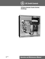
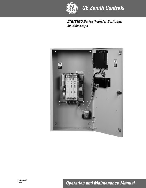
<strong>GE</strong> <strong>Zenith</strong> <strong>Controls</strong>ZTG/ZTGD Series Transfer Switches40-3000 Amps70R-1000D11/04Operation and Maintenance Manual
Authorized ServiceFor <strong>GE</strong> <strong>Zenith</strong> parts and service, call: (773) 299-6600Table of ContentsPageIntroduction . . . . . . . . . . . . . . . . . . . . . . . . . . . . . . .12Safety . . . . . . . . . . . . . . . . . . . . . . . . . . . . . . . . . . . . .13Equipment Inspection and Storage . . . . . . . . .13Final Equipment Inspection . . . . . . . . . . . . . . .13Installation . . . . . . . . . . . . . . . . . . . . . . . . . . . . . . . . .13Mounting . . . . . . . . . . . . . . . . . . . . . . . . . . . . . .13Power Connections . . . . . . . . . . . . . . . . . . . . . .14Engine Start Control Connections . . . . . . . .14-6Initial Energization . . . . . . . . . . . . . . . . . . . .16-7MX150 Microprocessor Controller . . . . . . . . . . . . .18Overview . . . . . . . . . . . . . . . . . . . . . . . . . . . . . . .18LCD & Keypad . . . . . . . . . . . . . . . . . . . . . . . . . .19User Setting for Voltage & Frequency . . . . . .110Standard Features, MSTDG Option Pkg. . .10-11Standard Features, MEXEG Option Pkg. . . . .12Optional Accessories . . . . . . . . . . . . . . . . . . . . .13How to Set the System Clock . . . . . . . . . . . . . .14CDT One Event Timer Exerciser . . . . . . . .14-15CDP Clock Exerciser . . . . . . . . . . . . . . . . . . . . .16User Setup - CFG Menu . . . . . . . . . . . . . . . . . .17User Setup - SET Menu . . . . . . . . . . . . . . . . . .18User Setup - System Info . . . . . . . . . . . . . . . . . .19Testing . . . . . . . . . . . . . . . . . . . . . . . . . . . . . . . . . . .120Standard Transition . . . . . . . . . . . . . . . . . . . . .120Delayed Transition . . . . . . . . . . . . . . . . . . . . . .20PageSequence of Operation . . . . . . . . . . . . . . . . . . . . . .21Standard Transition . . . . . . . . . . . . . . . . . . . . .121Delayed Transition . . . . . . . . . . . . . . . . . . . . . .21<strong>Controls</strong> Power Supply (CPS) . . . . . . . . . . . . . . . . .22Schematics, Standard & Delay . . . . . . . . . . . .123Troubleshooting & Diagnostics . . . . . . . . . . . . . . . .24Maintenance and Testing . . . . . . . . . . . . . . . . . . . . .25Inspection and Cleaning . . . . . . . . . . . . . . . . .25Servicing . . . . . . . . . . . . . . . . . . . . . . . . . . . . . .125Testing . . . . . . . . . . . . . . . . . . . . . . . . . . . . . . .125Power Panel & Replacement Parts . . . . . . . . . . . . .26Standard Transition . . . . . . . . . . . . . . . . . . . . . .2640-260 Amps . . . . . . . . . . . . . . . . . . . . . . . . . . .26400-600 Amps . . . . . . . . . . . . . . . . . . . . . . . . . .27800-1200 Amps . . . . . . . . . . . . . . . . . . . . . . . . .281600-3000 Amps . . . . . . . . . . . . . . . . . . . . . . . .29Delayed Transition . . . . . . . . . . . . . . . . . . . . . .3040-600 Amps . . . . . . . . . . . . . . . . . . . . . . . . . . .30800-1200 Amps . . . . . . . . . . . . . . . . . . . . . . . . .311600-3000 Amps . . . . . . . . . . . . . . . . . . . . . . . .32Introduction<strong>GE</strong> <strong>Zenith</strong> Transfer Switches are used to provide a continuous source of power for lighting and other critical loads by automaticallytransferring from source 1 power to source 2 power in the event that source 1 voltage falls below preset limits.Voltage sensing and system control is performed via a state-of-the-art microcontroller located on the cabinet door.It is designed to give highly accurate control of the transfer switch system.All <strong>GE</strong> <strong>Zenith</strong> transfer switches are designed for use on emergency or standby systems, and are rated for total system ormotor loads. Transfer switches are UL Listed under Standard 1008 and CSA Certified under Standard C22.2 No. 178 andIEC Listed under Standard 947.NOTES:A protective device such as a molded case circuit breaker or fuseddisconnect switch MUST be installed on both sources of incomingpower for circuit protection and as a disconnection device.All references made within this manual about the term “S1” or“Source 1” relate to a Normal Power Source. All references madeabout the term “S2” or “Source 2” relate to an Emergencyor Alternative Power Source.
Safety / InstallationDAN<strong>GE</strong>RHAZARDOUS VOLTA<strong>GE</strong>(Can Cause Severe Injury or Death)Turn OFF all power before installation, adjustment, or removal of transfer switch or any of its components.The safe operation of your switch is <strong>GE</strong> <strong>Zenith</strong>’s focus.The proper storage, installation, operation and maintenancewill help increase the life of the switch.Equipment Inspectionand StorageOnce you have received the transfer switch, inspectit for any damage. This includes damage to theenclosure, power panel, control panel and wiringharness. If any damage is found or suspected, file a claimas soon as possible with the carrier and notify the nearest<strong>GE</strong> <strong>Zenith</strong> representative.Before installation, if it is necessary, store the transferswitch in a clean dry place, protected from dirt andwater. Provide ample air circulation and heat, if necessary,to prevent condensation.-30°C to+75°C(-22°F to+167°F)CAUTIONDue to hazardous voltage and current, <strong>GE</strong> <strong>Zenith</strong> recommendsthat a <strong>GE</strong> <strong>Zenith</strong> Certified technician or aqualified electrician must perform theinstallation and maintenance of the switch.OperatingStorage TemperatureTemperature (Ambient): Humidity40-400 AMP(molded shell)-20°C to +65°C(-4°F to +149°F)40-4000 AMP(all other frameand panel types)-20°C to +60°C(-4°F to +140°F)5% to 95%(non-condensing)Final Equipment InspectionPrior to energizing the transfer switch:1. Remove any debris incurred, with a vacuum, dueto shipment or installation.WARNINGDo not use a blower since debris maybecome lodged in the electrical andmechanical components and cause damage.2. Verify that all cabled connections arecorrect and that phase rotation of both sourcesmatch.3. Check engine start connections.4. Verify the correct connection of allcontrol wires.5. Check settings of all timers and adjustas necessary.6. Adjust any optional accessories as required.7. Check the lug torque values of the powerconnections.NOTE: Lug torque values are specifiedin table 2 on pg.4.8. Make sure that all covers and barriers areinstalled and properly fastened.NOTE:Power panels ship from <strong>GE</strong> <strong>Zenith</strong>in Source 1 Position.Each <strong>GE</strong> <strong>Zenith</strong> transfer switch is factory wired andtested. A complete information package is furnishedwith each switch which includes:a. Sequence of operation.b. Description and operation ofall accessories supplied.c. Power panel connection diagramand schematic.d. Description and identification ofall customer field connections.Installation of <strong>GE</strong> <strong>Zenith</strong> transfer switches includes:a. Mounting the transfer switch cabinet.b. Connection of Source 1, Source 2,and Load cables or bus bars.c. Connection of external controlcircuits as required.MountingAdequate lifting means must be used to mount thetransfer switch into place. The recommended method formoving the transfer switch using the lifting eyes, wheresupplied, and a spreader bar is illustrated in Figure 1.Enough room should be allowed to open the cabinetdoors fully for inspection and servicing of the switch perNEC and local codes.CAUTIONBefore drilling conduit entry holes or anyaccessory mounting holes, cover and protectthe switch and control panel to prevent dirtand metal fragments from entering themechanical and electrical components.Failure to do so may result indamage and malfunction of the switch.■ <strong>GE</strong> <strong>Zenith</strong> <strong>Controls</strong>ZTG/ZTGD Operation and Maintenance Manual (70R-1000D)3 ■
Installation (cont’d)DAN<strong>GE</strong>RHAZARDOUS VOLTA<strong>GE</strong>(Can Cause Severe Injury or Death)Turn OFF all power before installation, adjustment, or removal of transfer switch or any of its components.Power Connections<strong>GE</strong> <strong>Zenith</strong> transfer switches are supplied with UL listedsolderless screw type terminals as standard for theSource 1, Source 2 and Load power connections.Table 1 lists the number and sizes of cable lugs suppliedas standard for each switch amp rating.H45°SPREADER BARConnect the Source 1, Source 2, and Load conductorsto the clearly marked terminals on the transfer switch.Remove surface oxides from cables by cleaning with awire brush. Verify that all connections are correct beforetightening the lugs. All cable lug connections must betightened to the proper torque values as shown inTable 2.LIFTING EYESNOTE:Do not run cables or wiring behindfront-connected transfer switches.CABINETFigure 1NOTE: When lifting the switch using a spreader bar,height H must be equal to half of distance D.DPower Connections: Screw Type Terminals for External Power ConnectionsSwitch Size Source 1, Source 2 & Load TerminalsNeutral Bar (When Required)(Amps) Cable Per Pole Range of Wire Sizes No. of Cables Range of Wire Sizes401 #8 to 3/0 AWG3 #14 to 1/0 AWG801 #8 to 3/0 AWG3 #14 to 1/0 AWG1001 #8 to 3/0 AWG3 #14 to 1/0 AWG1501 #8 to 3/0 AWG3 #6 AWG to 350 MCM200, 2251 #6 AWG to 250 MCM 3 #6 AWG to 350 MCM260 1 #6 AWG to 350 MCM 3 #6 AWG to 350 MCM4001 #4 AWG to 600 MCM 4 #4 AWG to 600 MCM6002 #2 AWG to 600 MCM 8 #4 AWG to 600 MCM800, 1000, 1200 4 #2 AWG to 600 MCM 12 #4 AWG to 600 MCM1600, 20002600, 30008 #2 AWG to 600 MCM 24 #4 AWG to 600 MCMTable 1Engine StartControl ConnectionsEngine-start control wires connect to control terminalsbeside the MX150. Engine start terminals are indicated bya schematic symbol (the symbol indicates the contactstate for a de-energized normal source). Figure 3 showsthe engine-start contacts.Make all other necessary control connections to the controlpanel terminal blocks per the schematics suppliedwith the ATS.NOTE:All control wires (18-12 AWG) must betorqued to 19 in/lbs.Table 2Tightening Torque for LugsSocket SizeTorqueAcross Flats Lb. - In.Lb. - Ft.1/8 4545/32 10083/16 120107/32 150121/4 200175/16 275233/8 375311/2 500429/16 60050■ 4ZTG/ZTGD Operation and Maintenance Manual (70R-1000D)<strong>GE</strong> <strong>Zenith</strong> <strong>Controls</strong> ■
Installation (cont’d)DAN<strong>GE</strong>RHAZARDOUS VOLTA<strong>GE</strong>(Can Cause Severe Injury or Death)Turn OFF all power before installation, adjustment, or removal of transfer switch or any of its components.41E5623P Relay(Engine Start)Contact rating is10 Ampere at 120VACor 28VDC Gold platedFigure 3Engine StartControl ConnectionsThe engine-start terminals are clearly identified by alabel on the microcontroller backplate. In the case ofmanual transfer switches, or in other applications notrequiring the microprocessor, clearly marked terminalblocks are provided in the upper left corner of the controlpanel for the engine start control wires.Terminals for field connections to the A3 Source 2auxiliary contacts and the A4 Source 1 auxiliary contactsare also provided. These terminals are clearly markedand appear on the side of the power panel. On 400amp metal frame units these terminals appear on thebracket above the operator handle.Initial EnergizationBefore proceeding, refer to the information packagesupplied with the ATS and read and understand theinformation on all accessories provided.1. Unlock the enclosure.2. Open the enclosure.3. Verify the correct system voltage.NOTE: The equipment rating nameplate onthe transfer switch lists the voltage.See Figure 4.4. Close Source 1 circuit. breaker.NOTE:The controller will illuminate Source 1Available LED if proper voltageis sensed.5. Verify the phase to phase voltages at the Normalline terminals.6. Close the Source 2 circuit breaker.7. Start the generator engine.NOTE: The controller will illuminate Source 2Available LED when preset voltageand frequency levels are reached.8. Verify the phase to phase voltages at Source 1line terminals.9. Verify that the phase rotation of Source 1is the same as the phase rotation ofSource 2.10. Shut down the generator engine.11. Place the starting control in the Automatic position.12. Complete the visual inspection of the transfer switch.13. Close the enclosure.14. Lock the enclosure.SERIAL NUMBER:RATING: VOLTS -AMPS -SYSTEM VOLTS:MODEL NUMBER:Figure 4<strong>GE</strong> <strong>Zenith</strong> <strong>Controls</strong>HZ -PHASE -CAUTIONSCertain accessories, per specificschematics, can inhibit automatic transfer.Engine Gen-Set could start whenengine control wires are attached.■ 6ZTG/ZTGD Operation and Maintenance Manual (70R-1000D)<strong>GE</strong> <strong>Zenith</strong> <strong>Controls</strong> ■
Installation (cont’d)Initial Energization (cont’d)After all options and accessories are checked and verified,follow these steps to set up the ATS. Refer to MX150display Figure 5. The annunciation LEDs illuminate toindicate (1) source availability, (2) ATS position, and (3)MX150 control function (timing).Figure 5 –S1 OK21:56MON 23 APR 2002MORE TESTLCD and keypadMX1501. Unlock the enclosure.2. Open the enclosure.3. Place the Disconnect Switch in the Inhibit.NOTE: This step is only performed if the“DS” Option was purchased.4. Close the external (up-stream) Source 1circuit breaker.NOTES: Source 1 Available and Source 1Position LED’s will illuminate.5. Close the External (up-stream) Source 2 linecircuit breaker.6. Start the engine generator in MANUAL mode.NOTE:When the voltage and frequencyreach preset values, the Source 2Available LED will illuminate.7. Verify the phase to phase voltages at Source 2line terminals.8. Verify that the phase rotation ofSource 2 is the same as the phaserotation of Source 1.9. Shut down the generator's engine.(Place in Automatic Mode.)NOTE:NOTE:Source 2 Available LEDwill turn off.The engine generator will continueto run for the duration of Source 2Stop Delay Timer.10. Place the disconnect switch to ENABLE.11. Complete the visual inspection of thetransfer switch.12. Close the enclosure.13. Lock the enclosure.WARNINGWhen performing a hi-pot ordielectric test on the power section,DISCONNECT the control panel plugs fromthe microprocessor to avoid potential damage.If Source 1 Available LED does notilluminate, verify that Source 1 Voltageis above the preset restore value.The Gen-Set will start and run whileSource 2 stop Delay Timer is timing.■ <strong>GE</strong> <strong>Zenith</strong> <strong>Controls</strong>ZTG/ZTGD Operation and Maintenance Manual (70R-1000D)7 ■
MX150 Microprocessor ControllerMX150 ControllerConsists of two major assemblies:I. The Microprocessor contains the following:A. MX150 Board - Customer Input and Output(I/O) for system interface. Located on the lefthand side of the back of the unit (see figure 6)1. I/O accessories that can be found here are:a. Engine start relay P outputb. Pre-Signal to transfer T3, W3 andUMD output (optional)c. Transfer Inhibit Q3 and Q7 input(optional)d. Remote test Q2 input (optional)e. Network interface ZNETinput/output (optional)I/O InterfaceEngine Start Relay PMX150BoardBattery StripandAccessCode LabelB. LCD and Keypad located on the exteriorof the door (see figure 7)1. User accessibility to the following:a. LED indication of sourceavailabilityb. LED indication of transferswitch positionc. LCD screen indicates:(1) timer count down (numeric)(2) event reporting (text)d. Keypad provides user interface to:[in conjunction with LCD screen](1) Setting sensors and timers(2) Configuring logic accessoriesCPSII.The <strong>Controls</strong> Power Supply (CPS)Contains transformers which drop line voltage tocontrol level for controller input and SCR inputs(see figure 6).Figure 6S1 OK21:56MON 23 APR 2002MORE TESTMX150Figure 7■ 8ZTG/ZTGD Operation and Maintenance Manual (70R-1000D)<strong>GE</strong> <strong>Zenith</strong> <strong>Controls</strong> ■
MX150 Microprocessor Controller (cont’d)LCD & KeypadThese options are accessible through the LCD andkeypad (see figure below). To become familiar with theoptions loaded into a particular unit, scrolling throughthe SET and CFG menu will show the descriptions ofthe options (see pages 17). These menus are the verysame menus that are used to access the setting and/orconfiguration of these options. The SET (setting) menuis primarily used to show or change, time and voltagesettings. The CFG menu is primarily used to turn anoption on or off. When scrolling through these menus,no changes can be made without entry of the access code.The factory set six-digit access code is located on a whitelabel on the back of the unit (see figure 9 pgs. 17-19).The MX150 has many logic options. Each controller isdownloaded with options at the time of manufacture.The collection of options that any one controller has isspecified at the time of order placement. The followingpages include all the options that can reside in thecontroller. Not all units include all options.Source 1 LED (Green)indicates Source 1 isacceptable for useSource 1 Position LED (Green)indicates Power Panel (ATS)is closed to Source 1 positionSource 2 PositionLED (Red) indicatesPower Panel (ATS)is closed toSource 2 positionSource 2 (Red)indicates Source 2is acceptable for useLCD ScreenCurrent Time,Day andDate of DisplayS1 OK * E *01: 50FRI 31 MAY 2003MORE CFG TEST SETExercise Event"Impending"SET MenuMORE Menu CFG Menu TEST MenuKeypadMX150#4 or the wordon the LCD above the key.The word above the keychanges depending on whichscreen is being displayed.#1 or the wordon the LCD above the key.The word above the keychanges depending on whichscreen is being displayed.#2 or the wordon the LCD above the key.The word above the keychanges depending on whichscreen is being displayed.#3 or the wordon the LCD above the key.The word above the keychanges depending on whichscreen is being displayed.Figure 8■ <strong>GE</strong> <strong>Zenith</strong> <strong>Controls</strong>ZTG/ZTGD Operation and Maintenance Manual (70R-1000D)9 ■
User Setting for Voltage & FrequencySource 1Voltage "Restore"Factory Default: 90%This adjustment determines the minimum acceptablevoltage required to transfer to Source 1.Adjust via the SET menu. Range is 85% to 100% in1% increments (see page 18).Once satisfied, the T timer will begin timingto transfer to Source 1.Voltage "Fail"Factory Default: 80%This adjustment determines the low voltage threshold.Adjust via the SET menu. Range is 75% to 98% in 1%increments (see page 18)."Fail" must be a minimum of 2 % below "Restore"setting. Once voltage falls below threshold, P timerbegins timing to signal Source 2 Generator to start.Source 2Voltage "Restore"Factory Default: 90%This adjustment determines the minimum acceptablevoltage required to transfer to Source 2.Adjust via the SET menu. Range is 85% to 100% in1% increments (see page 18).Once satisfied, the W timer will begin timingto transfer to Source 2.Voltage "Fail"Factory Default: 80%This adjustment determines the low voltage threshold.Adjust via the SET menu. Range is 75% to 98% in 1%increments (see page 18)."Fail" must be a minimum of 2 % below "Restore"setting. Once voltage falls below threshold, T timerwill be bypassed to expedite the transfer to Source 1.Frequency "Restore"Factory Default: 95%This adjustment determines the minimum acceptablefrequency required to transfer to Source 2.Adjust via the SET menu. Range is 90% to 100% in1% increments (see page 18).Once satisfied, the W timer will begin timingto transfer to Source 2.Frequency "Fail"Factory Default: 90%This adjustment determines the low frequency threshold.Adjust via the SET menu. Range is 88% to 98% in1% increments (see page 18)."Fail" must be a minimum of 2 % below "Restore" setting.Once satisfied, the W timer will begin timing to transferto Source 2.Standard Features, MSTDG Option Pkg.6Test Switch, MomentaryA3Auxiliary Contact: Closed when the switch is in Source 2position.A4Auxiliary Contact: Closed when the switch is in Source 1position.CalibrateWhile monitoring the actual Phase to Phase voltage levelsand Frequency with a calibrated test equipment, thePhase to Phase voltage sensing and Frequency can beadjusted accordingly. Calibration capabilities are availablefor Frequency and AB, BC, CA Phase to Phase voltage forboth Sources. Adjust via SET menu (see page 18)CDTLoad or NO-Load. One event exerciser with adjustableEngine exercise timer. Exercise duration can be setbetween 5 and 60 minutes in 1 minute increments. Canbe configured to run every 1, 7, 14, or 28 days. FactoryDefault is 20minutes. When exerciser is impending,(*E*) appears in the upper right hand corner of LCDscreen. See page 14-15 for instructions. Configured viaCFG (see page 17). Set via SET menu (see page 18).DSDisconnect Switch, Auto/Inhibit.Inhibits transfer in either direction when in inhibit.Allows automatic operation when in Auto.(800-4000 Amp units)DT (Delayed Transition Only)Time Delay from Neutral Switch position to Source 1position. Adjustable 0-10 minutes in 1 second increments.Standard setting is 5 seconds Adjust via SETmenu (see page 18)DW (Delayed Transition Only)Time Delay from Neutral Switch position to Source 2position. Adjustable 0-10 minutes in 1 second increments.Standard setting is 5 seconds.Adjust via SETmenu (see page 18)EEngine Start Contact■ 10ZTG/ZTGD Operation and Maintenance Manual (70R-1000D)<strong>GE</strong> <strong>Zenith</strong> <strong>Controls</strong> ■
Std. Features, MSTDG Option Pkg. (cont’d)EL/PEvent Log:Sequentially Numbered Logof 16 events that trackdate, time, reason and action takenSystem Data: Total Life Transfers (N2P)Days Powered UpTotal Transfers to S2Total S1 FailuresTime S1 available in HrsTime S2 available in Hrs. (N1P)K/PFrequency Indication for S1 and S2LLNP Center-off position LCD-IndicatorIndicating LED lights:L1 Indicates Switch in Source 2 position.L2 Indicates Switch in Source 1 position.L3 Indicates Source 1 available.L4 Indicates Source 2 available.P1Time Delay Source 2 Start. Adjustable 0-10 seconds.Standard setting is 3 seconds.Adjust via SET menu (see page 18)Q2Peak Shave / Remote Load Test: Input for Peak Shaveor Remote Load Test. Includes automatic return toSource 1 if Source 2 fails and Source 1 present.R2EUnder voltage sensing of Source 2 for single-phase.(R17 replaces R2E for Utility to Utility switches)R50In Phase Monitor this feature restricts Live to LiveSource Transfers to occur unless both Sources are within7 electrical degrees or less of each other. (live Source tolive Source transfers usually occur during transfer backto Source 1 or during Testing). R50 does not changethe operation of the Automatic Transfer Switch in apower failure mode. After all timer functions haveelapsed, the CHECKING FOR SOURCE SYNCHRO-NISM will be displayed as well as the direction oftransfer (S1-S2 for example denotes transfer fromSource 1 to Source2). When synchronism is accomplished,transfer will take place.Notes: - If S2 Frequency is less than S1 Frequency,display will show a series of (- - - - -…..) symbols.- If S2 Frequency is greater than S1 Frequency,display will show a series of (+++++…..) symbols.- Each (-) or (+) symbol represents 10 electricaldegrees out of phase. A maximum of 18 symbols(180 electrical degrees) can be monitored.- The number of (-) or (+) symbols decreaseas the two sources approach synchronismand increase as the two sources drift outof synchronism.- If S1 and S2 Frequencies are identical, thedisplay will show a series of alternatingsymbols (++++…) - - - - which also indicate theapproximate out of phase degreesIn the event that the Sources do not come within 7electrical degrees of each other within 60 seconds, theunit will display the message: SYNCH CHECKING andwill allow the user to BYPASS. If the BYPASS button ispressed, the unit will display the message: WARNINGMAY CAUSE DAMA<strong>GE</strong> TO THE LOAD. Pressing XFRwill actually bypass the R50. Since R50 is a passive device,the length of time it takes to reach Synchronism is dependenton the frequency difference between the twoSources. Source 1 is usually a Utility and the frequencyis not within the control of the consumer. Source 2needs to be adjusted to create an adequate differencein order for the transfer to happen a timely fashion.Note: For optimum performance, Source 2Generator should be adjusted a Maximum of2 Hertz above or below the Utility frequency,minimum of 0.1 Hertz. (58 to 59.9) or(60.1 to 62) Hertz. Adjustment of Generatorto 60Hertz could cause lengthy transfer delay.R50 Feature can be turned ON or OFF via CFG Menu(see page 17). Factory Default if OFF.S13Transfer Commit. Configured via CFG menu.(see page 17) When this Feature is set to OFF:The transfer Switch is not committed to transfer unlessthe outage duration is longer than the timers thatprecede the transfer to Source 2 position. This assumesthat the outage will be an isolated event. When thisFeature is set to ON: The transfer Switch is committedto transfer to Source 2 position once the W timer hasbegun timing, even if Source 1 power returns beforethe transfer to Source 2. This is to ensure that thetransfer takes place, because one outage may befollowed by another.TTime Delay (S1) Source 1 Stable Timer. To delay transferto Source 1 (immediate retransfer on Source 2 failure).Adjustable 0-60 minutes in 1 second increments.Standard setting is 30 minutes. Adjust via SET menu(see page 18)U(S2) Source 2 Stop Delay Timer. Allows Engine to rununloaded after switch retransfer to Source 1. Adjustable0-60 minutes in 1 second increments. Standard setting is5 minutes. Adjust via SET menu (see page 18)WTime Delay (S2) Source 2 Stable Timer. To delay transferto Source 2. Adjustable 0-5 minutes in 1 secondincrements. Standard setting is 1 second. Adjust via SETmenu (see page 18)YENBypass Timers Key utilizing Keypad. When applicable,the system prompts the user to press a button to bypass(T) or (W) Timers should the user so desires.■ <strong>GE</strong> <strong>Zenith</strong> <strong>Controls</strong>ZTG/ZTGD Operation and Maintenance Manual (70R-1000D)11 ■
Standard Features, MEXEG Option Pkg.In addition to the features listed under theMSTDG Option Package, this enhanced packageincludes the following features:A3Additional Auxiliary contact: closed when switch is inSource 2 position.A4Additional Auxiliary contact: Closed when the transferswitch is in Source 1 position.CDP (replaces CDT)Clock Exerciser Load/ No Load: Allows the Generatorto start and run unloaded or to simulate a powerfailure, start Generator and run under load.Can be configured by end user for 1, 7, 14,28, 365 day cycle.VIVoltage Imbalance (Three Phase)For a three phase source, this feature monitors phasevoltage ratios based on a selected range within aselected time window. Should any phase fall below theselected lower window limit or exceed the selectedhigher window limit within the selected time frame,the controller initiates transfer to the other source.Range: 5% to 20% of Nominal voltage,10 to 30 seconds window, user adjustable.Resolution: 1% IncrementsMinimum Differential: 2% between “Fail”and “Restore” settings.Factory default: 10% “Fail”, 8% “Restore, 30 Seconds.See CFG Menu page 17 to configure ON or OFF.See SET Menu page 18 to set Percentage and timewindows■ 12ZTG/ZTGD Operation and Maintenance Manual (70R-1000D)<strong>GE</strong> <strong>Zenith</strong> <strong>Controls</strong> ■
Optional Accessories6ATest Switch, Maintained / Momentary6APTest Switch, Maintained / Momentary, utilizing KeypadA1Auxiliary Contact, operates on Source 1 line failure.A1EAuxiliary Contact, operates on Source 2 line failure.A3Auxiliary Contacts: Closed when the transfer switchis in Source 2 position.A4Auxiliary Contacts: Closed when the transfer switchis in Source 1 position.A62Sequential Universal Motor Load Disconnect Circuit.Normally closed Auxiliary contacts for Motor Loads.Open 0-60 seconds prior to transfer, after transfer, orboth in either direction then re-close in timed sequenceafter transfer. Factory default: 20 secondsCTAPAlarm Panel on transfer to Source 2 with Silence button.DSDisconnect Switch, Auto/Inhibit.Inhibits transfer in either direction when in inhibit.Allows automatic operation when in Auto.(40-600 Amp units)HTHeater and Thermostat.M82Digital Meter w/Display of Amps, Watts, Volts,Frequency, KVA, KVAR, PF, etc.M83ADigital Meter w/Diplay of Amps, Watts, Volts,Frequency, KVA, KVAR, PF, etc. Plus THD capabilityw/Modbus.T3/W3Elevator Pre-Signal Auxiliary Contacts: Open 0-60seconds prior to transfer to either direction,re-closes after transfer. Factory default: 20 secondsUMDUniversal Motor Load Disconnect Circuit: AuxiliaryContact opens 0-5 minutes prior to transfer in eitherdirection, re-closes after transfer. Can be configuredby end user for Pre-transfer, Post-transfer, or both.Factory default: 15 secondsVIVoltage Imbalance (Three Phase)For a three phase source, this feature monitors phasevoltage ratios based on a selected range within aselected time window. Should any phase fall below theselected lower window limit or exceed the selectedhigher window limit within the selected time frame,the controller initiates transfer to the other source.Range: 5% to 20% of Nominal voltage,10 to 30 seconds window, user adjustable.Resolution: 1% IncrementsMinimum Differential: 2% between “Fail”and “Restore” settings.Factory default: 10% “Fail”, 8% “Restore, 30 Seconds.See CFG Menu page 17 to configure ON or OFF.See SET Menu page 18 to set Percentage and timewindowsZNETNetwork Communications Interface CardManualManual Transfer Switch transfers in either directionby depressing designated pushbuttons.M80Digital Power Meter with Display: Amps, Volts, andFrequency.■ <strong>GE</strong> <strong>Zenith</strong> <strong>Controls</strong>ZTG/ZTGD Operation and Maintenance Manual (70R-1000D)13 ■
How to Set the System ClockHow to Set the System ClockSet System Clock, time and date· If the clock is not set, the display will showSET SYSTEM CLOCK on the second lineof the S1 OK screen.· The S1 OK screen will show time (hours andminutes) on the second line if the system clockhas been set. (Date on third line)Setting the System Clock(Start from S1 OK screen)1. Remove battery protective white plastic stripnear P relay. *2. Press MORE then press SET.3. Press MORE and scroll to SET SYSTEM CLOCKusing the MORE key.4. Press SEL.5. ENTER ACCESS CODE located on the white labelon the back of the controller.6. Press SEL.7. Use the up and down keys to change the hour value.8. Press SAVE (this will enter this value and movecursor to minutes).9. Use the up and down keys to change the minutes.10. Press SAVE (this will enter this value and movecursor to month).11. Use the up and down key up to change the month.12. Press SAVE (This will enter this value and completethe clock setting).13. Use the up and down keys to change the date.14. Press SAVE (this will enter this value and movecursor to year).15. Use the up and down keys to change year.16. Press SAVE (this will enter this value andcompete the clock setting).17. To edit settings, press SEL and repeat steps 6-16.18. If the setting is satisfactory, press MORE(unit then returns to the SET menu thenpress BACK, then ESC.)* Replacement battery part #K-4100Battery will last 5 years and provides power to retain clockfunction only (Controller functions without battery).CDT One Event Timer ExerciserLoad / No-LoadOne event Exerciser with adjustable Timer. Exerciseduration can be set between 5 and 60 minutes in1 minute increments. Can be configured to run every1,7,14, or 28 days. Factory default is 20 minutes.How to CONFIGURE (CFG) and Set (SET)the Timer Exerciser1. Beginning from the S1 OK screen,press MORE then CFG.2. Press MORE to scroll to CONFIG TIMEREXERCISER screen.3. The third line of the CONFG TIMER EXERCISERwill show either DAILY, WEEKLY, 14 DAY, 28 DAY,or OFF.4. If the third line of the CONFG TIMER EXERCISERshows DAILY, WEEKLY, 14 DAY, or 28 DAY asdesired, then proceed to step 10.5. If the third line of the CONFG TIMER EXERCISERshows OFF or if another timer selection is desired,continue.6. Press SEL.7. Enter ACCESS code located on white labelon the back of the controller.8. Press UP or DOWN to select DAILY, WEEKLY,14 DAY, or 28 DAY as desired.9. Press SAVE.10. Press MORE to scroll to CONFG TIMEREXERCISER (XFR) or (NO XFR).11. Press Up or Down to select XFR (Load Transfer)or NO XFR (No Load Transfer).12. Press SAVE.13. Press MORE repeatedly to BACK then S1 OK screen.Set (SET) the Exerciser:14. Beginning from the S1 OK screen,press MORE then SET.15. Press MORE repeatedly untilEXER S2 RUN TIME screen.16. Press SEL17. Enter ACCESS code located on white labelon the back of the controller.18. Press SEL19. Cursor is indicated as a line under character tobe changed. Change values with up and down keys.20. Press SAVE when complete.21. Press MORE repeatedly until SET USER SETUPthen press BACK then ESC to the S1 OK screen.■ 14ZTG/ZTGD Operation and Maintenance Manual (70R-1000D)<strong>GE</strong> <strong>Zenith</strong> <strong>Controls</strong> ■
CDT One Event Timer Exerciser (cont’d)How to Initiate CDT Exerciser and to start anexercise cycle every 1, 7, 14, or 28 daysFrom S1 screen1) Press TEST2) Press MORE3) Press START TEST TIMER (to initiate Test).• If the CDT Exerciser is Factory configured for aLoad Exerciser, the Controller will immediately starta load exercise. The controller will start thegenerator, transfer the load to Source 2 and remainin Source 2 for the duration set for EXER S2 RUNTIME in the SET menu. The controller willretransfer the load back to Source 1 after the S1stable timer has timed out and run the generatorunloaded for the duration of the S2 stop delay timer(Engine Cool Down Timer).• If the CDT Exerciser is Factory configured for aNo-Load Exerciser, the Controller will immediatelystart a No-load exercise. The controller will start thegenerator and run it unloaded for the duration ofthe S2 stop delay timer (Engine Cool Down Timer).Exercise will be repeated at the same time as initiatedon every 1, 7, 14, or 28 days according to the selectionmade in the Configure CFG menu.How to Bypass (Cancel) an exercise duringan exercise cycle1) Press BPASS2) Allow the controller to complete the Enginecool down cycleIf the CDT Exerciser is Factory configured for aNo-Load Exerciser Or allow the controller to completeretransfer to Source 1 If the CDT Exerciser is Factoryconfigured for a Load ExerciserHow to Bypass the next exercise event and Keepthe rest of scheduled events unchanged1) Press Test2) Press MORE3) Press BYPASS EXERTo re-institute the next exercise event back,press CANCL BPASSHow to initiate a new exercise start time1) Press TEST2) Press MORE3) Press EXER CANCL4) Press START TIMER TESTHow to check the next exercise event1) From S1 OK screen, press MORE three times.2) The unit will display the PLANT EXERCISER NEXTevent in DAYS, HOURS, and MINUTES3) Press ESC to S1 OK Screen.Notes:- *E* appears in the upper right hand cornerof LCD screen when exercise is impending.- For Load Exerciser, actual exercise period(ATS in S2 position)= CDT (Exerciser)timing period +T (S1 stable Timer) timing period.■ <strong>GE</strong> <strong>Zenith</strong> <strong>Controls</strong>ZTG/ZTGD Operation and Maintenance Manual (70R-1000D)15 ■
CDP Clock ExerciserLoad / No-Load Clock ExerciserAllows the Generator to start and run unloaded or tosimulate a power failure, start Generator and run underload. Can be configured by the end user for 1, 7, 14, 28,or 365 day cycles.• A total of 7 independent No Load exercise periods(up to 10 hours each) can be programmed for eachof the daily, weekly, 14-day, and 28-day exercisers.• A total of 12 independent No Load exercise periods(up to 10 hours) can be programmed for the365-day Exerciser.How to Configure (CFG) the Exerciser1. Beginning from the S1 OK screen, press MOREthen CFG.2. Press MORE to scroll to CONFIG CLOCKEXERCISER screen.3. The third line of the CONFG CLOCK EXERCISERwill show either DAILY, WEEKLY, 14 DAY, 28 DAY,365 DAY or OFF.4. If the third line of the CONFG CLOCK EXERCISERshows DAILY, WEEKLY, 14 DAY, 28 DAY, or 365 DAYas desired, press MORE repeatedly to BACK.Press ESC then proceed to the SET menu toset the EXERCISER.5. If the third line of the CONFG CLOCK EXERCISERshows OFF, continue.6. Press SEL.7. Enter ACCESS code located on white label onthe back of the controller.8. Press UP or DOWN to select DAILY, WEEKLY,14 DAY, 28 DAY, or 365 DAY as desired.9. Press SAVE.10. Press MORE repeatedly to BACK then ESCto S1 OK screen.How to set (SET) the DAILY Exerciser1. Beginning from the S1 OK screen, press MOREthen SET.2. Press MORE repeatedly until SET EXERCISERscreen.3. Press SEL.4. Enter ACCESS code located on white labelon the back of the controller.5. Press SEL6. Cursor is indicated as a line under character tobe changed. Change values with up and down keys.Press SAVE after each entry to save value and tomove to the next value to be changed.7. Press BACK when complete.8. Press MORE repeatedly until SET USER SETUP.Press BACK then ESC to the S1 OK screen.How to Bypass (Cancel) an exercise duringan exercise cycle1) Press BPASS2) Allow the controller to complete the Enginecool down cycle.If the CD Exerciser is configured or Set for a No-LoadExercise. Or allow the controller to complete retransferto Source 1. If the CD Exerciser is configured for aLoad ExerciserHow to Bypass the next exercise event and Keepthe rest of scheduled events unchanged1) Press TEST2) Press MORE3) Press BYPASS EXERTo re-institute the next exercise event back,press CANCL BPASSHow to check the next exercise event1) From S1 OK screen, press MORE three times.2) The unit will display the PLANT EXERCISER NEXTevent in DAYS, HOURS, and MINUTES3) Press ESC to S1 OK Screen.Notes:• In the S1 OK screen, an (*E*) appears in the upperright hand corner of LCD screen when exerciseis impending.• For Load Exerciser, actual exercise period(ATS in S2 position)= CDT (Exerciser)timing period +T (S1 Stable Timer) timing period.• A value greater than zero must be entered in theExerciser duration field to be accepted as a validexercise period.• The Exercise cycle will be repeated on a regularbasis as programmed and initiated in the SET menudepending on what Exerciser was configured(selected) in the CFG menu.Indicates # ofExercise PeriodsIndicates type of ExerciserDAILY, WEEKLY, 14-DAY,28-DAY or 365-DAYIndicates Exerciser start:Time for DAILY ExerciserTime & Day for WEEKLY ExerciserTime, Date & Month for 14-DAY,28-DAY and 365-DAY Exerciser(24 Hour System)#1 SET NLEXERCISER00:00BACK ^ v SAVETo previous fieldor to exit screen.CursorUp and DownUse to change values.To save value and tomove cursor to nextfield to be changed.Load No-Load (CDP)Exercise IndicatorExercise duration for thisevent in hours and minutesup to 10 hours per event■ 16ZTG/ZTGD Operation and Maintenance Manual (70R-1000D)<strong>GE</strong> <strong>Zenith</strong> <strong>Controls</strong> ■
MX150 User Setup - CFG MenuS1 OK01: 50FRI 31 MAY 2003MORETESTTurn options ON or OFF viakeypad through the CFG menuEnter six digit access code(The factory assigned six-digit access codeis located on the back of the controller)1 VAB = ___ 2 VAB = ___VBC = ___VCA = ___MORE CFG SET ESCMORECONFIGUSER SETUPBACKJ2*415263Engine Start Relay (De-Energized)Network Communications(Option)123456789101112PROG 1PROG 2NIA OUTELEV. PRE. OUTALARM OUTGRD (InputSink)MOTOR DISC. OUTA2(-)WARNING1 Controller Inputs must be relay Isolated.CustomerInputVoltageA1(+) RELAY 14 11 122 Controller Outputs have "Limited" Source Capacity.Use only <strong>GE</strong> <strong>Zenith</strong>-specified Output Modules.11 141221 24 22OutputContactsR1N.OCOMJ2-3ToJ2/J4InputsN.CA1(+)A2(-)131415INHIB.>S1INHIB.>S216111412212422R1 OutputR1 OutputJ4*1234567891011121314*+12v (Output Source)LN OUTL4 OUTL3 OUTL2 OUTL1 OUTYN INYE INTSNL INQ2/TSL INS12 INLithium BatteryUser Access CodePRODUCT INFORMATIONExerciser BatteryReplacement-K-4100 (BR2032)Service Life-10 YearsDuring normal operationDefault-121212www.geindustrial.com24-Hour Service (773)299-6600Contact Rating: 10A @ 250 VAC or 30 VDCMX150Figure 9Optional Accessories■ <strong>GE</strong> <strong>Zenith</strong> <strong>Controls</strong>ZTG/ZTGD Operation and Maintenance Manual (70R-1000D)17 ■
MX150 User Setup - SET MenuS1 OK01: 50FRI 31 MAY 2003MORETEST1 VAB = ___ 2 VAB = ___VBC = ___VCA = ___MORE CFG SET ESCChange adjustable valuesthrough the SET menu.Enter six digit access code(The factory assigned six-digit access codeis located on the back of the controller)MORESETUSER SETUPBACKJ2*415263Engine Start Relay (De-Energized)Network Communications(Option)1234PROG 1PROG 2GRD (InputSink)WARNING1 Controller Inputs must be relay Isolated.A2 A1(+) RELAY 14 11 12(-)COMJ2-3CustomerInputN.O N.CVoltageToJ2/J4Inputs56789101112NIA OUTELEV. PRE. OUTALARM OUTMOTOR DISC. OUT2 Controller Outputs have "Limited" Source Capacity.Use only <strong>GE</strong> <strong>Zenith</strong>-specified Output Modules.11 141221 24 22OutputContactsR1A1(+)A2(-)131415INHIB.>S1INHIB.>S216111412212422R1 OutputR1 OutputJ4*1234567891011121314*+12v (Output Source)LN OUTL4 OUTL3 OUTL2 OUTL1 OUTYN INYE INTSNL INQ2/TSL INS12 INLithium BatteryUser Access CodePRODUCT INFORMATIONExerciser BatteryReplacement-K-4100 (BR2032)Service Life-10 YearsDuring normal operationDefault-121212www.geindustrial.com24-Hour Service (773)299-6600Contact Rating: 10A @ 250 VAC or 30 VDCMX150Figure 9Optional Accessories■ 18ZTG/ZTGD Operation and Maintenance Manual (70R-1000D)<strong>GE</strong> <strong>Zenith</strong> <strong>Controls</strong> ■
MX150 User Setup - System InfoS1 OK01: 50FRI 31 MAY 2003MORETESTView System DataEnter six digit access code(The factory assigned six-digit access codeis located on the back of the controller)J2*415263Engine Start Relay (De-Energized)Network Communications(Option)1234PROG 1PROG 2GRD (InputSink)WARNING1 Controller Inputs must be relay Isolated.A2 A1(+) RELAY 14 11 12(-)COMJ2-3CustomerInputN.O N.CVoltageToJ2/J4Inputs56789101112NIA OUTELEV. PRE. OUTALARM OUTMOTOR DISC. OUT2 Controller Outputs have "Limited" Source Capacity.Use only <strong>GE</strong> <strong>Zenith</strong>-specified Output Modules.11 141221 24 22OutputContactsR1A1(+)A2(-)131415INHIB.>S1INHIB.>S216111412212422R1 OutputR1 OutputJ4*1234567891011121314*+12v (Output Source)LN OUTL4 OUTL3 OUTL2 OUTL1 OUTYN INYE INTSNL INQ2/TSL INS12 INLithium BatteryUser Access CodePRODUCT INFORMATIONExerciser BatteryReplacement-K-4100 (BR2032)Service Life-10 YearsDuring normal operationDefault-121212www.geindustrial.com24-Hour Service (773)299-6600Contact Rating: 10A @ 250 VAC or 30 VDCMX150Figure 9■ <strong>GE</strong> <strong>Zenith</strong> <strong>Controls</strong>ZTG/ZTGD Operation and Maintenance Manual (70R-1000D)19 ■
TestingNOTICEA periodic test of the transfer switch under load conditions is recommended to insure proper operation.(See National Electric Code articles 700 and 701)ATS TestingStart generator and verify proper voltage, frequency and phasesequence (match to Source 1). Shut down gen set and place inAuto. Complete the visual inspection of the transfer switch, andclose the cabinet door.Initiate the test by pressing the TEST button on the LCDkeypad. The controller will then prompt for your access code.After entering the code, three test options will appear—XFR LOAD, FAST TEST and NO XFR (See Figure 10).SYSTEM TESTFAST XFR NOMORE TEST LOAD XFRMX150Figure 10• XFR LOAD test starts the generator and using thecurrent timer settings, transfers the load to Source 2.• FAST TEST test presets timer values to a maximum30 seconds during the test. After completion ofthe test, all timers are reset to their originalvalues. (T3, W3, DT and DW remain)• NO XFR test starts the generator but does nottransfer the load to the Source 2.Press and hold the desired test option button until the switchtransfers to Source 2 (load test) or until the generator has beenrun for the desired amount of time (no load test). Releasing thetest button before W timer timeout will abort the test (Exception:when the transfer commit option, is configured “ON”).To test lamps, press TEST then scroll through MORE, thenpress LAMP TEST. To cancel LAMP TEST press MORE.Standard TransitionWhen the test is initiated, the controller initiates the Time DelaySource 2 Start Timer (Engine Start Timer "P") cycle. A manualCANCEL button is provided to cancel the test if desired. Uponcompletion of the (P) time delay, an Engine start Signal is sent toSource 2. When Source 2 voltage and frequency reach the preset"Restore" Values, the time delay to Source 2 Timer (W) begins itstiming cycle to ensure voltage and frequency stabilization beforetransfer. A manual pushbutton BYPASS is provided to bypass the"W" time delay if desired. After the (W) time delay, the MX controllerinitiates a transfer signal through the SCR-E to operate themain transfer operator. The load is now transferred to Source 2line. The transfer switch is mechanically locked. SN limit switchawaits the next operation to Source 1.Restoration of Source 1 Power:Deactivating the test switch initiates re-transfer to Source 1 sequence.The delay to Source 1 Timer (T) begins its timing cycle to ensurevoltage and frequency stabilization before retransfer. A manual pushbuttonBYPASS is provided to bypass the "T" time delay if desired.After the (T) time delay, the MX controller initiates a transfer signalthrough the SCR-N to operate the main transfer operator. The loadis now transferred to Source 1 line. The transfer switch is mechanicallylocked. SE limit switch awaits the next operation to Source 2.Immediately after re-transfer, the S2 Stop Delay Timer (Delayto Engine Stop "U") begins its cycle to allow Source 2 Engineto run unloaded. A manual pushbutton BYPASS is provided tobypass the "U" time delay if desired. Upon completion of the(U) timing cycle, the controller sends an Engine stop signal.Delayed TransitionSource 1 Power Failure:When the test is initiated, the controller initiates the TimeDelay Source 2 Start (Engine Start Timer "P") cycle. A manualCANCEL button is provided to cancel the test if desired Uponcompletion of the (P) time delay, an Engine start Signal is sentto Source 2. When Source 2 voltage and frequency reach thepreset "Restore" values, the time delay to open Source 1 timer(W) begins its timing cycle to ensure voltage and frequency stabilizationbefore re-transfer. A manual pushbutton BYPASS isprovided to bypass the "W" time delay if desired. After the (W)time delay, the MX controller initiates a transfer signal throughthe SCR-NO to operate the main transfer operator. The load isnow transferred to the Open position. The time delay to Source 2timer (DW) begins its timing cycle. After the (DW) time delay,the MX controller initiates a transfer signal through the SCR-Eto operate the main transfer operator. The load is now transferredto Source 2 line. The transfer switch is mechanicallylocked. SN limit switch awaits the next operation to Source 1.Restoration of Source 1 Power:Deactivating the test switch initiates re-transfer to Source 1sequence.The delay to open Source 2 Timer (T) begins its timing cycle toensure voltage and frequency stabilization before retransfer. Amanual pushbutton BYPASS is provided to bypass the "T" timedelay if desired. After the (T) time delay, the MX controller initiatesa transfer signal through the SCR-EO to operate the main transferoperator. The load is now transferred to the Open position. Thetime delay to Source 1 timer (DT) begins its timing cycle. After the(DT) time delay, the MX controller initiates a transfer signal throughthe SCR-N to operate the main transfer operator. The load is nowtransferred to Source 1 line. The transfer switch is mechanicallylocked. SE limit switch awaits the next operation to Source 2.Immediately after re-transfer, the S2 Stop Delay Timer (Delayto Engine Stop "U") begins its cycle to allow Source 2 Engineto run unloaded. A manual pushbutton BYPASS is provided tobypass the "U" time delay if desired. Upon completion of the(U) timing cycle, the controller sends an Engine stop signal.■ 20ZTG/ZTGD Operation and Maintenance Manual (70R-1000D)<strong>GE</strong> <strong>Zenith</strong> <strong>Controls</strong> ■
Sequence of OperationStandard TransitionSource 1 Power Failure:When Source 1 voltage or frequency has fallen belowthe preset "Fail" values, the controller initiates the TimeDelay Source 2 Start Timer (Engine Start Timer "P")cycle. Upon completion of the (P) time delay, anEngine start Signal is sent to Source 2. When Source 2voltage and frequency reach the preset "Restore" Values,the time delay to Source 2 Timer (W) begins its timingcycle to ensure voltage and frequency stabilizationbefore transfer. A manual pushbutton BYPASS is providedto bypass the "W" time delay if desired. After the (W)time delay, the MX controller initiates a transfer signalthrough the SCR-E to operate the main transfer operator.The load is now transferred to Source 2 line. The transferswitch is mechanically locked. SN limit switch awaits thenext operation to Source 1.Restoration of Source 1 Power:When Source 1 power reach the preset "Restore" values,the controller initiates re-transfer to Source 1sequence.The delay to Source 1 Timer (T) begins its timing cycleto ensure voltage and frequency stabilization beforeretransfer. A manual pushbutton BYPASS is provided tobypass the "T" time delay if desired. After the (T) timedelay, the MX controller initiates a transfer signalthrough the SCR-N to operate the main transfer operator.The load is now transferred to Source 1 line. Thetransfer switch is mechanically locked. SE limit switchawaits the next operation to Source 2.Immediately after re-transfer, the S2 Stop Delay Timer(Delay to Engine Stop "U") begins its cycle to allowSource 2 Engine to run unloaded. A manual pushbuttonBYPASS is provided to bypass the "U" time delay ifdesired. Upon completion of the (U) timing cycle, thecontroller sends an Engine stop signal.Delayed TransitionDelay Source 2 Start (Engine Start Timer "P") cycle. Uponcompletion of the (P) time delay, an Engine start Signalis sent to Source 2. When Source 2 voltage and frequencyreach the preset "Restore" values, the time delay to openSource 1 timer (W) begins its timing cycle to ensurevoltage and frequency stabilization before re-transfer. Amanual pushbutton BYPASS is provided to bypass the"W" time delay if desired. After the (W) time delay, theMX controller initiates a transfer signal through theSCR-NO to operate the main transfer operator. Theload is now transferred to the Open position. The timedelay to Source 2 timer (DW) begins its timing cycle.After the (DW) time delay, the MX controller initiates atransfer signal through the SCR-E to operate the maintransfer operator. The load is now transferred to Source2 line. The transfer switch is mechanically locked. SNlimit switch awaits the next operation to Source 1.Restoration of Source 1 Power:When Source 1 power reach the preset "Restore" values,the controller initiates re-transfer to Source 1 sequence.The delay to open Source 2 Timer (T) begins its timingcycle to ensure voltage and frequency stabilization beforeretransfer. A manual pushbutton BYPASS is provided tobypass the "T" time delay if desired. After the (T) timedelay, the MX controller initiates a transfer signal throughthe SCR-EO to operate the main transfer operator. Theload is now transferred to the Open position. The timedelay to Source 1 timer (DT) begins its timing cycle.After the (DT) time delay, the MX controller initiates atransfer signal throught the SCR-N to operate the maintransfer operator. The load is now transferred to Source1 line. The transfer switch is mechanically locked. SElimit switch awaits the next operation to Source 2.Immediately after re-transfer, the S2 Stop Delay Timer(Delay to Engine Stop "U") begins its cycle to allowSource 2 Engine to run unloaded. A manual pushbuttonBYPASS is provided to bypass the "U" time delay ifdesired. Upon completion of the (U) timing cycle, thecontroller sends an Engine stop signal.Source 1 Power Failure:When Source 1 voltage or frequency has fallen below thepreset "Fail" values, the controller initiates the TimeTable 3Timer Designations as they appear in the SET menuATS Type P W DW T DT UStandard Time Delay Time Delay Time Delay S2 StopS2 Start S2 Stable S1 Stable DelayDelay Time Delay Time Delay ATS Open Time Delay ATS Open S2 StopS2 Start S2 Stable Time to S2 S1 Stable Time to S1 DelaySource 1 Transfer to Source 2 Source 1 Transfer to Source 1 EngineFails Returns Cooldown■ <strong>GE</strong> <strong>Zenith</strong> <strong>Controls</strong>ZTG/ZTGD Operation and Maintenance Manual (70R-1000D)21 ■
<strong>Controls</strong> Power Supply (CPS)Standard and Delay TransitionEach MX150 microprocessor based ATS controllerrequires a <strong>Controls</strong> Power Supply (CPS) to apply linevoltage to the ATS operator via SCRs. Also required ispower for the MX150 printed circuit board and anapplication of sensing voltage proportional to line voltage.This is accomplished by the <strong>Controls</strong> Power Supply (CPS).This method of switching operator voltage and applyingpower and sensing voltage to the printed circuit boardisolates the MX150 from the line voltage, further protectingthe controller from harmful line transients.Primary CPS CPSVoltage Assembly Boardat 50/60 Hz Part No. No.120V 50P-1224 50P-1200208-220V 50P-1225 50P-1201230-240V 50P-1226 50P-1202277V 50P-1227 50P-1203380-400V 50P-1228 50P-1204416-440V 50P-1229 50P-1205460-480V 50P-1230 50P-1206575-600V 50P-1231 50P-1207■ 22ZTG/ZTGD Operation and Maintenance Manual (70R-1000D)<strong>GE</strong> <strong>Zenith</strong> <strong>Controls</strong> ■
<strong>Controls</strong> Power Supply (CPS) (cont’d)Standard Transition CPS Schematic20 21 2230 3132XN1 - SOURCE 1 CONTROL TRANSFORMERXN2 -SOURCE 1 3 PHASE SENSINGTRANSFORMERXN1XN2XE1XE2XE1 - SOURCE 2 CONTROL TRANSFORMER24V 10V 11V 10V24V 10V 11VXE2 - SOURCE 2 3 PHASE SENSING TRANSFORMER800902JCC.V.SCR-N801JC804803805806804807900JCC.V.SCR-E902JC904903905906904907900800907808908GND901801902903(18)SOURCE 2 24V OUTPUTSOURCE 1 24V OUTPUT3 PHASE SOURCE 2(BLANK)(BLANK)GROUNDC.V. SCR-E CONTROL VOLTA<strong>GE</strong> (SOURCE 2)C.V. SCR-N CONTROL VOLTA<strong>GE</strong> (SOURCE 1)COMMON904SINGLE PHASE SOURCE 2 SENSING8038048073-PHASE SOURCE 1 SENSING806805SOURCE 1 CONTROL POWER906905(1)SOURCE 2 CONTROL POWERJ5Delayed Transition CPS Schematic20 21 223031 32XN1XN224V 10V 11V 10VXE1XE224V 10V 11V 10VXN1 - SOURCE 1 CONTROL TRANSFORMERXN2 - SOURCE 1 3 PHASE SENSINGTRANSFORMERXE1 - SOURCE 2 CONTROL TRANSFORMERXE2 - SOURCE 2 3 PHASE SENSINGTRANSFORMER800902804803805806804807900902904903905906904907900800907(18) SOURCE 2 24V OUTPUTSOURCE 1 24V OUTPUT3-PHASE SOURCE 2 SENSINGJCC.V.SCR-EOJC808JCJCC.V.SCR-N801JCC.V.SCR-NOJC908JCC.V.SCR-E901JC908808908GND901801902903904C.V. SCR-EO CONTROL VOLTA<strong>GE</strong> (OPEN SOURCE 2)C.V. SCR-NO CONTROL VOLTA<strong>GE</strong> (OPEN SOURCE 1)GROUNDC.V. SCR-E CONTROL VOLTA<strong>GE</strong> (SOURCE 2)C.V. SCR-N CONTROL VOLTA<strong>GE</strong> (SOURCE 1)COMMONSINGLE PHASE SOURCE 2 SENSING8038048073-PHASE SOURCE 1 SENSING806805SOURCE 1 CONTROL POWER906905(1)SOURCE 2 CONTROL POWERJ5■ <strong>GE</strong> <strong>Zenith</strong> <strong>Controls</strong>ZTG/ZTGD Operation and Maintenance Manual (70R-1000D)23 ■
Troubleshooting and DiagnosticsDAN<strong>GE</strong>RHAZARDOUS VOLTA<strong>GE</strong>S CAN CAUSE SEVERE INJURY OR DEATH.These charts may indicate problems that require authorized <strong>GE</strong> <strong>Zenith</strong> service personnel.Hazardous voltages may exist on termination plugs other than those that go into the MX150.General TroubleshootingThe following troubleshooting guide is used to recognize,and determine basic faults. When using this guide, it willask several questions about the condition of the switch.This guide will then list an order of the possible faults.You will then look at the first suspected fault to determineif it is the problem. If it is not a fault, you go to thesecond suspected fault. If you go through all of thesuspected faults, or the chart instructs you to, calla <strong>GE</strong> <strong>Zenith</strong> Representative for further assistance.NOTE: When you use the troubleshooting charts,the Annunciation column refers to the LED’s onthe control panel.Symptom Annunciation Possible Cause(s) Corrective ActionEngine does not START SOURCE 2AVAILABLELED offEngine does not stop LCD Display -“TD Engine Cool Down”SOURCE 1 POSITION, andSOURCE 1 and SOURCE 2AVAILABLE LEDs on,but U timer has timed outEngine start wires notterminated properlyGenerator is in OFF positionU timing cycle not completeEngine start wires notterminated correctlyGenerator in MANUALCheck engine start connectionsInvestigate why Engine ControlSwitch was turned offCheck U timer settingCheck Engine Start ConnectionsPlace generator in AUTOATS will not transferto SOURCE 2ZTG SeriesSOURCE 2 AVAILABLELED offNoneSOURCE 2 voltage or frequencynot within acceptable parametersPower supply connector unpluggedCheck: Engine Start Connections,Generator Breaker, Generator Output,and Engine Control SwitchPlug in connectorLCD Display -“S1 _ _ _ _ TD XFR S1>S2Time Remaining _ _ _ _”W timing cycle not completeCheck W Timer settingATS will not transferto SOURCE 1ZTGD SeriesLCD Display -“ATS OpenTime Remaining _ _ _ _”SOURCE 1 AVAILABLELED offDW timing cycle not completeSOURCE 1 voltage or frequencynot within acceptable parametersCheck DW Timer settingCheck utility and utility breakersNonePower supply connector unpluggedPlug in connectorLCD Display -“Diagnostic Code 001”Limit switch or RT boxconnector unpluggedCall Technical ServicesLCD Display -“S1 OKTime Remaining _ _ _ _Bypass”T timing cycle not completeCheck T Timer settingLCD Display -“ATS OpenTime Remaining _ _ _ _”TD timing cycle not completeCheck DT Timer setting■ 24ZTG/ZTGD Operation and Maintenance Manual (70R-1000D)<strong>GE</strong> <strong>Zenith</strong> <strong>Controls</strong> ■
Maintenance and TestingCAUTIONDue to hazardous voltage and current, <strong>GE</strong> <strong>Zenith</strong>recommends that a <strong>GE</strong> <strong>Zenith</strong> Certified technicianor a qualified electrician must perform theinstallation and maintenance of the switch.WARNINGBoth power sources must be disconnectedbefore manual operation of the switch.A preventive maintenance program will insure highreliability and long life for the transfer switch. Thepreventive maintenance program for the transferswitch should include the following items:Inspection and CleaningThe switch should be inspected for any accumulationof dust, dirt, or moisture, and should be cleaned byvacuuming or wiping with a dry cloth or soft brush.do not use a blower since debris may become lodgedin the electrical and mechanical components andcause damage.Remove the transfer switch barriers and check thecondition of the contacts. Any surface deposits mustbe removed with a clean cloth (do not use emerycloth or a file). If the contacts are pitted or wornexcessively, they should be replaced. A generalinspection of mechanical integrity should be madeto include loose, broken or badly worn parts.ServicingAll worn or inoperative parts must be replacedusing <strong>GE</strong> <strong>Zenith</strong> recommended replacement parts.Please refer to the Replacement Parts manual forspecific part information and ordering procedures.Please contact the <strong>GE</strong> <strong>Zenith</strong> Technical ServicesDepartment for the Replacement Parts manual.The operating mechanism of the transfer switchis lubricated with Lubriplate 105. The lubricantapplied at the factory provides adequate lubrication forthe lifetime of the switch. Should debris contaminatethe mechanism, clean and apply additional Lubriplate.<strong>GE</strong> <strong>Zenith</strong> can provide complete preventative maintenanceservices. Please contact the <strong>GE</strong> <strong>Zenith</strong> TechnicalServices Department for additional information.CDT battery replacement - lithium batteries maylast up to 10 years, however it is recommendedthat battery replacement be included in a 3-5 yearservice cycle. The battery maintains the exercesermemory only and does not otherwise affect theoperation.TestingA manual operator handle is provided with thetransfer switch for maintenance purposes only.Manual operation of the switch must be checkedbefore it is operated electrically. Both power sourcesmust be disconnected before manual operationof the switch. Insert the handle and operate thetransfer switch between the Source 1 and Source 2positions. The transfer switch should operate smoothlywithout binding. Return the switch to Source 1position, remove the handle, and return it tothe holder provided.After completing the inspection, cleaning and servicingof the transfer switch, reinstall the switch cover,and close and lock the cabinet door. Reclose thecircuit breakers feeding the utility and generatorsources to the switch.Initiate the electrical transfer test by activating theTS test switch. P timer will time out and the microcontrollerwill send an engine start signal. Whenthe W time has elapsed, the switch will completeits transfer by closing into Source 2.Deactivating the test switch will start retransfer toSource 1. The switch will complete its retransferto Source 1 after the time delay of the T timer.The U engine overrun timer allows the enginegenerator to run unloaded for a preset cooldown period.NOTE:A periodic test of the transfer switchunder load conditions is recommendedto insure proper operation. (See NationalElectric Code articles 700 and 701).WARNINGWhen performing a hi-pot or dielectric teston the power section, DISCONNECT thecontrol panel plugs from the microprocessorto avoid potential damage.■ <strong>GE</strong> <strong>Zenith</strong> <strong>Controls</strong>ZTG/ZTGD Operation and Maintenance Manual (70R-1000D)25 ■
Power Panel and Replacement PartsStandard Transition - 40 to 260 Amps Solenoid TypeSCR-NT1 T2 T3 TNSCR-EN1 N2 N3 NNCN/CESCN/SCEE1 E2 E3 EN- -■ 26ZTG/ZTGD Operation and Maintenance Manual (70R-1000D)<strong>GE</strong> <strong>Zenith</strong> <strong>Controls</strong> ■
Power Panel and Replacement Parts (cont’d)Standard Transition - 400 to 600 Amps Molded TypeT1 T2 T3 TNN1 N2 N3 NNCN/CESCR-NSNA4SEA3SCR-EE1 E2 E3 EN- -■ <strong>GE</strong> <strong>Zenith</strong> <strong>Controls</strong>ZTG/ZTGD Operation and Maintenance Manual (70R-1000D)27 ■
Power Panel and Replacement Parts (cont’d)Standard Transition - 800 to 1200 AmpsARC GRIDNNN1N2N3CNSCR-NA4SNA4A3DSA3SESCR-EENE1E2E3STATIONARY CONTACT(ARC GRID REMOVED FOR CLARITY)MOVABLE CONTACTTagDescriptionRecommended Stock Numbers by Amperageas Spares 800-1200N 1,2,3, N Cable Connection Lug S1392F (4)E 1,2,3, NT 1,2,3, N Wire Size #2-600 MCMStationary Contact Assembly KitConsult FactoryArc Grid Assembly Kit 23P-1366Movable Contact Assembly KitCN/CE Coil Volts Poles *Main Operating Coils208/240Consult Factory2, 3, 4 K-2147380/416 3 K-2168480 3, 4 K-2157575/6003, 4 K-2187SN CCN Cutout Switch 23P-1333 23P-1333SE CCE Cutout Switch 23P-1327 23P-1452A3 Emergency Position Auxiliary Contact (Qty 1) 23P-1327 (Qty 2) 23P-1328 (Qty 3) 23P-1334 (Qty 4) 23P-1336A4 Normal Position Auxiliary Contact (Qty 1) 23P-1333 (Qty 2) 23P-1334 (Qty 3) 23P-1328 (Qty 4) 23P-1330DSDisconnect Switch (older versions)OperatorL-4009;ContactBlock L-1020* Operator L-4009; Contact Block L-1020SCR-N/SCR-E SCR * PS-8896■ 28ZTG/ZTGD Operation and Maintenance Manual (70R-1000D)<strong>GE</strong> <strong>Zenith</strong> <strong>Controls</strong> ■
Power Panel and Replacement Parts (cont’d)Standard Transition - 1600 to 3000 AmpsARCH GRID ASSEMBLYNNCNN1N2N3A4SNSCR-NDSSCR-EA3SEENCEE1E2E3STATIONARY CONTACT(ARCH GRID REMOVED FOR CLARITY)MOVEABLE CONTACTTagDescriptionRecommendedStock Numbers by Amperageas Spares 1600 2000 3000N 1,2,3, N Cable Connection Lug S1126F (2) Optional S1126F (2) Optional S1126F (2) OptionalE 1,2,3, NT 1,2,3, N Wire Size (8) #2-600 MCM (8) #2-600 MCM (8) #2-600 MCMStationary Contact Assembly Kit 23P-1594 23P-1594 23P-1594Arc Grid Assembly Kit 23P-1171 23P-1171 23P-1171Movable Contact Assembly Kit 23P-1400 23P-1400 23P-1400CN/CE Coil Volts Poles *Main Operating Coils120 2 SPO SPO SPO240208575/6004802,3 K-2123F K-2123F K-2123F4 K-2127F K-2127F K-2127F3 K-2125F K-2125F K-2125F4 K-2128F K-2128F K-2128F3 K-2153F K-2153F K-2153F4 K-2154F K-2154F K-2154F3 K-2120F K-2120F K-2120F4 K-2130F K-2130F K-2130F416 3 K-2126F K-2126F K-2126FSN CCN Cutout Switch 23P-1352 23P-1352SE CCE Cutout Switch 23P-1356 23P-1356A3 Emergency Position Auxiliary Contact (Qty 1) 23P-1356 (Qty 2) 23P-1357 (Qty 3) 23P-1353 (Qty 4) 23P-1355A4 Normal Position Auxiliary Contact (Qty 1) 23P-1352 (Qty 2) 23P-1353 (Qty 3) 23P-1357 (Qty 4) 23P-1359DSDisconnect Switch (older versions)OperatorL-4009;ContactBlock L-1020* Operator L-4009; Contact Block L-1020SCR-N, SCR-E SCR * PS-8896■ <strong>GE</strong> <strong>Zenith</strong> <strong>Controls</strong>ZTG/ZTGD Operation and Maintenance Manual (70R-1000D)29 ■
Power Panel and Replacement Parts (cont’d)Delayed Transition - 40 to 600 AmpsT1 T2 T3 TNN1 N2 N3 NNCN/CESCR-NSNOSN/A4SE/A3SEOSCR-EE1 E2 E3 EN100-400 Amps40-80 Amps600 AmpsTagDescriptionRecommendedStock Numbers by Amperageas Spares 40-80 100-400N 1,2,3 N Cable Connection Lug S-2591 S-2591E 1,2,3 NT 1,2,3 N Wire Size #4-600 MCM #4-600 MCMCoil VoltsMAIN120 K-2245BSECONDARY58P-1106600S-1393F#2-600 MCMCN/CE Solenoid *208/240 K-2246B380/415 K-2247B440/480 K-2248B575/600 K-2249B58P-110758P-110858P-110958P-1110575/600 K-2249B 58P-1110Handle-Manual * E3054Handle-Grip L-3078A3/A4 Auxiliary Contacts L-3078SNO/SEO Coil Cutout Switch E-3521SCR-N, SCR-E SCR * PS-8895■ 30ZTG/ZTGD Operation and Maintenance Manual (70R-1000D)<strong>GE</strong> <strong>Zenith</strong> <strong>Controls</strong> ■
Power Panel and Replacement Parts (cont’d)Delayed Transition - 800 to 1200 AmpsT1 T2 T3N1 N2 N3TERMINALBLOCKSSN1, 2, 3, 4A4SCR-NARC GRIDSCR-NOTERMINALBLOCKSA3SCR-EOMOVABLE CONTACTSE1, 2, 3, 4SCR-ESTATIONARY CONTACTE1 E2 E3SCR-N/SCR-ESCR-NO/SCR-EOSCRPS-8896■ <strong>GE</strong> <strong>Zenith</strong> <strong>Controls</strong>ZTG/ZTGD Operation and Maintenance Manual (70R-1000D)31 ■
Power Panel and Replacement Parts (cont’d)Delayed Transition - 1600 to 3000 AmpsNNCN/CNON1N2N3ARC GRIDASSEMBLYSCR-NSCR-NOSCR-EOSCR-EENCE/CEOE1 E2 E3MOVABLECONTACTSTATIONARYCONTACTTagN1,2,3E1,2,3T1,2,3NLN,ELNCN/CNOCE/CEOSCR-N/SCR-ESCR-NO/SCR-EODescriptionRecommendedStock Numbers by Amperageas Spares1600 2000 3000SCR * PS-8896S-1126F(2)Cable Connection Lug, CU WireOptional(8) 600MCM-2Stationary Contact Assembly Kit 23P-4134X 23P-4134Y 23P-4134ZArc Grid Assembly Kit 23P-1171 23P-1171 23P-1171Movable Contact Assembly Kit 23P-1400 23P-1400 23P-1344Main Operator Solenoids * See Chart BelowVoltage SystemVolts Ph Wire Coil VDC PoleSolenoid Part No.120 1 2 120 2 S.P.O. S.P.O. S.P.O.120/240 1 3 240 2,3 K-2151 K-2151 K-2151240 3 3 240 3 K-2151 K-2151 K-2151120/208 3 4 208 3,4 K-2151 K-2151 K-2151480 3 3 480 3 K-2160 K-2160 K-2160575 3 3 575/600 3 S.P.O. S.P.O. S.P.O.277/480 3 4 480 3,4 K-2160 K-2160 K-2160120/240 2 4 240 4 K-2151 K-2151 K-2151240/416 3 4 416 3 Consult FactoryOperating Coil Hardware KitSN/SNO-1,2 Switch Bracket Assembly 23P-1540 23P-1540 23P-1540SE/SEO-1,2 Switch Bracket Assembly 23P-1541 23P-1541 23P-1541SN/SNO-3,4 Switch Bracket Assembly 23P-1542 23P-1542 23P-1542SE/SEO-3,4 Switch Bracket Assembly 23P-1543 23P-1543 23P-1543■ 32ZTG/ZTGD Operation and Maintenance Manual (70R-1000D)<strong>GE</strong> <strong>Zenith</strong> <strong>Controls</strong> ■
■ <strong>GE</strong> <strong>Zenith</strong> <strong>Controls</strong>ZTG/ZTGD Operation and Maintenance Manual (70R-1000D)33 ■
■ 34ZTG/ZTGD Operation and Maintenance Manual (70R-1000D)<strong>GE</strong> <strong>Zenith</strong> <strong>Controls</strong> ■
■ <strong>GE</strong> <strong>Zenith</strong> <strong>Controls</strong>ZTG/ZTGD Operation and Maintenance Manual (70R-1000D)35 ■
<strong>GE</strong> <strong>Zenith</strong> <strong>Controls</strong>A Product of <strong>GE</strong> <strong>Industrial</strong> <strong>Systems</strong>General Electric Company830 West 40 th Street, Chicago, IL 60609 USA773 299-6600, Fax: 773 247-7805www.geindustrial.com