Design and engineering aspects of a high resolution positron ...
Design and engineering aspects of a high resolution positron ...
Design and engineering aspects of a high resolution positron ...

Create successful ePaper yourself
Turn your PDF publications into a flip-book with our unique Google optimized e-Paper software.
1446<br />
Abstract<br />
IEEE TRANSACTIONS ON NUCLEAR SCIENCE, VOL. 41, NO. 4, AUGUST 1994<br />
<strong>Design</strong> <strong>and</strong> Engineering Aspects <strong>of</strong> a High Resolution<br />
Positron Tomograph for Small Animal Imaging*<br />
R. Lecomte, J. Cadorette, P. Richard+, S. Rodrigue <strong>and</strong> D. Rouleau<br />
Department <strong>of</strong> Nuclear Medicine <strong>and</strong> Radiobiology,<br />
Universid de Sherbrooke, Sherbrooke, Quebec, Canada J1H 5N4<br />
We describe the Sherbrooke <strong>positron</strong> emission<br />
tomograph, a very <strong>high</strong> <strong>resolution</strong> device dedicated to<br />
dynamic imaging <strong>of</strong> small laboratory animals. Its distinctive<br />
features are: small discrete scintillation detectors based on<br />
avalanche photodiodes (APD) to achieve uniform, isotropic,<br />
very <strong>high</strong> spatial <strong>resolution</strong>; parallel processing for low<br />
deadtime <strong>and</strong> <strong>high</strong> count rate capability; multispectral data<br />
acquisition hardware to improve sensitivity <strong>and</strong> scatter<br />
correction; modularity to allow design flexibility <strong>and</strong><br />
upgradability. The system implements the "clam-shell"<br />
sampling scheme <strong>and</strong> a rotating rod transmission source. All<br />
acquisition parameters can be adjusted under computer<br />
control. Temperature stability at the detector site is ensured<br />
by the use <strong>of</strong> thermoelectric modules. The initial system<br />
consists <strong>of</strong> one layer <strong>of</strong> 256 modules (two rings <strong>of</strong> detectors)<br />
defining 3 image slices in a 118 mm diameter by 10.5 mm<br />
thick field. The axial field can be extended to 50 mm using<br />
4 layers <strong>of</strong> modules (8 rings <strong>of</strong> detectors). The design<br />
constraints <strong>and</strong> engineenng <strong>aspects</strong> <strong>of</strong> an APD-based PET<br />
scanner are reviewed <strong>and</strong> preliminary results are reported.<br />
I, INTRODUCTION<br />
Small discrete detectors with individual readout <strong>and</strong><br />
parallel signal processing are required in order to reach the<br />
theoretical <strong>resolution</strong> limit in PET [ 11. At the same time, 2-<br />
D detector arrays with a <strong>high</strong> packing density are necessary<br />
to achieve good sensitivity <strong>and</strong> isotropic <strong>resolution</strong> in<br />
volumetric imaging. These requirements can be satisfied<br />
using solid state photodetectors as a replacement <strong>of</strong><br />
photomultiplier tubes for reading out the scintillation <strong>of</strong><br />
individual crystals. Avalanche photodiodes (APD) coupled<br />
to BGO scintillators have been shown to achieve both the<br />
spectroscopic <strong>and</strong> timing performance required for PET [2-<br />
51. However, implementing APD detectors in PET raises a<br />
number <strong>of</strong> specific problems in addition to the well-known<br />
trade<strong>of</strong>fs between sensitivity, <strong>resolution</strong> <strong>and</strong> cost per<br />
channel.<br />
* This work was supported in part by the Medical Research<br />
Council <strong>of</strong> Canada under Grant MA-8549. The first author is a<br />
senior scholar <strong>of</strong> Le Fonds de la Recherche en S ad did Qrribec.<br />
+ Now with Alliance Medical Inc., St-Laurent, Quebec, Canada<br />
H4S 1x8.<br />
0018-9499/94$04.00 0 1994 IEEE<br />
The construction <strong>of</strong> the first PET camera based on APD<br />
detectors at University <strong>of</strong> Sherbrooke is nearing completion.<br />
In this paper, we discuss the design constraints <strong>and</strong><br />
<strong>engineering</strong> <strong>aspects</strong> <strong>of</strong> an APD-based PET scanner dedicated<br />
to <strong>high</strong> <strong>resolution</strong> dynamic imaging <strong>of</strong> small animals.<br />
11. DESIGN CONSTRAINTS<br />
The Sherbrooke animal PET camera is based on the<br />
EG&G C30994 detector module consisting <strong>of</strong> two BGO<br />
scintillators, each coupled individually to a silicon "reachthrough"<br />
APD [6]. The properties <strong>and</strong> performance <strong>of</strong> these<br />
detectors were described elsewhere [7] <strong>and</strong> have been fully<br />
investigated using the Sherbrooke PET simulator [S-lo].<br />
The detectors are enclosed in an hermetic package <strong>of</strong><br />
dimensions 3.8 mm x 13.2 mm x 30 mm which determines<br />
the channel packing density (4 channels/cm2). The following<br />
were the main design constraints imposed by the use <strong>of</strong> the<br />
BGO-APD detectors:<br />
- the timing performance <strong>of</strong> the detector is critically<br />
dependent on the preamplifier series noise <strong>and</strong> source<br />
capacitance; therefore, a wideb<strong>and</strong>, low noise-voltage<br />
preaniplifier must be used [5,11];<br />
- the preamplifier must be located in proximity oE the<br />
detector to decrease stray capacitance <strong>and</strong> minimize<br />
electromagnetic interference;<br />
- fast <strong>and</strong> slow signals must be derived for optimum timing<br />
<strong>and</strong> energy selection <strong>of</strong> the events;<br />
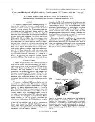
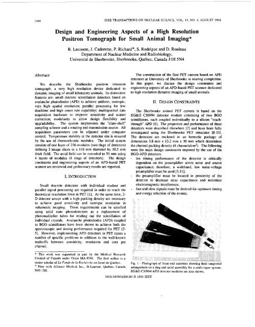
Fig. 1 - Photograph <strong>of</strong> front-end cassettes showing their tangential<br />
arrangement on a ring <strong>and</strong> axial assembly for a multi-layer system.<br />
EG&G C30994 APD detector modules are also shown.
- APD detectors have a narrow optimum operating range<br />
<strong>and</strong>, therefore, must be biased independently:<br />
- access to the detector rim noise <strong>and</strong> energy spectrum is<br />
required for implementing automated detector tuning<br />
procedures [ 101;<br />
- a steady temperature (within less than l°C) must be.<br />
maintained at the detector site because <strong>of</strong> the temperature<br />
dependence <strong>of</strong> the APD gain.<br />
Modularity was another major requirement to facilitate<br />
servicing <strong>and</strong> allow design flexibility <strong>and</strong> upgradability.<br />
Finally, strong emphasis was placed on computer control <strong>of</strong><br />
calibration, setup <strong>and</strong> fault detection in system design.<br />
111. SYSTEM DESCRIPTION<br />
A. Tomograph Configuration<br />
The detector modu1.e~ are physically <strong>and</strong> logically<br />
grouped into cassefres which also incorporate the front-end<br />
electronics. Cassettes include 8 modulesflayer forming a 2 x<br />
8 detector array <strong>and</strong> they can be assembled into "blocks" <strong>of</strong><br />
several layers (Fig. 1). The dimensions <strong>and</strong> shape <strong>of</strong> the<br />
cassettes are such that they can be used in the construction <strong>of</strong><br />
various diameter rings without modification. The animal<br />
tomograph utilizes 32 cassettes (256 detectordring) on a 3 10<br />
mm diameter cylinder. 'The cassettes are further organized<br />
into groups <strong>of</strong> four which are made coincident with three<br />
opposing groups over the ring, thus defining 12 coincident<br />
pairs over a 118 mm diameter UFOV (Fig. 2). The port<br />
diameter is 135 mm, which is suitable for small laboratory<br />
animals such as rats, rabbits or the brain <strong>of</strong> small monkeys.<br />
Since each layer <strong>of</strong> modules consists <strong>of</strong> two adjacent rings <strong>of</strong><br />
detectors, three image planes (two direct, one cross) are<br />
defined within a 10.5 mm thick transaxial slice. The design<br />
characteristics <strong>of</strong> the animal tomograph are summarized in<br />
Table I.<br />
Fig. 2 - Geometry <strong>of</strong> the animal tomograph. The ring is divided<br />
into 8 groups, each made <strong>of</strong> 4 cassettes with 8 modules/layer. Each<br />
group is in coincidence with 3 opposing groups. Only LORs<br />
crossing UFOV are useful to the image.<br />
1447<br />
Table I<br />
Physical description <strong>of</strong> the Sherbrooke animal tomograph<br />
Detector type<br />
Number <strong>of</strong> detectors<br />
BGO crystal size<br />
Module dimensions<br />
BGO crystal spacing<br />
Number <strong>of</strong> detector rings<br />
Ring diameter<br />
Port diameter<br />
Useful field-<strong>of</strong>-view<br />
Shielding gap width<br />
Reconstruction planes<br />
Sampling<br />
Number <strong>of</strong> LORs - total<br />
- useful<br />
EG&G C30994, low-k<br />
256 1 ring<br />
5 12 1 layer <strong>of</strong> modules<br />
3 x 5 x 20 mm (beveled)<br />
3.8 x 13.2 x 33 mm<br />
3.8 mm in-plane<br />
5.5 & 7.7 mm axially<br />
2 to 8<br />
(1 to 4 layers <strong>of</strong> modules)<br />
310 mm<br />
135 mm<br />
118 mm<br />
10.5 - 50 mm<br />
3 (2 direct, 1 cross) per layer<br />
"clam-shell''<br />
24,576 / plane 98,304 1 layer<br />
16,384 / plane 65,536 1 layer<br />
B. Electronics<br />
The tomograph electronics is distributed between the<br />
front-end cassettes installed in the gantry, the processing <strong>and</strong><br />
control functions housed in FASTBUS crates <strong>and</strong> the<br />
acquisition system located in an industrial FT computer.<br />
Fig. 3 illustrates the system architecture.<br />
The front-end cassettes (for one layer) include 16<br />
channels shared between two 8-layer dual-side surface-<br />
mount printed circuit cards. Each channel consists <strong>of</strong> a<br />
MOSFET-based charge sensitive preamplifier <strong>and</strong> fast/slow<br />
shaping amplifiers [ 11,121. The cassettes also include<br />
analog summing circuits to provide a single total energy<br />
signal per module, individual APD rms noise monitors with<br />
associated readout logic, a common test input <strong>and</strong> a<br />
temperature sensor. The power consumption is about 600<br />
mW per channel or 10 W for the cassette.<br />
The shaped analog signals from the front-end are brought<br />
through miniature coaxial ribbon cables to three external<br />
FASTBUS crates housing a total <strong>of</strong> 67 boards <strong>of</strong> eight<br />
different types:<br />
- 16 discriminator boards, each containing 32 constant<br />
fraction discriminators (CFD). The CFD timing pulse<br />
(DTP) is used to trigger the energy processing cycle <strong>and</strong> is<br />
routed to the coincidence units for time validation.<br />
- 32 energy processor boards, each containing 8 channels<br />
<strong>of</strong> a gated integrator, ADC <strong>and</strong> digital single channel<br />
analyzer (SCA). The boards contain encoder/multiplexer<br />
circuitry to generate a common timing pulse for the<br />
cassette (DTP-c), a 5-bit crystal address (ADD.C) <strong>and</strong> 8<br />
bits <strong>of</strong> energy data (ENR-c). Programmable delay lines<br />
were also inserted to compensate for propagation time<br />
differences <strong>of</strong> the DTP signal between channels.<br />
- 4 encoder boards, each concentrating the data from two<br />
groups <strong>of</strong> detectors.
1448<br />
FRONT-END<br />
____-_----<br />
FASTBUS CRATES COMPUTER<br />
___--___-_<br />
DlSCRlMINATOR<br />
HIGH VOLTAGE<br />
Fig. 3 - Block diagram <strong>of</strong> the APD PET scanner electronics. The number <strong>of</strong> boards are indicated for a one-layer animal tomograph (256<br />
modules, 512 detectors). CSP: charge sensitive preamplifier; E analog sum <strong>of</strong> energy signals; DTP: timing signal; ADD: detector address;<br />
ENR: energy data. The extensions -M, -C <strong>and</strong> -G refer to the module, cassette <strong>and</strong> group data, respectively.<br />
- Two multiplexer boards routing the data from the 8<br />
groups <strong>of</strong> detectors into 12 coincidence units as required<br />
by the 12 coincidence pairs.<br />
- 3 coincidence processor boards, each containing 4<br />
coincidence units. Each unit incorporates an on-time<br />
window for true coincidence detection <strong>and</strong> a delayed time<br />
window for r<strong>and</strong>om coincidences. A r<strong>and</strong>om coincidence<br />
flag <strong>and</strong> up to 5 bits <strong>of</strong> physiological information are<br />
inserted into the data stream on the board to form 36-bit<br />
data words which are stored into 512-word deep FIFOs.<br />
The sampling position flag <strong>and</strong> a 2-bit code identifying<br />
the coincidence unit are added on emptying the FIFO into<br />
-<br />
-<br />
the acquisition system located in the PC computer.<br />
8 <strong>high</strong>-voltage control boards providing individual bias to<br />
the 512 APD detectors with a precision <strong>of</strong> about 2 volts.<br />
A common stable voltage reference <strong>and</strong> safety protection<br />
circuits were implemented on a separate board.<br />
One control board implementing the control signals <strong>and</strong><br />
I/O bus to read/write parameters into DACs <strong>and</strong> LUTs<br />
distributed on the other FASTBUS boards.<br />
A total <strong>of</strong> 2824 parameters per layer <strong>of</strong> modules must be<br />
loaded to set-up the AF'D bias, the CFD noise threshold, the<br />
ADC reference conversion gain, the energy lower <strong>and</strong> upper<br />
thresholds, the delay compensation <strong>and</strong> the time coincidence<br />
window width. In order to facilitate calibration <strong>and</strong><br />
troubleshooting, it is possible to enable or inhibit individual<br />
detectors, modules, cassettes or groups.<br />
The acquisition system was designed to allow on-line<br />
histogramming <strong>of</strong> the dah with maximum throughput <strong>and</strong><br />
<strong>high</strong> flexibility. In addition to the st<strong>and</strong>ard data acquisition<br />
modes (static, dynamic/gated, sampling,...), provision was<br />
made for:<br />
- simultaneous acquisition <strong>of</strong> the direct or coincidence<br />
IX, -Am<br />
energy spectra from all detectors for calibration, set-up<br />
<strong>and</strong> diagnostic purposes;<br />
- multispectral data acquisition whereby the coincident<br />
events are recorded in up to 16x16 energy windows [13].<br />
This was achieved by using three parallel fully<br />
programrnable data selectors directly interfaced to three<br />
RISC processors (AMD 29K), each with a 16 MB memory<br />
histogramming capacity. The data selectors are based on<br />
field programmable gate arrays (Xilinx, XC3030) <strong>and</strong> their<br />
function is to select <strong>and</strong> rearrange up to 24 out <strong>of</strong> the 39 bits<br />
<strong>of</strong> information supplied by the coincidence units. The<br />
processed data are then sorted <strong>and</strong> histogrammed in real time<br />
by the RISC processors. Note that only six address bits are<br />
required to code the detector position in groups with the<br />
present single-layer implementation <strong>of</strong> the system. The two<br />
unused bits are available to exp<strong>and</strong> group size in a four-layer<br />
animal scanner or larger ring diameter systems.<br />
C. Gantry<br />
Fig. 4 is a photograph showing the APD animal<br />
tomograph during assembly. A cross section <strong>of</strong> the<br />
mechanical design <strong>of</strong> the scanner with one <strong>and</strong> four layers <strong>of</strong><br />
detector modules is displayed in Fig. 5.<br />
Temperature stability at the detector site was the most<br />
stringent requirement to satisfy in designing the gantry for<br />
the APD tomograph due to the temperature dependence <strong>of</strong><br />
the APD gain [2]. Temperature control in the gantry is<br />
complicated by the heat load from the front-end electronics (<br />
-300 W per layer <strong>of</strong> modules) <strong>and</strong> by the necessity to<br />
maintain proper electromagnetic isolation <strong>of</strong> the front-end.<br />
The heat from the electronics is evacuated by circulating<br />
forced air between the circuit boards. A method previously<br />
developed for the Sherbrooke PET simulator was used to
Fig. 4 - Photograph <strong>of</strong> the APD animal tomograph during assembly<br />
with one <strong>of</strong> the front half-:ring frame removed to show the<br />
cassettes.<br />
cu<br />
Pb<br />
Fig. 5 - Cross section showing the mechanical design <strong>of</strong> the animal<br />
PET scanner with a single (top) <strong>and</strong> four (bottom) layers <strong>of</strong><br />
detector modules.<br />
1449<br />
provide a stable detector temperature [ 141: twelve<br />
thermoelectric cooling modules (Melcor CP1.4- 127, Trenton<br />
NJ) fixed to the lead shields on either side <strong>of</strong> the ring are<br />
used to slightly cool the detectors below ambient<br />
temperature (typically 18°C). Water-cooled heat sinks<br />
remove the heat generated by the thermoelectric modules.<br />
Temperature sensors on each half <strong>of</strong> the annular lead shields<br />
(4 in total) are connected in closed loop to simple custom-<br />
made digital remote control systems which are capable <strong>of</strong><br />
keeping the temperature constant within HI. 1°C over<br />
extended periods <strong>of</strong> time. The lead shields were copper-<br />
plated on both surfaces to ensure good thermal contact <strong>and</strong><br />
uniform temperature all over the detector ring. The shield<br />
mass provides sufficient inertia to withst<strong>and</strong> rapid ambient<br />
temperature changes without any significant effect on the<br />
detectors. Nylon screws <strong>and</strong> rubber spacers were used to<br />
electrically isolate the shields (<strong>and</strong> detectors) from the ring<br />
frame.<br />
Since the intrinsic detector <strong>resolution</strong> is 1.9 mm FWHM<br />
<strong>and</strong> the linear sampling distance in stationary mode is also<br />
1.9 mm, the sampling density must be increased by at least a<br />
factor <strong>of</strong> two to reach the <strong>resolution</strong> limit <strong>of</strong> the system. The<br />
"clam-shell'' motion scheme was retained [15]. The ring<br />
frame supporting the detectors <strong>and</strong> electronics is separated in<br />
two halves which are suspended to a clam pivot aligned with<br />
the detectors on the upper side <strong>of</strong> the ring. The clam action<br />
mechanism is based on a worm screw driving toggle arms<br />
attached to the bottom <strong>of</strong> the two ring halves (see Fig. 6). A<br />
smooth, continuous motion, free <strong>of</strong> mechanical shocks <strong>and</strong><br />
vibrations is achieved using a stepper motor. The<br />
positioning accuracy is very <strong>high</strong> (
1450<br />
Provision was made for exp<strong>and</strong>ing the axial field <strong>of</strong> the<br />
tomograph to 50 mm by inserting additional layers <strong>of</strong><br />
modules (see Fig. 5). Therefore, the supporting frame, the<br />
cable ducts <strong>and</strong> the heat management capabilities were<br />
designed to accommodate up to four layers <strong>of</strong> modules (8<br />
rings <strong>of</strong> detectors). The front shield collimator is adjustable<br />
<strong>and</strong> can easily be removed to insert or remove inter-slice<br />
septa. In the current single layer system, no slice septa has<br />
been installed between the two rings <strong>of</strong> detectors.<br />
The whole ring assembly can be tilted +90°/-300 relative<br />
to the vertical to facilitate selection <strong>of</strong> imaging planes<br />
through the subject <strong>and</strong> to permit imaging <strong>of</strong> phantoms<br />
immersed in a jar in the upright position.<br />
IV. PRELIMINARY RESULTS<br />
The design performance characteristics <strong>of</strong> the APD<br />
animal tomograph are summarized in Table 11. Preliminary<br />
results were obtained using the Sherbrooke PET simulator<br />
[14], set up with the same geometry <strong>and</strong> equipped with the<br />
same front-end <strong>and</strong> processing electronics as the animal PET<br />
camera. All measurements reported here were taken with the<br />
lower energy threshold set at 350 keV on each detector <strong>and</strong> a<br />
coincidence timing window <strong>of</strong> 40 ns.<br />
A. Spatial Resolution<br />
Spatial <strong>resolution</strong> was measured using a 0.85 mm<br />
diameter 22Na line source. Examples <strong>of</strong> the in-plane <strong>and</strong><br />
axial coincidence responses obtainable with the scanner are<br />
shown in Figs. 7 <strong>and</strong> 8, respectively. These data were not<br />
corrected for r<strong>and</strong>oms <strong>and</strong> detection efficiency. As can be<br />
observed from these distributions, individually coupled<br />
detectors yield sharp, undistorted responses which follow<br />
rather closely the expected geometric response functions <strong>of</strong><br />
the crystals. The overlap between response functions <strong>of</strong><br />
adjacent parallel LORs is less than 20% <strong>of</strong> the maximum<br />
height in the central region <strong>of</strong> the field. The slight<br />
asymmetry <strong>of</strong> the base <strong>of</strong> the axial response for the direct<br />
planes in Fig. 8 is due to the absence <strong>of</strong> septa between the<br />
Table I1<br />
<strong>Design</strong> performance characteristics <strong>of</strong> the<br />
Sherbrooke animal tomograph<br />
Spatial <strong>resolution</strong> (center)<br />
Intrinsic: Transaxial 1.9 mm FWHM, 3.5 mm FWTM<br />
Axial 3.1 mm FWHM, 5.4 mm FWTM<br />
Reconstructed 2.1 mm FWHM, 3.9 mm FWTM<br />
Absolute efficiency 0.4 Yo<br />
Sensitivity 3.3 kcps/pCi/ml<br />
(1 lcm0 flood, 350 keV)<br />
Energy <strong>resolution</strong> 125% FWHM (511 keV)<br />
Timing <strong>resolution</strong> 15-20ns FWHM<br />
Timing window 20 to 40 ns<br />
W<br />
2<br />
a<br />
I-<br />
z<br />
9<br />
8<br />
W<br />
E<br />
4<br />
W<br />
U<br />
1000<br />
800<br />
600<br />
400<br />
200<br />
0<br />
5 10 15 20<br />
SOURCE POSITION (mm)<br />
Fig. 7 - Transaxial response functions for three parallel LORs at a<br />
distance <strong>of</strong> 10-20 mm from the center measured by sweeping the<br />
line source radially in the field.<br />
I-<br />
z<br />
3<br />
8 1000<br />
W<br />
2<br />
I-<br />
4 500<br />
W<br />
U<br />
0<br />
-10 % -6 -4 -2 0 2 4 6 8 1<br />
SOURCE POSITION (mm)<br />
Fig. 8 - Axial response functions <strong>of</strong> the two direct planes <strong>and</strong> <strong>of</strong> the<br />
cross slice defined by one layer <strong>of</strong> detector modules. The pr<strong>of</strong>iles<br />
were measured by moving the line source axially midway between<br />
diametrically opposite detectors.<br />
two crystals in the same module <strong>and</strong> to the energy validation<br />
performed on the summed signal from the two crystals.<br />
Spatial <strong>resolution</strong> data measured in the reconstructed<br />
images <strong>and</strong> in the axial direction are summarized in Figs. 9<br />
<strong>and</strong> 10. The <strong>resolution</strong> in-slice (Fig. 9) was measured from<br />
images acquired by a double sampling method described<br />
previously [ 161 <strong>and</strong> reconstructed by filtered backprojection<br />
with a ramp filter <strong>of</strong> cut-<strong>of</strong>f frequency 5.3 cm-'.<br />
B. Sensitivity<br />
An event rate <strong>of</strong> 70 cps/pCi/cm, corresponding to an<br />
absolute efficiency <strong>of</strong> about 0.4%, was measured with the<br />
22Na line source placed axially in the center <strong>of</strong> the field.<br />
The sensitivity measured with a 11 cm diameter flood is 0.8,<br />
1.7 <strong>and</strong> 3.3 kcps/pCi/ml for the direct planes, cross plane <strong>and</strong><br />
full layer <strong>of</strong> dual detector modules, respectively. These data<br />
were corrected for r<strong>and</strong>oms, but not for scatter radiation.
e<br />
'1<br />
6<br />
2 4<br />
23<br />
8<br />
w2<br />
a<br />
Fig. 9 - Radial <strong>and</strong> tangential <strong>resolution</strong> in the reconstructed image<br />
measured using a 0.85 mm diameter line source <strong>of</strong> 22Na.<br />
7<br />
't<br />
, , . .<br />
0 1 2 3 4 5 6<br />
DISTANCEFROMCPCIEA (an)<br />
Fig. 10 - Axial <strong>resolution</strong> as a. function <strong>of</strong> distance from the center.<br />
C. Scatter<br />
In a <strong>high</strong> <strong>resolution</strong> tomograph based on small discrete<br />
detectors, a scatter component originating from the detection<br />
system can be identified in addition to the object scatter<br />
component [ 171. The scatter distributions were estimated<br />
from the projections measured with the 22Na line source in<br />
air <strong>and</strong> in a 11 cm diameter by 2.54 cm thick Plexiglas<br />
cylinder. The scatter within the peak was estimated by<br />
extrapolating the scatter distributions fitted with<br />
monoexponentials under the peak. With the 350 keV<br />
threshold, the detector <strong>and</strong> object scatter fractions<br />
(scatter/total) at the center are 24% <strong>and</strong> 17%, respectively.<br />
Since the detector scatter component is confined to a narrow<br />
region around the peak (-2 cm), these events would<br />
conventionally be considered as true events. Note that the<br />
object scatter fraction measured at the center <strong>of</strong> a 11 cm<br />
diameter cylinder is a worst case for this scanner. The<br />
scatter fraction determined following the SNM/NEMA<br />
recommendation [18] is estimated to be less than 7%.<br />
145 1<br />
D. Count rate<br />
The data processing <strong>and</strong> acquisition circuits have not<br />
been tested as yet with the full detection system. Thus, we<br />
can only make general comments about the count rate<br />
performance at this time. The overall count rate capability is<br />
the result <strong>of</strong> limitations in the detector front-end, address<br />
encoding circuits <strong>and</strong> data acquisition system [ 191. Thus far,<br />
only the detector front-end <strong>and</strong> part <strong>of</strong> the encoding circuits<br />
were investigated.<br />
The front-end maximum throughput for a dual detector<br />
module is determined by the 2.2 p energy processing cycle.<br />
However, the effective event rate is affected by the noise<br />
threshold <strong>of</strong> the CFD which is used to trigger the energy<br />
cycle: if the noise threshold is too <strong>high</strong>, useful events are<br />
lost: if it is too low, the circuit deadtime becomes important<br />
<strong>and</strong> the rate <strong>of</strong> r<strong>and</strong>om events due to electronic noise<br />
increases. In addition, accidental pulses due to electronic<br />
noise may invalidate useful events which will be rejected by<br />
the coincidence timing window. Initial experiments with the<br />
PET simulator have shown that a CFD noise rate <strong>of</strong> the order<br />
<strong>of</strong> 2-5 kcps per detector is optimum [lo]. Thus, deadtime<br />
due to noise in the front-end is typically on the order <strong>of</strong> 2%<br />
or less.<br />
Deadtime also arises from the address encoding circuits<br />
which concentrate the timing pulses, reject multiple events,<br />
compensate for propagation differences <strong>and</strong> generate the<br />
crystal address. This is performed in two steps for the<br />
crystal address in the cassette (0.55 p) <strong>and</strong> cassette address<br />
in the group (0.135 ps). Assuming an energy-validated<br />
event rate <strong>of</strong> 5 kcps per detector, which is considerably<br />
<strong>high</strong>er than most planned investigations, the deadtime due to<br />
encoding is less than 10%.<br />
Each coincidence unit accepts the timing pulses from two<br />
groups <strong>and</strong> determines the true (on-time) <strong>and</strong> r<strong>and</strong>om (<strong>of</strong>f-<br />
time) coincidences. This is performed in about 105 ns.<br />
Since the timing pulses are generated at a minimum interval<br />
<strong>of</strong> 135 ns by the group encoders, no deadtime is introduced<br />
by the coincidence units. This is the last real time operation<br />
<strong>of</strong> the data acquisition process. The validated coincident<br />
event addresses are stored in FIFOs which are subsequently<br />
unloaded at a total maximum speed <strong>of</strong> about 1.2 MHz.<br />
For a singles rate <strong>of</strong> 2 kcps per detector, the fraction <strong>of</strong><br />
accidental coincidences (accidentals/trues) was measured as<br />
10% with the 40 ns coincidence timing window. Using the<br />
design timing window <strong>of</strong> 30 ns, it can be extrapolated that a<br />
50% accidental fraction will be reached for a system trues<br />
rate <strong>of</strong> the order <strong>of</strong> 500 kcps or a total singles rate in excess<br />
<strong>of</strong> 5 Mcps.<br />
V. CONCLUSION<br />
The first PET scanner using solid state photodetectors as<br />
a replacement <strong>of</strong> the photomultiplier tubes has been<br />
developed <strong>and</strong> its major design characteristics have been<br />
described. In spite <strong>of</strong> several specific design constraints, the<br />
implementation has been demonstrated to be technically
1452<br />
feasible <strong>and</strong> economically within reach for instruments <strong>of</strong><br />
this class. The APD scanner achieves a nearly isotropic<br />
volumetric <strong>resolution</strong> <strong>of</strong> the order <strong>of</strong> 0.015 cc ", a<br />
factor <strong>of</strong> at least 2 better than all existing tomographs. In<br />
providing functional images <strong>of</strong> unprecedented definition, this<br />
new device will be an important research tool for small<br />
animal studies.<br />
VI. ACKNOWLEDGEMENTS<br />
We thank S. Setian <strong>and</strong> I. Stark for contributions to the<br />
mechanical design <strong>of</strong> the gantry <strong>and</strong> ISIS Inc. (Lachine, QC)<br />
for financial support during its construction. The authors<br />
would like to express their appreciation to all those who<br />
contributed, over the years, to the design <strong>and</strong> development <strong>of</strong><br />
this tomograph.<br />
VII. REFERENCES<br />
W.W. Moses <strong>and</strong> S.E. Derenzo, "Empirical observation <strong>of</strong><br />
<strong>resolution</strong> degradation in <strong>positron</strong> emission tomographs<br />
utilizing block detectors", J. Nucl. Med., vol. 34, p. lOlP,<br />
1993.<br />
R. Lecomte, D. Schmitt. R.J. McIntyre <strong>and</strong> A. Lightstone,<br />
"Performance characteristics <strong>of</strong> BGO-silicon avalanche<br />
photodiode detectors for PET', IEEE Trans. Nucl. Sci.. vol.<br />
NS-32, pp. 482-486, 1985.<br />
C. Carrier <strong>and</strong> R. Lecomte, "Recent results in scintillation<br />
detection with silicon avalanche photodiodes", IEEE Trans.<br />
Nucl. Sci., VO~. 37, pp. 209-214, 1990.<br />
C. Carrier <strong>and</strong> R. Lecomte, "Timing performance <strong>of</strong><br />
scintillators read out by silicon avalanche photodiodes", Nucl.<br />
Instrum. Meth. Phys. Res., vol. A299, pp. 115-1 18, 1990.<br />
D.M. Binkley, J.M. Rochelle, M.J. Paulus <strong>and</strong> M.E. Casey,<br />
"A low-noise, wideb<strong>and</strong>, integrated CMOS transimpedance<br />
preamplifier for photodiode applications", IEEE Trans. Nucl.<br />
Sci., vol. 39, pp.747-752, 1992.<br />
A.W. Lightstone, R.J. McIntyre, R. Lecomte <strong>and</strong> D. Schmitt,<br />
"A bismuth germanate-avalanche photodiode module<br />
designed for use in <strong>high</strong> <strong>resolution</strong> <strong>positron</strong> emission<br />
tomography", IEEE Trans. Nucl. Sci., vol. NS-33, pp. 456-<br />
459, 1986.<br />
R. Lecomte, C. Martel <strong>and</strong> C. Carrier, "Status <strong>of</strong> BGO-avalanche<br />
photodiode detectors for spectroscopic <strong>and</strong> timing<br />
measurements", Nucl Instrum. Meth. Phys. Res., vol. A278,<br />
pp. 585-597, 1989.<br />
R. Lecomte, J. Cadorette, M. HOon, D. Rouleau <strong>and</strong> G. Gauthier,<br />
"High <strong>resolution</strong> <strong>positron</strong> emission tomography with a<br />
prototype camera based on solid state scintillation detectors",<br />
IEEE Trans. Nucl. Sa., vol. 37, pp. 805-81 1,1990.<br />
R. Lecomte, C. Martel <strong>and</strong> J. Cadorette, "Study <strong>of</strong> the <strong>resolution</strong><br />
performance <strong>of</strong> an array <strong>of</strong> discrete detectors with independent<br />
readouts for <strong>positron</strong> emission tomography", IEEE<br />
Trans. Med. Imag.,vol. 10,pp. 347-357.1991.<br />
J. Cadorette, S. Rodrigue <strong>and</strong> R. Lecomte, "Tuning <strong>of</strong><br />
avalanche photodiode PET camera", IEEE Trans. Nucl. Sci.,<br />
VO~. 40, pp. 1062-1066. 1993.<br />
D. Schmitt, R. Lecomte, M. Lapointe et al., "Ultra-low noise<br />
charge sensitive preamplifier for scintillation detection with<br />
avalanche photodiodes in PET applications", IEEE Trans.<br />
Nucl. Sci., vol. NS-34. pp. 91-96, 1987.<br />
1121 P. Richad, D. Rouleau, S. Rodrigue et al., "<strong>Design</strong> <strong>and</strong><br />
performance <strong>of</strong> the front-end processing electronics for a<br />
PET tomograph based on BGO-avalanche photodiode<br />
detectors", Nucl. Instrum. Meth. Phys. Res, A (to be<br />
published).<br />
[13] R. Lecomte, M. Bentourkia, P. Msaki et al., "Potentials <strong>of</strong><br />
multispectral acquisition in <strong>positron</strong> emission tomography",<br />
Con$ Rec. 1992 IEEE Nuclear Science Symposium <strong>and</strong><br />
Medical Imaging Conference, IEEE Catalog No. 92CH3232-<br />
6, VO~. 2, pp. 856-858.<br />
141 R. Lecomte, J. Cadorette, S. Rodrigue et al., "A PET camera<br />
simulator with multispectral data acquisition capabilities",<br />
IEEE Trans. Nucl. Sci., vol. 40, pp.1067-1074, 1993.<br />
151 R.H. Huesman, S.E. Derenzo <strong>and</strong> T.F. Budinger, "A twoposition<br />
sampling scheme for <strong>positron</strong> emission<br />
tomography", in Proc. 3rd World Congress <strong>of</strong> Nuclear<br />
Medicine <strong>and</strong> Biology, ed. C. Raynaud, NY:Pergamon, 1982,<br />
pp. 542-545.<br />
[16] M. HCon, C. Carrier, J. Cadorette et al., "A stationary<br />
sampling scheme for multilayer <strong>positron</strong> tomographs", IEEE<br />
Trans. Med. Imag.. vol. 12, pp. 293-298,1993.<br />
[17] M. Bentourkia, P. Msaki, J. Cadorette et al., "Assessment <strong>of</strong><br />
scatter components in a very <strong>high</strong> <strong>resolution</strong> PET scanner", J.<br />
Nucl. Med., vol. 34, p. 136P, 1993.<br />
[18] J.S.Karp, M.E. Daube-Witherspoon, E.J. H<strong>of</strong>fman et al.,<br />
"Performance st<strong>and</strong>ards in <strong>positron</strong> emission tomography",<br />
J. Nucl. Med., vol. 32, pp. 2342-2350, 1991.<br />
[19] C.J. Thompson <strong>and</strong> E. Meyer, "The effect <strong>of</strong> live time in<br />
components <strong>of</strong> a <strong>positron</strong> tomograph on image<br />
quantification", IEEE Trans. Nucl. Sci., vol. NS-34, pp. 337-<br />
343, 1987.