DMX-ADDRESS-MODULE - DMX4ALL GmbH
DMX-ADDRESS-MODULE - DMX4ALL GmbH
DMX-ADDRESS-MODULE - DMX4ALL GmbH
- No tags were found...

You also want an ePaper? Increase the reach of your titles
YUMPU automatically turns print PDFs into web optimized ePapers that Google loves.
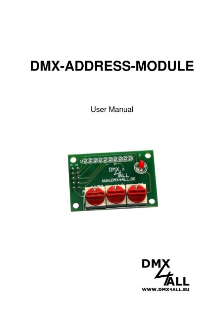
<strong>DMX</strong>-<strong>ADDRESS</strong>-<strong>MODULE</strong>User Manual
<strong>DMX</strong>-Address-Module 2SpecificationThe <strong>DMX</strong>-Address-Module is a useful add-on, which can be connected to the <strong>DMX</strong>data line. A starting address of any <strong>DMX</strong> device, which is connected behind the<strong>DMX</strong>-Address-Module, can be centrally adjusted by it.The <strong>DMX</strong> devices, which are connected behind the <strong>DMX</strong>-Address-Module, react totheir adjusted starting address plus the address of the <strong>DMX</strong>-Address-Module minusone.Resulting address = <strong>DMX</strong>-Address-Module address + device address - 1Example:<strong>DMX</strong>-Address- Device address Resulting addressModule address1 1 115 1 151 15 1515 15 29Note: If only one <strong>DMX</strong> device is be driven by the <strong>DMX</strong>-Address-Module the startingaddress of this device should be set to one, so the resulting address is equal to theaddress of the <strong>DMX</strong>-Address-ModuleExample of a configuration with 2x 6 <strong>DMX</strong> controlled outputs and one centrallyadjusted <strong>DMX</strong> address by the <strong>DMX</strong>-Address-Module:
<strong>DMX</strong>-Address-Module 3Data SheetVoltage supply:<strong>DMX</strong>-input:<strong>DMX</strong>-channels:<strong>DMX</strong>-output:Envelope delay:Board Dimension:5V DC / 50mA<strong>DMX</strong>-signal / 1 LOAD-UNITnone<strong>DMX</strong>-signal for 32 LOAD-Unitsca. 0,1µs30mm x 45mmLED-Display-CodesThe integrated <strong>DMX</strong>-LED is used as a multifunctional display.This LED lights nonstop in normal operation. If the LED does not light, there is no<strong>DMX</strong>512-input-signal.Also the LED signalled the operation status. In this case the LED lights up in shortpitches and then turns into off modus. The Number of flashing signals is equal tothe Number of the error status:Error ErrorDescriptionStatus1 No <strong>DMX</strong> Please check the <strong>DMX</strong> signal2 Address error Check if a valid <strong>DMX</strong>-starting address isadjusted.3 <strong>DMX</strong>-signal error An invalid <strong>DMX</strong> input signal is established.
<strong>DMX</strong>-<strong>ADDRESS</strong>-<strong>MODULE</strong> Connectors<strong>DMX</strong>-Address-Module 4PIN FUNKTION PIN FUNKTION1 GND 2 +5V IN3 GND 4 GND5 <strong>DMX</strong>+ IN 6 <strong>DMX</strong>+ OUT7 <strong>DMX</strong>- IN 8 <strong>DMX</strong>- OUT9 SDA 10 SCL+5VGND21GND<strong>DMX</strong>+ OUT<strong>DMX</strong>- OUTGND<strong>DMX</strong>+ IN<strong>DMX</strong>- INBack view of the <strong>DMX</strong>-Address-Module
<strong>DMX</strong>-Address-Module 5TWI-InterfaceThe adjusted value of the <strong>DMX</strong>-Address-Module can be readout by the TWI-Interface. The SDA- and SCL- connector can establish a connection to use the TWIInterface.+5VGND21SDASCLBack view of the <strong>DMX</strong>-Address-ModuleAddressingThe <strong>DMX</strong>-Address-Module comes with the hardware address 0b0100111x. The lastbit R/W must be set so the <strong>DMX</strong>-Address-Module data can be readout.Timing DiagramSCLStart conditionR/WACK from slave ACK from master ACK from masterSlave address (<strong>DMX</strong>880)SDAS 0 1 0 0 1 1 1 1 A D7 D6 D5 D4 D3 D2 D1 D0 A D15 D14 D13 D12 D11 D0 D10 D9 D8 A
<strong>DMX</strong>-ADRESS-<strong>MODULE</strong> Dimensions:<strong>DMX</strong>-Address-Module 6414436,8312,7 10,1610,1635xd=32720,70 0 03303xd=105,5All details in mm
<strong>DMX</strong>-Address-Module 7CE-conformityThis assembly (board) is controlled by a microprocessor and uses high frequency. Toget the characteristics of the assembly in relation to the CE-conformity, an installationin a compact metal casing is necessary.Risk-NotesYou purchased a technical product. Conformable to the best available technology thefollowing risks should not excluded:Failure risk: The device can drop out partially or completely at any time withoutwarning. To reduce the probability of a failure a redundant system structure isnecessary.Initiation risk: For the installation of the board, the board must be connected andadjusted to foreign components according to the device paperwork. This work canonly be done by qualified personnel, which read the full device paperwork andunderstand it.Operating risk: The Change or the operation under special conditions of theinstalled systems/components could as well as hidden defects cause to breakdownwithin the running time.Misusage risk: Any nonstandard use could cause incalculable risks and is notallowed.Warning: It is not allowed to use the device in an operation, where the safety ofpersons depends on this device.
<strong>DMX</strong>4ALL <strong>GmbH</strong>Reiterweg 2AD-44869 BochumGermany© Copyright 2012 <strong>DMX</strong>4ALL <strong>GmbH</strong>All rights reserve. No part of this manual may be reproduced in any form (photocopy, pressure, microfilm or inanother procedure) without written permission or processed, multiplied or spread using electronic systems.All information contained in this manual was arranged with largest care and after best knowledge. Neverthelesserrors are to be excluded not completely. For this reason I see myself compelled to point out that I can take overneither a warranty nor the legal responsibility or any adhesion for consequences, which decrease/go back toincorrect data. This document does not contain assured characteristics. The guidance and the characteristicscan be changed at any time and without previous announcement.