PXL-250 Tiger Controller PXL-250 Quick Start Guide - Keri Systems
PXL-250 Tiger Controller PXL-250 Quick Start Guide - Keri Systems
PXL-250 Tiger Controller PXL-250 Quick Start Guide - Keri Systems
- No tags were found...

Create successful ePaper yourself
Turn your PDF publications into a flip-book with our unique Google optimized e-Paper software.
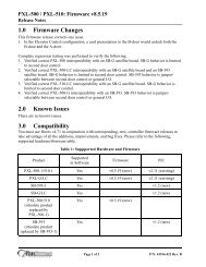
<strong>PXL</strong>-<strong>250</strong> <strong>Tiger</strong> <strong>Controller</strong>This quick start guide provides, basic installation information, drawings, first time power-on instructions, and shortdescriptions of key terms and concepts for installing controllers. For comprehensive information regarding the<strong>PXL</strong>-<strong>250</strong> <strong>Tiger</strong> <strong>Controller</strong>, please refer to the Technical Reference (P/N 01836-004).NOTE: It is the responsibility of the installation organization to have only technically qualified personnelperforming the installation.<strong>Quick</strong> <strong>Start</strong> <strong>Guide</strong>Figure 1: The <strong>PXL</strong>-<strong>250</strong> <strong>Controller</strong><strong>PXL</strong>-<strong>250</strong>Unit 17 Park Farm Industrial Estate 01835-002 Rev. 4.2Buntingford, Herts SG9 9AZ UKTEL: 0870 444 7234 FAX: 0870 444 7240Web: http://www.kerisystems.co.uk E-mail: sales@kerisystems.co.uk Page 1 of 22
<strong>PXL</strong>-<strong>250</strong> <strong>Tiger</strong> <strong>Controller</strong><strong>Quick</strong> <strong>Start</strong> <strong>Guide</strong>1.0 SpecificationsUnit Dimensions• <strong>PXL</strong>-<strong>250</strong> controller PCB- 6.75 inches high by 6.00 inches wide by 1.75 inches deep, including wiring connectors- (17.15 cm by 15.25 cm by 4.45 cm)• <strong>PXL</strong>-<strong>250</strong> controller PCB with an SB-293 Satellite Board- 7.25 inches high by 6.00 inches wide by 1.75 inches deep, including wiring connectors- (18.45 cm by 15.25 cm by 4.45 cm)• <strong>PXL</strong>-<strong>250</strong> controller PCB with an LCD-1 Alpha/Numeric Display- 7.70 inches high by 6.00 inches wide by 1.75 inches deep, including wiring connectors- (19.60 cm by 15.25 cm by 4.45 cm)• <strong>PXL</strong>-<strong>250</strong> controller PCB with an SB-293 Satellite Board and an LCD-1 Alpha/Numeric Display- 8.10 inches high by 6.00 inches wide by 1.75 inches deep, including wiring connectors- (20.60 cm by 15.25 cm by 4.45 cm)• Enclosure- 9.70 inches high by 8.20 inches wide by 2.60 inches deep- (24.65 cm by 20.85 cm by 6.60 cm)Operating Temperature/Humidity Range• 0°F to 140°F (-18°C to 60°C)• 0% to 90% Relative Humidity, non-condensing<strong>Controller</strong> Power Requirements• 12 VDC @ 1 ACurrent Draw• maximum current draw 270 mA for a controller plus reader current draw (refer to Table 1 for Reader currentdraw)• 120 mA max for a <strong>PXL</strong>-<strong>250</strong> <strong>Controller</strong>• 150 mA max for an SB-293 Satellite BoardTable 1: Reader Current DrawReader Type<strong>PXL</strong>-<strong>250</strong>MS-3000 MS-4000 MS-5000 MS-7000 MS-9000Current Draw 50 mA 50 mA 100 mA 200 mA 200 mANOTE: If an electronic locking device (such as a magnetic lock, a door strike, or similar device) is to be driven bythe same power supply as the <strong>PXL</strong>-<strong>250</strong> controller, please ensure the power supply provides enough current to driveevery device connected to that supply plus an adequate safety margin. AC power cannot be used.<strong>Controller</strong> Memory Retention• 5 year lithium battery back up to support controller RAM and real-time clockOutput Relay Contact Rating• 1 Amp @ 24 VDCInput Device Configuration - 3 Inputs• Door Sense normally closed• Request to Exit normally open• Global Unlock normally open, orAuxiliary RTE A-Doornormally openUnit 17 Park Farm Industrial Estate 01835-002 Rev. 4.2Buntingford, Herts SG9 9AZ UKTEL: 0870 444 7234 FAX: 0870 444 7240Web: http://www.kerisystems.co.uk E-mail: sales@kerisystems.co.uk Page 2 of 22
<strong>PXL</strong>-<strong>250</strong> <strong>Tiger</strong> <strong>Controller</strong>2.0 Cable RequirementsRS-232 Serial Cable• four conductor, shielded, stranded, AWG 24 wire (Belden 9534 or a larger gauge)• 50 feet maximum length (per RS-232 industry specification - greater lengths are not recommended)RS-485 Network Cable• two conductor, shielded, twisted pair, stranded, AWG 24 wire (Belden 9501 or a larger gauge)• 16,000 feet total network length• refer to the Network Wiring Application Note (P/N 01824-002) for specific network wiring informationInput Power• two conductor, stranded, AWG 18 wire (Belden 8461 or a larger gauge)• 200 foot maximum length for systems using an SB-293 with two readersNOTE: On long power cable runs, the cable resistance causes a drop in voltage at the end of the cable run. Be sureyour power supply does provide 12 VDC at the end of the cable run.Earth Ground• Single conductor, AWG 18 wire (or a larger gauge) 1<strong>Keri</strong> <strong>Systems</strong> Proximity Readers• six conductor, shielded, stranded, AWG 24 wire (Belden 9536 or a larger gauge)• four conductor, shielded, stranded, AWG 24 wire (Belden 9534 or a larger gauge) for the MS-4000 only (thereis no beeper or LED in the MS-4000)• see Table 2 for maximum cable lengths<strong>Quick</strong> <strong>Start</strong> <strong>Guide</strong>Table 2: Maximum Cable Lengths by Wire Gauge for Proximity ReadersCable Length by Wire GaugeReader Type 100 feet <strong>250</strong> feet 500 feetMS-3000 AWG 24 AWG 24 AWG 24MS-4000 AWG 24 AWG 24 AWG 24MS-5000 AWG 24 AWG 24 AWG 24MS-7000 AWG 24 AWG 24 AWG 20MS-9000 AWG 24 AWG 22 AWG 18<strong>PXL</strong>-<strong>250</strong>Wiegand Compatible Readers• five to seven conductor, shielded, stranded, wire – depending upon the Wiegand reader’s requirements1. Ground wire is green with or without yellow tracer.Unit 17 Park Farm Industrial Estate 01835-002 Rev. 4.2Buntingford, Herts SG9 9AZ UKTEL: 0870 444 7234 FAX: 0870 444 7240Web: http://www.kerisystems.co.uk E-mail: sales@kerisystems.co.uk Page 3 of 22
<strong>PXL</strong>-<strong>250</strong> <strong>Tiger</strong> <strong>Controller</strong><strong>Quick</strong> <strong>Start</strong> <strong>Guide</strong><strong>PXL</strong>-<strong>250</strong>• a minimum gauge of AWG 24 is required for data transfer with a 500-foot maximum run length per Wiegandspecification 1Input and Output Connections• two conductor, stranded, AWG 22 (or a larger gauge)NOTE: The Lock Output relay may require a heavier gauge of wire depending upon the current demands of the lockand the length of the lock wiring run.NOTE: If plenum cable is required, please reference the Belden plenum equivalent to the cables listed above.3.0 When Installing <strong>Controller</strong>sDO• plan ahead to meet power and telephone requirements 2 for your system (1 phone line for the modem connectedto the host computer and one for each master <strong>PXL</strong>-<strong>250</strong> in each network)• mount controllers in environmentally suitable areas - they require protection from weather and fromtemperature/humidity extremes• mount the controller at least 3 feet away from the controller's power supply to prevent EMI radiated from thepower supply from affecting the controller• use the enclosure as a mounting template to mark drilling holes for permanent mounting• consider mounting requirements - central versus distributed- central mounting places all controllers in one location, running lengths of cables out to each door tosupport readers, inputs and outputs- distributed mounting places each controller near the door it supports running short lengths of cable out toeach door, but running a long network communication cable• note the locations of the knockouts in the enclosures and remove the appropriate knockout for the easiest cablerouting into the controller• route all controllers in a network in a single, continuous daisy-chain• route cables in accessible areas for ease of maintenance• connect all controllers to a quality earth ground 3• add transient suppression across electric devices attached to a controller output• use an isolation relay (P/N IRP-1) if attaching to a parking gate, a turnstile, or any application using a largeelectric motor• verify the controller's supply voltage is 12 VDC – long power line runs cause a drop in voltage at the end of therun• verify proper operation of the host computer's COM port• for a single door application, install the reader to the TB-5, "A" reader connection• attach the reader to be used for card enrollment to the master controller (this reader can be used for accesscontrol as well as enrollment, but during the enrollment process the door associated with the enrollment readerwill not allow access until the enrollment process is complete)DO NOT1. The wire gauge to use should be determined by the current draw requirements of the Wiegand deviceand the actual length of the cable run. A +5 VDC and a +12 VDC Wiegand device must have a full +5VDC or +12 VDC at the device (long cable runs have a voltage drop across the length of the run due tothe resistance in the cable). To ensure proper voltage is available at the device a larger gauge of wire(having less resistance) or a power supply at the Wiegand device may be required.2. Phone lines are only needed for remote communication between host computer and network using amodem.3. Ground wire is green with or without yellow tracer.Unit 17 Park Farm Industrial Estate 01835-002 Rev. 4.2Buntingford, Herts SG9 9AZ UKTEL: 0870 444 7234 FAX: 0870 444 7240Web: http://www.kerisystems.co.uk E-mail: sales@kerisystems.co.uk Page 4 of 22
<strong>PXL</strong>-<strong>250</strong> <strong>Tiger</strong> <strong>Controller</strong>• make modem phone line connections through PBX telephone switching systems - most modems are notcompatible with PBX systems leading to disconnection problems with the modem• locate the <strong>PXL</strong>-<strong>250</strong> controller near EMI sources - EMI sources can affect the performance of the controller• use switching power supplies - they are EMI sources• route network and reader cables beside power cables - transients on the power cables may be picked-up bynetwork and reader cables• stretch or over-tension cables• route over sharp objects• let the wires get tangled• mix <strong>PXL</strong>-<strong>250</strong>s with <strong>PXL</strong>-100s in the same network• route all controllers in a network in spur, hub, or loop configurations• connect earth ground 1 to the network cable shield - the <strong>PXL</strong>-<strong>250</strong> automatically connects earth ground to theshield at one point on the network to prevent ground loops• use gender changer plugs when making RS-232 serial communication connections (unless you know it is a"straight-through" plug) - gender changers may have internal wiring changes that can disrupt communications<strong>Quick</strong> <strong>Start</strong> <strong>Guide</strong><strong>PXL</strong>-<strong>250</strong>4.0 Wiring InstructionsRefer to Figure 1 on page 1 for all wiring connections.Unit 17 Park Farm Industrial Estate 01835-002 Rev. 4.2Buntingford, Herts SG9 9AZ UKTEL: 0870 444 7234 FAX: 0870 444 7240Web: http://www.kerisystems.co.uk E-mail: sales@kerisystems.co.uk Page 5 of 22
<strong>PXL</strong>-<strong>250</strong> <strong>Tiger</strong> <strong>Controller</strong><strong>Quick</strong> <strong>Start</strong> <strong>Guide</strong>4.1 Terminal BlocksFigure 2: Connecting Wires and Removing Terminal BlocksNOTE: Screws on terminal blocks must be tightened securely.4.2 Connecting the Earth Ground and the 12 VDC PowerFigure 3: Earth Ground and 12 VDC Power ConnectionsNOTE: TB2 is colored red to make it easier to tell it apart from the network connector.<strong>PXL</strong>-<strong>250</strong>4.3 Connecting a <strong>Keri</strong> <strong>Systems</strong> Proximity Reader to a <strong>PXL</strong>-<strong>250</strong>P• The "A" reader is wired to TB5.• The "B" reader is wired to TB6.Figure 4: Proximity Reader ConnectionsUnit 17 Park Farm Industrial Estate 01835-002 Rev. 4.2Buntingford, Herts SG9 9AZ UKTEL: 0870 444 7234 FAX: 0870 444 7240Web: http://www.kerisystems.co.uk E-mail: sales@kerisystems.co.uk Page 6 of 22
<strong>PXL</strong>-<strong>250</strong> <strong>Tiger</strong> <strong>Controller</strong>4.4 Connecting a Wiegand Compatible Reader to a <strong>PXL</strong>-<strong>250</strong>WThe <strong>PXL</strong>-<strong>250</strong>W controller can be configured to accept input from single-line LED, dual-line LED, and Essexkeypad Wiegand input devices (through the Doors software).NOTE: The Wiegand Reader must transfer data according to the Security Industry Association's Wiegand ReaderInterface Standard (document number AC-01D-96). <strong>Keri</strong> <strong>Systems</strong>, Inc. cannot guarantee the performance orreliability of Wiegand Readers that do not meet these data transfer guidelines.NOTE: All <strong>Keri</strong> <strong>Systems</strong> proximity readers use 12 VDC power while most Wiegand compatible readers use 5 VDCpower. Check your reader's power requirements and verify jumper JP4 is set correctly per the Verify the WiegandReader Supply Voltage section on page 18. Early revisions of the surface mount <strong>PXL</strong>-<strong>250</strong>W mislabeled the JP4jumper as JP5. All instructions for the JP4 jumper apply to the jumper labeled as JP5 (see Figure 1 on page 1 forthe location of the jumper).NOTE: The wire colors called out in Figures 5 and 6 are industry standard wire colors. However, somemanufacturers may not follow these industry standard designations. Before installation, please refer to theWiegand device’s manual to see if the device’s wire colors follow the industry standard. If not, then match the wire’spurpose to the callouts in Figures 5 and 6 before installation.Make the following connections for a single-line LED or Essex Keypad Wiegand device.• The "A" input device is wired to TB5.• The "B" input device is wired to TB6.<strong>Quick</strong> <strong>Start</strong> <strong>Guide</strong>Figure 5: Single-Line LED and Essex Keypad Wiegand Reader ConnectionsMake the following connections for a dual-line LED Wiegand device.• The "A" input device is wired to TB5.• The "B" input device is wired to TB6.<strong>PXL</strong>-<strong>250</strong>Figure 6: Dual-Line LED Wiegand Reader ConnectionsUnit 17 Park Farm Industrial Estate 01835-002 Rev. 4.2Buntingford, Herts SG9 9AZ UKTEL: 0870 444 7234 FAX: 0870 444 7240Web: http://www.kerisystems.co.uk E-mail: sales@kerisystems.co.uk Page 7 of 22
<strong>PXL</strong>-<strong>250</strong> <strong>Tiger</strong> <strong>Controller</strong><strong>Quick</strong> <strong>Start</strong> <strong>Guide</strong>4.5 Connecting a Door Status InputEach <strong>PXL</strong>-<strong>250</strong> is shipped with an installation kit including all necessary terminal blocks and transorbs. One ofthese terminal blocks has a jumper across pins 1 and 2. This terminal block is designated for use on TB-4. If a doorswitch is not used on the controller, this jumper prevents a continuous door open status alarm from being receivedby the controller. If a door switch is used, simply remove this jumper and install the door switch leads.Figure 7: Door Status Input ConnectionsNOTE: A Door Switch must be installed on any door to which anti-passback is being applied for proper tracking ofthe anti-passback feature in the Doors program.4.6 Connecting a Request to Exit (RTE) Input<strong>PXL</strong>-<strong>250</strong>Figure 8: Request to Exit Input ConnectionsUnit 17 Park Farm Industrial Estate 01835-002 Rev. 4.2Buntingford, Herts SG9 9AZ UKTEL: 0870 444 7234 FAX: 0870 444 7240Web: http://www.kerisystems.co.uk E-mail: sales@kerisystems.co.uk Page 8 of 22
<strong>PXL</strong>-<strong>250</strong> <strong>Tiger</strong> <strong>Controller</strong>4.7 Connecting a General Purpose InputThe general-purpose input is used in conjunction with the programmable input/output feature of the Doors accesscontrol software. There are three possible uses for the general-purpose input.• the master controller may be figured for either Global Unlock (see figure 9) or Auxiliary A-door RTE (seefigure 10)• the slave unit may be figured for Auxiliary A-door RTE (see Figure 10)Make the following connections for a Global Unlock input.<strong>Quick</strong> <strong>Start</strong> <strong>Guide</strong>Figure 9: Global Unlock Input ConnectionsMake the following connections for an Auxiliary A-door RTE input.Figure 10: Auxiliary A-Door RTE Input Connections<strong>PXL</strong>-<strong>250</strong>Unit 17 Park Farm Industrial Estate 01835-002 Rev. 4.2Buntingford, Herts SG9 9AZ UKTEL: 0870 444 7234 FAX: 0870 444 7240Web: http://www.kerisystems.co.uk E-mail: sales@kerisystems.co.uk Page 9 of 22
<strong>PXL</strong>-<strong>250</strong> <strong>Tiger</strong> <strong>Controller</strong><strong>Quick</strong> <strong>Start</strong> <strong>Guide</strong>4.8 Connecting an Alarm Output RelayFigure 11: Alarm Output Relay Connections4.9 Connecting a Fail-Safe Lock Output RelayFigure 12: Fail-Safe Lock Output Relay Connections4.10 Connecting a Fail-Secure Lock Output Relay<strong>PXL</strong>-<strong>250</strong>Figure 13: Fail-Secure Lock Output Relay ConnectionsUnit 17 Park Farm Industrial Estate 01835-002 Rev. 4.2Buntingford, Herts SG9 9AZ UKTEL: 0870 444 7234 FAX: 0870 444 7240Web: http://www.kerisystems.co.uk E-mail: sales@kerisystems.co.uk Page 10 of 22
<strong>PXL</strong>-<strong>250</strong> <strong>Tiger</strong> <strong>Controller</strong>4.11 RS-485 Access Control Network Connection<strong>Quick</strong> <strong>Start</strong> <strong>Guide</strong>Figure 14: RS-485 Network Connections<strong>PXL</strong>-<strong>250</strong>Unit 17 Park Farm Industrial Estate 01835-002 Rev. 4.2Buntingford, Herts SG9 9AZ UKTEL: 0870 444 7234 FAX: 0870 444 7240Web: http://www.kerisystems.co.uk E-mail: sales@kerisystems.co.uk Page 11 of 22
<strong>PXL</strong>-<strong>250</strong> <strong>Tiger</strong> <strong>Controller</strong><strong>Quick</strong> <strong>Start</strong> <strong>Guide</strong>4.12 <strong>Controller</strong> RS-232 Serial Port to PC ConnectionThe controller’s RS-232 serial port (see Figure 1 on page 1) provides a communication link between the accesscontrol network and the host computer via one of two ways.• A serial direct connect cable between master controller and host computer (see Section 4.12.1).• Two modems making a remote connection between the master controller and host computer (seeSection 4.12.2 on page 13 and Section 4.12.3 on page 15).NOTE: Do not use male/female gender changer plugs or 25-pin to 9-pin adapters when making RS-232 serial portconnections. These devices may have internal wiring changes that can disrupt communications when implementedin conjunction with the <strong>Keri</strong> <strong>Systems</strong> serial wiring instructions. If you must use a gender changer plug, ensure it isa “straight-through” plug.NOTE: <strong>Keri</strong> <strong>Systems</strong> requires using modems from the same manufacturer at both the host computer and the accesscontrol network. This eliminates the possibility of incompatibilities between modems from two differentmanufacturers from affecting the communication between access control network and host computer. <strong>Keri</strong> <strong>Systems</strong>cannot be held responsible for problems caused by incompatibilities between modems from two differentmanufacturers.NOTE: When using 56K modems to communicate with remote access control networks, all modems must use thesame communication format - either X2 or Flex. Incompatibilities between the two formats make some modems ofone format incapable of reliable communication with modems of the competing format. Modems using the V.90specification are compatible regardless of whether they are from an X2 or Flex manufacturer.4.12.1 Direct Serial Connection – <strong>Controller</strong> to PC• If the host computer has a male DB-9 connector on the serial port, you must use a <strong>Keri</strong> <strong>Systems</strong> KDP-252cable or create a cable according to the drawing in Section 4.12.1.1 on page 12.• If the host computer has a male DB-25 connector on the serial port, you must use a <strong>Keri</strong> <strong>Systems</strong> KDP-251cable or create a cable according to the drawing in Section 4.12.1.2 on page 13.4.12.1.1 PC/DB-9F to <strong>PXL</strong>-<strong>250</strong>/DB-9M RS-232 Direct Serial ConnectionThe <strong>Keri</strong> <strong>Systems</strong> part number for this cable is KDP-252.<strong>PXL</strong>-<strong>250</strong>Figure 15: PC/DB-9F to <strong>PXL</strong>-<strong>250</strong>/DB-9M RS-232 Direct Serial ConnectionsUnit 17 Park Farm Industrial Estate 01835-002 Rev. 4.2Buntingford, Herts SG9 9AZ UKTEL: 0870 444 7234 FAX: 0870 444 7240Web: http://www.kerisystems.co.uk E-mail: sales@kerisystems.co.uk Page 12 of 22
<strong>PXL</strong>-<strong>250</strong> <strong>Tiger</strong> <strong>Controller</strong>4.12.1.2 PC/DB-25F to <strong>PXL</strong>-<strong>250</strong>/DB-9M RS-232 Direct Serial ConnectionThe <strong>Keri</strong> <strong>Systems</strong> part number for this cable is KDP-251.Figure 16: PC/DB-25F to <strong>PXL</strong>-<strong>250</strong>/DB-9M RS-232 Direct Serial Connections4.12.2 Modem to <strong>Controller</strong>To make the connection between access control network and host computer you will use two cables: one betweenthe host computer its modem (see Section 4.12.3 on page 15), and one between the master controller and itsmodem.<strong>Quick</strong> <strong>Start</strong> <strong>Guide</strong>If the modem has a female DB-25 connector, you must use a <strong>Keri</strong> <strong>Systems</strong> KDP-336 cable or create a cableaccording to the drawing in Section 4.12.2.1.If the modem has a female DB-9 connector, you must create a cable according to the drawing in Section 4.12.2.2 onpage 14.If the modem was purchased from <strong>Keri</strong> <strong>Systems</strong>, it come with an adapter that accommodates a female DB-9connector (should the modem have a DB-9 instead of a DB-25 connector). Use this adapter cable in conjunctionwith a KDP-336 cable to make the modem/controller connection. See Section 4.12.2.3 on page 15.4.12.2.1 Modem/DB-25M to <strong>PXL</strong>-<strong>250</strong>/DB-9M Serial Port ConnectionThe <strong>Keri</strong> <strong>Systems</strong> part number for this cable is KDP-336.<strong>PXL</strong>-<strong>250</strong>Figure 17: Modem/DB-25M to <strong>PXL</strong>-<strong>250</strong>/DB-9M Serial Port ConnectionsUnit 17 Park Farm Industrial Estate 01835-002 Rev. 4.2Buntingford, Herts SG9 9AZ UKTEL: 0870 444 7234 FAX: 0870 444 7240Web: http://www.kerisystems.co.uk E-mail: sales@kerisystems.co.uk Page 13 of 22
<strong>PXL</strong>-<strong>250</strong> <strong>Tiger</strong> <strong>Controller</strong><strong>Quick</strong> <strong>Start</strong> <strong>Guide</strong>4.12.2.2 Modem/DB-9M to <strong>PXL</strong>-<strong>250</strong>/DB-9M Serial Port ConnectionFigure 18: Modem/DB-9M to <strong>PXL</strong>-<strong>250</strong>/DB-9M Serial Port Connection<strong>PXL</strong>-<strong>250</strong>Unit 17 Park Farm Industrial Estate 01835-002 Rev. 4.2Buntingford, Herts SG9 9AZ UKTEL: 0870 444 7234 FAX: 0870 444 7240Web: http://www.kerisystems.co.uk E-mail: sales@kerisystems.co.uk Page 14 of 22
<strong>PXL</strong>-<strong>250</strong> <strong>Tiger</strong> <strong>Controller</strong>4.12.2.3 Modem Adapter Cable ConnectionThis adapter cable is provided, when needed, with a modem purchased from <strong>Keri</strong> <strong>Systems</strong>. Connect the adaptercable between the modem and the KDP-336 cable as shown in Figure 19.<strong>Quick</strong> <strong>Start</strong> <strong>Guide</strong>Figure 19: Modem/Adapter Cable/<strong>Controller</strong> Connection4.12.3 Modem to PC Serial Connection<strong>Keri</strong> <strong>Systems</strong> does not provide this cable. It is an off-the-shelf item from any computer supplier or electronics store,and its configuration is dependent upon the configuration of the serial port on the host computer. Based on theserial port, there are four possible cables.• If the modem has a male DB-25 connector and the host computer’s serial port has a female DB-9 connector,purchase or create a cable according to the drawing in Section 4.12.3.1 on page 16.• If the modem has a male DB-25 connector and the host computer’s serial port has a female DB-25 connector,purchase or create a cable according to the drawing in Section 4.12.3.2 on page 16.• If the modem has a male DB-9 connector and the host computer’s serial port has a female DB-9 connector,purchase or create a cable according to the drawing in Section 4.12.3.3 on page 17.• If the modem has a male DB-9 connector and the host computer’s serial port has a female DB-25 connector,purchase or create a cable according to the drawing in Section 4.12.3.4 on page 17.<strong>PXL</strong>-<strong>250</strong>Unit 17 Park Farm Industrial Estate 01835-002 Rev. 4.2Buntingford, Herts SG9 9AZ UKTEL: 0870 444 7234 FAX: 0870 444 7240Web: http://www.kerisystems.co.uk E-mail: sales@kerisystems.co.uk Page 15 of 22
<strong>PXL</strong>-<strong>250</strong> <strong>Tiger</strong> <strong>Controller</strong><strong>Quick</strong> <strong>Start</strong> <strong>Guide</strong>4.12.3.1 Modem/DB-25M to PC/DB-9F PC Serial COM Port ConnectionFigure 20: Modem/DB-25M to PC/DB-9F PC Serial COM Port Connection4.12.3.2 Modem/DB-25M to PC/DB-25F PC Serial COM Port Connection<strong>PXL</strong>-<strong>250</strong>Figure 21: Modem/DB-25M to PC/DB-25F PC Serial COM Port ConnectionUnit 17 Park Farm Industrial Estate 01835-002 Rev. 4.2Buntingford, Herts SG9 9AZ UKTEL: 0870 444 7234 FAX: 0870 444 7240Web: http://www.kerisystems.co.uk E-mail: sales@kerisystems.co.uk Page 16 of 22
<strong>PXL</strong>-<strong>250</strong> <strong>Tiger</strong> <strong>Controller</strong>4.12.3.3 Modem/DB-9M to PC/DB-9F PC Serial COM Port Connection<strong>Quick</strong> <strong>Start</strong> <strong>Guide</strong>Figure 22: Modem/DB-9M to PC/DB-9F PC Serial COM Port Connection4.12.3.4 Modem/DB-9M to PC/DB-25F PC Serial COM Port Connection<strong>PXL</strong>-<strong>250</strong>Figure 23: Modem/DB-9M to PC/DB-25F PC Serial COM Port ConnectionUnit 17 Park Farm Industrial Estate 01835-002 Rev. 4.2Buntingford, Herts SG9 9AZ UKTEL: 0870 444 7234 FAX: 0870 444 7240Web: http://www.kerisystems.co.uk E-mail: sales@kerisystems.co.uk Page 17 of 22
<strong>PXL</strong>-<strong>250</strong> <strong>Tiger</strong> <strong>Controller</strong><strong>Quick</strong> <strong>Start</strong> <strong>Guide</strong>5.0 Powering The <strong>Controller</strong> for the First TimeNOTE: Verify the earth ground 1 has been connected at pin 3 of TB-2 before turning the power on for the first time.NOTE: Do not connect the 12 VDC power supply’s terminal block output to the TB-2 connector on the <strong>PXL</strong>-<strong>250</strong>controller until you have completed all the steps in section 5.1.5.1 Verify the 12 VDC Supply VoltageTo verify the 12 VDC supply voltage:1. Set the DVM to a DC volt scale capable of reading 12 VDC.2. Turn the power supply ON.3. Place the Red DVM lead on the power supply’s terminal block output - Pin 1.4. Place the Black DVM lead on the power supply’s terminal block output - Pin 2.5. Check the DVM reading. It should read between +12 VDC to +14 VDC.6. If the DVM does not read between +12 VDC to +14 VDC, verify the power supply is of the correct voltage,verify the cable length does not exceed 200 feet, and verify the cable gauge is AWG 18. This problem must becorrected before power can be supplied to the controller.7. Turn the power supply OFF.8. Connect the power supply’s terminal block output to the TB-2 connector on the <strong>PXL</strong>-<strong>250</strong> controller.9. The controller is now ready to be powered ON.NOTE: On long power cable runs, keep in mind the resistance in the cable itself causes a drop in voltage at the endof the run. The power supply must be able to account for this voltage drop.5.2 Verify the Wiegand Reader Supply VoltageNOTE: Early revisions of the surface mount <strong>PXL</strong>-<strong>250</strong>W mislabeled the JP4 jumper as JP5. All instructions for theJP4 jumper apply to the jumper labeled as JP5 (see Figure 1 on page 1 for the location of the jumper).<strong>PXL</strong>-<strong>250</strong>All <strong>Keri</strong> <strong>Systems</strong> proximity readers can use from 5 to 12 VDC power (except for the MS-900 which uses 12 to 24VDC power) while most Wiegand compatible readers use only 5 VDC. For Wiegand configured <strong>PXL</strong>-<strong>250</strong>controllers, there is a warning LED on the mother board to indicate if the controller is applying 12 VDC to theWiegand compatible reader. If your Wiegand compatible reader does operate on 5 VDC no changes need to bemade; the default position for the jumper is set to 5 VDC power. If your Wiegand compatible reader requires 12VDC, turn the controller power off and move the jumper on JP4 (at the lower left-hand corner of the controller)from pins 2-3 to pins 1-2. When power is restored, the warning LED will turn on indicating 12 VDC is beingsupplied to the Wiegand compatible reader.5.3 Resetting the <strong>Controller</strong>'s RAMIf you're turning system power on for the first time, the <strong>PXL</strong>-<strong>250</strong> controller's RAM must be reset before performingany other action. This clears any spurious information that may be in the RAM in preparation for entering youraccess control information. On the controller, insert a jumper across pins 1 and 2 of JP3. Hold the S1 Address andDiagnostics Button down and turn the controller's power on. The beeper for the reader attached to the controllerwill beep as power comes on followed by a beep-beep indicating the controller's firmware has reset the controller'sRAM. Release S1. If the optional Alpha/Numeric Display has been installed, it will display a "SYSTEM RESET"message. Turn system power off and remove the jumper on JP3. The controller is now ready for use.NOTE: Resetting the system RAM completely erases all information within the <strong>PXL</strong>-<strong>250</strong> controller. If there is anyinformation in system RAM from an access control installation and the system RAM is reset, the information in thecontroller is lost and cannot be recovered.1. Ground wire is green with or without yellow tracer.Unit 17 Park Farm Industrial Estate 01835-002 Rev. 4.2Buntingford, Herts SG9 9AZ UKTEL: 0870 444 7234 FAX: 0870 444 7240Web: http://www.kerisystems.co.uk E-mail: sales@kerisystems.co.uk Page 18 of 22
<strong>PXL</strong>-<strong>250</strong> <strong>Tiger</strong> <strong>Controller</strong>5.4 Viewing the <strong>Controller</strong>'s AddressTo view the controller's address, click S1. The controller's address will appear on the address display for 2 to 3seconds.5.5 Setting the <strong>Controller</strong>'s AddressTo set the desired operating address for the controller, turn the controller's power off. Verify JP3 is not installed (ifJP3 is installed, the controller RAM will be reset when the power is turned on). Hold the S1 Address andDiagnostics Button down and turn the controller's power on. The beeper for the reader attached to the controllerwill beep as power comes on followed by a beep-beep indicating the controller's firmware has entered the addresssetting mode. Release S1. The address display LEDs then become active and the controller's address can be set. Ifan Alpha/Numeric Display is connected to the controller, "ADDRESS CHANGE" will appear on the display. Theaddress range is from 1 to 128 (the Master <strong>Controller</strong> must be set to address 1).<strong>Quick</strong>ly double clicking S1 toggles between increasing and decreasing the controller address. The top LEDcharacter will display either a "+" or a "-" to show which direction is active. A single click of S1 changes thecontroller address by 1. If you're at address 128, a +1 click will roll the address over to 1; conversely, if you're ataddress 1 a -1 click will roll the address over to 128. Holding S1 down rapidly scrolls through the addresses.After the new address has been set, you must wait approximately 30 seconds. There is a timer in the controller'sfirmware that assumes that after 30 seconds of inactivity (no address clicks), the entered address is the desiredaddress for that controller. When the 30-second timer expires, there will be a beep-beep indicating the controllerhas recognized and accepted the new address and the address LEDs will turn off. If an Alpha/Numeric Display isconnected to the controller, "UNIT ##" will appear on the display (where ## is the controller's address).<strong>Quick</strong> <strong>Start</strong> <strong>Guide</strong>5.6 The Master <strong>Controller</strong>The Master <strong>Controller</strong> must be set to address 1 so that all slave controllers on the access control network canidentify the master controller. For the Master <strong>Controller</strong> to correctly identify all slave controllers on the network,one of two things must be done.1. The master controller must be the last unit on the network to be powered on. This ensures that when the Master<strong>Controller</strong> begins polling the network to see what slave units are connected for system configuration, all slaveunits are already communicating their unique addresses and their configuration information.2. The Auto-Configuration routine within the Doors program must be run. This instructs the Master <strong>Controller</strong> topoll all controllers on the network for addresses and configuration information (the Auto-Configuration buttonis found under the Setup/System/<strong>Controller</strong>s tab).<strong>PXL</strong>-<strong>250</strong>Unit 17 Park Farm Industrial Estate 01835-002 Rev. 4.2Buntingford, Herts SG9 9AZ UKTEL: 0870 444 7234 FAX: 0870 444 7240Web: http://www.kerisystems.co.uk E-mail: sales@kerisystems.co.uk Page 19 of 22
<strong>PXL</strong>-<strong>250</strong> <strong>Tiger</strong> <strong>Controller</strong><strong>Quick</strong> <strong>Start</strong> <strong>Guide</strong>5.7 Reader Responses to Access Control EventsDuring day-to-day activity, the reader will respond to access control events in a specific manner. Table 3 provides asummary of the reader's LED and beeper actions during access control events.Table 3: Reader Responses to Access Control EventsEvent Reader’s LED Status Reader’s Beeper Statuswaiting for an event displays a steady Amber LED silentaccess granted displays a Green LED until the door is closed orone long Beepthe door unlock time is reachedaccess denied flashes a Red LED one short Beepdoor alarm flashing Red LED for the duration of the alarmconditionpulsating Beep for the duration ofthe alarm conditiondoor RTE displays a Green LED until the door is opened orthe door unlock time is reachedone long Beep6.0 General Information on InputsA controller input detects a state change generated by a device outside the controller that may prompt a responsefrom the controller. Input devices that generate a state change may be normally closed or normally open. Thissection provides a brief description of normally closed versus normally open inputs.6.1 Normally-ClosedA normally closed input device continually keeps a circuit active or complete. A state change is generated when thenormally closed input device is forced open, breaking the circuit. In an access control system, a door switch is atypical example of a normally closed device. While the door remains closed, the switch remains closed. Whensomeone opens the door, the door switch is opened, breaking the circuit and generating a state change. Thecontroller then responds to the state change and generates an output (such as sounding an alarm if the door is asecure door).<strong>PXL</strong>-<strong>250</strong>6.2 Normally-OpenA normally open input device continually leaves a circuit open, or incomplete. A state change is generated whenthe normally open input device is forced closed, completing the circuit. In an access control system, a request-toexit(RTE) button is a typical example of a normally open device. In an access control installation, an RTE button islocated on the secure side of a door. While there is no one there pressing the button, the switch remains open. Whensomeone desires to exit through a secure door, they press the RTE button, closing the circuit and generating a statechange. The controller then responds to this state change and generates an output (such as unlocking the door toallow egress).Unit 17 Park Farm Industrial Estate 01835-002 Rev. 4.2Buntingford, Herts SG9 9AZ UKTEL: 0870 444 7234 FAX: 0870 444 7240Web: http://www.kerisystems.co.uk E-mail: sales@kerisystems.co.uk Page 20 of 22
<strong>PXL</strong>-<strong>250</strong> <strong>Tiger</strong> <strong>Controller</strong>7.0 General Information on Safety versus Security with DoorLocksWhen installing a door lock there are two things to consider: safety versus security, or should the door be "fail-safe"or "fail-secure."7.1 Fail-Safe Door LockFail-safe means that if the power should fail at a door (perhaps due to a power outage or equipment failure), thedoor will automatically unlock allowing entrance or egress. Power is required to keep the door locked. A fail-safedoor ensures people will be able to enter and exit a secured area through that door in the case of an emergency. Atypical fail-safe application may use a magnetic lock. In this application, the controller energizes the lock relay,causing the lock relay to change its state. In its new state the normally closed circuit is opened breaking the powerto the magnetic lock and allowing the door to be opened.7.2 Fail-Secure Door LockFail-secure means that if the power should fail at a door (perhaps due to a power outage or equipment failure), thedoor will automatically lock and not allow entrance but will continue to allow egress. Power is required to unlockthe door. A fail-secure door ensures a secured area remains secure regardless of the situation. A typical fail-secureapplication may use a door strike. In this application, the controller energizes the lock relay, causing the lock relayto change its state. In its new state the normally open circuit is closed activating the release mechanism for the doorstrike on the door to be opened.<strong>Quick</strong> <strong>Start</strong> <strong>Guide</strong><strong>PXL</strong>-<strong>250</strong>Unit 17 Park Farm Industrial Estate 01835-002 Rev. 4.2Buntingford, Herts SG9 9AZ UKTEL: 0870 444 7234 FAX: 0870 444 7240Web: http://www.kerisystems.co.uk E-mail: sales@kerisystems.co.uk Page 21 of 22
<strong>PXL</strong>-<strong>250</strong> <strong>Tiger</strong> <strong>Controller</strong><strong>Quick</strong> <strong>Start</strong> <strong>Guide</strong>This page is intentionally left blank.<strong>PXL</strong>-<strong>250</strong>Unit 17 Park Farm Industrial Estate 01835-002 Rev. 4.2Buntingford, Herts SG9 9AZ UKTEL: 0870 444 7234 FAX: 0870 444 7240Web: http://www.kerisystems.co.uk E-mail: sales@kerisystems.co.uk Page 22 of 22