Directional Noise Floor
Directional Noise Floor
Directional Noise Floor
- No tags were found...

You also want an ePaper? Increase the reach of your titles
YUMPU automatically turns print PDFs into web optimized ePapers that Google loves.
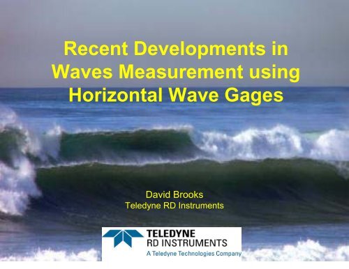
Recent Developments inWaves Measurement usingHorizontal Wave GagesDavid BrooksTeledyne RD Instruments
TALK OUTLINE1. Introduction – about me.2. About Teledyne RD Instruments3. Overview of Waves and H-Waves4. Benefits of H-ADCP as a Wave Gage5. Wide-Band vs. Narrow-Band Broadband6. Depth Considerations7. <strong>Directional</strong> <strong>Noise</strong> <strong>Floor</strong>8. Application notes on Hyberbolic Trig Functions9. Future Areas for Development10. Questions
INTRODUCTION
INTRODUCTION• David Brooks, from Teledyne RD Instruments.• Lead Software Engineer on WavesMon.• Email: dbrooks@teledyne.com• Phone: (858)842-2766• B.S. in Physics, SUNY Stony Brook• 20+ years professional programming experience.Specialization in 3D Graphics.• Principal researchers: Brandon Strong and Blair Brumley.• I am a programmer, not an Oceanographer – so go easy onme ☺
TELEDYNE RD INSTRUMENTS
TELEDYNE RD INSTRUMENTS• Founded in 1981 as RD Instruments• Purchased in 2005 by Teledyne• TRDI Facility: San Diego, California• International offices: France, China• 200+ staff• 10,000+ ADCP’s sold! Huge mark for the world of ADCP’s.• ISO9001-2000 certified. Helps ensure that our products areproperly QC’d, and our processes are continuallyimproving.• Dedicated Waves Program in place since 90’s. Would liketo grow this program, but we need to grow the businessside as well.
OVERVIEW
OVERVIEW• TRDI has a long-standing development effort in WavesMeasurement, including patented waves algorithms for bothVertical and Horizontal systems.• Original development was on Vertical systems in 90’s.• Expanded into H-Waves in 2004.• Teledyne has just gone through a development effort to tweak,tune, and improve our overall Horizontal Waves Processingpackage based on several years of data and analysis.• I wanted to present some of our findings here, along with thebenefits of H-ADCP’s.(chart on ADCP vs. H-ADCP…)
OVERVIEW
H-ADCP Wave Gages Benefits
H-ADCP Wave Gages Benefits• Deploying instruments on the ocean floor can beproblematic.• Where real-time feedback is needed your currentoptions are Fixed Cable, NEMO, Radar, Buoy, etc.• Fixed Cable has issues in that the ocean floor isshifting while the PC is not. This leads to chafing,stretching, and breaking of cable. Cable isexpensive to purchase, install, and replace.• NEMO helps, but is limited by battery lifetime, andneeds recovery.
H-ADCP Wave Gages Benefits• Mounting an HADCP to a platform or pier, is easier tomaintain, has no separation issues, and limitedchafing issues if installed properly.• For off-shore applications (rigs, drill-ships, containerbuoy's, etc) vertical ADCP is not an option, andsingle-point techniques are difficult or impossible.• H-ADCP measures currents, temperature, salinity aswell – a big plus for some customers.• Recent Legislation on Oil Platforms.
Wide-Band vs. Narrow-BandBroadband
Wideband vs. Narrowband• When H-ADCP was created it was desired to extendthe profiling range as far from the measurementplatform as possible. This way the impacts of theplatform could be minimized.• Consider a center-core Drill Rig with an ADCPmounted on the core. We don’t want to bemeasuring currents as they flow around the core,rather we want to be measuring what they would bein the absence of the Rig.• The same goes for Waves. We want to stay out ofthe “shadow” of the platform.
Wideband vs. Narrowband• Our ADCP’s have two Broadband Modes.• Wide-Band Broadband (WB0)– Data has a lower variance – measurement is “quieter”– Lower profiling range• Narrow-Band Broadband (WB1)– Data has a higher variance – measurement is more noisy– Higher profiling range– (Still Broadband though)(see next chart…)
Wideband vs. Narrowband
Wideband vs. Narrowband• By using narrowband mode (WB1) we extend the profilingrange by about 25%. (still Broadband though)• This is the default for H-ADCP’s (vs. Wideband mode forVertical ADCP’s).• Waves Software was not explicitly programming H-ADCP’s forWideband mode, resulting in measurements that were muchmore noisy than Wideband.• This is detrimental to the array approach which is looking forphase coherency. When the signal is buried in the noise it ismuch harder to find using Array Processing.• WHAT WE CHANGED: We always program H-ADCP’s forWideband Mode!! What we give up in range can usually bemade up for by strategically positioning the instrument.• This was a nice piece of the puzzle!
Depth Considerations
Depth Considerations• Wave energy attenuates exponentially with depth.• The array approach requires orbital velocity sensormeasurements to be translated to the surface.• A velocity measurement includes both Signal and <strong>Noise</strong>. Whenwe translate the measurements we translate the signal AND thenoise. As the S/N ratio drops more noise is showing up in thehigher frequencies of the spectrum.• Because of this we need an automated way of obtaining anupper cutoff frequency based on depth of measurement.• For vertical systems this is less of an issue because ourmeasurement is close to the surface. For Horizontal systemsour measurement is typically at instrument depth which can beanywhere from 5-30 meters (or more).
Depth ConsiderationsFrequency Decay With DepthMiMinimum MeasurableWave Period (sec)16.014.012.010.08.06.04.02.00.05.0 10.0 20.0 40.0 80.0 120.0Depth (m)<strong>Directional</strong> (array)Non-<strong>Directional</strong> (pressure)Non <strong>Directional</strong> (velocity)Surface Tracking
Depth Considerations• WHAT WE CHANGED:• Mount the instrument as shallow as possible so thatit is always submerged (and then some to accountfor beam dispersion and the maximum wave troughyou expect to encounter).• If you need to mount deep then try pointing thebeams slightly up so you get higher in the watercolumn towards the end of your profiling range.• We automated our upper cut-off frequencycalculation.
<strong>Directional</strong> <strong>Noise</strong> <strong>Floor</strong>
<strong>Directional</strong> <strong>Noise</strong> <strong>Floor</strong>• Horizontal Wave Gages can only measurethe component of the orbital velocities thatare projected down the beam.• If wave energy is propagatingperpendicular to the beam then very littlevelocity is projected down the beam andhence very little of the wave is measured.• At the same time the noise is isotropic –evenly spread over all directions.
<strong>Directional</strong> <strong>Noise</strong> <strong>Floor</strong>• The anisotropic signal mixed with isotropicnoise results in a directionally dependantS/N ratio.• In our worst case scenario, theconsequences of waves coming from theside is a S/N ratio that is approximately 12times worse than it would be if the wavesarrived straight on.
0.040.0350.030.0250.020.0150.010.0050<strong>Directional</strong> <strong>Noise</strong> <strong>Floor</strong><strong>Directional</strong> <strong>Noise</strong> <strong>Floor</strong>H-ADCP <strong>Directional</strong> <strong>Noise</strong> <strong>Floor</strong>1224364860728496108120132144156168180192204216228240252264276288300312324336348Angle<strong>Noise</strong> <strong>Floor</strong>0Power (Normalized)
<strong>Directional</strong> <strong>Noise</strong> <strong>Floor</strong>• We use the Maximum Likelihood Method(MLM) to determine directional spectra.• This method essentially looks for wherewaves aren’t to quantify where they are.• With an isotropic noise floor we can getmisleading directional spectra.
0.040.0350.030.0250.020.0150.010.0050<strong>Directional</strong> <strong>Noise</strong> <strong>Floor</strong><strong>Directional</strong> <strong>Noise</strong> <strong>Floor</strong><strong>Directional</strong> Spectrum <strong>Noise</strong> <strong>Floor</strong>020406080100120140160180200220240260280300320340DirectionEnergy (Normalized)
<strong>Directional</strong> <strong>Noise</strong> <strong>Floor</strong>• Since we scale our directional spectra byour non-directional spectra we only runinto problems when there is measurable(but not dominating the noise) nondirectionalenergy.• This is when we see noise floor “wings”.
<strong>Directional</strong> <strong>Noise</strong> <strong>Floor</strong>
<strong>Directional</strong> <strong>Noise</strong> <strong>Floor</strong>• If the energy in the non-directional spectraat a given frequency band is large enoughthen it can be the case that this frequencyband is picked as the peak. In this case,unless the wave energy dominates thenwe will pick the noise floor “wings”.• This can result in a miscalled Dp.
<strong>Directional</strong> <strong>Noise</strong> <strong>Floor</strong>
<strong>Directional</strong> <strong>Noise</strong> <strong>Floor</strong>• WHAT WE CHANGED:• When possible try to mount the H-ADCPso that it points into the wave energy. Forinstance if you are mounting it to a pierhave it face the ocean, not the beach.• Employ a directional noise floor squelchingalgorithm [see below].
<strong>Noise</strong> <strong>Floor</strong> Squelch• The high-level approach is simple. Wesubtract the theoretical noise floor from thedirectional spectra, and are left with thedirectional spectra from the signal only.
3483360.040.0350.030.0250.020.0150.010.0050<strong>Noise</strong> <strong>Floor</strong> SquelchH-ADCP <strong>Directional</strong> <strong>Noise</strong> <strong>Floor</strong>3241224364860728496108120132144156168180192204216228240252264276288300312Angle<strong>Noise</strong> <strong>Floor</strong>0Power (Normalized)
<strong>Noise</strong> <strong>Floor</strong> Squelch• We employ screening criterion to makesure that only signal that is greater thanthe noise floor by a certain factor is left.
3523363203040.040.0350.030.0250.020.0150.010.0050<strong>Noise</strong> <strong>Floor</strong> SquelchH-ADCP <strong>Noise</strong> <strong>Floor</strong> SquelchingOriginal <strong>Noise</strong> <strong>Floor</strong> Output-Clamped288648096112128144160176192208224240256272Direction4832160Power - Normalized
<strong>Noise</strong> <strong>Floor</strong> Squelch• After analyzing results from a number of data setswe discovered that the noise floor was not alwaysshowing up where we expected it to be.• Sometimes it would be shifted by as much as 20degrees.• It turns out that the noise floor is also dependant oninstrument roll.• So we have to model this as well, based oninstrument roll before we subtract it out.
126121116120100806040200<strong>Noise</strong> <strong>Floor</strong> SquelchRolled H-ADCP <strong>Noise</strong> <strong>Floor</strong>16111621263136414651566166717681869196101106111Frequency BandDirection
Usage Notes on sinh()/()/cosh()
Usage notes on sinh()/()/cosh()• When we started to deploy instruments indeep water we discovered that the wavesalgorithm was slowing down significantly(exponentially) with depth.• After some investigation we discoveredthat the slow-down was related to thetranslation of horizontal and verticalcomponents of orbital velocity to surfacedisplacement.
Usage notes on sinh()/()/cosh()• The equations in use are of this form:F = cosh(k(h+z))/sinh(kh)• When h gets large the numerator anddenominator can be on the order of 10 250 ,or greater (or even NaN or Infinity)• What we are after – the ratio of the two,may have a small value – such as 20.
Usage notes on sinh()/()/cosh()• The solution is to express the sinh() andcosh() as exponentials using:cosh(x) = (e x + e -x )/2sinh(x) = (e x – e -x )/2• By factoring out terms we are left with:F = (exp(kz) + exp(-2kh - kz))/(1 - exp(-2kh))
Usage notes on sinh()/()/cosh()• We are using the standard c++ double precisionfloating-point libraries and Microsoft VS-2005.• It appears that the exp() routine is more robustthan the sinh() and cosh() routines. It convergesto a solution much more quickly.• If you are using the hyperbolic trig functions inyour routines – take close note to the magnitudeof the arguments passed!!
Future areas of Development
Future areas of Development• More automated Software Solutions – industrial applicationsare looking for highly automated, consolidated reporting ofoceanographic parameters.– Dp, Hs, Tp– Navy Sea-state: 1-10• Better handling of platform motion.• We would like to be able to measure waves and currents from amoving boat eventually.• Exporting Fourier Coefficients for Cross-Comparison.• Sea and Swell Identification.• Let us know what you are looking for.
Conclusions
Conclusions• H-ADCP’s can be used from a wide array ofmeasurement platforms.• Many of these platforms represent unique mountingopportunities to H-ADCP such as Ships, Rigs,Container Buoy's, etc.• H-ADCP’s record current information as well ascalculating Wave Parameters, temperature, salinity,HPR, etc…
Conclusions• We have to take care with H-ADCP since it by defaultmeasures in Narrow-Band Broadband Mode. Thenew WavesMon addresses this.• We want to mount H-ADCP’s as close to the surfaceas possible, and pointed slightly up (2-5 degrees).• Because of the beam geometry there is an inherentlyisotropic S/N ratio. This is accounted for in the newWavesMon.• Take care of the magnitude of the arguments whenusing Hyperbolic Trig. functions, as you canexperience significant slow-down when >50.
THANK YOU!• Thank You for having me at ScrippsInstitute to talk about H-Waves!!• David Brooks, from Teledyne RDInstruments.• Email: dbrooks@teledyne.com• Phone: (858)842-2766• Questions?