Sym Orbit service manual - Scootergrisen
Sym Orbit service manual - Scootergrisen
Sym Orbit service manual - Scootergrisen

Create successful ePaper yourself
Turn your PDF publications into a flip-book with our unique Google optimized e-Paper software.
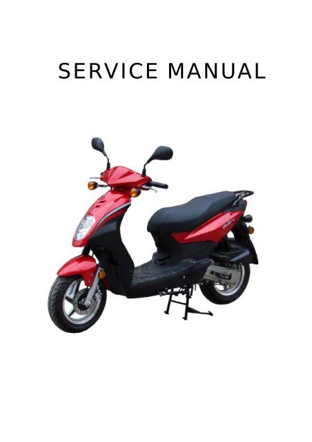
SERVICE MANUAL
HOW TO USE THIS MANUAL SYM<br />
This <strong>service</strong> <strong>manual</strong> describes basic information of different system parts and<br />
system inspection & <strong>service</strong> for SYM series motorcycles. In addition, please<br />
refer to the <strong>manual</strong> contents in detailed for the model you <strong>service</strong>d in<br />
inspection and adjustment.<br />
The first chapter covers general information and trouble diagnosis.<br />
The second chapter covers <strong>service</strong> maintenance.<br />
The third to the eleventh chapters cover engine and driving systems.<br />
The twelfth to fifteenth chapters are contained the parts set of assembly<br />
body.<br />
The sixteenth chapter is electrical equipment.<br />
The seventh chapter is for wiring diagram.<br />
Please see index of content for quick having the special parts and system<br />
information.
SYM CONTENTS<br />
CONTENTS<br />
GENERAL INFORMATION/TROUBLE DIAGNOSIS ...................................1<br />
MAINTENANCE INFORMATION .................................................................2<br />
LUBRICATION SYSTEM..............................................................................3<br />
FUEL SYSTEM .............................................................................................4<br />
ENGINE REMOVAL......................................................................................5<br />
CYLINDER HEAD/VALVE............................................................................6<br />
CYLINDER/PISTON......................................................................................7<br />
"V" TYPE BELT DRIVING SYSTEM/KICK STARTER ARM .......................8<br />
FINAL DRIVING MECHANISM.....................................................................9<br />
A.C. GENERATOR/STARTING CLUTCH ....................................................10<br />
CRANKCASE/CRANKSHAFT .....................................................................11<br />
BODY COVER ..............................................................................................12<br />
BRAKE SYSTEM..........................................................................................13<br />
STEERING/FRONT WHEEL/FRONT SHOCK ABSORBER........................14<br />
REAR WHEEL/SUSPENSION......................................................................15<br />
ELECTRICAL EQUIPMENT .........................................................................16<br />
ELECTRICAL DIAGRAM .............................................................................17
MECHANISM ILLUSTRATIONS SYM<br />
Rear brake lever<br />
Front turn<br />
signal light Fuel tank / Fuel unit<br />
Head light/<br />
Position light<br />
Front disk brake<br />
Rear turn<br />
signal light<br />
Exhaust muffler<br />
Ignition coil<br />
Oil level<br />
Meter<br />
Horn/REG.REC<br />
Engine control<br />
switch<br />
Tail light<br />
Light/starter switch<br />
Frame number<br />
High&Low beam/Seat<br />
open/turn signal/horn<br />
Tail light<br />
Air cleaner<br />
Gear oil filling<br />
bolt<br />
Gear oil draining<br />
bolt<br />
Engine number/engine<br />
oil draining bolt<br />
Battery/Fuse/CDI Front brake lever<br />
A.C. Generator<br />
Start magnetic switch<br />
RR. turning<br />
signal light<br />
Winker relay<br />
Front turn<br />
signal light<br />
Ignition switch
SYM 1. GENERAL INFORMATION/TROUBLE DIAGNOSIS<br />
SYMBOLS AND MARKS ....................1-1<br />
GENERAL SAFETY............................1-2<br />
SERVICE PRECAUTIONS .................1-3<br />
SPECIFICATIONS..............................1-9<br />
SYMBOLS AND MARKS<br />
TORQUE VALUES (ENGINE).............. 1-10<br />
TORQUE VALUES (FRAME) ............... 1-11<br />
TROUBLES DIAGNOSIS ..................... 1-12<br />
LUBRICATION POINTS ....................... 1-16<br />
<strong>Sym</strong>bols and marks are used in this <strong>manual</strong> to indicate what and where the special <strong>service</strong> are<br />
needed, in case supplemental information is procedures needed for these symbols and marks,<br />
explanations will be added to the text instead of using the symbols or marks.<br />
Warning<br />
Caution<br />
Engine oil<br />
Grease<br />
Locking sealant<br />
Renew<br />
Oil seal<br />
Special tools<br />
Brake fluid<br />
Correct<br />
Wrong<br />
Means that serious injury or even death may result if procedures are not<br />
followed.<br />
Means that equipment damages may result if procedures are not followed.<br />
Limits to use SAE 10W-30 API SH/CD class oil. Warranty will not cover the<br />
damage that caused by not apply with the limited engine oil.<br />
King Mate G-3 is recommended.<br />
Apply sealant, medium strength sealant should be used unless otherwise<br />
specified.<br />
Apply with lubricant.<br />
Replace with a new part before installation.<br />
Use recommended brake fluid DOT3 or WELLRUN brake fluid.<br />
Special <strong>service</strong> tools.<br />
Meaning correct installation.<br />
Meaning wrong installation.<br />
Indication Indication of components.<br />
Directions<br />
Indicates position and operation directions.<br />
Components assembly directions each other.<br />
Indicates where the bolt installation direction, --- means that bolt cross<br />
through the component (invisibility).<br />
1-1
1. GENERAL INFORMATION/TROUBLE DIAGNOSIS SYM<br />
GENERAL SAFETY<br />
Carbon monoxide<br />
If you must run your engine, ensure the place is<br />
well ventilated. Never run your engine in a<br />
closed area. Run your engine in an open area, if<br />
you have to run your engine in a closed area, be<br />
sure to use an extractor.<br />
Caution<br />
Exhaust contains toxic gas which may cause<br />
one to lose consciousness and even result in<br />
death.<br />
Gasoline<br />
Gasoline is a low ignition point and explosive<br />
material. Work in a well-ventilated place, no<br />
flame or spark should be allowed in the work<br />
place or where gasoline is being stored.<br />
Caution<br />
Gasoline is highly flammable, and may explode<br />
under some conditions, keep it away from<br />
children.<br />
Used engine oil<br />
Caution<br />
Prolonged contact with used engine oil (or<br />
transmission oil) may cause skin cancer<br />
although it might not be verdict.<br />
Hot components<br />
Caution<br />
Components of the engine and exhaust system<br />
can become extremely hot after engine running.<br />
They remain very hot even after the engine has<br />
been stopped for some time. When performing<br />
<strong>service</strong> work on these parts, wear insulated<br />
gloves and wait until cooling off.<br />
1-2<br />
Battery<br />
Caution<br />
� Battery emits explosive gases; flame is<br />
strictly prohibited. Keep the place well<br />
ventilated when charging the battery.<br />
� Battery contains sulfuric acid (electrolyte)<br />
which can cause serious burns so be careful<br />
do not be spray on your eyes or skin. If you<br />
get battery acid on your skin, flush it off<br />
immediately with water. If you get battery<br />
acid in your eyes, flush it off immediately<br />
with water, then go to hospital to see an<br />
ophthalmologist.<br />
� If you swallow it by mistake, drink a lot of<br />
water or milk, and take some laxative such<br />
as castor oil or vegetable oil, and then go to<br />
see a doctor.<br />
� Keep electrolyte beyond reach of children.<br />
Brake shoe<br />
Do not use an compressed air or a dry brush to<br />
clean components of the brake system, use a<br />
vacuum cleaner or the equivalent to avoid<br />
asbestos dust flying.<br />
Caution<br />
Inhaling asbestos dust may cause disorders<br />
and cancer of the breathing system.<br />
Brake fluid<br />
Caution<br />
Spilling brake fluid on painted, plastic, or rubber<br />
parts may cause damage to the parts. Place a<br />
clean towel on the above-mentioned parts for<br />
protection when servicing the brake system.<br />
Keep brake fluid beyond reach of children.
SYM 1. GENERAL INFORMATION/TROUBLE DIAGNOSIS<br />
SERVICE PRECAUTIONS<br />
� Always use with SANYANG genuine parts<br />
and recommended oils. Using non-designed<br />
parts for SANYANG motorcycle may damage<br />
the motorcycle.<br />
� Special tools are designed for remove and<br />
install of components without damaging the<br />
parts being worked on. Using wrong tools<br />
may result in parts damaged.<br />
� When servicing this motorcycle, use only<br />
metric tools. Metric bolts, nuts, and screws<br />
are not interchangeable with the English<br />
system, using wrong tools and fasteners may<br />
damage this vehicle.<br />
� Clean the outside of the parts or the cover<br />
before removing it from the motorcycle.<br />
Otherwise, dirt and deposit accumulated on<br />
the part's surface may fall into the engine,<br />
chassis, or brake system to cause a damage.<br />
� Wash and clean parts with high ignition point<br />
solvent, and blow dry with compressed air.<br />
Pay special attention to O-rings or oil seals<br />
because most cleaning agents have an<br />
adverse effect on them.<br />
� Never bend or twist a control cable to prevent<br />
stiff control and premature worn out.<br />
� Rubber parts may become deteriorated when<br />
old, and prone to be damaged by solvent and<br />
oil. Check these parts before installation to<br />
make sure that they are in good condition,<br />
replace if necessary.<br />
� When loosening a component which has<br />
different sized fasteners, operate with a<br />
diagonal pattern and work from inside out.<br />
Loosen the small fasteners first. If the bigger<br />
ones are loosen first, small fasteners may<br />
receive too much stress.<br />
� Store complex components such as<br />
transmission parts in the proper assemble<br />
order and tie them together with a wire for<br />
ease of installation later.<br />
� Note the reassemble position of the important<br />
components before disassembling them to<br />
ensure they will be reassembled in correct<br />
dimensions (depth, distance or position).<br />
� Components not to be reused should be<br />
replaced when disassembled including<br />
gaskets metal seal rings, O-rings, oil seals,<br />
snap rings, and split pins.<br />
1-3
1. GENERAL INFORMATION/TROUBLE DIAGNOSIS SYM<br />
� The length of bolts and screws for<br />
assemblies, cover plates or boxes is different<br />
from one another, be sure they are correctly<br />
installed. In case of confusion, Insert the bolt<br />
into the hole to compare its length with other<br />
bolts, if its length out side the hole is the<br />
same with other bolts, it is a correct bolt.<br />
Bolts for the same assembly should have the<br />
same length.<br />
� Tighten assemblies with different dimension<br />
fasteners as follows:<br />
� Tighten all the fasteners with fingers, then<br />
tighten the big ones with special tool first<br />
diagonally from inside toward outside,<br />
important components should be tightened 2<br />
to 3 times with appropriate increments to<br />
avoid warp unless otherwise indicated. Bolts<br />
and fasteners should be kept clean and dry.<br />
Do not apply oil to the threads.<br />
� When oil seal is installed, fill the groove with<br />
grease, install the oil seal with the name of<br />
the manufacturer facing outside, check the<br />
shaft on which the oil seal is to be installed<br />
for smoothness and for burrs that may<br />
damage the oil seal.<br />
Manufacturer's<br />
name<br />
1-4<br />
� Remove residues of the old gasket or sealant<br />
before reinstallation, grind with a grindstone if<br />
the contact surface has any damage.<br />
� The ends of rubber hoses (for fuel, vacuum,<br />
or coolant) should be pushed as far as they<br />
can go to their connections so that there is<br />
enough room below the enlarged ends for<br />
tightening the clamps.<br />
Groove<br />
Clamp<br />
Connector<br />
� Rubber and plastic boots should be properly<br />
reinstalled to the original correct positions as<br />
designed.<br />
Boots<br />
� The tool should be pressed against two (inner<br />
and outer) bearing races when removing a<br />
ball bearing. Damage may result if the tool is<br />
pressed against only one race (either inner<br />
race or outer race). In this case, the bearing<br />
should be replaced. To avoid damaging the<br />
bearing, use equal force on both races.<br />
Both of these examples can result in bearing damage.
SYM 1. GENERAL INFORMATION/TROUBLE DIAGNOSIS<br />
� Lubricate the rotation face with specified<br />
lubricant on the lubrication points before<br />
assembling.<br />
� Check if positions and operation for installed<br />
parts is in correct and properly.<br />
� Make sure <strong>service</strong> safety each other when<br />
conducting by two persons.<br />
� Note that do not let parts fall down<br />
� Before battery removal operation, it has to<br />
remove the battery negative (-) cable firstly.<br />
Notre tools like open-end wrench do not<br />
contact with body to prevent from circuit short<br />
and create spark.<br />
� After <strong>service</strong> completed, make sure all<br />
connection points is secured. Battery<br />
positive (+) cable should be connected firstly.<br />
And the two posts of battery have to be<br />
greased after connected the cables.<br />
� Make sure that the battery post caps are<br />
located in properly after the battery posts had<br />
been <strong>service</strong>d.<br />
� If fuse burned, it has to find out the cause<br />
and solved it. And then replace with<br />
specified capacity fuse.<br />
capacity<br />
verification<br />
1-5
1. GENERAL INFORMATION/TROUBLE DIAGNOSIS SYM<br />
� When separating a connector, it locker has to<br />
be unlocked firstly. Then, conduct the<br />
<strong>service</strong> operation.<br />
� Do not pull the wires as removing a<br />
connector or wires. Hold the connector<br />
body.<br />
� Make sure if the connector pins are bent,<br />
extruded or loosen.<br />
� Insert the connector completely. If there are<br />
two lockers on two connector sides, make<br />
sure the lockers are locked in properly.<br />
Check if any wire loose.<br />
� Check if the connector is covered by the twin<br />
connector boot completely and secured<br />
properly.<br />
1-6<br />
� Before terminal connection, check if the boot<br />
is crack or the terminal is loose.<br />
� Insert the terminal completely. Check if the<br />
terminal is covered by the boot. Do not let<br />
boot open facing up.<br />
� Secure wires and wire harnesses to the<br />
frame with respective wire bands at the<br />
designated locations. Tighten the bands so<br />
that only the insulated surfaces contact the<br />
wires or wire harnesses.<br />
� Wire band and wire harness have to be<br />
clamped secured properly.<br />
� Do not squeeze wires against the weld or its<br />
clamp.
SYM 1. GENERAL INFORMATION/TROUBLE DIAGNOSIS<br />
� Do not let the wire harness contact with<br />
rotating, moving or vibrating components as<br />
routing the harness.<br />
� Keep wire harnesses far away from the hot<br />
parts.<br />
� Route wire harness to avoid sharp edges or<br />
corners and also avoid the projected ends of<br />
bolts and screws.<br />
� Route harnesses so that they neither pull too<br />
tight nor have excessive slack.<br />
Do not extend<br />
it too much.<br />
Do not touch it.<br />
� Protect wires or wire harnesses with electrical<br />
tape or tube if they contact a sharp edge or<br />
corner. Thoroughly clean the surface where<br />
tape is to be applied.<br />
� Secure the rubber boot firmly as applying it<br />
on wire harness.<br />
� Never use wires or harnesses which<br />
insulation has been broken. Wrap electrical<br />
tape around the damaged parts or replace<br />
them.<br />
� Never clamp or squeeze the wire harness as<br />
installing other components.<br />
Please do not clip or<br />
squeeze the wire.<br />
1-7
1. GENERAL INFORMATION/TROUBLE DIAGNOSIS SYM<br />
� Do not let the wire harness been twisted as<br />
installation.<br />
� Wire harnesses routed along the handlebar<br />
should not be pulled too tight or have<br />
excessive slack, be rubbed against or<br />
interfere with adjacent or surrounding parts in<br />
all steering positions.<br />
� Before operating a test instrument, operator<br />
should read the operation <strong>manual</strong> of the<br />
instrument. And then, conduct test in<br />
accordance with the instruction.<br />
1-8<br />
Do you know how to set the<br />
instrument to its measurement<br />
position and the insert locations<br />
of its two probes?<br />
� With sand paper to clean rust on connector<br />
pins/terminals if found. And then conduct<br />
connection operation later.<br />
Clean rust.
1. GENERAL INFORMATION/TROUBLE DIAGNOSIS SYM<br />
TORQUE VALUES (ENGINE)<br />
1-10<br />
ITEM Q'TY<br />
THREAD DIA<br />
(mm)<br />
TORQUE<br />
VALUE(Kg-m)<br />
Cylinder head bolts 4 6 0.8~1.2<br />
REMARKS<br />
Cylinder head nuts 4 8 1.8~2.2 Apply oil to thread<br />
Cylinder/cylinder head two-ends bolts 4 7 0.7~1.1 Tighten to crankcase<br />
Cam holder nut 4 7 0.8~1.2<br />
Right crank case cover bolts 10 6 0.8~1.2<br />
Pulse generator bolts 2 5 0.35~0.5<br />
Valve adjustment fixing nuts 2 6 0.7~1.1 Apply oil to thread<br />
Spark plug 1 10 1.0~1.4<br />
Engine oil strainer cap 1 30 1.0~2.0<br />
Gear oil draining plug 1 10 1.0~1.4<br />
Gear oil filling bolt 1 10 1.0~1.5<br />
Oil pump bolts 3 6 0.8~1.2<br />
Oil pump drive sprocket nuts 1 6 0.8~1.2<br />
Left crankcase cover bolts 10 6 0.8~1.2<br />
Cylinder head cover bolts 4 6 0.8~1.2<br />
Camshaft chain tensioner pivot 1 6 0.8~1.2 Hex socket bolt<br />
Camshaft chain adjuster bolts 2 6 1.0~1.4<br />
Cooling fan bolts 4 6 0.8~1.2<br />
Shroud A/B 2 6 0.8~1.2<br />
RR. brake fixing nut 1 8 1.5~2.0<br />
Flywheel nut 1 10 3.5~4.5<br />
Transmission(Gear box) bolts 7 8 2.6~3.0<br />
RR. brake arm bolt 1 6 0.7~1.1<br />
Drive face nut 1 12 5.0~6.0<br />
Drive pulley nut 1 10 3.5~4.5<br />
A.C. generator flange bolt 2 6 0.8~1.2<br />
Air/C connect bracket bolts 2 6 0.8~1.2<br />
Start motor bolts 2 6 0.8~1.2<br />
Brake arm bolt 1 6 0.7~1.1<br />
Kick starter arm bolt 1 6 0.8~1.2<br />
Carburetor nut 2 6 0.8~1.2<br />
A.I. fixing hex cap nut 2 6 0.8~1.2<br />
Crankcase bolts 1 6 0.8~1.2<br />
Exhaust pipe bolts 2 8 3.0~3.6<br />
Exhaust pipe connecting nuts 2 6 1.0~1.4
1. GENERAL INFORMATION/TROUBLE DIAGNOSIS SYM<br />
TROUBLES DIAGNOSIS<br />
A. Engine hard to start or can not be started<br />
Check and adjustment Fault condition Probable causes<br />
Loosen carburetor drain<br />
bolt to check if there is<br />
gasoline inside the<br />
carburetor<br />
1-12<br />
Fuel supplied tom<br />
carburetor sufficient<br />
Remove spark plug, install<br />
it into spark plug cap, and<br />
perform a spark test<br />
against engine ground.<br />
perform cylinder<br />
compression pressure test.<br />
No fuel is supplied to<br />
carburetor<br />
Check if sparks Weak sparks, no spark<br />
at all<br />
cylinder compression<br />
pressure normal<br />
Re-start by following the<br />
starting procedures<br />
Low compression<br />
pressure or no pressure<br />
No ignition There are some signs of<br />
ignition, nut engine can<br />
not be started<br />
Remove the spark plug<br />
again and check it.<br />
Dry spark plug<br />
Remove carburetor after 30 minutes<br />
and connect a hose onto fuel rich<br />
circuit. Then blow the hose with air<br />
Wet spark plug<br />
Blowing in normal Blowing clogged<br />
1. No fuel in fuel tank<br />
2. Check if the pipes, fuel tank to<br />
carburetor and intake vacuum,<br />
are clogged.<br />
3. Float valve clogged<br />
4. Lines in fuel tank evaporation<br />
system clogged<br />
5. Malfunction of fuel pump<br />
6. Loosen or damaged fuel pump<br />
vacuum hose<br />
7. Fuel filter clogged<br />
1. Malfunction of spark plug<br />
2. Spark plug foul<br />
3. Malfunction of CDI set<br />
4. Malfunction of AC generator<br />
5. Ignition coil is in open or short<br />
circuit<br />
6. Ignition coil leads open or short<br />
circuit<br />
7. Malfunction of main switch<br />
1. Piston ring seized<br />
2. Malfunction of cylinder valves<br />
3. Worn cylinder and piston ring<br />
4. Cylinder gasket leak<br />
5. Sand hole in compression parts<br />
1. Malfunction of throttle valve<br />
operation<br />
2. Air sucked into intake manifold<br />
3. Incorrect ignition timing<br />
1. Fuel level in carburetor too high<br />
2. Malfunction of throttle valve<br />
operation<br />
3. Throttle valve opening too wide<br />
1. Malfunction of automatic by-<br />
starter
SYM 1. GENERAL INFORMATION/TROUBLE DIAGNOSIS<br />
E. CLUTCH, DRIVING AND DRIVING PULLEY<br />
FAULT CONDITIONS PROBABLE CAUSES<br />
Engine can be started but<br />
motorcycle can not be moved.<br />
Engine running and misfire as<br />
motorcycle initial forward moving<br />
or jumping suddenly (rear wheel<br />
rotating as engine in running)<br />
Poor initial driving ( Poor climbing<br />
performance)<br />
1. Driving belt worn out or deformation<br />
2. Driving disk damaged<br />
3. Driving pulley spring broken<br />
4. Clutch ling broken<br />
5. Driving slide-shaft gear groove broken<br />
6. Transmission gear damaged<br />
1. Clutch ling spring broken<br />
2. Clutch outer stick with clutch balance weights<br />
3. Connection parts in clutch and shaft worn out<br />
or burned<br />
1. Driving belt worn out or deformation<br />
2. Balance weight roller worn out<br />
3. Driving sliding gear shaft worn out<br />
4. Driving disk spring deformation<br />
5. Driving sliding gear shaft worn out<br />
6. Greased in driving belt and sliding gear.<br />
1-15
1. GENERAL INFORMATION/TROUBLE DIAGNOSIS SYM<br />
LUBRICATION POINTS<br />
1-16<br />
Steering shaft bearing<br />
Speedometer gear /<br />
Front wheel bearing<br />
Acceleration cable/ Front & rear brake lever pivot<br />
Side stand shaft<br />
Main stand shaft<br />
Seat lock<br />
Rear wheel bearing
SYM 2. MAINTENANCE INFORMATION<br />
LUBRICATION SYSTEM<br />
Engine Oil Capacity<br />
Caution<br />
� The vehicle must be parked on a level<br />
ground when checking oil capacity.<br />
� Run the engine for 2-3 minutes then stop,<br />
wait about 2-3 more minutes allowing<br />
engine oil to settle before checking the oil<br />
level.<br />
Remove dipstick to check the oil level. If oil<br />
level is below the lower limit mark, add oil to<br />
the specified upper limit mark.<br />
Oil change<br />
Shut off the engine and remove dipstick.<br />
Remove the oil drain plug on the bottom-left<br />
of crankcase to drain oil.<br />
After draining out oil, clean oil plug and its<br />
+-gasket and reinstall. Replace the gasket if<br />
it is damaged.<br />
Torque value1.0~1.5 kgf-m<br />
Caution<br />
Warm up the engine. This will make the oil<br />
flow out easily.<br />
Add oil to the specified capacity.<br />
Oil Viscosity: SAE 10W-30, recommended<br />
using King-Mate serial oil.<br />
Engine oil capacity:<br />
Disassembly: 850cc<br />
Change: 750cc<br />
When checking for oil leak, run the engine at<br />
idle speed for a few minutes, then check oil<br />
capacity with dipstick.<br />
Cleaning the oil strainer<br />
Drain oil from engine, remove the strainer<br />
cover, spring and strainer.<br />
If there is an accumulation on the screen,<br />
wash it off with suitable solvent<br />
(recommended using compressed air).<br />
Check O-ring for damage, replace if<br />
necessary.<br />
Reinstall strainer, spring, O-ring and strainer<br />
cover.<br />
Torque value: 1.0~2.0 kgf-m<br />
Dipstick<br />
Oil drain plug<br />
strainer cover<br />
oil strainer<br />
spring<br />
2-3
2. MAINTENANCE INFORMATION SYM<br />
Gear Oil<br />
Inspection<br />
Check gear oil if leaking.<br />
Park the motorcycle with main stand on flat<br />
level place.<br />
Turn off engine and remove the gear oil<br />
draining plug.<br />
Place a measurement cup under the draining<br />
hole.<br />
Remove the oil drain plug and drain gear oil<br />
into a measurement cup.<br />
Check gear oil if enough.<br />
Replacement<br />
At first, remove the gear oil refilling bolt, and<br />
then remove the draining plug.<br />
Install the draining plug after drained oil out.<br />
Torque value: 1.0~1.5 kgf-m<br />
Caution<br />
Inspect if washer is in good condition.<br />
Replace it with new one if it was deformed<br />
or damaged.<br />
Fill out gear oil to specified quantity from the<br />
engine oil filling hole.<br />
Install the oil filling bolt.<br />
Torque value: 1.0~1.5 kgf-m<br />
Quantity: 90 c.c.<br />
Recommended: King-Mate HYPOID GEAR<br />
OIL ( #140 ).<br />
Fuel System<br />
Fuel Pipe<br />
Remove luggage box, rear center cover,<br />
body cover, and rear fender, as well as front<br />
inner box.<br />
Check all pipes, and replace it when they are<br />
deterioration, damage or leaking.<br />
Warning<br />
Gasoline is a low ignition material so any<br />
kind of fire is strictly prohibited as dealing<br />
it.<br />
Fuel filter<br />
Remove the fuel tank.<br />
Remove fuel pipe from the fuel filter.<br />
Replace the fuel filter with new one.<br />
Install the fuel filter.<br />
Caution<br />
The arrow on the fuel filter means the flow<br />
direction of fuel and check it if leaking after<br />
installation.<br />
2-4<br />
Gear oil refilling bolt<br />
Fuel filter<br />
Gear oil draining plug
2. MAINTENANCE INFORMATION SYM<br />
IGNITION SYSTEM<br />
Ignition timing<br />
Caution<br />
C.D.I ignition system is set by manufacturer<br />
so it can not be adjusted.<br />
Ignition timing check procedure is for<br />
checking whether C.D.I. function is in normal<br />
or not.<br />
Remove ignition timing hole cap located on<br />
the cooling fan cap, or remove the cooling<br />
fan cap.<br />
Check ignition timing with ignition light.<br />
Start engine and set engine idle speed in<br />
1700 rpm, and if the mark aligns with the “F”,<br />
then it means that ignition timing is correct.<br />
Increase engine speed to 8000 rpm to check<br />
ignition timing advance. If the detent aligns<br />
with advance mark “װ”, then it means ignition<br />
timing advance is in functional. If not,<br />
check CDI set, pulse flywheel, and pulse<br />
generator. Replace these components if<br />
malfunction of these parts are found.<br />
SPARK PLUG<br />
Appointed spark plug: TORCH A7RC<br />
Remove luggage box.<br />
Remove center cover.<br />
Remove spark plug cap.<br />
Clean dirt around the spark plug hole.<br />
Remove spark plug.<br />
Measure spark plug gap.<br />
Spark plug gap: 0.6~0.7 mm<br />
Carefully bend ground electrode of the plug<br />
to adjust the gap if necessary.<br />
Screw the park plug into the plug hole with<br />
hands, then tighten the plug with a wrench to<br />
prevent from damaging the spark plug's<br />
thread.<br />
Torque value: 1.0~1.4 kgf-m<br />
Connect spark plug cap.<br />
2-8<br />
Ignition light<br />
Spark plug<br />
Side electrode<br />
0.6~0.7mm<br />
F mark<br />
Center electrode
SYM 2. MAINTENANCE INFORMATION<br />
CYLINDER COPMRESSION PRESSURE<br />
Warn up engine and then turnoff the engine.<br />
Remove the luggage box and the center<br />
cover.<br />
Remove spark plug cap and spark plug.<br />
Install compression gauge.<br />
Full open the throttle valve, and rotate the<br />
engine by means of stepping the<br />
kick-starting lever.<br />
Caution<br />
Rotate the engine until the reading in the<br />
gauge no more increasing.<br />
Usually, the highest pressure reading will be<br />
obtained in 4~7 seconds.<br />
Compression pressure: 12 Kg/cm².<br />
Check following items if the pressure is too<br />
low:<br />
� Incorrect valve clearance<br />
� Valve leaking<br />
� Cylinder head leaking, piston, piston ring<br />
and cylinder worn out<br />
If the pressure is too high, it means carbon<br />
deposits in combustion chamber or piston<br />
head.<br />
DRIVING SYSTEM<br />
DRIVING BELT<br />
Remove left side cover.<br />
Remove mounting bolt located under air<br />
cleaner.<br />
Remove 9 bolts of the engine left crankcase.<br />
Remove the left crankcase cover.<br />
Check if the belt is crack or worn out.<br />
Replace the belt if necessary or in accord<br />
with the periodical maintenance schedule to<br />
replace it.<br />
Width limit: above 18.5 mm<br />
Clutch pad<br />
Start the motorcycle and gradually increase<br />
throttle valve openness to check clutch pad<br />
operation.<br />
If the motorcycle moves with shaking, then<br />
check its clutch pad for wearing. Replace it<br />
if necessary.<br />
Spark plug<br />
Gear teeth<br />
Clutch pad<br />
Width<br />
Cylinder<br />
pressure<br />
gauge<br />
Clutch<br />
2-9
2. MAINTENANCE INFORMATION SYM<br />
STEERING SYSTEM<br />
Caution<br />
Check all wires and cables if they are<br />
interfered with the rotation of steering<br />
handle bar.<br />
Lift the front wheel out of ground.<br />
Turn handle from right to left and check if<br />
turning is smoothly.<br />
If handle turning is uneven and bending, or<br />
the handle can be operated in vertical<br />
direction, then adjust the handle top bearing.<br />
SUSPENSION SYSTEM<br />
Warning<br />
� Do not ride the motorcycle with poor<br />
shock absorber.<br />
� Looseness, wear or damage shock<br />
absorber will make poor stability and<br />
driveability.<br />
Front shock absorber<br />
Hold front brake lever and press down the<br />
front shock absorber for several times to<br />
check its operation.<br />
Hold front brake lever and push forward the<br />
front shock absorber for several times to<br />
check its locking status.<br />
Check if it is scratched or leaking.<br />
Replace damaged and non-repairable<br />
components.<br />
Tighten all nuts and bolts.<br />
Rear Shock absorber<br />
Press down the rear shock absorber for<br />
several times to check its operation.<br />
Check if it is scratched or leaking.<br />
Replace damaged and non-repairable<br />
components.<br />
Park the motorcycle with main standard.<br />
Start engine and let the rear wheel rotate<br />
after increased engine rpm. Check engine<br />
for any parts loose or shaking. Also check<br />
the engine suspension bushing for wear out.<br />
Replace the bushing if worn out.<br />
Tighten all nuts and bolts.<br />
2-10<br />
Rear Shock absorber
SYM 2. MAINTENANCE INFORMATION<br />
FRONT DISC BRAKE SYSTEM<br />
BRAKE SYSTEM HOSE<br />
Make sure the brake hoses for corrosion or<br />
leaking oil, and also check brake system for<br />
leaking.<br />
BRAKE FLUID<br />
Check brake fluid level in the brake fluid<br />
reservoir. If the level is lower than the<br />
LOWER limit, add brake fluid to UPPER limit.<br />
Also check brake system for leaking if low<br />
brake level found.<br />
Caution<br />
� In order to maintain brake fluid in the<br />
reservoir in horizontal position, do not<br />
remove the cap until handle bar stop.<br />
� Do not operate the brake lever after the<br />
cap had been removed. Otherwise, the<br />
brake fluid will spread out if operated the<br />
lever.<br />
� Do not mix non-compatible brake fluid<br />
together.<br />
FILLING OUT BRAKE FLUID<br />
Tighten the drain valve, and add brake fluid.<br />
Place the diaphragm in.<br />
Operate the brake lever so that brake fluid<br />
contents inside the brake system hoses.<br />
AIR BLEED OPERATION<br />
Connect a transparent hose to draining<br />
valve.<br />
Hold the brake lever and open air bleeding<br />
valve. Perform this operation alternative until<br />
there is no air inside the brake system<br />
hoses.<br />
Caution<br />
Before closing the air bleed valve, do not<br />
release the brake lever.<br />
Brake fluid cap<br />
Low brake level<br />
Bubbles<br />
Brake hose<br />
Lower limit<br />
Draining valve<br />
Transparent hose<br />
2-11
2. MAINTENANCE INFORMATION SYM<br />
ADDED BRAKE FLUID<br />
Add brake fluid to UPPER limit lever.<br />
Recommended brake fluid: DOT3 or DOT4<br />
WELL RUN brake fluid.<br />
Caution<br />
Never mix or use dirty brake fluid to prevent<br />
from damage brake system or reducing<br />
brake performance.<br />
BRAKE LINING WEAR<br />
The indent mark on brake lining is the wear<br />
limitation.<br />
Replace the brake lining if the wear limit<br />
mark closed to the edge of brake disc.<br />
Caution<br />
It is not necessary to remove brake hose<br />
when replacing the brake lining.<br />
Remove the brake clipper bolt, and take out<br />
the clipper.<br />
Caution<br />
Do not operate the brake lever after the<br />
clipper removed to avoid clipping the brake<br />
lining.<br />
Pry out the brake lining with a flat driver if<br />
lining be clipped.<br />
Remove brake lining bolt.<br />
Take out the lining.<br />
2-12<br />
Caution<br />
In order to maintain brake power balance,<br />
the brake lining must be replaced with one<br />
set.<br />
Brake fluid cap<br />
Low limit<br />
Brake clipper Brake disc<br />
Brake<br />
clipper bolt<br />
Brake lining<br />
Brake ling wear limit<br />
Bolt
SYM 2. MAINTENANCE INFORMATION<br />
BATTERY<br />
Battery Removal<br />
Remove the 4 screws on the floor panel.<br />
Remove battery cap. (4 screws)<br />
Battery cables removal:<br />
1. At first, remove the negative “-” cable.<br />
2. Then, remove the positive “+” cable.<br />
3. Remove the battery.<br />
If there is some rust on battery posts, clean it<br />
with steel brush.<br />
Install the battery in the reverse procedures<br />
of removal.<br />
Caution<br />
� If there is rust on the posts very serious,<br />
spray some hot water on the posts.<br />
Then, clean it with steel brush so that<br />
can remove rust for more easily.<br />
� Apply some grease on the posts after<br />
rust removed to prevent from rust again.<br />
HEADLIGHT ADJUSTMENT<br />
Remove the front cover.<br />
Turn on the main switch.<br />
Turn the headlight adjustment screw. And<br />
adjust the headlight beam height.<br />
Then, tighten the adjustment screw after the<br />
beam height in proper position.<br />
Caution<br />
� To adjust the headlight beam follows<br />
related regulations.<br />
� Improper headlight beam adjustment will<br />
make in coming driver dazzled or<br />
insufficient lighting.<br />
NUTS, BOLTS TIGHTENESS<br />
Perform periodical maintenance in accord<br />
with the Periodical Maintenance Schedule.<br />
Check if all bolts and nuts on the frame are<br />
tightened securely.<br />
Check all fixing pins, snap rings, hose (pipe)<br />
clamps, and wire holders for security.<br />
Battery cover screws<br />
Headlight adjustment screw<br />
2-15
SYM 3. LUBRICATION SYSTEM<br />
MECHANISM DIAGRAM ....................3-1<br />
OPERATIONAL PRECAUTIONS .......3-2<br />
TROUBLE DIAGNOSIS......................3-2<br />
ENGINE OIL .......................................3-3<br />
MECHANISM DIAGRAM<br />
Valve rocker<br />
arm<br />
Scoop lubrication<br />
Connecting rod<br />
Forcedly<br />
lubrication<br />
Crankshaft<br />
Oil strainer<br />
CLEANING ENGINE OIL STRAINER...3-3<br />
OIL PUMP ............................................3-4<br />
GEAR OIL ............................................3-7<br />
Forcedly lubrication<br />
Camshaft<br />
Oil pump<br />
Inner passage<br />
3-1
3. LUBRICATION SYSTEM SYM<br />
OPERATIONAL PRECAUTIONS<br />
General Information<br />
� This chapter contains maintenance operations for the engine oil pump, engine oil and<br />
gear oil.<br />
Oil viscosity<br />
Specifications<br />
Engine oil quantity Disassembly 850 c.c.<br />
Replacement 750 c.c.<br />
Oil viscosity SAE 10W-30 or equivalent<br />
(Recommended King-Mate<br />
serial oils)<br />
Gear Oil Disassembly 110 c.c.<br />
Replacement 100 c.c.<br />
Oil viscosity of gear oil SAE 85W-140<br />
(Recommended King-Mate<br />
gear oil series SYM<br />
HYPOID GEAR OIL)<br />
3-2<br />
Oil pump<br />
unit : mm<br />
Items Standard Limit<br />
Inner rotor clearance - 0.12<br />
Clearance between outer<br />
rotor and body - 0.12<br />
Clearance between rotor<br />
side and body 0.05~0.10 0.20<br />
Torque value<br />
Engine oil drain plug 1.0~1.5kgf-m<br />
Engine oil screen cover 1.0~2.0kgf-m<br />
Gear oil drain bolt 1.0~1.5kgf-m<br />
Gear oil filling bolt 1.0~1.5kgf-m<br />
Oil pump connection screw 0.8~1.2kgf-m<br />
TROUBLE DIAGNOSIS<br />
Low engine oil level<br />
Oil leaking<br />
Valve guide or seat worn out<br />
Piston ring worn out<br />
Low Oil Pressure<br />
Low engine oil level<br />
Clogged in oil strainer, circuits or pipes<br />
Oil pump damage<br />
Dirty oil<br />
No oil change in periodical<br />
Cylinder head gasket damage<br />
Piston ring worn out
SYM 3. LUBRICATION SYSTEM<br />
ENGINE OIL<br />
Turn off engine, and park the motorcycle in<br />
flat ground with main stand.<br />
Check oil level with oil dipstick after 3-5<br />
minutes.<br />
Do not rotate the dipstick into engine as<br />
checking.<br />
If oil level is nearly low level, fill out<br />
recommended oil to upper level.<br />
Oil Replacement<br />
Caution<br />
Drain oil as engine warmed up so that<br />
make sure oil can be drained smoothly and<br />
completely.<br />
Place an oil pan under the motorcycle, and<br />
remove oil strainer cap.<br />
Make sure if the aluminum washer of the<br />
draining bolt is damaged. If so, replace it<br />
with new one.<br />
Install the drain bolt and tighten it.<br />
Torque value: 3.5~4.5 kgf-m<br />
CLEANING ENGINE OIL STRAINER<br />
Remove the oil strainer cap.<br />
Remove oil strainer and spring.<br />
Clean oil strainer (recommended using<br />
compressed air to clean dirty foreign).<br />
Check if the strainer and O-ring of the oil<br />
strainer are broken. Replace with new one if<br />
found.<br />
Install the oil strainer and spring.<br />
Install the oil strainer cap and tighten it.<br />
Torque value: 1.0~2.0 kgf-m<br />
Fill out oil to the oil filler (Oil viscosity SAE<br />
10W-30) (Recommended King-Mate serial<br />
oils).<br />
Engine oil quantity: Replacement 750 c.c.<br />
Dipstick<br />
Oil drain plug<br />
Oil strainer cap<br />
oil strainer<br />
spring<br />
3-3
SYM 3. LUBRICATION SYSTEM<br />
Oil Pump Inspection<br />
Check the clearance between oil pump body<br />
and outer rotor.<br />
Limit: below 0.12 mm<br />
Check clearance between inner and outer<br />
rotors.<br />
Limit: below 0.12 mm<br />
Check clearance between rotor side face<br />
and pump body.<br />
Limit: below 2.0 mm<br />
Oil Pump Re-assembly<br />
Install inner and outer rotors into the pump<br />
body.<br />
Align the indent on driving shaft with that of<br />
inner rotor. Install the driving shaft.<br />
Install the oil pump cover and fixing pin<br />
properly and then tighten screw. (1 screw)<br />
3-5
3. LUBRICATION SYSTEM SYM<br />
Oil Pump Installation<br />
Install the 2 O-rings.<br />
Install the oil pump pin.<br />
Install the oil pump.<br />
Install the oil pump body bolts (3 bolts).<br />
Install the oil pump driving gear nut.<br />
Install the alternator (refer to chapter10).<br />
Install the engine right crankcase cover.<br />
3-6<br />
2 O-rings<br />
pin<br />
pump driving<br />
gear nut<br />
3 bolts
SYM 4. FUEL SYSTEM<br />
MECHANISM ILLUSTRATION .............4-1<br />
PRECAUTIONS IN OPERATION .........4-2<br />
TROUBLE DIAGNOSIS........................4-3<br />
CARBURETOR REMOVAL ..................4-4<br />
VACUUM CHAMBER ...........................4-4<br />
AIR CUT-OFF VALVE ..........................4-6<br />
MECHANISM ILLUSTRATION<br />
Fuel strainer<br />
Fuel unit<br />
AUTO BY-STARTER .......................... 4-7<br />
FLOAT CHAMBER ............................. 4-8<br />
INSTALLATION OF CARBURETOR .. 4-9<br />
IDLE SPEED ADJUSTMENT.............. 4-9<br />
FUEL TANK........................................ 4-10<br />
AIR CLEANER.................................... 4-11<br />
Fuel tank cap<br />
Carburetor<br />
4-1
4. FUEL SYSTEM SYM<br />
PRECAUTIONS IN OPERATION<br />
General Information<br />
Warning<br />
Gasoline is a low ignition point and explosive materials, so always work in a well-ventilated<br />
place and strictly prohibit flame when working with gasoline.<br />
Cautions<br />
� Do not bend or twist throttle valve cable. Damaged cable will make unstable<br />
driveability.<br />
� When disassembling fuel system parts, pay attention to O-ring position, replace with<br />
new one as re-assembly<br />
� There is a drain screw in the float chamber for draining residual gasoline.<br />
� Do not disassemble automatic by-starter and air cut-off valve arbitrarily.<br />
Specification<br />
Item Specification<br />
Main jet 85#<br />
Slow jet 35#<br />
Idle speed 2100±100 rpm<br />
Fuel quantity<br />
adjustment screw<br />
4-2<br />
1 1/2±3/4 turns<br />
Level in float chamber 3.5±1 mm<br />
Jet needle DA8CD add 2 units 0.5mm washer<br />
Throttle handle free play 2~6 mm<br />
Torque value<br />
Fuel valve tightening nut: 1.5~2.0 Kgf-m<br />
Tool<br />
Special <strong>service</strong> tools<br />
Vacuum/air pressure pump<br />
General <strong>service</strong> tools<br />
Fuel level gauge
SYM 4. FUEL SYSTEM<br />
TROUBLE DIAGNOSIS<br />
Poor engine start<br />
� No fuel in fuel tank<br />
� Clogged fuel tube<br />
� Too much fuel in cylinder<br />
� No spark from spark plug (malfunction of<br />
ignition system)<br />
� Clogged air cleaner<br />
� Malfunction of automatic by-starter<br />
� Malfunction of throttle valve operation<br />
Stall after started<br />
� Malfunction of automatic by-starter<br />
� Incorrect ignition timing<br />
� Malfunction of carburetor<br />
� Dirty engine oil<br />
� Air existing in intake system<br />
� Incorrect idle speed<br />
Rough idle<br />
� Malfunction of ignition system<br />
� Incorrect idle speed<br />
� Malfunction of carburetor<br />
� Dirty fuel<br />
Intermittently misfire as acceleration<br />
� Malfunction of ignition system<br />
Late ignition timing<br />
� Malfunction of ignition system<br />
� Malfunction of carburetor<br />
Power insufficiency and fuel consuming<br />
� Fuel system clogged<br />
� Malfunction of ignition system<br />
Mixture too lean<br />
� Clogged fuel injector<br />
� Vacuum piston stick and closed<br />
� Malfunction of float valve<br />
� Fuel level too low in float chamber<br />
� Clogged fuel tank cap vent<br />
� Clogged fuel filter<br />
� Obstructed fuel pipe<br />
� Clogged air vent hose<br />
� Air existing in intake system<br />
Mixture too rich<br />
� Clogged air injector<br />
� Malfunction of float valve<br />
� Fuel level too high in float chamber<br />
� Malfunction of automatic by-starter<br />
� Dirty air cleaner<br />
4-3
4. FUEL SYSTEM SYM<br />
FLOAT CHAMBER<br />
Disassembly<br />
Remove 4 mounting screws and then the<br />
float chamber cover.<br />
Remove the float pin and float valve.<br />
Checking<br />
Check float needle valve and valve seat for<br />
drop difference damage, wear out, dirty or<br />
clogged.<br />
Cautions<br />
In case of worn out or dirt, the float valve<br />
and valve seat will not tightly close<br />
causing fuel level to increase and as a<br />
result, fuel flooding. A worn out or dirty<br />
float valve must be replaced with a new a<br />
new one.<br />
Remove main jet, fuel needle jet holder, fuel<br />
needle jet, slow jet, fuel amount adjustment<br />
screw.<br />
Cautions<br />
� Take care not to damage jets and adjust<br />
screw.<br />
� Before removing adjustment screw, turn<br />
it all the way down and note the number<br />
of turns.<br />
� Do not turn adjustment screw forcefully<br />
to avoid damaging valve seat face.<br />
Clean jets with cleaning fluid.<br />
Then use compressed air to blow dirt off.<br />
Blow carburetor body passages with<br />
compressed air.<br />
4-8<br />
float<br />
float pin<br />
float<br />
slow jet<br />
fuel amount<br />
adjustment screw<br />
fuel needle jet<br />
slow jet<br />
screws× 4<br />
float pin<br />
fuel needle holder<br />
float needle<br />
valve<br />
main jet<br />
float pin<br />
fuel needle<br />
holder<br />
fuel needle<br />
jet<br />
main jet
4. FUEL SYSTEM SYM<br />
FUEL TANK<br />
Fuel unit removal<br />
Remove the seat.<br />
Remove the rear carrier. (3 bolts)<br />
Remove the luggage box assembly (4 bolts).<br />
Disconnect fuel unit connector.<br />
Remove fuel unit.<br />
Cautions<br />
� Do not bend the float arm of fuel unit.<br />
� Do not fill out too much gasoline to<br />
fuel tank.<br />
Fuel unit inspection. (Refer to chapter 16 -<br />
electrical equipment).<br />
Fuel unit installation<br />
Install the gauge in the reverse order of<br />
removal.<br />
Cautions<br />
Do not forget to install the gasket of fuel unit<br />
or damage it.<br />
FUEL TANK REMOVAL<br />
Open the seat.<br />
Remove the rear carrier. (3 bolts)<br />
Remove the rear center cover.<br />
Remove the luggage box and the double<br />
seat(4 bolts).<br />
Remove the left & right body cover.<br />
Disconnect the fuel unit connector.<br />
Remove the fuel pipe, fuel filter.<br />
Remove the fuel tank (2 bolts).<br />
Fuel Tank Installation<br />
Install the tank in the reverse order of<br />
removal.<br />
4-10<br />
gasket<br />
fuel unit<br />
fuel unit connector
SYM 5. REMOVAL OF ENGINE<br />
MECHANISM DIAGRAM ......................5-1<br />
OPERATIONAL PRECAUTIONS .........5-2<br />
ENGINE REMOVAL .............................5-3<br />
MECHANISM DIAGRAM<br />
4.5~5.5kgf-m<br />
4.5~5.5 kgf-m<br />
REMOVAL OF ENGINE SUSPENSION BUSHING .5-6<br />
ENGINE SUSPENSION FRAME.......... 5-7<br />
INSTALLATION OF ENGINE ............... 5-8<br />
2.4~3.0kgf-m<br />
3.5~4.5kgf-m<br />
4.5~5.5kgf-m<br />
5-1
5. REMOVAL OF ENGINE SYM<br />
OPERATIONAL PRECAUTIONS<br />
General Information<br />
� Engine must be supported by a bracket or adjustable tool in height.<br />
� The following parts can be <strong>service</strong>d with the engine installed on the frame.<br />
1. Carburetor<br />
2. Driving disk, driving belt, clutch, and transporting disk<br />
3. Final reduction gear mechanism<br />
Specification<br />
5-2<br />
Engine Oil Capacity<br />
Gear Oil Capacity<br />
Specification<br />
Disassemble 800 c.c.<br />
Replacement 750 c.c.<br />
Disassemble 110 c.c.<br />
Replacement 100 c.c.<br />
Torque Values<br />
Engine suspension bolt (frame side) 4.5~5.5kgf-m<br />
Engine suspension nut (engine side) 4.5~5.5kgf-m<br />
Bolt of rear shock absorber upper connection 3.5~4.5kgf-m<br />
Bolt of rear shock absorber lower connection 2.4~3.0kgf-m
SYM 5. REMOVAL OF ENGINE<br />
ENGINE REMOVAL<br />
Open the seat.<br />
Remove the luggage box assembly (4<br />
bolts ).<br />
Remove the body cover .<br />
Remove the power connector of auto by-<br />
start.<br />
Remove the generator wire and pulse<br />
generator connector.<br />
Remove the starter motor wire on the Starter<br />
magnetic switch.<br />
Remove the spark plug.<br />
Generator<br />
connector<br />
Spark plug<br />
pulse generator<br />
connector<br />
Auto by-start<br />
connector<br />
Starter magnetic switch<br />
5-3
SYM 5. REMOVAL OF ENGINE<br />
Remove the rear brake cable nut.<br />
Remove the rear brake cable.<br />
Remove the rear shock absorber lower bolt.<br />
Loose the strap screw of engine left guide,<br />
and then remove the engine left guide.<br />
Remove the engine suspension nut and bolt<br />
(engine side), and then remove the engine.<br />
Caution<br />
� With a bracket to support the engine<br />
to prevent from it damage by falling<br />
down as removing the engine.<br />
Check if the engine suspension, rear shock<br />
absorber bushing, and cushion rubber for<br />
damage. Replace them with new ones if so.<br />
Rear shock<br />
absorber bolt<br />
Strap screw of guide<br />
Engine suspension bolt/nut<br />
Bushing<br />
Brake cable nut<br />
5-5
SYM 5. REMOVAL OF ENGINE<br />
ENGINE SUSPENSION FRAME<br />
Removal<br />
Remove the right side bolt of engine<br />
suspension frame.<br />
Remove the left side bolt of engine<br />
suspension frame.<br />
Check if the engine suspension frame<br />
bushing and cushion rubber for damage. If<br />
so, replace with new ones.<br />
Installation<br />
Tighten the bolts and nuts of engine<br />
suspension frame.<br />
Engine suspension frame nut:<br />
Torque Value: 4.5~5.5 kgf-m<br />
Bolt of engine suspension<br />
frame (left side)<br />
5-7
SYM 6. CYLINDER HEAD/VALVE<br />
MECHANISM DIAGRAM ....................6-1<br />
PRECAUTIONS IN OPERATION .......6-2<br />
TROUBLE SHOOTING.......................6-3<br />
CAMSHAFT REMOVAL .....................6-4<br />
CYLINDER HEAD REMOVAL ............6-6<br />
CYLINDER HEAD DISASSEMBLY ....6-7<br />
MECHANISM DIAGRAM<br />
1.0~1.4 kgf-m<br />
0.8~1.2 kgf-m<br />
CYLINDER HEAD INSPECTION..........6-8<br />
VALVE SEAT INSPECTION AND SERVICE 6-10<br />
CYLINDER HEAD REASSEMBLY .......6-12<br />
CYLINDER HEAD INSTALLATION ......6-13<br />
CAMSHAFT INSTALLATION ...............6-13<br />
VALVE CLEARANCE ADJUSTMENT ..6-14<br />
1.0~1.4 kgf-m<br />
0.7~1.1 kgf-m<br />
0.8~1.2 kgf-m<br />
6-1
6. CYLINDER HEAD/VALVE SYM<br />
PRECAUTIONS IN OPERATION<br />
General Information<br />
� This chapter is contained maintenance and <strong>service</strong> for cylinder head, valve, and camshaft<br />
as well as valve rocker arm.<br />
� Cylinder head <strong>service</strong> cannot be carried out when engine is in frame.<br />
Specification unit: mm<br />
6-2<br />
Item Standard Limit<br />
Compression pressure 12 kg/cm² -<br />
Camshaft Height of cam lobe<br />
Intake 25.686~25.786 25.29<br />
Exhaust 25.50~25.60 25.12<br />
Rocker<br />
ID of valve rocker arm 10.000~10.015 10.10<br />
arm OD of valve rocker arm shaft 9.972~9.987 9.910<br />
Valve<br />
OD of valve stem<br />
Intake 4.975~4.99 4.90<br />
Exhaust 4.955~4.97 4.90<br />
OD of Guide 5.00 5.030<br />
Clearance between Intake 0.010~0.037 0.080<br />
valve stem and guide Exhaust 0.030~0.057 0.100<br />
Free length of valve Outer 35.25 -<br />
spring Inner 32.26~32.56 -<br />
Torque Value<br />
Cylinder head cover bolt 0.8~1.2kgf-m<br />
Cylinder head bolt (LH) 0.8~1.2kgf-m<br />
Sealing bolt of timing chain auto-adjuster 0.8~1.2kgf-m<br />
Bolt of timing chain auto-adjuster 1.0~1.4kgf-m<br />
Timing gear cover bolts 0.7~1.1kgf-m (apply with oil on bolt thread & seat)<br />
Spark plug 1.0~1.4kgf-m<br />
Cam holder nut 0.8~1.2kgf-m<br />
Valve adjustment fixing nuts 0.7~1.1kgf-m<br />
TOOLS<br />
Special <strong>service</strong> tools<br />
Valve reamer: 5.0mm<br />
Valve guide driver: 5.0mm<br />
Valve spring compressor
SYM 6. CYLINDER HEAD/VALVE<br />
TROUBLE SHOOTING<br />
Engine performance will be effected by troubles on engine top end. The troubles usually can<br />
be determinate or by performing cylinder compression test and judging the abnormal noise<br />
generated.<br />
Rough Idle<br />
Low compression pressure.<br />
Low compression pressure<br />
1. Valve<br />
� Improper valve adjustment.<br />
� Burnt or bended valve.<br />
� Improper valve timing.<br />
� Valve spring damaged.<br />
� Valve carbon.<br />
� Poor sealing on valve seat.<br />
� Improper spark plug installation.<br />
2. Cylinder head<br />
� Cylinder head gasket leaking or damage.<br />
� Tilt or crack cylinder surface.<br />
3. Piston<br />
� Piston ring worn out.<br />
High compression pressure<br />
� Too much carbon deposit on combustion chamber or piston head.<br />
Noise<br />
� Improper valve clearance adjustment<br />
� Burnt valve or damaged valve spring<br />
� Camshaft wear out or damage<br />
� Cam chain wear out or looseness<br />
� Auto-adjuster wear out or damage of cam chain<br />
� Camshaft sprocket wear out<br />
� Rocker arm or rocker arm shaft wear out<br />
White smoke<br />
� Valve guide or valve stem wear out<br />
� Valve stem seal wear out<br />
6-3
6. CYLINDER HEAD/VALVE SYM<br />
CAMSHAFT REMOVAL<br />
Remove the shroud of the engine.<br />
Remove the crankcase blow-by system hose<br />
from the cylinder head.<br />
Remove the cylinder head bolts and then<br />
remove the cylinder head (4 bolts).<br />
Loosen the screw of camshaft chain adjuster<br />
and remove O-ring.<br />
With a flat screwdriver to tighten the screw of<br />
camshaft chain adjuster in a clockwise<br />
motion for release adjuster.<br />
Turn the flywheel in counter clockwise<br />
motion with T type wrench until the “T” mark<br />
on flywheel aligned with the mark on the<br />
crankcase so that the hole on the camshaft<br />
sprocket is forward up and piston is at TDC<br />
position.<br />
Remove camshaft holder nut and washer.<br />
Caution<br />
Loosen the nuts diagonally by 2-3<br />
sequences.<br />
6-4<br />
Blow-by hose<br />
A.I.<br />
camshaft chain adjuster<br />
4 nuts<br />
Hole<br />
4 bolts<br />
screw<br />
TDC mark
SYM 6. CYLINDER HEAD/VALVE<br />
Remove the camshaft holder and rocker arm<br />
set.<br />
Remove the camshaft chain from the<br />
camshaft sprocket.<br />
Remove the camshaft.<br />
Camshaft Inspection<br />
Inspect cam lobe height for damaged.<br />
Service Limit<br />
IN: Replacement when less than 25.29 mm<br />
EX: Replacement when less than 25.12 mm<br />
Inspect the camshaft bearing for looseness<br />
or wear out. If any, replace whole set of<br />
camshaft and bearing.<br />
Disassembly Of Camshaft Holder<br />
With a 5 mm bolt to screw in the cam rocker<br />
arm shaft so that take it out.<br />
Remove cam rocker arm.<br />
Inspection Of Camshaft Holder<br />
Check if the camshaft holder, cam rocker<br />
arm and rock arm shaft for wearing out or<br />
damage.<br />
Caution<br />
� Further check is necessary if any wear<br />
is found on the moveable surface of<br />
cam rocker arm.<br />
� Check if the camshaft bearing mounting<br />
surface for wear or damage.<br />
Measure the cam rocker arm I.D. of the<br />
camshaft holder.<br />
Service Limit: Replace when it is above<br />
12.10 mm<br />
Camshaft<br />
bearing<br />
5mm bolt<br />
rocker arm<br />
shaft<br />
rocker arm<br />
shaft<br />
rocker arm<br />
6-5
6. CYLINDER HEAD/VALVE SYM<br />
Measure the valve rocker arm I.D.<br />
Service Limit: Replace when it is above<br />
10.100 mm<br />
Measure the active O.D. of the valve rocker<br />
arm shaft and valve rocker arm.<br />
Service Limit: Replace when it is above<br />
9.910 mm<br />
Calculate the clearance between the rocker<br />
arm shaft and the rocker arm.<br />
Service Limit: Replace when it is above<br />
0.10 mm<br />
CYLINDER HEAD REMOVAL<br />
Remove double seat, luggage box and front<br />
center cover.<br />
Remove the engine (refer to Chapter 5).<br />
Remove the cooling fan cover.<br />
Remove the engine shroud (4 bolts).<br />
Remove the camshaft.<br />
6-6<br />
Blow-by hose<br />
A.I<br />
4 bolts
SYM 6. CYLINDER HEAD/VALVE<br />
Remove the 2 cylinder head mounting bolts<br />
from cylinder head left side cover.<br />
Remove cylinder head gasket and 2 dowel<br />
pins.<br />
Remove chain plate.<br />
Clean up residues from the matching<br />
surfaces of cylinder and cylinder head.<br />
Caution<br />
� Do not damage the matching surfaces of<br />
cylinder and cylinder head.<br />
� Avoid residues of gasket or foreign<br />
materials falling into crankcase as<br />
cleaning.<br />
CYLINDER HEAD DISASSEMBLY<br />
Use a valve compressor to press the valve<br />
spring.<br />
After removed valve cotters, release the<br />
compressor and then take out spring retainer,<br />
valve spring and valves.<br />
Caution<br />
In order to avoid to loosing spring<br />
tension, do not compress the spring too<br />
much. Its length is based on the<br />
installation of latch.<br />
Special Service Tool: Valve spring compressor.<br />
Remove valve stem guide seal.<br />
Clean carbon deposits in combustion chamber.<br />
Clean residues and foreign materials on<br />
cylinder head matching surface.<br />
Caution<br />
Do not damage the matching surface of<br />
cylinder head.<br />
dowel pins<br />
valve cotters<br />
Chain plate<br />
Cylinder head gasket<br />
6-7
6. CYLINDER HEAD/VALVE SYM<br />
VALVE SEAT INSPECTION AND<br />
SERVICE<br />
Clean up all carbon deposits onto intake and<br />
exhaust valves.<br />
Apply with emery slightly onto valve contact<br />
face. Grind valve seat with a rubber hose or<br />
other <strong>manual</strong> grinding tool.<br />
Caution<br />
� Do not let emery enter into between valve<br />
stem and valve guide.<br />
� Clean up the emery after corrected, and<br />
apply with red paint onto contact faces of<br />
valve and valve seat.<br />
Remove the valve and check its contact<br />
face.<br />
6-10<br />
Caution<br />
Replace the valve with new one if valve<br />
seat is roughness, wear out, or incomplete<br />
contacted with valve seat.<br />
If the valve and the valve seat still can not<br />
be matched sealing after grinded, replace it<br />
with new one.<br />
Valve seat inspection<br />
If the valve seat is too width, narrow or rough,<br />
correct it.<br />
Valve seat width<br />
Service limit: 1.6mm<br />
Check the contact condition of valve seat.<br />
Valve seat grinding<br />
The worn valve seat has to be grinded with<br />
valve seat chamfer cutter.<br />
Use 45° valve seat chamfer cutter to cut any<br />
rough or uneven surface from valve seat.<br />
Caution<br />
After valve guide had been replaced, it<br />
has to be grinded with 45° valve seal<br />
chamfer cutter to correct its seat face.<br />
Use 32° cutter to cut a quarter upper part<br />
out.<br />
Roughness<br />
45°<br />
Valve seat<br />
width<br />
valve seat<br />
width<br />
Old valve seat width<br />
32°
SYM 6. CYLINDER HEAD/VALVE<br />
Use 60° cutter to cut a quarter lower part out.<br />
Remove the cutter and check new valve<br />
seat.<br />
Use 45° cutter to grind the valve seat to<br />
specified width.<br />
Caution<br />
Make sure that all roughness and<br />
uneven faces had been grinded.<br />
Grind valve seat again if necessary.<br />
Coat the valve seat surface with red paint.<br />
Install the valve through valve guide until the<br />
valve contacting with valve seat, slightly<br />
press down the valve but do not rotate it so<br />
that a seal track will be created on contact<br />
surface.<br />
Caution<br />
The contact surfaces of valve and valve<br />
seat are very important to the valve<br />
sealing capacity.<br />
If the contact surface too high, grind the<br />
valve seat with 32° cutter.<br />
Then, grind the valve seat with 45° cutter to<br />
specified width.<br />
If the contact surface too low, grind the valve<br />
seat with 60° cutter.<br />
Then, grind the valve seat with 45° cutter to<br />
specified width.<br />
Contact surface too high<br />
Contact surface<br />
too low<br />
Old valve seat width<br />
1.0mm<br />
60°<br />
45°<br />
Old valve seat<br />
width<br />
32°<br />
Old valve seat<br />
width<br />
60°<br />
6-11
6. CYLINDER HEAD/VALVE SYM<br />
After the valve seat grinded, coat valve seat<br />
surface with emery and then slightly press<br />
the grinded surface.<br />
Clean up all emery coated onto cylinder and<br />
valve after grinded.<br />
CYLINDER HEAD REASSEMBLY<br />
Lubricate valve stem with engine oil, and<br />
then insert the valve into valve guide.<br />
Install new valve stem oil seal.<br />
Install valve springs and retainers.<br />
6-12<br />
Caution<br />
The closed coils of valve spring should<br />
face down to combustion chamber.<br />
Use valve spring compressor to press valve<br />
spring.<br />
Install valve split locks and release the valve<br />
compressor.<br />
Caution<br />
In order to avoid to loosing spring<br />
tension, do not compress the spring too<br />
much. Its length is based on the<br />
installation of latch.<br />
Special tool: valve spring compressor<br />
Tap valve stem to make valve retainer and<br />
valve stem sealing properly.<br />
Caution<br />
Place and hold cylinder head on to working<br />
table so that can prevent from valve<br />
damaged.<br />
Valve cotters<br />
Valve spring<br />
retainer<br />
Valve spring<br />
Valve stem<br />
oil seal<br />
Valve
SYM 6. CYLINDER HEAD/VALVE<br />
CYLINDER HEAD INSTALLATION<br />
Install the lock pins and new cylinder head<br />
gasket onto the cylinder head.<br />
Install the camshaft chain plate.<br />
Install the cylinder head.<br />
CAMSHAFT INSTALLATION<br />
Assemble the camshaft holder.<br />
Install the exhaust valve rocker arm set onto<br />
the camshaft holder showing “EX” mark.<br />
Install intake valve rocker arm and rocker<br />
arm shaft.<br />
Caution<br />
The tangent of rocker shaft of intake<br />
valve should match with the bolt hole of<br />
camshaft mounting seat.<br />
With T type wrench to turn crankshaft in a<br />
clockwise motion so that the “T” mark on the<br />
flywheel aligns with the mark on crankcase.<br />
(piston is at TDC position)<br />
Place the TDC marks of the cam sprocket at<br />
same level of the top-end of cylinder head.<br />
The other single hole of the cam sprocket is<br />
in upward. Then, install the cam chain onto<br />
the cam sprocket.<br />
Lock pins Cylinder head gasket<br />
5mm blot<br />
Camshaft<br />
Rocker<br />
arm shaft<br />
Chain plate<br />
Cam chain<br />
Rocker arm<br />
6-13
SYM 7. CYLINDER/PISTON<br />
MECHANISM DIAGRAM ....................7-1<br />
PRECAUTIONS IN OPERATION .......7-2<br />
TROUBLE DIAGNOSIS......................7-2<br />
CYLINDER REMOVAL .......................7-3<br />
MECHANISM DIAGRAM<br />
0.8~1.2kgf-m<br />
PISTON REMOVAL............................7-5<br />
PISTON RING INSTALLATION..........7-7<br />
PISTON INSTALLATION....................7-8<br />
CYLINDER INSTALLATION.............. 7-8<br />
7-1
SYM 7. CYLINDER/PISTON<br />
CYLINDER REMOVAL<br />
Remove cylinder head. (refer to chapter 6)<br />
Remove 2 bolts and then take out the cam<br />
chain auto-adjuster.<br />
Remove cam chain plate.<br />
Remove cylinder.<br />
Remove cylinder gasket and lock pins<br />
Clean the residues attached onto the<br />
matching surfaces of cylinder and<br />
crankcase.<br />
Cylinder<br />
Cam chain<br />
guide<br />
2 bolts<br />
Cam chain<br />
auto-adjuster<br />
7-3
7. CYLINDER/PISTON SYM<br />
Cover the holes of crankcase and cam chain<br />
with a piece of cleaning cloth.<br />
Clean up all residues or foreign materials<br />
from the two matching surfaces of cylinder<br />
and crankcase.<br />
Caution<br />
To soap the residues into solvent so that<br />
the residues can be removed more easily.<br />
INSPECTION<br />
Check if the inner diameter of cylinder is<br />
worn out or damaged.<br />
In the 3 positions (top, center and bottom)<br />
of cylinder, measure the X and Y direction<br />
values respective in the cylinder.<br />
Service limit:41.00mm<br />
Calculate both the real roundness (the<br />
difference between X and Y motion values)<br />
and the cylindrical roundness (the<br />
difference in the top, center or bottom<br />
positions of X or Y motion values.). Then,<br />
determinate by the max. value.<br />
Service limit<br />
Real roundness: correct or replace as<br />
over 0.05 mm<br />
Cylindrical roundness: correct or replace<br />
as over 0.05 mm<br />
Check Cylinder flat.<br />
Service limit: correct or replace as over<br />
0.05 mm<br />
7-4<br />
Exhaust side<br />
Top<br />
Center<br />
Bottom<br />
Intake side
SYM 7. CYLINDER/PISTON<br />
PISTON REMOVAL<br />
Plug crankcase opening with a cleaning cloth<br />
to prevent from piston pin snap ring or other<br />
parts falling into crankcase when<br />
disassembling.<br />
Hold another snap ring with pliers.<br />
Push out the piston pin from the side that not<br />
removed the snap ring.<br />
Remove piston rings.<br />
Caution<br />
Pay attention to remove piston rings<br />
because they are fragile.<br />
Disassemble the piston rings.<br />
Check if the piston rings are damaged or its<br />
grooves are worn.<br />
Cleaning the carbon in piston ring grooves.<br />
Install the piston rings and then measure<br />
clearance between piston ring and its<br />
grooves.<br />
Service Limit: Top ring: replace if over<br />
0.09mm<br />
2nd ring: replace if over<br />
0.09mm<br />
Take out the piston rings and place them<br />
respective into cylinder below 20mm of<br />
cylinder top. Measure each piston ring<br />
gaps.<br />
Caution<br />
Push the piston rings into cylinder with<br />
piston top-end in parallel motion.<br />
Service Limit: Top ring: replace if over<br />
0.50mm<br />
2nd ring: replace if over<br />
0.650mm<br />
Piston<br />
piston ring<br />
Piston ring<br />
Push in<br />
Feeler gauge<br />
Feeler gauge<br />
7-5
7. CYLINDER/PISTON SYM<br />
Measure the outer diameter of piston pin.<br />
Service Limit: 12.980mm<br />
Measure the inner diameter of connecting<br />
rod small end.<br />
Service Limit: 13.020mm<br />
Measure the inner diameter of piston pin<br />
hole.<br />
Service Limit: 13.040mm<br />
Calculate clearance between piston pin and<br />
its hole.<br />
Service Limit: 0.02mm<br />
Measure piston outer diameter.<br />
Caution<br />
The measurement position is 10 mm<br />
distance from piston bottom side, and 90°<br />
to piston pin.<br />
Service limit: 38.970mm<br />
Compare measured value with <strong>service</strong> limit<br />
to calculate the clearance between piston<br />
and cylinder.<br />
7-6
SYM 7. CYLINDER/PISTON<br />
PISTON RING INSTALLATION<br />
Clean up piston top, ring groove, and piston shirt.<br />
Install the piston ring onto piston carefully.<br />
Place the openings of piston ring as diagram shown.<br />
Caution<br />
� Do not damage piston and piston rings as installation.<br />
� All marks on the piston rings must be forwarded to up side.<br />
� Make sure that all piston rings can be rotated freely after installed.<br />
Top groove<br />
2nd groove<br />
Oil groove<br />
Over 20 mm<br />
120°<br />
Top ring<br />
2nd ring<br />
Side ring<br />
Spacer<br />
Side ring<br />
Oil ring<br />
7-7
7. CYLINDER/PISTON SYM<br />
PISTON INSTALLATION<br />
Install piston and piston pin, and place the IN<br />
mark on the piston top side forward to intake<br />
valve.<br />
Install new piston pin snap ring.<br />
Caution<br />
� Do not let the opening of piston pin snap<br />
ring align with the opening piston ring.<br />
� Place a piece of cleaning cloth between<br />
piston skirt section and crankcase in<br />
order to prevent snap ring from falling<br />
into crankcase as operation.<br />
CYLINDER INSTALLATION<br />
Clean up all residues and foreign materials<br />
on the matching surface of crankcase.<br />
Pay attention to not let these residues and<br />
foreign materials fall into crankcase.<br />
Caution<br />
To soap the residues into solvent so that<br />
the residues can be removed more<br />
easily.<br />
Install 2 lock pins and new gasket.<br />
Coat engine oil to inside of cylinder, piston<br />
and piston rings.<br />
Care to be taken when installing piston into<br />
cylinder. Press piston rings in one by one as<br />
installation.<br />
Caution<br />
Do not push piston into cylinder forcefully<br />
because this will cause the piston and the<br />
piston rings to be damaged.<br />
Install the cam chain plate, the cylinder<br />
gasket and lock pins.<br />
Install cylinder head. (refer to Chapter 6)<br />
Install the cam chain auto-adjuster. (2 bolts)<br />
7-8<br />
Piston pin<br />
Piston<br />
IN mark<br />
2 bolts
SYM 8. V-BELT DRIVING SYSTEM/KICK STARTER ARM<br />
MECHANISM DIAGRAM ....................8-1<br />
MAINTENANCE DESCRIPTION ........8-2<br />
TROUBLE DIAGNOSIS......................8-2<br />
LEFT CRANKCASE COVER ..............8-3<br />
MECHANISM DIAGRAM<br />
5.0~6.0kgf-m<br />
0.8~1.2kgf-m<br />
3.5~4.5kgf-m<br />
KICK STARTER ARM ........................8-3<br />
DRIVING BELT...................................8-4<br />
SLIDING PULLEY ..............................8-6<br />
CLUTCH/DRIVEN PULLEY............... 8-9<br />
5.0~6.0kgf-m<br />
8-1
SYM 8. V-BELT DRIVING SYSTEM/KICK STARTER ARM<br />
LEFT CRANKCASE COVER<br />
Left crankcase cover removal<br />
Remove air cleaner. (2 bolts)<br />
Remove kick starter arm. (1 bolt)<br />
Loosen vent strap on the front-left side of<br />
cover, and then remove the vent.<br />
Remove engine left-side cover (8 bolts).<br />
KICK STARTER ARM<br />
Disassembly<br />
Remove the return spring, starter shaft.<br />
Remove driving gear, friction spring and<br />
washer.<br />
Inspection<br />
Check if starter shaft, driving gear, for wear<br />
or damage. Replace it with new one if<br />
necessary.<br />
Check the return spring for spring force or<br />
damaged. Replace it with one if poor parts<br />
found.<br />
Reassembly<br />
Apply with some specified grease on the<br />
gear, shaft.<br />
Install the friction spring of driving gear onto<br />
convex part of the case cover.<br />
Install, return spring and starter shaft as<br />
diagram shown.<br />
Install kick starter arm temporary.<br />
Rotate the lever and then align driving gear<br />
with width-tooth on the starter shaft.<br />
Install thrust washer and socket onto starter<br />
shaft.<br />
Installation of the left crankcase<br />
cover<br />
Install the left crankcase cover. (8 bolts)<br />
Install front vent tube of left cover and tighten<br />
the strap.<br />
Install kick starter arm. (1 bolt)<br />
Tighten the air cleaner. (2 bolts)<br />
kick starter arm<br />
Starter shaft<br />
Friction spring<br />
driving gear<br />
Starter shaft<br />
Driving gear<br />
air cleaner lock nut<br />
Return spring<br />
starter shaft gear<br />
Strap Bolts<br />
Kick starter arm shaft<br />
8-3
8. V-BELT DRIVING SYSTEM/KICK STARTER ARM SYM<br />
DRIVING BELT<br />
Removal<br />
Remove left crankcase cover.<br />
Hold the sliding pulley with a universal fixture,<br />
and then remove the nut and sliding pulley.<br />
Hold driving pulley with universal fixture, and<br />
remove nut and clutch outer.<br />
Caution<br />
Using special <strong>service</strong> tools for tightening or<br />
loosening the nut. Fixed rear wheel or rear<br />
brake only will damage reduction gear<br />
system.<br />
Push the driving belt into belt groove as<br />
diagram shown so that the belt can be<br />
loosened, and then remove.<br />
Driving belt and clutch at same time.<br />
Inspection<br />
Check the driving belt for crack or wear.<br />
Replace it if necessary.<br />
Measure the width of driving belt as diagram<br />
shown. Replace the driving belt if it exceed<br />
maintenance limited specification.<br />
Service Limit: 16.80mm<br />
Caution<br />
� Using the genuine parts for replacement.<br />
� The surfaces of driving belt or pulley must<br />
be free of grease.<br />
� Clean up all grease or dirt before<br />
installation.<br />
8-4<br />
sliding pulley<br />
driving pulley<br />
Tooth<br />
Driving belt<br />
Universal fixer<br />
Universal fixer<br />
Width<br />
Nut
SYM 8. V-BELT DRIVING SYSTEM/KICK STARTER ARM<br />
Installation<br />
Pull out the driving pulley and then insert the<br />
driving pulley.<br />
Caution<br />
Pull out driving pulley and then insert the<br />
driving belt into the driving pulley so that the<br />
driving belt set can be installed onto sliding<br />
pulley more easily.<br />
Install the starter gear.<br />
Install the clutch set with driving belt onto the<br />
driving shaft.<br />
Install the sliding pulley on the other end of<br />
belt.<br />
Install clutch outer.<br />
Install the clutch with universal fixture, and<br />
then tighten nut to specified torque value.<br />
Torque value: 3.5~4.5 kgf-m<br />
Caution<br />
When install the driving belt, if there is a<br />
arrow mark, then the arrow mark must<br />
point to rotation motion. If not, the letters<br />
on the belt must be forwarded to<br />
assembly direction.<br />
sliding pulley<br />
Nut<br />
Universal fixer<br />
Sliding<br />
driven<br />
pulley<br />
starter gear<br />
clutch outer<br />
Clutch outer<br />
8-5
8. V-BELT DRIVING SYSTEM/KICK STARTER ARM SYM<br />
SLIDING PULLEY<br />
REMOVAL<br />
Remove left crankcase cover.<br />
Hold driving pulley with universal fixture, and<br />
then remove driving pulley nut.<br />
Remove driving pulley.<br />
Remove the driving belt from the pulley.<br />
Remove sliding pulley set and driving pulley<br />
hub from crankshaft.<br />
Remove the belt and the starter gear.<br />
Remove tilt plate.<br />
Remove weight rollers from sliding pulley.<br />
8-6<br />
Crankshaft<br />
Tilt plate<br />
Sliding pulley<br />
Roller<br />
Starter gear<br />
driving pulley<br />
Sliding pulley<br />
nut<br />
Driving pulley hub
SYM 8. V-BELT DRIVING SYSTEM/KICK STARTER ARM<br />
Inspection<br />
The operation of sliding pulley is means of<br />
the weight roller to pressing on it with<br />
centrifuge force. And then the speed is<br />
changed by the title plate rotation. Thus, if<br />
weight rollers are wear out or damage, the<br />
centrifuge force will be effected.<br />
Check if rollers are wear out or damage.<br />
Replace it if necessary.<br />
Measure each rollers’ outer diameter.<br />
Replace it if exceed the <strong>service</strong> limit.<br />
Service limit: 15.570 mm<br />
Check the pulley hub if damaged or wear out.<br />
Replace it if necessary.<br />
Measure the pulley hub’s outer diameter.<br />
Replace it if exceed the <strong>service</strong> limit.<br />
Service limit: 19.980 mm<br />
Measure the pulley hub’s inner diameter.<br />
Replace it if exceed the <strong>service</strong> limit.<br />
Service limit: 20.150 mm<br />
Assembly/Installation<br />
Install the weight rollers.<br />
Install the title plate guide boot onto the title<br />
plate.<br />
Install the title plate.<br />
Weight roller<br />
Guide boot<br />
Weight roller<br />
Tilt plate<br />
Sliding pulley<br />
Pulley hub<br />
8-7
8. V-BELT DRIVING SYSTEM/KICK STARTER ARM SYM<br />
Apply with grease 4~5 g to inside of driving<br />
shaft hole, and install driving pulley hub.<br />
8-8<br />
Caution<br />
The pulley surface has to be free of<br />
grease. Clean it with cleaning solvent.<br />
Install siding pulley assembly onto crankshaft.<br />
DRIVING PULLEY INSTALLATION<br />
Press driving belt into pulley groove, and<br />
then press down the up & down sides of the<br />
driving belt to separate it away from the<br />
driving pulley hub.<br />
Caution<br />
To press down the up & down sides of the<br />
driving belt can avoid to pressing and<br />
damaging the belt when installing the<br />
driving pulley, and also can make sure that<br />
the driving pulley can be tighten.<br />
Install driving pulley, washer and nut.<br />
Caution<br />
Make sure that two sides of pulley<br />
surfaces have to be free of grease.<br />
Clean it with cleaning solvent.<br />
Hold driving pulley with universal fixture.<br />
Tighten nut to specified torque.<br />
Torque value: 5.0~6.0 kgf-m<br />
Install left crankcase cover.<br />
Sliding pulley<br />
Pulley surface<br />
Crankshaft Pulley hub<br />
Press down<br />
Driving belt
SYM 8. V-BELT DRIVING SYSTEM/KICK STARTER ARM<br />
CLUTCH/DRIVEN PULLEY<br />
DISASSEMBLY<br />
Remove driving belt and clutch/driven pulley.<br />
Install clutch spring compressor onto the<br />
pulley assembly, and operate the<br />
compressor to let nut be installed more<br />
easily.<br />
Caution<br />
Do not press the compressor too much.<br />
Hold the clutch spring compressor onto<br />
bench vise, and then remove mounting nut<br />
with special nut wrench.<br />
Release the clutch spring compressor and<br />
remove clutch and spring from driven pulley.<br />
Remove socket from driven pulley.<br />
Remove oil seal from driven pulley.<br />
Remove guide pin, guide pin roller, and<br />
sliding pulley, and then remove O-ring & oil<br />
seal seat from sliding pulley.<br />
INSPECTION<br />
Clutch outer<br />
Measure the inner diameter of clutch outer<br />
friction face. Replace the clutch outer if<br />
exceed <strong>service</strong> limit.<br />
Service limit: 107.2 mm<br />
Sliding pulley<br />
O-ring<br />
Special nut wrench<br />
Clutch spring compressor<br />
Inner<br />
diameter<br />
Oil seal<br />
Guide pin<br />
Socket<br />
Guide pin<br />
Guide pin<br />
roller<br />
Clutch outer<br />
8-9
SYM 8. V-BELT DRIVING SYSTEM/KICK STARTER ARM<br />
Clutch Block Replacement<br />
Remove snap and washer, and the remove<br />
clutch block and spring from driving plate.<br />
Check if spring is damage or insufficient<br />
elasticity.<br />
Check if shock absorption rubber is damage<br />
or deformation. Replace it if necessary.<br />
Apply with grease onto setting pins.<br />
Apply with grease onto setting pins. But,<br />
the clutch block should not be greased. If so,<br />
replace it.<br />
Install new clutch block onto setting pin and<br />
then push to specified location.<br />
Caution<br />
� Grease or lubricant will damage the<br />
clutch block and effect the block’s<br />
connection capacity.<br />
Install the spring snap into groove with pliers.<br />
Spring<br />
Clutch block<br />
Shock absorption rubber<br />
Shock absorption rubber<br />
Clutch block<br />
Spring<br />
Driving plate<br />
Snap ring<br />
Setting pin<br />
8-11
8. V-BELT DRIVING SYSTEM/KICK STARTER ARM SYM<br />
Install snap ring and mounting plate onto<br />
setting pin.<br />
REPLACEMENT OF DRIVEN PULLEY<br />
BEARING<br />
Remove inner bearing.<br />
Caution<br />
� If the inner bearing equipped with oil<br />
seal on one side in the driven pulley,<br />
then remove the oil seal firstly.<br />
� If the pulley equipped with ball bearing,<br />
it has to remove snap ring and then the<br />
bearing.<br />
Remove snap ring and then push bearing<br />
forward to other side of inner bearing.<br />
Place new bearing onto proper position and<br />
its sealing end should be forwarded to<br />
outside.<br />
Apply with specified grease.<br />
Recommended to use the KING MATE G-3.<br />
Install the snap ring and hold the bearing.<br />
Install a new inner bearing.<br />
Caution<br />
� Its sealing end should be forwarded to<br />
outside as bearing installation.<br />
� Install needle bearing with hydraulic<br />
presser. Install ball bearing by means of<br />
hydraulic presser.<br />
Align oil seal lip with bearing, and then install<br />
the new oil seal (if necessary).<br />
8-12<br />
Outer bearing<br />
Snap ring<br />
Inner bearing<br />
Snap ring<br />
Oil seal<br />
Inner needle<br />
bearing<br />
Specified grease<br />
Sealing end<br />
Snap ring<br />
Outer bearing<br />
Sealing end
SYM 8. V-BELT DRIVING SYSTEM/KICK STARTER ARM<br />
INSTALLATION OF CLUTCH/DRIVEN<br />
PULLEY ASSEMBLY<br />
Install new oil seal and O-ring onto sliding<br />
pulley. Apply with specified grease to<br />
lubricate the inside of sliding pulley.<br />
Install sliding pulley onto driven pulley.<br />
Install guide pin and guide pin roller.<br />
Install oil socket.<br />
Install driving belt, spring and clutch into<br />
clutch spring compressor, and press down<br />
the assembly by turning <strong>manual</strong> lever until<br />
mounting nut that can be installed.<br />
Hold the compressor by bench vise and<br />
tighten the mounting nut to specified torque<br />
with special nut wrench.<br />
Remove the clutch spring compressor.<br />
Torque value: 5.0~6.0 kg-m<br />
Install clutch/driven pulley and driving belt<br />
onto driving shaft.<br />
Oil seal<br />
O-ring<br />
Sliding pulley<br />
Oil socket<br />
Oil seal<br />
O-ring Guide pin<br />
Special nut wrench<br />
Clutch spring compressor<br />
Specified<br />
grease<br />
Guide pin<br />
Guide pin<br />
roller<br />
8-13
SYM 9. FINAL DRIVING MECHANISM<br />
MECHANISM DIAGRAM ....................9-1<br />
OPERATIONAL PRECAUTIONS .......9-2<br />
TROUBLE DIAGNOSIS......................9-2<br />
DISASSEMBLY OF FINAL DRIVING MECHANISM .........9-3<br />
MECHANISM DIAGRAM<br />
2.6~3.0 kgf-m<br />
2.6~3.0 kgf-m<br />
INSPECTION OF FINAL DRIVING MECHANISM..9-3<br />
BEARING REPLACEMENT................9-4<br />
RE-ASSEMBLY OF FINAL DRIVING MECHANISM.........9-6<br />
9-1
SYM 9. FINAL DRIVING MECHANISM<br />
DISASSEMBLY OF FINAL DRIVING<br />
MECHANISM<br />
Remove the rear wheel. (refer to chapter 15)<br />
Remove the clutch.<br />
Drain gear oil out from gear box.<br />
Remove gear box cover bolts (7bolts) and<br />
then remove the gear box cover and the final<br />
driving shaft.<br />
Remove gasket and setting pin.<br />
Remove countershaft and gear.<br />
Remove final driving gear and shaft.<br />
INSPECTION OF FINAL DRIVING<br />
MECHANISM<br />
Check if the countershaft and the gear are<br />
wear or damage.<br />
Check if the final driving shaft and gear are<br />
burn, wear or damage.<br />
countershaft gear<br />
driving shaft<br />
final driving gear<br />
countershaft<br />
final driving shaft<br />
7 bolts<br />
final driving gear<br />
final driving shaft<br />
9-3
9. FINAL DRIVING MECHANISM SYM<br />
Check bearings on the gear box cover.<br />
Rotate each bearing’s inner ring with fingers.<br />
Check if bearings can be turned in smooth<br />
and silent, and also check if bearing outer<br />
ring is mounted on gear box & cover tightly.<br />
If bearing rotation is uneven, noising, or<br />
loose bearing mounted, then replace it.<br />
Check oil seal for wear or damage, and<br />
replace it if necessary.<br />
Check driving shaft and gear for wear or<br />
damage.<br />
BEARING REPLACEMENT<br />
Caution<br />
Never install used bearings. Once bearing<br />
removed, it has to be replaced with new<br />
one.<br />
Remove driving shaft bearing from left<br />
crankcase using following tools;<br />
Inner type bearing puller<br />
Install new driving shaft bearing into left<br />
crankcase.<br />
Tool:<br />
Press the bearing into cover with C type<br />
hydraulic presser or bearing installer.<br />
9-4<br />
bearing<br />
countershaft gear<br />
driving shaft<br />
countershaft<br />
driving shaft bearing<br />
final driving shaft<br />
final driving gear
SYM 9. FINAL DRIVING MECHANISM<br />
Press out the driving shaft from the<br />
crankcase.<br />
Remove oil seal from the crankcase.<br />
Remove the driving shaft bearing from the<br />
gear box cover with the inner type bearing<br />
puller.<br />
Caution<br />
Using the bearing protector as pressing out<br />
the driving shaft from the gear box cover.<br />
Specified tool:<br />
Inner type bearing puller.<br />
If the driving shaft is pulled out with its<br />
bearing, then remove the bearing with bearing<br />
puller and bearing protector.<br />
Tool:<br />
Multi-functional bearing puller<br />
Bearing protector<br />
Install a new driving shaft bearing onto<br />
crankcase.<br />
Then, install the driving shaft.<br />
Specified tool:<br />
Press the bearing in with C type hydraulic<br />
presser or bearing installer.<br />
Install a new final driving shaft bearing onto<br />
crankcase.<br />
Specified tool:<br />
Press the bearing in with C type hydraulic<br />
presser or the bearing installer.<br />
Apply with some grease onto the lip section<br />
of oil seal and then install the seal.<br />
Driving shaft<br />
Multi-functional bearing puller<br />
driving shaft<br />
final driving shaft<br />
bearing<br />
Bearing protector<br />
9-5
9. FINAL DRIVING MECHANISM SYM<br />
RE-ASSEMBLY OF FINAL DRIVING<br />
MECHANISM<br />
Install final driving shaft and final driving gear,<br />
countershaft, and countershaft gear.<br />
Install the setting pins(2 pins) and new gasket.<br />
Apply with grease onto the oil seal lip of final<br />
driving shaft.<br />
Install the gear box cover and 7 bolts.<br />
(tighten the bolts)<br />
Torque: 2.6~3.0 kgf-m<br />
Install the clutch/sliding driving pulley.<br />
Install the driving pulley, belt and left<br />
crankshaft cover.<br />
Install the rear wheel.<br />
Add gear oil.<br />
Recommended usage: SYM HYPOID<br />
GEAR OIL (SAE 85W-140)<br />
(110 cc: standard capacity)<br />
(100 cc: when replacement)<br />
9-6<br />
countershaft<br />
dowel pins<br />
7 bolts<br />
final driving shaft<br />
final shaft gear<br />
Filling bolt<br />
Draining bolt
SYM 10. A.C. GENERATOR/STARTING CLUTCH<br />
PRECAUTIONS IN OPERATION .......10-1<br />
A.C.GENERATOR REMOVAL............10-2<br />
RIGHT CRANKCASE COVER REMOVAL .10-3<br />
RIGHT CRANKCASE COVER INSTALLATION ...10-4<br />
MOUNTED COIL SET INSTALLATION........10-4<br />
FLY WHEEL INSTALLATION.............10-4<br />
PRECAUTIONS IN OPERATION<br />
General information<br />
� Refer to chapter 5: Engine removal and installation<br />
� Refer to chapter 1: The troubleshooting and inspection of A.C. generator<br />
Torque value:<br />
Flywheel nut 3.5~4.5kgf-m<br />
Exhaust muffler bolt 8 mm 3.0~3.6kgf-m<br />
Oil screen cover 1.0~2.0kgf-m<br />
Special <strong>service</strong> tools<br />
Flywheel puller<br />
Universal fixture<br />
10-1
10. A.C. GENERATOR/STARTING CLUTCH SYM<br />
A.C. GENERATOR REMOVAL<br />
Drain out the engine oil.<br />
Remove the exhaust muffler. (2 bolts, 2 nuts)<br />
Remove the fan shroud. (4 bolts)<br />
Remove the fan. (4 bolts)<br />
Hold the flywheel with the universal fixture.<br />
Remove the 10mm nut on the flywheel.<br />
Special Service Tools:<br />
Universal Fixture<br />
10-2<br />
Pulse generator<br />
Coil<br />
Flywheel<br />
Cable guide<br />
Cooling fan<br />
Cooling fan shroud<br />
Exhaust muffler<br />
Cooling fan<br />
shroud<br />
Cooling fan<br />
Universal fixture
SYM 10. A.C. GENERATOR/STARTING CLUTCH<br />
Remove the flywheel with the flywheel puller.<br />
Special <strong>service</strong> tools:<br />
Flywheel puller<br />
Shaft protector<br />
Caution<br />
Install a shaft protector on the right end of<br />
crankshaft to avoid damaging the<br />
crankshaft before installing the flywheel<br />
puller.<br />
Remove the connectors of the A.C.<br />
generator and pulse generator.<br />
Remove the 6 bolts for the pulse generator,<br />
the A.C. generator coil and cable guide.<br />
Then, remove the A.C. generator assembly.<br />
Caution<br />
Do not damage the alternator coil.<br />
RIGHT CRANKCASE COVER<br />
REMOVAL<br />
Remove the right crankcase cover. (8 bolts)<br />
Remove setting pin and gasket.<br />
Remove the gasket or foreign materials on<br />
the connection surfaces of both the cover<br />
and crankcase.<br />
Caution<br />
Do not damage the connection surfaces.<br />
Pulse generator<br />
Coil<br />
8 bolts<br />
Flywheel puller<br />
Pulse generator connector<br />
generator connector<br />
Cable guide<br />
10-3
10. A.C. GENERATOR/STARTING CLUTCH SYM<br />
RIGHT CRANKCASE COVER<br />
INSTALLATION<br />
Install setting pin and new gasket on the<br />
crankcase.<br />
Replace the right crankshaft oil seal of the<br />
crankcase and apply some oil onto the oil<br />
seal lip.<br />
Install right crankcase cover onto the right<br />
crankcase. (8 bolts)<br />
Torque value: 1.5~2.0kgf-m<br />
MOUNTED COIL SET<br />
INSTALLATION<br />
Install the coil set onto right crankcase<br />
cover. (2 bolts)<br />
Install pulse generator. (2 bolts)<br />
Torque: 0.8~1.2kgf-m<br />
Tie the wire harness hose onto the indent of<br />
crankcase.<br />
Install A.C. generator connector and pulse<br />
generator connector.<br />
FLYWHEEL INSTALLATION<br />
Make sure that there is no magnetic powder.<br />
If so, clean up it.<br />
Align insert on crankshaft with the flywheel<br />
groove, and then install the flywheel.<br />
Hold the flywheel with flywheel holder, and<br />
tighten its nut.<br />
Torque value: 3.5~4.5kgf-m<br />
Special <strong>service</strong> tool:<br />
Universal fixture<br />
10-4<br />
8 bolts<br />
Pulse generator<br />
Coil<br />
Pulse generator<br />
connector<br />
generator connector<br />
Auto by-start<br />
connector<br />
Universal fixture
SYM 10. A.C. GENERATOR/STARTING CLUTCH<br />
Install the cooling fan. (4 bolts)<br />
Install the cooling fan shroud. (4 bolts)<br />
Install the exhaust muffler. (2 bolts, 2 nuts)<br />
Add some engine oil according the<br />
specified quantity.<br />
4 bolts<br />
Cooling fan shroud<br />
Exhaust muffler<br />
Cooling fan<br />
10-5
SYM 11. CRANKCASE/CRANKSHAFT<br />
MECHANISM DIAGRAM ..............11-1<br />
OPERATIONAL PRECAUTIONS...11-2<br />
TROUBLE DIAGNOSIS................11-2<br />
MECHANISM DIAGRAM<br />
1.5~2.0 kgf-m<br />
DISASSEMBLY OF CRANKCASE 11-3<br />
CRANKSHAFT INSPECTION ....... 11-5<br />
ASSEMBLY OF CRANKCASE ..... 11-6<br />
0.7~1.1 kgf-m<br />
11-1
SYM 11. CRANKCASE/CRANKSHAFT<br />
DISASSEMBLY OF CRANKCASE<br />
Remove the 1 bolt from the right crankcase.<br />
Remove the cam chain tensioner (hex socket<br />
bolt) from the left side of crankcase.<br />
Place the left side of crankcase upward,<br />
and then install the crankcase remover/set<br />
onto the crankcase.<br />
Drive the screw of the crankcase<br />
remover/set into the crankcase, and then<br />
separate the left and the right crankcases.<br />
Remove the cam chain.<br />
Caution<br />
� Never pry out the connection surfaces of<br />
crankcases as separating. Otherwise,<br />
the connection surfaces could be<br />
damaged and cause oil leaking.<br />
� It have to separate the cam chain and the<br />
drive gear before pressing out the both<br />
left and right crankcases.<br />
Special Service Tools:<br />
Crankcase remover/set<br />
1 bolt<br />
1 hex socket bolt<br />
11-3
11. CRANKCASE/CRANKSHAFT SYM<br />
Remove the crankshaft from the right<br />
crankcase.<br />
Caution<br />
� The left and right bearings of crankshaft is<br />
to press-fit onto the crankshaft.<br />
Remove gasket and dowel pins (2).<br />
Scrape gasket residues off the crankcase<br />
contact surface.<br />
11-4<br />
Caution<br />
� Do not damage contact surface of the<br />
crankcase.<br />
� Soap the gasket residues into solvent<br />
and the residues will be removed<br />
easily.<br />
Remove oil seal from the left crankcase.
SYM 11. CRANKCASE/CRANKSHAFT<br />
CRANKSHAFT INSPECTION<br />
Measure left and right clearance of connecting<br />
rod big end.<br />
Service limit: Replace when it is more<br />
than 0.55 mm<br />
Measure the radical clearance of the big<br />
end at the vertical directions.<br />
Service limit : 0.05 mm<br />
Place the crankshaft onto a V-block and<br />
measure run-out of the crankshaft with dial<br />
gauge.<br />
Service limit: 0.10 mm<br />
Bearing Inspection<br />
Rotate the bearing with fingers and make<br />
sure the bearing can be rotated smoothly<br />
and quietly.<br />
Check if the inner ring is connected onto the<br />
crankshaft tightly.<br />
Replace crankshaft as a set when noise or<br />
looseness is detected.<br />
60 mm 90 mm<br />
clearance<br />
clearance<br />
11-5
11. CRANKCASE/CRANKSHAFT SYM<br />
ASSEMBLY OF CRANKCASE<br />
Install cam chain into the chain hole of the<br />
left crankcase, and then split out the cam<br />
chain.<br />
Caution<br />
� Do not damage the cam chain as<br />
installing the crankshaft.<br />
Install crankshaft into the left crankcase and<br />
then install two dowel pins and new<br />
crankcase gasket.<br />
Install the right crankcase and tighten the<br />
crankcase bolts (1 bolts).<br />
Torque value: 0.8~1.2 kgf-m<br />
Install the cam chain tensioner.<br />
Install a new O-ring onto the mounting bolt<br />
of the chain tensioner.<br />
Apply some oil on the O-ring and tighten the<br />
bolt.<br />
Torque value: 0.8~1.2 kgf-m<br />
Caution<br />
� The O-ring must be installed into the<br />
bolt’s groove.<br />
11-6<br />
1 bolt<br />
hex socket bolt<br />
dowel pins
SYM 11. CRANKCASE/CRANKSHAFT<br />
Apply with some grease onto the oil seal lip<br />
and then install it onto the left crankcase.<br />
Press-fit the oil seal to specified position<br />
with the oil seal installer (25x37x6).<br />
Special <strong>service</strong> tools: the oil seal<br />
installer (25x37x6)<br />
11-7
SYM 12. BODY COVER<br />
MAINTENANCE INFORMATION........12-2<br />
HANDLE COVER ...............................12-3<br />
FRONT COVER..................................12-4<br />
FRONT UNDER COVER....................12-5<br />
FRONT INNER BOX A / B..................12-6<br />
Front cover<br />
Handle visor<br />
Handle<br />
garnish<br />
Front fender<br />
Rear handle over<br />
Inner box B<br />
Front handle<br />
cover<br />
Frame number<br />
cover<br />
Inner box A<br />
Floor panel<br />
Double Seat<br />
Luggage box<br />
Front under<br />
cover<br />
BODY COVER/REAR CENTER<br />
COVER/REAR FENDER ....................12-8<br />
FRONT CENTER COVER..................12-10<br />
LUGGAGE BOX .................................12-10<br />
FLOOR PANEL ..................................12-10<br />
Right body cover<br />
Battery cover<br />
Front center cover<br />
Rear carrier<br />
Left body cover<br />
RR. mudguard<br />
Rear center cover<br />
Rear fender<br />
Rear inner<br />
fender<br />
Rear fender<br />
mudguard<br />
12-1
12. BODY COVER SYM<br />
MAINTENANCE INFORMATION<br />
Body covers disassemble sequence:<br />
� Be careful not to damage various covers in disassembly or re-assembly operation.<br />
� Never injure hooks molded on the body covers in disassembly or re-assembly operation.<br />
� Align the buckles on the guards with slot on the covers.<br />
� Make sure that each hook is properly installed during the assembly.<br />
� Never compact forcefully or hammer the guard and the covers during assembly.<br />
12-2<br />
Front handle cover<br />
Front handle garnish<br />
Front handle visor<br />
Rear handle cover<br />
Front fender<br />
Front cover<br />
Inner box A<br />
Inner box B<br />
Floor panel<br />
Battery cover<br />
Front under cover<br />
Front center cover<br />
Luggage box & Seat<br />
Rear carrier<br />
Rear center cover<br />
Left/right body cover<br />
Rear fender<br />
Rear inner fender<br />
Rear fender mudguard
SYM 12. BODY COVER<br />
FRONT UNDER COVER<br />
Removal<br />
Remove the 2 mounting screws between<br />
the inner box B and the floor panel.<br />
Remove the 4 mounting screws between<br />
the front under cover and the inner box B.<br />
Remove the 2 mounting bolts between the<br />
front under cover and frame.<br />
Remove the 2 mounting screws between<br />
the front under cover and the floor panel.<br />
Installation<br />
Install according to the reverse procedure<br />
of removal.<br />
2 screws<br />
4 screws<br />
2 bolts<br />
2 screws<br />
12-5
12. BODY COVER SYM<br />
FRONT INNER BOX A<br />
Removal<br />
Remove the 8 mounting screws of front<br />
cover from the inner box A.<br />
Remove the screw on the front inner box.<br />
Remove the front cover.<br />
Remove the screw on the main switch.<br />
Remove the main switch cover.<br />
Remove the 4 screws between the inner box<br />
A and the inner box B.<br />
12-6<br />
8 screws<br />
4 screws<br />
1 bolt<br />
1 screw
SYM 12. BODY COVER<br />
Remove the 2 mounting screws between the<br />
inner box B and the floor panel.<br />
Remove the 4 mounting screws between the<br />
front under cover and the inner box B.<br />
Remove the front inner box A and the front<br />
inner box B.<br />
Remove the screw between the inner box A<br />
and the inner box B.<br />
Remove the front inner box A.<br />
Remove the front inner box B.<br />
Installation<br />
Install the inner box A and the front inner box<br />
B according to the reverse procedure of<br />
removal.<br />
2 screws<br />
4 screws<br />
the screw<br />
12-7
SYM 13. BRAKE<br />
MECHANISM DIAGRAM-FRONT DISC BRAKE SYSTEM.....13-1<br />
MECHANISM DIAGRAM-FRONT DRUM BRAKE SYSTEM.13-2<br />
MECHANISM DIAGRAM-REAR DRUM BRAKE SYSTEM ..13-3<br />
MAINTENANCE INFORMATION .......13-4<br />
TROUBLE DIAGNOSIS .....................13-5<br />
HYDRAULIC BRAKE SYSTEM INSPECTION.....13-6<br />
BRAKE FLUID REPLACEMENT/AIR-BLEED .....13-7<br />
MECHANISM DIAGRAM<br />
Front Disc Brake System<br />
2.8~3.2 kgf-m<br />
BRAKE CALIPER .............................. 13-8<br />
BRAKE DISC ..................................... 13-9<br />
BRAKE MASTER CYLINDER ........... 13-9<br />
DRUM BRAKE-DRUM ....................... 13-12<br />
BRAKE LING ..................................... 13-12<br />
BRAKE PANEL.................................. 13-13<br />
0.8~1.0 kgf-m<br />
11.0~13.0 kgf-m<br />
3.3~3.7 kgf-m<br />
4.0~4.5 kgf-m<br />
13-1
13. BRAKE SYM<br />
MECHANISM DIAGRAM<br />
Front Drum Brake System<br />
13-2<br />
2.8~3.2 kgf-m<br />
0.8~1.2 kgf-m<br />
11.0~13.0 kgf-m
SYM 13. BRAKE<br />
MECHANISM DIAGRAM<br />
Rear Drum Brake System<br />
0.8~1.2 kgf-m<br />
0.8~1.2 kgf-m<br />
13-3
SYM 13. BRAKE<br />
TROUBLE DIOGNOSIS<br />
DISC BRAKE<br />
Soft brake lever<br />
1. Air inside the hydraulic system<br />
2. Hydraulic system leaking<br />
3. Worn master piston<br />
4. Worn brake pad<br />
5. Poor brake caliper<br />
6. Worn brake lining/disc<br />
7. Low brake fluid<br />
8. Blocked brake pipe<br />
9. Warp/bent brake disc<br />
10. Bent brake lever<br />
Hard operation of brake lever<br />
1. Blocked brake system<br />
2. Poor brake caliper<br />
3. Blocked brake pipe<br />
4. Seized/worn master cylinder piston<br />
5. Bent brake lever<br />
DRUM BRAKE<br />
Poor brake performance<br />
1. Improper brake adjustment<br />
2. Worn brake lining<br />
3. Worn brake drum<br />
4. Worn brake cam<br />
5. Improper brake lining installation<br />
6. Seized brake cable<br />
7. Dirty brake lining<br />
8. Dirty brake drum<br />
9. Brake pad worn in brake cam area.<br />
10. Poor contact between brake arm and<br />
camshaft indent<br />
Uneven brake<br />
1. Dirty brake lining/disc<br />
2. Poor wheel alignment<br />
3. Clogged brake hose<br />
4. Deformed or warped brake disc<br />
5. Restricted brake hose and fittings<br />
Tight brake<br />
1. Dirty brake lining/disc<br />
2. Poor wheel alignment<br />
3. Deformed or warped brake disc<br />
Brake noise<br />
1. Dirty lining<br />
2. Deformed brake disc<br />
3. Poor brake caliper installation<br />
4. Imbalance brake disc or wheel<br />
Tight operation or low return speed of<br />
brake lever<br />
1. Worn/broken/crack return spring<br />
2. Worn drum<br />
3. Dirty brake lining<br />
4. Brake seized caused from dirty brake<br />
drum<br />
5. Seized brake cable<br />
6. Worn brake cam<br />
7. Improper brake lining installation<br />
Brake noise<br />
1. Worn brake lining<br />
2. Worn drum<br />
3. Dirty brake lining<br />
4. Dirty brake drum<br />
13-5
13. BRAKE SYM<br />
HYDRAULIC BRAKE SYSTEM<br />
INSPECTION<br />
Inspection<br />
Visual inspect for brake fluid leaking or<br />
damage. Check if brake hose connection<br />
loosen with wrench and turn the handlebar<br />
from right to left motion or press down the<br />
shock absorber to check if there is something<br />
is interfered with the brake system or brake<br />
components.<br />
Operate the brake system and check the<br />
brake lining. Check the front brake from front<br />
side, and replace the brake lining with new<br />
one when the brake lining wear limitation<br />
groove reaches to the brake disc.<br />
Park the motorcycle on a flat ground and<br />
check its brake fluid level.<br />
Recommended brake fluid: WELLRUN DOT 3<br />
brake fluid<br />
CAUTION<br />
� The fluid level will not be correct if<br />
parking the motorcycle in title or just<br />
parking. It has to waiting for around 3~5<br />
minutes.<br />
� Never use faked brake fluid to prevent<br />
from chemical reaction.<br />
� It has to apply with same brand brake<br />
fluid to sure the brake performance.<br />
Brake Fluid Add<br />
Turn the handlebar to let the master cylinder<br />
in horizontal position before removed the<br />
master cylinder cap.<br />
Place a rag onto painting, plastic or rubber<br />
components when conduct brake system<br />
maintenance.<br />
CAUTION<br />
� Do not over the upper level when adding<br />
brake fluid and avoid to spilling brake fluid<br />
on painted surfaces, plastic or rubber<br />
components to result in their damages.<br />
13-6<br />
Hose connection<br />
Brake disc<br />
brake lining<br />
wear limitation<br />
groove<br />
brake caliper<br />
lower<br />
level<br />
master cylinder cap<br />
Lower level
SYM 13. BRAKE<br />
Remove the master cylinder cap and<br />
diaphragm.<br />
Add good quality brake fluid and it has to add<br />
same brand brake fluid into the master cylinder.<br />
Clean dirty brake disc.<br />
CAUTION<br />
The dirty brake lining or disc will reduce the<br />
brake performance. The mixed<br />
non-compatible brake fluid will reduce brake<br />
performance. Foreign materials will block<br />
the system causing brake performance to<br />
be reduced or totally lost.<br />
BRAKE FLUID REPLACEMENT/<br />
AIR-BLEED<br />
Connect drain hose to drain valve.<br />
Open the drain valve on the caliper and hold<br />
and release the brake lever alternatively until<br />
the old brake fluid is entirely drained out.<br />
Close the drain valve and add specified brake<br />
fluid into the brake master cylinder.<br />
CAUTION<br />
To reuse the spent brake fluid will effect<br />
brake performance.<br />
Connect one end of transparent hose to the<br />
drain valve, and put the other end into a<br />
container.<br />
Open the drain valve around 1/4 turns, and at<br />
the same time hold the brake lever until the<br />
there is no air bubble in the drain hose and<br />
also feeling resistance on the brake lever.<br />
Close the drain valve when finishing the<br />
brake system refilling fluid procedure, and<br />
operate the brake lever to check whether air<br />
bubble is in brake system or not. If brake is<br />
still soft, please bleed the system as<br />
described below.<br />
1. Tightly hold the brake lever and open the<br />
drain valve around 1/4 turns, and then close<br />
the valve.<br />
CAUTION<br />
� Do not release the brake lever before the<br />
drain valve is closed.<br />
� Always check the brake fluid level when<br />
carrying out the air bleeding procedure to<br />
avoid air entering into the system.<br />
2. Slowly release the brake lever, and wait for<br />
a few seconds until it reaches its top<br />
position.<br />
3. Repeat the steps 1 and 2 until there is no air<br />
bubble at the end of the hose. Tightly close<br />
the drain valve.<br />
4. Make sure the brake fluid is in the UPPER<br />
level of the master cylinder, and refill the<br />
fluid if necessary.<br />
5. Cover the cap.<br />
drain valve<br />
bubble<br />
drain valve<br />
transparent draining hose<br />
master<br />
cylinder<br />
diaphragm<br />
13-7
13. BRAKE SYM<br />
BRAKE CALIPER<br />
Removal<br />
Place a container under the brake caliper,<br />
and loosen the brake hose bolt and finally<br />
remove the brake hoses.<br />
CAUTION<br />
� Do not spill brake fluid on painted<br />
surfaces.<br />
Remove two caliper bolts and the caliper.<br />
Make sure the brake lining condition. Replace<br />
the lining if the brake lining wear limitation<br />
groove close to the brake disc.<br />
Brake Lining Replacement<br />
Compress the caliper and let the brake lining<br />
out of the caliper mounting plate. Compress the<br />
brake lining locking spring. Remove the inner<br />
brake lining firstly and then remove the outer<br />
brake lining.<br />
Compress the brake caliper at first as<br />
installation. Install the inner brake lining firstly,<br />
and then install the outer brake lining.<br />
INSTALLATION<br />
Install the brake caliper and tighten the<br />
attaching bolts securely.<br />
Torque: 3.3 kgf-m<br />
13-8<br />
CAUTION<br />
� Use M8 x 35 mm flange bolt only.<br />
� Long bolt will impair the operation of<br />
brake disc.<br />
Tighten the lining guide bolt.<br />
Torque: 1.8 kgf-m<br />
Use two seal washers and hose bolts to lock<br />
the hose and brake caliper in place.<br />
Torque: 3.5 kgf-m<br />
Refill up the brake fluid to the reservoir and<br />
make necessary air bleeding.<br />
bolts x 2<br />
brake lining<br />
locking spring<br />
brake lining<br />
locking spring<br />
hose bolt<br />
brake lining wear<br />
limitation groove<br />
piston<br />
brake mounting<br />
plate<br />
brake<br />
caliper
SYM 13. BRAKE<br />
BRAKE DISC<br />
Inspection<br />
Visually check the brake disc for wear or<br />
break.<br />
Measure the thickness of the disc at several<br />
places. Replace the disc if it has<br />
exceeded the <strong>service</strong> limit.<br />
Allowable limit: 2.0 mm<br />
Remove the brake disc from wheel.<br />
Check the disc for deformation and bend.<br />
Allowable limit: 0.30 mm<br />
CAUTION<br />
� Do not let grease touch to the brake disc<br />
that will cause brake performance.<br />
� Do not clean the brake lining with air gun.<br />
Operator should wear mask & glove and<br />
use vacuum cleaner to clean the brake<br />
lining.<br />
BRAKE MASTER CYLINDER<br />
Removal<br />
CAUTION<br />
Do not let foreign materials enter into the<br />
cylinder.<br />
CAUTION<br />
The whole set of master cylinder, piston,<br />
spring, diaphragm and circlip should be<br />
replaced after removal.<br />
Remove the front and rear handlebar<br />
guards.<br />
Remove the leads of brake lamp switch.<br />
Drain out the brake fluid.<br />
Remove the brake lever from the brake<br />
master cylinder.<br />
Remove the brake hose.<br />
Remove the master cylinder seat and the<br />
master cylinder.<br />
Remove the rubber pad.<br />
Remove the circlip.<br />
Remove the piston and the spring.<br />
Clean the master cylinder with<br />
recommended brake fluid.<br />
brake disc<br />
brake hose<br />
rubber boot circlip<br />
rubber<br />
washer<br />
piston<br />
spring<br />
micrometer<br />
bolts x2<br />
brake lamp<br />
switch<br />
master<br />
cylinder<br />
13-9
13. BRAKE SYM<br />
Inspection<br />
Check the master cylinder for damage or<br />
scratch. Replace it if necessary.<br />
Measure the cylinder inner diameter at several<br />
points along both X and Y directions.<br />
Replace the cylinder if the measured values<br />
exceed allowable limit.<br />
Allowable limit: 11.055 mm<br />
Measure the outer diameter of the piston.<br />
Replace the piston if its measured value<br />
exceeds allowable limit.<br />
Allowable limit: 10.945 mm<br />
Assembly<br />
CAUTION<br />
� It is necessary to replace the whole set<br />
comprising piston, spring, piston cup,<br />
and circlip.<br />
� Make sure there is no dust on all<br />
components before assembling.<br />
Apply clean brake fluid to the piston cup, and<br />
then install the cup onto the piston.<br />
Install the larger end of the spring onto the<br />
master cylinder.<br />
The master cup’s cavity should be face inside<br />
of master cylinder when installing the master<br />
cup.<br />
Install the circlip.<br />
13-10<br />
CAUTION<br />
� Never install cup lip in the opposite<br />
direction.<br />
� Make sure the circlip is seated<br />
securely in the groove.<br />
Install the rubber pad into groove properly.<br />
rubber boot circlip<br />
rubber<br />
washer<br />
piston<br />
Piston<br />
spring<br />
master cylinder<br />
Dial gauge<br />
Micrometer<br />
brake lamp<br />
switch<br />
master<br />
cylinder
SYM 13. BRAKE<br />
INSTALLATION<br />
Place the master cylinder onto handlebar,<br />
and install the split ring and bolts. The<br />
“UP” mark on the split ring should face<br />
upward.<br />
Align the split ring on the master cylinder<br />
seat with the alignment point on the<br />
handlebar.<br />
Tighten the upper bolt of the seat to<br />
specified torque value, and then tighten<br />
lower bolt to the same specified torque<br />
value.<br />
Install the brake lever, and connect leads to<br />
brake lamp switch.<br />
Connect brake hoses with 2 new washes.<br />
Tighten the brake hose bolt to the specified<br />
torque value.<br />
Torque value: 3.5 kgf-m<br />
Make sure the hose is installed correctly.<br />
CAUTION<br />
Improper routing may damage leads, hoses<br />
or pipes.<br />
CAUTION<br />
Kink of brake leads, hose or pipe may<br />
reduce brake performance.<br />
Add specified brake fluid and bleed the<br />
system and conduct the air-bleeding job for<br />
the system.<br />
brake<br />
hose<br />
sealing washer<br />
hose bolt<br />
master cylinder<br />
split ring<br />
“UP” mark<br />
brake hose<br />
mounting<br />
seat<br />
bolts x 2<br />
13-11
13. BRAKE SYM<br />
Installation<br />
FRONT BRAKE PANEL<br />
Apply a thin cost of grease onto the brake<br />
cam shaft.<br />
Install the brake cam.<br />
Apply a thin cost of grease onto the oil seal<br />
lip and then install the oil seal onto the<br />
brake cam shaft. Finally, install it on the<br />
brake panel.<br />
Align the end-part of the brake return spring<br />
with the hole of brake panel.<br />
Align both the inner gear of wear indicator<br />
and the mark on the brake arm with the<br />
indent gear of brake cam, and then install it.<br />
Tighten the bolts and nuts to specified<br />
torque.<br />
Torque: 0.8~1.2 kgf-m<br />
REAR BRAKE PANEL<br />
Apply a thin cost of grease between the oil<br />
seals on the brake cam shaft.<br />
Install the brake cam.<br />
Align the mark on the brake arm with the<br />
inner gear of the brake cam.<br />
Tighten the bolts and nuts to specified<br />
torque.<br />
Hook on the return spring.<br />
Torque: 0.8~1.2 kgf-m<br />
13-14<br />
Front<br />
Oil seal<br />
Rear<br />
Brake cam<br />
Return spring<br />
Brake arm<br />
Return spring<br />
Wear<br />
indicator<br />
Wear indicator<br />
Brake arm
SYM 14. STEERING/FRONT WHEEL/FRONT SHOCK ABSORBER<br />
MECHANISM DIAGRAM ....................14-1<br />
PRECAUTIONS IN OPERATION .......14-2<br />
TROUBLE DIAGNOSIS......................14-2<br />
STEERING HANDLE..........................14-3<br />
MECHANISM DIAGRAM<br />
2.4~3.0kgf-m<br />
FRONT WHEEL .................................14-4<br />
FRONT SHOCK ABSORBER.............14-9<br />
FRONT FORK/STEERING COLUMN 14-9<br />
4.0~5.0kgf-m<br />
1.0~2.0kgf-m<br />
0.2~0.3kgf-m<br />
5.0~7.0kgf-m<br />
3.1~3.5kgf-m<br />
11.0~13.0kgf-m<br />
14-1
SYM 14. STEERING/FRONT WHEEL/FRONT SHOCK ABSORBER<br />
STEERING HANDLE<br />
REMOVAL<br />
Remove handle front & rear covers and the<br />
front cover (refer to chapter 12).<br />
Drum Brake<br />
Remove the brake lever bolt & nut and then<br />
remove the front brake cable.<br />
Remove acceleration handlebar screw and<br />
then remove the handlebar, acceleration<br />
cable, and handlebar cover & seat.<br />
Remove the speedometer cable from the<br />
speedometer gear on the gear box.<br />
Disc Brake<br />
Remove the 2 bolts of the brake master<br />
cylinder, and then take out the master<br />
cylinder and the split ring.<br />
Caution<br />
Do not operate the front brake lever to avoid<br />
to pressing out the brake lining when<br />
removing the master cylinder.<br />
Remove acceleration handlebar screw and<br />
then remove the handlebar, acceleration<br />
cable, and handlebar cover & seat.<br />
Remove the rear brake lever nut and screw,<br />
then take out the rear brake cable.<br />
Remove the brake lever seat bolt, and then<br />
remove the seat.<br />
Acceleration<br />
handlebar seat<br />
screw<br />
Split<br />
ring<br />
Brake lever nut<br />
Brake cable<br />
Screw<br />
Master cylinder<br />
Brake lever<br />
screw<br />
Brake lever nut<br />
Seat<br />
Bolts x 2<br />
Brake lever seat bolt<br />
Brake lever screw<br />
14-3
14. STEERING/FRONT WHEEL/FRONT SHOCK ABSORBER SYM<br />
With a wrench to hold the handlebar bolt and<br />
then remove the nut.<br />
Take out the handlebar after removed the<br />
bolt.<br />
Installation<br />
Install the handlebar according to the<br />
reverse procedure of removal.<br />
Apply with some grease onto the handlebar<br />
moving parts when installing the acceleration<br />
handlebar seat, acceleration handlebar, and<br />
acceleration cable.<br />
FRONT WHEEL<br />
Removal<br />
Disc Brake type<br />
Support body bottom and lift front wheel free<br />
of ground.<br />
Remove the bolts, and disconnect<br />
speedometer cable from the gear box.<br />
Remove the wheel axle nut and pull out the<br />
axle. Then, remove the front wheel.<br />
Caution<br />
Do not operate the front brake lever to<br />
avoid to pressing out the brake lining<br />
when removing the master cylinder.<br />
14-4<br />
Bolt<br />
Speedometer cable<br />
Nut<br />
Wheel axle nut
SYM 14. STEERING/FRONT WHEEL/FRONT SHOCK ABSORBER<br />
Drum brake type<br />
Support body bottom and lift front wheel free<br />
of ground.<br />
Remove the bolts, and disconnect<br />
speedometer cable.<br />
Remove the wheel axle nut and pull out the<br />
axle. Then, remove the front brake panel<br />
and the front wheel.<br />
Inspection<br />
Wheel axle<br />
Set the axle in V-blocks and measure the<br />
run-out.<br />
Service limit: 0.2 mm.<br />
Wheel Rim<br />
Place the wheel onto a rotated bracket.<br />
Turn the wheel with hand and measure its<br />
wobble value with a dial gauge.<br />
Service limit:<br />
Radial : 2.0 mm<br />
Axial : 2.0 mm<br />
Disassembly (Disc type)<br />
Remove 3 hex socket bolts and brake disc.<br />
Brake cable Wheel axle nut<br />
Wheel axle<br />
Speedometer<br />
cable<br />
14-5
14. STEERING/FRONT WHEEL/FRONT SHOCK ABSORBER SYM<br />
Remove the left axle ring and dust seal.<br />
Remove the dust seal on the right side of<br />
speedometer gear.<br />
Remove the bearing with the inner type<br />
bearing remover.<br />
Take out the bearing spacer and then<br />
remove the other bearing.<br />
Tool:<br />
Inner type bearing remover<br />
Disassembly (Drum Brake)<br />
Remove the right dust seal.<br />
Remove the bearing with the inner type<br />
bearing remover.<br />
Take out the bearing spacer and then<br />
remove the other bearing.<br />
Tool:<br />
Inner type bearing remover<br />
Bearing Inspection<br />
Turn the inner race of bearing with fingers.<br />
The bearing should be turn smoothly. Also<br />
check if the outer collar is tightly connected<br />
to the wheel hub.<br />
If the bearing do not turn smoothly, or if they<br />
are too loose in the races, or damaged, then,<br />
remove and replace the bearings with new<br />
ones.<br />
Caution<br />
The bearing must be replaced in pair.<br />
Installation<br />
Install the bearing according to the reverse<br />
procedure of removal.<br />
Apply some grease into the bearing seat of<br />
the wheel hub.<br />
Install the left bearing onto the seat.<br />
Install the bearing spacer and then install<br />
the right bearing onto the seat.<br />
14-6<br />
Speedometer gear dust seal<br />
Bearing<br />
Bearing<br />
Dust seal<br />
Wheel side collar<br />
Dust seal<br />
Clearance<br />
DISC BRAKE<br />
Bearing spacer<br />
Bearing<br />
DRUM BRAKE<br />
Bearing<br />
Bearing spacer<br />
Clearance
SYM 14. STEERING/FRONT WHEEL/FRONT SHOCK ABSORBER<br />
Caution<br />
� Do not install used bearing and<br />
replace the bearing once it has been<br />
removed.<br />
� Do not the bearing in tile motion when<br />
installing.<br />
Tool:<br />
C-type compressor or bearing compressor.<br />
Disc Brake<br />
Apply with some grease inside of the dust<br />
bearing.<br />
Install the dust seal and the front wheel side<br />
collar.<br />
Apply with some grease on both side of the<br />
speedometer gear oil seal, and then install<br />
the seal.<br />
Drum Brake<br />
Apply with some grease inside of the dust<br />
seal, and then install the seal and the front<br />
wheel side collar.<br />
Installation<br />
Drum Brake<br />
Apply with some grease on the speedometer<br />
driving gear, and then install washer &<br />
driving gear into the brake panel.<br />
Speedometer gear dust seal<br />
Bearing<br />
This two example will to louse the bearing.<br />
Wheel side collar<br />
Bearing<br />
Dust seal<br />
Wheel side collar<br />
Dust seal<br />
Bearing spacer<br />
Bearing<br />
DISC BRAKE<br />
Bearing<br />
DRUM BRAKE<br />
Bearing spacer<br />
14-7
14. STEERING/FRONT WHEEL/FRONT SHOCK ABSORBER SYM<br />
Align the flange part on the speedometer<br />
gear with the slot of wheel hub, and then<br />
install the brake disc (drum brake) or<br />
speedometer gear box.<br />
Caution<br />
Contaminated brake lining will reduce<br />
brake performance so the brake lining,<br />
brake drum and disc must be free of<br />
grease.<br />
Place the front wheel between the front<br />
shock absorbers.<br />
Drum Brake<br />
Align the brake panel slot with the stopper of<br />
the shock absorber.<br />
Disc Brake<br />
Align the flange part on the speedometer<br />
gear with the slot of shock absorber stopper.<br />
Disc Brake<br />
Install the front wheel axle from right shock<br />
absorber side.<br />
Install the wheel axle nut, and tighten it to<br />
specified torque value.<br />
Torque value: 11.0~13.0kgf-m<br />
Connect the speedometer cable to the<br />
speedometer gear box.<br />
Drum Brake<br />
Install the front wheel axle from right shock<br />
absorber side.<br />
Install the wheel axle nut, and tighten it to<br />
specified torque value.<br />
Torque value: 5.0~7.0kgf-m<br />
Connect the speedometer cable and brake<br />
cable to the brake panel.<br />
14-8<br />
Stopper<br />
Gear box flange part Brake panel slot<br />
Wheel axle nut<br />
Brake cable<br />
DISC BRAKE<br />
Wheel axle nut<br />
DRUM BRAKE<br />
Speedometer cable<br />
Speedometer<br />
cable
SYM 14. STEERING/FRONT WHEEL/FRONT SHOCK ABSORBER<br />
FRONT SHOCK ABSORBER<br />
Removal<br />
Remove the front fender, front lower spoiler,<br />
front guard, and front wheel as well as front<br />
brake components.<br />
Remove the brake fluid hose clipper or cable<br />
guide on the left shock absorber. (bolt x 1)<br />
As for disc brake, remove the cable guide on<br />
the right shock absorber. (bolt x 1)<br />
Remove the top connection bolt of the right<br />
shock absorber. (bolt x 4)<br />
Remove the shock absorber from the front<br />
fork.<br />
Installation<br />
Install the shock absorbers according to the<br />
reverse procedure of removal.<br />
Align the shock absorber top-edge with the<br />
top-end level of the front fork when installing<br />
the front shock absorber onto the front fork.<br />
Then, tighten the nut.<br />
Torque value: 2.4~3.0kgf-m<br />
FRONT FORK/STEERING COLUMN<br />
Removal<br />
Firstly, remove the handlebar, front wheel,<br />
front brake set, and front shock absorbers.<br />
Remove the steering column nut.<br />
Remove the top cone ring, and then remove<br />
the steering column.<br />
Caution<br />
Place the steering column bearing balls<br />
into a parts container to avoid to<br />
missing or shortage.<br />
DISC BRAKE<br />
Brake fluid<br />
hose clipper<br />
Steering column nut<br />
Bolts<br />
Shock absorbers<br />
Cable guide<br />
DRUM BRAKE<br />
Top cone race<br />
14-9
14. STEERING/FRONT WHEEL/FRONT SHOCK ABSORBER SYM<br />
With a plastic hammer to tap the steering<br />
column slightly, and then remove the top ball<br />
bearing seat.<br />
Remove the lower-end cone bearing seat on<br />
the frame with a punch.<br />
14-10<br />
Caution<br />
Do not damage the frame and the<br />
steering column.<br />
Installation<br />
Install a new top-cone bearing seat onto the<br />
top of steering column.<br />
And then, push the lower-cone bearing seat<br />
from bottom until to locking position.<br />
Caution<br />
Do not let the ball bearing in title motion<br />
as installation.<br />
Apply with some grease onto the top &<br />
bottom bearing balls, and then install the<br />
balls into bearing seat.<br />
Press in a new lower cone-race onto the<br />
steering column, and lubricate it with grease.<br />
Install the steering column.<br />
Lubricate the top-cone race with grease.<br />
Drive the cone-race into the steering column<br />
until contact with the top bearing seat no<br />
clearance. Note, return 1/2 turn and then<br />
tighten the top cone race to specified torque.<br />
(tighten the race around 1/4~3/8 turn more.)<br />
Torque value: 0.2~0.3kgf-m<br />
Caution<br />
Do not tighten the top cone race too<br />
tight to prevent from damage the ball<br />
bearing seat when tightening the top<br />
cone race.<br />
Install the steering column nut and lock the<br />
top cone race. Then, tighten the nut.<br />
Torque value: 1.0~2.0kgf-m<br />
Install the bearing seat according to the<br />
reverse procedure of removal.<br />
Caution<br />
Check the steering column if it can be<br />
turned freely and no clearance in<br />
vertical motion.<br />
Lower all bearing seat<br />
Balls<br />
Lower cone-race<br />
Steering column nut<br />
Top cone-race<br />
Steering column nut<br />
Top cone-race<br />
Steering column nut<br />
Top ball bearing seat.<br />
Balls<br />
Return 1/2 turn<br />
Locking to<br />
1/4~3/8 turn<br />
Top cone-race
SYM 15. REAR WHEEL/REAR SHOCK ABSORBER<br />
MECHANISM DIAGRAM.................... 15-1<br />
PRECAUTIONS IN OPERATION....... 15-2<br />
TROUBLE DIAGNOSIS ..................... 15-2<br />
MECHANISM DIAGRAM<br />
2.4~3.0kgf-m<br />
0.8~1.2kgf-m<br />
EXHAUST MUFFLER.........................15-3<br />
REAR WHEEL....................................15-3<br />
REAR SHOCK ABSORBER............... 15-4<br />
3.5~4.5kgf-m<br />
1.0~1.4kgf-m<br />
3.0~3.6kgf-m 11.0~13.0kgf-m<br />
15-1
15. REAR WHEEL/REAR SHOCK ABSORBER SYM<br />
PRECAUTIONS IN OPERATION<br />
General Information<br />
As for the wheel removal, <strong>service</strong>, and installation procedures, please refer to the <strong>service</strong><br />
<strong>manual</strong> of high speed tire.<br />
Specification Unit: mm<br />
Items Standard Limit<br />
Radial - 2.0<br />
Wheel wobbling<br />
Axial - 2.0<br />
Thickness of rear brake lining 4.0 2.0<br />
Torque values:<br />
Rear axle nut 11.0~13.0kgf-m<br />
Rear shock absorber upper mount bolt 3.5~4.5kgf-m<br />
Rear shock absorber lower mount bolt 2.4~3.0kgf-m<br />
Exhaust muffler connection nut 1.0~1.4kgf-m<br />
Exhaust muffler connection bolt 3.0~3.6kgf-m<br />
TROUBLE DIAGNOSIS<br />
Rear wheel wobbling<br />
� bend wheel rim<br />
� poor tire<br />
� loosen wheel shaft<br />
Shock absorber too soft<br />
� insufficient shock<br />
absorber spring force<br />
15-2<br />
Braking Noise<br />
� worn brake lining<br />
� brake drum deformation<br />
� improperly brake panel<br />
installation<br />
� unparalleled brake drum<br />
or wheel unparallel.<br />
Poor brake performance<br />
� Poor brake adjustment<br />
� contaminated brake<br />
lining<br />
� worn brake lining<br />
� greased brake drum<br />
� contaminated and<br />
seized brake cable<br />
� improperly installation of<br />
brake cable
SYM 15. REAR WHEEL/REAR SHOCK ABSORBER<br />
EXHAUST MUFFLER<br />
Removal<br />
Remove the front-end nut of the exhaust<br />
muffler. (nuts x 2)<br />
Remove the bolts. (bolts x 2)<br />
Remove the exhaust muffler.<br />
Installation<br />
Install the exhaust muffler according to the<br />
reverse procedure of removal.<br />
Caution<br />
Replace the exhaust muffler gasket if it is<br />
broken or deformed.<br />
Torque value:<br />
Exhaust muffler connection bolt:<br />
3.0~3.6kgf-m<br />
Exhaust muffler connection nut:<br />
1.0~1.4kgf-m<br />
REAR WHEEL<br />
Inspection<br />
Measure wheel rim wobbling.<br />
Service limit:<br />
Radial: 2.0mm<br />
Axial: 2.0mm<br />
If the wheel rim wobbling out of the<br />
specification, except resulted from the<br />
wheel rim deformation, it might be loosen or<br />
worn final driving shaft bearing or bend,<br />
deformed driving shaft.<br />
Removal<br />
Remove the right cover.(screws x 4)<br />
Remove the battery. (bolts x 2)<br />
Remove the battery cover assembly. (bolts<br />
x2, nuts x 2)<br />
Remove the rear wheel. (wheel axle nut x1)<br />
Exhaust muffler<br />
Nuts x 2<br />
Bolts x 2<br />
15-3
15. REAR WHEEL/REAR SHOCK ABSORBER SYM<br />
REAR SHOCK ABSORBER<br />
Removal<br />
Remove the left & right covers. (screws x 8)<br />
Remove the luggage box. (bolts x 4, nuts x 2,<br />
screw x 1)<br />
Remove the rear carrier. (bolts x 3)<br />
Remove the body cover (bolts x2)<br />
Remove the air cleaner bolts (bolts x2)<br />
Remove the lower nut of the rear shock<br />
absorber (bolt x 1)<br />
Remove the upper nut of the rear shock<br />
absorber (bolt x 1)<br />
Remove the rear shock absorber.<br />
Installation<br />
Install the rear shock absorber according to<br />
the reverse procedure of removal.<br />
Caution<br />
The rear shock absorber has to be replaced<br />
with one set and can not be replaced by<br />
unauthorized persons. Otherwise, it might<br />
damage the rubber bushing and<br />
construction.<br />
Torque values<br />
Rear shock absorber lower mount bolt:<br />
2.4~3.0 kgf-m<br />
Rear shock absorber upper mount bolt:<br />
3.5~4.5 kgf-m<br />
15-4<br />
lower mount bolt<br />
upper mount bolt
SYM 16. ELECTRICAL EQUIPMENT<br />
MECHANISM DIAGRAM ....................16-1<br />
PRECAUTIONS IN OPERATION .......16-2<br />
SPECIFICATION ................................16-3<br />
TROUBLE DIAGNOSIS......................16-4<br />
CHARGING SYSTEM.........................16-5<br />
IGNITION SYSTEM ............................16-11<br />
MECHANISM DIAGRAM<br />
Front/Rear stop<br />
switch<br />
Winker relay<br />
REG.REC/Horn/<br />
/Resistor<br />
Starting/headlight<br />
switch<br />
Engine start<br />
control switch<br />
Fuel unit<br />
Spark plug<br />
Starter magnetic<br />
switch<br />
Auto by-star<br />
Ignition coil<br />
STARTING SYSTEM..........................16-14<br />
METER ...............................................16-15<br />
LIGHTS/BULBS ..................................16-17<br />
MAIN SWITCH/HORN ........................16-19<br />
FUEL UNIT .........................................16-22<br />
Alternator<br />
High & low beam/Passing/turn<br />
signal light/Horn<br />
Main switch<br />
Battery/ fuse box<br />
/C.D.I<br />
16-1
16. ELECTRICAL EQUIPMENT SYM<br />
PRECAUTIONS IN OPERATION<br />
Charging System<br />
� When remove the battery, the disconnection sequence of cable terminals shall be strictly observed.<br />
(First disconnect the negative cable terminal, next, the positive cable terminal.)<br />
� MF (Maintenance Free) battery does not need to check, add electrolyte or distilled water.<br />
� Battery must be taken out from scooter when charging the battery. But do not open the battery caps.<br />
� Do not quick charge the battery unless in emergency.<br />
� A voltmeter must be used when checking battery charging condition.<br />
� Battery can be charged or discharged alternately. To set a discharged battery idle for a prolonged<br />
period will shorten its <strong>service</strong> life and reduce its capacity. Usually, battery’s capacity will reduce after<br />
1~2 years. After low capacity battery was charged, its voltage will increase. If it connects to an<br />
additional load, the voltage will reduce suddenly, and then go up again.<br />
� Over-charged battery. Usually, the over-charged battery can be seen externally. If a short circuit<br />
occurred inside the battery, there will be no voltage on the terminals of battery if voltage regulator does<br />
not operate. Then, the battery’s voltage will be too high that may reduce battery’s life.<br />
� The battery will be self-discharged if it was set idle for a long time. An idle battery must be charged<br />
about every 2months.<br />
� A new battery filled with electrolyte will generate a voltage after filled out electrolyte. The voltage<br />
should be in 12.5V or more after 10 minutes. When electrolyte is not enough, the battery must be filled<br />
with electrolyte and then charged to prolong the battery’s life-span.<br />
� Please check electrical device according to the procedure of diagnosis chart.<br />
� Do not disconnect and connect the connector of electrical devices when current is passing these<br />
devices because this will generate high voltage and the electrical components in the voltage-current<br />
regulator will be damaged. The ignition switch must be turned OFF before performing any work.<br />
� Please do not replace with traditional type battery as replacement.<br />
� Please refer to the removal instruction when removing the alternator and the pulse generator.<br />
Ignition System<br />
� Please follow the procedure of trouble diagnosis chart to check ignition system.<br />
� The ignition system equipped with a auto-advanced timing device in CDI unit. Thus, ignition timing<br />
need not to be adjusted. In case of incorrect ignition timing occurred, check the CDI unit or alternator<br />
system. It has to check the ignition timing with the ignition timing light if replaced these components.<br />
� Do not hang or impact the CDI unit of ignition system because the major faulty of CDI unit is caused by<br />
impact. Therefore, take care when disassembling.<br />
� Most of ignition system problems were resulted from poor connecting connector. Please check the<br />
connectors first when servicing.<br />
� Make sure that the heat range of spark plug is suitable. Improper spark plug is the main cause of poor<br />
engine operation or combustion.<br />
� Inspection procedures in this <strong>manual</strong> are based on Max. voltage. This <strong>manual</strong> also contains methods<br />
of how to check ignition coil resistance and component operation.<br />
� Please follow the continuity chart to check ignition switch.<br />
Starting System<br />
� Starting motor can be removed directly from engine.<br />
� Please refer to chapter 10 for starting clutch removal procedures.<br />
16-2
16. ELECTRICAL EQUIPMENT SYM<br />
TROUBLE DIAGNOSIS<br />
Charging System<br />
No power supply<br />
� Dead battery<br />
� Disconnect battery cable<br />
� Fuse burned out<br />
� Faulty ignition switch<br />
Low voltage<br />
� Weak battery<br />
� Loose battery connection<br />
� Charging system failure<br />
� Voltage-current regulator failure<br />
Intermittent power supply<br />
� Loosen wire connector in charging system<br />
� Loose battery cables<br />
� Loose charging system connection<br />
� Loose connection in lighting system<br />
Charging system failure<br />
� burn Fuse<br />
� Loose, broken or shorted wire or wire<br />
connection<br />
� Faulty voltage-current regulator<br />
� Faulty alternator<br />
Starting System<br />
Starter motor does not work<br />
� The fuse is blown<br />
� The battery is not fully charge<br />
� Poor main switch<br />
� Poor starter switch<br />
� The front and rear brake switches do not<br />
operate correctly<br />
� Starter magnetic switch is out of work<br />
� The ignition coil is poorly connected, open or<br />
short-circuited<br />
� The starter motor is out of work<br />
16-4<br />
Ignition System<br />
No spark produced by spark plug<br />
� The spark plug is out of work<br />
� The cable is poorly connected, open or<br />
short-circuited<br />
- Between alternator and C.D.I.<br />
- Between CDI and ignition coil.<br />
- Between CDI and main switch<br />
� Poor main switch<br />
� Poor C.D.I.<br />
� alternator is out of work<br />
Engine does not crank smoothly<br />
� Primary coil circuit<br />
- Poor ignition coil<br />
- Poor connection of cable and connectors<br />
- Poor main switch<br />
� Secondary coil circuit<br />
- Poor ignition coil<br />
- Poor spark plug<br />
- Poor high-tension cable<br />
- Current leakage in the spark plug cap<br />
� Incorrect ignition timing<br />
- Poor alternator<br />
- Improper installation of the pulse sensor<br />
- Poor C.D.I.<br />
Weak starter motor<br />
� Poor charging system<br />
� The battery is not fully charged<br />
� Poor connection in the windings<br />
� The motor gear is jammed by foreign material<br />
Starter motor is working, but engine does<br />
not crank<br />
� Poor starter motor pinion<br />
� Poor starter clutch<br />
� The starter motor run in reverse direction<br />
� Poor battery
SYM 16. ELECTRICAL EQUIPMENT<br />
CHARGING SYSTEM<br />
Charging wire diagram<br />
alternator<br />
yellow<br />
white<br />
Auto<br />
by-starter<br />
REG.REC.<br />
green/black<br />
5W<br />
5Ω<br />
Current Leakage Inspection<br />
Turn the main switch to OFF position, and<br />
remove the negative cable terminal (-) from<br />
the battery.<br />
Connect an ammeter between the negative<br />
cable terminal and the battery negative<br />
terminal (as shown on left diagram).<br />
Caution<br />
� In the current leakage test, set the current<br />
range at larger scale, then gradually<br />
decrease to the lower scale as the test<br />
process goes to avoid possible damage to<br />
the ammeter and the fuse.<br />
� Do not turn the main switch to “ON”<br />
position during test.<br />
If the leaked current exceeds the specified value,<br />
it may indicate a short circuit.<br />
Allowable current leakage: Less than 1 mA.<br />
Disconnect each cable one by one and take<br />
measurement of the current of each cable to<br />
locate the short circuit.<br />
red<br />
fuse(10A)<br />
green<br />
red<br />
battery<br />
ground<br />
wire<br />
green<br />
green<br />
Battery(-) terminal<br />
16-5
16. ELECTRICAL EQUIPMENT SYM<br />
Battery<br />
Removal<br />
Remove the 4 screws on the battery cover.<br />
(Screws x 4).<br />
16-6<br />
CAUTION<br />
� Electrolyte (diluted sulfuric acid) is very<br />
toxic. Once it spreading on clothes,<br />
skin, or eyes, it will cause burned or<br />
blind. In case of being spread, flush<br />
with great quantity of water immediately,<br />
and then send to hospital.<br />
� When clothes is spread by electrolyte, it<br />
will contact with skin. So, it must flush<br />
with great quantity water to take off the<br />
clothes.<br />
Remove the battery cover.<br />
Disconnect the negative (-) cable from the<br />
battery first, then the positive (+) cable.<br />
Remove the battery.<br />
Install the battery in reverse order of<br />
removal.<br />
CAUTION<br />
� To prevent form circuit short, connect<br />
positive(+) terminal at first, and next<br />
negative (-) terminal.<br />
4 screw<br />
positive (+) negative (-)<br />
fuse<br />
Battery cover<br />
C.D.I.
16. ELECTRICAL EQUIPMENT SYM<br />
Charging Voltage/Current<br />
Inspection<br />
Caution<br />
� Before conducting the inspection, be sure<br />
that the battery is fully charged. Use a<br />
fully charged battery having a voltage<br />
larger than 13.0 V. If undercharged, the<br />
current changes dramatically.<br />
� While starting the engine, the starter<br />
motor draws large amount of current from<br />
the battery. Thus, do not start the engine<br />
with battery.<br />
After the engine is warmed up, replace<br />
original battery with a fully charged battery.<br />
Connect a digital voltmeter to the battery<br />
terminals.<br />
Connect an ammeter between both ends of<br />
the main fuse.<br />
Caution<br />
When the probe is reversibly connected, use<br />
a voltmeter having an indication that the<br />
current flows from the positive or the<br />
negative direction and the measurement<br />
should be at zero, ammeter at one direction<br />
only.<br />
Caution<br />
� Do not use short-circuit cable.<br />
� It is possible to measure the current by<br />
connecting an ammeter between the<br />
battery positive terminal and the cable<br />
position terminal, however, while the<br />
starter motor is activated, the surge<br />
current of the motor draws from the<br />
battery may damage the ammeter. Use<br />
the kick lever to start the engine.<br />
� The main switch shall be turned to OFF<br />
position during the process of inspection.<br />
Never tamper with the ammeter and the<br />
cable while there is current flowing<br />
through. It may damage the ammeter.<br />
16-8<br />
digital voltmeter<br />
Fuse ends<br />
ammeter<br />
Connect a tachometer.<br />
Turn on the headlight to high beam and start the<br />
engine.<br />
Accelerate the engine gradually to the specified<br />
revolution per minute and measure the charging<br />
voltage/current.<br />
Specified Charging Current:<br />
(headlight OFF) 0.6 A or more/2500rpm<br />
1.2 A or more / 6000 rpm<br />
(headlight ON) 0.4 A or more/2500rpm<br />
1.0 A or more / 6000 rpm<br />
Control Charging Voltage:<br />
14.0+/0.5 V / 2000 rpm<br />
Caution<br />
To replace the old battery, use a new battery<br />
with the same current and voltage.<br />
The following problems are related to the<br />
charging system, follow the instructions provided<br />
in the checking list to correct it if any one of the<br />
problems takes place.<br />
(1) The charging voltage can not exceed the<br />
voltage between two battery terminals and<br />
the charging current is in the discharging<br />
direction.<br />
(2) The charging voltage and current are too<br />
much higher than the standard values.<br />
The following problems are not related to the<br />
charging system; correct it if any by following<br />
steps indicate in the checking list.<br />
(1) The standard charging voltage and current<br />
can only reach when the revolution of the<br />
engine exceeds the specified rpm.<br />
� Bulbs used exceed their rate and<br />
consume too much power.<br />
� The replacement battery is aged and<br />
does not have enough capacity.<br />
(2) The charging voltage is normal, but the<br />
current is not.<br />
� The replacement battery is aged and<br />
does not have enough capacity.<br />
� Battery used do not have enough<br />
electricity or is over charged.<br />
� The fuse of the ammeter is blown.<br />
� The ammeter is improperly connected.<br />
(3) The charging current is normal, but the<br />
voltage is not.<br />
� The fuse of the voltmeter is blown.
SYM 16. ELECTRICAL EQUIPMENT<br />
IGNITION SYSTEM<br />
Ignition System Circuit<br />
Pluser<br />
Blue/yellow<br />
green<br />
CDI UNIT<br />
Removal<br />
Remove the right body cover, then the C.D.I.<br />
unit can be removed from the frame.<br />
green Blue /yellow<br />
green Black/ yellow<br />
Black<br />
Black<br />
Engine start control switch<br />
Blue/yellow<br />
C.D.I. unit<br />
Ignition coil<br />
black/yellow<br />
green<br />
green<br />
Check<br />
Disconnect the connector from the CDI unit.<br />
Make the following inspection at each terminal of the harness side connector.<br />
ITEM Measure at: Standard (at 20C)<br />
Pulse Generator Blue/Yellow-green 50 ~200Ω<br />
CDI UNIT<br />
Primary Black/yellow-green 0.21Ω±10%<br />
Ignition<br />
Coil Green-high voltage cable -w/o cap 3~5KΩ<br />
Secondary<br />
Green-high voltage cable - w/ cap 7~12KΩ<br />
spark plug<br />
16-11
16. ELECTRICAL EQUIPMENT<br />
STARTING SYSTEM<br />
Starting Circuit<br />
Starter magnetic switch inspection<br />
Turn main switch to "on", and operate the<br />
brake lever. Then press starting button to<br />
check if there a click sound. It is normal if<br />
there is a click sound.<br />
Remove the luggage box.<br />
Disconnect the battery negative (-) terminal.<br />
Remove the battery positive (+) connection<br />
and starting motor wires from the starter<br />
magnetic switch large pin.<br />
Remove the power control connector of the<br />
Starter magnetic switch.<br />
Connect a Ohmmeter between the Starter<br />
magnetic switch large pins.<br />
Connect the green/yellow wire to battery<br />
positive (+) terminal, and yellow/red to<br />
battery negative (-) terminal.<br />
Check the continuity between the Starter<br />
magnetic switch large pins. If it is not<br />
continuity, then replace the starter magnetic<br />
switch.<br />
16-14<br />
Starter magnetic switch<br />
Starter magnetic switch
SYM 16. ELECTRICAL EQUIPMENT<br />
Starting Motor Removal<br />
Remove the right side cover. (screws x3)<br />
Firstly, remove the battery negative (-)<br />
terminal, and then remove the positive (+)<br />
terminal.<br />
Remove the luggage box.<br />
Remove the starting motor power wire.<br />
Remove the starting motor mounting bolts<br />
and motor.<br />
Starting Motor Installation<br />
Install the motor in reverse order of removal.<br />
METER<br />
Removal<br />
Remove the front handle cover.<br />
Remove the speedometer cable.<br />
Remove the front cover.<br />
Remove the power connector of the meter.<br />
Meter<br />
Meter connector<br />
Bolts x2<br />
speedometer cable<br />
16-15
16. ELECTRICAL EQUIPMENT<br />
Remove the rear handle cover.<br />
Remove the meter mounting screws.<br />
Take out the meter.<br />
Caution<br />
Do not wipe the meter or headlight with organic solvent such as gasoline to prevent from<br />
damage these components.<br />
Installation<br />
Install the meter in reverse order of removal.<br />
16-16<br />
Turn Left Signal<br />
Indicator<br />
Odometer<br />
Speedomete<br />
High Beam Indicator<br />
Turn Right<br />
Signal Indicator<br />
Fuel meter
SYM 16. ELECTRICAL EQUIPMENT<br />
LIGHT/BULBS<br />
Headlight Bulb Replacement<br />
Rear the screw of the front cover.<br />
Rear the front cover.<br />
Disconnect the headlight wire connector.<br />
Press down the bulb spring locker and then<br />
remove the locker with turning it left motion.<br />
Remove the bulb.<br />
Replace the bulb with new one if necessary.<br />
(12V 35W/35W)<br />
Caution<br />
� Do not touch the bulb surface with fingers<br />
because the bulb will create hot-spot so<br />
that let it be burnt. It has to be package<br />
with cloth or wear glove as installing.<br />
� Wipe the bulb with cloth to prevent from<br />
damaged if the bulb be touched by hands.<br />
Install the bulb in reverse order of removal.<br />
Turn the main switch ON/OFF to check if the<br />
bulb has been installed properly after<br />
installation.<br />
Please conduct the headlight beam<br />
adjustment job if replace the headlight bulb.<br />
The headlight beam adjustment<br />
Loosen the adjustment bolt located under the<br />
headlight.<br />
Caution<br />
� This outer cover of headlight is a fixed type<br />
so that the light seat will be moved only<br />
when adjusting.<br />
headlight beam<br />
adjustment screw<br />
16-17
16. ELECTRICAL EQUIPMENT<br />
Front Turn Signal Lamp Bulb<br />
Replacement<br />
Remove the front handle cover.<br />
Remove the wire connector of the turn signal<br />
light.<br />
Pull out the bulb and replace it with new one.<br />
(12V 5W)<br />
Installation<br />
Install the bulb in reverse order of removal.<br />
Bulbs Replacement of tail light/brake<br />
light/rear turn signal light.<br />
Remove the seat and luggage box .(Bolts x4)<br />
Remove the rear carrier.(Bolts x3)<br />
Remove the rear center cover.<br />
Remove the 2 bolts of the rear fender.<br />
16-18<br />
Front turn<br />
signal light<br />
the wire connector of<br />
the turn signal light<br />
bolts x2<br />
bolts x4
16. ELECTRICAL EQUIPMENT<br />
FUEL UNIT<br />
Open the seat.<br />
Remove the luggage box(bolts x 4) .<br />
Remove the R.R. carrier(bolts x 3) .<br />
Remove the R.R. center cover.<br />
Disconnect the fuel unit wire connector.<br />
Caution<br />
Do not damage or bend the float arm as<br />
removing.<br />
The resistance values are listed below when<br />
the float arm in “F” and “E” positions.<br />
Float arm position Resistance value<br />
16-22<br />
E(empty) 97.5~107.5Ω<br />
F(full)<br />
4~10Ω<br />
DOWN(empty)Connect the fuel unit to the<br />
main harness.<br />
Turn the main switch “ON” position.<br />
Move the float arm in “UP” & “DOWN”, and<br />
then check if the fuel unit indication needle is<br />
in correct position.<br />
Caution<br />
Turn on the turn signal light to make sure<br />
battery is in good condition before this test.<br />
Float arm position Indicator needle<br />
UP(full) E(empty)<br />
DOWN(empty) F(full)<br />
UP<br />
(full)<br />
DOWN<br />
(empty)<br />
Fuel unit