Titus 2008 - 2009 Product Catalog | www.titus ... - Texas Air Products
Titus 2008 - 2009 Product Catalog | www.titus ... - Texas Air Products
Titus 2008 - 2009 Product Catalog | www.titus ... - Texas Air Products

You also want an ePaper? Increase the reach of your titles
YUMPU automatically turns print PDFs into web optimized ePapers that Google loves.
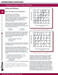
ENGINEERING GUIDELINES<br />
B<br />
B40<br />
TERMINAL CONTROLS AND ACCESSORIES<br />
Engineering Guidelines | Terminals, Controls and Accessories<br />
Terminals, Controls and Accessories<br />
Types of Terminals<br />
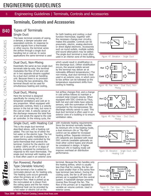
Single Duct<br />
This basic terminal consists of casing,<br />
a damper, a damper actuator and<br />
associated controls. In response to<br />
control signals from a thermostat<br />
or other source, the terminal varies<br />
the airflow through a single duct<br />
handling hot or cold air. In some<br />
applications the same terminal is used<br />
Dual Duct, Non-Mixing<br />
Essentially the same as two single duct<br />
terminals side-by-side, this terminal<br />
modulates the flow of hot and cold<br />
air in two separate streams supplied<br />
by a dual duct central air handling<br />
unit. Because there is no provision<br />
for mixing the two airstreams, this<br />
terminal should not be used for<br />
simultaneous heating and cooling,<br />
Dual Duct, Mixing<br />
Here the terminal is designed<br />
specifically for mixing hot (or<br />
tempered ventilation) and cold air in<br />
any proportion. When equipped with<br />
pneumatic controls, there is a velocity<br />
sensor in the hot air inlet, but none in<br />
the cold air inlet. A velocity sensor at<br />
the discharge measures the total flow<br />
of air and sends the signal to the cold<br />
air controller. In the mixing cycle, the<br />
Single Duct, with Heating Coil<br />
This is the single duct terminal<br />
described above, with a heating coil<br />
added. The coil may be of either the<br />
hot water or the electric type. The hot<br />
water coil is usually modulated by a<br />
proportioning valve controlled by the<br />
same thermostat that controls the<br />
terminal. Control for the electric coil<br />
is either 100% on-off or in steps of<br />
capacity, energized by contactors in<br />
response to the room thermostat. The<br />
single duct terminal with heating coil<br />
is most often used in an exterior zone<br />
Fan Powered, Parallel<br />
Type (Variable Volume)<br />
In this terminal a fan is added to<br />
recirculate plenum air, for heating only.<br />
The heating cycle occurs generally<br />
when the primary air is off or at<br />
minimum flow. Heat is picked up as<br />
the recirculated air is drawn from<br />
the ceiling space and the fan motor.<br />
Additional heat can be provided by<br />
a hot water or electric coil on the<br />
<strong>Titus</strong> <strong>2008</strong> - <strong>2009</strong> <strong>Product</strong> <strong>Catalog</strong> | <strong>www</strong>.<strong>titus</strong>-hvac.com<br />
for both heating and cooling; a dual<br />
function thermostat, together with<br />
the necessary change-over circuitry,<br />
makes this possible. Controls can be<br />
pneumatic, electric, analog electronic<br />
or direct digital electronic. Accessories<br />
such as round outlets, multiple outlets<br />
and sound attenuators may be added.<br />
The single duct terminal is most often<br />
used in an interior zone of the building,<br />
which would result in stratification in<br />
the discharge duct. (When stratification<br />
occurs, the several outlets served<br />
by the terminal may deliver air at<br />
noticeably different temperatures.) The<br />
non-mixing, dual duct terminal is best<br />
used in an exterior zone, in which zeroto-low<br />
airflow can be tolerated as the<br />
temperature requirement shifts from<br />
cooling to heating.<br />
hot airflow changes first, and a change<br />
in cold airflow follows to maintain a<br />
constant total (mixed) volume. When<br />
equipped with DDC controls by <strong>Titus</strong>,<br />
both hot and cold inlets have velocity<br />
sensors, with the summation of flows<br />
computed by the microprocessor. No<br />
discharge velocity sensor is used. This<br />
dual duct terminal is often used in an<br />
exterior zone of a building or to ensure<br />
ventilation rates.<br />
with moderate heating requirements.<br />
Since the terminal normally handles<br />
its minimum cfm in the heating mode,<br />
a dual minimum cfm or “flip-flop”<br />
control can be added for increased<br />
heating airflow. Separate minimum<br />
cfm setpoints are standard with most<br />
DDC controls (available optionally on<br />
most other control types) and should<br />
be considered in design. A higher<br />
minimum cfm in heating mode will<br />
improve overhead air distribution<br />
performance.<br />
terminal. Because the fan handles only<br />
the heating airflow, which is usually<br />
less than that for cooling, the fan can<br />
be sized smaller than in the series flow<br />
type terminal (see below). During the<br />
cooling cycle, the fan is off and cool<br />
primary air is supplied from the central<br />
system. A backdraft damper prevents<br />
reverse flow through the fan. The<br />
flow of the primary air is regulated by<br />
variable air volume controls. Used in<br />
exterior zones.<br />
for<br />
cooling only.<br />
Supply<br />
Figure 47. Elevation - Single Duct<br />
Hot<br />
Cold<br />
To<br />
Outlets<br />
Figure 48. Plan View - Dual Duct, Non-<br />
Mixing<br />
Hot<br />
Cold<br />
To<br />
Outlets<br />
To<br />
Outlets<br />
Figure 49. Plan View - Duct Duct,<br />
Mixing<br />
Supply<br />
To<br />
Outlets<br />
Hot Water<br />
or Electric<br />
Coil<br />
Figure 50. Elevation - Single Duct, with<br />
Heating Coil<br />
Primary<br />
Recirc.<br />
Backdraft<br />
Damper<br />
To<br />
Fan Outlets<br />
Figure 51. Plan View - Fan Powered,<br />
Parallel Type (Variable Volume)
Types of Terminals (continued)<br />
Fan Powered, Series Type<br />
(Constant Volume)<br />
The fan runs continuously, fed by a<br />
mixture of primary and plenum air.<br />
The more primary air is forced in, the<br />
less plenum air is drawn in. The result<br />
is variable volume from the central<br />
system, constant volume (and sound)<br />
to the room. Because the central<br />
system need only deliver air as far<br />
as the fan, the inlet static pressure<br />
Low Temperature<br />
Fan Terminals<br />
The fan terminal, with its inherent<br />
mixing, is well suited to handle the<br />
very cold air delivered by systems<br />
designed for air much colder than with<br />
conventional 55°F supply systems.<br />
In order to use standard diffusers,<br />
the primary air must be raised to<br />
Fan Powered, Low Profile<br />
This series or parallel type terminal<br />
has a vertical dimension of only 10.5”<br />
for all sizes, to minimize the depth<br />
of ceiling space required. Notice in<br />
the diagram at the right that the<br />
recirculating fan is laid flat on its<br />
side, shaft vertical. In localities where<br />
building heights are limited, the low<br />
profile terminal saves enough space<br />
to allow extra floors to be included<br />
Fan Powered, Access Floor<br />
Profile (Constant Volume)<br />
This series type terminal is designed to<br />
fit around the pedestal support grid of<br />
access, or raised, floor systems. In a<br />
typical access floor the grid is<br />
24” x 24”.<br />
ENGINEERING GUIDELINES<br />
Engineering Guidelines | Terminals, Controls and Accessories<br />
can be lower than in the parallel flow<br />
terminal (above). The fan, however,<br />
is sized to handle the total airflow.<br />
These are often used in applications<br />
where constant background sound and<br />
continuous airflow are desired.<br />
a conventional supply temperature<br />
before it enters the room. A<br />
commonly utilized solution is to mix<br />
it with recirculated air with a fan<br />
powered terminal. The most common<br />
application uses a Series Flow unit, but<br />
many applications have been utilized<br />
with Parallel units with a constant<br />
running fan.<br />
in a high-rise structure. Ceiling space<br />
can be as little as 12” to 14” deep.<br />
The low profile terminal is also useful<br />
in buildings constructed with precast<br />
concrete channel floors. The terminal<br />
can fit into the channel space with<br />
no extra depth required (Series type<br />
shown).<br />
The terminal can fit into the floor<br />
plenum without any modifications to<br />
the pedestal system.<br />
Primary<br />
Recirc.<br />
Figure 52. Plan View - Fan Powered,<br />
Series Type (Constant Volume)<br />
Primary<br />
Figure 53. Plan View - Fan Powered,<br />
Low Profile<br />
Primary<br />
Fan<br />
Recirculated<br />
<strong>Air</strong><br />
Fan<br />
Recirculated<br />
<strong>Air</strong><br />
Fan<br />
To<br />
Outlets<br />
To<br />
Outlets<br />
To<br />
Recirc. Outlets<br />
Figure 54. Plan View - Fan Powered,<br />
Access Floor Profile (Constant Volume)<br />
B<br />
B41<br />
<strong>Titus</strong> <strong>2008</strong> - <strong>2009</strong> <strong>Product</strong> <strong>Catalog</strong> | <strong>www</strong>.<strong>titus</strong>-hvac.com<br />
TERMINAL CONTROLS AND ACCESSORIES
ENGINEERING GUIDELINES<br />
B<br />
B42<br />
TERMINAL CONTROLS AND ACCESSORIES<br />
Engineering Guidelines | Terminals, Controls and Accessories<br />
Types of Controls<br />
Reaction to Duct Pressure Controls<br />
Pressure Independent<br />
With this type of control the terminal maintains the flow<br />
rate required to handle the heating or cooling load,<br />
regardless of system pressure fluctuations. It is the best<br />
choice where the system pressure will vary extensively<br />
and where precise control is essential. Key components in<br />
pressure independent control are the velocity sensor, which<br />
furnishes a continuous reading of the air velocity through<br />
the terminal, and the velocity controller, which processes<br />
this information along with signals from the thermostat. In<br />
the chart (Figure 55), vertical lines AB and EF represent<br />
minimum and maximum cfm settings which are adjustable<br />
at the controller. Line CD represents any cfm setting<br />
maintained by the controller in response to the thermostat.<br />
The damper will open and close as needed to hold the cfm<br />
constant up and down this vertical line for the full range<br />
of pressure drops shown. Notice that the vertical cfm lines<br />
are cut off by the diagonal line AE, which represents the<br />
pressure drop from inlet to outlet with the damper wide<br />
open. This is the minimum DP shown in our data.<br />
Pressure Dependent<br />
A terminal with this type of control is designed for those<br />
applications where neither pressure independence nor<br />
cfm limit regulation is required. An example is a variable<br />
volume makeup air supply in which the downstream duct<br />
pressure is held constant by other controls. The terminal<br />
consists essentially of a casing, a damper and a damper<br />
actuator. There is no controller and no velocity sensor; the<br />
damper moves in direct response to the thermostat or other<br />
signal input. The line AB (Figure 56) shows the typical<br />
performance characteristic. It represents a given damper<br />
setting, with the flow rate varying as the square root of the<br />
static pressure drop through the terminal. This, of course,<br />
is typical of any damper or fixed orifice. Lines CD and EF<br />
represent random additional settings as the damper opens<br />
to the full open position line GH. Line GH is the minimum<br />
pressure loss of the assembly.<br />
Most of the control types shown here have certain principle<br />
elements in common:<br />
Room Thermostat or Sensor<br />
The thermostat contains not only a temperature sensing<br />
element, but also a means of changing the setpoint. The<br />
room sensor used with the direct digital control system is<br />
simply an electronic temperature sensor; setpoint changes<br />
are handled along with other signal processing in the digital<br />
controller.<br />
Velocity Sensor<br />
Mounted in the inlet of the terminal, this device senses air<br />
velocity, which can easily be converted to airflow rate. The<br />
sensor’s signal provides feedback to monitor and directs the<br />
operation of the controller and damper actuator.<br />
<strong>Titus</strong> <strong>2008</strong> - <strong>2009</strong> <strong>Product</strong> <strong>Catalog</strong> | <strong>www</strong>.<strong>titus</strong>-hvac.com<br />
Note: Excessive airflow may lead to excessive noise. Pressure<br />
independent control has Minimum less opportunity Variablefor<br />
Maximum variable (and<br />
unwanted) sounds in the cfmoccupied<br />
cfm spaces. cfm<br />
Setting Setting Setting<br />
Pressure Drop in w.g.<br />
Pressure Drop in w.g.<br />
6.00<br />
4.00<br />
6.00<br />
2.00<br />
4.00<br />
1.00<br />
0.802.00<br />
0.60<br />
1.00<br />
0.400.80<br />
0.60<br />
0.20<br />
0.40<br />
Pressure Drop in w.g.<br />
0.100.20<br />
0.08<br />
0.06<br />
0.10<br />
0.08<br />
0.040.06<br />
0.020.04<br />
6.00<br />
4.006.00<br />
4.00<br />
2.00<br />
2.00<br />
1.00<br />
1.00<br />
0.60<br />
0.60<br />
0.40<br />
0.40<br />
Pressure Drop in w.g.<br />
0.20<br />
0.20<br />
0.10 0.10A A<br />
0.06 0.06<br />
0.04 0.04<br />
C C<br />
0.02 0.02<br />
Controller<br />
Commands from the thermostat or room sensor, together<br />
with feedback from the velocity sensor, are processed in<br />
the controller to regulate the damper actuator. Operation is<br />
pressure independent.<br />
Damper Actuator<br />
Minumum SP, Wide Open Damper<br />
Figure 55. Pneumatic Pressure Independent<br />
E E<br />
0.01 0.01<br />
100 100<br />
200 200<br />
Minimum B<br />
cfm<br />
Setting<br />
A<br />
B<br />
GG<br />
Damper<br />
Setting Damper<br />
#1Setting<br />
#1<br />
Damper<br />
Damper<br />
Setting<br />
Setting<br />
#2<br />
#2<br />
Damper<br />
Damper<br />
Setting Setting<br />
#3 #3<br />
Damper<br />
Setting<br />
Open<br />
300 300 400 400 500 600<br />
700 800 1000<br />
<strong>Air</strong><br />
<strong>Air</strong><br />
Flow,<br />
Flow,<br />
cfm<br />
cfm<br />
Variable D<br />
cfm<br />
Setting<br />
Maximum F<br />
cfm<br />
Setting<br />
Figure 56. Pneumatic Pressure Dependent<br />
The damper actuator opens and closes the damper to<br />
change the airflow, or to hold it constant, as dictated by the<br />
controller.<br />
D<br />
C<br />
F<br />
E<br />
Minumum SP, Wide Open Damper<br />
0.010.02<br />
100 200<br />
A<br />
300 400 500 600700<br />
800 1000<br />
0.01<br />
100<br />
<strong>Air</strong> Flow, cfm<br />
200 300 400<br />
<strong>Air</strong> Flow, cfm<br />
500 600700<br />
800 1000<br />
C<br />
E<br />
B<br />
B<br />
D<br />
D<br />
F<br />
F<br />
H
Types of Controls (continued)<br />
ENGINEERING GUIDELINES<br />
Engineering Guidelines | Terminals, Controls and Accessories<br />
Pneumatic systems<br />
In a pneumatic control system, the various components are<br />
powered by compressed air, usually at 15-25 psi, from a<br />
central system. The thermostat receives air at full pressure<br />
directly from the main air supply. In response to room<br />
temperature, the air pressure is modulated to the controller,<br />
which regulates the damper actuator. The sensor and<br />
controller compensate for changes in duct pressure so that<br />
operation is pressure independent.<br />
Electric Systems - Figure 58A<br />
Electric controls operate at low voltage, usually 24 VAC,<br />
supplied by a transformer which is often built into the<br />
control box of the terminal. The room thermostat has<br />
single-pole-double-throw contacts so that (in the cooling<br />
mode) a rise in temperature drives the damper actuator<br />
in the opening direction; a fall in temperature reverses<br />
the actuator. Since the electric system has no velocity<br />
sensor and no controller, there is no compensation for duct<br />
pressure fluctuations. Operation of the terminal is pressure<br />
dependent, the thermostat and room response time are<br />
typically much less than the actuator response time, and<br />
excessive room temperature variations are a likely result.<br />
Analog Electronic Systems - Figure 58B<br />
Like the electric controls, analog electronic controls operate<br />
at low voltage, usually 24 VAC, supplied by a transformer<br />
which is often built into the control box of the terminal.<br />
These controls, however, also include a velocity sensor of<br />
either the thermistor type, or pneumatic velocity sensor with<br />
electronic transducer, together with an electronic velocity<br />
controller that is pressure independent. The electronic<br />
thermostat can control both cooling and heating operations.<br />
Because of the pressure independent operation and<br />
integrated thermostat, excellent room temperature control<br />
can be achieved.<br />
Direct Digital Electronic Systems - Figure 58C<br />
Here again the power source is a low voltage supply. Signals<br />
from a pneumatic or electronic velocity sensor, together with<br />
signals from the room temperature sensor, are converted<br />
to digital impulses in the controller, which is a specialized<br />
microcomputer. The controller not only performs the reset<br />
and pressure independent volume control functions, but<br />
it also can be adjusted and programmed either locally<br />
or remotely for multiple control strategies, including<br />
scheduling. In addition, it can link to other controllers and<br />
interface with security, lighting, and other equipment.<br />
Control can be centralized in one computer.<br />
Line<br />
Pneumatic<br />
Pneum.<br />
Velocity<br />
Sensor<br />
T’Stat<br />
Main <strong>Air</strong><br />
Electric<br />
T’Stat<br />
Pneumatic<br />
Controller<br />
Figure 57. Pneumatic System<br />
Damper<br />
Pneum.<br />
Damper<br />
Actuator<br />
Figure 58A. Electric Pressure Dependent System<br />
Analog Electronic<br />
Velocity<br />
Sensor<br />
T’Stat<br />
Line<br />
Transformer<br />
Transformer-Usually 24 VAC<br />
Secondary<br />
Damper<br />
Electric<br />
Damper<br />
Actuator<br />
Figure 58B. Electric Pressure Independent System<br />
Direct Digital Electronic<br />
Velocity<br />
Sensor<br />
Line<br />
Room<br />
Sensor<br />
Damper<br />
Electric<br />
Damper<br />
Actuator<br />
Analog VAV<br />
Controller with<br />
Velocity Transducer<br />
Digital VAV<br />
Controller with<br />
Velocity Transducer<br />
Transformer-Usually 24 VAC<br />
Secondary<br />
Damper<br />
Electric<br />
Damper<br />
Actuator<br />
Figure 58C. Electric Pressure Independent System<br />
B<br />
B43<br />
<strong>Titus</strong> <strong>2008</strong> - <strong>2009</strong> <strong>Product</strong> <strong>Catalog</strong> | <strong>www</strong>.<strong>titus</strong>-hvac.com<br />
TERMINAL CONTROLS AND ACCESSORIES
ENGINEERING GUIDELINES<br />
B<br />
B44<br />
TERMINAL CONTROLS AND ACCESSORIES<br />
Engineering Guidelines | Terminals, Controls and Accessories<br />
Control Operation<br />
in Terminals<br />
Damper Operation<br />
Linearity (Figure 61) is the ideal<br />
characteristic for most damper<br />
applications. How nearly linear<br />
the operation is depends upon the<br />
percentage of the overall system<br />
pressure drop contributed by the wide<br />
open damper. Pressure independent<br />
control operations eliminate the effect<br />
of nonlinear dampers, but simulate<br />
the effect of a true linear damper<br />
to the system. For a linear damper<br />
characteristic, the damper is sized to<br />
contribute about 10% of the overall<br />
system resistance. Also (Figure 62),<br />
actuator torque must be sufficient<br />
to close the damper under all design<br />
conditions. In <strong>Titus</strong> terminals, the<br />
torque is always more than adequate.<br />
Direct Acting/Reverse Acting<br />
Pneumatic Thermostat Action<br />
In the direct acting pneumatic<br />
thermostat (Figure 63), a room<br />
temperature increase causes<br />
a corresponding increase in<br />
thermostat output. In the reverse<br />
acting thermostat (Figure 64), the<br />
sequence is the opposite. Because<br />
of these characteristics, direct acting<br />
thermostats are often used for cooling,<br />
reverse acting for heating. (With<br />
electronic systems, this term has<br />
no application.)<br />
Direct Reset/Reverse<br />
Reset Pneumatic Velocity<br />
Controller Action<br />
In the direct reset pneumatic velocity<br />
controller (Figure 65), an increase in<br />
thermostat output pressure causes a<br />
corresponding increase in controller<br />
cfm setting. The damper will open and<br />
close to maintain this cfm when duct<br />
pressures change. In the reverse reset<br />
controller (Figure 66) the same action<br />
results from a decrease in controller<br />
cfm setting.<br />
<strong>Titus</strong> <strong>2008</strong> - <strong>2009</strong> <strong>Product</strong> <strong>Catalog</strong> | <strong>www</strong>.<strong>titus</strong>-hvac.com<br />
100<br />
%<br />
cfm<br />
Oversized<br />
Damper<br />
Damper Opening, %<br />
Damper<br />
Sized for<br />
Linear<br />
Characteristic<br />
Figure 61. Linear Damper Operation Figure 62. Damper Torque Requirement<br />
100<br />
%<br />
cfm<br />
(Cooling)<br />
Room Temperature Increase<br />
Figure 63. Direct Acting Thermostat<br />
Action<br />
100<br />
%<br />
cfm<br />
(Cooling)<br />
Direct<br />
Acting<br />
Thermostat<br />
Direct<br />
Reset<br />
Thermostat<br />
Min<br />
Room Temperature Increase<br />
Max<br />
Figure 65. Direct Reset Pneumatic<br />
Velocity Controller<br />
100<br />
%<br />
cfm<br />
%<br />
cfm<br />
(Cooling)<br />
Maximum<br />
Torque<br />
Required<br />
Torque<br />
Open Closed<br />
Face Area x Total Pressure<br />
100<br />
Reverse<br />
Acting<br />
Thermostat<br />
Room Temperature Increase<br />
Figure 64. Reverse Acting Thermostat<br />
Action<br />
%<br />
cfm<br />
(Cooling)<br />
100 Max<br />
Room Temperature Increase<br />
Direct<br />
Reset<br />
Thermostat<br />
Min<br />
Figure 66. Reverse Reset Controller
Control Operation in Terminals (continued)<br />
Pneumatic Thermostat-<br />
Controller Combinations<br />
For systems supplying cold air when<br />
a direct acting pneumatic thermostat<br />
signals a direct acting controller<br />
(Figure 67), an increase in room<br />
temperature produces an increase<br />
in cfm setting. A reverse acting<br />
thermostat with a reverse reset<br />
controller produces the same result.<br />
A direct acting thermostat with a<br />
reverse reset controller or a reverse<br />
acting thermostat with a direct reset<br />
controller (Figure 68) will produce<br />
a decrease in cfm as the room<br />
temperature increases. With warm<br />
supply air, the logic is reversed.<br />
Actuator Terminology<br />
Pneumatic actuators have an internal<br />
spring which is overcome by control<br />
air pressure. When air pressure is less<br />
than the spring tension, the actuator<br />
will retract. Depending on how it is<br />
connected to a damper, the damper<br />
may open or close on increase in<br />
control signal. Electronic actuators,<br />
however, are typically “fail stopped”<br />
unless they have a return spring which<br />
is activated by a loss of control signal.<br />
These are several times the cost of “fail<br />
stopped” actuators. When normally<br />
open or normally closed actuators<br />
are specified in an electronic control<br />
project, the requirement is most often<br />
in error.<br />
Normally Open<br />
This describes a pneumatic operator<br />
which is configured so that on loss of<br />
air pressure the damper in the unit<br />
will open fully. These applications are<br />
typically ones where all like units are<br />
desired to be open for control purposes<br />
such as smoke removal or to prevent<br />
excessive pressure on system start-up.<br />
Normally Closed<br />
When air pressure is removed, the<br />
actuator will cause the damper in the<br />
unit to go fully closed. This is typically<br />
specified when an area is to be<br />
isolated.<br />
ENGINEERING GUIDELINES<br />
Engineering Guidelines | Terminals, Controls and Accessories<br />
G<br />
100<br />
%<br />
cfm<br />
Min<br />
Max<br />
DA Thermostat<br />
DA Controller<br />
or (COLD AIR)<br />
RA Thermostat<br />
DA Controller<br />
(HOT AIR)<br />
Room Temperature Increase<br />
Figure 67. DA Pneumatic Thermostat<br />
Signaling DA Controller Combination<br />
Pneumatic Control/<br />
Actuator Combinations<br />
Controllers and actuators work in<br />
concert to control space temperatures.<br />
With pneumatic controls the most<br />
common combinations are Direct<br />
Acting Normally Open (DANO) and<br />
Reverse Acting Normally Closed<br />
(RANC). With most pneumatic<br />
controls special controllers are used<br />
for direct and reverse acting and any<br />
combinations other than DANO or<br />
RANC require extra components and<br />
increase air consumption. (With the<br />
<strong>Titus</strong> II controller, no extra components<br />
are required as the unit is switchable.)<br />
H 100 Max<br />
%<br />
cfm<br />
DA Thermostat<br />
RA Controller<br />
or<br />
(HOT AIR)<br />
RA Thermostat<br />
RA Controller<br />
(COLD AIR)<br />
Min<br />
Room Temperature Increase<br />
Figure 68. RA Thermostat with Reverse<br />
Reset Controller or RA Thermostat with<br />
Direct Reset Controller Combination<br />
B<br />
B45<br />
<strong>Titus</strong> <strong>2008</strong> - <strong>2009</strong> <strong>Product</strong> <strong>Catalog</strong> | <strong>www</strong>.<strong>titus</strong>-hvac.com<br />
TERMINAL CONTROLS AND ACCESSORIES
ENGINEERING GUIDELINES<br />
B<br />
B46<br />
TERMINAL CONTROLS AND ACCESSORIES<br />
Engineering Guidelines | Terminals, Controls and Accessories<br />
Operation of a<br />
Velocity Controller<br />
Definitions of Terms<br />
The controller setpoint is the cfm<br />
setting that the control system is<br />
calling for at any given moment. At<br />
that setpoint the damper opening may<br />
vary widely to compensate for any duct<br />
pressure changes reported by the inlet<br />
sensor, and thus hold the cfm constant.<br />
With pneumatic systems, the setpoint,<br />
11 psi in the example (Figure 69),<br />
can be reset by the action of the<br />
thermostat anywhere between the<br />
maximum and minimum cfm settings<br />
of the controller. The corresponding<br />
thermostat output pressures are called<br />
the start and stop points. The range<br />
of possible setpoints between the start<br />
and stop points is called the reset<br />
span, 8 to 13 psi in the example shown<br />
here.<br />
The thermostat may also control an<br />
auxiliary piece of equipment, such as<br />
a proportioning valve on a hot water<br />
coil, shown here modulating over<br />
a range of 3 to 8 psi, in sequence<br />
with the reset span of the controller.<br />
The overall range over which the<br />
thermostat controls these devices is<br />
its proportional band or total throttling<br />
range, 3 to 13 psi in this example.<br />
Thermostat Sensitivity<br />
This is the change in output signal<br />
caused by a change in room<br />
temperature. This rating (Figure 70)<br />
is usually 1°F = 2.5 psi for pneumatic<br />
systems. Electronic systems have a<br />
wide variance in output responses.<br />
Hysteresis<br />
This is the failure of an object to return<br />
to its original position after a force has<br />
moved or deflected it. For example, in<br />
some velocity controllers (Figure 71)<br />
the cfm setting increases along the<br />
lower curved line and decreases along<br />
the upper curved line. At the setpoint,<br />
the cfm may be either A or B.<br />
<strong>Titus</strong> <strong>2008</strong> - <strong>2009</strong> <strong>Product</strong> <strong>Catalog</strong> | <strong>www</strong>.<strong>titus</strong>-hvac.com<br />
13<br />
8<br />
100<br />
% Max. Flow<br />
0<br />
Max. gpm<br />
Set<br />
Point<br />
(DDES)<br />
73 75 77<br />
Room Temperature<br />
Total Throttling Range<br />
of Thermostat<br />
Hot<br />
Water<br />
Valve<br />
Modulation<br />
Min. cfm<br />
Start<br />
Point<br />
3 8<br />
(Cooling)<br />
Thermostat Output, psi<br />
Figure 69. Set Point Example<br />
Set<br />
Point<br />
Thermostat Output, psi<br />
Figure 70. Thermostat Sensitivity Example Figure 71. Hysteresis Example<br />
cfm<br />
Reset Span<br />
of Controller<br />
(Cooling)<br />
B<br />
A<br />
Set<br />
Point<br />
11<br />
Min<br />
8<br />
13<br />
Max. cfm<br />
Stop<br />
Point<br />
13<br />
Max
Operation of a Velocity Controller<br />
(continued)<br />
Pneumatic Feedback<br />
Signals from the thermostat determine<br />
the cfm setpoint of the controller. The<br />
duct velocity acting on the velocity<br />
sensor forms a feedback (closed) loop<br />
(Figure 72) that allows the controller<br />
to monitor the airflow resulting from<br />
its settings and make corrections<br />
continuously. This is a form of closed<br />
loop control and is used on both<br />
pneumatic and electronic pressure<br />
independent systems.<br />
In the <strong>Titus</strong> ll pneumatic controller<br />
there is also an internal feedback<br />
loop that works in conjunction with<br />
a positive positioning reset mechanism<br />
to eliminate hysteresis (Figure 71,<br />
page B46).<br />
Fan Terminal<br />
Flow Control<br />
Engineers designing air systems try<br />
to match the airflow capacity of fan<br />
powered terminals to the needs of<br />
the space. Exact matches are rare,<br />
however. The design may not allow an<br />
exact match, a product other than the<br />
one which is the subject of the design<br />
might be selected, or system balancing<br />
might require a different airflow<br />
to meet field conditions. The two<br />
commonly used methods of trimming<br />
fan airflow are:<br />
• Mechanical Trimming<br />
• Voltage Adjustment<br />
Series Fan Shift<br />
With Series fan terminals, the fan<br />
output is intended to remain constant<br />
over a range of primary inlet damper<br />
flow rates. With proper design, this<br />
is normally so. With improper design,<br />
or with additional inlet attenuators<br />
added to a terminal, the fan may<br />
see a different external pressure<br />
when in full induction mode than<br />
when in full cooling. This results<br />
in a variation in the quantity of air<br />
delivered to the space, or “Fan Shift.”<br />
The consequences of fan shift depend<br />
on individual zone characteristics<br />
and building design. If diffusers are<br />
selected such that they may add<br />
background masking sound at design<br />
flow, variations in flow may be an<br />
annoyance to the occupants. If a<br />
designed ventilation rate is assumed,<br />
this may vary if fan shift happens.<br />
(<strong>Titus</strong> terminals are designed to<br />
minimize fan shift.)<br />
ENGINEERING GUIDELINES<br />
Engineering Guidelines | Terminals, Controls and Accessories<br />
T<br />
Thermostat<br />
100%<br />
SP<br />
0<br />
Controller<br />
Mechanical Trimming<br />
Mechanical trimming involves the<br />
use of a mechanical device, such as<br />
a damper, to adjust the fan airflow<br />
to meet the design requirements.<br />
Typically, these are used in conjunction<br />
with a multi-tap motor to provide a<br />
greater operating range and keep<br />
the energy consumption and sound<br />
levels as low as possible. Mechanical<br />
trimming offers a lower first cost<br />
versus a voltage adjustment, but<br />
at increased operating costs and<br />
increased sound. Multi-tap motors are<br />
not always effective in changing flow.<br />
In operation, the mechanical device<br />
will raise the static pressure the fan<br />
operates against by either restricting<br />
the free area downstream of the fan<br />
or restricting the free flow of air drawn<br />
into the fan. A forward curved fan<br />
riding the fan curve will reduce airflow<br />
accordingly (Figure 73).<br />
Transmitter<br />
Positive<br />
Positioning<br />
Reset<br />
Figure 72. Pneumatics Feedback<br />
Static Pressure<br />
Static<br />
Efficiency<br />
System<br />
Multi-Point<br />
Center Averaging<br />
Velocity Sensor<br />
Duct<br />
Velocity<br />
Completes<br />
Damper Feedback<br />
Actuator Loop<br />
100%<br />
Brake<br />
Horsepower<br />
Operating<br />
Point<br />
cfm 100%<br />
Figure 73. Forward Curved Fan Performance Curve<br />
BHP<br />
SE<br />
Although the rpm of the fan will<br />
increase, less work will be performed.<br />
This will result in a reduction of the<br />
amp draw of the fan motor. Since<br />
voltage remains constant, the overall<br />
power consumption of the fan is<br />
reduced. The power reduction from<br />
mechanical trimming is less, however,<br />
than the power reduction from<br />
voltage adjustment. When mechanical<br />
trimming is used, the sound levels of<br />
the fan terminal will increase. When<br />
the dampering occurs downstream of<br />
the fan, the velocity of the discharge<br />
air must rise, thereby increasing<br />
the discharge sound power levels.<br />
Additional sound contributions are<br />
made by the fan. The increased rpm<br />
of the fan results in greater tip speed.<br />
This occurs with either dampering<br />
method, raising the level of both the<br />
radiated and discharge sound.<br />
B<br />
B47<br />
<strong>Titus</strong> <strong>2008</strong> - <strong>2009</strong> <strong>Product</strong> <strong>Catalog</strong> | <strong>www</strong>.<strong>titus</strong>-hvac.com<br />
TERMINAL CONTROLS AND ACCESSORIES
ENGINEERING GUIDELINES<br />
B<br />
B48<br />
TERMINAL CONTROLS AND ACCESSORIES<br />
Engineering Guidelines | Terminals, Controls and Accessories<br />
Fan Terminal Flow Control (continued)<br />
Voltage Adjustment<br />
Voltage adjustment of fan powered<br />
terminals typically involves the use of<br />
a silicon controlled rectifier (SCR). An<br />
SCR uses a triac to phase proportion<br />
(chop) the electrical sine wave.<br />
In effect, the SCR switches power<br />
off 120 times a second on a 60 Hertz<br />
cycle. This reduces the voltage to the<br />
motor, slowing its speed. In operation,<br />
the SCR responds to the current but<br />
controls voltage. Thus, while an SCR’s<br />
triac may be energized at zero current,<br />
the current sine wave generally<br />
lags the voltage sine wave with an<br />
induction motor. This results in the<br />
idealized voltage sine wave (Figure<br />
74). As the SCR is used to further<br />
reduce fan speed, the true RMS value<br />
of the voltage is reduced.<br />
As voltage to the motor is reduced,<br />
the motor tries to compensate and the<br />
motor’s amp draw rises slightly. The<br />
amperes will continue to increase until<br />
50% of the current sine wave is phase<br />
proportioned. After this point, the amp<br />
draw will decrease. The increased amp<br />
draw is small relative to the reduction<br />
in voltage. As a result, comparing<br />
power consumption of the mechanical<br />
trimming method with the voltage<br />
adjustment method is analogous to<br />
comparing the power consumption<br />
of inlet guide vanes on central air<br />
handlers with speed inverters (Figures<br />
75 and 76).<br />
Fan Speed Control<br />
The rpm of the motor is reduced by<br />
the SCR, lowering the tip speed of the<br />
fan. Since the free area downstream<br />
of the fan is not reduced, the velocity<br />
either meets design conditions or<br />
is lowered if the airflow is reduced<br />
below design for balancing purposes.<br />
There is no increase in sound from air<br />
disturbances.<br />
<strong>Titus</strong> <strong>2008</strong> - <strong>2009</strong> <strong>Product</strong> <strong>Catalog</strong> | <strong>www</strong>.<strong>titus</strong>-hvac.com<br />
0<br />
Figure 74. Idealized Voltage Sine Wave Resulting from an SCR<br />
100%<br />
Watts<br />
0<br />
Figure 75. Watt Reduction Versus cfm<br />
Voltage<br />
Across Motor<br />
50% 100%<br />
<strong>Air</strong> Flow, cfm<br />
A Note on Nameplate Ratings<br />
The amp draw can increase above the nameplate<br />
rating of the motor! The motor’s nameplate<br />
specifies the amp draw for one set of design<br />
conditions. Since the voltage to the motor is<br />
reduced, the nameplate rating is no longer<br />
applicable. If proper care is taken in the design,<br />
specification and selection of the motor by the<br />
terminal manufacturer, the increased amp draw<br />
will pose absolutely no problem in operation or<br />
longevity. Thousands of fan powered terminals<br />
shipped with SCRs over the years serve as<br />
confirmation.<br />
<strong>Titus</strong> accounts for the increased amp draw in the<br />
specification and selection of motors used for<br />
fan powered terminals. As a result, <strong>Titus</strong> specifies<br />
unit fusing adequate to handle the maximum amp<br />
draw possible under all operating conditions. This<br />
differs from the motor nameplate; it is essential<br />
that electric circuit fuses/overcurrent protection<br />
are sized according to the nameplate of the<br />
terminal, not the motor nameplate.
Fan Speed Control (continued)<br />
<strong>Catalog</strong> Fan Curves<br />
The fan curves in a catalog represent<br />
the operating range of the fan powered<br />
terminal. Fan operation is dependent<br />
on the static pressure on the fan,<br />
so fan curves show airflow vs. static<br />
pressure. As the static pressure<br />
increases, airflow decreases. A typical<br />
fan curve will show maximum and<br />
minimum airflow for a fan powered<br />
terminal.<br />
In (Figure 77), the top curve<br />
represents the maximum airflow that<br />
the fan and motor can provide. This<br />
corresponds to the recommended<br />
maximum operating rpm of the motor.<br />
The bottom curve shows the minimum<br />
airflow that the fan and motor can<br />
provide. This corresponds to either the<br />
minimum operating rpm of the motor<br />
or the minimum voltage of the SCR fan<br />
speed controller.<br />
The SCR minimum is designed to<br />
protect the motor from operating<br />
below its recommended rpm. Most<br />
standard fan powered terminal motors<br />
must operate above a manufacturer’s<br />
specified rpm to effectively selflubricate.<br />
However, the relationship between<br />
rpm and SCR voltage is dependent of<br />
static pressure. At minimum voltage<br />
on the SCR, the motor rpm will be<br />
different at different static pressures.<br />
Because of this, there is a possibility<br />
that at minimum SCR voltage, the<br />
rpm will be below the motor minimum<br />
recommended operating rpm. When<br />
this happens, the cataloged fan curve<br />
will use minimum rpm to set the<br />
minimum fan curve, not minimum SCR<br />
voltage.<br />
To ensure proper motor operation,<br />
always operate a fan powered terminal<br />
with the cataloged fan curve.<br />
A Note on Meter Usage<br />
Many Digital Multi-Meters (DMMs)<br />
will provide erroneous readings<br />
when attempting to measure<br />
current or voltage near an SCR.<br />
These meters are designed for<br />
normal, smooth sine waves. The<br />
SCR, by changing the shape of<br />
the sine wave, throws off the<br />
readings from these meters. To<br />
measure the current voltage, a<br />
true RMS DMM designed for<br />
these conditions must be used.<br />
ENGINEERING GUIDELINES<br />
Engineering Guidelines | Terminals, Controls and Accessories<br />
WATTS<br />
90<br />
80<br />
70<br />
60<br />
50<br />
40<br />
30<br />
20<br />
10<br />
0<br />
60<br />
RMS VOLTS TO MOTOR<br />
VS<br />
MOTOR WATTS & RPM<br />
cfm<br />
Volts --- 115<br />
Amps --- .77 FLA<br />
Rise --- 40 C<br />
Type --- Permanent Split Capacitor<br />
BLOWER --- Squirrel Cage<br />
--- (2) 6" dia. x 6.5" wide<br />
70 80 90 100 110 120<br />
RMS VOLT TO MOTOR<br />
Figure 76. Watt, Volt and rpm Relationships<br />
1600<br />
1400<br />
1200<br />
1000<br />
800<br />
600<br />
400<br />
200<br />
0 0.1 0.2 0.3 0.4 0.5 0.6<br />
Static Pressure - Inches of Water<br />
Figure 77. Typical Fan Curve<br />
1050<br />
1000<br />
900<br />
800<br />
700<br />
600<br />
500<br />
400<br />
350<br />
320<br />
RPM<br />
B<br />
B49<br />
<strong>Titus</strong> <strong>2008</strong> - <strong>2009</strong> <strong>Product</strong> <strong>Catalog</strong> | <strong>www</strong>.<strong>titus</strong>-hvac.com<br />
TERMINAL CONTROLS AND ACCESSORIES
ENGINEERING GUIDELINES<br />
B<br />
B50<br />
TERMINAL CONTROLS AND ACCESSORIES<br />
Engineering Guidelines | Terminals, Controls and Accessories<br />
ECM Motors - Fan Powered Terminals<br />
Pressure Independent - Energy<br />
Efficient Analog Speed Settings<br />
ECM Motor Technology<br />
The ECM motor is an ultra-high efficiency, brushless DC<br />
motor with a unique microprocessor based motor controller.<br />
Motor efficiencies of 70% or better across the entire<br />
operating range of the motor saves considerable electrical<br />
energy when compared to conventional induction motors.<br />
The motor controller, when tuned to the fan powered<br />
terminal, provides a large turn down ratio and constant<br />
volume airflow regardless of changes in downstream static<br />
pressure operating against the fan. With the introduction<br />
of the ECM motor, factory setting of the fan cfm is now<br />
possible.<br />
Separate controls are required to enable field adjustment of<br />
fan speed. The fan speed control allows adjustments to be<br />
made three ways.<br />
• Manually with a screwdriver, similar to the SCR<br />
control.<br />
• Remotely (as an option) through the DDC controls<br />
using a laptop at the unit.<br />
• Remotely through the Building Management<br />
System.<br />
Harmonics<br />
Power for a given motor is drawn through the line in<br />
the form of a pure sine wave. This sine wave contains a<br />
fundamental frequency, in the US typically 60 Hz. When<br />
there exists other pure sine waves, each with individual<br />
frequencies, other than the fundamental frequency, they are<br />
called harmonics.These waves cause distortion or “noise” in<br />
the power line. Therefore, harmonic distortion is a collection<br />
of pure sine waves, including the 60 Hz fundamental<br />
frequency, which when summed together point by point in<br />
time creates distortion in the incoming line.<br />
Due to the way a standard split capacitor motor draws<br />
power, they have slightly fewer harmonic frequencies as<br />
compared to the ECM motor. The ECM motor, unlike the<br />
standard split capacitor motor, draws peak power only when<br />
needed, resulting in less electrical noise generation.<br />
As of 1999, the most stringent of limitations for harmonics<br />
is published in the CEI Standard 61000-3-2 and governs<br />
equipment sold and manufactured in Europe. These<br />
values set the ceiling for allowable harmonic levels. The<br />
critical maximum or peak amp values for a given harmonic<br />
level occur in the third harmonic closely followed by that<br />
of the fifth harmonic. Published data for a 1hp ECM<br />
without filtering capability violates the CEI limits. <strong>Titus</strong> has<br />
developed technology to decrease the harmonic frequencies<br />
while continuing to deliver peak power as it is requested.<br />
The <strong>Titus</strong> ECM motor meets the CEI criteria, as well as<br />
specified national and international harmonic limitations.<br />
<strong>Titus</strong> <strong>2008</strong> - <strong>2009</strong> <strong>Product</strong> <strong>Catalog</strong> | <strong>www</strong>.<strong>titus</strong>-hvac.com<br />
Energy Savings Potential<br />
The ECM motor, as applied to the <strong>Titus</strong> TQS fan powered<br />
terminal, offers significant energy savings over time to the<br />
owner when compared to conventional induction motors.<br />
<strong>Titus</strong> has evaluated an actual field trial and confirmed<br />
through bench testing an example of the potential energy<br />
savings when using the ECM motor. The following charts<br />
show the watt reduction associated with the ½ hp and 1<br />
hp ECM motor when compared to standard TQS units of<br />
equivalent application range.<br />
Watts<br />
Figure 78. Watt Reduction with 1 / 2 hp ECM Motor<br />
Note: TQS Size 6 with 1 hp ECM motor watt comparison to<br />
standard permanent split capacitor motor. The average watt<br />
reduction over the above range is 335 watts.<br />
Watts<br />
1200<br />
1000<br />
800<br />
600<br />
400<br />
200<br />
600<br />
500<br />
400<br />
300<br />
200<br />
100<br />
0<br />
0<br />
TQS Size 6 - 1hp ECM Motor<br />
1263 1350 1601 1786 1849 2081 2162 2200<br />
cfm<br />
TQS Size 4 - ½ hp ECM Motor<br />
509 752 1000 1415<br />
cfm<br />
Figure 79. Watt Reduction with 1 hp ECM Motor<br />
ECM<br />
SCR<br />
ECM<br />
SCR<br />
Note: TQS Size 4 with 1 / 2 hp ECM motor kW comparison to<br />
standard permanent split capacitor motor. The average watt<br />
reduction over the above range is 178 watts.
ECM Motors - Fan Powered Terminals (continued)<br />
ENGINEERING GUIDELINES<br />
Engineering Guidelines | Terminals, Controls and Accessories<br />
When evaluating this reduction in watts for energy usage<br />
the following table shows, at various usage rates, the annual<br />
savings per motor. Annual savings assume a run time of<br />
3000 hours per year (250 days at 12 hours/day).<br />
Table 9. Annual Savings per Motor<br />
Usage KW/hr reductions<br />
Rate 0.28 0.35 0.40<br />
$0.05 $43.08 $52.50 $60.75<br />
$0.06 $51.70 $63.00 $72.90<br />
$0.07 $60.31 $73.50 $85.05<br />
$0.08 $68.93 $84.00 $97.20<br />
$0.10 $86.16 $105.00 $121.50<br />
$0.12 $103.39 $126.00 $145.80<br />
$0.14 $120.62 $147.00 $170.10<br />
Also, reduction in demand charges must also be considered.<br />
Typically, demand charges are calculated during a 15-minute<br />
peak window. Some utilities will qualify the peak demand to<br />
only the summer months and use this peak as the monthly<br />
charge throughout the remainder of the year while other<br />
utilities will calculate demand charges using that months<br />
peak kW requirement. The savings associated with reduced<br />
demand charges are substantial, as demand charges are<br />
usually several dollars per kW. As an example, a typical<br />
multi-story office application may require 200 fan terminals.<br />
Each fan terminal equipped with an ECM motor may have<br />
approximately 0.4 kW reduction in power. This translates<br />
to an 80 kW reduction in demand and with a demand<br />
rate of $10.00 per kW equates to a potential $800 per<br />
month reduction in the demand charges. While this model<br />
is simplistic, it is indicative of the payback potential of<br />
the motor. Utilities will vary not only in price but also in<br />
calculation methods with contract kW’s versus actual kW<br />
usage so actual savings must be calculated according to<br />
local market conditions.<br />
Coupling the usage and demand savings associated with the<br />
ECM motors can provide a substantial savings throughout<br />
the life of the building.<br />
Direct Digital Control<br />
Applying Computers to Control<br />
With many years of experience, design engineers have<br />
established the basic principles of temperature control for<br />
heating, ventilating, and air conditioning (HVAC) systems.<br />
These control strategies have been applied utilizing<br />
conventional pneumatic, electric or analog electronic<br />
devices.<br />
Recent advances in micro-technology have made it possible<br />
to apply the power and precision of computers to HVAC<br />
control. Microprocessors, which cost less than ever before<br />
and offer superior computing power, are now suitable for<br />
application to individual air handlers, packaged heating/<br />
cooling units, VAV terminals or the entire HVAC system.<br />
Direct Digital Control<br />
Microprocessor-based controllers inherently perform direct<br />
digital control (DDC) and typically replace the conventional<br />
pneumatic or analog electronic controls. Digital controllers<br />
measure signals from sensors (input), process these signals<br />
in software (through the microprocessor), and initiate a<br />
corrective action to a controlled device (outputs) (Figure<br />
80). A more technical definition is provided in the ASHRAE<br />
1995 Systems and Applications Handbook.<br />
Advantages of DDC<br />
DDC systems offer several potential advantages over<br />
conventional counterparts.<br />
• DDC systems provide improved comfort and<br />
greater energy efficiency through precise and<br />
accurate control. Pneumatic and Analog systems<br />
utilizing proportional (P) control have the inherent<br />
characteristic of offset (Figure 81). Microprocessor<br />
based controls can eliminate offset by adding the<br />
integral (I) or reset action. Furthermore, addition<br />
of the derivative (D) action can result in a faster<br />
response and greater stability (Figure 82), but<br />
requires significant tuning.<br />
• DDC systems require less maintenance than<br />
A direct digital controller receives<br />
electronic signals from the sensors,<br />
converts the electronic signals to numbers<br />
and performs mathematical operations on<br />
these numbers inside the computer. The<br />
output from the computer takes the form<br />
of a number, and can be converted to a<br />
voltage or pneumatic signal to operate the<br />
actuator.<br />
conventional systems. Since there are no moving<br />
parts, periodic preventive maintenance (PM) tasks<br />
such as calibration, lubrication, cleaning and<br />
adjustments are seldom required.<br />
• Control strategies can be modified quickly and<br />
easily without the need to rewire, repipe or install<br />
additional components.<br />
B<br />
B51<br />
<strong>Titus</strong> <strong>2008</strong> - <strong>2009</strong> <strong>Product</strong> <strong>Catalog</strong> | <strong>www</strong>.<strong>titus</strong>-hvac.com<br />
TERMINAL CONTROLS AND ACCESSORIES
ENGINEERING GUIDELINES<br />
B<br />
B52<br />
TERMINAL CONTROLS AND ACCESSORIES<br />
Engineering Guidelines | Terminals, Controls and Accessories<br />
Direct Digital Control (continued)<br />
Sensors<br />
Temperature<br />
Humidity<br />
<strong>Air</strong> Flow<br />
<strong>Air</strong> Flow, cfm<br />
Inputs Microprocessor Outputs<br />
Figure 80. Direct Digital Controller Figure 81. Inherent Offset - Lost Energy Dollars and Sacrificed<br />
Comfort<br />
• Since microprocessor controllers are software<br />
based, multiple control sequences can be<br />
preprogrammed in memory thus allowing a single<br />
controller to be fully interchangeable between<br />
different equipment. For example, an application<br />
specific VAV controller may be used to control<br />
single duct, dual duct or fan powered terminals<br />
by simply choosing the appropriate operating<br />
sequence from a software library maintained on<br />
board every controller (Figure 83).<br />
• While functioning completely independent, digital<br />
controllers perform all essential functions necessary<br />
to control different pieces of HVAC equipment<br />
without interconnecting to other computers. In this<br />
way each piece of HVAC equipment has its own<br />
digital controller in the same way conventional<br />
systems would provide individual control panels.<br />
Cooling Only<br />
Morning Warmup<br />
Heating Min.<br />
Heating<br />
Heating Setpoint<br />
Dual Duct<br />
With or Without<br />
Hot / Cold Blending<br />
Slope Depends on rate and<br />
magnitude of space<br />
temperature change.<br />
Cooling Min.<br />
Deadband<br />
Room Temperature<br />
Heating / Cooling<br />
Changeover<br />
1F 1F<br />
<strong>Titus</strong> <strong>2008</strong> - <strong>2009</strong> <strong>Product</strong> <strong>Catalog</strong> | <strong>www</strong>.<strong>titus</strong>-hvac.com<br />
Controlled<br />
Devices<br />
Valve Actuator<br />
Damper<br />
Actuators<br />
Cooling Max.<br />
Cooling<br />
Cooling Setpoint<br />
Controlled<br />
Variable<br />
Controlled<br />
Variable<br />
Setpoint<br />
Figure 83. Frequently Used Control Sequences<br />
Time<br />
Setpoint<br />
Time<br />
Inherent<br />
Offset<br />
Figure 82. Offset Completely Eliminated - Improved Comfort<br />
and Less Energy Usage<br />
Fan Powered<br />
Variable Volume (Parallel Type)<br />
Recirculated <strong>Air</strong><br />
Primary <strong>Air</strong><br />
Fan Powered<br />
Constant Volume (Series Type)<br />
Total <strong>Air</strong> Flow<br />
Recirculated <strong>Air</strong><br />
Primary <strong>Air</strong>
Direct Digital Control (continued)<br />
DDC Distributed Processing<br />
Using a concept commonly referred<br />
to as distributed processing, DDC<br />
controllers can function as standalone<br />
devices. In this way if one controller<br />
fails, others throughout the system<br />
can continue to function unaffected.<br />
The controllers are connected over a<br />
system communication bus or local<br />
area network (LAN) for system wide<br />
sharing of information. This information<br />
is used to perform sophisticated<br />
building control strategies not possible<br />
with conventional noncommunicating<br />
systems. The network also allows<br />
system access locally through a<br />
personal computer or remotely via<br />
modem over telephone lines (Figure<br />
84).<br />
Sizing Basic Terminals<br />
from Capacity Tables<br />
ENGINEERING GUIDELINES<br />
Engineering Guidelines | Terminals, Controls and Accessories<br />
Certified <strong>Air</strong> Terminals<br />
To provide engineers with sound power data which can<br />
be compared on an even basis, leading air terminal<br />
manufacturers joined together under the <strong>Air</strong> Conditioning<br />
and Refrigeration Institute (ARI) to develop an industry<br />
standard for rating air terminals and certifying performance<br />
data. The result was ARI Standard 880, <strong>Air</strong> Terminals, and<br />
the 880 Certification Program. Standard 880 specifies the<br />
procedure, using a reverberant chamber, for developing<br />
sound power data. The certification program ensures<br />
manufacturers’ equipment performance meets their claims.<br />
Compliance with 880 is assured through third party testing.<br />
If a manufacturer fails to match claimed performance, the<br />
manufacturer must immediately rerate the terminal or lose<br />
the ability to use the ARI 880 seal. Another standard, ARI<br />
885, was developed at the same time to assist the engineer<br />
in using certified product data.<br />
Terminal selection involves a series of trade-offs. The<br />
designer needs to try to balance all of the constraining<br />
factors and select the terminal which meets overall<br />
needs best.<br />
Engineers who specify ARI Certified<br />
air terminals are assured that the<br />
manufacturer’s performance meets<br />
the manufacturer’s claims. This is<br />
protection for the engineer, the<br />
building owner and the building<br />
occupant.<br />
VAV<br />
Controlling<br />
HVAC Equipment<br />
Local Bus Network<br />
Controlling<br />
HVAC Equipment<br />
Local Bus Network<br />
Controlling<br />
HVAC Equipment<br />
System<br />
Interface<br />
Local Bus Network<br />
VAV<br />
VAV<br />
VAV VAV VAV<br />
VAV VAV VAV<br />
Modem<br />
Figure 84. System Access via Network<br />
Sizing Single Duct Terminals<br />
The starting point for sizing single duct terminals is to<br />
identify the type and model of controller. This is necessary<br />
because some controllers are more accurate at lower<br />
velocities than others.<br />
Once the type of control is identified, the minimum and<br />
maximum primary airflows should be considered against<br />
the published cfm range. The trade-offs start here. Some<br />
engineers will select terminals near the bottom of the cfm<br />
range to reduce sound levels since large inlets reduce face<br />
velocity. Others select terminals near the top of the cfm<br />
range to hold down equipment costs. Still other engineers<br />
believe that one should remain comfortably in the middle to<br />
avoid potential control problems resulting from low velocities<br />
and sound problems occurring at high velocities.<br />
All <strong>Titus</strong> products operate extremely well within the<br />
published cfm ranges. Therefore, low velocity control<br />
concerns can be eliminated. This leaves sound and first cost<br />
as the key issues. If the terminal is relatively small to begin<br />
with and will be located over a kitchen or hallway, sound will<br />
probably not be of concern and the designer may choose<br />
to slightly undersize the terminal. If, on the other hand,<br />
the terminal is located over office space, the designer may<br />
slightly oversize the terminal.<br />
The selection of an appropriate water coil should also be<br />
considered at this time. In some cases, a terminal may<br />
need to be increased in size in order to obtain the desired<br />
heat output from the coil. With single duct units, the water<br />
coil air pressure drop should be subtracted from the duct<br />
pressure when determining sound generation. The sound<br />
produced by the damper is proportional to the pressure drop<br />
across the damper and discharge water coils may reduce<br />
that pressure drop. Other significant downstream pressure<br />
drops should be considered, and their pressure drop<br />
subtracted as well.<br />
VAV<br />
VAV<br />
VAV<br />
B<br />
B53<br />
<strong>Titus</strong> <strong>2008</strong> - <strong>2009</strong> <strong>Product</strong> <strong>Catalog</strong> | <strong>www</strong>.<strong>titus</strong>-hvac.com<br />
TERMINAL CONTROLS AND ACCESSORIES
ENGINEERING GUIDELINES<br />
B<br />
B54<br />
TERMINAL CONTROLS AND ACCESSORIES<br />
Engineering Guidelines | Terminals, Controls and Accessories<br />
Sizing Basic Terminals from Capacity Tables (continued)<br />
Sizing Parallel Fan Powered Terminals<br />
Parallel flow (variable volume) fan powered terminals are<br />
selected based on their capacity to handle the primary<br />
airflow. The same rules which apply to the selection of<br />
single duct terminals can be used, except that water coils<br />
are not in the primary airstream path, and will not affect<br />
sound levels. The pressure drop of the water coils, however,<br />
which are on the fan inlet in <strong>Titus</strong> parallel fan units, must<br />
be added to the expected discharge pressure at the fan flow<br />
rate when entering the fan curve tables.<br />
The fan is selected based on the minimum airflow<br />
requirements for the space or the heating load required.<br />
In most cases the fan can be downsized from the cooling<br />
flow requirement considerably, reducing both first cost and<br />
operating cost. The fan is selected from the fan curves.<br />
The downstream static pressure of the secondary air<br />
may not be the same as the primary air, however. If the<br />
secondary airflow requirements are less than the primary<br />
air requirements, the static pressure will be reduced. The<br />
following equation can be used to determine the static<br />
pressure at reduced airflows. (Do not forget to add water<br />
coil pressure drops to the fan requirement).<br />
Ps 1 = Ps 1 (V 1 / V 2 ) 2<br />
Where: Ps 2 = Primary <strong>Air</strong> Static Pressure<br />
Ps 2 = Secondary (Fan) <strong>Air</strong> Static<br />
Pressure<br />
V 1 = Primary <strong>Air</strong> Velocity<br />
V 2 = Secondary (Fan) <strong>Air</strong> Velocity<br />
To select a <strong>Titus</strong> parallel fan powered terminal, refer to the<br />
published fan curves and primary air pressure drop curves,<br />
together with the application and sound power data.<br />
In the parallel flow type of unit, when the primary air is<br />
ON, the fan is typically OFF, and vice versa. As shown in<br />
the Figure 86, the primary air and the fan discharge air<br />
follow parallel paths into a common plenum. Therefore both<br />
airflows will encounter the same downstream resistance at a<br />
given flow rate.<br />
Since the primary and secondary airflows come from two<br />
different sources-and often at two different specified flow<br />
rates-the volume vs. pressure relationship in each of these<br />
airflows must be checked to ensure adequate flow rates<br />
under actual job conditions.<br />
Example: Select a Model DTQP for a maximum of<br />
1400 cfm of primary air with 1.00” wg inlet static pressure.<br />
The fan airflow required is 1150 cfm. The downstream<br />
resistance offered by the duct and diffusers has been<br />
determined to be 0.30” static pressure at 1150 cfm.<br />
Primary <strong>Air</strong>: From the chart on page R46, a size 4 with a 12”<br />
inlet will handle 1400 cfm of primary air with a minimum<br />
static pressure drop of 0.22” through the primary air section.<br />
But since the downstream resistance is 0.30” at 1150 cfm,<br />
o 1400 2<br />
p<br />
1150<br />
x 0.30” = 0.44” sp<br />
<strong>Titus</strong> <strong>2008</strong> - <strong>2009</strong> <strong>Product</strong> <strong>Catalog</strong> | <strong>www</strong>.<strong>titus</strong>-hvac.com<br />
The overall primary air static pressure drop is<br />
0.22”+ 0.44”= 0.66” sp<br />
Since a 1.0” static pressure is available at the inlet, the<br />
selection will work. The damper in the primary air section<br />
Recirculated<br />
<strong>Air</strong><br />
Primary<br />
<strong>Air</strong><br />
Fan<br />
Primary<br />
<strong>Air</strong><br />
Section<br />
Figure 85. Schematic Diagram of <strong>Air</strong>flow in Parallel Flow<br />
(Variable Volume) Models<br />
Primary<br />
Secondary<br />
Either / Or<br />
Backdraft<br />
Damper<br />
Downstream Duct<br />
and Diffuser<br />
To<br />
Outlets<br />
Figure 86. Actual Arrangement of Components Shown in the<br />
Previous Schematic Diagram<br />
will do some throttling to hold the maximum air flow to<br />
1400 cfm.<br />
Secondary <strong>Air</strong> (Fan): From the fan curves, a size 4, without<br />
coils, terminal will handle 1150 cfm at 0.30” static pressure,<br />
with the proper setting of the standard SCR speed control.
Sizing Basic Terminals from Capacity Tables (continued)<br />
ENGINEERING GUIDELINES<br />
Engineering Guidelines | Terminals, Controls and Accessories<br />
Sizing Series Fan Powered Terminals<br />
Compared to single duct terminals, series flow (constant<br />
volume) fan powered terminals add the additional factor of<br />
fan cfm requirements. The designer must consider both the<br />
primary airflow and the fan. Series terminals are selected<br />
based on the capacity of their fans. The secondary (or fan)<br />
cfm should be equal to or slightly more than the primary<br />
air to ensure primary air does not short circuit through the<br />
induced air port into the plenum, thereby wasting energy.<br />
Before selecting the fan, the static pressure downstream of<br />
the terminal must be determined. This is the resistance of<br />
the ducts and diffuser(s) at design airflow rates.<br />
Once the downstream static pressure is known, the designer<br />
can select the fan based on the fan curves (these are shown<br />
throughout the catalog with the performance data for<br />
each fan powered terminal). The designer should find the<br />
intersection of the static pressure line on the horizontal axis<br />
and the fan cfm on the vertical axis. Selecting toward the<br />
upper end of the range will ensure that first costs are kept<br />
low and the fan motor efficiency is high. Selecting below the<br />
indicated minimum flow will result in shortened motor life as<br />
the bearings in the motor are centrifugally lubricated.<br />
If a water coil is needed, the designer must use the curves<br />
provided for a one or two row coil. These curves account<br />
for the additional static pressure generated by the coil. The<br />
static pressure added for an electric coil is negligible and<br />
may be disregarded. Neither has an appreciable effect on<br />
sound levels.<br />
Inlet size must also be selected. Fan powered terminals<br />
come with varying inlet sizes. In general, inlets should be<br />
selected toward the bottom of the range. This reduces the<br />
face velocity of the inlet and minimizes the sound generated<br />
by the primary air valve.<br />
To select a <strong>Titus</strong> series fan powered terminal unit, refer<br />
to the published fan curves and primary air pressure drop<br />
curves together with the application and sound power data.<br />
An abbreviated table is shown at the right for use with the<br />
example discussed here.<br />
In the series flow type of unit, the fan runs continuously in<br />
the standard version. With the optional night shutdown and<br />
night setback controls, the fan can be cycled ON and OFF<br />
when the primary air is OFF.<br />
As shown in the diagrams below, the primary air is drawn<br />
into the fan inlet along with secondary (recirculated) air<br />
from the room. The maximum primary airflow must always<br />
be equal to, or less than, the total airflow through the fan.<br />
When the primary air section reduces its airflow in response<br />
to a reduced demand for cooling, the fan makes up the<br />
difference by drawing more recirculated air from the room.<br />
As a result, the flow rate to the room is constant.<br />
The primary air section discharges into the unit casing near<br />
the fan inlet, where the static pressure is slightly below<br />
atmospheric. For this reason, the available inlet pressure<br />
need only be enough to overcome the internal pressure drop<br />
through the primary air damper itself.<br />
Example: Select a Model DTQS for a maximum of<br />
1200 cfm of primary air at 0.50” wg inlet static pressure.<br />
The fan airflow is 1200 cfm. The downstream resistance<br />
offered by the duct and diffusers is 0.30” at 1200 cfm.<br />
Primary <strong>Air</strong>: From the table on page R11, a size 4 will handle<br />
1200 cfm of primary air with a minimum static pressure drop<br />
of .2” through the primary air section. Since 0.50” static<br />
pressure is available at the inlet, the selection will work.<br />
Secondary <strong>Air</strong> (Fan): From the published fan curves, a size 4<br />
terminal will handle 1200 cfm at 0.30” static pressure, with<br />
the proper setting of the standard SCR speed control.<br />
Recirculated<br />
<strong>Air</strong><br />
Primary Primary<br />
<strong>Air</strong><br />
<strong>Air</strong> Section<br />
Figure 87. Schematic Diagram of <strong>Air</strong>flow in Constant Volume<br />
(Series Flow) Models<br />
Primary<br />
Secondary<br />
Internal ∆P s<br />
Fan<br />
Downstream Duct<br />
and Diffuser<br />
Downstream ∆P (Fan)<br />
s<br />
To<br />
Outlets<br />
Figure 88. Actual Arrangement of Components Shown in the<br />
Previous Schematic Diagram<br />
B<br />
B55<br />
<strong>Titus</strong> <strong>2008</strong> - <strong>2009</strong> <strong>Product</strong> <strong>Catalog</strong> | <strong>www</strong>.<strong>titus</strong>-hvac.com<br />
TERMINAL CONTROLS AND ACCESSORIES
ENGINEERING GUIDELINES<br />
B<br />
B56<br />
TERMINAL CONTROLS AND ACCESSORIES<br />
Engineering Guidelines | Terminals, Controls and Accessories<br />
Typical Problems<br />
Oversizing Terminal<br />
The direct result of oversizing is low air velocity. With the<br />
velocity too low, the damper must operate in a pincheddown<br />
condition most of the time, making control difficult.<br />
The inlet velocity can also be too low for effective operation<br />
of the sensor and controller. Too low a velocity through an<br />
electric heater will cause the safety airflow switch to shut<br />
down the heater. Oversizing fan terminals results in low<br />
fan motor rpm and the potential for under-lubrication of<br />
the motor bearings, resulting in shortened motor life and<br />
additional sound from larger motors (Figure 89).<br />
Capacity Concentrated in Too Few Terminals<br />
When one large terminal serves a space that should be<br />
served by two or more smaller ones, comfort problems can<br />
result. There may be noticeable temperature differences<br />
between rooms, since the thermostat is located in just one<br />
room as at the right. Also, for a given air velocity, the larger<br />
the terminal the more sound power it generates (Figure<br />
90).<br />
Insufficient Space<br />
Carefully planning the locations of the terminals avoids<br />
problems with installation, performance, and maintenance.<br />
In the example shown at the right, the control side of the<br />
terminal is against the wall, making connections difficult and<br />
service almost impossible. The cramped location also creates<br />
the need for close-coupled duct elbows, which reduce<br />
performance (Figure 91).<br />
Improper Discharge Conditions<br />
The duct connections at the discharge end of the terminal<br />
have a major effect on pressure drop. A tee close to the<br />
discharge is especially to be avoided, along with transition<br />
pieces and elbows. Another common error is running too<br />
much flex duct, as at the right. It would have been better to<br />
continue the rectangular duct to the last diffuser, then install<br />
short flex branches (Figure 92).<br />
Improper Inlet Conditions<br />
The arrangement of duct at the terminal inlet affects both<br />
pressure drop and control accuracy.<br />
The conditions shown at the right will create turbulence at<br />
the inlet. This makes it difficult for the sensor to measure<br />
airflow accurately. Although <strong>Titus</strong> velocity sensors correct<br />
for a considerable amount of turbulence, the best practice is<br />
to use straight duct at the inlet the same size or larger than<br />
the inlet (Figure 93).<br />
<strong>Titus</strong> <strong>2008</strong> - <strong>2009</strong> <strong>Product</strong> <strong>Catalog</strong> | <strong>www</strong>.<strong>titus</strong>-hvac.com<br />
Velocity too low for<br />
accurate dampering<br />
Terminal<br />
Tee at<br />
Discharge<br />
Terminal<br />
Large terminal<br />
serves more<br />
than one zone.<br />
Total<br />
damper travel<br />
Velocity too low<br />
for sensor<br />
Velocity too low for<br />
accurate dampering<br />
Figure 89. Low Velocity Effects<br />
Room 101<br />
Too Hot<br />
Figure 90. Too Few Terminals Effect<br />
Controls Coil Connections<br />
Terminal<br />
Figure 91. Installation Affecting Performance<br />
Terminal<br />
Figure 92. Improper Discharge Conditions<br />
Inlet tapped<br />
Tight elbow<br />
into side of duct at inlet<br />
Figure 93. Improper Inlet Conditions<br />
Velocity too low for<br />
electric heater<br />
Room 103<br />
T<br />
Pipe<br />
Chase<br />
Too much<br />
flex duct<br />
Supply duct<br />
smaller than inlet
3 Phase<br />
3 Wire<br />
4.5 ft.<br />
X 150 fpm<br />
ENGINEERING GUIDELINES<br />
Engineering Guidelines | Terminals, Controls and Accessories<br />
Figure 94. Power Source Compatibility<br />
Figure 95. Overhead Heated <strong>Air</strong><br />
Terminal Coil<br />
Large, Heavy Terminal<br />
Supported by Duct Work<br />
L1<br />
L2<br />
L3<br />
Figure 96. Possible <strong>Air</strong> Leakage<br />
Figure 97. Terminal Support<br />
Skin Added<br />
to Insulation<br />
3 Phase<br />
4 Wire Wye<br />
150 100 50<br />
Branch Take-off<br />
Diffuser<br />
Neck<br />
Figure 98. Anti-Erosion Skin Effects<br />
Joint<br />
L1<br />
L2<br />
Neutral<br />
L3<br />
Hanger Straps Screwed to Terminal<br />
Insulation Lacks<br />
Anti-Erosion Skin<br />
Typical Problems (continued)<br />
Incompatibility with Power Source<br />
In fan powered terminals, electrically or electronically<br />
controlled terminals, and all terminals with electric heating<br />
coils, the order to the factory should be carefully checked<br />
against the electrical characteristics of the power source at<br />
the point of connection.<br />
Not only must the voltage, phase, and frequency match, but<br />
the distinction between 3 phase-3 wire and 4 wire wye must<br />
be observed (Figure 94).<br />
Excessive <strong>Air</strong> Temperature Rise<br />
and <strong>Air</strong> Change Effectiveness<br />
The Discharge temperature for terminal units should be<br />
selected so the maximum temperature between the room<br />
and the diffuser discharge is no greater than 15BF. This<br />
can be found in the ASHRAE Handbook of Fundamentals.<br />
According to ASHRAE 62.1 2004, ceiling diffusers which<br />
have ceiling returns and are used for heating, should be<br />
mounted as shown to allow the supply air jet of 150 fpm to<br />
come down the exposed wall to within 4.5 ft. of the floor<br />
level. This reduces the short circuiting of warm air at the<br />
ceiling level and can be used as an alternative to using the<br />
Ez air change effectiveness value of 1.0 as determined in<br />
ASHRAE Standard 129 for all air distribution configurations<br />
except unidirectional flow (Figure 95).<br />
Excessive <strong>Air</strong> Leakage<br />
Leakage from the branch duct upstream and downstream<br />
from the terminal, as well as from the terminal itself, can be<br />
serious. In some installations it is found to be as much as<br />
10% or more of the total airflow.<br />
Most of this leakage can be avoided by careful fabrication<br />
and installation and the use of top quality terminals<br />
(Figure 96).<br />
Improper Support Of Terminal<br />
Many terminals are light enough to need no support other<br />
than the duct work itself. However, the larger sizes, units<br />
with electric coils and fan powered models, are heavy<br />
enough to require additional support. A practical method is<br />
to use hanger straps screwed to the sides of the terminal.<br />
The bottom should be left clear where there are access<br />
panels (Figure 97).<br />
Wrong Type of Insulation<br />
Installations in hospitals, clean rooms, and laboratories<br />
often require a special insulation liner to prevent air erosion<br />
or microbial growth. In the past, Mylar and Tedlar were<br />
often specified in these installations. Neither, however, meet<br />
current safety codes in many cities. Foil faced insulations,<br />
such as Micro-Loc and Steri-Loc, provide the required<br />
covering, meet all safety codes and actually provide some<br />
sound attenuation. <strong>Titus</strong> Fibre-Free insulation provides<br />
both sound attenuation and resistance to erosion and mold<br />
growth (Figure 98).<br />
B<br />
B57<br />
<strong>Titus</strong> <strong>2008</strong> - <strong>2009</strong> <strong>Product</strong> <strong>Catalog</strong> | <strong>www</strong>.<strong>titus</strong>-hvac.com<br />
TERMINAL CONTROLS AND ACCESSORIES
ENGINEERING GUIDELINES<br />
B<br />
B58<br />
TERMINAL CONTROLS AND ACCESSORIES<br />
Engineering Guidelines | Terminals, Controls and Accessories<br />
Typical Problems (continued)<br />
Non-Compliance with Local Codes<br />
Some localities have stringent codes of their own, with<br />
requirements beyond those of NEC, UL, and CSA. An<br />
example is the primary fusing in the control transformer at<br />
the right (Figure 99).<br />
Installation Techniques-Duct Connections<br />
The inlet duct slips over the inlet collar of the terminal.<br />
It should be fastened and sealed according to the job<br />
specifications.<br />
The diameter of the inlet duct must be equal to the listed<br />
size of the terminal. For example, a duct that measures 8” in<br />
diameter must be fitted to a size 8 terminal. The inlet collar<br />
of the terminal is made ⅛” smaller than nominal size in<br />
order to fit inside the duct (Figure 100).<br />
Note: A duct should never be inserted inside the inlet collar<br />
of the terminal.<br />
For optimum control accuracy, a straight section<br />
of unrestricted duct at least 1½ diameters long should be<br />
installed at the inlet (Figure 101). Where this condition<br />
does not exist, field adjustment of the airflow setting on the<br />
velocity controller may be required.<br />
If space does not permit using the 1½ diameter length of<br />
straight duct, a hard duct elbow up to 90° can be installed<br />
at the inlet of the <strong>Titus</strong> terminal without altering the factory<br />
maximum or minimum airflow setting by more than 10%<br />
(Figure 102).<br />
The outlet end of the <strong>Titus</strong> terminal is designed for a<br />
slip and drive connection. Unless a round duct adapter<br />
is furnished, a rectangular outlet duct should be fitted to<br />
match the size of the terminal casing. It should be fastened<br />
and sealed according to the job specifications.<br />
If a round outlet adapter is furnished, it should be fastened<br />
and sealed by the same method used for the inlet.<br />
Close coupling the terminal inlet to the side of the main<br />
supply duct is not recommended. Where this condition is<br />
unavoidable, a flow straightening device (Figure 103)<br />
should be installed between the main supply duct and<br />
the inlet to the terminal. Even with the flow straightening<br />
device, the terminal may still require some field adjustment<br />
of the factory airflow settings at the velocity controller.<br />
<strong>Air</strong> leakage adds significantly to the operating cost of an<br />
HVAC system. Important savings are realized by carefully<br />
fitting and sealing all duct joints and specifying tightly<br />
constructed <strong>Titus</strong> terminals. The <strong>Titus</strong> box has very low<br />
damper and casing loss leakage. These values can be found<br />
on page Q26.<br />
<strong>Titus</strong> <strong>2008</strong> - <strong>2009</strong> <strong>Product</strong> <strong>Catalog</strong> | <strong>www</strong>.<strong>titus</strong>-hvac.com<br />
277 VAC<br />
277 VAC<br />
Figure 99. Primary Fusing in the Control Transformer<br />
Straight Duct<br />
Figure 100. Terminal Inlet Collar Fitting Properly<br />
Flexible Duct<br />
Fuse<br />
Inlet<br />
Inlet<br />
Transformer<br />
Terminal<br />
24 VAC<br />
24 VAC<br />
Figure 101. Unrestricted Duct Properly Install at the Inlet<br />
Hard<br />
Duct<br />
Elbow<br />
1.5 Diameter<br />
Minimum<br />
Inlet<br />
Terminal<br />
Terminal<br />
Figure 102. 90 Degree Hard Elbow Duct Installed to Inlet<br />
Main Supply<br />
Duct<br />
Inlet<br />
Terminal<br />
<strong>Air</strong><br />
Straightener<br />
Figure 103. Flow Straightening Device Placement
Terminal Coil<br />
ENGINEERING GUIDELINES<br />
Engineering Guidelines | Terminals, Controls and Accessories<br />
Figure 104. Possible <strong>Air</strong> Leakage<br />
A 10” terminal handles 1150 cfm. The central system cools<br />
air from 80°F dry bulb / 67°F wet bulb to 53°F dry bulb /<br />
51.5°F wet bulb before sending it to the terminal.<br />
Cost of Refrigeration<br />
The total heat removed from the system is:<br />
31.65 Btu/# at 80/67 minus 21.10 Btu/# at<br />
53/51. = 10.45 Btu/# of dry air.<br />
The amount of leakage given in this example is 58 cfm.<br />
The loss of refrigeration energy through leakage is:<br />
58 cfm x 10.45 Btu/# x 4.5 = 2727 Btu/hr.<br />
Assuming a cooling system EER of 7.5 overall (reference<br />
ASHRAE Standard 90), in a space where the system<br />
operates 24 hours a day, 365 days a year, (worst case)<br />
At a power cost of $0.06 per kwh, 0.3636 x $0.06 x 24 x<br />
365 = $191.11<br />
If the system operates at 40% capacity, averaged over:one<br />
2727<br />
7.5 x 1000<br />
Branch Take-off<br />
Diffuser<br />
Neck<br />
= .0.3636 kWh input<br />
Joint<br />
year, $191.11 x 0.40 = $76.44, the cost of wasted<br />
refrigeration power alone, again worst case, assuming<br />
continuous operation.<br />
Example of Leakage Costs<br />
Typical Problems (continued)<br />
The example in (Figure 104) shows how many dollars<br />
can be lost in the leakage from just one terminal together<br />
with its connected duct work. Multiply that amount by the<br />
hundreds or thousands of terminals that may be in one<br />
building, and the seriousness of the loss is apparent.<br />
This is a conservative example, in that the leakage is<br />
only 5%; a much higher percentage is found in many<br />
installations. Also, the compressor, pumps, and fans may not<br />
run as efficiently as indicated here, and the cost of electric<br />
power in many parts of the country is greater than $0.06<br />
per kilowatt hour.<br />
The amount of leakage in the branch duct serving the<br />
terminal, the connections to the terminal, the terminal<br />
itself, and the duct downstream from the terminal is 5% of<br />
the 1150 cfm being handled, or about 58 cfm.<br />
Cost of Fan Operation<br />
If the static pressure across the fan is 5” wg and the fan<br />
static efficiency averages 75%, the leakage converts to:<br />
Assuming that the motor efficiency multiplied by the power<br />
factor averages 0.80,<br />
0.0569 x $0.06 x 24 x 365 x 0.40 = $11.96,<br />
the cost of wasted fan power.<br />
Combined cost equals:<br />
$76.44<br />
$11.96<br />
$88.40<br />
58 cfm x 5<br />
6356 x 0.75<br />
0.061 x 746<br />
0.080 x 1000<br />
= .0.061 bhp<br />
= .0.0569 kw<br />
per year for one terminal.<br />
B<br />
B59<br />
<strong>Titus</strong> <strong>2008</strong> - <strong>2009</strong> <strong>Product</strong> <strong>Catalog</strong> | <strong>www</strong>.<strong>titus</strong>-hvac.com<br />
TERMINAL CONTROLS AND ACCESSORIES
ENGINEERING GUIDELINES<br />
B<br />
B60<br />
TERMINAL CONTROLS AND ACCESSORIES<br />
Engineering Guidelines | Terminals, Controls and Accessories<br />
Some Basic Concepts-Pressure Measurement<br />
Three categories of pressure are<br />
connected with air handling:<br />
1. Static pressure may be thought of<br />
as the pressure in a tire or storage<br />
tank. It is exerted in all directions<br />
equally.<br />
2. Velocity pressure, as its name<br />
implies, is entirely a function of<br />
air velocity and its direction. It is<br />
the pressure you feel against your<br />
hand if you hold it outside the<br />
window of a moving car.<br />
3. Total pressure is the sum of static<br />
pressure and velocity pressure.<br />
It and static pressure are the<br />
pressures actually sampled by<br />
velocity sensors in terminals and<br />
by commonly used measuring<br />
devices, as described next.<br />
The interaction of static, velocity, and<br />
total pressures is illustrated by<br />
(Figure 105). The Pitot tube, which<br />
is used to measure velocities and<br />
pressures, is really a tube within a<br />
tube. The inner, or impact, tube senses<br />
both the velocity pressure and static<br />
pressure combined (total pressure).<br />
The outer tube, which communicates<br />
with the airstream through small holes<br />
in its wall, avoids the impact of the<br />
air movement and senses only static<br />
pressure.<br />
The U-tube manometer, connected to<br />
both parts of the Pitot tube, has the<br />
effect of subtracting static pressure<br />
from total pressure to give a reading of<br />
velocity pressure.<br />
Once the velocity pressure is known,<br />
the velocity can be calculated easily:<br />
where V = <strong>Air</strong> Velocity<br />
P = o<br />
v V p<br />
4005<br />
and<br />
P v = Velocity Pressure<br />
Knowing both the velocity and the<br />
cross-sectional area of the duct, the<br />
flow rate is then:<br />
cfm = Area x Velocity<br />
<strong>Titus</strong> <strong>2008</strong> - <strong>2009</strong> <strong>Product</strong> <strong>Catalog</strong> | <strong>www</strong>.<strong>titus</strong>-hvac.com<br />
2<br />
or V = 4005√P v<br />
P T<br />
P S<br />
P S<br />
Pitot Tube<br />
Connecting<br />
Tubing<br />
P V Difference in Liquid Level<br />
P T minus P S = P V<br />
Glass Manometer Tube<br />
P T<br />
Figure 105. Static, Velocity and Total Pressures Interaction
The Fan Laws<br />
The Fan Laws are basic tools in air handling. Three of the<br />
most common relationships are illustrated as follows.<br />
Example:<br />
A fan handles 40,000 cfm at 2” static pressure. It runs<br />
at 760 rpm and draws 18 brake horsepower. The fan is<br />
increased to 800 rpm. What are the new cfm, sp,<br />
and bhp?<br />
1. <strong>Air</strong>flow rate varies directly with shaft speed.<br />
2.<br />
cfm1 rpm1<br />
=<br />
cfm2 rpm2<br />
cfm2 = (cfm1 x rpm2) / rpm1<br />
= (40,000 x 800) / 760<br />
= 42,105<br />
3. Pressure varies as the square of shaft speed.<br />
P2 = P1 x rpm22 / rpm12 = 2 x (800) 2 / (760) 2<br />
P1 rpm1<br />
= 2.22”<br />
2<br />
P2 rpm22 =<br />
4. Horsepower varies as the cube of shaft speed.<br />
ENGINEERING GUIDELINES<br />
Engineering Guidelines | Terminals, Controls and Accessories<br />
bhp1 = rpm1 3<br />
bhp2 = ((bhp1) x (rpm2) 3 / (rpm1) 3<br />
= ((18) x (800) 3 ) / (760) 3<br />
= 21.0<br />
The relationships stated here apply when the air density<br />
remains constant and when there is no change in the fan<br />
or the system. They are based on Fan Laws 1, 2 and 3. For<br />
a complete presentation of the Fan Laws, see the ASHRAE<br />
Handbook, Systems and Equipment.<br />
Each fan design has its characteristic set of performance<br />
curves. Those shown in (Figure 109) are typical of a<br />
centrifugal fan with forward curved blades in the wheel,<br />
as commonly used in fan powered terminals. For a full<br />
discussion of the characteristics of the various types of fans,<br />
see the ASHRAE Handbook, Systems and Equipment.<br />
The solid curve represents a fan running at constant speed,<br />
as it is throttled from free delivery to close-off. The broken<br />
line square curve represents the pressure drop through the<br />
complete air handling system in which the fan operates.<br />
Intersection (A) is the operating point of the fan.<br />
The dashed line represents another system pressure curve<br />
which intersects at point B. This point is a poor operation<br />
point as instability will likely reset.<br />
rpm<br />
rpm<br />
rpm<br />
1000<br />
900<br />
800<br />
700<br />
600<br />
500<br />
400<br />
300<br />
200<br />
100<br />
1000<br />
900<br />
800<br />
700<br />
600<br />
500<br />
400<br />
300<br />
Fan Law 1<br />
0<br />
0 10000 20000 30000 40000 50000<br />
200<br />
100<br />
cfm<br />
Figure 106. Fan Law - <strong>Air</strong>flow<br />
Fan Law 2<br />
0<br />
0 0.5 1 1.5 2 2.5 3<br />
1000<br />
800<br />
700<br />
600<br />
500<br />
Total Pressure<br />
900<br />
400<br />
300<br />
200<br />
100<br />
Ps, In wg<br />
Figure 107. Fan Law - Pressure<br />
Fan Law 3<br />
0<br />
0 2 4 6 8 10 12 14 16 18 20<br />
Figure 108. Fan Law - Brake Horsepower<br />
3.5<br />
3<br />
2.5<br />
2<br />
1.5<br />
1<br />
0.5<br />
B<br />
bhp<br />
System Curve<br />
0<br />
1000 3000 5000 7000 9000 11000 13000<br />
Volume Flow Rate<br />
Figure 109. Centrifuge Fan Performance Curves<br />
B<br />
B61<br />
<strong>Titus</strong> <strong>2008</strong> - <strong>2009</strong> <strong>Product</strong> <strong>Catalog</strong> | <strong>www</strong>.<strong>titus</strong>-hvac.com<br />
A<br />
TERMINAL CONTROLS AND ACCESSORIES
ENGINEERING GUIDELINES<br />
B<br />
B62<br />
TERMINAL CONTROLS AND ACCESSORIES<br />
Engineering Guidelines | Terminals, Controls and Accessories<br />
Equations and Definitions<br />
Reheat Coils:<br />
Several types of terminal devices are available with reheat<br />
coils, both hot water and electric. When determining the<br />
heat requirement for a terminal, the engineer will often start<br />
with the known zone heating demand, typically expressed<br />
in BTUH, or more conveniently, MBH (thousands of Btu’s).<br />
The room load requirements for heating are then used to<br />
determine the Room Entering <strong>Air</strong> temperature (EAT r ) by<br />
the equation:<br />
Where;<br />
Formulas and Definitions Power<br />
Water Coils<br />
Electric Coils<br />
Btuh (room) = 1.085 * (EAT r - T r ) * Q<br />
EAT r = Temperature (°F) entering the room<br />
T r = Room setpoint temperature or average temperature<br />
Q = Flowrate ( cfm) (typically 30 - 50% of the cooling cfm)<br />
<strong>Titus</strong> <strong>2008</strong> - <strong>2009</strong> <strong>Product</strong> <strong>Catalog</strong> | <strong>www</strong>.<strong>titus</strong>-hvac.com<br />
VP = (fpm / 4,005) 2 W = Watts<br />
(Q) cfm = Cubic Feet per Minute A = Amps<br />
TP = Total Pressure hp = Horsepower<br />
SP = Static Pressure V = Volts<br />
VP = Velocity Pressure E1 = Efficiency<br />
(V) fpm = Feet per Minute PF = Power Factor<br />
∆P = Differential Pressure<br />
∆Ps = Static Differential Pressure Power DC Circuits<br />
∆PT = Total Differential Pressure W = V x A<br />
(A) Area Factor = Dimension in Square Feet A = W / V<br />
VP = TP - SP hp = V x A x E / 746<br />
TP = SP + VP E = 746 x HP / W<br />
SP = TP - VP<br />
cfm = fpm x Area Factor Power AC Circuits (Single Phase)<br />
∆PT = TP1 - TP2 PF = W / (V x A)<br />
∆Ps = SP1 - SP2 A = 746 x HP / (V x E x PF)<br />
∆P = (cfm / K) 2 E = 746 x HP / (V x A x PF)<br />
fpm = cfm / Area Factor kW = V x A x PF / 1,000<br />
K = cfm/ √ (DP) hp = V x A x E x PF / 746<br />
MBH = 1,000s of Btus per Hour Power AC Circuits (3 Phase)<br />
Btu = British Thermal Unit PF = W / (V x A x 1.732)<br />
gpm = Gallons per Minute A = 746 x HP / (1.732 x V x E x PF)<br />
∆T = Temperature Differential E = 746 x HP / (V x A x PF x 1.732)<br />
<strong>Air</strong> ∆T = 927 x MBH / cfm kW = V x A x PF x 1.732 / 1,000<br />
H20∆T = 2.04 x MBH / gpm hp = V x A x 1.732 x E x PF / 746<br />
kW = Kilowatts<br />
<strong>Air</strong> ∆T = Temperature Differential,<br />
Leaving <strong>Air</strong> - (minus)<br />
Entering <strong>Air</strong> Temperature<br />
kW = cfm x ∆T / 3,160<br />
∆T = kW x 3160 / cfm<br />
Table 10. Units of Measurements<br />
By solving for the EAT r , the coil Btuh requirements can then<br />
be determined. The room entering air temperature (EAT r )<br />
now becomes the required LAT of the VAV box (ignoring any<br />
duct heat losses). The coil can now be sized according to:<br />
Where;<br />
Btuh (coil) = 1.085 * (LAT - EAT c ) * Q<br />
LAT = Coil leaving air temperature<br />
EAT c = Coil entering air temperature (primary or mixed air)<br />
Q = Flowrate (cfm)<br />
Now that the coil requirements are known, published<br />
catalog data may be used to select the proper hot water or<br />
electric coil.