8. Forced Convection Heat Transfer
8. Forced Convection Heat Transfer
8. Forced Convection Heat Transfer
- No tags were found...

You also want an ePaper? Increase the reach of your titles
YUMPU automatically turns print PDFs into web optimized ePapers that Google loves.
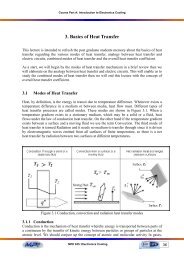
Part B: <strong>Heat</strong> <strong>Transfer</strong> Principals in Electronics Cooling∂Ψu =∂ yAnd∂Ψυ = −∂xSo that the continuity equation may be intrinsically satisfied(<strong>8.</strong>7)(<strong>8.</strong>8)Considering the partial differential equation describing the momentum equation (Equation <strong>8.</strong>2), wemay use the similarity method in order to convert it into an ordinary differential equation.Defining the dependent and independent dimensionless variables ƒ and η, will help us in thisanalytical approach.Ψf (η ) =(<strong>8.</strong>9)u∞vx / u∞(<strong>8.</strong>10)η =y u / vxThe Blausis exact solution is termed a similarity solution, and η is the similarity variable.This terminology is used because, despite growth of the boundary layer with distance x from the leadingedge, the velocity profile u/u ∞ , remains geometrically similar as shown in Figure <strong>8.</strong>4.u y = fun.( )u∞δWhere δ is the boundary layer thickness and usually difficult to measureAssuming this thickness to vary as (ν x / u ∞ ) 1/2 , its follows thatu = fun.(η)u∞Hence the velocity profile is assumed to be uniquely determined by the similarity variable η whichdepends on x and y directions.∞u ∞u ∞δuuFigure <strong>8.</strong>4 the profile u/u ∞ geometrically similarFrom Equations <strong>8.</strong>7 and <strong>8.</strong>8∂Ψu =∂ y∂Ψ ∂η= = u∂η∂ yvxudfdηu∞∞=∞vxu∞dfdη(<strong>8.</strong>11)MPE 635: Electronics Cooling59
Part B: <strong>Heat</strong> <strong>Transfer</strong> Principals in Electronics CoolingAnd∂Ψυ = − = )∂x( vx ∂fu∞v− uu x 2 u xf∞+∂∞∞υ =12vux∞⎛ df⎜η−⎝ dηf⎞⎟⎠(<strong>8.</strong>12)By differentiating the velocity components, it may also be shown that∂ 2u u∞d f= − η(<strong>8.</strong>13)2∂x2xd∂u= u∂ y2∂ u2∂ y∞η2u d f(<strong>8.</strong>14)∞2vx dη2 3u∞d f=(<strong>8.</strong>15)3vx dηSubstituting these equations in the momentum equation, then we obtain32d f d f2 + f = 032dη dη(<strong>8.</strong>16)This is non linear, third-order differential equation, so that we need three boundary conditions to get asolution, these boundary conditions are:At η =0ƒ / ( η) = ƒ( η) =0At η = ∞ƒ / ( η) = u/u ∞ =1The solution of Equation <strong>8.</strong>16 by numerical integration and the results are given in Table <strong>8.</strong>1.At u/u ∞ =0.99 for η =5, substitute in Equation <strong>8.</strong>10δ 5=x Re xThe shear stress can be expressed as⎛ ∂u⎞ ⎛τ ⎟ = ⎜s= ⎜µµ u∞⎝ ∂ y ⎠ y=⎝2u∞d f ⎞⎟2vx dη⎠0 η=0(<strong>8.</strong>17)From the Table <strong>8.</strong>1τ = 0 . 332us∞ρµ ux∞And the wall local shear stress coefficient C ƒ ,is given byMPE 635: Electronics Cooling60
Part B: <strong>Heat</strong> <strong>Transfer</strong> Principals in Electronics CoolingCf=τs1 2∞ρu2=0.664Rex(<strong>8.</strong>18)Table <strong>8.</strong>1: The function ƒ (η) for laminar boundary layer over flat plateη = yudf2u∞ƒ(η)=d fvxdη u2∞dη0 0 0 0.3320.4 0.027 0.133 0.3310.8 0.106 0.265 0.3271.2 0.238 0.394 0.3171.6 0.42 0.517 0.2972 0.65 0.63 0.2672.4 0.922 0.729 0.2282.8 1.231 0.812 0.1843.2 1.569 0.876 0.1393.6 1.93 0.923 0.0984 2.306 0.956 0.0644.4 2.692 0.976 0.0394.8 3.085 0.988 0.0225.2 3.482 0.994 0.0115.6 3.88 0.997 0.0056 4.28 0.999 0.0026.4 4.679 1 0.0016.8 5.079 1 0Example <strong>8.</strong>1: Consider fluid flow at u ∞ =0.3 m/s past a flat plate 0.3 m long. Compute the boundarylayer thickness at the trailing edge for (a) air and (b) water at 20 o C.Solution:Part (a)From air properties table at 20 o Cν =15.267x10 -6 m 2 /s.The trailing edge Reynolds number is(0.3)(0.3)Re = u∞L=5895615.267x10=L−vThe flow is laminar, from Equation <strong>8.</strong>17 the predicted laminar thickness isδ 5= = 0.065x 5895At x = 0.3 mδ = 0.0195 mMPE 635: Electronics Cooling61
Part (b)From saturated water properties table at 20 o C:ν water = 1.0437x10 -6 m 2 /s.The trailing edge Reynolds number isPart B: <strong>Heat</strong> <strong>Transfer</strong> Principals in Electronics Coolingu∞L(0.3)(0.3)Re = =86231.6761.0437Χ10=L−vThis again satisfies the laminar condition the laminar thickness isδ 5== 0.017x 86231.67At x = 0.3 mδ = 0.0051 mSolving the energy equation (Equation <strong>8.</strong>6):Let the dimensionless temperature T∗T −Ts=T −TT∗ = T ∗ (η) , and substitute in energy equation to give this form.∞sand assume similarity solution of the form2 ∗∗d T Pr dT+ f = 02dη 2 dη(<strong>8.</strong>19)Where the variable ƒ depend on the Prandtl number valuesThe appropriate boundary conditions are∗∗T ( 0) = 0And T ( ∞)= 1The solution may be achieved by numerical integration method for 0.6 ≤ Pr < 50∗⎛ dT ⎞It will produce the surface temperature gradient⎜⎟ as the following relation.⎝ dη ⎠η=0If T s >T ∞⎛ ⎞⎜⎟⎝ dη ⎠∗dT =0.332 Pr 1/3Expression for the local heat convection coefficient determined as follow.//∂Tqx= hx( Ts− T∞) = −k∂ y∗− k ∂TT∞− Ts⎛ ∂T⎞h == −(∞)⎜⎟xkTs− T ∂ y Ts− T∞⎝ ∂ y ⎠h x⎛ u∞= k⎜⎝ vx⎞⎟⎠1/ 2η=0∗⎛ ∂T⎞⎜⎟⎝ ∂η⎠η=0y=0MPE 635: Electronics Cooling62
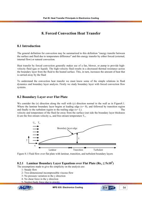
Part B: <strong>Heat</strong> <strong>Transfer</strong> Principals in Electronics CoolingIt follows that the local Nusselt number in this formhxxNux= = .332 Rek1/ 20xPr1 / 3(<strong>8.</strong>20)And the average heat transfer coefficient can be obtained by integration ∴h = 2hxxhxNu1= hx∫xx0xhxx=k= 0.664 Re1 / 2xRe1 / 3(<strong>8.</strong>21)<strong>8.</strong>3 The Thermal Boundary LayerAnalogous to the velocity boundary layer there is a thermal boundary layer adjacent to a heated (orcooled) plate. The temperature of the fluid changes from the surface temperature at the surface to thefree-stream temperature at the edge of the thermal boundary layer as shown in Figure <strong>8.</strong>5.T ∞T ∞ , u ∞T S > T ∞T SFigure <strong>8.</strong>5.Fluid temperature variations inside the thermal boundary layerThe velocity boundary layer thickness depends on the Reynolds number Re X. . But the thermal boundarylayer thickness depends both on Re X and Pr as shown in Figure<strong>8.</strong>6.Temperature boundary layerVelocity boundary layerPr 1yδδ TT SxMPE 635: Electronics Cooling63
Part B: <strong>Heat</strong> <strong>Transfer</strong> Principals in Electronics CoolingFigure <strong>8.</strong>6 thermal boundary layer thicknesses relative to velocity boundary layer thickness at differentPrandtle numberFor laminar flow (Re x < Re cr ):δ 5=x Re xAt Pr ≥ 0.7δδ T1/ 3= Pr(<strong>8.</strong>22)At Pr «1δδ T1/ 2= PrFor turbulent flow (Re x > Re cr ):δx =0.37Re0.2Xδ ≈ δ T(<strong>8.</strong>23)<strong>8.</strong>4 Cooling Air Fans for Electronic EquipmentAir is the most commonly used medium for heat transfer. It is available everywhere on the surface ofthe planet .Air is usually taken directly from the surrounding atmosphere and returned to it. Manydifferent types of fans are available for cooling electronic equipment. These can generally be dividedinto two major types: axial and centrifugal fans. These fans can be driven by various types of electricmotors, single phase, three phase, 60 cycles, 400 cycles, 800 cycle ac/dc, constant speed, variablespeed. The flow rates also vary from 1 cfm to several thousand cfm. When a fan is used for coolingelectronic equipment, the airflow direction can be quite important. The fan can be used to draw airthrough a box or to blow air through a box. A blowing fan system will raise the internal air pressurewithin the box, which will help to keep dust and dirt out of a box that is not well sealed. A blowingsystem will also produce slightly more turbulence, which will improve the heat transfer characteristicswithin the box. However, when an axial flow fan is used in a blowing system, the air may be forced topass over the hot fan motor, which will tend to heat the air as it enters the electronic box, as shown inFigure <strong>8.</strong>7.An exhaust fan system, which draws air through an electronic box, will reduce the internal airpressure within the box. If the box is located in a dusty or dirty area, the dust and dirt will be pulledinto the box through all of the small air gaps if the box is not sealed. In an exhaust system, the coolingair passes through an axial flow fan as the air exits from the box, as shown in Figure <strong>8.</strong><strong>8.</strong> The coolingair entering the electronic box is therefore cooler.Figure <strong>8.</strong>7 Axial flow fan blowing cooling air through a boxMPE 635: Electronics Cooling64
Part B: <strong>Heat</strong> <strong>Transfer</strong> Principals in Electronics CoolingFigure <strong>8.</strong>8 Axial flow fan drawing cooling air through a box<strong>8.</strong>5 Static Pressure and Velocity PressureAirflow through an electronic box is due to a pressure difference between two points in the box, withthe air flowing from the high-pressure side to the low-pressure side. The flow of air will result in astatic pressure and a velocity pressure. Static pressure is the pressure that is exerted on the walls of thecontainer or electronic box, even when there is no flow of air; it is independent of the air velocity.Static pressure can be positive or negative, depending upon whether it is greater or less than theoutside ambient pressure.Velocity pressure is the pressure that forces the air to move through the electronic box at a certainvelocity. The velocity pressure depends upon the velocity of the air and always acts in the direction ofthe airflow. The amount of cooling air flowing through an electronic box will usually determine theamount of heat removed from the box. The higher the air flow rate through the box the higher heatwill be removed. As the airflow through the box increases, however, it requires an even greaterpressure to force the air through the box.Static and velocity pressures can be expressed in lb/in 2 and g/cm 2 . However, these values are usuallyvery small, so that it is often more convenient to express these pressures in terms of the height of acolumn of water. The velocity head (H v) is a convenient reference that is often used to determinepressure drops through electronic boxes. The velocity head can be related to the air flow velocity asfollowWhere:V =V = Velocity of the airg = gravitational accelerationH v = velocity head in centimeter of water2 gH v(<strong>8.</strong>24)The Equation <strong>8.</strong>24 can be modified using standard air with a density of 0.0012 g/cm 3 at 20.5 o C and 1bar, this is shown in Equation <strong>8.</strong>25.V =2(979.6 cm / sec23)(1 g / cm water)(H30.0012 g / cm airVcm water)V = 1277H v( cm water)= cm / sec.(<strong>8.</strong>25)The total head will be the sum of the velocity head and the static head as followH = H + Htvs(<strong>8.</strong>26)MPE 635: Electronics Cooling65
Part B: <strong>Heat</strong> <strong>Transfer</strong> Principals in Electronics CoolingWe have many cases for measurement of the total heads inside the electronic box as shown in theFigures <strong>8.</strong>9, <strong>8.</strong>10, and <strong>8.</strong>11. In case of a pressurized electronic box with no air flows the total pressureequal to the static pressure as shown in Figure <strong>8.</strong>9. While in case of a fan blows air through theelectronic box, the pressure within the box will be slightly higher than the outside air pressure. Avelocity head will now be developed, as shown in Figure <strong>8.</strong>10. But, in case of a fan draws the air throughthe box, the pressure within the box will be slightly lower than the outside air pressure, and the pressurehead characteristics will appear as shown in Figure <strong>8.</strong>11. And the total head is still constant as shownby Equation. <strong>8.</strong>26.Figure <strong>8.</strong>9 a pressurized electronic box with no air flowFigure <strong>8.</strong>10 pressure head characteristics when the fan blows air through an electronic boxFigure <strong>8.</strong>11 pressure head characteristics when the fan draws air through an electronic boxMPE 635: Electronics Cooling66
Part B: <strong>Heat</strong> <strong>Transfer</strong> Principals in Electronics Cooling<strong>8.</strong>6 Fan Performance CurveElectronic boxes that are cooled with the use of fans must be carefully evaluated to make sure the fanwill provide the proper cooling. If the fan is too small for the box, the electronic system may over heatand fail. If the fan is too big for the box, the cooling will be adequate, but the larger fan will be moreexpensive, heavier, and will draw more power.Air flowing through the electronic box will encounter resistance as it enters the different chambers andis forced to make many turns. The flow resistance is approximately proportional to the square of thevelocity, so that it is approximately proportional to the square of the flow rate in cubic feet per minute(cfm). When the static pressure of the air flow through a box is plotted against the air flow rate, the resultwill be a parabolic curve. This curve can be generated by considering the various flow resistances theairflow will encounter as it flows through the box. The method of analysis is to assume several differentflow rates through the box and then to calculate a static pressure drop though the box for each flow rate.This curve is called impedance curve for the electronic box as shown in Figure <strong>8.</strong>12.Once the box flow impedance curve has been developed, it is necessary to examine different fanperformance curves to see how well the fans will match the box. A typical fan performance curve isshown in Figure <strong>8.</strong>13.Figure <strong>8.</strong>12 air flow impedance curve for the electronic boxMPE 635: Electronics Cooling67
Part B: <strong>Heat</strong> <strong>Transfer</strong> Principals in Electronics CoolingFigure <strong>8.</strong>13 fan impedance curveIf the impedance curve for the box is superimposed on the impedance curve for the fan, they willintersect. The point of intersection represents the actual operating point for the system, as shown inFigure <strong>8.</strong>14.Figure <strong>8.</strong>14 intersection of fan and box impedance curves<strong>8.</strong>7 Cabinet Cooling HintsIn addition to selecting a fan, there may be some choice in the location of the fan or fans, andin this regard, the illustration in Figure <strong>8.</strong>15 may prove useful. The following comments shouldalso be kept in mind with regard to fan location:1) Locate components with highest heat dissipation near the enclosure air exits2) Size the enclosure air inlet and exit vents at least as large as the venturi opening of the fanused3) Allow enough free area for air to pass with velocity less than 7 meters/sec4) Avoid hot spots by spot cooling with a small fan5) Locate components with the most critical temperature sensitivity nearest to inlet air toprovide the coolest air flow6) Blow air into cabinet to keep dust out, i.e. pressurize the cabinet7) Use the largest filter possible, in order to reduce pressure drop and keep the system from thedust<strong>8.</strong>8 Design Steps for Fan-Cooled Electronic Box SystemsThe system as shown in Figure <strong>8.</strong>16 must be capable of continuous operation in a 55 °C (131 °F)ambient at sea level condition. The maximum allowable hot spot component surface temperature islimited to 100 °C (212 °F). The system contains seven PCBs, each dissipating 20 watts, for a total powerdissipation of 140 watts. This does not include fan power dissipation.MPE 635: Electronics Cooling68
Part B: <strong>Heat</strong> <strong>Transfer</strong> Principals in Electronics CoolingFigure <strong>8.</strong>15 Cabinet cooling hintsFigure <strong>8.</strong>16 plan view of fan-cooled electronic boxMPE 635: Electronics Cooling69
Part B: <strong>Heat</strong> <strong>Transfer</strong> Principals in Electronics CoolingThe flow area at the partitions designed on the drawing are as followsInlet to fan is an annuals (dimensions are in mm)482890 o turn and transition from a round section at the fan to an oval section7410013Contraction and transition to rectangular section a rectangle 8 x 125 mm2Plenum entrance to a PCB duct rectangle each 1.5 x 155 mm2PCB channel duct as shown in the following drawingRectangle each 2.5 x 230 mm 2 (0.1 x 9 in 2 )Design procedures:Two fans are available for cooling the box: Fan A is three phase 15500 rpm that has a 25 Watts motor.Fan B is single phase, with an 18 Watts motor that operates at 11000 rpm at sea level. The box must beexamined in two phases to ensure the integrity of the complete design. In phase 1, the thermaldesign of the box is examined, with the proposed fan, to make sure the component hot spot temperatureof 100°C (212°F) is not exceeded. In phase 2, the electronic chassis airflow impedance curve isdeveloped and matched with several fans, to make sure there is sufficient cooling air available for thesystem.MPE 635: Electronics Cooling70
Part B: <strong>Heat</strong> <strong>Transfer</strong> Principals in Electronics CoolingPhase 1: Electronic box thermal design:To be on the safe side, base the calculation on the use of larger, 25 W motor, Fan AThe total energy to be dissipated would then beq = 140 + 25 = 165 WAir required for cooling is• qm =c t − t )p(a, o a,iPast experience with air-cooled electronic systems has shown that satisfactory thermal performance canbe obtained if the cooling air exit temperature from the electronic chassis does not exceed 70 °C (160°F), so that assume exit air temperature t a,o = 70 °CFrom the air property table at mean temperature t m = (70+55)/2 = 62.5 °Cρ = 1.052 kg/m 3ν = 19.23 x10 -6 m 2 /sPr = 0.7C p = 1008 J/kg.Kk = 0.0289 W/m.. o CAir required for cooling is• 165m == 0.01091kg/s1008(70 − 55)By calculating the heat transfer coefficient between the air and PCB ' s and, hence, the temperature riseof the PCB ' s above the ambient air. For this purpose we calculate the Reynolds' numberVDHRe =v4A4 x 9 x0.1Q DH= = = 0.197 in = 0.005 mP 2(9 + 0.1)andV =•m0.01091=ρ A 1.052 (7x9x0.1)x(0.0254)2.55 x 0.005∴ Re == 663-619.23 x102= 2.55 m / sThe heat transfer coefficient for laminar flow through ducts is shown in the following relationh DkH= NuDh = 24.2 W/m⎛ Re Pr ⎞= 1.86⎜⎟/⎝ L DH⎠⎛ 663 x0.7x0.005⎞= 1.86⎜8 0.0254⎟⎝ x ⎠2.K1/ 31/ 3= 4.19The total heat transfer isq = h Seff∆thMPE 635: Electronics Cooling71
Part B: <strong>Heat</strong> <strong>Transfer</strong> Principals in Electronics CoolingActually, the back surface of a PCB is not available for heat transfer; the practice is to assume 30 percentonly available for this purpose22S = 7 x1.3x8x 9 (0.0254) = 0.423 meff∆th= 165/ 24.2 x0.423= 16.1Therefore, maximum component surface temperaturet max = t a,o + ∆t h = 70 + 16.1 = 86.1 o CThis is acceptable surface temperature since it is less than 100 °CoCPhase 2: Electronic chassis air flow impedance curve:The air flow conditions are examined at six different points in the chaises, where the maximum staticpressure losses are expected to occur, as shown in Figure <strong>8.</strong>16. These static pressure losses are itemizedas follow:1- Air inlet to fan2- 90 o turn and transition to an oval section3- Concentration and transition to a rectangular section4- Plenum entrance to PCB duct5- Flow through PCB channel duct6- Exhaust from PCB duct and chaisesThe following table gives the ratio between static head loss to velocity head at the different positionsPosition numberH s / H v1 12 0.93 0.44 25 16 1The flow areas at each position are:π 2 2 π22A1 = do− di= 0.048 − 0.028 = 1.194 x104422Position 2: A2= 0.026x0.074+ π x0.013= 2. 455 m−32Position 3: A3 = 0.008x0.125= 1 x10m−32Position 4: A4 = 0.0015x0.155x7slots= 1.628 x10m−32Position 5: A5 = 0.0025x0.23x7= 4.025 x10m−32Position 1: ( ) ( )Position 6:A−325= A6= 4.025x10mmThe following table gives velocity, velocity heads at each position at 10 cfm (0.283 m 3 /min)MPE 635: Electronics Cooling72
Part B: <strong>Heat</strong> <strong>Transfer</strong> Principals in Electronics CoolingPosition V (cm/s.) H v (cm H 2 O)1 400 0.0982 376 0.0873 488 0.1464 290 0.05165 116 0.00826 116 0.0082Performing the test under different cfm air flow: let the flow rate also at 20 cfm, and 30 cfmThe losses for each another flow calculated fromV •H = (H s / H v ) H v, 10 ( ) 10The following table gives the static pressure loss in (cm H 2 O) at 10 cfm, 20 cfm, and 30 cfmPosition 10 cfm 20 cfm 30 cfm1 0.098 0.392 0.8822 0.086 0.345 0.7773 0.0729 0.292 0.6574 0.103 0.411 0.9275 0.0082 0.0325 0.07316 0.0082 0.0325 0.0731Total 0.3761 1.5 3.3892Then drawing the chassis air flow impedance curve at different fan curves as shown belowThe minimum flow rate required for this system is•• m 0.0109133V = = = 0.01 m / s = 10370.7 cm / sρ 1.052MPE 635: Electronics Cooling73
Part B: <strong>Heat</strong> <strong>Transfer</strong> Principals in Electronics CoolingFrom the impedance curve it shows:The flow rate supplied by fans A is•3V = 30cfm = 14157 cm / sThe flow rate supplied by fans B is•3V = 23cfm = 10854 cm / sSo that both fans A and B can supply more than the minimum required flow rate, either fan will beacceptable.MPE 635: Electronics Cooling74