1600 Series In-Line Pump - Taco-Hvac
1600 Series In-Line Pump - Taco-Hvac
1600 Series In-Line Pump - Taco-Hvac
- No tags were found...

Create successful ePaper yourself
Turn your PDF publications into a flip-book with our unique Google optimized e-Paper software.
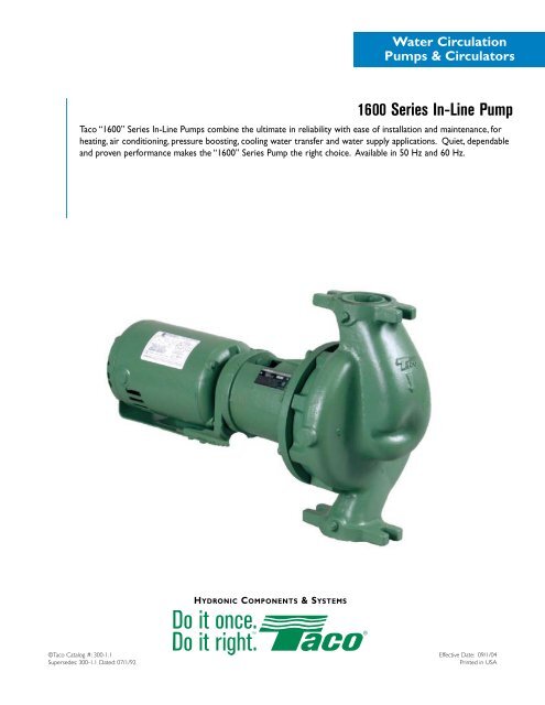
Water Circulation<strong>Pump</strong>s & Circulators<strong>1600</strong> <strong>Series</strong> <strong>In</strong>-<strong>Line</strong> <strong>Pump</strong><strong>Taco</strong> “<strong>1600</strong>” <strong>Series</strong> <strong>In</strong>-<strong>Line</strong> <strong>Pump</strong>s combine the ultimate in reliability with ease of installation and maintenance, forheating, air conditioning, pressure boosting, cooling water transfer and water supply applications. Quiet, dependableand proven performance makes the “<strong>1600</strong>” <strong>Series</strong> <strong>Pump</strong> the right choice. Available in 50 Hz and 60 Hz.Hydronic Components & Systems©<strong>Taco</strong> Catalog #: 300-1.1Supersedes: 300-1.1 Dated: 07/1/92Effective Date: 09/1/04Printed in USA
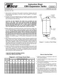
2.Features & BenefitsQuiet, dependablepower and provenperformance.<strong>1600</strong> <strong>Series</strong> <strong>In</strong>-<strong>Line</strong> pumps meet the latestindustry standards for hydraulic performanceand reliability. Each is backed by <strong>Taco</strong><strong>In</strong>c. a worldwide leader in the design andmanufacture of heating and cooling equipmentfor more than eight decades. <strong>Taco</strong> “<strong>1600</strong>”<strong>Series</strong> <strong>In</strong>-<strong>Line</strong> pumps are available in 15models ranging in size from 1 1⁄2" X 1 1⁄2"to 2" X 2" with a flow range from 10 to 235GPM and head capacities up to 68 feet.Rear pull out designallows servicing of thepump without disturbingthe piping.Replaceable "cooler running"bearing cartridge extendsbearing life and permanentlysealed grease lubricated ballbearings makes it virtuallymaintenance free.<strong>Taco</strong> “<strong>1600</strong>” <strong>Series</strong> <strong>In</strong>-<strong>Line</strong> pumps utilize anexclusive replaceable, cooler running bearingcartridge design. This unique design isolatesthe bearings from the effects of system fluidtemperatures which greatly extends bearinglife. The cartridge design incorporatespermanently sealed grease lubricated ballbearings making it virtually maintenance free.All “<strong>1600</strong>” series <strong>In</strong>-<strong>Line</strong> <strong>Pump</strong>s are furnishedwith ceramic seals (standard) in order to meeta wide range of application requirements. Themechanical seal is an innovative “unitized”design which combines all of the componentsof the rotating element (spring, retainer,bellows and carbon) into one assembly makingseal replacement quick and easy.The standardized cartridge design simplifiesmaintenance with minimal parts requirements,one size cartridge and mechanical seal toservice the entire product line.Exceptionally quiet,smooth runningresilient mountedmotors.Flexible coupler absorbs shock,vibration, and misalignment thatcould be transmitted to the cartridgeand motor bearings while alsoisolating and preventing any motorrelated noise or vibrations frombeing transmitted to the system.
3.Standard ceramic seal meets the demands of awide range of application requirements, and thenew "unitized" design facilitates quick and easyreplacement simplifying maintenance.1/4 NPT pressure tappings on suctionand discharge connections.Replaceable corrosion resistant shaft sleeveincorporates a "built in" slinger to deflect wateraway from the bearing cartridge in the event ofa seal leak.Companion flanges included.
Commercial HydronicApplication <strong>In</strong>formation4.Useful DefinitionsFlow is a volume measure to establish pump capacity perunit of time, usually as GPM.Head is a pressure measurement represented by how highthe pump can lift a column of liquid, usually in feet. Toconvert the popular pressure expression P.S.I. to feet ofwater, multiply P.S.I. X 2.31.Horsepower (H.P.) is the amount of power available todrive the pump.Brake Horsepower (BHP) is the amount of powerrequired to drive the pump.Net Positive Suction Head Required (NPSHR) is apressure measure – in absolute units – expressed in feet,and indicates the pressure required at the pump suctionto prevent cavitation. Reducing the pressure at the pumpflange below the vapor pressure of the liquid can causeformation of vapor pockets in the impeller passes. Thiscondition (cavitation) will interfere with pump performance,and is usually accompanied by noise as the vapor pocketscollapse. NPSHR can be thought of as the amount ofpressure in excess of vapor pressure required to preventthe formation of vapor pockets.Net Positive Suction Head Available (NPSHR) is thepressure available at the pump suction flange. If NPSHA isless the NPSHR, cavitation problems should be expected.<strong>Pump</strong> efficiency represents the portion of brakehorsepower converted into useful work. <strong>Pump</strong> efficiency,along with flow, head, and liquid specific gravity affect thepower required to drive the pump. The more efficient thepump, the less power required to drive it.Shut-Off Head is the head developed by a pump at zeroflow.Static Head is the pressure at the pump discharge whichthe pump must overcome before it can produce flow. Statichead is a difference in elevation and can be computed for avariety of conditions surrounding a pump installation.System Resistance is the pressure on the pumpdischarge resulting from the resistance to flow created byfriction between the fluid and the piping system. This valuewill vary with flow rate.Suction Pressure is the pressure observed at the pumpsuction connection. This may be a positive pressure or anegative pressure.Discharge Pressure is the pressure at the dischargeconnection. This will always be a positive pressure.Differential Pressure is the algebraic difference betweenthe discharge and suction pressures. This value representspump head.Service Factor is the reserve power available from anelectric motor when operating under normal conditions.System Curve is a graphical representation of the hydrauliccharacteristics of a piping system. When the pumpperformance curve is laid over the system curve, theintersection indicates the flow and head pressure of thepump when coupled to the hydraulic system.Constant Speed is the RPM of a pump upon which apublished pump curve is based.Specific Gravity (S.G.) is the relative weight of a liquidwhen compared with water (water = 1.0 S.G.)R.P.M. is the rotational speed of a pump.
JSA/MS 2-18-02 PC-2066 RevA ECN106275.Part I – FundamentalsA centrifugal pump operated at constant speed deliversany capacity from zero to maximum depending on the head,design and suction conditions. <strong>Pump</strong> performance is mostcommonly shown by means of plotted curves which aregraphical representations of a pump’s performancecharacteristics. <strong>Pump</strong> curves present the average resultsobtained from testing several pumps of the same designunder standardized test conditions. For a single familyresidential application, considerations other than flow andhead are of relatively little economic or functionalimportance, since the total load is small and the equipmentused is relatively standardized. For many smaller circulators,only the flow and pressure produced are represented onthe performance curve (Fig. 1-1).<strong>Pump</strong> performance curves show this interrelation of pumphead, flow and efficiency for a specific impeller diameter andcasing size. Since impellers of more than one diameter canusually be fitted in a given pump casing, pump curves showthe performance of a given pump with impellers of variousdiameters. Often, a complete line of pumps of one designis available and a plot called a composite or quick selectioncurve can be used, to give a complete picture of theavailable head and flow for a given pump line (Fig. 1-3).Fig. 1-1For larger and more complex buildings and systems,economic and functional considerations are more critical,and performance curves must relate the hydraulic efficiency,the power required, the shaft speed, and the net positivesuction head required in addition to the flow and pressureproduced (Fig. 1-2).HEAD IN FEET7560453015L/SEC7.50"(191mm)7.00"(178mm)6.50"(165mm)6.00"(152mm)5.50"(140mm)5 10 15CURVES BASED ON CLEAR WATERWITH SPECIFIC GRAVITY OF 1.0REQUIRED NPSH000 75 150 225 300 375 450 525 600FLOW IN GALLONS PER MINUTEFig. 1-250%Model 3007 1760 RPMFI & CI <strong>Series</strong> AUGUST 27, 200155%60%65%70%75%77%2HP(1.5KW)3HP(2.2KW)Curve no. 2066Min. Imp. Dia. 5.50"Size 4 X 3 X 7.020 25 30 3579%77%75%70%65%5HP(3.7KW)60%55%50%7.5HP(5.6KW)FEET108642020105NPSHHEAD IN METERS2001005003024181260KPaHEAD IN KILOPASCALSFig. 1-3Such charts normally give flow, head and pump size only,and the specific performance curve must then be referredto for impeller diameter, efficiency, and other details. Formost applications in our industry, pump curves are basedon clear water with a specific gravity of 1.0.Part II – The System CurveUnderstanding a system curve, sometimes called a systemhead curve, is important because conditions in larger, morecomplex piping systems vary as a result of eithercontrollable or uncontrollable changes. A pump canoperate at any point of rating on its performance curve,depending on the actual total head of a particular system.Partially closing a valve in the pump discharge or changingthe size or length of pipes are changes in system conditionsthat will alter the shape of a system curve and, in turn,affect pump flow. Each pump model has a definite capacitycurve for a given impeller diameter and speed. Developinga system curve provides the means to determine at whatpoint on that curve a pump will operate when used in aparticular piping system.
Commercial HydronicApplication <strong>In</strong>formation6.Pipes, valves and fittings create resistance to flow orfriction head. Developing the data to plot a system curvefor a closed Hydronic system under pressure requirescalculation of the total of these friction head losses.Friction tables are readily available that provide frictionloss data for pipe, valves and fittings. These tablesusually express the losses in terms of the equivalent lengthof straight pipe of the same size as the valve or fitting.Once the total system friction is determined, a plot can bemade because this friction varies roughly as the square of theliquid flow in the system. This plot represents the SYSTEMCURVE. By laying the system curve over the pump performancecurve, the pump flow can be determined (Fig. 2–1).flow capacity. Opening the valve has the opposite effect.Working the system curve against the pump performancecurve for different total resistance possibilities provides thesystem designer important information with which to makepump and motor selection decisions for each system. Asystem curve is also an effective tool in analyzing systemperformance problems and choosing appropriate correctiveaction.<strong>In</strong> an open Hydronic system, it may be necessary to addhead to raise the liquid from a lower level to a higher level.Called static or elevation head, this amount is added to thefriction head to determine the total system head curve.Fig. 2–3 illustrates a system curve developed by addingstatic head to the friction head resistance.Fig. 2-11Care must be taken that both pump head and frictionare expressed in feet and that both are plotted on thesame graph. The system curve will intersect the pumpperformance curve at the flow rate of the pump becausethis is the point at which the pump head is equal to therequired system head for the same flow.Fig. 2–2 illustrates the use of a discharge valve to changethe system head to vary pump flow. Partially closing thevalve shifts the operating point to a higher head or lowerFig. 2-3Part III – Stable Curves, UnstableCurves And Parallel <strong>Pump</strong>ingOne of the ways in which the multitude of possibleperformance curve shapes of centrifugal pumps can besubdivided is as stable and unstable. The head of a stablecurve is highest at zero flow (shutoff) and decreases as theflow increases. This is illustrated by the curve of <strong>Pump</strong> 2 inFig. 3 – 1.Fig. 2-22
7.So-called unstable curves are those with maximum headnot at zero, but at 5 to 25 percent of maximum flow, asshown by the curve for <strong>Pump</strong> 1 in Fig. 3 – 1.The term unstable, though commonly used, is ratherunfortunate terminology in that it suggests unstable pumpperformance. Neither term refers to operating characteristic,however. Each is strictly a designation for a particular shapeof curve. Both stable and unstable curves have advantagesand disadvantages in design and application. It is left to thediscretion of the designer to determine the shape of hiscurve.Single <strong>Pump</strong> <strong>In</strong> OpenSystem With Static Head<strong>In</strong> an open system with static head, the resistance curveoriginates at zero flow and at the static head to beovercome. The flow is again given by the intersection ofsystem resistance and pump curves as illustrated for astable curve in Fig. 3–2.2<strong>In</strong> a vast majority of installations, whether the pump curveis stable or unstable is relatively unimportant, as the followingexamples of typical applications show.Single <strong>Pump</strong> <strong>In</strong> Closed System<strong>In</strong> a closed system, such as a Hydronic heating or coolingsystem, the function of the pump is to circulate the samequantity of fluid over and over again. Primary interest is inproviding flow rate. No static head or lifting of fluid fromone level to another takes place.All system resistance curves originate at zero flow any head.Any pump, no matter how large or small, will produce someflow in a closed system.For a given system resistance curve, the flow produced by anypump is determined by the intersection of the pump curvewith the system resistance curve since only at this point isoperating equilibrium possible. For each combination ofsystem and pump, one and only one such intersection exists.Consequently, whether a pump curve is stable or unstable isof no consequence. This is illustrated in Fig. 3 –1.Fig. 3-23 2It has been said that in an open system with static head acondition could exist where an unstable curve could causethe flow to “hunt” back and forth between two points sincethe system resistance curve intersects the pump curvetwice, as shown in Fig. 3–3. The fallacy of this reasoning lies,in the fact that the pump used for the system in Fig. 3–3already represents an improper selection in that it can neverdeliver any fluid at all. The shutoff head is lower than thestatic head. The explanation for this can be found in themanner in which a centrifugal pump develops its full pressurewhen the motor is started. The very important fact toremember here is that the shutoff head of the pump musttheoretically always be at least equal to the static head.3Fig. 3-1Fig. 3-33 3
Commercial HydronicApplication <strong>In</strong>formation8.From a practical point of view, the shutoff head should be5 to 10 percent higher than the static head because theslightest reduction in pump head (such as that caused bypossible impeller erosion or lower than anticipated motorspeed or voltage) would again cause shutoff head to belower than static head. If the pump is properly selected,there will be only one resistance curve intersection withthe pump curve and definite, unchanging flow will beestablished, as shown in Fig. 3–4.4If a system with fixed resistance (no throttling devices suchas modulating valves) is designed so that its head, with allpumps operating (maximum flow) is less than the shutoffhead of any individual pump, the different pumps may beoperated singly or in any combination, and any startingsequence will work. Fig. 3–5 shows and example consistingof two dissimilar unstable pumps operating on an opensystem with static head.5Fig. 3-43 4<strong>Pump</strong>s Operating <strong>In</strong> Parallel<strong>In</strong> more complex piping systems, two or more pumps maybe arranged for parallel or series operation to meet a widerange of demand in the most economical manner. Whendemand drops, one or more pumps can be shut down,allowing the remaining pumps to operate at peak efficiency.<strong>Pump</strong>s operating in Parallel give multiple flow capacityagainst a common head. When pumps operate in series,performance is determined by adding heads at the sameflow capacity. <strong>Pump</strong>s to be arranged in series or parallelrequire the use of a system curve in conjunction with thecomposite pump performance curves to evaluate theirPerformance under various conditions.It is sometimes heard that for multiple pumping theindividual pumps used must be stable performance curves.Correctly designed installations will give trouble-freeservice with either type of curve, however.Fig. 3-53 5It is also important to realize that stable curves do notguarantee successful parallel pumping by the mere fact thatthey are stable. Fig. 3–6 illustrates such a case. Twodissimilar pumps with stable curves are installed in a closedsystem with variable resistance (throttling may be affectedby manually operated valves, for example).With both pumps running, no benefit would be obtained from<strong>Pump</strong> 1 with the system resistance set to go through A, orany point between 0 and 100 GPM, for that matter. <strong>In</strong> fact,within that range, fluid from <strong>Pump</strong> 2 would flow backwardthrough <strong>Pump</strong> 1 in spite of its running, because pressureavailable from <strong>Pump</strong> 2 would flow backward through <strong>Pump</strong> 1in spite of its running, because pressure available from <strong>Pump</strong> 2is greater than that developed by <strong>Pump</strong> 1.6The important thing to remember is that additional pumpscan be started up only when their shutoff heads are higherthan the head developed by the pumps already running.Fig. 3-63 6
9.<strong>In</strong> other words, <strong>Pump</strong> 2 overpowers <strong>Pump</strong> 1. For thisreason, with <strong>Pump</strong> 2 running alone, <strong>Pump</strong> 1 should not bestarted unless <strong>Pump</strong> 2 operates to the right of the pointwhere the curve of <strong>Pump</strong> 2 and the curve of <strong>Pump</strong>s 1 and2 diverge (100 GPM) in Fig.3–6.Parallel pumping is often an excellent way to obtainoptimum operating conditions and to save energy. To besuccessful, however, systems and operating conditions mustbe understood. This applies to both stable and unstablepump curves.Part IV – NPSH And <strong>Pump</strong> CavitationThe net positive suction head (NPSH) is an expression ofthe minimum suction conditions required to preventcavitation in a pump. NPSH can be thought of as the headcorresponding to the difference between the actual absolutepressure at the inlet to the pump impeller and the fluidvapor pressure. An incorrect determination of NPSH canlead to reduced pump capacity and efficiency, severeoperating problems and cavitation damage.It is helpful to define separately two basic NPSH considerations;required NPSH (NPSHR) and available (NPSHA).The required or minimum NPSH is dependent on the designof a particular pump and is determined by the manufacturer’stesting of each pump model. The pump manufacturer can plotthis required NPSH for a given pump model on performancecurve and this value, expressed as feet of the liquid handled,is the pressure required to force a given flow through thesuction piping into the impeller eye of the pump. RequiredNPSH can also be defined as the amount of pressure inexcess of the vapor pressure required by a particular pumpmodel to prevent the formation of vapor pockets orcavitation. Required NPSH, then, varies from one pumpmanufacturer to the next and from one manufacturer’s modelto another. The required NPSH for a particular pump modelvaries with capacity and rapidly increases in high capacities.The available NPSH, on the other hand, is dependent on thepiping system design as well as the actual location of thepump in that system. The NPSH available as a function ofsystem piping design must always be greater than the NPSHrequired by the pump in that system. The NPSH availableas a function of system piping design must always be greaterthan the NPSH required by the pump in that system or noiseand cavitation will result. The available NPSH can be alteredto satisfy the NPSH required by the pump, if changes in thepiping liquid supply level, etc., can be made. <strong>In</strong>creasing theavailable NPSH provides a safety margin against the potentialfor cavitation. The available NPSH is calculated by using theformula:NPSHA = ha +/- hs - hvpa – hfwhere:ha = atmospheric pressure in feet absolutehs “+” = suction head or positive pressure in a closedsystem, expressed in feet gaugehs “-” = suction lift or negative pressure in a closed system,expressed in feet gaugehvpa = vapor pressure of the fluid in feet absolutehf = pipe friction in feet between pump suctionand suction reference point.Cavitation can be defined as the formation and subsequentcollapse of vapor pockets in a liquid. Cavitation in a centrifugalpump begins to occur when the suction head is insufficientto maintain pressures above the vapor pressure. As the inletpressure approaches the flash point, vapor pockets form bubbleson the underside of the impeller vane which collapse as theymove into the high-pressure area along the outer edge of theimpeller. Severe cavitation can cause pitting of the impellersurface and noise levels audible outside the pump.The <strong>Taco</strong> pump performance curve below (Fig. 4–1) includesa plot of the required NPSH for a <strong>Taco</strong> Model 1506. If apump capacity of 105 GPM is used as an example capacityrequirement, reading vertically from that GPM rate shows arequired NPSH of 4 feet. An available system NPSH greaterthan 4 feet would, therefore, be necessary to ensuresatisfactory pump performance and operation.HEAD IN FEET5040302010L/SEC6.25"(159mm)5.75"(146mm)5.25"(133mm)4.75"(121mm)4.25"(108mm)Curve no. 2015Min. Imp. Dia. 4.25"Size 2 x 1.5 x 624 6 8 101 3 5 7 9 1100 00 25 50 75 100 125 150 175 200FLOW IN GALLONS PER MINUTEMS 2-18-02 PC-2015 RevB ECN10627Fig. 4-142%46%CURVES BASED ON CLEAR WATERWITH SPECIFIC GRAVITY OF 1.0Model 1506CI & FI <strong>Series</strong>54%.33HP(.25KW)57%60%63%1760 RPMAugust 9, 2001REQUIRED NPSH64.5%63%60%.5HP(.37KW)57%54%.75HP(.56KW)46%42%1HP(.75KW)1.5HP(1.1KW)FEET2 60 012111098765432 201KPa8 246 184 12HEAD IN METERSNPSH1201101009080706050403010HEAD IN KILOPASCALS
10.Commercial HydronicApplication <strong>In</strong>formationFeaturesBenefitsRugged Casing Design The “<strong>1600</strong>” <strong>Series</strong> has a maximum operating pressure of 175psi, and a maximumoperating temperature of 300°F. The “<strong>1600</strong>” <strong>Series</strong> is available in cast-iron bronze fittedconstruction or all bronze construction.Cartridge Assembly Replaceable "cooler running" bearing cartridge extends bearing life, and with permanentlysealed greased lubricated ball bearings it is virtually maintenance free.Pressure TappingsPressure tappings allow for differential pressure readings to be taken across the pump.One Piece Enclosed Impeller Dynamically balanced cast bronze impeller assures long life and higher pump efficiencies.Cupro-Nickel Shaft Sleeve Non corrosive shaft sleeve protects the shaft by preventing contact between the shaft andsystem fluid eliminating the need for more expensive corrosion resistant shaft materials.Standard Mechanical Seal “<strong>1600</strong>” <strong>Series</strong> <strong>In</strong>-<strong>Line</strong> pumps utilize a “unitized” seal design which facilitates quick and easyreplacement. Available in ceramic (standard) or the new “Sealide C” (for more aggressivesystem fluids) ensures the flexibility to meet a wide range of application requirements. Onesize seal fits all models.Flexible CouplerFlexible coupler absorbs shock, vibration and misalignment that could be transmitted to thecartridge and motor bearings while also isolating and preventing any motor related noise orvibrations from being transmitted to the system.Resilient Mounted Motor Resilient mounted motor insures quiet reliable vibration free operation of the pump.Parts FlexibilitySuperior parts flexibility: one cartridge, one seal, and two motor frames fit all pump models.Factory TestedAll “<strong>1600</strong>” series pumps are factory tested, and are built in accordance with Hydraulic<strong>In</strong>stitute Standards.Operating SpecificationsDescription Standard OptionalPressure175psi Maximum Operating Pressure(125psi Flanges Standard)Temperature Mechanical Seal 250°F 300°FMotors Nema Standard, Resilient Mounted Special EnclosuresCoupler<strong>Pump</strong> BearingsPressure Tappings<strong>Pump</strong> FlangesFlexible TypeBall Bearing Replaceable CartridgeTapped Suction & Discharge PortsProvided as StandardAvailable with the <strong>Pump</strong>
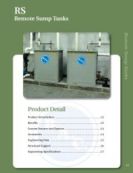
11.Pressure Temperature Ratings<strong>1600</strong> <strong>Series</strong> Performance Field 1450 RPM 50 Hz Curves also available on <strong>Taco</strong>Net.<strong>1600</strong> <strong>Series</strong> Performance Field 1750 RPM 60 Hz Curves also available on <strong>Taco</strong>Net.
ApplicationsLoadMatch SystemsAir Conditioning SystemsRecirculationBooster ServiceHeating SystemsLaundry EquipmentCooling TowersGolf CoursesDry Cleaning PlantsLivestock WateringBottle WashersLawn SprinklersMaterials of ConstructionDescription Standard OptionalCasing Cast Iron BronzeImpellerCast BronzeShaft Hardened Alloy Steel S/S (416)Shaft SleeveCupro-NickelBracket Cast Iron Cast Iron withS/S Face Plate<strong>Pump</strong> DimensionsModel No.Custom Stock<strong>1600</strong>1611 1610161516191635164116121614161616301632163416361638FlangeSize1-1/2 (38)1-1/2 (38)2 (51)2 (51)2 (51)1/4* (.19)1/3 (.25)1/2 (.37)1/3 (.25)1/2 (.37)3/4 (.56)1 (.75)3/4 (.56)1 (.75)1-1/2 (1.1)2 (1.5)1/2 (.37)3/4 (.56)1 (.75)1-1/2 (1.1)1-1/2 (1.1)2 (1.5)3 (2.37)Power60Hz HP(KW) 50Hz HP(KW) A B C D1/6 (.17)1/4* (.19)1/3 (.25)1/4* (.19)1/3 (.25)1/2 (.37)3/4 (.56)1/2 (.37)3/4 (.56)1 (.75)1-1/2 (1.1)1/3 (.25)1/2 (.37)3/4 (.56)1 (.75)1 (.75)1 1/2 (1.1)2 (1.5)3 (76)3 (76)3 (76)3-1/8 (79)3-1/8 (79)3-1/8 (79)3-1/8 (79)3 (76)3 (76)3 (76)3 (76)3-1/2 (89)3-1/2 (89)3-1/2 (89)3-1/2 (89)3-5/8 (92)3-5/8 (92)3-5/8 (92)16-1/2 (419)16-1/2 (419)17.00 (432)18 (457)18-1/2 (470)19 (483)19-1/2 (495)18-1/2 (470)19 (483)21 (533)23 (584)18 (457)18-1/2 (470)19 (483)21 (533)21 (533)23 (584)24 (610)Dimensions10-1/4 (260)13-1/2 (343)14-1/2 (368)13-1/2 (343)16-1/2 (419)12-7/8 (327)16-1/8 (410)17-3/8 (441)16-1/8 (410)19-1/2 (495)• English dimensions are in inches. Metric dimensions are in millimeters.• Do not use for construction purposes unless certified.• Metric data is presented in ( ).* 1/4 HP AVAILABLE IN 1 PHASE ONLY.Hydronic Components & Systems<strong>Taco</strong> <strong>In</strong>c., 1160 Cranston Street, Cranston, RI 02920 / (401) 942-8000 / Fax (401) 942-2360<strong>Taco</strong> (Canada) Ltd., 6180 Ordan Drive, Mississauga, Ontario L5T 2B3 / (905) 564-9422 / Fax (905) 564-9436www.taco-hvac.com