Cercon ceram kiss - DENTSPLY Prosthetics
Cercon ceram kiss - DENTSPLY Prosthetics
Cercon ceram kiss - DENTSPLY Prosthetics
- No tags were found...

You also want an ePaper? Increase the reach of your titles
YUMPU automatically turns print PDFs into web optimized ePapers that Google loves.
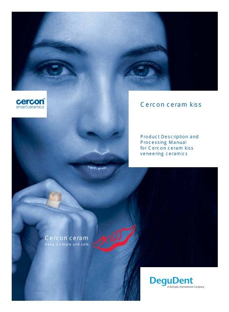
<strong>Cercon</strong> <strong>ceram</strong> <strong>kiss</strong>Product Description andProcessing Manualfor <strong>Cercon</strong> <strong>ceram</strong> <strong>kiss</strong>veneering <strong>ceram</strong>ics<strong>Cercon</strong> <strong>ceram</strong>Keep it simple and safe.
2 IndicationsGeneral NotesLast modified: November 2009<strong>Cercon</strong> ® <strong>ceram</strong> <strong>kiss</strong>0124Purpose■ <strong>Cercon</strong> <strong>ceram</strong> <strong>kiss</strong> is a <strong>ceram</strong>ic veneeringmaterial developed specifically and exclusivelyfor veneering zirconia (Y-TZP) crowns andbridges with a coefficient of thermal expansionof 10.5 µm/m·K (25–500 °C), preferably madeof <strong>Cercon</strong> base.■ <strong>Cercon</strong> <strong>ceram</strong> <strong>kiss</strong> is also suitable for veneer -ing zirconia frameworks overpressed with<strong>Cercon</strong> <strong>ceram</strong> press.■ For dental use only.Contraindications■ <strong>Cercon</strong> <strong>ceram</strong> <strong>kiss</strong> is not suitable for veneeringtitanium or other metal frameworks.■ <strong>Cercon</strong> <strong>ceram</strong> <strong>kiss</strong> is not compatible with anyother veneering <strong>ceram</strong>ics.■ <strong>Cercon</strong> <strong>ceram</strong> <strong>kiss</strong> is contraindicated in brux -ism or other types of parafunction.■ In addition, <strong>Cercon</strong> <strong>ceram</strong> <strong>kiss</strong> is contrain di -cated in situations where the interocclusaldimension is insufficient.Technical specifications■ CTE dentine: 9.2 µm/m·K (25–500 °C)■ Dental <strong>ceram</strong>ic material: Type 1,Class 2– 8 according to DIN EN ISO 6872Release date: February 2005<strong>Cercon</strong> ® <strong>ceram</strong> press0124General instructions on processing<strong>Cercon</strong> <strong>ceram</strong> press■ For information on indications for use, contraindications,warnings, precautions, adversereactions, technical data, transport and storageconditions, explanations of symbols onthe product labels and combinable liquids,please consult the Instructions for Use for<strong>Cercon</strong> <strong>ceram</strong> press.■ For firing recommendations, please refer tothe Instructions for Use of <strong>Cercon</strong> <strong>ceram</strong>press.Precautionary Notes for Medical ProductsAdverse effects and interactionsWe are not aware of any risks or adverse effectsrelated to <strong>Cercon</strong> <strong>ceram</strong> <strong>kiss</strong> veneering <strong>ceram</strong>icsor <strong>Cercon</strong> <strong>ceram</strong> press pressable <strong>ceram</strong>ics. Ifproperly processed and used, adverse effects ofthese medical products will be highly unlikely.However, reactions of the immune system (suchas allergies) or localized paraesthesia (such as anirritating taste or irritation of the oral mucosa) cannotbe completely excluded in principle. Shouldyou hear or be informed of any adverse effects –even when doubtful – we would like to requestnotification. In patient hypersensitivity to <strong>Cercon</strong><strong>ceram</strong> <strong>kiss</strong> veneering <strong>ceram</strong>ics or <strong>Cercon</strong> <strong>ceram</strong>press pressable <strong>ceram</strong>ics or one of their ingredients,this medical product may not be used oronly under the particular scrutiny of the dentistor physician in charge. Known cross-reactionsor interactions of this medical product with othermedical products or material already presentin the oral environment must be taken into consideration by the dentist or physician in chargewhen selecting this medical product.Notify the dentist or physician in charge of allfactors described above if you use this medicalproduct for a custom construction.When working with these materials, make sureto comply with the Instructions for Use and thepertinent Material Safety Data Sheets (MSDS).Safety notes■ Do not inhale dust particles during grinding.Transport and storage■ Liquids: Store containers tightly closed attemperatures above 10 °C.10 °C Lower temperature limit■ Protect powders and pellets from moisture.Keep drySymbols on product labelsREF Catalogue numberLOT Batch codeUse byAttention, see Instructions for UseDo not re-use.Consult instructions for useCombinable liquids■ Paste opaque:Fluid Paste Opaque■ MarginsDucera ® Liquid Quick■ Dentines/incisals, etc.:Ducera ® Liquid BlendDucera ® Liquid SDDucera ® Liquid Form■ Paints/glazes:Ducera ® Liquid Stain improved■ IsolationDucera ® Sep Isolating Fluid
Contents 32 Indications, ContraindicationsSafety Notes, Precautionary Notes for Medical Products4 Kiss – a Better Veneering Concept9 <strong>Cercon</strong> smart <strong>ceram</strong>ics – Concept10 Instructions for Use10 Framework Preparation12 Build-up – Aesthetic Line Base16 Build-up/Finishing – Aesthetic Line Base18 Completed Restoration – Aesthetic Line Basic20 Ceramic Shoulder – Aesthetic Line Individual22 Aesthetic Line Individual – Characteristic aged teeth26 Press to-technique – Aesthetic Line Individual28 Young teeth – Aesthetic Line Individual36 Firing/Pressing Recommendations
4 Kiss – a Better Veneering ConceptKiss – a Better Veneering ConceptAesthetic/cosmetic dentistry is intricately linkedwith all-<strong>ceram</strong>ic dental restorations. When itcomes to prosthetic dentistry, all-<strong>ceram</strong>ic materialsare the ideal materials to meet the requirementsassociated with patients’ and dentists’aesthetic and cosmetic needs.Choosing <strong>Cercon</strong> <strong>ceram</strong> <strong>kiss</strong> gives you a <strong>ceram</strong>icveneering material developed specifically forzirconia frameworks. When we developed thismaterial, we integrated the fundamental principlesrepresented by our conventional veneering<strong>ceram</strong>ics, Duceragold Kiss and Du<strong>ceram</strong> Kiss,which have met with the approval of large numbersof users.With <strong>Cercon</strong> <strong>ceram</strong> <strong>kiss</strong>, all DeguDent veneering<strong>ceram</strong>ics can be processed in exactly the samemanner.Any attempt to describe the high quality of<strong>Cercon</strong> <strong>ceram</strong> <strong>kiss</strong> on paper and in a few wordswould appear futile. “Beauty is in the eye of thebeholder.” We will let users, and especially thedental technicians, describe and judge the qual -ity of this dental <strong>ceram</strong>ic veneering material.However, there are a few attributes we would liketo point out:■ Veneering <strong>ceram</strong>ics for a broad range of individualapplications■ Reduced-masses concept for rational andeconomical use■ Can be combined with <strong>Cercon</strong> <strong>ceram</strong> pressSpecial features<strong>Cercon</strong> <strong>ceram</strong> <strong>kiss</strong> is equally well suited for use in<strong>Cercon</strong> base (white) and <strong>Cercon</strong> base coloredframeworks. Whether or not you use the liner isentirely up to you. It serves exclusively to primethe framework. Leaving it off has no negativeeffect on the bond between the framework andthe veneering <strong>ceram</strong>ics.The Kiss system<strong>Cercon</strong> <strong>ceram</strong> <strong>kiss</strong> expands the range of zirconiaframework applications within the Kiss system.It includes a build-up scheme for the five frame -wo rk materials that are going to be the mostimportant ones. You will be able to use DuceragoldKiss for highly expansive alloys (Degunorm)and pressable <strong>ceram</strong>ics (Cergo Kiss), Du<strong>ceram</strong>Kiss for the “classical” and the “biological”,Duceratin Kiss for titanium alloys and of course<strong>Cercon</strong> <strong>ceram</strong> <strong>kiss</strong> for zirconia, the frameworkmaterial of the future.Along with the uniform build-up technique, theKiss system offers a number of other advantagesin everyday use:■ No extra training cost or learning curve whenswitching from one framework material toanother.■ Exactly matched shades across <strong>ceram</strong>ic lines.You will have no problem processing or veneer -ing different framework materials, e.g. a zirconiabridge framework and a pressable-<strong>ceram</strong> -ics single crown for a single patient case.■ Each <strong>ceram</strong>ic veneering material within theKiss system is associated with closely match -ed framework materials offering you a maxi -mum of processing safety. The Kiss system isintertwined with the DeguDent system brandssuch as GoldenGate System or <strong>Cercon</strong> smart<strong>ceram</strong>ics.Jürgen Braunwarth,Master DentalTechnician,StuttgartPeter FinkMaster DeTechnicianErlangen
Kiss – a Better Veneering Concept 5The natural aesthetics of <strong>Cercon</strong> <strong>ceram</strong> <strong>kiss</strong> are thoroughly convincing.arth,Peter Finke,Master DentalTechnician,ErlangenCarsten Fischer,Certified DentalTechnician,Frankfurt am MainDarryl Millwood,Certified Dental Technician,Garmisch-PartenkirchenKlaus Müterthies,Certified Dental Technician,GüterslohJochen Peters,Master DentalTechnician,Neuss
6 Kiss – a Better Veneering ConceptKiss – the veneering conceptShade variety in a system with simplemixing ratiosThe six fluorescent power chromas can reproducethe bulk of all cervical and mamelon effectsas well as increases in chroma. Simple 1:1mixtures between these power chromas resultin an additional 15 intermediate shades. Eventhe smallest color gradients can be emulatedrapidly and in a systematic manner.The Stand-by multifunctional material is a stronglytransparent opal effect that is one of the key -stones of the Kiss system. It can be used by it selfor mixed with any other materials.The three opal effects, Ocean, Sky and Fog, con -trol value and opalescence in blueish and greyishincisal regions.Sunset and Sunrise are suitable for incisalcharacterization and for subdued transparentchroma gradations in the body region.The individual incisals within the Kiss systemallow the emulation of all natural opalescent andfluorescent effects.Opal incisals 1 and 2 are intended for lighter(OS 1) and darker (OS 2) shades. For intermediateshades, the two materials are simply mixedat a 1:1 ratio.The same principle holds for Flu Inside 1 and 2.As their name suggests, these highly fluorescentmaterials are designed for the inner layers,covering the opaque even where space is at apremium, while at the same time increasingbrightness in the incisal area.White Surface (WS) is a whitish opalescent effectused to increase surface value (brightness).Here, too the effect can be attenuated by 50 %by adding Stand-by. To reproduce the effects ofteeth that have been bleached, Bleach Opaqueand Bleach Dentine are available.A particularly successful and versatile correctionmaterial is the transparent Final Kiss. By mixingGum 1 and Gum 2 with selected effects (seechart), natural gingival effects can be emulatedvery closely and simply.The power chroma color identification systemPC 1 1 + 2 1 + 3 1 + 4 1 + 5 1 + 6PC 2 2 + 3 2 + 4 2 + 5 2 + 6PC 3 3 + 4 3 + 5 3 + 6PC 4 4 + 5 4 + 6PC 5 5 + 6PC 65 incisals for individual value control0S 1 0S 2 Flu 1 Flu 21:1 1:1WS S by BleachBleachopaque1:1F-Kiss
Kiss – a Better Veneering Concept 75 Opal effectsOE Ocean OE Sky OE FogOE SunsetOE Sunrise+ S by1:11:1+ S by1:1+ S by1:1+ S by1:11:1+ S by1:1Two gums for individual gingival tintsShade variations are due to print quality.+ OE Sunrise1:1+ OE Ocean1:1+ OE Sky1:1+ OE Sunset1:1+ OE Sunset1:1+ OE Sunrise1:1+ OE Ocean1:1+ OE Sky1:1Gum 1+ WS1:1OpaqueGum 2+ WS1:1+ S by1:1+ S by1:1
8 Kiss – a Better Veneering ConceptKiss – a Better Veneering ConceptShade combination tableShade A1 A2 A3 A3,5 A4 B1 B2 B3 B4 C1 C2 C3 C4 D2 D3 D4Standard build-up techniqueOpaque X X X X X X X X X X X X X X X XDentine X X X X X X X X X X X X X X X XIncisal 1 2 3 3 5 1 1 4 6 1 5 5 6 2 4 4Individual build-up techniqueOpaque X X X X X X X X X X X X X X X XOpaque OrangeOpaque BleachOpaque GumFor characterizing occlusal, cervical and palatal regions.For extremely bright/bleached teeth. Normally used with a bleach dentine only.For gingival aspects.Margin SM/F SM 1 2 2 + 3 2 + 4 3 + 4 1 1 + 3 3 3 + 5 1 1 + 4 2 + 4 4 1 + 4 2 + 4 3 + 4Dentine X X X X X X X X X X X X X X X XPower Chroma 1Power Chroma 2Power Chroma 3Power Chroma 41 + 2 2 2 + 5 3 + 5 4 + 6 1 1 + 3 2 + 3 3 + 6 1 + 6 2 + 6 3 + 6 5 + 6 1 + 6 2 + 6 3 + 6Power Chroma 5Power Chroma 6The Power Chromas are highly chromatic, fluorescent intensives for individual shade reproduction. All Power Chromas are used for shade support in the cervical,palatal and occlusal regions. They are used as is or mixed at a 1:1 ratio. When mixed with Stand-by, they are also very appropriate for mamelons.Color assignments are indicative only.Flu Inside 1 X XX XXXMix MixMixMixMixFlu Inside 2 X X X X XOpal Incisal 1 X XX XMix MixMix Mix Mix Mix MixOpal Incisal 2 X X X X XStand-byOE SunsetOE SunriseOE OceanOE SkyOE FogWhite SurfaceFinal KissHighly opalescent, almost transparent multifunctional material. Stand-by can be used by itself or mixed with all other materials within the Kiss system.Stand-by thus has a key function within the system.Opalescent effect for orange-colored/reddish incisal aspects; very well suited for increasing chroma during the second or third dentine firing.Predominantly for A colors; can be attenuated using Stand-by.Opalescent effect for yellow incisal aspects; very well suited for increasing chroma during the second or third dentine firing.Predominantly for B colors; can be attenuated using Stand-by.Opalescent effect for intense, deep blue incisal aspects; can be attenuated using Stand-by.Opalescent effect for delicate blue incisal aspects; can be attenuated using Stand-by.Opalescent effect for grey incisal aspects; can be attenuated using Stand-by.Whitish opalescent effect for emphasizing posterior cusps and anterior palatal/lingual ridges;can be attenuated using Stand-by.Low-fusing transparent correction material; firing temperature 680 °C.
<strong>Cercon</strong> smart <strong>ceram</strong>ics 9<strong>Cercon</strong> ® smart <strong>ceram</strong>icsClassical? Virtual? Individual.Perfectly synchronized fabrication stepsDuring each step of the process, the <strong>Cercon</strong>system proves its value as a professional hightechsystem that ensures convincing results.Materials, devices, times, temperatures – every -thing matches perfectly, all calculations areautomated, and everything works together tosupport more seamless craftsmanship at thedental laboratory. What counts is the betterresults – whether obtained the classical or thevirtual way.Choose the process that matches your styleYou love classical? In this case you probablyprefer to model your crown or bridge frameworkmanually, in wax. This method is ideal whenfabricating large-span bridges or connectors,letting you feel and enjoy the full potential of<strong>Cercon</strong>. But you can also decide on the virtualmethod, designing your framework on the screen.<strong>Cercon</strong> brain■ Perfect unity of laser scanner and milling unit.Laser: Class II, 1 mW of power, precision in theµm range■ Software-controlled data processing, enlargementfactor calculation, and implementation inthe form of programmed milling commands.■ The dust created by the milling process isremoved by <strong>Cercon</strong> clean.<strong>Cercon</strong> art■ Hardware and software for the virtual fabricationof crowns and bridges.■ Computer-assisted design via <strong>Cercon</strong> brain;milling using circular strategies.■ Highly economical nesting concept; severalframeworks can be optimally arranged within alarger blank.<strong>Cercon</strong> base (white), <strong>Cercon</strong> base colored■ Blanks adapted to the anatomical lengths ofthe bridges – 12, 30, 38 and 47 mm.■ Available in white and in ivory.■ <strong>Cercon</strong> base 47: A special blank for anteriorbridge designs, wide arches, and narrow po s -terior curvatures; maximum length is 47 mm.Also appropriate for implant-supported superstructures.<strong>Cercon</strong> heat■ Sintering furnaces specifically for the <strong>Cercon</strong>system.■ At 1350 °C, the milled objects will shrink totheir ideal size and attain their final strengthwithin approximately six hours. The zirconiawill achieve a density of 100 %.<strong>Cercon</strong> move■ 3-D navigation system – for viewing objects onthe screen from all angles.<strong>Cercon</strong> eye■ Single module for scanning individual dies orsegments.
10 Instructions for useFramework preparation1Framework preparation and cleaningFigure 1: There is no need to finish the sintered<strong>Cercon</strong> base framework with rotary instruments.The framework surface is rendered sufficientlyrough by the milling process to facilitate a mechanicalbond.Minor final corrections, e.g. marginal corrections,should be performed using diamond instruments.To avoid microcracks, any grinding or cutting ofthe framework should be performed using ahigh-speed motor and water-cooling. Keep thepressure on the framework material to a minimumin order not to overheat it.To avoid tension in the <strong>ceram</strong>ic veneer, any sharpedges or corners of the frameworks must berounded.Frameworks with cracks or holes are unsuitablefor processing; an error-free, durable veneer ofsuch frameworks is not possible.The prepared zirconia frameworks are sandblastedwith alumina (110–125 µm, 3–3.5 bar).Then the frameworks are cleaned by steam or ina clean ultrasonic bath.Applying the linerFigures 2–6: The <strong>Cercon</strong> base structure ce ramicmaterial is first prepared by applying the liner.This will give the crown its basic underlying shade.Applying the liner as two thin but covering layers isrecommended for the standard build-up techniqueand for an accurate reproduction of the V shadesboth for non-colored frameworks (<strong>Cercon</strong> base)and for colored frameworks (<strong>Cercon</strong> base colored).In the individual build-up technique, the liner canbe applied in a single layer or left out completely.The liner does not influence the bond strength,which is not reduced if the liner is omitted. Whenworking with only one layer of liner or with no
Instructions for use 112 3 4liner at all, please note that the base shade will bemodified by the framework shade as well as bythe natural tooth structure and other materials.The liner is available as a paste.56After the first or second liner firing, the crownframework has a uniformly colored, fully coveringand matte surface.When processing the liner and during all subsequentbuild-up steps, please remember that youare dealing with all-<strong>ceram</strong>ic restorations characterizedby a surprising degree of translucency(with zirconia even with thin layers 0.4 mm),which may result in shade differences betweenthe laboratory situation (due to the shade of thedye) and the intraoral situation (due to the shadeof the adhesive cement). It might be worthwhileto remember that there are more than 40 dif -ferent phosphate cements, some of them withdifferent shades. The same is true when usingadhesive resins.
12 Instructions for useBuild-up – Aesthetic Line BasicWhen using <strong>Cercon</strong> base (white), the technicianwith many years of experience in (metallo-)<strong>ceram</strong> -ics will probably find the monochromatic whiteunderlying color rather unusual at first. <strong>Cercon</strong>base colored frameworks also require somemen tal adjustment to the basic shade of thematerial.<strong>Cercon</strong> <strong>ceram</strong> <strong>kiss</strong> is a zirconia veneering materialperfectly adapted to either framework colorsright from the start, including the liners and dentines.In the standard build-up technique, you can workin the identical manner as when building upDuceragold Kiss or Du<strong>ceram</strong> Kiss.Using only two materials – dentine and incisal –highly aesthetic veneers can be created on theliner-prepped framework within a minimum of time.7 8Aesthetic Line Basic – step by stepFigure 7: Start building the dentine in the bodyregion. It is recommended to apply larger quantitiesof the <strong>ceram</strong>ic material to ensure a gooddistribution of moisture during the build-up process.The <strong>Cercon</strong> <strong>ceram</strong> <strong>kiss</strong> materials are char -acterized by a high degree of stability in their originalstate, which can be further increased byadding the Form modelling liquid. Using thisliquid, shaping the <strong>ceram</strong>ic material on the crownwhile still wet is sheer pleasure.10Figures 8–9: The dentine core is now systematicallybuild up further. The marginal ridges are builtup first to determine the correct size ratios for thetooth (length and width).Figures 10–11: The tooth shape is completedfurther until the tooth has been contoured in dentineto full anatomical shape.Figure 12: This is followed by cutting back thedentine core. The dentine is cut back specificallyto determine the subsequent proportions of theincisal aspect. This is the only way to determinethe size of the incisal part of the build-up.
Instructions for use 1391211
14 Instructions for useBuild-up – Aesthetic Line BasicFigures 13–17: The cut-back dentine core is nowcompleted with the incisal (S1–S6 depend ing onthe V shade, see shade assignmenttable). Here, too, working in a structured andwell-organized manner helps ensure good shadeand firing resu lts and obtain the correct toothshape to be reconstructed.Start building the marginal ridges again, onceagain determining the dimensions of the toothshape. In this manner it is also possible to determineand control the thickness of the incisal layer.13 14In the ridge region, the incisal can include thecervical third, just as with natural teeth. In thebody region, the incisal should taper off to a thinlayer in order for the basic shade not to be alter -ed too much.Figures 18: This is followed by the first dentine firingas per the firing recommendations onpages 36–39. After firing, the tooth should ex -hibit a matte lustre and a homogenous surface.However, all ridges and prominent details shouldbe preserved and not flattened15 16
Instructions for use 151718
16 Instructions for useBuild-up/Finishing – Aesthetic Line Base19 20 2124 25Figure 19: In the cervical region, some supplementarydentine can be applied to the tooth if needed.In this case, care must be taken to ensure that thedentine tapers off very thinly in an incisal directionso there is no discontinuity in the layers.Figure 19–23: The remainder of the tooth isonce again augmented by the amount of firingcontraction using enough incisal to rebuild thetooth to full contour.Figure 24: This is followed by the second dentinefiring. As after the first dentine firing, the toothshould exhibit a matte lustre and stable surfacestructures.Finishing:Figure 25: If you use the same structured ap -proach in finishing, you will see that you getexcellent results with the “keep it simple andsafe” Kiss philosophy:First, adjust the contacts and place the crownsback on the model. Before addressing furtherdetails of shape and surface, the function shouldbe checked, as incisal and occlusal form is toa very large extent determined by function.
Instructions for use 1722 2326 27 28Figure 26: It is only now that you should turn tothe details of the tooth. Dusting with silver powderis a good idea, since this will reduce theappearance of the nascent restoration to itspure shape.You should use other tools such as a pencil orsimilar to find and draw out the line of the marginalridges.If the shape is internally consistent, you shouldaddress the surface one more time, becausethe reflections on the surface contribute sub -s tantially toward a harmonious integration of therestoration with the remainder of the dentition.When judging the surface, take a close look atthe adjacent teeth to find out exactly how theirsurface is structured.Figure 27: Before the glaze firing, the crown canbe polished one more time using standardrubber polishing wheels or points. This will makethe surface even more homogenous, and youcan set a lower temperature for glaze firing.Figure 28: It is also recommended to check thefinal shape and surface of the entire restorationone last time by applying silver powder.Clean the restoration thoroughly with steam andglaze as per the firing recommendations.
18 Instructions for useCompleted Restoration – Aesthetic Line Basic2930The finished restoration (Figure 29) under ultravioletlight and in transillumination offers even moreinteresting information.Ultraviolet light (Figure 30) emphasizes the naturalflorescence as created by a prudent use ofliners and dentines. The progression from thecervical to the incisal aspects is continuous.Transillumination (Figure 31) shows the effect ofthe liner. Two layers of liner were used for tooth31, allowing only a small amount of light to passthrough the crown. This effect can be exploited ina beneficial manner, e.g. in case of discoloredpreparations.Tooth 32 with its single layer of liner appearsmuch closer to nature – but from the point ofview of light transmission, working without anyliner is the ideal way, as we will see in the follow -ing description of an individual build-up.
31Instructions for use 19
20 Instructions for useCeramic Shoulder – Aesthetic Line IndividualBuild-up – Aesthetic Line Individual32Of course, <strong>Cercon</strong> <strong>ceram</strong> <strong>kiss</strong> also offers you allthe options of an individual build-up. The nexttwo restorations described here will let you followthe development of a more youthful and a moreaged tooth, step by step.In the individual build-up technique, the liner canbe applied in a single layer or left out completely.The liner does not influence the bond strength,which is not reduced if the liner is omitted. Whenworking with only one layer of liner or with no linerat all, please note that the base color will bemodified by the framework color as well as by thenatural tooth structure and other materials.Ceramic shoulder:The margin (shoulder) materials permit perfect anadaptation of the tooth shade in the marginalregion of the crown, even if the preparation marginis placed supragingivally. Here, these marginsalso create perfect tooth-and-gum aesthetics.Advantages and benefits of the margin materials:■ Simple handling■ High stability■ Stability even after multiple firings■ Controlled translucency■ “Chameleon” effect■ Excellent bonding with framework■ Gingiva-friendly… step-by-step …When using margin (shoulder) materials, we rec o m -mend designing the coping such that the crownmargin ends 0.5–0.8 mm above the preparationmargin border (see Figure 32).Of course, this reduction can be performedmechanically at a later point. This work shouldbe performed with water-cooled medium-graindiamonds. The marginal transitions should be softto avoid tension as far as possible.
Instructions for use 2133 3435 36■ Cut back the crown margin by approximately0.5– 0.8 mm.■ Sandblast the framework on the inside (especiallythe margins) and on the outside.■ Then clean the framework (with steam).■ Mark the preparation margin using a graphitefreepencil, and seal it as usual, e.g. using astone hardener or similar.■ Apply Ducera-Sep isolation liquid. Allow theisolation liquid to air-dry and then apply asecond layer.■ Mix the margin material with SD Quick modellingliquid and generously apply to the reducedarea between the die and the coping (seeFigures 33 and 34). Allow the margins to dry,using a heat source if preferred.■ Place the object on the special firing pins.Make sure that the margin material does notcontact the pins.As with any <strong>ceram</strong>ic material, contraction is un -avoidable (see Figure 35). Compensate for thiscontraction in a second firing (see Figure 36).■ Complete the <strong>ceram</strong>ic shoulder, ensuring sufficientthickness in the overlap area on the lineror coping.■ Use <strong>ceram</strong>ic stones and diamonds for finishingthe shoulder.■ Finish and fit the shoulder, making sure noheat develops. (Use only rubber polishingwheels and tips in the marginal region.)■ Clean the restoration and start building up theveneer.Select the shade of the margin material intra -or ally, using the indicator. For more details and themargin shade assignment table, see page 27.
22 Instructions for useCharacteristic aged teeth –Aesthetic Line Individual37 3839Individual build-up: an aged toothFigure 37: When working without liner, youshould always begin the build-up by placing ahighly chromatic and fluorescent material suchas a Kiss power chroma (for the assignmenttable see page 8), independently of whether youare veneering a <strong>Cercon</strong> base or a <strong>Cercon</strong> basecolored framework. Power chromas give therestoration a warm natural shade emanatingfrom the depth of the restoration and will shownatural luminescence under ultraviolet light. Usethe power chromas to build the tooth to a reducedanatomical shape.4041Figure 38: This is followed by the dentine layer,as usual. As shown in Figure 12, it may beeasier – especially when working with thin layers –to initially build up only one-half of the tooth indentine in order to gain better control of the layerthickness.Even with individual build-ups, it is recommend -ed to build up the dentine to full contour that isthen cut back to accommodate the incisals.Once the built-up dentine has been appropriatelyconditioned (Figure 39), the individual build-up ofthe incisal can begin. It will be based on your ownshade-matching results.
Instructions for use 2342 434445An aged tooth could be built up as follows(example):To give the tooth a natural opalescence includinghalo in the incisal region, you might start with thehighly opalescent Stand-by material, as shownin Figure 40.Depending on the desired effect, final corrections(Figure 43/44) can be made using Stand-byor opal incisals or any of the opal effects. WhiteSurface is excellent for highlighting whitish palatalridges; depending on the intensity of the de -sired effect, White Surface can be attenuatedusing Stand-by.It is in this stage that the Kiss opal effects areused, all of which are highly opalescent in themselvesbut feature an additional yellowish/orangeor bluish/greyish tint. The OE Sunset opal effectis particularly suited to support the shade ofaged teeth in the body region (see Figure 41).This is followed by the first dentine firing. Afterfiring, as with the standard build-up technique,the tooth should exhibit a matte lustre and adimensionally stable surface (Figure 45).The OE Sky/Ocean opal effect is used to createmarginal ridges with a bluish effect.Further build-up of the incisal area can be doneusing opal incisals 1 and 2 (Figure 42). Care mustbe taken to ensure not to overlay the opal effectsso they are not attenuated.
24 Instructions for useCharacteristic aged teeth –Aesthetic Line IndividualAfter the first firing, augment the contractedareas and recreate the shape using the appropriate<strong>ceram</strong>ic materials. Start in the cervicalregion by adding the dentine used before the firstfiring or by adding power chroma (Figure 46 and47). Here, too, you should ensure that the materialtapers off to a very thin layer in an incisal direction.This helps avoid discontinuity in thebuild-up. The rest of the tooth can be built backup with the corresponding opals or opal effects,depending on the shade taken. This is followedby the second dentine firing. Finishing is perform -ed as described for the standard build-up technique.First of all, adjust the contacts and occlusalmovements.Form generates function – this is particularly trueof aged teeth. The direction of the incisal edgeand the angle of the abrasion surface are determinedexclusively by function (Figure 48). Fromtime to time, you should make use of tools suchas the silver powder described for the standardbuild-up technique. You will be able to concentrateon shapes, and you will be able to createexcellent surfaces and shapes in a minimum oftime. The anatomical tubercle, too, deserves acloser look (Figure 48). Detail the abrasion areasand the ridges so that they look natural andanatomically correct. This will help you create aharmonic overall restoration.46 4750Looking at the cervical region, with aged teeth itis often the case that the clinical crown is longerthan the anatomical crown – the exact oppositeof what is usually the case in young teeth. Due tothe recession of the gingiva, the cervical region isexposed and has to be restored along with theanatomical crown. As shown in Figures 48 and49, the neck is distinguished primarily by thedifferent cervical color, but it should also beotherwise replicated in its natural shape at theinterface of the crown and the root. The marginal
Instructions for use 2548 49 ridges on the labial side deserve maximum attention.Defining or moving the mesial and distalmarginal ridges defines the width of the tooth orallows you to influence the shape of the tooth,that is, to give it its basic shape. By positioningthe ridges in an appropriate manner, the dysharmonybetween the shape of the preparation andthe shape of the tooth that is so frequently encounteredcan be compensated for.Other structures of the labial surface – growthridges or similar – are usually weakened in agedteeth, due to years of natural abrasion. Agedteeth often exhibit a very smooth and homogenousenamel surface that needs to be replicated(Figure 49).51The next firing step is glazing. Through well-considereduse of paints and glazes, different shades,different types of lustre and other characteristicscan be achieved. It is important when glazingthat you determine and adjust your own glazingtemperature as a function of how the sur facewas prepared (polishing, application of glaze).The temperature shown in the tables can only bea rough guideline. Any minor correction requiredin the marginal region can still be performed afterglazing using the final margin materials that fuseat 680 °C. This is approximately 120 °C below theglaze-firing temperature, so that the rest of therestoration remains completely stable.The completed restoration (Figures 50 and 51)clearly shows the different effects. The anatomicaltubercle and the cervical region are characterizedby power chromas. The incisal region is a fineexample of opal effects, which have remainedstable during subsequent firing cycles. The trans -illuminated mesial and distal flanges show anatural bluish opal visual impression. All in all anexcellent shade composition. Thanks to Kiss.
26 Instructions for usePress to-technique – Aesthetic Line IndividualIndividual build-up: a young tooth52Young teeth are certainly the most difficult teeth toreconstruct. This is due to their generally si m ple,but elegant and clear shape and to the frequentlymonochromatic shade and corresponding translucency.The following is a demanding but stilltypical build-up for a young tooth.In order to achieve a natural light transmissionin the cervical region, the following example – likethe aged tooth described earlier – was de signedwith a <strong>ceram</strong>ic margin (shoulder) using the<strong>Cercon</strong> <strong>ceram</strong> press pressing technique.Why press to zirconia?■ More economical creation of <strong>ceram</strong>ic margins,especially for larger restorations■ No contraction■ The dentine core can be pressed to simultaneously■ Fast and simple incisal build-up■ Fewer contraction and cracking problemsduring build-up■ Time economy when fabricating more extensiverestorations or several single crowns concurrently■ Fully anatomical pressing for optimized gnathologyProcedure:1. Begin by reducing the zirconia coping in thesame technique as when creating a conventional<strong>ceram</strong>ic margin (Figure 52). Design the frame -wo r ks such that the crown margin endsap proximately 0.5–0.8 mm above the pre pa -ration margin proper. Distortions may occurwhen com pletely over pressing large-dimensionpressed <strong>ceram</strong>ic margins.2. This is followed by modellation in wax, as inthe conventional pressing or noble-metal restorabletechnique. Use only pattern wax for all<strong>ceram</strong>ic restorations that burns out without anyre sidue. The minimum thickness of the walls inthe overpressed region is 0.4 mm. That the wall(with the underlying framework) is initially relativethick is not a problem, since you are alreadyincluding the dentine core. When building up thedentine core, the reduced final anatomical contourshould be considered (Figures 53 and 54). Theobject is now sprued at the incisal edge (Figure55) in order to ensure a complete pressing of t hemould. Select a wax sprue (wire) at least 3.5 mmin diameter and 5 to no more than 6 mm in length.3. The wax modellation is now invested togetherwith the zirconia coping. Any investment com -pound designed for pressable <strong>ceram</strong>ics canbe used. We recommend Cergo ® fit (Speed) at aconcentration of 80 %. Please follow the recommendationsof the respective investment man u -fac turer with regard to mixing, setting and heatingtimes.4. This is followed by the pressing itself, proceeding as in the conventional pressing techniquewith pressing parameters as follows. For detailedpressing parameters for Cergo series furnaces
Instructions for use 2753 54 55or for Touch+Press furnaces, please refer to theAppendix on Page 36.56 575. Divesting: Remove the pressing muffle fromthe pressing furnace immediately at the end ofthe pressing process. Allow the muffle to cooland carefully divest the object. Divesting the objectsand removing residual investment com -pound must be performed only using glass beads(50 µm) at initially 4 bar, reducing to 2 bar as theobject is reached.6. The sprue is now carefully severed from thepressed restoration (Figure 56) using a watercooleddiamond disc. The sprue contacts aresmoothed out using a water-cooled fine-graindiamond. Before veneering, the framework isonce again carefully sand-blasted with glass beads(at 2 bar of pressure) and cleaned with steam.7. The framework thus prepared (Figure 57) canbe veneered directly.
28 Instructions for useYoung teeth – Aesthetic Line IndividualYoung teeth:58You may start building up the incisal region di -rectly on the overpressed framework or – spacepermitting – thinly layer the coping with powerchromas or dentines first. Less experienced<strong>ceram</strong>ists should first build up the entire toothto fill contour in dentine and define the incisalportion by cutting back, taking the nature-likemamelons into due considerations (Figure 58).It is now time to build up the incisal part. The initiallybuild-up so-called incisal plate is particularlyimportant in young teeth. The incisal plate is builtup in undiluted opalescent Stand-by from thepalatal/lingual aspect to the incisal aspect, extendingthe dentine core. This incisal plate createsand ensures the halo effect, the opalescentincisal seam so prominent in young teeth. Standbycan subsequently also be extended to thinlycover part of the dentine core on the labial side.This results in a kind of separating layer betweenthe dentine and the incisal, which creates a particularlynatural effect (Figure 59).The remainder of the incisal portion is built up accordingto the shade of the patient’s teeth. This isalso where the opal effects come into the picture.The incisal seam can be reinforced using OE Skyor OE Ocean (Figure 60); in the cervical regions,OE Sunrise or OE Sunset can be used, depend -ing on shade (Figure 61).The whole tooth is finally coated with opal incisaland completed (Figures 62 and 63).
Instructions for use 2959 6061 62 63
30 Instructions for useYoung teeth – Aesthetic Line Individual64When building up the tooth, make sure you do notconcentrate on the labial surface only, but take inthe tooth as a whole, completing the build-up onthe proximal and palatal/lingual aspects usingthe appropriate materials. This is the only way toachieve a harmonic overall restoration.65
Instructions for use 31
32 Instructions for useYoung teeth – Aesthetic Line Individual66The firing contraction is compensated for duringthe second firing using the respective <strong>ceram</strong>icmaterials.67In the cervical third you can simply add somemore dentines or power chromas. The remainderof the tooth is completed using the appropriateincisals, opals or opal effects (Figure 66).This is followed by the second dentine firing(Figure 67).
Instructions for use 33
34 Instructions for useYoung teeth – Aesthetic Line IndividualCompleting the restoration:68When finishing, proceed as described and illus -trated for the standard technique, paying specialattention to the shape and surface texture of theadjacent teeth. Use all the auxiliary tools youhave: transfer the ridges and surface structuresfrom the adjacent teeth to the restoration usinga pen or similar to get your bearings. Check andre-check your work as you go along by eli mi -nating the effect of shade using silver powder,concentrating solely on the shape and surface.This step is followed by glazing, where an op -tional glaze can be used as described for thestandard build-up technique (Figure 68/69).
69Instructions for use 35
36 Firing/Pressing recommendationsFiring/Pressing recommendationsGeneral firing instructionsAfter the firing chamber is closed andthe pre-heating time has passed, thefull vacuum should take effect to avoidmicroporosities caused by air trappedin the <strong>ceram</strong>ic material; this could restrictthe transparency of the <strong>ceram</strong>icmaterial and adversely affect its shade(paler and brighter).The heating rate should be set to55 °C/min.Because of their low thermal conductivity,the zirconia frameworks mustbe placed on the special firing pinsbefore firing.The <strong>Cercon</strong> <strong>ceram</strong> <strong>kiss</strong> correctionmaterial can be used for minor correctionsof the final shape or for buildingcontacts.The correction material is mixed withSD modelling liquid and fired undervacuum. Thanks to its low firingtemperature of 680 °C, the existingshapes and contours remain intact.<strong>Cercon</strong> <strong>ceram</strong> <strong>kiss</strong> – General firing recommendationsPre-heating Drying time Heating rate Final Holding time Vacuum Long-termPre-heating temperature coolingtime°C min °C/min °C min hPaPaste liner 1 575 8:00 55 970 1:00 50 –Paste liner 2 575 8:00 55 960 1:00 50 –Margin 1 450 6:00 55 850 1:00 50 –Margin 2 450 6:00 55 850 2:00 50 –Dentine 1 450 5:00 55 830 1:30 50 –Dentine 2 450 5:00 55 820 1:30 50 –Glaze 450 3:00 55 800 1:00 – 6:00Correction (Final Kiss) 450 5:00 55 680 1:00 50 6:00Final Shoulder (F-SM) 450 5:00 55 680 1:00 50 6:00Slow cooling is mandatory after the last firing; this includes correction firings of restorations after try-in.The firing temperature must be adapted to the number of units fired in the same cycle. 5 to 9 units require anincrease by 5 °C to 10 °C; 10 or more units require an increase by 10 °C to 20 °C.The values listed here are intended for orientation only and should be regarded only as guidelines. Your firing results may differ. Allfiring results depend on the performance of the furnace used, which in turn depends on the make, model and age of the furnace.Therefore, the guideline values will have to be adapted individually for each firing.We recommend running a test firing cycle to evaluate the performance of the furnace used. We have compiled and checked allvalues and other data with great care. However, we cannot under any circumstances be liable for your results.For up-to-date firing recommendations please visit www.<strong>kiss</strong>-<strong>ceram</strong>ics.com<strong>Cercon</strong> <strong>ceram</strong> <strong>kiss</strong> – Firing recommendations, Cergo compact/Cergo pressDrying Closing Pre-heating Heating Vacuum Final temp. Holding Coolingcont./ on off°C min min °C min °C/min off °C °C °C V min min °C minPaste liner 1 135 6:00 2:00 575 3:00 55 cont. 575 970 970 – 1:00 – –Paste liner 2 135 6:00 2:00 575 3:00 55 cont. 575 960 960 – 1:00 – –Margin 1 135 3:00 3:00 450 3:00 55 cont. 450 850 850 – 1:00 – –Margin 2 135 3:00 3:00 450 3:00 55 cont. 450 850 850 – 2:00 – –Dentine 1 135 2:00 3:00 450 3:00 55 cont. 450 830 830 – 1:30 – –Dentine 2 135 2:00 3:00 450 3:00 55 cont. 450 820 820 – 1:30 – –Glaze 135 0:00 3:00 450 2:00 55 off – – 800 – 1:00 – 6:00Correction (Final Kiss) 135 2:00 3:00 450 3:00 55 cont. 450 680 680 – 1:00 – 6:00Final Shoulder (F-SM) 135 2:00 3:00 450 3:00 55 cont. 450 680 680 – 1:00 – 6:00Slow cooling is mandatory after the last firing; this includes correction firings of restorations after try-in.The firing temperature must be adapted to the number of units fired in the same cycle. 5 to 9 units require anincrease by 5 °C to 10 °C; 10 or more units require an increase by 10 °C to 20 °C.The values listed here are intended for orientation only and should be regarded only as guidelines. Your firing results may differ. Allfiring results depend on the performance of the furnace used, which in turn depends on the make, model and age of the furnace.Therefore, the guideline values will have to be adapted individually for each firing.We recommend running a test firing cycle to evaluate the performance of the furnace used. We have compiled and checked allvalues and other data with great care. However, we cannot under any circumstances be liable for your results.For up-to-date firing recommendations please visit www.<strong>kiss</strong>-<strong>ceram</strong>ics.com
Firing/Pressing recommendations 37<strong>Cercon</strong> <strong>ceram</strong> <strong>kiss</strong> – Firing recommendations, Multimat Touch&Press/Touch&Press 2, Multimat NT, Multimat NT pressPre- Drying Pre- Vacuum Heating Vaccum Firing Firing Coolingheating heating time rate time tempe- timetemp. time rature°C min min hPa °C/min min °C minPaste liner 1 575 7:00 4:00 50 55 1:00 970 2:00 –Paste liner 2 575 7:00 4:00 50 55 1:00 960 2:00 –Margin 1 450 5:00 4:00 50 55 1:00 850 2:00 –Margin 2 450 5:00 4:00 50 55 2:00 850 3:00 –Dentine 1 450 3:00 4:00 50 55 1:30 830 2:30 –Dentine 2 450 3:00 4:00 50 55 1:30 820 2:30 –Glaze 450 2:00 3:00 – 55 0:00 800 2:00 1Correction (Final Kiss) 450 2:00 4:00 50 55 1:00 680 2:00 1Final Shoulder (F-SM) 450 2:00 4:00 50 55 1:00 680 2:00 1Slow cooling is mandatory after the last firing; this includes correction firings of restorations after try-in.The firing temperature must be adapted to the number of units fired in the same cycle. 5 to 9 units require anincrease by 5 °C to 10 °C; 10 or more units require an increase by 10 °C to 20 °C.The values listed here are intended for orientation only and should be regarded only as guidelines. Your firing results may differ. Allfiring results depend on the performance of the furnace used, which in turn depends on the make, model and age of the furnace.Therefore, the guideline values will have to be adapted individually for each firing.We recommend running a test firing cycle to evaluate the performance of the furnace used. We have compiled and checked allvalues and other data with great care. However, we cannot under any circumstances be liable for your results.For up-to-date firing recommendations please visit www.<strong>kiss</strong>-<strong>ceram</strong>ics.comPlease observe these notes onpre-drying restorations that havebeen tried inHeat the objects to about 80–90 ºCand allow to pre-dry for 30 minutes,or 90 minutes for larger objects, untilthe moisture and organic residue ac -crued during try-in have dried.Depending on the degree of contamination,steam down or sandblastlightly with 50 µm alumina to removeany organic residue.Heat the restoration to 450 °C at aheating rate of 5–10 ºC per minuteand pre-heat for one hour.This is followed by the normal ce -ramic firing.<strong>Cercon</strong> <strong>ceram</strong> <strong>kiss</strong> – Firing recommendations, Mach 2 furnacesPre- Drying Pre- Vacuum Firing Firing Heating Vacuum Coolingheating heating time time tempe- ratetemp. time rature°C min min min min °C °C/min hPaPaste liner 1 575 7 4 1 2 970 55 50 –Paste liner 2 575 7 4 1 2 960 55 50 –Margin 1 450 5 4 1 2 850 55 50 –Margin 2 450 5 4 2 3 850 55 50 –Dentine 1 450 3 4 1.5 2.5 830 55 50 –Dentine 2 450 3 4 1.5 2.5 820 55 50 –Glaze 450 2 3 0 1 800 55 – 2Correction (Final Kiss) 450 2 4 1 2 680 55 50 2Final Shoulder (F-SM) 450 2 4 1 2 680 55 50 2Slow cooling is mandatory after the last firing; this includes correction firings of restorations after try-in.The firing temperature must be adapted to the number of units fired in the same cycle. 5 to 9 units require anincrease by 5 °C to 10 °C; 10 or more units require an increase by 10 °C to 20 °C.The values listed here are intended for orientation only and should be regarded only as guidelines. Your firing results may differ. Allfiring results depend on the performance of the furnace used, which in turn depends on the make, model and age of the furnace.Therefore, the guideline values will have to be adapted individually for each firing.We recommend running a test firing cycle to evaluate the performance of the furnace used. We have compiled and checked allvalues and other data with great care. However, we cannot under any circumstances be liable for your results.For up-to-date firing recommendations please visit www.<strong>kiss</strong>-<strong>ceram</strong>ics.com
38 Firing/Pressing recommendationsFiring recommendations<strong>Cercon</strong> <strong>ceram</strong> <strong>kiss</strong> – Firing recommendations, Austromat 3001Paste liner 1Paste liner 2Margin 1Margin 2Dentine 1Dentine 2GlazeCorrection (Final Kiss)Final Shoulder (F-SM)C575 T360 T180 • L9 T180 V9 T055 • C970 V0 T60 C0 L0 T2 C450C575 T360 T180 • L9 T180 V9 T055 • C960 V0 T60 C0 L0 T2 C450C450 T180 T180 • L9 T180 V9 T055 • C850 V0 T60 C0 L0 T2 C450C450 T180 T180 • L9 T180 V9 T055 • C850 V0 T120 C0 L0 T2 C450C450 T120 T180 • L9 T180 V9 T055 • C830 V0 T90 C0 LO T2 C450C450 T120 T180 • L9 T180 V9 T055 • C820 V0 T90 C0 LO T2 C450C450 T180 • L9 T120 T055 • C800 T60 C0 L7 T360 • LO T2 C450C450 T120 T180• L9 T180 V9 T055• C680 V0 T60 C0 L7 T360 • LO T2 C450C450 T120 T180• L9 T180 V9 T055• C680 V0 T60 C0 L7 T360 • LO T2 C450Slow cooling is mandatory after the last firing; this includes correction firings of restorations after try-in.The firing temperature must be adapted to the number of units fired in the same cycle. 5 to 9 units require anincrease by 5 °C to 10 °C; 10 or more units require an increase by 10 °C to 20 °C.The values listed here are intended for orientation only and should be regarded only as guidelines. Your firing results may differ. Allfiring results depend on the performance of the furnace used, which in turn depends on the make, model and age of the furnace.Therefore, the guideline values will have to be adapted individually for each firing.We recommend running a test firing cycle to evaluate the performance of the furnace used. We have compiled and checked allvalues and other data with great care. However, we cannot under any circumstances be liable for your results.For up-to-date firing recommendations please visit www.<strong>kiss</strong>-<strong>ceram</strong>ics.com<strong>Cercon</strong> <strong>ceram</strong> <strong>kiss</strong> – Firing recommendations, Austromat MSTART Dry ➔ Vac➔➔°CminEND➔➔1➔2Paste liner 1 575 6 2 3 9 55 970 1:00 0 0Paste liner 2 575 6 2 3 9 55 960 1:00 0 0Margin 1 450 3 3 3 9 55 850 1:00 0 0Margin 2 450 3 3 3 9 55 850 2:00 0 0Dentine 1 450 2 3 3 9 55 830 1:30 0 0Dentine 2 450 2 3 3 9 55 820 1:30 0 0Glaze 450 0 3 2 0 55 800 1:00 0 6Correction (Final Kiss) 450 0 2 3 9 55 680 1:00 0 6Final Shoulder (F-SM) 450 0 2 3 9 55 680 1:00 0 6Slow cooling is mandatory after the last firing; this includes correction firings of restorations after try-in.The firing temperature must be adapted to the number of units fired in the same cycle. 5 to 9 units require anincrease by 5 °C to 10 °C; 10 or more units require an increase by 10 °C to 20 °C.The values listed here are intended for orientation only and should be regarded only as guidelines. Your firing results may differ. Allfiring results depend on the performance of the furnace used, which in turn depends on the make, model and age of the furnace.Therefore, the guideline values will have to be adapted individually for each firing.We recommend running a test firing cycle to evaluate the performance of the furnace used. We have compiled and checked allvalues and other data with great care. However, we cannot under any circumstances be liable for your results.For up-to-date firing recommendations please visit www.<strong>kiss</strong>-<strong>ceram</strong>ics.com
Firing/Pressing recommendations 39<strong>Cercon</strong> <strong>ceram</strong> <strong>kiss</strong> – Firing recommendations, Vacumat 200/250/300/500/2500Standby Final Pre-drying Heating time Holding time Vacuum time Coolingtemperature temperature time level°C °C min min min minPaste liner 1 575 970 9:00 6:00 1:00 6:00 –Paste liner 2 575 960 9:00 6:00 1:00 6:00 –Margin 1 450 850 9:00 6:00 1:00 6:00 –Margin 2 450 850 9:00 6:00 2:00 6:00 –Dentine 1 450 830 9:00 6:00 1:30 – 2:30 6:00 –Dentine 2 450 820 9:00 6:00 1:00 – 2:00 6:00 –Glaze 450 800 9:00 6:00 1:00 0:00 1*Correction (Final Kiss) 450 680 9:00 6:00 1:00 6:00 1*Final Shoulder (F-SM) 450 680 9:00 6:00 1:00 6:00 1** Enter an additional two minutes holding time. For Vacumat 200: Correction, Final Shoulder/program group 8. Glaze/program group 7.Slow cooling is mandatory after the last firing; this includes correction firings of restorations after try-in.The firing temperature must be adapted to the number of units fired in the same cycle. 5 to 9 units require anincrease by 5 °C to 10 °C; 10 or more units require an increase by 10 °C to 20 °C.The values listed here are intended for orientation only and should be regarded only as guidelines. Your firing results may differ. All firing results dependon the performance of the furnace used, which in turn depends on the make, model and age of the furnace. Therefore, the guideline values willhave to be adapted individually for each firing.We recommend running a test firing cycle to evaluate the performance of the furnace used. We have compiled and checked all values and other datawith great care. However, we cannot under any circumstances be liable for your results.For up-to-date firing recommendations please visit www.<strong>kiss</strong>-<strong>ceram</strong>ics.com<strong>Cercon</strong> <strong>ceram</strong> <strong>kiss</strong> – Firing recommendations, Programat furnacesStandby Temperature Firing Closing Holding Vacuum Vacuum Long-termtempe- increase tempe- time time on off coolingraturerature°C °C/min °C min min °C °C °CPaste liner 1 300 55 970 6:00 1:00 450 969 –Paste liner 2 300 55 960 6:00 1:00 450 959 –Margin 1 300 55 850 6:00 1:00 450 849 –Margin 2 300 55 850 6:00 2:00 450 849 –Dentine 1 300 55 830 6:00 1:00 – 2:00 450 829 –Dentine 2 300 55 820 6:00 1:00 – 2:00 450 819 –Glaze 300 55 800 6:00 1:00 – – 550Correction (Final Kiss) 300 55 680 6:00 1:00 450 679 550Final Shoulder (F-SM) 300 55 680 6:00 1:00 450 679 550Slow cooling is mandatory after the last firing; this includes correction firings of restorations after try-in.The firing temperature must be adapted to the number of units fired in the same cycle. 5 to 9 units require anincrease by 5 °C to 10 °C; 10 or more units require an increase by 10 °C to 20 °C.The values listed here are intended for orientation only and should be regarded only as guidelines. Your firing results may differ. Allfiring results depend on the performance of the furnace used, which in turn depends on the make, model and age of the furnace.Therefore, the guideline values will have to be adapted individually for each firing.We recommend running a test firing cycle to evaluate the performance of the furnace used. We have compiled and checked allvalues and other data with great care. However, we cannot under any circumstances be liable for your results.For up-to-date firing recommendations please visit www.<strong>kiss</strong>-<strong>ceram</strong>ics.com
28081/0911/DBStand/Last revision: 11/2009For more information or for ordering, please visit:www.<strong>kiss</strong>-<strong>ceram</strong>ics.comwww.cercon-smart-<strong>ceram</strong>ics.com