Installation Instructions for Rayburn Heatranger 355SFW Solid Fuel ...
Installation Instructions for Rayburn Heatranger 355SFW Solid Fuel ...
Installation Instructions for Rayburn Heatranger 355SFW Solid Fuel ...
- No tags were found...

You also want an ePaper? Increase the reach of your titles
YUMPU automatically turns print PDFs into web optimized ePapers that Google loves.
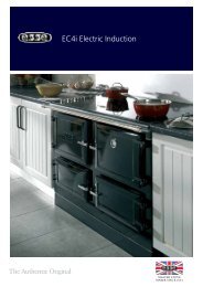
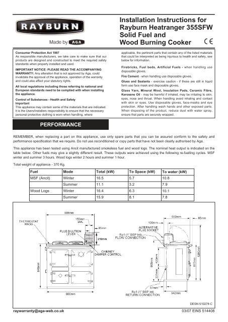
<strong>Installation</strong> <strong>Instructions</strong> <strong>for</strong><strong>Rayburn</strong> <strong>Heatranger</strong> <strong>355SFW</strong><strong>Solid</strong> <strong>Fuel</strong> andWood Burning CookerConsumer Protection Act 1987As responsible manufacturers, we take care to make sure that ourproducts are designed and constructed to meet the required safetystandards when properly installed and used.IMPORTANT NOTICE: PLEASE READ THE ACCOMPANYINGWARRANTY: Any alteration that is not approved by Aga, couldinvalidate the approval of the appliance, operation of the warrantyand could also affect your statutory rights.All local regulations including those referring to national andEuropean standards need to be complied with when installingthe appliance.Control of Substances - Health and SafetyImportantThis appliance may contain some of the materials that are indicated.It is the Users/Installers responsibility to ensure that the necessarypersonal protective clothing is worn when handling, whereapplicable, the pertinent parts that contain any of the listed materialsthat could be interpreted as being injurious to health and safety, seebelow <strong>for</strong> in<strong>for</strong>mation.Firebricks, <strong>Fuel</strong> beds, Artificial <strong>Fuel</strong>s - when handling usedisposable gloves.Fire Cement - when handling use disposable gloves.Glues and Sealants - exercise caution - if these are still in liquid<strong>for</strong>m use face mask and disposable gloves.Glass Yarn, Mineral Wool, Insulation Pads, Ceramic Fibre,Kerosene Oil - may be harmful if inhaled, may be irritating to skin,eyes, nose and throat. When handling avoid inhaling and contactwith skin or eyes. Use disposable gloves, face-masks and eyeprotection. After handling wash hands and other exposed parts.When disposing of the product, reduce dust with water spray,ensure that parts are securely wrapped.PERFORMANCEREMEMBER, when replacing a part on this appliance, use only spare parts that you can be assured con<strong>for</strong>m to the safety andper<strong>for</strong>mance specification that we require. Do not use reconditioned or copy parts that have not been clearly authorised by Aga.This appliance has been tested using Ancit manufactured smokeless fuel and wood logs. The nominal heat output is indicated on thetable below. Other fuels may give a slightly different result. These outputs were achieved using the following re-fuelling cycles. MSFwinter and summer 3 hours. Wood logs winter 2 hours and summer 1 hour.Total weight of appliance - 370 Kg.<strong>Fuel</strong>ModeTotal (kW)To Space (kW)To water (kW)MSF (Ancit)Winter16.55.710.8Summer11.13.27.9Wood LogsWinter16.46.310.1Summer15.98.17.8DESN 510278 Craywarranty@aga-web.co.uk03/07 EINS 514408
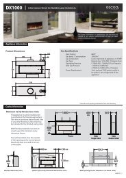
Fig.1There is no requirement <strong>for</strong> an electrical power supply althougha low limit thermostat is incorporated in the boiler and if usedmust be earthed.The <strong>Rayburn</strong> <strong>355SFW</strong> is intended to supply heating <strong>for</strong>:-(a) Cooking and domestic hot water.(b) Cooking, domestic hot water and central heating.Air <strong>for</strong> combustion within the firebox is obtained from twosources viz:-a) When the appliance is being used <strong>for</strong> cooking and domestichot water only, the rate of burning is determined by themanually operated spinwheel control on the ashpit door.b) When central heating is also required, close the spinwheelcontrol and operate the burning rate by means of the boilerthermostat.The cooker has both boiler and cooker flues which areopened/closed by internal dampers working in conjunction andoperated manually by the cooker/boiler damper at the front ofthe cooker.The setting should be relative to the services required, viz:- H<strong>for</strong> all services, C <strong>for</strong> cooking and domestic hot water only.COOKER POSITIONDESN 510279 BWhen the cooker is installed in a recess it must be‘freestanding’ and not built-in solid at the sides. Ensure that anycombustible material e.g. kitchen furniture is spaced away fromthe cooker to the recommended distances. See Fig. 1.TilingWhere the cooker is to stand in a recess or against a wall whichis to be tiled, in no circumstances should the tiles overlapthe cooker top plate.WARNINGTHE ASHPIT AND FIREBOX DOORS MUST BE LOCKEDCLOSED AT ALL TIMES DURING NORMAL USE, EXCEPTWHEN LIGHTING OR RE-FUELLING.PREPARATION OF SITEThe non-combustible hearth must be solid and level andtogether with the walls adjacent to the cooker and chimney,con<strong>for</strong>m to current Building Regulations.The cooker and chimney flue installation should be inaccordance with the relevant recommendations of the BritishCodes of Practice BS 8303, BS 6461 Part 1 and BS 7566 Parts1 to 4 respectively and the central heating system to BS 5449Part 1. The boiler installation section must also be inaccordance with the byelaws of the local Water Undertaking,Regulations <strong>for</strong> the Electrical Equipment of Buildings -published by the Institute of Electrical Engineers and anyrelevant requirements of the Local Authority.Ensure that any electrical wiring is correctly earthed.2
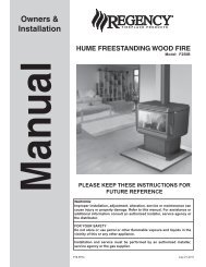
BUILDERS OPENINGFrom 200mm thick non-combustible or new recesses, anopening of 1,080mm wide minimum, by 343mm deep minimumand 1,680mm high minimum from floor is recommended.NOTE (SEE FIG. 1): PLEASE NOTE IT IS ADVISABLE TOCHECK THE SIZE/WIDTH OF YOUR APPLIANCE BEFOREFINALLY FIXING ANY KITCHEN UNITS SINCE ENAMELLEDCAST IRON CAN VARY IN SIZE.THE CHIMNEYThe minimum chimney draught requirement at nominal totalheat output is 12 Pa.The mean flue gas temperature directly downstream of the fluespigot at nominal heat output is 247ºC.This appliance is not suitable <strong>for</strong> installation in a shared fluesystem.The minimum clearance to combustible materials is 150mm.Checking existing chimneyThe internal and external condition of the chimney should bechecked be<strong>for</strong>e the appliance is installed and rectificationmade where necessary to prevent leakage or porosity. Thesoundness of the chimney which should have a minimum fluedimension of 175mm square or 185mm diameter can beconfirmed by smoke testing. Advice on the test method can beobtained from HETAS.When repairing or re-using chimneys its recommended that thebuilding control office be consulted be<strong>for</strong>e the commencementof work with particular attention to the chimney height and itstermination.The chimney must be swept be<strong>for</strong>e installation.Erecting New ChimneyThe flue through the chimney should be <strong>for</strong>med with pre-castmoisture and acid-resistant liners with a minimum internaldimension of 185mm square and all in accordance with thecurrent Building Regulations (England and Wales) and inScotland the Building Standards (Scotland) (Consolidation)Regulations and the Codes of Practice <strong>for</strong> chimneys and fluesBS. 6461 Part 1 and BS 7566 Parts 1 to 4.Ensure the chimney liners are free of projecting internalbuilding jointing composition be<strong>for</strong>e the appliance is installed.Factory made Insulated ChimneysIt is recommended the chimney be ceramic lined and complywith BS. 4543.The minimum diameter <strong>for</strong> a straight chimney is 175mm and ifoffsets are fitted the recommended minimum diameter is200mm.IN ALL TYPES OF CHIMNEYS THE MINIMUM HEIGHT FORCORRECT OPERATION OF THE COOKER IS 4.5m ANDSHOULD TERMINATE ABOVE THE ROOF IN ACCORDANCEWITH REGIONAL STATUTORY REQUIREMENTS.RECOMMENDED FLUE DRAUGHT - 12 Pa MINIMUM. THEAPPLIANCE SHOULD BE INSTALLED AND CONFORM TOTHE CURRENT CODES OF PRACTICE FOR INSTALLATIONOF DOMESTIC HEATING AND COOKING APPLIANCESBURNING SOLID FUEL - BS 8303.ALWAYS ADVISE THE USER TO CLEAN THE COOKERFLUES IN ACCORDANCE WITH THE OPERATINGINSTRUCTIONS AND TO HAVE THE CHIMNEY SWEPT ATFig. 2Fig. 3Fig. 4DESN 510281 BDESN 510282 BDESN 510283 B3
A MINIMUM OF 12 MONTHLY INTERVALS AFTER THECOOKER IS COMMISSIONED.WARNING: PROLONGED SOOT FORMATION MAY RESULTIN THE FLUEWAYS BECOMING BLOCKED AND COULDGIVE RISE TO THE RELEASE OF CARBON MONOXIDE, APOISONOUS GAS INTO THE ROOM.COOKER FLUE CONNECTIONThe position of available types of flue layouts are shown inFigs. 2, 3 and 4, the cooker flue chamber is adaptable toprovide either top or back flue outlets, by means of thereversible loose socket.(a)Rear Flue OutletThis must only be used where there is a brick flueimmediately behind the cooker. Provision must be made <strong>for</strong>a condensate collecting vessel and cleaning door. See Fig. 3.NOTE: EXTENDED REAR FLUE PIPE AND BENDS ARE NOTRECOMMENDED.(b)Top Flue OutletThe cooker should be connected to the main flue via a150mm minimum diameter cast iron pipe or appropriatelyinternally externally vitreous enamelled mild steel pipe andbe sealed to the cooker flue chamber with soft rope and firecement.Any bends in the flue pipe must be not less than 135º (45ºfrom horizontal) and be complete with a cleaning door.Fig. 5 Typical CentralHeating/Hot Water SystemDESN 510284’A’FLUE LAYOUTSIn Fig. 2. the cooker is installed in an existing recess. Theremust be a clearance of not less than 150mm between the top ofthe flue pipe and any overhanging brickwork.Any cavities or pockets above the register plate should as faras possible be filled and if necessary the flue pipe should beextended into the throat of the chimney and soot door provided<strong>for</strong> chimney sweeping.If a flue liner or insulated chimney is used, the size should notbe less than 185mm square or 225mm diameter, and 175mmdiameter respectively.In Fig. 3, the cooker is connected direct to a brick flue.Horizontal pipe runs between cooker and brick flue must notbe used.In Fig. 4, the cooker is connected to an existing brick flue with alength of flue pipe. Square bends and horizontal runs must notbe used. There must be a cleaning door at every bend.NOTE: WHATEVER METHOD OF INSTALLATION ISEMPLOYED, AIR MUST NOT BE ALLOWED TO ENTER THECHIMNEY EXCEPT THROUGH THE COOKER. ALL JOINTSMUST BE AIR-TIGHT.If the chimney is unlined, and there is any doubt about itscondition, it should be lined in accordance with current BuildingRegulations.PROVISION MUST ALWAYS BE MADE FOR SWEEPINGTHE CHIMNEY.IMPORTANT: CEMENT TYPE PIPES AND FITTINGS MUSTNOT BE USED WITHIN 2m. OF THE COOKER. CHIMNEYSOF PLAIN PIPE ARE NOT RECOMMENDED BUT CERTAINPROPRIETARY MAKES OF INSULATED CHIMNEY ARESUITABLE.Fig.6 Typical Wiring DiagramAIR SUPPLYDESN 510285Provision must be made <strong>for</strong> a permanent unobstructed air venthaving a minimum effective area of 55cm 2 (8.5 sq in)communicated directly to outside air or an adjacent room whichitself has a permanent air vent of at least this size direct tooutside air.If a flue draught stabiliser is fitted in the flue this appliancerequires a permanent open air vent of 100 cm 2 .Any air inlet grilles must be positioned so that they are notliable to blockage.It is not permissible to use an air extraction device in the sameroom as the appliance, unless additional ventilation is providedto prevent any adverse effect on the flue.Effect of Extractor FanAvoid if possible the installation of extractor fan in the sameroom as the cooker. Compensating extra air inlets must beintroduced equivalent to the capacity of the fan when fitted.4
CENTRAL HEATING ANDHOT WATER SYSTEMIt is recommended that a 190 litre (40 galls) indirect hot waterstorage cylinder of the double feed type e.g. (Manufactured byAlbion Cylinders, complying with BS. 1566 Part 1:DF Type 10)should be lagged and fixed vertically as near as possible to thecooker.The 28mm minimum diameter primary flow and return pipesmust not exceed 10m in length and pipes longer than 5m mustbe lagged.Ensure that the flow pipe has an open vent and risescontinuously from the boiler to the cylinder to ensure goodgravity circulation.In combined systems, the water draw-off pipes to the taps mustbe dead-leg connection from the vent/expansion pipe.There are only two boiler tappings on this cooker and a typicaldesign layout is shown in Fig. 5.An injector tee is provided which must be fitted to ensureadequate primary flow circulation when the water circulator isoperating, otherwise there may be a lack of domestic hot water.The heating flow and return pipes may be 22mm, the returnpipe being connected to the 28mm primary return by theinjector tee, and the tee outlet connected to the boiler returnpipe.All installations must be fitted with a drain tap at the lowestpoint of the system.BOILER - ControlIn order to maximise the life of your boiler body, an electricalthermal re-set low temperature boiler thermostat has been fittedwithin the appliance, behind the LH side removable cover,whose purpose is to isolate the electrical power from the watercirculator when the boiler thermostat falls below 60ºC (140ºF)and thus minimise harmful condensation on the boiler surfaces.The 3 core 0.75mm 2 cable lead from the appliance must beconnected to/from the water circulator as indicated on the‘Typical Wiring Diagram’ in Fig. 6.NOTE: IF THERE IS A POSSIBILITY OF BOILING TAKINGPLACE A REVERSE ACTING THERMOSTAT SHOULD BEFITTED TO THE DOMESTIC HOT WATER CYLINDER ORBOILER PRIMARY FLOW PIPES, AND ELECTRICALLYCONNECTED TO THE CENTRAL HEATING PUMP, THISWILL SWITCH THE PUMP ‘ON’ TO PREVENT BOILING. ATLEAST ONE RADIATOR (USUALLY THE BATHROOM)SHOULD NOT BE FITTED WITH A TRV (THERMOSTATICRADIATOR VALVE), TO ACT AS A HEAT LEAK, SHOULDTHE BOILER OVERHEAT AND THE PUMP START.HIGH UPDRAUGHTSTall chimneys may develop excessively high updraughts whichprevent the appliance operating correctly.It is recommended that a proprietary brand adjustable fluedraught stabiliser having an openable cross sectional area of182.5sq cm (6”ø pipe) be fitted above the flue pipe connection,either in the brickwork or into a right angle ‘T’; fitting in the fluepipe position that will not inconvenience appliance operation ormaintenance.5
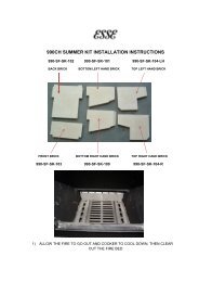
GENERAL - Firebrick Positionsand ReplacementThe <strong>Rayburn</strong> <strong>355SFW</strong> is delivered complete including a set ofboiler removable firebricks where positional location determinesthe amount of hot water supplied in winter and summerseasons.The oven side and firebox front firebricks are permanently fixedwith fire cement, whilst the two boiler face side bricks and boilerback brick are located <strong>for</strong> the summer season thereby providingdomestic hot water only. For winter use or central heatingfacilities, the boiler face rear brick is removed and the boilerface side bricks are transferred to locate on/over the oven sidefirebricks. See diagram 7 & 7A.The firebricks fitted to the <strong>Rayburn</strong> Cookers are of first qualitymanufacture, and providing the cooker has been installed andused correctly will have a reasonable life. These are, however,expendable items and in time will require renewal. The renewalof firebricks is not a major operation and can be carried out bythe average handyman. Replacement bricks either in sets orsingly can be obtained from your <strong>Rayburn</strong> Distributor. Quotethe serial number which will be found on the appliance dataplate.Fig. 7A DESN 510287SUMMER USE (DOMESTIC HOT WATER ONLY) SIDEFIREBRICKS ‘A’ MOUNTED IN LEFT HAND SIDE OFFIREBOX & REAR FIREBRICK ‘B’ IN POSITION.Fig. 8DESN 510291Note (Fig. 8) - Position of grate baffle <strong>for</strong> woodburning onlyFig. 7 DESN 510286WINTER USE (DOMESTIC HOT WATER & CENTRALHEATING) SIDE FIREBRICKS ‘A’ MOUNTED IN RIGHTHAND SIDE OF FIREBOX OVER PERMANENTLY FIXEDOVEN SIDE FIREBRICKS & REAR FIREBRICK ‘B’REMOVED.6
INSTALLATIONPlace the cooker in the intended position and out lift the surfaceground hotplate, checking that the joint between the undersideof the hob and the top of the cooker is intact.Any joints which have opened should be made good with firecement provided.If the appliance is installed near combustible material then aswell as adhering to minimum clearances in Fig. 1 additionalnon-combustible insulation must be fitted to the wall to protectthe area around the flue and fluebox. The insulation must reacha minimum distance of 150mm either side of the flue/flue boxand follow the line of the flue. The minimum specification <strong>for</strong>this material is Superwool 607 LTI with a density of 320kg/m 3 ,a thickness of 10mm and a self finish. There must be aminimum 16mm air gap between the insulation board and anadjacent combustible wall surface. A higher specificationmaterial may be used but the air gap must be maintained.Check that the boiler/cooker flueway dampers operate correctlyby turning the knob on the front plate adjacent to the top lefthand corner of the roasting oven door.NOTE: IT IS NOT VISUALLY POSSIBLE TO SEE THEBOILER DAMPER AND THIS SHOULD BE CHECKED BYFEELING THROUGH THE HOTPLATE APERTURE TO THEBACK OF THE COOKER. THE COOKER DAMPER SPINDLEOPERATES THE BOILER DAMPER WHICH CAN BE FELTBY INSERTING HAND INTO FLUEWAY.Replace the hotplate making sure that it is seating evenly onthe soft rope and that it is approximately 1.5mm proud of theenamelled top plate, with an equal space all round.1. Connect pipework to boiler flow and return tappings.2. Fit the flue chamber which should have a rope seal alreadyinstalled. The flue chamber is screwed to the cooker makinga good seal as any air leak at this point will impede theworking of the cooker.3. Open the firebox and ashpit doors and check that thereciprocating bottomgrate bars are in position. Operate theriddling lever to ensure bottomgrate operation.4. Turn the boiler thermostat knob at the rear left hand cornerof the top plate from No.1 (low) to No.8 (high).NOTE: THE HIGHER THE NUMBER, THE HIGHER THEWATER TEMPERATURE.The handrail brackets are held on the front ends of the cookertop-plate casting. Remove the travel nuts and replace with thehandrail brackets ensuring the fibre protecting washers are inposition. Insert the handrails with fitted endcaps into thebrackets, positioning them correctly, and tighten the locatingbolts (Fig. 9).TESTING AND COMMISSIONINGAfter completing the installation, the Heating Contractor shoulddemonstrate to the user, the operation of the appliance and theroutine cleaning method.Check that the system is full of water and free from air locks.When lighting pull the flue chamber damper open to maximum,add paper and sticks with a small quantity of fuel throughfuelling aperture onto bottomgrate and close the firebox door.Open ashpit door, ignite fuel and close ashpit door when fuel iswell alight with boiler thermostat knob or spinwheel on ashpitdoor at required setting.Allow the cooker to heat up gradually at first time lighting.NOTE: SMOKE/SMELL EMITTED DURING INITIAL USAGESome parts of the cooker have been coated with a lightcovering of protective oil. During initial operation of the cooker,this may cause smoke/smell to be emitted and is normal andnot a fault with the appliance, it is there<strong>for</strong>e advisable to opendoors and or windows to allow <strong>for</strong> ventilation. Lift the lids toprevent staining the linings.Fig. 9DESN 510454 A7
For further advice or in<strong>for</strong>mation contact yourlocal distributor/stockistWith Aga’s policy of continuous productimprovement, the Company reserves the right tochange specifications and make modifications tothe appliance described at any time.Manufactured byAgaStation RoadKetley Tel<strong>for</strong>dShropshire TF1 5AQEnglandwww.aga-web.co.ukwww.agacookshop.co.ukwww.agalinks.com8