Home Controller HC-200 Installation Guide - Control4
Home Controller HC-200 Installation Guide - Control4
Home Controller HC-200 Installation Guide - Control4
- No tags were found...

Create successful ePaper yourself
Turn your PDF publications into a flip-book with our unique Google optimized e-Paper software.
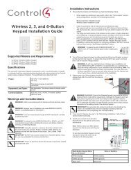
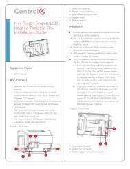
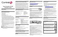
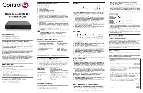
<strong>Home</strong> <strong>Controller</strong> <strong>HC</strong>-<strong>200</strong><strong>Installation</strong> <strong>Guide</strong>Supported ModelsC4-<strong>HC</strong><strong>200</strong>-E-B <strong>Home</strong> <strong>Controller</strong> <strong>HC</strong>-<strong>200</strong>C4-<strong>HC</strong><strong>200</strong>-E-B-NR <strong>Home</strong> <strong>Controller</strong> <strong>HC</strong>-<strong>200</strong>Introduction to <strong>Home</strong> <strong>Controller</strong> <strong>HC</strong>-<strong>200</strong>The <strong>Control4</strong>® <strong>Home</strong> <strong>Controller</strong> <strong>HC</strong>-<strong>200</strong> provides options for controllinglights, home theaters, distributed audio systems, distributed video systems,and other devices controlled using various protocols, such as Infra Red (IR)and Serial (see IR Out description).It provides extensive media management services for audio and videosources, such as CDs and DVDs stored in connected devices. It also allowsyou to use an external storage device with USB support for media storage. Italso includes multi-zone audio capabilities, sending music to roomsthroughout the home.When the <strong>Controller</strong> and other system components are installed andconfigured, your users can control the system using a number of interfaces,such as the two included with this <strong>Controller</strong>: On-screen Navigator and aSystem Remote Control (sold separately with C4-<strong>HC</strong><strong>200</strong>-E-B-NR).For more information, refer to theEnd-user Documentation CD included with this device.What’s in the BoxThe following are included in your <strong>Home</strong> <strong>Controller</strong> box:• <strong>Home</strong> <strong>Controller</strong> <strong>HC</strong>-<strong>200</strong>• System Remote Control SR-150 and 4 AAA batteries (the SR-150 is soldseparately with C4-<strong>HC</strong><strong>200</strong>-E-B-NR)• AC to DC power adapter with power cord• IR emitters (4)• Universal Mounting Plate• Screws (4)• <strong>Control4</strong> End-user Documentation CD• <strong>Home</strong> <strong>Controller</strong> <strong>HC</strong>-<strong>200</strong> <strong>Installation</strong> <strong>Guide</strong> (this document)Accessories Available for Purchase• USB WiFi Adapter (C4-NWA-11G-USB)• Rack-Mount Kit (C4-1URMK1-B)• Serial Cable Kit (C4-CBL3.5MM-DB9)Important Safety Instructions1. Read these instructions.2. Keep these instructions.3. Heed all warnings.4. Follow all instructions.5. Do not use this apparatus near water.6. Clean only with dry cloth.7. Install in accordance with the manufacturer’s instructions.8. Do not install near any heat sources such as radiators, heat registers,stoves, or other apparatus (including amplifiers) that produce heat.9. Protect the power cord from being walked on or pinched particularly atplugs, convenience receptacles, and the point where they exit from theapparatus.10. Only use attachments/accessories specified by the manufacturer.11. Unplug this apparatus during lighting storms or when unused for longperiods of time.12. Refer all servicing to qualified service personnel. Servicing is requiredwhen the apparatus has been damaged in any way, such as power-supplycord or plug is damaged, liquid has been spilled or objects have falleninto the apparatus, the apparatus has been exposed to rain or moisture,does not operate normally, or has been dropped.WARNING! To reduce the risk of electrical shock, do not expose thisapparatus to rain or moisture.AVERTISSEMENT! Pour réduire le risque de choc électrique,n'exposez pas cet appareil à la pluie ou à l'humidité.WARNUNG! Um das Risiko des elektrischen Schlages zu verringern,setzen Sie diesen Apparat nicht Regen oder Feuchtigkeit aus.<strong>Control4</strong> ® Supported Devices<strong>Control4</strong> devices that communicate with this <strong>Controller</strong> include:Touch Screens—All types and sizes(such as handheld, table top, and wallmounted,or 10”, 7”, and mini)LCD KeypadsWireless 2, 3, & 6 Button KeypadsWireless ThermostatsSpeaker Points ®Audio Matrix SwitchFor a more information, refer to “Products” at http://www.control4.com.Requirements and Specifications• If you are using the Ethernet networking option, the Ethernet networkshould be in place prior to starting the installation.• If you are using the WiFi networking option, you must install and set upthe WiFi adapter (sold separately) in order to complete the installation.• Software required for configuration is Composer Pro or an alternative(less flexible) <strong>Control4</strong> ® setup program, such as Easy Setup Program.The <strong>Home</strong> <strong>Controller</strong> <strong>HC</strong>-<strong>200</strong> specifications include:Model Number • C4-<strong>HC</strong><strong>200</strong>-E-BNetwork Support • Ethernet—required (included)• WiFi--optional, requires a WiFi adapter (soldseparately)Media Recognition • AMG online CD/DVD recognition and mediainformation serviceAudio Playback Formats • MP3: 32kbps to 320kbps, CBR and VBRDisplay • LED indicatorsPower Requirements • 100-240 VAC, 60/50 Hz, 0.50 A MAXDimensions • H x W x D: 1.44” (36.5 mm) x 8.55 (217 mm) x5” (127 mm) (with connectors and mountingplate)Weight • 1.8 lbs/0.82 kgAdditional ResourcesMulti Channel Amplifiers4-Zone AmplifiersMulti Tuners (V1 or V2)Wireless DimmersWireless SwitchesWireless Outlet DimmersWireless Outlet SwitchesThe following resources are available to provide you with additional support.• Your <strong>Control4</strong> Reseller• <strong>Control4</strong> Web Site: http://www.control4.com• Composer online helpFront View1. IR Window / IR Blaster—For capturing third-party IR codes from handhelddevices (such as remote controls) or blasting IR codes. The WiFiLED blinks red when capturing IR codes.2. WiFi LED—This LED blinks orange and then blue during the boot process.When the operating system is running, the WiFi driver changes theLED color depending on the signal strength of its connection to its associatedaccess point. Colors and signal strength are as follows: orange =Fair to Good, blue = Excellent, and no light = No connection.3. Data LED—This blue LED indicates streaming audio is received.4. Link LED/Identification button—Blue LED light indicates that the <strong>Home</strong><strong>Controller</strong> has been identified in a <strong>Control4</strong> Composer project. Press thisbutton to identify this device in Composer.5. Power LED—Blue LED light indicates AC power is present. It turns onimmediately after the power is applied to the device.Back View1. Audio In (1)—3.5 mm jacks for stereo channel input (line level) for onestereo analog source.2. Audio Out (1 left-right pair)—RCA jacks for stereo channel line output(line level) for amplifiers or audio switches.3. Video Out—Composite RCA and Component RCA jacks.4. Serial Port (up to 2) or IR Out (up to 4)—3.5 mm jacks for up to 4 IRemitters or for a combination of IR emitters and serial devices (up to 2).Jacks 1 and 2 can be configured independently for serial devices, suchas receivers or disk changers (requires serial cable, sold separately.)5. USB (1 port)—For external storage device with USB support (such asFAT32 formatted devices) or WiFi adapter (C4-NWA-11G-USB).6. Ethernet—RJ-45 jack for a 10/100 Base T Ethernet connection.7. Power plug port—DC power supply port.Install the <strong>HC</strong>-<strong>200</strong>1 2 3 4 51 2 3 4 5 6 7To install this controller:1. Ensure that your home network is in place before starting your systemsetup: The <strong>Home</strong> <strong>Controller</strong> <strong>HC</strong>-<strong>200</strong> requires a network connection(wired or WiFi) to use all features as designed. When connected, the<strong>Home</strong> <strong>Controller</strong> can access Web-based media databases and <strong>Control4</strong>®system updates.2. Connect the <strong>HC</strong>-<strong>200</strong> controller to the network: To connect using anEthernet connection, plug the data cable from the home network connectioninto the <strong>Home</strong> <strong>Controller</strong> RJ-45 port (labeled “Ethernet”) and the networkport on the wall or at the network switch.NOTE: To connect using the optional USB WiFi adapter (C4-NWA-11G-USB), refer to the installation instructions shipped with the adapter.Only use the power supply included in this box.3. Power up the controller: Plug the DC power supply into the <strong>Home</strong> <strong>Controller</strong>power plug port and an electrical outlet.4. Connect system devices: As described in the “Connect Devices” sectionthat follows.Mount the <strong>HC</strong>-<strong>200</strong> on a Wall (Optional)1. Mount the <strong>HC</strong>-<strong>200</strong> horizontally using 1 standard single-gang wallbox: The wall mounting plate has 4 horizontal sets of slots. Install a single-gangwall box. Leave the screws protruding .08” from the wall.Mount the <strong>HC</strong>-<strong>200</strong> horizontally or vertically using 1 standard doublegangbox: Install a standard double-gang box. Leave the screwsprotruding .08” from the wall.Mount the <strong>HC</strong>-<strong>200</strong> horizontally or vertically using 4 screws (not provided)placed directly into a wall stud or studs: Using the mountingplate as a template, screw 4 screws into a stud to align with the 4 centerslots for vertical positioning or into 2 studs to align with the 4 corner slotsfor horizontal positioning. Leave the screws protruding .08” from the wall.NOTE: To quickly check the fit of the screws, place the wall mounting plateover the screws before attaching it to the bottom of the <strong>Controller</strong>.slots for mountingcontroller horizontallyholes forattaching plateto controllerslots formountingcontrollervertically2. Use the 4 screws (provided) to attach the mounting plate to the bottom ofthe <strong>Controller</strong>. Ensure that the narrow end of the slots will be on top whenthe device is installed.3. Arrange the wires to fit in the wire channels on the mounting plate.4. Line the slots on the mounting plate up with the screws.5. Press the device onto the screws and slide down until the screws are inthe narrow end of the slots.Configure the <strong>HC</strong>-<strong>200</strong>Configure Video Output ModeThe default video output mode is NTSC over composite. In this mode, somebleed-through of the NTSC signal on the component video outputconnections occurs. However, the video image will not appear correctly inthis mode. The <strong>HC</strong>-<strong>200</strong> can be configured to output over component usingNTSC (standard definition) or 720p (high definition). To configure the videomode to use the component video outputs, make the appropriate bindings forthe desired video output mode in Composer.Connect DevicesNOTE: You can use the Composer software to step through the connectionprocess before or after the physical connections are complete.Connect all applicable devices to the <strong>Home</strong> <strong>Controller</strong> <strong>HC</strong>-<strong>200</strong> using one ofthe connection options described in the following table.Table 1. Connection OptionsAudio In (1)—3.5 mm jacks for stereo channel input (line level) for 1 stereoanalog source.Audio Out (1 left-right pair)—RCA jacks for stereo channel lineoutput (line level) for amplifiers or audio switches.Video Out Options—Composite or Componentport for displaying navigation menus on a monitoror TV. The Component jack is used for displayingstandard or high-definition video.To display standarddefinition video, use the Composite port.Serial Port (up to 2) or IR Out (up to 4)—3.5 mmjacks for up to 4 IR emitters or for a combination ofIR emitters and serial devices (up to 2). Jacks 1 and2 can be configured independently for serial devices, such as receivers or diskchangers. See “Set Up IR Emitters or IR Blaster” for more information.USB (1 port)—For external storage device with USB support (such as FAT32formatted devices). See “Using External Storage Devices” for more informationor for connecting the optional WiFi adapter C4-NWA-11G-USB.Ethernet—RJ-45 for a 10/100 BaseT Ethernet connectionPower plug port—For use with the DC power supply(provided)
Connect the IR Ports/Serial Ports (Optional)The <strong>HC</strong>-<strong>200</strong> provides 4 IR ports; Jacks 1 and 2 can be reconfiguredindependently for serial communication. Any jack not used for serial can beused for IR. Connect a device to the <strong>HC</strong>-<strong>200</strong>, like a receiver or disk changerusing the special serial cable (optional). Serial ports support many differentbaud rates. The table below shows the serial communication values.HardwareFlow ControlTo configure a port for serial or for IR, make the appropriate connections inyour project using Composer.Set Up IR Emitters or IR BlasterYour system may contain third-party products that are controlled with IRcommands (usually through remote controls). To provide a way for the <strong>Home</strong><strong>Controller</strong> to control a device that only recognizes IR commands, completeone of the following setups: IR Emitters or IR Blaster.IR Emitters1. Plug the 3.5 mm connector end of one of the 4 IR stick-on emitters providedinto an IR Out port on the <strong>HC</strong>-<strong>200</strong>.2. Place the stick-on emitter end over the IR receiver on the media player,TV, or other target device to drive IR signals from the <strong>HC</strong>-<strong>200</strong> to thetarget.IR BlasterIn addition to IR emitters, the <strong>HC</strong>-<strong>200</strong> is also equipped with an IR blaster,which is located just left of the front LEDs. To use the blaster instead of an IRemitter:1. In Composer, connect the Front IR Out of the <strong>Home</strong> <strong>Controller</strong> to the IR Inof the device you want to control.2. Test and verify that the <strong>HC</strong>-<strong>200</strong> is positioned in such a way that theblaster can reach the device you want to control.TroubleshootingTo reset the <strong>HC</strong>-<strong>200</strong>, press and hold the Identification button until the WiFiLED blinks orange, signaling the start of the boot process.To reset to network defaults (wired connection), power cycle the <strong>HC</strong>-<strong>200</strong> andhold the Identification button until the Data, Link, and Power LEDs are solidblue, and then immediately release.If during the boot sequence, the WiFi LED stays orange, press and hold theIdentification button until the LED blinks blue, then release.Regulatory ComplianceOdd Parity Even Parity No Parity OtherSerial Port 1 X X XSerial Port 2 X X XSerial Port 3 X 8 bits/char; 1stop bitSerial Port 4 X 8 bits/char; 1stop bitIMPORTANT! Any changes or modifications not expressly approvedby the party responsible for compliance could void the user’sauthority to operate this equipment.IMPORTANT! Tous les changements ou modifications pasexpressément approuvés par la partie responsable de la conformitéont pu vider l'autorité de l'utilisateur pour actionner cet équipement.WICHTIG!Alle mögliche Änderungen oder Änderungen nichtausdrücklich genehmigt von der Partei, die für Befolgungverantwortlich ist, konnten die Berechtigung des Benutzersaufheben, um diese Ausrüstung zu betreiben.This product has been designed and tested to the following U.S., Canadian,European, Australian, and New Zealand standards.North AmericaFederal Communications Commission (FCC)FCC ID: R33C4<strong>HC</strong><strong>200</strong>1—This device complies with Part 15 of the FCCRules. Operation is subject to the following two conditions: (1) This devicemay not cause harmful interference, and (2) this device must accept anyinterference received, including interference that may cause undesiredoperation.This equipment has been tested and found to comply with the limits for aClass B digital device, pursuant to Part 15 of the FCC Rules. These limits aredesigned to provide reasonable protection against harmful interference in aresidential installation. This equipment generates, uses, and can radiateradio frequency energy and, if not installed and used in accordance with theinstructions, may cause harmful interference to radio communications.However, there is no guarantee that interference will not occur in a particularinstallation. If this equipment does cause harmful interference to radio ortelevision reception, which can be determined by turning the equipment offand on, the user is encouraged to try to correct the interference by one of thefollowing measures:• Reorient or relocate the receiving antenna.• Increase the separation between the equipment and receiver.• Connect the equipment into an outlet on a circuit different from that towhich the receiver is connected.• Consult the dealer or an experienced radio/TV technician for help.Industry CanadaThis Class B digital apparatus complies with Canada ICES-003.Cet appareil numérique de la classe B est conforme à la norme NMB-003 duCanada.CAN/CSA-C22.2 No. 60065-03 1st ed., <strong>200</strong>6-04 +A1: <strong>200</strong>6 (Audio, video,and similar electronic apparatus)Operation is subject to the following two conditions: (1) this device may notcause interference and (2) this device must accept any interference,including interference that may cause undesired operation of the device.L'opération est sujette aux deux conditions suivantes : (1) ce dispositif peutne pas causer l'interférence et (2) ce dispositif doit accepter n'importe quelleinterférence, y compris l'interférence qui peut causer le fonctionnement peudésiré du dispositif.Canadian ID IC:7848A-C4<strong>HC</strong><strong>200</strong>EAustralian / New Zealand• AS/NZS CISPR 22: <strong>200</strong>2—Information Technology Equipment—Radiodisturbance characteristics.RecyclingFor recycling information, please go to www.control4.com/recycling.WarrantyLimited 2-year Warranty. Refer to http://www.control4.com/warranty.About This Document©<strong>200</strong>9 <strong>Control4</strong>. All rights reserved. <strong>Control4</strong>, the <strong>Control4</strong> logo andEveryday Easy are registered trademarks or trademarks of <strong>Control4</strong>Corporation in the United States and/or other countries. All other names orbrands may be claimed as property by their respective owners. Pricing andspecifications subject to change without notice. Part Number: <strong>200</strong>-00085,10/20/<strong>200</strong>9, Rev E