Wireless Thermostat Installation Guide and the Control4
Wireless Thermostat Installation Guide and the Control4
Wireless Thermostat Installation Guide and the Control4

Create successful ePaper yourself
Turn your PDF publications into a flip-book with our unique Google optimized e-Paper software.
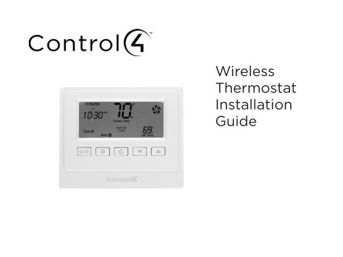
<strong>Wireless</strong><strong>Thermostat</strong><strong>Installation</strong><strong>Guide</strong>
DisclaimerTrademarks<strong>Control4</strong>® makes no representations or warranties with respect to any <strong>Control4</strong> hardware, software, or<strong>the</strong> contents or use of this publication, <strong>and</strong> specifically disclaims any express or implied warranties ofmerchantability or fitness for any particular purpose. <strong>Control4</strong> reserves <strong>the</strong> right to make changes to any<strong>and</strong> all parts of <strong>Control4</strong> hardware, software, <strong>and</strong> this publication at any time, without any obligation tonotify any person or entity of such changes.©2011 <strong>Control4</strong>. All rights reserved. All rights reserved. <strong>Control4</strong>, <strong>the</strong> <strong>Control4</strong> logo, <strong>the</strong> <strong>Control4</strong> iQ logo<strong>and</strong> <strong>the</strong> <strong>Control4</strong> certified logo are registered trademarks or trademarks of <strong>Control4</strong> Corporation in <strong>the</strong>United States <strong>and</strong>/or o<strong>the</strong>r countries. All o<strong>the</strong>r names <strong>and</strong> br<strong>and</strong>s may be claimed as <strong>the</strong> property of<strong>the</strong>ir respective owners. Pricing <strong>and</strong> specifications are subject to change without notice.<strong>Control4</strong> Corporation11734 S. Election Road, Suite 200Salt Lake City, UT 84020 USAhttp://www.control4.com<strong>Wireless</strong> <strong>Thermostat</strong> <strong>Installation</strong> <strong>Guide</strong>Part Number: 21-0170 Rev D, 9/20/2011Model Number: CCZ-T1-WWarrantyFor complete warranty information, including details on consumer legal rights as well as warranty exclusions,visit www.control4.com/warranty, or refer to <strong>the</strong> <strong>Control4</strong> <strong>Wireless</strong> <strong>Thermostat</strong> User <strong>Guide</strong> on <strong>the</strong><strong>Control4</strong> website, Resources > Documentation page at http://www.control4.com/residential/products/resources/.ii
Table of ContentsSupported Model ........................................................................................................... 1Important Safety Instructions ................................................................................... 1General Description ...................................................................................................... 1Box Contents ................................................................................................................... 2Requirements .................................................................................................................. 2Specifications ................................................................................................................. 3Pre-<strong>Installation</strong> Considerations ................................................................................ 4<strong>Installation</strong> Instructions................................................................................................ 7Composer Programming Instructions ...................................................................... 11<strong>Thermostat</strong> Relays ........................................................................................................ 16Troubleshooting ............................................................................................................ 22Installing a Bypass Resistor to Enable Power Stealingon a <strong>Wireless</strong> <strong>Thermostat</strong>............................................................................................................................................... 23Sample Wiring Configurations ................................................................................. 28Wiring Connections ...................................................................................................... 29Regulatory Compliance .............................................................................................. 36Warranty .......................................................................................................................... 36iii
Box Contents• <strong>Wireless</strong> <strong>Thermostat</strong>• CR123A (3V) battery• 3 screws (#6 x 1-inch sheet metal screws)• 3 plastic wall anchors (#4-6 x 7/8”)• Warranty card• U-shaped terminal jumper wire• Power-stealing bypass resistor (270 Ohm)• <strong>Control4</strong> <strong>Wireless</strong> <strong>Thermostat</strong> <strong>Installation</strong> <strong>Guide</strong> (this document)Requirements• Pencil (#2 or darker)• Drill with 3/16” drill bit• Small level (optional)• Small flat-blade screwdriver• Phillips screwdriver• Tape for labeling wires2
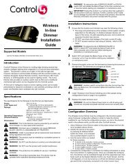
SpecificationsFront <strong>and</strong> Rear ViewFigure 1. FaceplateFigure 2. Rear PlateRecommended Wiring: 22 AWG (36 ft. max.)18 AWG (100 ft. max.)Power Source:24VAC <strong>and</strong> 3 volt batteryPower Usage:1/10W at 24VAC, 50/60 HzSet Point Temperature Range: 40˚ F to 90˚ F (5˚ C to 32˚ C)Operating Temperature: 39˚ F to 131˚ F (4˚ C to 55˚ C)Storage Temperature: 14˚ F to 185˚ F (-10˚ C to 85˚ C)Operating Relative Humidity: 0 to 95% (non-condensing)Dimensions (H x W x D): 4.5” x 3.7” x 1.2”Communications:ZigBee (IEEE 802.15.4) 2.4 GHz, 15-channel, spread spectrum radio3
IMPORTANT! The <strong>Wireless</strong> <strong>Thermostat</strong> has ‘power stealing’ enabled by default,however, it is recommended to power <strong>the</strong> <strong>Thermostat</strong> with a common wire. If powerstealing is required, verify that your HVAC system supports power stealing prior toinstallation in this mode.Changing this setting is described in Step 14, “<strong>Installation</strong> Instructions.” For moreinformation about power stealing, see “Installing a Bypass Resister to Enable PowerStealing on a <strong>Wireless</strong> <strong>Thermostat</strong>” later in this document.NOTE: The <strong>Wireless</strong> <strong>Thermostat</strong> requires power from <strong>the</strong> HVAC system to maintainregular communication with <strong>the</strong> Controller.Pre-<strong>Installation</strong> ConsiderationsUsing a Common Wire vs. Power StealingThe <strong>Wireless</strong> <strong>Thermostat</strong> can be configured to operate in a ‘power stealing’ condition when<strong>the</strong>re is no availability of a dedicated common wire. However, <strong>Control4</strong> recommends using adedicated common wire whenever possible. With some HVAC systems, power stealing can resultin system contention between <strong>the</strong> Cool <strong>and</strong> Heat Modes, <strong>and</strong> will render <strong>the</strong> HVAC systeminoperable. To aid in resolving this issue, a 270 Ohm 3 Watt Axial resistor is included with <strong>the</strong>packaging of each <strong>Wireless</strong> <strong>Thermostat</strong>. This resistor is intended to be installed between <strong>the</strong>W1 <strong>and</strong> <strong>the</strong> Common terminals inside <strong>the</strong> HVAC system. The resistor, when properly installed,will lower <strong>the</strong> risk of causing contention when <strong>the</strong> <strong>Thermostat</strong> is actively working in <strong>the</strong> Coolmode. Many HVAC systems will not tolerate a power-stealing <strong>Thermostat</strong> even with <strong>the</strong> 270ohm resistor installed properly. In this case, a dedicated common wire is a requirement forproper functionality.4NOTE: The battery is used for backup purposes only.
• New construction, <strong>Control4</strong> recommmends <strong>the</strong>se options:• Install a common wire.• Use a Remote Temperature Sensor in <strong>the</strong> wall where <strong>the</strong> <strong>Thermostat</strong> is located. Run a wire to<strong>the</strong> furnace, <strong>and</strong> <strong>the</strong>n install <strong>the</strong> <strong>Thermostat</strong> next to <strong>the</strong> furnace.• Retrofits, <strong>the</strong> best solution is to install <strong>the</strong> <strong>Thermostat</strong> using an existing common wire. If <strong>the</strong> boxdoes not have a common wire, you can:• Run a wire from <strong>the</strong> furnace to <strong>the</strong> <strong>Thermostat</strong> location.• Use Power Stealing (see Step 14 in “<strong>Installation</strong> Instructions”).• Install a Remote Temperature Sensor in <strong>the</strong> wall where <strong>the</strong> <strong>Thermostat</strong> is located. Run a wire to<strong>the</strong> furnace, <strong>and</strong> install <strong>the</strong> <strong>Thermostat</strong> next to <strong>the</strong> furnace. See “Remote TemperatureSensor.”• Use a separate 24VAC transformer to power <strong>the</strong> <strong>Thermostat</strong>.Supported System TypesThis table lists <strong>the</strong> items that <strong>the</strong> <strong>Thermostat</strong> replaces.DescriptionHeat pump (no aux. or emergency heat)Heat pump (with aux. or emergency heat)St<strong>and</strong>ard heating <strong>and</strong> cooling systemTwo-stage heat <strong>and</strong> two-stage cooledSt<strong>and</strong>ard heat-only systemsMillivolt heat-only systems - floor or wall furnacesSt<strong>and</strong>ard central air conditioningGas or oil heatElectric furnaceHydronic (hot water) - zone heat - 2 wiresHydronic (hot water) - zone heat - 3 wiresCCZ-T1-WYesYesYesYesYesYesYesYesYesYesNo5
Zoned Systems<strong>Control4</strong> supports zoned HVAC systems using a zoning panel. If used, however, a commonwire needs to be installed at <strong>the</strong> <strong>Thermostat</strong>. Power stealing is not an option in this case.Remote Temperature SensorA Remote Temperature Sensor allows <strong>the</strong> <strong>Thermostat</strong> to get its temperature readings from anarea where <strong>the</strong> <strong>Thermostat</strong> is not physically located. Typically, <strong>the</strong> <strong>Thermostat</strong> will be locatednear <strong>the</strong> HVAC equipment with only <strong>the</strong> Remote Temperature Sensor on <strong>the</strong> wall in <strong>the</strong> livingarea. This creates a much cleaner install. In this case, <strong>the</strong> <strong>Thermostat</strong> settings would be controlledusing any of <strong>the</strong> <strong>Control4</strong> user interfaces.A Remote Temperature Sensor is also a good solution in a retrofit when a common wire isnot available <strong>and</strong> power stealing is not an option. The <strong>Thermostat</strong> can be mounted in <strong>the</strong> mechanicalroom <strong>and</strong> wired directly to <strong>the</strong> HVAC equipment. The previously installed <strong>Thermostat</strong>wiring can <strong>the</strong>n be used to connect <strong>the</strong> <strong>Thermostat</strong> to <strong>the</strong> Remote Temperature Sensor.6
<strong>Installation</strong> Instructions1234Place <strong>the</strong> <strong>Wireless</strong> <strong>Thermostat</strong> in a proper location to ensure its efficiency <strong>and</strong> to avoidunnecessary cycling of <strong>the</strong> furnace or air conditioner.a. Place <strong>the</strong> <strong>Thermostat</strong> (or remote temperature sensor) away from direct sunlight,drafts, exterior doorways, skylights, windows, <strong>and</strong> exterior walls.b. Make sure <strong>the</strong> <strong>Thermostat</strong> gets strong ZigBee wireless reception: (1) Ensure that<strong>the</strong> <strong>Thermostat</strong> is within 150 feet of ano<strong>the</strong>r Zigbee device. (2) Avoid havingelectrical equipment that may cause interference with <strong>the</strong> Zigbee signal (suchas cordless telephones that operate on <strong>the</strong> 2.4 GHz frequency).Locate <strong>and</strong> turn OFF <strong>the</strong> power supply for <strong>the</strong> HVAC system.If installing a <strong>Thermostat</strong> in a new location, refer to “Sample Wiring Configurations” later inthis document for details on wiring <strong>the</strong> <strong>Thermostat</strong>, <strong>and</strong> <strong>the</strong>n go to Step 5.If replacing an existing <strong>the</strong>rmostat:a. Check <strong>the</strong> number <strong>and</strong> type of wires attached to <strong>the</strong> old <strong>the</strong>rmostat.b. When you’re sure <strong>the</strong> power is shut off, remove <strong>the</strong> old <strong>the</strong>rmostat from <strong>the</strong>wall, but do not disconnect any wires yet.c. If <strong>the</strong> old <strong>the</strong>rmostat has a letter identifying each wire, use a piece of tape tolabel each wire that corresponds to <strong>the</strong> letter on <strong>the</strong> old <strong>the</strong>rmostat, <strong>and</strong> ensure<strong>the</strong>y don’t fall back into <strong>the</strong> wall.d. Disconnect <strong>the</strong> old <strong>the</strong>rmostat.CAUTION! Discard <strong>the</strong> old <strong>the</strong>rmostat properly or recycle it. Mercury is ahazardous waste. You MUST dispose of it properly.7
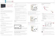
56789Remove <strong>the</strong> <strong>Control4</strong> <strong>Wireless</strong> <strong>Thermostat</strong> from <strong>the</strong> packaging, <strong>and</strong> detach <strong>the</strong> rear platefrom <strong>the</strong> <strong>Thermostat</strong>. (Press <strong>the</strong> release clip at <strong>the</strong> bottom of <strong>the</strong> <strong>Thermostat</strong> to release it,<strong>and</strong> <strong>the</strong>n swing <strong>the</strong> bottom of <strong>the</strong> <strong>Thermostat</strong> up.)Thread <strong>the</strong> wires from <strong>the</strong> wall through <strong>the</strong> back of <strong>the</strong> large rectangularopening in <strong>the</strong> new rear plate (see Figure 3), <strong>and</strong> <strong>the</strong>n position <strong>the</strong>new rear plate against <strong>the</strong> wall to make sure it sits flush.Use a small level or visually check that <strong>the</strong> rear plate is level; mark <strong>the</strong>locations of <strong>the</strong> three (3) screw holes on <strong>the</strong> wall (see Figure 4).Remove <strong>the</strong> rear plate from <strong>the</strong> wall <strong>and</strong> drill 3/16-inch mounting holesat <strong>the</strong> three (3) screw hole locations you marked previously.Press <strong>the</strong> plastic wall anchors (included) into <strong>the</strong> holes you drilled inStep 8.Figure 3. OpeningFigure 4. Screw Holes101112138Re-thread <strong>the</strong> wires from <strong>the</strong> wall through <strong>the</strong> back of <strong>the</strong> rear plate of<strong>the</strong> new <strong>Wireless</strong> <strong>Thermostat</strong> to place <strong>the</strong> rear plate against <strong>the</strong> wall(see Figure 3).Insert <strong>the</strong> mounting screws (included) into <strong>the</strong> plastic wall anchors <strong>and</strong> firmly tighten <strong>the</strong>screws.See “Sample Wiring Configurations” later in this document to determine <strong>the</strong> appropriatewiring connections for your system configuration.Connect <strong>the</strong> wires to <strong>the</strong> screw terminals in <strong>the</strong> rear plate, matching <strong>the</strong> labeled wires (seeStep 4d) to <strong>the</strong> letters on <strong>the</strong> terminals. The wiring can differ depending on <strong>the</strong> wires available.
1415Select <strong>the</strong> desired power supply method by enabling or disabling power stealing on <strong>the</strong> backof <strong>the</strong> <strong>Thermostat</strong> faceplate.• Disable (recommended). Power stealing is disabled <strong>and</strong> <strong>the</strong> <strong>Thermostat</strong> requires <strong>the</strong>HVAC common wire connection for a dedicated power supply.• Enable. The <strong>Thermostat</strong> steals a small amount of power from <strong>the</strong> HVAC system transformerto power itself.On <strong>the</strong> back of <strong>the</strong> <strong>Thermostat</strong> faceplate, set <strong>the</strong> slide switches that sit next to <strong>the</strong> batterycompartment to match your HVAC system:a. Set <strong>the</strong> Mode (bottom) switch to select a system typeConventional:Heat Pump:Set for conventional heating <strong>and</strong> cooling systems (default).Select for heat pump system(s).b. Set <strong>the</strong> Primary (middle) switch to select Primary stage fan controlFuel:Electric:The gas or oil furnace equipment controls <strong>the</strong> fan in heating (default).The <strong>Thermostat</strong> controls <strong>the</strong> fan in heating.c. Set <strong>the</strong> Secondary (top) switch to select Secondary stage fan controlFuel:Electric:The gas or oil furnace equipment controls <strong>the</strong> fan in secondary stageheating (default).The <strong>Thermostat</strong> controls <strong>the</strong> fan in secondary stage heating.NOTE: If using power stealing, we recommend that you skip Step 16 initially <strong>and</strong>continue with Steps 17, 18 <strong>and</strong> 19 to ensure that <strong>the</strong> <strong>Thermostat</strong> is functioningcorrectly with power stealing <strong>and</strong> no battery. After power stealing has beenconfirmed as working properly, complete Step 16 (installing battery) <strong>and</strong> repeatSteps 17, 18, <strong>and</strong> 19. The will ensure <strong>the</strong> battery is only functioning as a backup.9
16 Install <strong>the</strong> CR123A (3V) battery (included) in <strong>the</strong> <strong>Thermostat</strong> faceplate according to <strong>the</strong>polarity labels—POS (+) <strong>and</strong> NEG (-)—on <strong>the</strong> <strong>Thermostat</strong>’s circuit board.IMPORTANT! Do not install <strong>the</strong> battery with <strong>the</strong> wrong polarity.IMPORTANT! If <strong>the</strong> battery was already in place <strong>and</strong> you changed <strong>the</strong> slide switchsettings, remove <strong>the</strong> battery <strong>and</strong> re-install it. This forces <strong>the</strong> <strong>Thermostat</strong> to reboot to <strong>the</strong>new configuration.17 Attach <strong>the</strong> faceplate to <strong>the</strong> <strong>Thermostat</strong>’s rear plate:Figure 5. Faceplace <strong>Installation</strong>1. Align <strong>the</strong>faceplate with <strong>the</strong>rear plate, <strong>and</strong> push<strong>the</strong> straight pinsto <strong>the</strong> back of <strong>the</strong><strong>Thermostat</strong>.2. With <strong>the</strong> faceplateslightly above <strong>the</strong> rearplate, slide <strong>the</strong> top edgeof <strong>the</strong> faceplate onto<strong>the</strong> rear plate, engaging<strong>the</strong> plastic hooks with<strong>the</strong> corresponding holes.3. Press firmlyon <strong>the</strong> bottomcenter edge of <strong>the</strong>faceplace to snapit. Lock <strong>the</strong> bottomhook in place.18 Turn ON <strong>the</strong> power supply for <strong>the</strong> HVAC system.19Test <strong>the</strong> <strong>Thermostat</strong> in both <strong>the</strong> Auto <strong>and</strong> Manual modes to confirm that both <strong>the</strong> furnace<strong>and</strong> air conditioner cycle on <strong>and</strong> off at <strong>the</strong> appropriate settings. To operate <strong>the</strong> <strong>Thermostat</strong>,see <strong>the</strong> <strong>Control4</strong> <strong>Wireless</strong> <strong>Thermostat</strong> User <strong>Guide</strong> on <strong>the</strong> Documentation page of <strong>the</strong> <strong>Control4</strong>website at http://www.control4.com/residential/products/resources/ for <strong>Thermostat</strong>programming instructions.10
Composer Programming InstructionsAll advanced programming must be completed by a <strong>Control4</strong> Dealer using Composer Pro. Tosee what advanced programming options are available as part of <strong>the</strong> <strong>Control4</strong> system, follow<strong>the</strong>se instructions.The <strong>Wireless</strong> <strong>Thermostat</strong> User <strong>Guide</strong> is available in <strong>the</strong> Documentation page at http://www.control4.com/residential/products/resources/ which includes basic <strong>Thermostat</strong> programminginstructions using a Touch Screen, On-Screen Navigator, or MyHome app.Ensure that <strong>the</strong> <strong>Wireless</strong> <strong>Thermostat</strong> is installed as directed in this installation guide.12345Start Composer Pro <strong>and</strong> connect to a Director.Click System Design.Add <strong>and</strong> identify <strong>the</strong> <strong>Control4</strong> <strong>Wireless</strong> <strong>Thermostat</strong> driver to <strong>the</strong> project (see <strong>the</strong> ComposerPro User <strong>Guide</strong> for details).Select <strong>the</strong> <strong>Control4</strong> <strong>Wireless</strong> <strong>Thermostat</strong> in <strong>the</strong> project tree.Click <strong>the</strong> Properties tab to view <strong>the</strong> Properties pane (described next).11
PropertiesFahrenheit or Celsius: Sets <strong>the</strong> temperature display in Fahrenheit or Celsius.View/Edit Schedule: Select to access <strong>and</strong> edit <strong>the</strong> <strong>Thermostat</strong> schedule.Vacation: Select to adjust <strong>the</strong> vacation heat <strong>and</strong> cool setpoints.Use Remote Temperature Sensor: If unchecked (default), <strong>the</strong> <strong>Thermostat</strong> will use <strong>the</strong> on-boardlocal temperature sensor. Check this box to use an optional Remote Temperature Sensor.Buttons: Locks <strong>and</strong> unlocks <strong>the</strong> physical buttons on <strong>the</strong> <strong>Thermostat</strong>.NOTE: If buttons are disabled, <strong>the</strong>y will be re-enabled when <strong>the</strong> <strong>Thermostat</strong> powercycles. This is a safety mechanism to prevent a <strong>Thermostat</strong> from becomingcompletely inoperable if it were removed from a project while <strong>the</strong> buttonswere disabled.Select Apply to… to apply <strong>the</strong> current properties to <strong>the</strong> selected <strong>Wireless</strong> <strong>Thermostat</strong>s.Advanced PropertiesGeneral SetupBacklight Mode: Sets <strong>the</strong> backlight preferences. On Button Press lights <strong>the</strong> backlight for ten(10) seconds when any <strong>Thermostat</strong> button is pressed. Always On keeps <strong>the</strong> backlight constantlyon; not recommended when using power stealing.Battery: Shows <strong>the</strong> power source or battery level.12
Time FormatDate Format: Sets <strong>the</strong> format preferences for date (MM/DD/YYYY or DD/MM/YYYY).Time Format: Sets <strong>the</strong> format preferences for time (12h or 24h).Sync Time: Synchronizes <strong>the</strong> time displayed on <strong>the</strong> <strong>Thermostat</strong> with <strong>the</strong> <strong>Control4</strong> Controller.Synchronization automatically occurs daily.NetworkDisplays nformational boxes that provide ZigBee networking information (MAC <strong>and</strong> FirmwareVersion).Select Apply to… to apply <strong>the</strong> current properties to <strong>the</strong> selected <strong>Wireless</strong> <strong>Thermostat</strong>s.Advanced Device ConfigurationTemperature Calibration: Allows calibration of <strong>the</strong> <strong>Thermostat</strong>’s reported temperature by +/- 5degrees. Example: If <strong>the</strong> <strong>Thermostat</strong> reads 72 degrees Fahrenheit, <strong>and</strong> <strong>the</strong> current temperatureis determined to be 70 degrees Fahrenheit, press <strong>the</strong> down button two (2) times to lower <strong>the</strong><strong>Thermostat</strong> reading to 70 degrees Fahrenheit. Select Set Calibration to confirm <strong>the</strong> change.NOTE: No changes to calibration should be made within 20 minutes of powering on<strong>the</strong> <strong>Thermostat</strong>. The <strong>Thermostat</strong> generates a small amount of heat which affects <strong>the</strong>calibration. After 20 minutes of continuous operation, this will stabilize allowingproper calibration.Heating Cutoff Point: Sets <strong>the</strong> temperature for <strong>the</strong> heating system to turn off past <strong>the</strong> setpoint.To adjust, use <strong>the</strong> up <strong>and</strong> down arrows, <strong>and</strong> <strong>the</strong>n press Set Heat Cutoff to confirm <strong>the</strong> change.Example: If <strong>the</strong> Heat Point is set to 68 degrees Fahrenheit, <strong>and</strong> <strong>the</strong> Heating Cutoff Point is set 13
to 2 degrees, <strong>the</strong> heating system will engage until reaching 70 degrees Fahrenheit.Cooling Cutoff Point: Sets <strong>the</strong> temperature for <strong>the</strong> cooling system to turn off past <strong>the</strong> setpoint.To adjust, use <strong>the</strong> up <strong>and</strong> down arrows <strong>and</strong> press Set Cool Cutoff to confirm <strong>the</strong> change.Example: If <strong>the</strong> Cool Point is set to 68 degrees Fahrenheit, <strong>and</strong> <strong>the</strong> Cooling Cutoff Point is set to2 degrees, <strong>the</strong> cooling system will engage until reaching 66 degrees Fahrenheit.Stage Minimum Off Time (Minutes): Sets <strong>the</strong> minimum time heating or cooling will remain offbefore initiating again. To adjust, use <strong>the</strong> up <strong>and</strong> down arrows. The setting takes affect whenyou close this box. Example: If while cooling or heating, <strong>the</strong> temperature does not reach <strong>the</strong>designated Cutoff Point before <strong>the</strong> Maximum Run Time is reached, <strong>the</strong> cooling system will shutoff <strong>and</strong> not initiate cooling again until <strong>the</strong> Minimum Off Time is reached.NOTE: Some HVAC systems automatically enforce a minimum off time. In this case,<strong>the</strong> heating or cooling will remain off for <strong>the</strong> higher of <strong>the</strong> two settings(<strong>Thermostat</strong> or HVAC system).Stage Configuration (Heat 1-2, Cool 1-2, Auxiliary Heat, Emergency Heat)The following settings take affect when you close <strong>the</strong> page.NOTE: Auxiliary heat <strong>and</strong> emergency heat are for heat pump systems only.Delta: Sets how many degrees <strong>the</strong> current temperature will reach beyond <strong>the</strong> temperature setpoint before <strong>the</strong> stage engages. To adjust, use <strong>the</strong> up <strong>and</strong> down arrows. Example: If <strong>the</strong> HeatSet Point is 70 degrees Fahrenheit, <strong>and</strong> <strong>the</strong> delta is 2 degrees, <strong>the</strong> heat stage will engage when<strong>the</strong> temperature reaches 68 degrees Fahrenheit.14
NOTE: For multistage systems, <strong>the</strong> deltas for <strong>the</strong> first <strong>and</strong> second stages are cumulative.If <strong>the</strong> first stage delta is set at 2 degrees, <strong>and</strong> <strong>the</strong> second stage delta is set at 2degrees, <strong>the</strong> second stage will not engage until <strong>the</strong> current temperature has passed<strong>the</strong> stage setpoint by 4 degrees. However, <strong>the</strong> Auxiliary Heat <strong>and</strong> Emergency Heatdeltas are NOT cumulative.Minimum Run Time (Minutes): Sets <strong>the</strong> minimum time <strong>the</strong> heating or cooling will run beforeshutting off. To adjust, use <strong>the</strong> up <strong>and</strong> down arrows. Example: If while cooling or heating, <strong>the</strong>temperature reaches <strong>the</strong> designated Cutoff Point before <strong>the</strong> Minimum Run Time is reached, <strong>the</strong>system will not shut off until <strong>the</strong> Minimum Run Time is reached. Also, if heat or cool is engaged<strong>and</strong> shut off manually, <strong>the</strong> system will not shut off until <strong>the</strong> Minimum Run Time is reached.NOTE: Some HVAC systems have built-in Minimum Run Times that may be greater thanthat set on <strong>the</strong> <strong>Thermostat</strong>.Maximum Run Time: Sets <strong>the</strong> maximum time heating or cooling will run before turning off. Toadjust, use <strong>the</strong> up <strong>and</strong> down arrows. Example: If cooling or heating is engaged, but does notreach <strong>the</strong> Cutoff Point before <strong>the</strong> Maximum Run Time is reached, <strong>the</strong> cooling system will turnoff.NOTE: The Maximum <strong>and</strong> Minimum Run Times are not per stage, but for cooling <strong>and</strong>heating run times regardless of first or second stage transitions.Auxiliary StageStage Delay (Minutes): Sets <strong>the</strong> allotted time <strong>the</strong> main heat pump system will run withoutreaching <strong>the</strong> Heat Set Point before <strong>the</strong> auxiliary stage engages. To adjust (in minutes), use <strong>the</strong>up <strong>and</strong> down arrows.NOTE: If set to <strong>the</strong> maximum time, <strong>the</strong> auxiliary system will be disabled <strong>and</strong> neverengage.Stage Cutoff Delay (Seconds): Sets <strong>the</strong> time delay before <strong>the</strong> main heat pump cuts off, leaving<strong>the</strong> auxiliary heating stage to run on its own. To adjust (in seconds), use up <strong>and</strong> down arrows.15
NOTE: If set to <strong>the</strong> maximum time, <strong>the</strong> main heat pump stage <strong>and</strong> <strong>the</strong> auxiliary heatstage will run toge<strong>the</strong>r indefinitely.<strong>Thermostat</strong> RelaysThis section shows <strong>the</strong> relays that are engaged during heating <strong>and</strong> cooling for <strong>the</strong> various <strong>Wireless</strong><strong>Thermostat</strong> configurations.Conventional Stage: HeatingPrimary Fan (Fuel), Secondary Fan (Fuel)Stage Y1 Y2 W1 W2 O B G1st Stage *2nd Stage * *Primary Fan (Electric), Secondary Fan (Fuel)Stage Y1 Y2 W1 W2 O B G1st Stage * *2nd Stage * * *Primary Fan (Fuel), Secondary Fan (Electric)Stage Y1 Y2 W1 W2 O B G1st Stage *2nd Stage * * *16
Primary Fan (Electric), Secondary Fan (Electric)Stage Y1 Y2 W1 W2 O B G1st Stage * *2nd Stage * * *• The switch in <strong>the</strong> fuel position causes <strong>the</strong> <strong>Thermostat</strong> to deactivate <strong>the</strong> “G” fan relay, allowing<strong>the</strong> furnace to control <strong>the</strong> fan.• The switch in <strong>the</strong> electric position causes <strong>the</strong> <strong>Thermostat</strong> to activate <strong>the</strong> “G” fan relay, allowing<strong>the</strong> <strong>Thermostat</strong> to control <strong>the</strong> fan.Conventional Stage: CoolingPrimary Fan (Fuel), Secondary Fan (Fuel)Stage Y1 Y2 W1 W2 O B G1st Stage * *2nd Stage * * *Primary Fan (Electric), Secondary Fan (Fuel)Stage Y1 Y2 W1 W2 O B G1st Stage * *2nd Stage * * *17
Primary Fan (Fuel), Secondary Fan (Electric)Stage Y1 Y2 W1 W2 O B G1st Stage * *2nd Stage * * *Primary Fan (Electric), Secondary Fan (Electric)Stage Y1 Y2 W1 W2 O B G1st Stage * *2nd Stage * * *Heat Pump: HeatingPrimary Fan (Fuel), Secondary Fan (Fuel)Stage Y1 Y2 W1 W2 O B G1st Stage * * *2nd Stage * * * *3rd Stage (BeforeAux Stage Delay)3rd Stage (AfterAux Cutoff Delay)* *(If Stage 2is engaged)E Heat (Stage 1) ** * **18
Primary Fan (Electric), Secondary Fan (Fuel)Stage Y1 Y2 W1 W2 O B G1st Stage * * *2nd Stage * * * *3rd Stage (Before Aux StageDelay)Auxiliary Stage (After AuxStage Delay)* * * * ** *E-Heat (Stage 1) *Primary Fan (Fuel), Secondary Fan (Electric)Stage Y1 Y2 W1 W2 O B G1st Stage * * *2nd Stage * * * *3rd Stage (Before Aux StageDelay)3rd Stage (After Aux CutoffDelay)* * * * **E-Heat (Stage 1) * *19
Primary Fan (Electric), Secondary Fan (Electric)Stage Y1 Y2 W1 W2 O B G1st Stage * * *2nd Stage * * * *3rd Stage * * * * *E-Heat(Stage 1)* * *• The Primary Fan switch selects <strong>the</strong> operating mode for auxiliary heat.• The switch in <strong>the</strong> electric position indicates that <strong>the</strong> heat pump is connected to an air h<strong>and</strong>lersystem, <strong>and</strong> <strong>the</strong> <strong>Thermostat</strong> will control <strong>the</strong> ‘G’ fan relay. ‘Y1’ <strong>and</strong> ‘Y2’ will remain energizedduring 3rd stage heating.• The switch in <strong>the</strong> fuel position indicates <strong>the</strong> heat pump is connected to a furnace systemwith <strong>the</strong> heat pump heat exchanger in-line (downstream) from <strong>the</strong> furnace hot air. In thiscase, ‘Y1’ <strong>and</strong> ‘Y2’ will de-energize after a configurable auxiliary heat cutoff delay <strong>and</strong> remainde-energized during <strong>the</strong> remainder of <strong>the</strong> 3rd stage heat cycle.• Emergency heat can only be activated by pressing <strong>the</strong> front panel control mode button.Emergency heat is only available in a heat pump system, <strong>and</strong> will always activate relay ‘W2’<strong>and</strong> de-energize ‘Y1’ <strong>and</strong> ‘Y2.’• The Secondary Fan switch selects <strong>the</strong> operating mode for Emergency heat.• The switch in <strong>the</strong> electric position causes <strong>the</strong> <strong>Thermostat</strong> to activate <strong>the</strong> ‘G’ fan relay.20
Heat Pump: CoolingPrimary Fan (Fuel), Secondary Fan (Fuel)Stage Y1 Y2 W1 W2 O B G1st Stage * * *2nd Stage * * * *Primary Fan (Electric), Secondary Fan (Fuel)Stage Y1 Y2 W1 W2 O B G1st Stage * * *2nd Stage * * * *Primary Fan (Fuel), Secondary Fan (Electric)Stage Y1 Y2 W1 W2 O B G1st Stage * * *2nd Stage * * * *Primary Fan (Electric), Secondary Fan (Electric)Stage Y1 Y2 W1 W2 O B G1st Stage * * *2nd Stage * * * *21
Additional InformationTraditionally, while in Heat Pump mode, relay ‘O’ will always call for COOL <strong>and</strong> relay ‘B’ willalways call for Heat. Some HVAC systems, however, have O/B combined. Depending on <strong>the</strong>state of <strong>the</strong> reversing valve this can be changed so ‘B’ becomes COOL <strong>and</strong> ‘O’ becomes HEAT.TroubleshootingIf <strong>the</strong> <strong>Thermostat</strong> is not working:1. Ensure that <strong>the</strong> HVAC system is not turned OFF.2. Check for proper wiring (see “Sample Wiring Configurations”).3. Using a volt meter, test for correct voltage to power <strong>the</strong> <strong>Thermostat</strong> between terminals RH<strong>and</strong> TS/C (24v dependent on HVAC system transformer).4. After installing <strong>the</strong> <strong>Thermostat</strong>, press <strong>the</strong> buttons on <strong>the</strong> <strong>Thermostat</strong> using <strong>the</strong> followingsequence to reboot it: left button 9 times, middle button 4 times, right button 9 times. The<strong>Thermostat</strong> must be rebooted after changing switches so that it recognizes <strong>the</strong> changes.For help on <strong>the</strong> installation or operation of <strong>the</strong> <strong>Wireless</strong> <strong>Thermostat</strong>, email support@control4.com, check <strong>the</strong> Technical Support page at http: //www.control4.com/residential/products/resources/, or call <strong>the</strong> <strong>Control4</strong> Technical Support Center. Please provide your exact modelnumber.22
Installing a Bypass Resistor to Enable Power Stealing on a<strong>Wireless</strong> <strong>Thermostat</strong>Although <strong>Control4</strong> recommends using a common wire to provide power to <strong>the</strong> <strong>Thermostat</strong>, <strong>the</strong><strong>Wireless</strong> <strong>Thermostat</strong> is capable of power stealing. This should only be done when using a commonwire is not feasible.Not all HVAC configurations reliably permit power stealing. If your HVAC uses an integrated digitalcontrol panel as part of a zoning system, or it is built into <strong>the</strong> heating or cooling equipment,it is more likely to encounter difficulties interfacing with a power stealing <strong>Thermostat</strong>. Installing<strong>the</strong> bypass resistor (included) can help minimize <strong>the</strong> effects of power stealing on <strong>the</strong> HVACsystem. Some HVAC configurations, however, do not require <strong>the</strong> bypass resistor to reliability usepower stealing. O<strong>the</strong>r HVAC systems may not be able to use power stealing reliably even with<strong>the</strong> bypass resistor installed.Bypass Resistor InstructionsIncluded in <strong>the</strong> packaging of each <strong>Control4</strong> <strong>Wireless</strong> <strong>Thermostat</strong> is a 270 Ohm 3W resistor. Following<strong>the</strong> steps below, connect <strong>the</strong> resistor to <strong>the</strong> HVAC system to provide a bypass path from<strong>the</strong> heat relay circuit to <strong>the</strong> common side of <strong>the</strong> 24V HVAC transformer:1Locate <strong>the</strong> supplied 270 Ohm Resistor (see Figure 6) which is included in <strong>the</strong> <strong>Thermostat</strong>packaging with <strong>the</strong> <strong>Thermostat</strong> battery, wall anchors <strong>and</strong> screws).23
Figure 6. Bypass Resistor23Access <strong>the</strong> 24V transformer <strong>and</strong> integrated control panel on <strong>the</strong> HVAC system. This typicallyrequires removing <strong>the</strong> front panel of <strong>the</strong> furnace. Remember to turn OFF <strong>the</strong> power to <strong>the</strong>HVAC system before accessing <strong>the</strong> transformer.Install <strong>the</strong> resistor on <strong>the</strong> HVAC system, not on <strong>the</strong> <strong>Thermostat</strong>. Wire <strong>the</strong> resistor from <strong>the</strong>Heat Relay Terminal (W or W1) to <strong>the</strong> common side of <strong>the</strong> 24Volt HVAC system transformer.Figure 7 shows <strong>the</strong> wiring diagram of a typical single-stage HVAC system with <strong>the</strong> resistor inplace.24
Figure 7. Gas/Electric Single Stage25
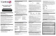
45Loosen <strong>the</strong> screw on <strong>the</strong> heat terminal (typically marked ‘W’ or ‘W1’) <strong>and</strong> secureone end of <strong>the</strong> resistor in <strong>the</strong> HVAC system’s Heat Relay Terminal by tightening <strong>the</strong>terminal screw.Connect <strong>the</strong> o<strong>the</strong>r end of <strong>the</strong> resistor to <strong>the</strong> 24V common return path. Two completedwiring examples are shown below.Example 1. The first example (Figure 8) shows an HVAC system with a dedicated24V Common screw terminal on <strong>the</strong> control board. The resistor simply spans between<strong>the</strong> Heat Relay Terminal (W) <strong>and</strong> <strong>the</strong> Common Terminal, providing a bypassfor some of <strong>the</strong> current that would o<strong>the</strong>rwise pass through <strong>the</strong> heat relay circuit.Figure 8. HVAC with Common Screw TerminalCommon TerminalHeat RelayTerminal (W)Bypass Resistor26
Example 2. This second example (Figure 9) shows a control board that does not provide acommon wire screw terminal. In this example, an additional length of wire was added to <strong>the</strong>resistor which allowed it to connect from <strong>the</strong> ‘W’ terminal to <strong>the</strong> connector for <strong>the</strong> 24V commonthat connects from <strong>the</strong> HVAC transformer to <strong>the</strong> control board.Figure 9. HVAC without a Common Screw TerminalBypass ResistorWire Extension24V CommonHeat RelayTerminal (W)67When <strong>the</strong> bypass resistor is in place, you should re-assemble any covers or housings thatwere removed to access <strong>the</strong> transformer <strong>and</strong> control panel (often, safety switches prohibit<strong>the</strong> HVAC equipment from running until all covers are in place).Restore power to <strong>the</strong> HVAC system <strong>and</strong> test that both heating <strong>and</strong> cooling are functioningcorrectly with <strong>the</strong> resistor in place.27
Sample Wiring ConfigurationsThe next several pages provide sample <strong>Thermostat</strong> connections <strong>and</strong> configurations foryour reference.WARNING! Do not install LINE VOLTAGE wires to a LOW VOLTAGE wire.IMPORTANT! When utilizing power stealing, <strong>Control4</strong> recommends installing <strong>the</strong>included 270 Ohm bypass resistor on <strong>the</strong> HVAC system to minimize any potentialside effects. See <strong>the</strong> previous section “Installing a Bypass Resistor to Enable PowerStealing on a <strong>Wireless</strong> <strong>Thermostat</strong>.”IMPORTANT! Do not install any Remote Temperature Sensors to <strong>the</strong> TS terminalso<strong>the</strong>r than supported external temperature sensors (Flush Mount Remote TemperatureSensor, Aprilaire Model 8051 or Duct/Outdoor Remote Temperature Sensor,Aprilaire Model 8052, etc.). For installation instructions, see your Aprilaire documentation.IMPORTANT! Install <strong>the</strong> U-shaped Terminal jumper wire between RC <strong>and</strong> RH for asingle stage system.28
Wiring ConnectionsTo see which relays are triggered when certain modes of <strong>the</strong> <strong>Thermostat</strong> are calledfor, see “Additional Information” <strong>and</strong> “<strong>Thermostat</strong> Relays” described previously.TerminalRHRCBGY1Y2W1W2OTSTS/CDescription24VAC power for heating—connect to low voltage heating system transformer. (See Note 1 below.)24VAC power for cooling—connect to low voltage cooling system transformer. (See Note 1 below.)Heat Pump—heat changeover valveFan RelayConventional—air conditioner compressorHeat Pump—primary stage relayConventional—2nd stage compressorHeat Pump—2nd stage relayConventional—heat relayHeat Pump—auxiliary heat relayConventional—2nd stage heat relayHeat Pump—emergency heat lineHeat Pump—cool changeover valveRemote sensor (optional accessory)Remote sensor (optional accessory)NOTES:1. Install <strong>the</strong> U-shaped Terminal jumper wire provided between RC <strong>and</strong> RH for a single stage system.2. When connecting <strong>the</strong> common wire, ensure that power stealing is disabled as described in “<strong>Installation</strong>Instructions,” Step 14.3. Refer to <strong>the</strong> table in Step 14 of “<strong>Installation</strong> Instructions” for information about switch settings.29
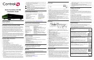
30Figure 10. Conventional, Single Stage Wiring
Figure 11. Conventional, Dual Stage Wiring31
32Figure 12. Heat Pump, Single Stage Wiring
Figure 13. Heat Pump with Electric Auxilliary Heat, Dual Stage Wiring33
34Figure 14. Millivolt Heat, Conventional Cool, Single Stage Wiring
Figure 15. Heat Pump with Electric Auxilliary, Dual Stage, Dual Transformer Wiring35
Regulatory ComplianceTo review regulatory information for your particular <strong>Control4</strong> products, see <strong>the</strong> information located on <strong>the</strong><strong>Control4</strong> website at: http://www.control4.com/regulatory/WarrantyLimited 2-year warranty. Refer to http://www.control4.com/warranty.36