Series Alternator Conversion
Series Alternator Conversion
Series Alternator Conversion
- No tags were found...
You also want an ePaper? Increase the reach of your titles
YUMPU automatically turns print PDFs into web optimized ePapers that Google loves.
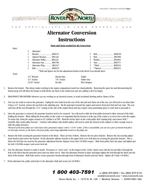
Instructions: <strong>Alternator</strong> KIT:LRNA71707 <strong>Conversion</strong> Instructions Page 1T H E S P E C I A L I S T S I N L A N D R O V E R S • U S AParts:Tools:<strong>Alternator</strong> <strong>Conversion</strong>InstructionsParts and Tools needed for the <strong>Conversion</strong>1 <strong>Alternator</strong>1 Bracket..........................RNE135 1 Bolt.................................RND2501 Adjuster Bracket............RNC446 1 Bolt.................................RNC9081 <strong>Alternator</strong> Pulley............RNC445 1 Washer............................RNA9641 <strong>Alternator</strong> Fan................RNC788 2 Nuts................................RNE4751 <strong>Alternator</strong> Plug...............RNC347 1 **Bolt.............................RND2531 Bolt................................RND251 1 **Spacer.........................RND252**Bolt and Spacer are for the adjustment bracket at the block if not already there.1/2” Wrench Bracket Bar Solder1/2” Socket 7/8” Socket Solder Gun11/16” Socket Pry Bar Wire Stripper1. Remove the bonnet. This always makes working in the engine compartment much less claustrophobic. Removing the spare tire and disconnecting thebonnet prop rod will allow the bonnet to fold all the way back to the windscreen and save pulling it off of its hinges.2. DISCONNECT THE BATTERY whenever you are working on an electrical system, to avoid accidental shorting and/or chance of fire.3. Now you are ready to remove the generator. Unplug the wire leads from the rear of the unit and tuck them out of the way; you will need to use them later.Using a 1/2” wrench, remove the top bolt to the adjusting arm. Tip the generator towards the engine and remove front pivot bolt and rear stud. The rearstud runs all the way through the 2 1/2” casting on the side of the engine block and may require some penetrating spray or some heat to persuade it.4. Once the generator is removed, the generator brackets need to be removed. You will need to slide the front pulley forward to allow removal of the boltsholding the bracket. When sliding the front pulley on the crank, it is important that the keyway is at the top of the crank so as not to lose it into the engine.To insure this, bring the engine around so #1 cylinder is at TDC. Bend the locker back on the crank pulley bolt (starting dog) and remove bolt.*Carefully slide crank pulley forward. (vehicles with military style double pulleys will need to undo the shroud on the radiator to allow enough room toslide the pulley forward.)*Removal of the front pulley nut is best done with a pnuematic impact, with a 1 11/16” socket. If this is unavailable, you can use a pair of channel lock pliers(or thin pipe wrench) on the back or the front pulley, and a large adjustable wrench on the pulley nut.5. Remove the bolts securing the generator bracket to the block. There are four of them. Remove the two-piece bracket. Remove the nut securing adjustmentbracket and remove the bracket. Fit the alternator adjuster bracket to the upper front cover bolt that was securing the generator bracket. This isbelow the bolt that was used for the generator adjustment bracket. Replace lower bolt (18 ft/lbs torque). Slide front pulley back into place and tighten pulleybolt (150 ft/lbs torque) and secure lock tab.6. Now the alternator bracket is ready to install. Put grease or “never seize” on the longest of the 3 bolts, which come with the kit and slide it through thehole in the block that the generator pivot stud was taken out of. Place the alternator bracket in place and finger tighten the bolt through the block into theback of the bracket. Refit bolts used to secure generator bracket through front of alternator bracket and into block. Tighten all 3 bolts (18 ft/lbs).7. Fit the alternator fan, pulley and locker to the alternator shaft and secure nut (36 ft/lbs).1 800 403-7591 or (802) 879-0032 • Fax: (802) 879-9152email@roversnorth.com • www.roversnorth.comRovers North, Inc. • 1319 Vt. Rt. 128 • Westford, Vermont • 05494-9601 USA
Instructions: <strong>Alternator</strong> <strong>Conversion</strong> Page 28. Offer the alternator up to the newly installed bracket. The tabs on the alternator go on the outside of the brackets. Fit the pivot bolts in place, theshorter one in the front and the longer one with the washer, in the rear (see fig.1). The bolts fit from the outside of the brackets only. Secure theadjustment arm to the upper tab of the alternator (see fig. 2). Fit the fan belt around all threeRND251pulleys. Using a pry bar between the alternator and the block, tighten the alternator against thefan belt. The alternator is tight enough when the belt can be pushed 1/4” between the alternatorand the water pump pulleys, securing hardware RNE135(18 ft/lbs)(see fig. 3). Tighten all.9. Take a break; actual installation of alternator iscomplete. Next comes the rewiring.Fig. 2See Fig. 110. Using the existing wiring for the generator, connectthe large wire to one of the two large terminalson the rear of the alternator and the small wire to thesmall terminal on the alternator. This can either bedone directly or by wiring the alternator plug to theend of the generator wiring.11. Disconnect the small wires from the “F” and “D”terminals of the voltage regulator. Connect these twowires together. This is best done by snipping off theconnector ends, stripping the end of the wires andtwisting them together. It should then be eitherwrapped in tape or shrink wrap.RND250RNE475Fig. 1RNC908RNA96412. Disconnect the large wires from the “D” terminal and the “A” and “A1” terminals (labeled “B” on 6cylinder & Military regulators) and connect these wires together as described in step 10.13. Reconnect your battery and turn your ignition on. Your red charge light should come on. If it doesn’t,recheck the connection of the small wire at the alternator and the connection of the two small wires made instep 10.Fig. 314. Make sure all tools and helping hands are clear of the engine. Start the Rover. The charge light shouldgo out and any amp guage or volt meter installed in the vehicle should show a charging state. If not, recheck the large connection at the alternator, theconnection made in step 11 and the connection at the battery. If there is still a problem, call Rovers North. If all is well, refit the bonnet and sparetire, clean up and you are done!


