SOLAR SWITCH - Solar Bazaar
SOLAR SWITCH - Solar Bazaar
SOLAR SWITCH - Solar Bazaar
- No tags were found...

Create successful ePaper yourself
Turn your PDF publications into a flip-book with our unique Google optimized e-Paper software.
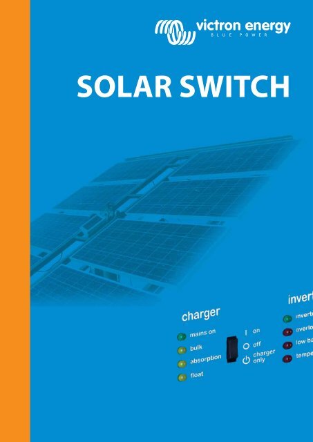
<strong>SOLAR</strong> <strong>SWITCH</strong>
VE <strong>Solar</strong>SwitchNo-break back-up for grid connected solar systemsIntroduction: preventing shut down of the PV system in the event of a power outageA rapidly growing number of houses, farms and other buildings are being fitted with grid connected solar installations. The standard configuration has an importantdrawback: it is dependent on the grid. If the grid fails, the grid connected inverter shuts down and a total blackout is the result, despite the investment in a solarinstallation.The same is true for other grid connected alternative energy solutions, such as wind, water or micro CHP (micro Combined Heat & Power).Basically, the solution to this problem is to add an inverter/charger and batteries.Several configurations are possible.The problem: standard PV system shuts down in case of power outageFigure 1 Standard PV system with two kWh meters used in countries with a feed-in tariff Figure 2 With one kWh meter used in countries without feed-in tariffIn case of a power outage the grid inverter will shut down and the house will be “in the dark”.Grid inverterGrid inverter<strong>Solar</strong> panel<strong>Solar</strong> panelFeed-in meter0 1 9 6 3 4 7,kWhProtected loadsProtected loadsSupply meter0 1 9 6 3 4 7,kWhSupply meter0 1 9 6 3 4 7,kWhPublic gridPublic grid
<strong>SOLAR</strong>CONVERTERThe solutiona Victron MultiPlus or Quattro inverter/charger with <strong>Solar</strong>SwitchFigure 3: Two meter system with MultiPlus and <strong>Solar</strong>SwitchWhen the public grid is available, the Victron <strong>Solar</strong>Switch will connect the solar inverter directly to the grid.If the grid fails, the power from the solar inverter will be redirected to the output of the MultiPlus. The MultiPlus replaces the grid and will balance the powermismatch between the load and the solar inverter. A power shortage will be supplemented by the MultiPlus, discharging the battery, and excess power will be usedto recharge the battery.Once the batteries are fully charged, the excess power can be redirected to a water heater (relay not shown), or a dump load (not shown), or the grid inverter can bestopped by slightly changing the output frequency of the MultiPlus (this is a standard feature of the MultiPlus).In order to prevent the batteries from discharging completely in case of insufficient solar power, some or all loads can be can be shut down with programmablerelays available on the <strong>Solar</strong>Switch (not shown).Figure 3 Two meter system with MultiPlus and <strong>Solar</strong>SwitchGrid converter<strong>Solar</strong> panelFeed-in meter0 1 9 6 3 4 7,kWhVE <strong>Solar</strong> SwitchProtected loadsSupply meter0 1 9 6 3 4 7,kWhUnprotected loadsPublic gridwater heaterBattery• Grid impedanceIn some countries grid impedance measurement is required as an additional safeguard against islanding. The output impedance of the MultiPlus will not matchthe impedance of the grid. Therefore the grid impedance monitoring function of the grid inverter must be switched off for proper functioning of the system. Incountries were grid impedance monitoring is required, an additional grid monitoring module ( available from Victron Energy) must therefore be inserted betweenthe <strong>Solar</strong>Switch and the PV feed-in meter.• Limited grid powerIn case of insufficient grid power to support peak loads, the PowerAssist feature of the MultiPlus can be used to supply additional power, taken from the battery.The batteries will be recharged automatically when excess grid power is available.• Applicable VE inverter/chargersAll models MultiCompact, MultiPlus and Quattro with VEBus interface.All MultiPlus and Quattro models can be configured for parallel and for three phase operation.• PV power rangeThe peak PV power (or wind or other renewable power) fed back into the MultiPlus or Quattro should never exceed the maximum charging power.In case of a MultiPlus 24/3000/70 for example, the maximum charging power is 24V x 70A = 1680W. If the grid inverter “tries” to feed more than 1680W back intothe MultiPlus, not all power can be absorbed and the system will shut down.Figure 4 Alternative ’two + one’ meter system with MultiPlus and <strong>Solar</strong>SwitchGrid inverter<strong>Solar</strong> panelSell back meter0 1 9 6 3 4 7,kWhVE <strong>Solar</strong> SwitchProtected loadsSupply meter0 1 9 6 3 4 7,kWhNet metering0 1 9 6 3 4 7,kWhUnprotected loadsPublic gridwater heaterBattery
Operating modes off on-grid system with <strong>Solar</strong>Switch• A. The grid is presentAll loads are supplied by power from the grid. <strong>Solar</strong> power is directed to the grid.• B. Grid failureThe water heater is disconnected. <strong>Solar</strong> energy is used to supply the protected loads and/or to recharge the batteries.• C. Batteries dischargedAll loads are disconnected. <strong>Solar</strong> energy is used to recharge the battery. The loads will be reconnected after (partial) recharge of the batteries.
Important featuresAfter installation, the MultiPlus or Quattro is ready for use.If settings have to be changed, this can be done in a matter of minutes with a new DIP switch setting procedure. Even parallel and 3-phase operation can beprogrammed with DIP switches: no computer needed!Alternatively, a VE.Net or Blue Power panel can be used instead of the DIP switches.Sophisticated software (VE.Bus Quick Configure and VE.Bus System Configurator) is available to configure several new, advanced, features.Integrated Battery MonitorAt request all Multi’s and Quattro’s can be fitted with an integrated battery monitor.Although less accurate than a standalone battery monitor such as for example our BMV600, the integrated Battery Monitor is the ultimate tool to controla generator, or to control connection to the grid in case of a one meter system without PV back feed into the grid.Features of the Integrated Battery Monitor:• Battery capacity range from 50Ah to 10.000Ah.• Resets battery capacity at 85% charged when absorption stage is reached.(reset is needed to prevent drift in case the generator or the grid is normally disconnected before 100% battery charge is reached)• Resets battery capacity at 100% charged when float stage is reached.• Gives a generator start signal (or closes back feed relay to connect to the grid) at a predetermined battery discharge level.• Gives a generator stop signal (or opens back feed relay to disconnect the grid) after a predetermined time once absorption voltage has been reached.• Automatic battery equalization.Notes:• The Integrated Battery Monitor measures current through the Multi or Quattro only. Any DC battery charge or discharge current from equipment connecteddirectly to the battery is not taken into account.• VEConfigure software is needed for configuration.Quiet period: generator offAn internal clock in the Multi or Quattro allows programming of three quiet periods per day, during which the generator will not be started, unless:• Inverter shutdown due to low battery voltage is imminent.• Battery is discharged beyond a preset level.• Load increases beyond a preset level.Start and stop levels can be set independently for each of the three quiet periods.Using solar power to the maximumA quiet period can also be used to make sure that the battery is sufficiently discharged before an important contribution from renewable power sources is expected,this to prevent ‘wasting’ renewable energy. This can be achieved by allowing a deeper battery discharge level, and by stopping the generator before absorptionvoltage is reached.Programmable relayAll Multi’s and Quattro’s have a programmable relay. The <strong>Solar</strong>Switch has three programmable relays.Application suggestionsLoad disconnect for two meter and one meter on-grid installationsThe programmable relay can be used to control an optional load disconnect contactor, to shed loads before the Multi shuts down due to low battery voltage(see optional load disconnect in previous page). By disconnecting loads before the low DC voltage trip level is reached, the Multi, and therefore also the grid inverter,will continue to operate, allowing the grid inverter to (partially) recharge the battery.Alternatively, one of the two programmable relays of the <strong>Solar</strong>Switch can be used for the same purpose.Generator start/stopThe programmable relay can be set to give a start signal if one or more of the following conditions are met:• Battery % charged drops below a preset value (see integrated battery monitor).• Battery voltage drops below a preset level.• Load increases beyond a preset level (with adjustable time delay).• Battery less than 85% charged shortly before entering a generator quiet period. (this to recharge batteries prior to entering a quiet period)The programmable relay can be set to give a stop signal if:• Battery reaches absorption voltage (with adjustable time delay).• Load decreases below a preset level (with adjustable time delay).• Generator quiet period begins.Using solar power to the maximumIn order not ‘waste’ solar power (or other renewable source), the battery should not be recharged by the grid or a generator just before an important contributionfrom renewable power sources is expected. One or more quiet periods can be used for this purpose.Remote monitoring and control: VGR (Victron Global Remote)The VGR connects either to the GPRS mobile network, or to Ethernet (TCP/IP).Features:• Sends SMS messages to a cellular phone: status and alarms.• Sends data to a user-accessible website. In addition to status and alarms, the website provides graphical display of voltage, current and other important parameters.• SNMP compatible.
Specifications of the <strong>Solar</strong>Switch<strong>Solar</strong>SwitchAC inputs (Mains, MultiPlus/Quattro and <strong>Solar</strong>) Input voltage range: 187-265 VAC Input frequency: 45 – 65 HzMaximum switch through current (A)Maximum power consumption (W)25A< 4WGENERALAuxiliary programmable Relay (3X) (1)Status LEDMax load: 8A 250VAC1 Blue / 1 Yellow / 1 RedCommon Characteristics Operating temp.: -20 to +50°C Humidity (non condensing) : max 95%ENCLOSURECommon CharacteristicsMaterial & Colour: Housing polyamide 6.6 / greenCover unbreakable polycarbonate / TransparentProtection: IP 20230 V AC-connection Screw terminals 5.2mm² (10 AWG)Auxiliary relay connectionScrew terminals 2.5mm² (19 AWG)Weight (grams) 750Dimensions (hxwxd in mm) 88 x 215 x 110STANDARDSSafety EN 60335-1, EN 60335-2-29Emission / Immunity EN55014-1, EN 55014-2, EN 61000-3-31) Three programmable relays Can be programmed with VEConfigure Application examples: Alarm, generator start or load shedding functionAC rating: 230V/4ADC rating: 4A up to 35VDC, 1A up to 60VDCConnecting the <strong>Solar</strong>SwitchGrid inverter<strong>Solar</strong> panel1.Alarm2.Genset start3.Load shedding1. 2. 3.solar programmable relaysmains multi<strong>Solar</strong>SwitchVE.BUSProtected loadsPublic gridUnprotected loadswater heaterBattery
Victron Energy B.V. / De Paal 351351 JG Almere / The NetherlandsPhone: +31 (0)36 535 97 00 Fax: +31 (0)36 535 97 40e-mail: sales@victronenergy.comwww.victronenergy.com