VF-61 Housing - #1956 PN 09-1013 - Velcon Filters
VF-61 Housing - #1956 PN 09-1013 - Velcon Filters
VF-61 Housing - #1956 PN 09-1013 - Velcon Filters
- No tags were found...

Create successful ePaper yourself
Turn your PDF publications into a flip-book with our unique Google optimized e-Paper software.
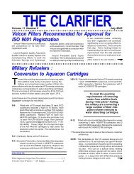
1210 Garden of the Gods Rd., Colorado Springs, CO 8<strong>09</strong>07Phone: (719) 531-5855 FAX: (719) 531-5690e-mail: vfsales@velcon.com / web site: www.velcon.com<strong>VF</strong>-<strong>61</strong>INSTRUCTIONSDESCRIPTIONThe <strong>Velcon</strong> <strong>VF</strong>-<strong>61</strong> filter housing is designed to operate with various Aquacon ® , coalescer,or microfilter elements in a wide variety of applications. The filter housing is shipped withno cartridge installed. Cartridges must be ordered separately. See page 3 for cartridgeselection table.Connections Size: 1- 1 /2" Female NPT<strong>Housing</strong> Pressure Rating: 150 psiNOTE: FOR LIQUID SERVICE ONLY. Do not use or leak test this filter vessel with compressedair or other gases.IMPORTANT SAFETY PRECAUTIONS• To protect the fuel system, including the <strong>VF</strong>-<strong>61</strong> and other components, BE SURE TOINSTALL PRESSURE RELIEF VALVE(S).• MAKE CERTAIN FILTER HOUSING IS COMPLETELY VENTED BEFORE OPENINGHOUSING.• To prevent electrical buildup and discharge - use a grounding wire to place a bondingloop from the drain valve to a point on the metal framework of the vehicle or skid. Thisprovides a continuous bond. Before draining the vessel, electrically bond a metalcontainer to the drain valve using a grounding wire. Then drain the fuel into thebonded metal container.INSTALLATION PROCEDURESInstall the housing at a convenient point in the line. Note “Inlet” and “Outlet” markings on the cast headwhich indicate direction of flow. DO NOT install the housing backwards.NOTE: Fuel “weeping” from the inlet or outlet 1-1/2” NPT connections sometimes occurs when regularpipe dope is used when plumbing the vessel. In time, it appears that the leak is at the clamp. To prevent“weeping”, we recommend a product like Loctite No. 59231 “Pipe Sealant with Teflon ® ”.Install the 1 /2" NPT petcock drain valve which is shipped loose in the shipping carton. Use Teflon ® tapeon the drain valve threads. An optional 1 /2" NPT carbon steel ball valve, part number 554Y020, isavailable at extra cost.Provide room for the housing shell to clear the cartridge during change-out.It is good practice to install a differential pressure gauge so that the differential pressure across thehousing can be monitored. This allows accurate determination of when the cartridge should be changed.© 2011 <strong>Velcon</strong> <strong>Filters</strong>, LLC-1- 1956-R8 05/08P/N <strong>09</strong>-<strong>1013</strong>
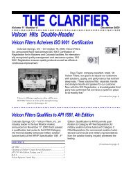
Part number 10678, as described on Form 1715 (<strong>PN</strong> <strong>09</strong>-880) is a differential pressure gauge specificallydesigned to be used on <strong>VF</strong>-<strong>61</strong>.FOR Aquacon ® CARTRIDGES USED IN AVIATION FUEL OR DIESEL FUEL SERVICE, ALWAYSINSTALL A DIFFERENTIAL PRESSURE GAUGE OR OTHER MEANS OF DETERMINING THEDIFFERENTIAL PRESSURE. For diesel fuel service, flow rate should be kept between 15 and 50gpm. Consult <strong>Velcon</strong> for other flow applications.On systems where pressures can exceed 75 psi, a pressure bypass around the pump should be installedto protect the cartridge and the system from a high pressure shock or sudden cartridge seal-off due to aslug of water in the product.Valves ahead of and behind the housing may be required to isolate it during cartridge change-out.CARTRIDGE CHANGE-OUT INFORMATIONFor OS Series Fuel Service – NOTE: The OS Series coalescer cartridge has an O-ring at the bottom ofthe cartridge. This O-ring seals to the inside of the housing. The cartridge fits tightly into the bowl andwill require fuel or oil pre-lubrication to insert into the bowl.** DRAIN SUMP AT EVERY FUELING. **Replace the cartridge when the differential pressure exceeds 15 psi, after 1 year of service, when theflow is significantly reduced, or if differential pressure has been steadily climbing and then begins todecrease – whichever occurs first. After changing cartridges circulate flow through vessel for atleast 3 minutes, use millipores to check for fibers and also check hose end strainers.For Aviation Fuel Service – Please refer to cartridge Operating Procedures that are supplied with eachcartridge shipment.For All Other Applications – Replace the cartridge when the differential pressure exceeds 25 psi, after1 year of service, when the flow is significantly reduced, or if differential pressure has been steadilyclimbing and then begins to decrease – whichever occurs first.CARTRIDGE CHANGE-OUT INSTRUCTIONSREMINDER: Be sure equipment is properly bonded before and after cartridge change-out isperformed.1. Turn off pump.2. Close isolation valves (if any) and open the valve vent at the top.3. Place a bucket under the housing to contain any spilled liquid.4. Drain all liquid from the housing through the bottom drain.5. Loosen the four bolts and rotate out and down to clear the top clamp. Drop the housing shell. Removethe spent cartridge.6. Wipe the inside of the shell clean of any contaminants.7. Inspect the O-ring and replace if damaged. Lightly lubricate the O-ring with the fuel or oil in which itwill be used, and position it on the head.8. Lightly lubricate the cartridge O-rings with the fuel or oil in which it will be used.9. Install a new element onto the nozzle of the filter head. Twist and push the cartridge until it bottomsagainst the step on the nozzle.10. Lift shell up to the housing head, making sure the head O-ring is in place. Align shell bolts so theydo not interfere with inlet and outlet piping. Rotate bolts over clamp top half (see photo).Due to <strong>Velcon</strong> <strong>Filters</strong>, LLC continuing product improvement, drawings, specifications, and pictures are subject to change withoutnotice. For information on recycling used filters, contact FILCare, 719-499-1379
Tighten all bolts to 33 ft-lbs, alternating in a criss-cross fashion.Note: Small O-rings on bolts do not seal, but just hold washersnext to bolt head.11. Close the drain valve, and open isolation valves.12. Open vent valve so that the vessel slowly bleeds air from the top vent whilefilling the housing .13. Close the vent when the housing has filled. Check all fittings and the head/shell junction for leaks.REPLACEMENT PARTSThe <strong>VF</strong>-<strong>61</strong> is shipped with a Buna-N O-ring installed. Some fuels, especially unleaded gasoline, maycause excessive swelling of the O-ring. If this is a problem, a Viton O-ring should be used. Whenordering replacement O-rings from <strong>Velcon</strong>, specify:G-<strong>09</strong>86 for Buna-N or G-<strong>09</strong>86A for VitonReplacements can also be obtained from any commercial supplier of O-rings. Specify size 2-257 in thedesired material.TYPECARTRIDGE SELECTION TABLEMODELNUMBERDEGREE OFFILTRATIONCOLLAPSESTRENGTHAPPLICATIONPleatedMedia(Dirt RemovalOnly)®A quaconMedia*(Dirt & WaterRemoval)Coalescer(Dirt & WaterRemoval)FO-512PL1/2FO-512PL05FO-512PL25AC-51205AD-51225ACO-51201LASL-51201OS-51288OS-512860.5micron75psiFuels, Oils5 microns75psiFuels, Oils25microns75psiFuels, Oils5 microns75 psiOils, MotorGasoline25microns75psiOils, Diesel Fuel0.5micron75psiJet Fuel & Avgas1 micron75psiSolvents0.5microns75psiJet Fuel & Avgas5 microns75psiDiesel*CAUTION: Do not use Aquacon ® cartridges withpre-mixed jet fuel containing anti-icing additives.*WARNING: Aquacon ® cartridges will not remove water from fuel containingalcohol-blending agents (commonly called gasohol). For removal of solids,please use <strong>Velcon</strong> particle removal filters specifically made for gasohol.Consult your <strong>Velcon</strong> representative.© 2011 <strong>Velcon</strong> <strong>Filters</strong>, LLC-3- 1956-R8 05/08P/N <strong>09</strong>-<strong>1013</strong>