installation & operating manual - Duo-Aire
installation & operating manual - Duo-Aire
installation & operating manual - Duo-Aire
- No tags were found...

Create successful ePaper yourself
Turn your PDF publications into a flip-book with our unique Google optimized e-Paper software.
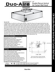
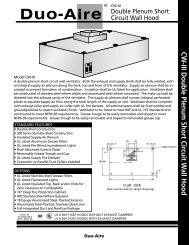
INSTALLATION INSTRUCTIONSInstallation Requirements For All <strong>Duo</strong>-<strong>Aire</strong> Hoods<strong>Duo</strong>-<strong>Aire</strong> hoods are provided with slotted hanging brackets designed to receive 1/2" threaded rodwith a 1/2" bolt and washer. Supporting rods must be connected to all factory installed brackets.Recommended hanging height is 6'- 6" above finished floor for canopies. Low side wall ventilatorsshould be installed directly upon a <strong>Duo</strong>-<strong>Aire</strong> base or on a fire rated wall. If wall mounted, the bottom ofthe vent should be 36" above finished floor.ALL DUO-AIRE VENTILATION SYSTEMS MUST BE INSTALLED IN ACCORDANCE WITH NFPA-96,REMOVAL OF SMOKE AND GREASE-LADEN VAPORS FROM COMMERCIAL COOKING EQUIP-MENT.CANOPIES1. Check all local codes prior to <strong>installation</strong>. Special requirements may be necessarydepending upon building material construction.2. Move crated hood to location of <strong>installation</strong> and very carefully uncrate hood.3. Raise hood to proper hanging height.4. Suspend hood from adequate roof supports using 1/2" threaded rods with nutsand washers. (See Fig. 1)5. Level hood left to right and front to back.6. Brackets are provided for hoods which are to be installed end to end or back toback. Bolt brackets together using 3/8" bolt through holes provided. (See Fig. 2)7. Install “C” channel where the ends of hood meet and install “T” moldings on frontface of hoods where they join. High temperature silicone can be used to install “C”and “T” moldings. (See Fig. 3)8. For Make-up air hoods, the supply collar with built-in U.L. listed fire damper, and air volume damper mustbe installed per instructions on collar.9. Provide a removable service door in supply duct near fire damper. (See Fig. 5)Fig.1Page 2
LOW SIDE WALL VENTILATORS1. Check all local codes prior to <strong>installation</strong>. Special requirements may be necessarydepending upon building material construction.2. Move crated hood to location of <strong>installation</strong> and very carefully uncrate vent.3. If vent is base mounted, base must be installed and leveled front to back and left toright.4. Place vent on base. Secure vent to base by screwing side walls of vent to base. (See Fig. 4)5. If vent is wall mounted, place vent on wall, level front to back and left to right, thenbolt metal hanging bracket located on top of hood to wall. (See Fig. 4)6. Bottom of ventilator should be 36" above finished floor. (See Fig. 5)7. Fluid weld exhaust duct to hood exhaust duct collar. (See Fig. 5)8. For Make-up air ventilators, the supply collar with built-in U.L. listed fire damper, and airvolume damper must be installed per instructions on collar.9. Attach air supply duct work to supply collar. DO NOT SCREW INTO FIREDAMPER.10. Provide a removable service door in supply duct near fire damper. (See Fig. 5)** WHEN USING FLOOR FRYERS,CONFIRM FLUE HEIGHTPage 3
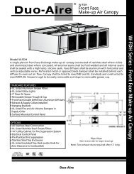
FRESH AIR SUPPLY FAN1. Check all local codes prior to <strong>installation</strong>.2. Supply fan inlet must be located a minimum 10'-0" from the exhaust fan. If 10'-0" isnot possible a 3' vertical separation may be acceptable*.3. Cut and seal supply fan curb to roof.4. Duct shall be constructed of 22 or 24 gauge steel. Insulated duct material shouldbe used to eliminate frost and/or condensation.5. Duct shall be sized to provide air velocities not exceeding 1200 FPM.6. A volume control damper, provided in the duct just above the supplycollar that contains the U.L. listed fire damper, should be properly set to supply CFMrequired.7. If the hood is provided without the supply collar installed, it must be installed perthe instructions provided on the collar.8. Carefully place the supply fan on roof curb. Face supply fan inlet away fromprevailing winter wind. Electrical back draft damper is recommended in cold climates.9. Bolt or screw fan to fan curb.10. Make all necessary electrical connections and check fan for proper rotation.“NOTE”: Fan will supply air running in wrong direction.* Dependent on local code requirements.Fig. 7Page 6
HOOD WITH AIR VOLUME CONTROLLERSSome <strong>Duo</strong>-<strong>Aire</strong> canopy hoods will be designed with our patented Air Volume Controllers(AVC) located directly behind the standard filter bank. The AVC are specially designed toexhaust high volumes of air over high heat - high grease producing equipment and low volumesof air over low heat - low grease producing equipment thereby reducing the totalexhaust volume.The AVC were factory set, based on the cooking equipment specified on the approveddrawings, therefor the AVC will not have to be adjusted. If, however, the cooking equipmenthas changed or should change in the future, the following procedure should be followed.AVC ADJUSTMENT INSTRUCTIONS1. Remove all grease filters from the hood.2. Loosen retaining screws on channels holding the AVC at each end.3. Slide AVC up or down as needed. The higher the AVC is moved the greater will bethe exhaust volume.4. Reset the retaining screw at the desired position.5. Replace grease filters.Page 7
INSTALLATION OF SIDE SKIRTSPieces ProvidedOne or two optional side skirts may be provided.INSTALLATION1. Side skirts are off set at the top and have a 90˚ bend inward at the rear.2. Skirts are to overlap the outside of the hood. Bolts and acorn nuts should be attached perthe drawing. (Stainless bolts & acorn nuts supplied).3. Skirt flange should be screwed to the wall (screws not provided).Page 8
TOP ENCLOSURESINSTALLATION OF ENCLOSURE PANELSPieces ProvidedEnclosure panels are provided for exposed ends and front of hood(s).INSTALLATION INSTRUCTIONS1. Hoods ordered with enclosure panels will be shipped with threaded metal studs installed onperimeter of hood top where panels are to be installed. Retaining nuts and washers areinstalled on the studs prior to shipping.2. Loosen nuts on studs. Slide enclosure panel under loosened nuts. Holes in panels are openon end so nuts do not have to be removed.3. If enclosure panels are installed on one or more hoods butted end to end, the butting endsof the front enclosure panels should be bolted together.Page 9
INSTALLATION OF INSULATED STAINLESS STEEL WALL PANELSPieces ProvidedInsulated wall panel comes in two pieces. Each piece will be the same length as the hood.A. Top panel will have a 1" flange full length top and bottom and, interlocking slots located onthe bottom.B. Bottom panel will have interlocking tabs on top and full length 1" flange on bottom.INSTALLATION INSTRUCTIONS FOR INSULATED WALL PANEL ( See Fig. 13)1. Install wall panels prior to hanging hood(s).2. Install top panel first. Top of panel should be installed 6'-6" A.F.F. and level. Screw panel towall making sure slotted holes are facing floor.3. Install lower panel by sliding tabs into slotted holes in upper panel, screw bottom flange towall.4. Caulk horizontal seam with NSF approved silicone sealant.5. When hood is hung it will rest on top panel.NOTE: be careful not to damage wall panel face when installing hood.INSTALLATION INSTRUCTIONS FOR SINGLE THICKNESS WALL PANEL ( See Fig. 14)1. Install wall panels prior to hanging hood(s).2. Install seam strips at proper locations and screw to wall.3. Apply glue to wall between seem strips.4. Slip one end of wall panel into seam strip, pull out middle of panel and slip other end of panelinto other seam strip. Gently apply pressure over entire wall panel to secure to wall.Page 10
START - CHECK - BALANCEDIRECT DRAW HOODS1. Close all doors and windows.2. Operate all exhaust fans, Make-up air unit and building HVAC.3. Turn on all cooking equipment under the hood to preheat to <strong>operating</strong>temperature.4. Produce large quantities of smoke.5. Observe capture of vapors.6. If all vapors are not captured, increase exhaust fan RPM.7. Check air pressure in kitchen. Pressure must be negative relative to dining roompressure.8. Air velocities entering the kitchen from the dinning room should not exceed 100FPM. No air should be moving toward the dining area.9. Repeat steps 6 and 7 until all vapors are captured.NOTE:The exhaust and supply (if any) air flow rates were established under controlledlaboratory conditions, and greater exhaust and/or lesser supply air may berequired for complete vapor and smoke removal in specific <strong>installation</strong>sPage 11
START - CHECK - BALANCEMAKE-UP AIR HOODSEXHAUST FAN(S)1. Open all doors and/or windows leading to outside.2. Start the exhaust fan only. Do not run the supply fan or Make-up air unit.3. Refer to <strong>Duo</strong>-<strong>Aire</strong> drawings and/or U.L. information label on hood forproper FPM and CFM requirements.4. Adjust speed of exhaust fan to obtain proper air velocities and CFM throughgrease filters.SUPPLY FAN OR MAKE-UP AIR UNIT1. Start the supply fan and/or Make-up air unit only. Do not run the exhaust fan.2. Refer to <strong>Duo</strong>-<strong>Aire</strong> drawings or U.L. information label on hood for properFPM and CFM requirements.3. Adjust speed of blower to obtain proper air velocities and CFM through Make-upair outlet(s).FINAL AIR BALANCEMAKE-UP AIR HOODS1. Close all doors and windows.2. Operate all exhaust fans, supply fans, make-up air unit and building HVAC system.3. Turn on all cooking equipment under the hood and preheat to <strong>operating</strong>temperature.4. Produce large quantities of smoke or steam.5. Observe capture of vapors.6. If all vapors are not totally captured, fine tune the system by adjusting the airvolume control damper installed in the supply collar. Slightly reduce the amount ofsupply air directed under the hood until full capture is obtained.7. Check total pressure in building. Pressure should not exceed .02 negative pressure.Page 12
AIR BALANCE REPORTEXHAUST FANSFan No. Designed RPM Actual RPM Designed CFM Actual CFM12345Total ExhaustSUPPLY FANSFan No. Designed RPM Actual RPM DesignedCFM Actual CFM1234Total SupplyHVAC SYSTEMUnit No. Designed RPM Actual RPM Designed CFM Actual CFM Outside Air CFM123Total Outside AirPage 13
NOTES AND WORKSHEET4000 Portage Road, Suite 205/206, Kalamozoo, MI 49001 Phone (616) 343-2475 Fax (616) 343-2438