
You also want an ePaper? Increase the reach of your titles
YUMPU automatically turns print PDFs into web optimized ePapers that Google loves.
<strong>Alibre</strong> <strong>Design</strong> <strong>–</strong> <strong>Modeling</strong> <strong>Fundamentals</strong><br />
<strong>Alibre</strong> <strong>Design</strong> <strong>–</strong> <strong>Modeling</strong> <strong>Fundamentals</strong><br />
Introduction<br />
<strong>Alibre</strong> <strong>Design</strong> is a parametric solid modeling system. Parametric solid modeling involves the<br />
application of dimensions and other parameters to define a 2D profile, and ultimately the 3D<br />
shape, of a part. These dimensions and parameters can be changed at anytime to easily<br />
modify designs and alter the shape of a model.<br />
Parts are comprised of one or more features. A feature represents an individual shape and can<br />
either add material or remove material in a part. Examples of features include holes, fillets,<br />
cuts, and revolutions.<br />
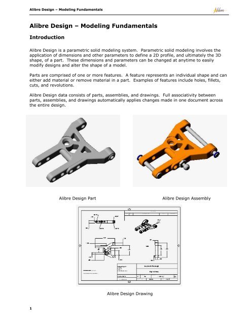
<strong>Alibre</strong> <strong>Design</strong> data consists of parts, assemblies, and drawings. Full associativity between<br />
parts, assemblies, and drawings automatically applies changes made in one document across<br />
the entire design.<br />
1<br />
<strong>Alibre</strong> <strong>Design</strong> Part <strong>Alibre</strong> <strong>Design</strong> Assembly<br />
<strong>Alibre</strong> <strong>Design</strong> Drawing
<strong>Alibre</strong> <strong>Design</strong> <strong>–</strong> <strong>Modeling</strong> <strong>Fundamentals</strong><br />
� You typically start a new part by first creating a sketch, which is a 2D profile of a 3D<br />
shape. The sketch will subsequently be used to create a base feature, always the first<br />
feature you create in a part. You can add as many additional features as necessary to<br />
fully define a part.<br />
� You can easily change the shape of a model by adding, deleting, editing, or reordering<br />
features.<br />
� You can generate 2D mechanical drawings at any time in the design process based on<br />
information in parts and assemblies.<br />
� You can also import parts, assemblies, and drawings from other CAD systems into<br />
<strong>Alibre</strong> <strong>Design</strong>. You can modify imported parts and assemblies or you can add new<br />
features to them.<br />
Workspaces<br />
All design work in <strong>Alibre</strong> <strong>Design</strong> is done in windows called workspaces. You can open a part,<br />
assembly, drawing, or bill of materials (BOM) workspace. Each workspace is displayed in a<br />
separate window; however, a drawing workspace can contain multiple drawing sheets. You can<br />
have as many workspaces open as needed.<br />
Opening a New Workspace<br />
To open a new part, drawing, assembly, or BOM workspace:<br />
1 On the Home window, from the File menu, select New.<br />
2 Select Part, Assembly, Drawing, or Bill of Materials.<br />
Or<br />
Click the new Part, Assembly, Drawing, or Bill of Materials workspace icon on the<br />
Home window main toolbar.<br />
Workspace Terms<br />
<strong>Alibre</strong> <strong>Design</strong> workspaces are divided into two distinct areas.<br />
� The <strong>Design</strong> Explorer (in part and assembly workspaces) and the Drawing Explorer<br />
(in drawing workspaces) are located on the left side of the workspace and list all<br />
pertinent design information.<br />
� The work area is the graphics canvas in which you create all parts, assemblies and<br />
drawings. Toolbars may be located above and to the right of the work area.<br />
2
<strong>Alibre</strong> <strong>Design</strong> <strong>–</strong> <strong>Modeling</strong> <strong>Fundamentals</strong><br />
Model Terms<br />
3<br />
Model<br />
Toolbars<br />
<strong>Design</strong><br />
Explorer Work Area<br />
Part Workspace with default toolbars<br />
The following terms are consistently used throughout the documentation and refer to geometric<br />
elements in a model (faces, edges, and vertices) as well as construction geometry (reference<br />
planes, axes, and the origin).<br />
Origin<br />
Edge<br />
Reference Plane<br />
Axis<br />
Face<br />
Vertex
Work Area Background Color<br />
<strong>Alibre</strong> <strong>Design</strong> <strong>–</strong> <strong>Modeling</strong> <strong>Fundamentals</strong><br />
You can change the work area background color in a part or assembly workspace. To change<br />
the background color:<br />
1 In a part or assembly workspace, from the Tools menu, select Options.<br />
2 Select the Color Scheme tab in the Options dialog box.<br />
3 Choose one of the four predetermined color schemes, e.g. Dark Background<br />
Scheme, from the dropdown list.<br />
Or<br />
Select a custom background color.<br />
4 Click OK to apply the setting.<br />
Multiple Views<br />
You can split the work area into as many as four different views. You can zoom, rotate, and set<br />
the view mode in each view independently.<br />
To split the work area into multiple views:<br />
1 In a workspace, from the Window menu, select Split View.<br />
2 Select Horizontal, Vertical, or Both. The Horizontal and Vertical options split the<br />
work area into two views. The Both option splits the work area into four views.<br />
To select a view and make it active, click anywhere in the view border. A red arrow appears in<br />
the upper right corner of the active view.<br />
4
<strong>Alibre</strong> <strong>Design</strong> <strong>–</strong> <strong>Modeling</strong> <strong>Fundamentals</strong><br />
Named Views<br />
In part and assembly workspaces, you can use named views to control view display and<br />
manipulation. You can quickly change the display to a default view and add custom views using<br />
the Orientations command under the View menu or by selecting the View Orientations<br />
tool on the View toolbar.<br />
To apply a named view to the work area, double-click a named view, or select a named view<br />
and then click Set.<br />
You can also add a custom view orientation by clicking Add and subsequently entering a view<br />
name.<br />
Default views are listed in blue, and custom views are listed in black.<br />
<strong>Design</strong> Explorer<br />
As previously described, each part and assembly workspace consists of the work area and the<br />
<strong>Design</strong> Explorer. The <strong>Design</strong> Explorer’s primary purpose is to track and list the structure of a<br />
part or assembly. However, the <strong>Design</strong> Explorer can be used to accomplish numerous tasks.<br />
Use the <strong>Design</strong> Explorer to:<br />
5<br />
� Select items in the design by name.<br />
� Suppress or hide selected features and parts.<br />
� Hide planes and axes.<br />
� Temporarily roll the model or assembly back to an earlier state:<br />
double-click a feature or part or use the rollback bar.<br />
� Identify and change the order in which features are regenerated.<br />
� Rename features: right-click a feature and select Rename.<br />
� Delete features and parts.<br />
� Toggle the display of section views on and off.<br />
� Edit a sketch: double-click the sketch name.
� Track and control the display of redline markups.<br />
� Check the status of a feature or part to resolve errors.<br />
Selection Methods<br />
<strong>Alibre</strong> <strong>Design</strong> <strong>–</strong> <strong>Modeling</strong> <strong>Fundamentals</strong><br />
The majority of design tasks require that an item is selected. For example, a reference plane or<br />
planar face must be selected before you can begin sketching.<br />
� Normal selecting <strong>–</strong> To select faces, edges, vertices, etc., first click the Selection tool<br />
or choose Select from the View menu. Move the cursor over an item, then click<br />
once to select the item. An item will change to red as you move the cursor over it and<br />
will change to yellow after you select it<br />
Note: Selection highlight colors will vary depending on the work area color scheme<br />
used. This documentation describes properties associated with the Dark Background<br />
Scheme.<br />
� Selecting Multiple Items <strong>–</strong> To select multiple items, hold the Shift key while you<br />
select the items.<br />
� Selecting by Dragging <strong>–</strong> In a sketch or drawing, select multiple items by dragging a<br />
selection rectangle around a group of items.<br />
� Using a Selection Filter <strong>–</strong> Apply a filter to make selecting a specific item type easier.<br />
Filter on Features, Faces, Edges, and/or Vertices. To apply selection filter, from the<br />
Tools menu, expand Selection Filters and choose the appropriate filter. You can also<br />
activate the Selection Filters toolbar and control filters easily with icons.<br />
� Face, Edge, and Vertex Cursors <strong>–</strong> As you move the cursor over faces, edges, and<br />
vertices, the cursor will change to provide a visual indication of the item type.<br />
Vertex Selection Edge Selection Face Selection<br />
� Modifying a Selection <strong>–</strong> Many dialog boxes require a selection or multiple selections in<br />
order to complete the command. The selected item name will often populate an area in<br />
a dialog box. To change the selection, either make another selection, which will override<br />
the previous selection, or right-click the item name in the dialog box, and choose Clear<br />
Selections or Remove Selected Item(s).<br />
� Advanced Selector <strong>–</strong> On occasion, other items may obscure the item you want to<br />
select. Use the Advanced Selector to accurately select an item. To use the Advanced<br />
Selector, move the cursor over the item and click the right-click. The Select dialog box<br />
appears containing all the items in the vicinity. Select the item you want from the list.<br />
6
<strong>Alibre</strong> <strong>Design</strong> <strong>–</strong> <strong>Modeling</strong> <strong>Fundamentals</strong><br />
7<br />
Note: If available, you can also click the middle mouse button to access the Advanced<br />
Selector.<br />
� Selecting from the <strong>Design</strong> Explorer <strong>–</strong> Select any item in the <strong>Design</strong> Explorer by<br />
clicking the item name. The associated item will change color in the work area. Select nonconsecutive<br />
items in the <strong>Design</strong> Explorer by holding down the Ctrl key as you click. Select<br />
consecutive items in the <strong>Design</strong> Explorer by holding down the Shift key as you click.<br />
Toolbars<br />
You can control toolbar visibility as well as toolbar position in a workspace.<br />
To turn toolbars on and off:<br />
1 In any open workspace, from the View menu, select Toolbars. The Toolbars dialog box<br />
appears.<br />
2 To hide a toolbar that is currently displayed, click the checked box next to the toolbar<br />
name.<br />
3 To display a toolbar, click the empty check box next to the toolbar name.<br />
4 Click OK to apply changes.<br />
To move a toolbar between the top and right of the workspace:<br />
1 In any open workspace, from the View menu, select Toolbars. The Toolbars dialog box<br />
appears.<br />
2 To move a toolbar from the top of the workspace to the right of the workspace, select<br />
the toolbar name and then click Right.
<strong>Alibre</strong> <strong>Design</strong> <strong>–</strong> <strong>Modeling</strong> <strong>Fundamentals</strong><br />
3 To move a toolbar from the right of the workspace to the top of the workspace, click the<br />
toolbar name and then click Top.<br />
4 Click OK to apply changes.<br />
To drag a toolbar to a different position in an area:<br />
1 Move the cursor near the vertical bar on the left side of the toolbar.<br />
2 Click and hold the mouse button and drag the toolbar to a new position within its<br />
respective area.<br />
View Manipulation<br />
You can change the perspective and orientation of the work area view by using the rotate,<br />
zoom, and pan tools. These tools are available from the View toolbar and the View menu.<br />
� The Pan tool dynamically moves the current view around the work area. Click the<br />
icon and then click and drag the cursor around the work area.<br />
Note: You can also pan by holding the Shift key and the left and right mouse buttons<br />
down simultaneously while moving the cursor around the work area.<br />
� The Rotate tool dynamically rotates a part or assembly around a given point. Click<br />
the icon and then click and drag the cursor around the work area.<br />
Note: You can also rotate by holding the left and right mouse buttons down<br />
simultaneously while moving the cursor around the work area.<br />
� The Zoom Mode tool dynamically changes the scale of the work area view. Click<br />
the icon, hold the left mouse button down, and move the cursor up to zoom in, or down<br />
to zoom out.<br />
Note: If available, you can use the mouse wheel to dynamically zoom in and out.<br />
� The Zoom to Window tool changes the scale of the view so that a specified region<br />
fills the work area. Click the icon, click and drag a rectangle around an area with the<br />
cursor. Release the mouse button when the rectangle borders the correct area.<br />
� The Zoom to Fit tool restores the view so that the entire design is displayed in the<br />
work area.<br />
� The Previous View tool reorients the work area to views that preceded the current<br />
view. The Next View<br />
used.<br />
tool becomes available after the Previous View tool has been<br />
� The Orthographic tool changes the display of the work area so that parallel edges,<br />
faces, etc. appear as infinitely parallel.<br />
8
<strong>Alibre</strong> <strong>Design</strong> <strong>–</strong> <strong>Modeling</strong> <strong>Fundamentals</strong><br />
9<br />
� The Perspective tool changes the display so that all parallel edges, faces, etc.<br />
appear to converge into one point.<br />
� The Wireframe tool changes the display so that only the edges of the model are<br />
shown.<br />
� The Shaded tool changes the display so that the faces of the model are shaded.<br />
� The View Orientations tool stores default views (e.g. front, back, left, etc.) as well<br />
as custom views.<br />
� The Rotation Points tool stores default rotation points (the origin, model’s center of<br />
mass and center of volume) as well as custom rotation points.<br />
Getting Help<br />
Help can be accessed numerous ways while you are using <strong>Alibre</strong> <strong>Design</strong>.<br />
� While online, you can access the Help system from any window with the Help menu or<br />
the F1 key.<br />
� You can also install the Help system locally off so that Help is available when you are<br />
working offline. You may install Help from the CD or the <strong>Alibre</strong> support web site,<br />
www.alibre.com/support.<br />
� Seven help modules related to basic functionality are accessible on the Home window in<br />
the Welcome tab. Click one of the seven links in the How Do I section to access these<br />
help modules.<br />
� To access help related to a specific dialog box, click the Help button in the dialog box.<br />
� When you mouse over an icon on a toolbar, a Tooltip will popup that identifies the<br />
function of the tool.<br />
� The status bar in the lower left corner of a workspace displays hints related to<br />
completing a command and provides a brief description of a tool or function.<br />
� While online, you can contact the <strong>Alibre</strong> Assistant from the Contacts list in the Home<br />
window. You can send messages, emails, start a chat conversation, and work in a Team<br />
<strong>Design</strong> session in real-time to ask technical questions and resolve issues. The <strong>Alibre</strong><br />
Assistant is available from 8:00 am to 5:00 pm Central Time.<br />
� New documentation materials including tutorials will be available periodically on the<br />
<strong>Alibre</strong> website, www.alibre.com, in the Support section. In order to access the<br />
materials, you must first sign into the web site. Check frequently for updates.