Designing A Wood Railing With Cable as an In-Fill.
Designing A Wood Railing With Cable as an In-Fill.
Designing A Wood Railing With Cable as an In-Fill.
- No tags were found...

Create successful ePaper yourself
Turn your PDF publications into a flip-book with our unique Google optimized e-Paper software.
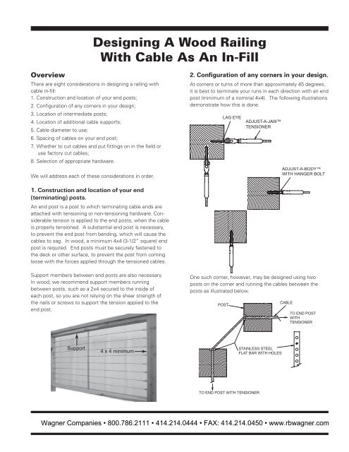
<strong>Designing</strong> A <strong>Wood</strong> <strong>Railing</strong><strong>With</strong> <strong>Cable</strong> As An <strong>In</strong>-<strong>Fill</strong>OverviewThere are eight considerations in designing a railing withcable in-fill:1. Construction <strong>an</strong>d location of your end posts;2. Configuration of <strong>an</strong>y corners in your design;3. Location of intermediate posts;4. Location of additional cable supports;5. <strong>Cable</strong> diameter to use;6. Spacing of cables on your end post;7. Whether to cut cables <strong>an</strong>d put fittings on in the field oruse factory cut cables;8. Selection of appropriate hardware.2. Configuration of <strong>an</strong>y corners in your design.At corners or turns of more th<strong>an</strong> approximately 45 degrees,it is best to terminate your runs in each direction with <strong>an</strong> endpost (minimum of a nominal 4x4). The following illustrationsdemonstrate how this is done.We will address each of these considerations in order.1. Construction <strong>an</strong>d location of your end(terminating) posts.An end post is a post to which terminating cable ends areattached with tensioning or non-tensioning hardware. Considerabletension is applied to the end posts, when the cableis properly tensioned. A subst<strong>an</strong>tial end post is necessary,to prevent the end post from bending, which will cause thecables to sag. <strong>In</strong> wood, a minimum 4x4 (3-1/2” square) endpost is required. End posts must be securely f<strong>as</strong>tened tothe deck or other surface, to prevent the post from comingloose with the forces applied through the tensioned cables.Support members between end posts are also necessary.<strong>In</strong> wood, we recommend support members runningbetween posts, such <strong>as</strong> a 2x4 secured to the inside ofeach post, so you are not relying on the shear strength ofthe nails or screws to support the tension applied to theend post.One such corner, however, may be designed using twoposts on the corner <strong>an</strong>d running the cables between theposts <strong>as</strong> illustrated below.Wagner Comp<strong>an</strong>ies • 800.786.2111 • 414.214.0444 • FAX: 414.214.0450 • www.rbwagner.com
A stainless steel flat bar (<strong>Cable</strong> Support) with holes for thecable to p<strong>as</strong>s through is mounted on each surface wherethe cable enters or exits the post at <strong>an</strong> <strong>an</strong>gle, to prevent thecable from biting into the wood when it is tensioned.<strong>Cable</strong> Supports are available from the factory (see the <strong>Wood</strong>Accessories section of this publication for order information).We do not recommend using this type of corner post configurationon more th<strong>an</strong> one corner between <strong>an</strong>y two-endposts (with tensioning hardware). When using this configuration,you will need tensioning hardware on both ends ofthe run, <strong>an</strong>d you will need to tension the cables from bothends.On a turn of less th<strong>an</strong> approximately 45 degrees, you c<strong>an</strong>run your cables through a single post, but you will still needto use a <strong>Cable</strong> Support where the cable enters or exits thepost at <strong>an</strong> <strong>an</strong>gle, to prevent the cable from biting into thewood when it is tensioned.See No. 8. Selection of appropriate hardware below for otherhardware combinations that c<strong>an</strong> be used on corner posts.4. Location of additional cable supports.Regardless of the amount of tension you apply to the cables,there will be some flex in the cable when it is installed.When the cables are spaced vertically on your end post <strong>as</strong>we recommend below (see No. 6 Spacing of cables on yourend post), we recommend that the cable be supported insome m<strong>an</strong>ner no more th<strong>an</strong> every 42” along its run, to meetcode requirements that a 4” sphere c<strong>an</strong>not p<strong>as</strong>s through thecables.As indicated above, this support c<strong>an</strong> be provided with intermediateposts or a lighter material acting <strong>as</strong> a cable brace.As with <strong>an</strong> intermediate post, a cable brace also runs betweenthe top rail <strong>an</strong>d the lower mounting surface, but itspurpose is only to support the cable. It is not intended tobe <strong>an</strong> element providing structural support to the railing.<strong>Cable</strong> braces c<strong>an</strong> be much thinner <strong>an</strong>d, therefore, lessobtrusive th<strong>an</strong> posts, <strong>as</strong> their primary purpose is only tosupport the cable.3. Location of intermediate posts.<strong>In</strong>termediate posts (or mid-posts) are placed between endposts. An intermediate post runs from the top rail to thelower mounting surface <strong>an</strong>d is a structural element.<strong>In</strong>termediate posts should be placed at intervals betweenend or corner posts <strong>as</strong> frequently <strong>as</strong> necessary to meetbuilding code requirements. An engineer or design professionalshould be engaged, if you are unable to otherwisedetermine intermediate post spacing.<strong>Cable</strong> is strung through holes drilled in the intermediateposts, so intermediate posts also become supports for thecable between end posts.<strong>With</strong> cable spaced vertically on centers <strong>as</strong> recommendedbelow (see No. 6 Spacing of cables on your end post below),we recommend that the cable be supported in some m<strong>an</strong>nerno more th<strong>an</strong> every 42” along its run. The support c<strong>an</strong>be provided by <strong>an</strong> intermediate post or it c<strong>an</strong> be somethingthinner such <strong>as</strong> a 2 x4 or a thin steel cable brace (see No. 4Location of additional cable supports below).A ¼”x1” steel flat bar, usually stainless steel, with holesdrilled for the cables to p<strong>as</strong>s through makes <strong>an</strong> excellentcable brace. Flat bar cable braces are available from thefactory (see the <strong>Wood</strong> Accessories section of this publicationfor order information).Wagner Comp<strong>an</strong>ies • 800.786.2111 • 414.214.0444 • FAX: 414.214.0450 • www.rbwagner.com
5. <strong>Cable</strong> diameter to use.It is import<strong>an</strong>t to use 1x19 construction cable <strong>as</strong> a railingin-fill, because it is attractive, smooth to the touch, <strong>an</strong>ddesigned to support loads in tension with minimal stretch.The individual wires in 1x19 construction cable are muchlarger th<strong>an</strong> those used in more flexible constructions. Thismakes the cable less prone to damage from abuse, <strong>an</strong>d itis also the re<strong>as</strong>on why str<strong>an</strong>d does not stretch <strong>as</strong> much <strong>as</strong>other constructions.6. Spacing of cables on your end post.Even though you use 1x19 construction cable <strong>an</strong>d the cablesare properly tensioned on a strong end post, there will besome flex in the cable when a load is applied.The spacing of the cable on the end posts works togetherwith the dist<strong>an</strong>ce between points where the cable is supported,to minimize cable flex. The closer together thecables are spaced on the end posts, the longer the dist<strong>an</strong>cec<strong>an</strong> be between cable support points. The reverse is alsotrue.Weighing the wish to use <strong>as</strong> few cables <strong>as</strong> necessary withthe need to minimize cable flex, we recommend maximumvertical spacing of the cables on your end posts so there isno more th<strong>an</strong> a 3” free opening between cables. Forexample, if you are using 3/16” cable, you should mountyour cables on the end posts on maximum 3-3/16” centers.You will w<strong>an</strong>t to specify type 316 stainless steel, because itis the most corrosion resist<strong>an</strong>t commercially available alloyused in m<strong>an</strong>ufacturing cable. Ultra-tec ® hardware is madefrom type 316 stainless steel, so no material compatibilityissues will arise when you use type 316 stainless steel cablewith Ultra-tec ® hardware.It is also import<strong>an</strong>t to use at le<strong>as</strong>t a 3/16” diameter cable.Problems have been experienced with damage from abusewhen 1/8” diameter cable h<strong>as</strong> been used. Followingare minimum breaking strengths for type 316 stainlesssteel cable.7. Whether to cut cables <strong>an</strong>d put fittings on inthe field or use factory cut cables.<strong>Cable</strong>s c<strong>an</strong> be cut <strong>an</strong>d swaged (fittings put on cables) inthe field using swagers <strong>an</strong>d installation tools purch<strong>as</strong>ed orrented from us or they c<strong>an</strong> be provided from us cut to lengthwith the fittings attached, ready to install.Field SwagingSwaging in the field offers m<strong>an</strong>y adv<strong>an</strong>tages over having thecables cut <strong>an</strong>d swaged at The <strong>Cable</strong> Connection.As the chart above illustrates, for a small incre<strong>as</strong>e in size(<strong>an</strong>d cost) you c<strong>an</strong> more th<strong>an</strong> double the strength of yourin-fill <strong>an</strong>d ensure that damage from abuse is not <strong>an</strong> issuewith your railing.Everything considered, 3/16” diameter 1x19 constructiontype 316 stainless steel cable is usually the best choice formost railing applications.The first adv<strong>an</strong>tage is that the holes the cables p<strong>as</strong>s throughin your intermediate posts do not have to be <strong>an</strong>y larger th<strong>an</strong>is necessary for just the bare cable to p<strong>as</strong>s through. If youhave fittings already attached to both ends of the cable, yourintermediate post holes must be at le<strong>as</strong>t <strong>as</strong> large <strong>as</strong> the diameterof the smallest fitting attached to the cable. The differencebetween the hole <strong>an</strong>d cable diameters will be 1/16”or more, which will cause more cable deflection th<strong>an</strong> thetighter fit obtained if the fittings are swaged on site.The second adv<strong>an</strong>tage is that there is no need to provideaccurate me<strong>as</strong>urements to a second party who is doing thecutting <strong>an</strong>d swaging of the cables. Field swaging eliminatesWagner Comp<strong>an</strong>ies • 800.786.2111 • 414.214.0444 • FAX: 414.214.0450 • www.rbwagner.com
the possibiliity for misinterpreting your dimensions. <strong>In</strong> thefield, the cables are cut to a slightly longer length th<strong>an</strong>necessary <strong>an</strong>d one end fitting is swaged onto the cable <strong>an</strong>dattached to <strong>an</strong> end post. The cable is then strung throughthe railing frame. The bare end is pulled tight at theopposite end post <strong>an</strong>d marked with a perm<strong>an</strong>ent marker forcutting. The second end fitting is swaged onto the cable.The cable is tensioned, <strong>an</strong>d you are done. You do not haveto wait for someone else to make the cables <strong>an</strong>d ship themto you <strong>an</strong>d take the ch<strong>an</strong>ce that some of them may not becut correctly. Most import<strong>an</strong>tly, you are in control of whenthe cables are done.w<strong>an</strong>t to drill in your intermediate members (posts or cablebraces). The fittings illustrated below, however, requirerelatively small holes in your intermediate members. If thehardware is swaged on at the factory <strong>an</strong>d if the cable willp<strong>as</strong>s through intermediate posts or cable braces, one endof each cable should have one of the following fittings. Theholes in your intermediate member will be drilled for thediameter of the swaged fitting p<strong>as</strong>sing through the intermediatemember <strong>as</strong> shown in the following illustrations:CLIP-ON STOPIN END POSTPASSING THROUGHINTERMEDIATE MEMBERField swaging is e<strong>as</strong>y, using swagers <strong>an</strong>d tools availablefor purch<strong>as</strong>e or rental from us. Complete instructions areincluded with all orders. You will need <strong>an</strong> air compressor(specifications are contained in our <strong>In</strong>stallation Guide).Factory SwagingIf the cables are cut <strong>an</strong>d the fittings swaged by us, you donot need to use special equipment.There is a charge for factory cutting <strong>an</strong>d swaging, but forsmaller jobs the cost will be less th<strong>an</strong> renting the equipmentrequired to field swage the cables.Some Ultra-tec® hardware is designed to p<strong>as</strong>s throughholes in your intermediate posts that are drilled <strong>as</strong> little <strong>as</strong>1/16” more th<strong>an</strong> the diameter of the cable, when both endsare swaged by us. You will find these fittings outlined in thefollowing section.Where the cable will not p<strong>as</strong>s through <strong>an</strong>y intermediateposts, you c<strong>an</strong> order factory cut <strong>an</strong>d swaged cables using <strong>an</strong>yhardware. You are not limited to the fittings you c<strong>an</strong> use.CLIP-ON FIXED JAWIN END POSTINVISIWARE® RECEIVERIN END POSTPASSING THROUGHINTERMEDIATE MEMBERPASSING THROUGHINTERMEDIATE MEMBER8. Selection of appropriate hardware.<strong>In</strong> selecting hardware, you will need to consider a) whetheryou w<strong>an</strong>t to field cut <strong>an</strong>d swage the cables or have themfactory cut <strong>an</strong>d swaged; b) hardware preferences for endposts; c) how you wish to configure your corners (if applicable);d) hardware used for stairs or severe slopes.a) Field cut <strong>an</strong>d swage or factory cut <strong>an</strong>d swage fittingson the cables. See No. 7 above to determine whether youwill be field cutting <strong>an</strong>d swaging or if you w<strong>an</strong>t the factory tocut the cables <strong>an</strong>d swage on the fittings.When the fittings are swaged on at the factory, somefittings are larger in diameter th<strong>an</strong> the size of the holes youWhere the cable will not p<strong>as</strong>s through <strong>an</strong>y intermediatemembers, you c<strong>an</strong> order factory cut <strong>an</strong>d swaged cablesusing <strong>an</strong>y hardware. You are not limited to the fittingsshown above.If your cables will be cut <strong>an</strong>d the fittings swaged on at thefactory, you will need to provide the factory with me<strong>as</strong>urementsfor your cable runs after the posts have been installed.Contact the factory for the me<strong>as</strong>urements required.Wagner Comp<strong>an</strong>ies • 800.786.2111 • 414.214.0444 • FAX: 414.214.0450 • www.rbwagner.com
) Mounting hardware on your end posts.If you are mounting hardware on two sides of your cornerposts, then your corner posts are considered end posts forthis discussion.The other end of each cable run c<strong>an</strong> be either a tensioner(above) or a non-tensioning device. Following arenon-tensioning devices.You will need to put tensioners on at le<strong>as</strong>t one end of eachcable run. Following are tensioning devices.Note: <strong>With</strong> the <strong>In</strong>visiware® Receiver, you will need up to3-3/4” of space between the back of your end post <strong>an</strong>d<strong>an</strong>y structure to insert the fitting into the end post from theback side.Note: <strong>With</strong> the Radius Ferrule, you will need approximately2-1/2” of space between the back of your end post <strong>an</strong>d<strong>an</strong>y structure to insert the fitting into the end post from theback side.Wagner Comp<strong>an</strong>ies • 800.786.2111 • 414.214.0444 • FAX: 414.214.0450 • www.rbwagner.com
c) How you wish to configure your corners(if applicable).See No. 2. Configuration of <strong>an</strong>y corners in your design abovefor ways to treat your corners.The following illustrations demonstrate how the hardware c<strong>an</strong> beused on a single corner post. They also illustrate how some hardwarec<strong>an</strong> be countersunk into the post or mounted flush with theback of the post. Not all combinations are shown here. If the hardware<strong>an</strong>d cable run all the way through the post in one direction,you will need to use a h<strong>an</strong>ger bolt end or hardware that is mountedto a lag eye for the perpendicular direction, <strong>as</strong> shown in the firstthree illustrations that follow.Wagner Comp<strong>an</strong>ies • 800.786.2111 • 414.214.0444 • FAX: 414.214.0450 • www.rbwagner.com
d) Hardware used for stairs or severe slopes.You c<strong>an</strong> use <strong>an</strong>y of the fittings with a fork or <strong>an</strong> eye in conjunctionwith a Lag Eye, to accommodate stairs <strong>an</strong>d slopes.These fittings are Adjust-A-Jaw® <strong>an</strong>d Adjust-A-Body withThreaded Eye tensioners <strong>an</strong>d the Ultra-tec® Fixed Jawnon-tensioning fitting.Conclusion<strong>Cable</strong> <strong>as</strong> a railing in-fill c<strong>an</strong> be attractive, e<strong>as</strong>y to install<strong>an</strong>d virtually mainten<strong>an</strong>ce free. Underst<strong>an</strong>ding the aboveconsiderations when designing your cable railing will go along way toward insuring that code requirements are metwith a railing that you <strong>an</strong>d your customer will be proud of.On pitches up to 35°, you c<strong>an</strong> also use No. R-6-62<strong>In</strong>visiware® Receivers on your 4x4 (3.5” square) end postswithout having to drill your holes at <strong>an</strong> <strong>an</strong>gle.<strong>In</strong>visiware® Receivers are less expensive th<strong>an</strong> fittings withfork or eye ends <strong>an</strong>d do not require lag eyes <strong>an</strong>d screws tomount them. When installed, they are hidden inside the endpost to help preserve that special view. R-6-62 <strong>In</strong>visiware®Receivers c<strong>an</strong> be <strong>an</strong> excellent choice for stairs <strong>an</strong>d slopes <strong>as</strong>well <strong>as</strong> straight runs.Wagner Comp<strong>an</strong>ies • 800.786.2111 • 414.214.0444 • FAX: 414.214.0450 • www.rbwagner.com
WOOD ACCESSORIESCABLE SUPPORT1/4”x1” flat bar cable supports are used to prevent thecable from biting into the wood post where the cableenters or exits a wooden post at <strong>an</strong> <strong>an</strong>gle, when thecables are tensioned. Available in mill finish carbonsteel or #4 finish stainless steel.DRILL GUIDEDrill straight holes through your wood posts witha steel Drill Guide. Use the Drill Guide to drill yourpilot holes. Subsequent drills will follow pilot holes.Clamp the guide to post <strong>an</strong>d drill. It is best to drill oneside, then the other. When ordering, allow space forclamps. A 6” overall-length drill is included that c<strong>an</strong>also be used to drill your cable through holes.Contact factory forCABLE SUPPORTORDER FORMCABLE BRACE1/4” X 1” cable braces are used to support the cablesbetween end or intermediate posts to keep the cablefrom flexing excessively when a load is applied. <strong>Cable</strong>braces are attached to the top rail <strong>an</strong>d to the lowermounting surface, which c<strong>an</strong> be a bottom rail or thedeck. Available in mill finish carbon steel or #4 finishstainless steel.Contact factory forDRILL GUIDE ORDER FORMCABLE BRACEFLOOR PLATESFor mounting cable braces to top or bottom rail or deck.Contact factory forCABLE BRACE ORDER FORMOrder Part No.FLP-CBFLP-CBSMaterialMill Finish Carbon Steel#4 Finish Stainless SteelWagner Comp<strong>an</strong>ies • 800.786.2111 • 414.214.0444 • FAX: 414.214.0450 • www.rbwagner.com