Chapter 20 Temperature Measurement of FBs-PLC and PID Control
Chapter 20 Temperature Measurement of FBs-PLC and PID Control
Chapter 20 Temperature Measurement of FBs-PLC and PID Control
- No tags were found...

Create successful ePaper yourself
Turn your PDF publications into a flip-book with our unique Google optimized e-Paper software.
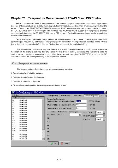
<strong>Chapter</strong> <strong>20</strong> <strong>Temperature</strong> <strong>Measurement</strong> <strong>of</strong> <strong>FBs</strong>-<strong>PLC</strong> <strong>and</strong> <strong>PID</strong> <strong>Control</strong><strong>FBs</strong>-<strong>PLC</strong> provides two kinds <strong>of</strong> temperature modules to meet the great temperature measurement applications.One kind <strong>of</strong> these modules are directly interfacing with the thermocouple, <strong>and</strong> the others are interfacing with the RTDsensor. The modules <strong>FBs</strong>-TC2/<strong>FBs</strong>-TC6/<strong>FBs</strong>-TC16 support 2/6/16 temperature channels correspondingly to connectthe J,K,T,E,N,B,R,S type <strong>of</strong> thermocouple. The modules <strong>FBs</strong>-RTD6/<strong>FBs</strong>-RTD16 support 6/16 temperature channelscorrespondingly to connect the PT-100,PT-1000 type <strong>of</strong> RTD sensor. The total temperature inputs can be exp<strong>and</strong>ed upto 32 channels at the most.By the time domain multiplexing design method, each temperature module occupies 1 point <strong>of</strong> register input <strong>and</strong> 8points <strong>of</strong> digital output for I/O addressing. The update rate for temperature reading value can be set as normal (Updatetime is 5 second, the resolution is 0.1°) or fast (Update time is 2 second, the resolution is 1°).The Winproladder provides the very user friendly table editing operation interface to configure the temperaturemeasurement, for example, selecting the temperature module, type <strong>of</strong> sensor, <strong>and</strong> assign the registers to store thereading values… As to the temperature control, it has the convenient instruction FUN86(TPCTL) to perform the <strong>PID</strong>operation to control the heating or cooling <strong>of</strong> the temperature process.<strong>20</strong>.1 <strong>Temperature</strong> measurementThe procedures to configure the temperature measurement as below :1. Executing the WinProladder s<strong>of</strong>tware2. Doubble click the System Configuration3. Doubble click the I/O configuration4. Click theTemp. configuration, there will appear the following screen<strong>20</strong>-1
. The descriptions <strong>of</strong> the temperature configuration screen.Starting Address <strong>of</strong> Configuration Table : Assign the starting <strong>of</strong> registers to store the temperature configuration table,there will allow the following inputsSpace (Without temperature configuration table)Rxxxx or DxxxxxThe configuration table will occupy 4+N <strong>of</strong> registers,where N is the number <strong>of</strong> modules.As shown the sample above, R5000~R5004 stores the table.Starting Address <strong>of</strong> Temp. Register: Assign the starting <strong>of</strong> registers to store the current temperature readingvalues, there will allow the following inputsRxxxx or Dxxxxx1 channel <strong>of</strong> temperature occupies 1 registerAs shown the sample above, R0~R5 stores the reading valuesThe resolution <strong>of</strong> reading value is 0.1°For exa. R0=1234, it means 123.4°.Starting Address <strong>of</strong> Working Register : Assign the starting <strong>of</strong> registers to reserve the working registers, there willallow the following inputsRxxxx or DxxxxxAs shown the sample above, D0~D11 are the working registers.<strong>Temperature</strong> module installation information <strong>and</strong> setup.Module #1 ~ # 8 : Display the name <strong>of</strong> the installed temperature module <strong>and</strong> the analog starting address <strong>of</strong> it's own,there are the following modulesTC6 (6 channels <strong>of</strong> thermocouple input)RTD6 (6 channels <strong>of</strong> RTD input)TC16 (16 channels <strong>of</strong> thermocouple input)RTD16 (16 channels <strong>of</strong> RTD input)TC2 (2 channels <strong>of</strong> thermocouple input): The Sensor Type field is used to assign <strong>and</strong> display the sensor type,there will have the following selectionsJ-type thermocouple (-<strong>20</strong>0~1<strong>20</strong>0℃)K-type thermocouple (-190~1300℃)T-type thermocouple (-190~380℃)E-type thermocouple (-190~1000℃)N-type thermocouple (-<strong>20</strong>0~1000℃)B-type thermocouple (350~1800℃)R-type thermocouple (0~1800℃)S-type thermocouple (0~1700℃)PT100-DIN/PT100-JIS (-<strong>20</strong>0~850℃)PT1000-DIN/PT1000-JIS (-<strong>20</strong>0~600℃)α=0.00385 for PT100-DIN/PT1000-DINα=0.003916 for PT100-JIS/PT1000-JIS<strong>20</strong>-2
.Unit <strong>of</strong> <strong>Temperature</strong>.Times <strong>of</strong> Average: Assign the unit <strong>of</strong> temperature, there have the following selectionsCelsiusFahrenheit: Assign the times <strong>of</strong> average for temperature measurement, there have thefollowing selectionsNo / 2 / 4 / 8.Scan Rate : Assign the update rate <strong>of</strong> temperature reading value, there will have the following selectionsNormal(Update time is 5 second, the measurement resolution is 0.1°) Fast (Update time is 2 second, themeasurement resolution is 1°) The resolution <strong>of</strong> reading value is always 0.1°. Note 1 : The internal format <strong>of</strong> temperature configuration table. Supposing the starting address is SR,SR+0 = A556h, it means valid temperature configuration tableSR+0 = other values, it means invalid temperature configuration tableAddress High Byte Low ByteSR + 0 A5h 56hSR + 1 Quantity <strong>of</strong> temperature modules (1~8)SR + 2SR + 3Starting address <strong>of</strong> reading valuesStarting address <strong>of</strong> working registersSR + 4 Type <strong>of</strong> sensor (#1) Module name (#1)SR + 5 Type <strong>of</strong> sensor (#2) Module name (#2)SR + 6 Type <strong>of</strong> sensor (#3) Module name (#3)SR + 7 Type <strong>of</strong> sensor (#4) Module name (#4)SR + 8 Type <strong>of</strong> sensor (#5) Module name (#5)SR + 9 Type <strong>of</strong> sensor (#6) Module name (#6)• • •• • •. The temperature configuration table occupies (4+N) registers in total;where N is the quantity <strong>of</strong> modules<strong>20</strong>-3
. Note 2 : The internal format <strong>of</strong> working registers. Supposing the starting address is WR,High ByteLow ByteWR+0b15 b8 b7 b0Exe_CodeWR+1 Sensor abnormal indicator (Sensor 15 〜 Sensor 0)WR+2 Sensor abnormal indicator (Sensor 31 〜 Sensor 16)WR+3 Total amount <strong>of</strong> TP channel Qty <strong>of</strong> <strong>Temperature</strong> ModuleWR+4 Type <strong>of</strong> sensor <strong>of</strong> Module #1 D.O. <strong>of</strong> TP Module #1WR+5 Channel No. <strong>of</strong> Module #1 A.I. <strong>of</strong> TP Module #1WR+6 Reading start <strong>of</strong> <strong>Temperature</strong> Module #1WR+7 Current channel <strong>of</strong> <strong>Temperature</strong> Module #1••••••WR+(N×4)+0 Sensor <strong>of</strong> Module #N D.O. <strong>of</strong> TP Module #NWR+(N×4)+1 Channel No. <strong>of</strong> Module #N A.I. <strong>of</strong> TP Module #NWR+(N×4)+2 Reading start <strong>of</strong> <strong>Temperature</strong> Module #NWR+(N×4)+3 Current channel <strong>of</strong> <strong>Temperature</strong> Module #NNotes:Lower byte <strong>of</strong> WR+0 : Tells the mismatch between the configuration table & installedtemperature boardb0=1, means module #1, … , b7=1, means module #8Upper byte <strong>of</strong> WR+0 : Exe_code= 00h, Idle= FFh, TP channel > 32, w/o temperature measurement= FEh, lower byte <strong>of</strong> WR+3 = 0 or > 8, same as above= 56h, already read all TP channels, measurement in progress.The working table occupies (N×4)+4 registers in total;where N is the quantity <strong>of</strong> modules<strong>20</strong>-4
<strong>20</strong>.1.1 Description <strong>of</strong> Related Special Registers for <strong>Temperature</strong> <strong>Measurement</strong>R4010 : Each bit <strong>of</strong> R4010 to tell the status <strong>of</strong> the sensor's installation.Bit0=1 means that 1 st point <strong>of</strong> temperature sensor is installed.Bit1=1 means that 2 nd point <strong>of</strong> temperature sensor is installed.••Bit15=1 means that 16 th point <strong>of</strong> temperature sensor is installed.(The default <strong>of</strong> R4010 is FFFFH)R4011 : Each bit <strong>of</strong> R4011 to tell the status <strong>of</strong> the sensor's installation.Bit0=1 means that 17 th point <strong>of</strong> temperature sensor is installed.Bit1=1 means that 18 th point <strong>of</strong> temperature sensor is installed.••Bit15=1 means that 32 th point <strong>of</strong> temperature sensor is installed.(The default <strong>of</strong> R4011 is FFFFH)When the temperature sensor is installed (the corresponding bit <strong>of</strong> R4010 or R4011 must be 1), the systemwill perform the line broken detection to the sensor. If there is line broken happened to the sensor, therewill have the warning <strong>and</strong> the line broken value will be displayed.When the temperature sensor is not installed (the corresponding bit <strong>of</strong> R4010 or R4011 must be 0), thesystem won’t perform the line broken detection to the sensor <strong>and</strong> there will not have the warning; thetemperature value will be displayed as 0.Depends on the sensor's installation, the ladder program may control the corresponding bit <strong>of</strong> R4010 <strong>and</strong>R4011 to perform or not to perform the line broken detection.<strong>20</strong>.1.2 I/O addressing <strong>of</strong> <strong>Temperature</strong> ModuleBy the time domain multiplexing design method, each temperature module occupies 1 point <strong>of</strong> registerinput <strong>and</strong> 8 points <strong>of</strong> digital output for I/O addressing. For correct I/O access, the I/O addressing <strong>of</strong>expension modules following the temperature module must be added the I/O quantity which thecorresponding module shoud have. The WinProladder provides the easy <strong>and</strong> convenient way to calculatethe I/O address for the expension modules through the on-line "I/O Numbering" operation.<strong>20</strong>-5