Faber Burner Company
Faber Burner Company
Faber Burner Company
- No tags were found...

You also want an ePaper? Increase the reach of your titles
YUMPU automatically turns print PDFs into web optimized ePapers that Google loves.
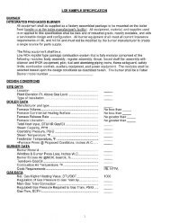
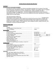
Customer:Location:Boiler Manufacturer & Type:Boiler Capacity (lb/hr):Boiler Operating Pressure (psig)Furnace Dimensions (HxWxL)<strong>Burner</strong>Paint Color:NotesFABER <strong>Burner</strong> <strong>Company</strong><strong>Burner</strong> Package SpecificationContact:Phone/Fax:FBC use onlywb - - - - - - - - - - - - -Combustion air temperature (f): Unit Handing RH LH(if a paint color has not been specified, <strong>Faber</strong> Black will be used.)Flame SafeguardFSG - - - - - -NotesCombustion ControlCC - - - -Notes-- -OptionsMain Gas Oil Train Atomizing Train Forced Draft MiscellaneousMG1 O1 A1 FD1 NEMA 4MG2 O2 A2 FD2 M1MG3 A3 FD3
<strong>Burner</strong> Packages<strong>Burner</strong> Model Identification:(Example of a Typical Specification)wb -1 -VPSSS -22 -53 - 52 - NG - 2 - 30P - 80P - 200P - NG - 3.46 -1 2 3 4 5 6 7 8 9 10 11 12 131234Number of registers per windbox.Register type: (DJ), (GVD), (VP), (VPSSS), (ULN)Register sizeHeat input first fuel: In million btu per hour ( MM BTU/HR)Our technical sales staffwill complete thisinformation for you.5Heat input second fuel: In million btu per hour (MM BTU/HR)6First fuel type:(NG)=natural gas, (2)=#2 oil, (4)=#4 oil78910111213Second fuel type: (6)=#6 oil, ** (LG)=Landfill gas, ** (X)=Other, (00)=NoneFirst fuel NOX emissions requirement or (n\a) if none required. (such as [30p] for30ppm corrected to 3% O2 dry basis or [.036l] for .036 lb mmbtu)Second fuel NOX emissions requirement or (n\a) if none required. (such as [80p] for80ppm corrected to 3% O2 dry basis or [0.1l] for 0.1 lb/mmbtu)Carbon Monoxide (co) emission requirements, or enter 400p if none required. (such as[200p] for 200ppm corrected to 3% O2 dry basis or (.15l) for .15 lb/mmbtu)Ignitor fuel type: (NG)=natural gas (2m)=#2 oil mechanical atomized(P)=Propane (2a)=#2 oil low pressure air atomizedTotal Furnace pressure at rated capacity in inches water column (inwc) with no flue gasrecirculation. (Include economizer, ducts, and any other losses.)Enter (S) if any special requirements and note requirements. Examples belowow:·Design system to engineers specification #837201·Space limitations: burner must fit in area shown on attached sheet.·Modular design: burner must be of modular design so it can be disassembled togain access to the boiler room.** A fuel analysis (ultimate analysis and higher heating value for liquid fuels, or percentvolume analysis and higher heating value for gaseous fuels) is necessary to quote ordesign a burner package.1
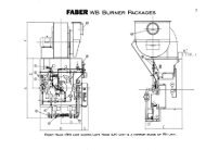
FABER WB <strong>Burner</strong> Packages2Right Hand (RH) unit shown,Left Hand (LH) unit is a mirror image of RH unit.
Standard Dimensions in Inches3RegisterSizeHeat Input(mmBtu/hr)A B C D E F G132085541 / 248271 / 4383 / 84616141 / 22785561 / 248281 / 4383 / 84616163285591 / 248293 / 4383 / 84616184098661 / 2553 / 4331 / 4483 / 85816205198661 / 2553 / 4331 / 4483 / 85816226198661 / 2583 / 4331 / 4483 / 85816231 / 27098661 / 2643 / 4331 / 4483 / 85816258098721 / 2643 / 4361 / 4483 / 86316261 / 286101721 / 270361 / 4483 / 8631628100101721 / 270361 / 4483 / 8701631129101721 / 276361 / 4483 / 8701634155101781 / 282391 / 4391 / 4* 1636175841 / 2841 / 280421 / 4421 / 4* 1638195881 / 2881 / 284441 / 4441 / 4* 1640229881 / 2881 / 286441 / 4441 / 4* 1642252901 / 2901 / 290451 / 4451 / 4* 1643265921 / 2921 / 294461 / 4461 / 4* 1644277921 / 2921 / 296461 / 4461 / 4* 1645300941 / 2941 / 298471 / 4471 / 4* 16* Indicates that a top mounted fan is not used<strong>Burner</strong> Connection Key:1 Pilot Gas Supply2 Oil Supply3 Pilot Vent4 Oil Return5 Main Gas Supply6 Main Gas Vent7 Condensate8 Atomizing Supply9 Steam Impulse Line10 Flue GasNote: Dimensions are typical. <strong>Faber</strong> <strong>Burner</strong> <strong>Company</strong> practices a policy of continuous improvement.therefore, we reserve the right to alter specifications without prior notice.
Options:MG1 = Main Gas Pressure Regulating Valve and Accessories – Includes items 10, 11, 12,13 (shipped loose for fieldinstallation) and installation drawings and manuals. If option MG1 is selected, note the gas supply pressure onthe burner package specification sheet.MG2 = Gas Strainer, Item 14, shipped loose for field installationMG3 = Gas Plug Valve with wrench, Item 15, shipped loose for field installationNEMA 4 - Changes items 1, 5, 8, 10, and 13 to weatherproof (NEMA 4)5Specifications for Main Gas Train Piping & Fittings:3” Pipe and smaller sizes = Schedule 40 pipe with 150# malleable iron threaded fittingsPipe larger than 3”= Schedule 40 pipe with standard weight butt weld fittingsGas Supply Pressure:To inlet of main gas train:Low Pressure Units:10 psig regulated, for units with heat inputs less than 120 mmBtu/hr15 psig regulated, for units with heat inputs greater than 120 mmBtu/hrIf the regulated gas supply pressure is lower than that listed above, enter (S) in position 13 ofthe burner model number and specification sheet. Note the available gas pressure on the burnerpackage.Notes:The gas flow control valve, Item 3, will be an electric or pneumatic positioning type if the combustion controlselected is one of the following:- NON Standard Parallel Positioning System- Full Metering System
FABEROil TrainPer NFPA, IRI & FM* Standards6Dashed lines indicate fieldinstalled piping and equipmentSolid lines indicate factoryinstalled piping and equipment12345678910111213141516Oil <strong>Burner</strong> Flex Hose – 321 stainless steel construction, braidedGauge Shutoff Valves – ¼” N.P.T. needle valvePressure Gauge – Weksler, 4 ½” dial, stainless steel caseGlobe Valve – Milwaukee, 300#, with replaceable seat and discCheck Valve – Milwaukee 300#Oil Safety Shutoff Valve, 2 way – ASCO General Controls, normally closed, with proof of closure switchOil Safety Shutoff Valve, 3 way – ASCO General Controls, normally closed, with proof of closure switchGate Valve – Milwaukee, 300#, with replaceable gateOil Flow Control Valve – Maxon, characterizable (12 points)Thermometer – Weksler, 3” dial, all stainless steel constructionHigh & Low Oil Temperature Switches – Mercoid, with visible set point indicationLow Oil Pressure Switch – Mercoid, with visible set point indicationPressure Gauge – Weksler, 4 ½” dial, stainless steel caseStrainer – Mueller, with 30 mesh screenGate ValveFusible linkRequired forpreheated oilOptionalEquipment
7OPTIONS:O1 = Fusible Link and Gate Valve, Items 14 and 15, shipped loose for field installation.* (The fusible link is an FM requirement. It is not required by NFPA 8501or IRI.)O2 = Replace items 6 & 7 with two Maxon safety shutoff valves and an ASCO oil return line shutoff valve.NEMA 4 - Changes items 3, 6, 7, 11, 12 & 13 to weatherproof (NEMA 4).Specifications for Oil Train Piping & Fittings: Schedule 80 pipe with 300# malleable iron threaded fittingsOil Supply Pressure:To inlet of oil train: 150 psig, for units up to 120mm Btu/hr heat input.200 psig, for units with heat inputs greater than 120 mm Btu/Hr.Low Pressure Units:If the available oil pressure is lower than listed above, enter (S) in position 13 of the burnermodel number and note the oil pressure on the burner package specification sheet.NOTES:The oil flow control valve, Item 9, will be an electric or pneumatic positioning type if the combustion control selected isone of the following:- NON Standard Parallel Positioning System- Full Metering System
FABERAtomizing TrainPer NFPA, IRI & FM Standards8Dashed lines indicate fieldinstalled piping and equipmentSolid lines indicate factoryinstalled piping and equipment12345678910111213Atomizing Media Flex Hose – 321 stainless steel construction, braidedGauge Shutoff Valves – ¼” N.P.T. needle valvePressure Gauge – Weksler, 4 ½” dial, stainless steel caseLow Atomizing Pressure Switch – Mercoid, with visible set point indicationGate Valve – Milwaukee, 300#, with replaceable gateCheck Valve – Milwaukee 300#Atomizing Media Shutoff Valve - Gould, normally closedOil Impulse Line Shutoff Valve – ¼” N.P.T. needle valveAtomizing Media Differential Pressure RegulatorLow Atomizing Supply Pressure Switch – Mercoid, with visible set point indicationStrainer – Mueller, with 30 mesh screenSteam Trap Shutoff Valve, – Milwaukee 300# gate valve, with replaceable gateSteam Trap – Sarco, balanced pressure thermostatic steam trap
14151617181920Check Valves – United, spring loadedOil Gun Purge Solenoid Valve – Gould, normally closedOil Gun Purge Pressure Regulator – FisherOil Gun Purge Isolation Valve – Milwaukee, 300# gate valve, with replaceable gatePressure Relief Valve – KunklePressure Gauge – Weksler, 4 ½” dial, stainless steel caseGauge Shutoff Valve – ¼” N.P.T. needle valveOptionalEquipment21 Pressure Regulator Isolation Valves – Milwaukee 300# gate valve, with replaceable gate22 Pressure Regulator – Fisher23 Pressure Regualtor Bypass Valve – Milwaukee 300# globe valve, with replaceable seat and disc24 Check Valves – Milwaukee 300#25 Gate Valves – Milwaukee 300#, with replaceable gateOPTIONS:A1 - Oil Gun Purge System, Items 14, 15, 16, and 17, factory installed. This system automatically cleans out the oil gunupon a “planned” oil burner shut down. When the burner control is turned off while firing oil, the unit is sent tolow fire. The pilot is energized, the oil safety shutoff valves close, and the oil gun is cleaned out with atomizingmedia. The burner shuts down at the completion of this sequence. All the safety limits are monitored during thissequence. If a limit should fail, the sequence is stopped immediately, and all the fuel valves will close.9A2 -Atomizing Steam Pressure Reducing Station – If the atomizing steam supply pressure is over 200 PSIG, a pressurereducing station will be required. This option includes items 18, 19, 20, 21, 22, and 23, factory installed on theburner.A3 -Atomizing Media Change Over Equipment – This includes items 24, and 25 shipped loose for field installation.NEMA 4 - Changes items 3, 4, 10 & 19 to weatherproof (NEMA 4).Specifications for Atomizing Media Train Piping & Fittings: Schedule 80 pipe with 300# malleable iron threadedfittings.Supply Pressure:To inlet of atomizing train:100 - 200 psig steam at 400 f or less100 - 200 psig compressed airif the available atomizing media supply pressure is greater than 200 psig option A2 will be required.
FABERGas Pilot TrainPer NFPA, IRI & FM Standards10Dashed lines indicate fieldinstalled piping and equipmentSolid lines indicate factoryinstalled piping and equipment123456789101112Pilot Gas Flex Hose – 321 stainless steel construction, braidedPilot Gas Shutoff Valve – Apollo, 3 piece, full port, ball valveLeak Test Valves – ¼” N.P.T. needle valves, plugged with ¼” pipe plugPilot Gas Shutoff Valves – Asco, normally closedPilot Gas Vent Valve – Asco, normally openPressure Gauge – Weksler, 2 ½” dialGauge Shutoff Valve – ¼” N.P.T. needle valvePilot Gas Pressure Regulator – FisherStrainer – Mueller, with 30 mesh screenPilot Gas Train Shutoff Valve – Apollo, 3 piece, full port, ball valveIgnition Transformer – 10,000 VAC output.High Temperature Ignition Cable AssemblyOPTIONS:NEMA 4 - Changes items 11 & 12 to weatherproof (NEMA 4).Specifications for Gas Pilot Train Piping & Fittings: Schedule 80 pipe with150# malleable iron threaded fittings.
OPTIONS:FD1= Forced Draft Fan Silencer (Only applies to fans with a noise level of 85 dBA or greater)– Silencer Field mounted onthe forced draft fan inlet to reduce the noise level emanating from the fan inlet to 85 dBA at 5 feet.FD2= Forced Draft Fan Motor Starter – Includes a combination motor starter with overloads and a fusible disconnect in aNEMA 12 enclosure. (shipped loose for field installation)FD3= TEFC Type Forced Draft Fan Motor – A TEFC type motor will be supplied in lieu of the standard ODP Type motor.M1 = <strong>Faber</strong> Low Draft Cutout –- Necessary on installations where the furnace operates under a negative pressure. Thissystem consists of a draft sensing element, an auxiliary relay, a time delay relay, a terminal strip, and an indicatorlight, packaged in a NEMA 12 enclosure. The indicating light is energized when a low draft condition exists in thefurnace. The low draft cutout contact is wired directly into the burner safety limits circuit. This contact opensafter a low draft condition has existed for the adjustable time delay period, which shuts down the burner on a safetylimits failure. The time delay is set during commissioning, usually 4 to 8 seconds, and the setting is protected with atamper proof cover.13NEMA 4 – Changes items 3, 5, 6, 7, & 8 to weatherproof (NEMA 4). Option FD3 must also be selected for NEMA 4. Ifoption FD2 has been purchased, the FD fan motor starter will be supplied in a NEMA 4 enclosure.Notes:If the available fd fan power supply is other than 460 vac/3 phase/60 hertz, enter (s) in the position 13 on the burnermodel number and note the available fd fan power supply on the burner package specification sheet.IFGR system, items 9, 10, 11, 12, & 13, supplied when necessary to meet project emission requirements.
Flame Safeguard SystemsFlame Safeguard Model Identification (Example of a typical spec):FSG - E110/E300 - UV - NFPA/IRI/FM - W3 - FC - S123456123456Notes:Sequencer type– Enter one of the following:E110 = Fireye E110 Flame MonitorE110 / E300 = Fireye E110 Flame Monitor with Fireye E300 Expansion ModuleSLC1= Allen-Bradley SLC500/01 programmable controller &14 point annunciatorSLC4 = Allen-Bradley SLC500/04 programmable controller & 14 point annunciatorSLC5 = Allen-Bradley SLC500/05 programmable controller & 14 point annunciatorFlame Scanner Type– Enter one of the following:UV = Self checking ultraviolet (uv) scanner & UV Flame AmplifierIR = Infrared (ir) Scanner & IR Flame AmplifierInsurance Requirements– Enter one of the following:NFPA/IRI = National Fire Protection Association and Industrial Risk InsurersNFPA/IRI/FM = National Fire Protection Association, Industrial Risk Insurers, andFactory MutualWater Level Relays– Enter one of the following:W0 = NoneW1= Low Water Cutout RelayW2 = W1 plus, Low Water Level Alarm, High Water Level Alarm, and Alarm Bell(Alarm bell rings until the water level is restored to the proper level.)W3 = W2 plus, Water Level Alarm Bell Silence Push Button, and Water LevelAbnormal Light (The push button silences the alarm bell, the light remainson until the water level is restored to the proper level.)Options– Enter as many as required, separate entries by back slashes:FC = Fuel change at low fire without shutting the unit downN4 = NEMA 4 enclosure in lieu of the standard NEMA 12 enclosureRP = Free standing remote panel in lieu of the standard burner mounted panelSF = Simultaneous firing of two fuels, an Allen-Bradley SLC 500 series processoris required for this option.Enter (S) if any special requirements and note requirementFor example: Customer requires the following dry contacts for remote annunciation,<strong>Burner</strong> On, <strong>Burner</strong> Flame Failure, High Water Level Alarm, and Low Water LevelAlarm.If the available flame safeguard power supply is other than 120 vac/3 phase/60 hertz,enter (s) in the position 6 on the flame safeguard model number, and note the availableflame safeguard power supply on the burner specification sheet.*Allen-Bradley processors are a product of Rockwell Automation Inc.14
Combustion Control SystemsCombustion Control Model Identification (Example of a typical spec):CC - SPP - MR - OO -FO-DO-OO-S1 2 3 4 56 71Combustion Control Type– Enter one of the following:Single Point PositioningSPP-MR = Jackshaft with Master Regulator (Enter this in positions 1& 2)SPP = Jackshaft with Actuator, firing rate controller, and steam pressure transmitterSingle Point Positioning + PlusSPP+P-MR = SPP-MR plus, Waste stream flow element and flow transmitter, air flow elementand flow transmitter, trim actuator, Oxygen analyzer, and Air / Fuel ratioSPP+Pcontroller (Enter this in positions 1& 2)= SPP-MR plus, Waste stream flow element & flow transmitter, Air flow element,flow transmitter, trim actuator, Oxygen analyzer, and Air / Fuel ratio controllerParallel Positioning (with Actuator Position Feedback)PP = Fuel Valve jackshaft, fuel valve actuator, air flow actuator, Firing ratecontroller, and steam pressure transmitterFull MeteringFM= Fuel and air flow elements and transmitters, flow control valves and air flow controlactuator, fuel, air, and steam pressure controllers, and steam pressuretransmitter2Type of Actuators– Enter one of the following: This position will have MR if masterregulator requiredPN= Pneumatic actuators with 4-20ma input EC= Electric actuators with 4-20ma input3Oxygen Trim– Enter one of the following: O0 = NoneO1= Oxygen Trim System4567Feedwater Control– Enter one of the following:F0 = NoneF1 = Single element feedwater control, includes feedwater controller and drum level transmitterF2 = F1 plus, steam flow element and steam flow transmitterF3 = F2 plus, feedwater flow element and feedwater flow transmitterDraft Control– Enter one of the following:D0 = None D1= Draft control, includes draft transmitter and draft controller<strong>Faber</strong> View Touch Screen Operator Interface– Enter one of the following:00=NoneFV=<strong>Faber</strong> View Touch Screen Operator Interface (Not available with SPP-MR typecombustion control option)Enter (S) if any special requirements and note requirement:For example: Use the 4-20ma signal from the existing Oxygen analyzer in the oxygen trim system,or use the 4-20ma signal from the existing Steam pressure transmitter. OR No Steampressure transmitter required; 4-20ma demand signal will be from the existing plant master.15
FABER Flame Safeguard Systems16Model: FSG-E110/E300-UV-NFPA/IRI-W3Model: FSG-SLC4-UV-NFPA/IRI-W3Right Hand (RH) unit shown. Left Hand (LH) unit is a mirror image of RH unit.
Model: FSG-E110/E300-UV-NFPA/IRI-W3Flame SafeguardModel: FSG-SLC4-UV-NFPA/IRI-W3Flame Safeguard171 Fireye ED 510 Display module2 Push buttons, lights & switches3 Alarm horn & Bell4 14 point “First Out” Annunciator5 <strong>Burner</strong> voltmeter6 Push buttons, lights & switches7 Alarm horn & Bell
SEQUENCER TYPESE110 - The Fireye E110 Flame Monitor is a microprocessor based burner management controlsystem with self-diagnostics and non-volatile memory. The Flame Monitor provides the properburner sequencing and displays the burner status on the ED510 display mounted on the flamesafeguard panel enclosure. The Flame Monitor has a fixed or “burnt in” memory and cannot befield adjusted or customized. Customization requires the addition of external timers andrelays.E110/E300 - Adding a Fireye E300 Expansion Module to the Fireye E110 Flame Monitor upgradesthe display module to a “first out” annunciator. Lockout alarm messages are displayedon the ED510 display mounted on the flame safeguard panel enclosure. This feature is veryhelpful when trouble shooting the system. For instance, if the burner “trips” due to low gaspressure, the message “3 – P Low Gas Pressure” will scroll across the display module. Withoutthe E300 expansion module, any trip due to a safety limits failure is displayed as“3 – P INTLK OPEN.”SLC1, SLC4, and SLC5 Summary – The Allen-Bradley SLC 500 series processors arerugged and dependable programmable controllers, designed to withstand harsh industrialenvironments. Because these processors are both modular in design and have severalcommunication options available, they can be easily factory configured to meet specific projectrequirements. Each unit is factory programmed and tested. The program is backed up on anEEPROM or Flash Memory module located on the processor. A 14 point “first out”annunciator is a standard offering with all Allen-Bradley SLC 500 series processors. Theannunciator has integral “Test,” “Acknowledge,” and “Reset” push buttons. All the burnersafety limits are annunciated by 1 7/16” h x 3 5/16” w lighted windows.SLC1 = Allen-Bradley SLC 5/01 processor, with EEPROM memory module, all thenecessary digital input and output cards, and a DH-485 communication port.SLC4 = Allen-Bradley SLC 5/04 processor, with Flash Memory module, all thenecessary digital input and output cards, a DH+ communication port, and anRS-232 port which can be configured to communicate with a DH-485 network.SLC5 = Allen-Bradley SLC 5/05 processor, with Flash Memory module, all thenecessary digital input and output cards, an Ethernet communication port, andan RS-232 port which can be configured to communicate with a DH-485network.18
FLAME SCANNER TYPESUV, IR Summary – All flames emit electromagnetic waves: ultraviolet (UV) radiation, visibleradiation, and infrared (IR) radiation. Typically, the flame spectrum generated by an oil or gasflame is approximately 1% UV radiation, 10% visible radiation, and 89% IR radiation. UVradiation usually originates from the first third of the flame, or the flame base. IR radiationoriginates largely from the last two thirds of the flame. IR radiation is also emitted fromsurfaces with a temperature greater than 1000ºF, such as hot refractory. Either type offlame scanner, UV or IR, can detect the presence or absence of an oil or gas flame. However,IR type flame scanners should never be used in an application where the scanner can “see” hotrefractory in a furnace.UV – Fireye self-checking UV flame scanner and UV flame amplifier.IR – Fireye IR flame scanner and IR flame amplifier.INSURANCE REQUIREMENTSNFPA/IRI – The system will be designed per the National Fire Protection Association Standardfor Single <strong>Burner</strong> Boiler Operation (NFPA 8501), and Industrial Risk Insurers standard forSingle <strong>Burner</strong> Boiler-Furnaces (IRInformation section IM.4.1.1).NFPA/IRI/FM – The system will be designed per the National Fire Protection AssociationStandard for Single <strong>Burner</strong> Boiler Operation (NFPA 8501), Industrial Risk Insurers standardfor Single <strong>Burner</strong> Boiler-Furnaces (IRInformation section IM.4.1.1), and Factory MutualEngineering Corporation standard for Oil and Gas Fired Single <strong>Burner</strong> Boilers Property LossPrevention Data Sheet (Factory Mutual 6-4 12-69).WATER LEVEL RELAYSWO = NoneW1 = One Warrick electromechanical low water cutout relay, wired into the safety limitcircuit.W2 = W1 plus, Low Water Level Alarm, High Water Level Alarm, and Alarm Bell (Alarm bellrings until the water level is restored to the proper level).W3 = W2 plus, Water Level Alarm Bell Silence Push Button, and Water Level AbnormalLight (The push button silences the alarm bell, the light remains on untilthe water level is restored to the proper level).OPTIONSFC = Fuel change at low fire without shutting the unit down. With this equipment, a fuelchange is performed as follows: The fuel change switch is turned to the on position.The unit moves to the low fire position. At low fire, the ignitor is energized. Thefuel selector switch is turned from the “current” fuel, to the “other” fuel. The fuelchange switch is turned off.N4 = NEMA 4 flame safeguard panel enclosure in lieu of the standard NEMA 12 enclosure.RP = Free Standing panel in lieu of the standard burner mounted panel.SF = Simultaneous firing of two fuels, an Allen-Bradley SLC 500 series processor isrequired for this option.19
FABER Combustion Control Systems20Model: CC-FM-02-F3-D0-00Model: CC-FM-02-F3-D0-FVRight Hand (RH) unit shown. Left Hand (LH) unit is a mirror image of RH unit.
Model: CC-FM-02-F3-D0-00Combustion Control SystemWith: FSG-SLC4-UV-NFPA/IRI-W3 Flame SafeguardModel: CC-FM-02-F3-D0-FVCombustion Control SystemWith: FSG-SLC4-UV-NFPA/IRI-W3 Flame Safeguard211 14 point “First Out” Annunciator2 <strong>Burner</strong> voltmeter3 Combustion Controllers4 Push buttons, lights & switches5 Alarm horn & Bell6 <strong>Faber</strong> view touch screen operatorinterface7 <strong>Burner</strong> voltmeter8 Main fuel trip button (emergency stop)9 Alarm horn & Bell
FABER Type “SPP-MR” Single Point Positioning Combustion Control(Typical Arrangement)22
FABER Type “SPP-PN”or “SPP-EC” Single Point PositioningCombustion Control23(Typical Arrangement)
FABER Type “PP-PN”or “PP-EC” Parallel PositioningCombustion Control24(Typical Arrangement)
FABER Type “FM-PN”or “FM-EC” Full MeteringCombustion Control25(Typical Arrangement)
COMBUSTION CONTROL TYPESINGLE POINT POSITIONING:Single point positioning systems are simple, highly reliable, and cost effective. A jackshaft is rotated by an actuator. The forced draft fan flow control damper and the fuelvalves are mechanically linked to the jack shaft. The fuel valves are characterized,over the burner firing range, to achieve the proper fuel to air ratio. This system isideal for burners with top-mounted forced draft fans that fire fuels with a relativelyconstant heating value. This system cannot be used on burners that fire two or morefuels simultaneously, or have a remote-mounted forced draft fan.SPP-MR = The jack shaft actuator in this single point positioning system is a HaysCleveland master regulator. The master regulator is a self-contained, fullyautomatic firing rate controller, combining the sensing element, response mechanism,and power actuator in one unit. A MANUAL-AUTO selector on the burner controlpanel allows switching from manual to automatic mode. In automatic mode, the jackshaft is regulated in direct proportion to the steam pressure demand signal.SPP-PN or SPP-EC = The jack shaft actuator in this single point positioning system isa pneumatically or electrically powered actuator. A pressure transmitter measuresthe steam pressure. The firing rate controller receives the signal from thepressure transmitter. A MANUAL-AUTO button on the firing rate controller faceplateallows switching from manual to automatic mode. In automatic mode, the firing ratecontroller sends a signal to the jack shaft actuator to maintain the desired steampressure set point.SINGLE POINT POSITIONING + PLUS:The single point positioning + plus system is a jack shaft system, plus a waste fuelmetering system with oxygen trim. This system is designed to burn a main fuelsimultaneously with small quantities, up to 20% of the total burner heat input, of awaste fuel stream with a varying flow rate and supply pressure. A jack shaft controlsthe fuel to air ratio of the main fuel. The waste fuel stream and total air flow aremeasured by flow transmitters. The jack shaft position is measured by a positiontransmitter. This information is sent to a Moore Products* 353 controller. Thecontroller processes this information and sends a signal to the air trim actuator. Theair trim actuator changes the length of the linkage connecting the FD fan damper to thejack shaft. By changing the length of this link, the desired fuel to air ratio ismaintained at any waste flue flow rate. An additional loop in the controller is used foroxygen trim. The oxygen trim system compensates for variations in the waste gas contentand ambient air temperature, maximizing boiler efficiency.SPP+P-MR = <strong>Faber</strong> type “SPP-MR” system described above, plus a waste stream flowelement and flow transmitter, an air flow element and flow transmitter, an air trimactuator, oxygen analyzer, and air to fuel ratio controller.SPP+P = <strong>Faber</strong> type “SPP-PN or SPP-EC” system described above, plus a wastestream flow element and flow transmitter, an air flow element and flow transmitter,an air trim actuator, oxygen analyzer, and air to fuel ratio controller.*Moore products controllers are a product of Siemens Moore P rocess Automation Inc.26
PARALLEL POSITIONING (with Actuator Position Feedback):Parallel positioning systems use two actuators, one to position the fuel valve jackshaft, and one to position the FD fan damper. A pressure transmitter measures the steampressure. The firing rate controller receives the signal from the steam pressuretransmitter. The firing rate controller sends a signal to both the fuel valve jack shaftactuator and the forced draft fan damper to maintain the desired steam pressure setpoint. The characteristics of a parallel positioning system are essentially the same asthe characteristics of a single point positioning system. Both systems rely on theposition of the fuel and air flow devices to maintain proper fuel to air ratios. The fueland air flow control devices in a parallel positioning system are linked “electronically,”as opposed to the mechanical linkage used in a single point positioning system. For thisreason, fuel and air actuator feedback signals are used to ensure that the actuators“position” properly. The system automatically shuts down if the position error betweenthe fuel and air actuators is too large. Parallel positioning systems cannot be used onburners that fire two or more fuels simultaneously.PP = The <strong>Faber</strong> parallel positioning system consists of a fuel valve jack shaft, a fuelvalve actuator, an air flow actuator, a firing rate controller, and a steam pressuretransmitter.FULL METERING:Full metering systems continuously measure the fuel and air streams, adjusting the fueland air control devices to maintain the desired fuel to air ratio. “Cross limiting” thefuel and air flow rates ensures that the air leads the fuel on load increases, and thatthe fuel leads the air on load decreases. This system will automatically shut down if thefuel-to-air ratio error becomes too large. Full metering systems can be used to firetwo or more fuels simultaneously.FM = The <strong>Faber</strong> full metering system consists of fuel and air flow elements andtransmitters, fuel flow control valves, an air flow control actuator, fuel and airflow controllers, a steam pressure controller, and a steam pressure transmitter.OXYGEN TRIM:An oxygen trim system increases the performance of any type of combustion controlsystem by allowing more precise control of the fuel to air ratio. This results inincreased boiler efficiency and lower operating costs. The oxygen trim systemcorrects for hysteresis in linkage type systems, slight changes in fuel heating value,and variations in the combustion air temperature. This system measures the excessoxygen in the flue gas and corrects the combustion air flow rate to maintain the properexcess air level.O1= If <strong>Faber</strong> type “SPP” combustion controls are selected, the following equipmentwill be supplied: Oxygen analyzer with display and probe assembly (shipped loose forfield mounting and installation), oxygen trim linear actuator, and an oxygen trimcontroller.(Oxygen trim continued on next page)27
O1 = If <strong>Faber</strong> type “PP” combustion controls are selected, the following equipmentwill be supplied: Oxygen analyzer with display and probe assembly (shipped loose forfield mounting and installation), and an oxygen trim controller.O1 = If <strong>Faber</strong> type “FM” combustion controls are selected, the following equipmentwill be supplied: Oxygen analyzer with display and probe assembly and a second loopwill be added to the air controller for oxygen trim control.FEEDWATER CONTROL:F1 = Single element feedwater control, includes a feedwater controller, and adrum level transmitter (shipped loose for field installation).F2 = Two element feedwater control, includes a feedwater controller and thefollowing items will be shipped loose for field installation: a drum level transmitter,a steam flow transmitter, and a steam flow orifice.F3 = Three element feedwater control, includes a feedwater controller. Thefollowing items will be shipped loose for field installation: a drum level transmitter,a feedwater flow transmitter, a feedwater flow orifice, a steam flow transmitter, anda steam flow orifice.FABER VIEW TOUCH SCREEN OPERATOR INTERFACE:FV = <strong>Faber</strong> view touch screen operator interface. All the indicating lights,switches, push buttons, annunciator points (if an Allen-Bradley* SLC 500 seriesprocessor is selected), and controller face plates on the flame safeguard /combustion control panel are replaced with a 12” color touch screen display. Thetouch screen interface will be configured with a minimum of 4 graphics displays.STANDARD EQUIPMENT USED IN COMBUSTION CONTROL SYSTEMS:Process Controllers: Moore** 353 Process Automation ControllersPressure Transmitters: Foxboro IGP10 or IGP20 series pressure transmitters withLCD indicator and push buttons for configuration andcalibration.Differential Pressure Transmitters: Foxboro IDP10 series differential pressuretransmitters with LCD indicator and push buttonsfor configuration and calibration.*Allen-Bradley processors are a product of Rockwell Automation Inc.**Moore products controllers are a product of Siemens Moore P rocess Automation Inc.28
FABER Type “F1” and “F2” Feedwater Control(Typical Arrangement)29Type “F1” - Single Element Type “F2” - Two Element
FABER Type “F3” Three Element Feedwater Control(Typical Arrangement)30
Your Local FABER Representative:FABER BURNER COMPANY857 Maple StreetLock Haven, PA 17745888-FABER11 E-Mail: sales@faberburnercompany.com 570-748-4009(888-322-3711) WEB: http://www.faberburnercompany.com Fax 570-748-4324