Multi-Energy X-ray Imaging with Linear CZT Pixel ... - NOVA R & D, Inc.
Multi-Energy X-ray Imaging with Linear CZT Pixel ... - NOVA R & D, Inc.
Multi-Energy X-ray Imaging with Linear CZT Pixel ... - NOVA R & D, Inc.

You also want an ePaper? Increase the reach of your titles
YUMPU automatically turns print PDFs into web optimized ePapers that Google loves.
Abstract--We have developed an x-<strong>ray</strong> image scanning<br />
detector system named NEXIS <strong>with</strong> multi-energy capability<br />
that represents significant improvements over a previous version<br />
developed for automated baggage screening. The system is built<br />
around a 1 mm pitch <strong>CZT</strong> pixel detector ar<strong>ray</strong> and a new 32channel<br />
signal processor chip called the XENA IC. The <strong>CZT</strong><br />
ar<strong>ray</strong> and XENA IC together enable x-<strong>ray</strong> detection at photon<br />
fluxes exceeding one million events per second per channel, at up<br />
to five energy levels <strong>with</strong> medium energy resolution. In the<br />
NEXIS system, the detectors are abutted to form a seamless 128<br />
mm long linear ar<strong>ray</strong> on each detector module board. Up to<br />
sixteen boards can be tiled together to form scanning arms of<br />
various lengths. The board can also accommodate the use of 0.5<br />
mm pixel pitch linear ar<strong>ray</strong>s. <strong>Multi</strong>-energy-bin images of<br />
compositionally and geometrically diverse objects have been<br />
acquired to demonstrate materials recognition via energy<br />
discrimination and image enhancement by suppression of<br />
scattered lower-energy radiation. Applications of this multienergy<br />
x-<strong>ray</strong> imaging system include security screening, medical<br />
imaging and industrial inspection.<br />
A<br />
<strong>Multi</strong>-<strong>Energy</strong> X-<strong>ray</strong> <strong>Imaging</strong><br />
<strong>with</strong> <strong>Linear</strong> <strong>CZT</strong> <strong>Pixel</strong> Ar<strong>ray</strong>s<br />
and Integrated Electronics<br />
Victoria B. Cajipe, Member, IEEE, Martin Clajus, Oded Yossifor, Ramaprabhu Jayaraman,<br />
Brian Grattan, Satoshi Hayakawa, Robert F. Calderwood and Tumay O. Tumer<br />
I. INTRODUCTION<br />
S the requirements of security screening become more<br />
stringent, the demand for high-performance radiation<br />
detectors has intensified and interest in multi-energy x-<strong>ray</strong><br />
imaging methodologies has grown [1]. A pioneering example<br />
of the latter was prototyped under project “ABIS” (Automated<br />
Baggage Inspection System) sponsored by the US Army<br />
ARDEC and the Department of Agriculture [2]. The enabling<br />
technology for ABIS was provided by <strong>NOVA</strong>’s modular<br />
detector system. This was built around custom linear <strong>CZT</strong><br />
detector pixel ar<strong>ray</strong>s read out by a proprietary signalprocessing<br />
integrated circuit (IC) embodying fast, multiple-<br />
Manuscript received November 1, 2004. This work was supported in part<br />
by the following grants: CALTIP C02-0086, CCAT # 52109B7805 and<br />
OTTC-CCAT GT30425.<br />
V. B. Cajipe, M. Clajus, R. Jayaraman, S. Hayakawa and T. O. Tumer are<br />
<strong>with</strong> <strong>NOVA</strong> R&D, <strong>Inc</strong>., Riverside, CA 92507 USA (telephone: 951-781-7332,<br />
first author e-mail: victoria.cajipe@novarad.com).<br />
O. Yossifor and B. Grattan are contractors <strong>with</strong> <strong>NOVA</strong> R&D, <strong>Inc</strong>. and can<br />
be reached using the above contact information for the first author.<br />
R.F. Calderwood was <strong>with</strong> <strong>NOVA</strong> R&D, <strong>Inc</strong>., Riverside, CA 92507 USA.<br />
He is now <strong>with</strong> Integrated Circuits Design Concepts, Santa Ana, CA 92705<br />
USA (telephone: 714-633-0455, e-mail: icdc@icdesignconcepts.com).<br />
energy-band output functions [3]-[5]. The design of the <strong>CZT</strong><br />
ar<strong>ray</strong>s was modified during subsequent efforts to achieve<br />
improved photon-counting performance under high-flux<br />
conditions [6]. More recently, a redesign of the readout IC was<br />
undertaken to enhance its energy-binning and rate capabilities<br />
and address the more practical issue of process longevity. To<br />
bring together the benefits of the optimized <strong>CZT</strong> detector and<br />
new XENA IC (X-<strong>ray</strong> ENergy-binning Applications<br />
Integrated Circuit), we developed the NEXIS (N-<strong>Energy</strong> X<strong>ray</strong><br />
Image Scanning) detector system. NEXIS supersedes the<br />
original ABIS design and incorporates features that favor<br />
product manufacturability and commercial viability.<br />
Charge<br />
Sensitive<br />
Amplifier<br />
Programmable<br />
Gain<br />
Amplifier<br />
V th5<br />
V th4<br />
V th3<br />
V th2<br />
V th1<br />
Counter 5<br />
Counter 4<br />
Counter 3<br />
Counter 2<br />
Counter 1<br />
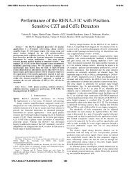
Fig. 1. Block diagram for one channel of the XENA IC.<br />
II. THE XENA IC<br />
Readout Logic<br />
Output<br />
Like its precursor chip [4], the XENA IC has 32 detector<br />
readout channels. The block diagram for one channel is shown<br />
in Fig. 1. The key characteristics of the chip are gathered in<br />
Table I.<br />
Each XENA channel consists of a shaping amplifier <strong>with</strong><br />
user-selectable shaping times between 250 ns and 4.0 µs,<br />
followed by a two-stage gain amplifier <strong>with</strong> adjustable gains<br />
and offsets. The amplifier input circuits are optimized for a<br />
detector capacitance of 3.5 pF and accept signals of either<br />
polarity. The output signals from each channel are sent to five<br />
parallel comparators operating at different thresholds; the<br />
comparator outputs are in turn connected to 16-bit digital<br />
counters. The 160 counters on each chip are read out by<br />
shifting a bit through a serial shift register, which causes the
corresponding counter to be connected to the output bus; the<br />
readout can be done in about 20 µs.<br />
Number of Channels:<br />
Data Readout:<br />
Readout Time:<br />
Counter dynamic range:<br />
Count rate capability:<br />
<strong>Energy</strong> bins per channel:<br />
Comparator Levels:<br />
Gain and offset:<br />
Input loading capacitance:<br />
Pulse shaping time:<br />
Input energy range:<br />
Input referred noise:<br />
Power consumption:<br />
Counts/5ms<br />
10000<br />
8000<br />
6000<br />
4000<br />
2000<br />
10000<br />
8000<br />
6000<br />
4000<br />
2000<br />
TABLE I<br />
KEY FEATURES OF THE XENA IC.<br />
32 + two test channels<br />
160 counters read out sequentially<br />
over 16-bit parallel data bus<br />
≈ 20 µs for all 160 counters<br />
16 bits<br />
≈ 2 x 10 6 counts/second per channel<br />
5<br />
Independent threshold voltages,<br />
≈ 1.5-3.5 V, common to all channels<br />
Digitally adjustable for each channel<br />
3.5 pF optimum<br />
Externally adjustable in two ranges,<br />
250 ns to 4.0 µs<br />
≈ 20-300 keV<br />
≈ 1000 e rms (4.5 keV for <strong>CZT</strong>)<br />
500 mW nominal<br />
Detector K45-625081-10, 0<br />
0<br />
0.00 0.10 0.20 0.30 0.40 0.50<br />
Detector K45-625081-10, 27<br />
0<br />
0.00 0.10 0.20 0.30 0.40 0.50<br />
X-<strong>ray</strong> Flux (arb. unit)<br />
Level 0<br />
Level 1<br />
Level 2<br />
Level 3<br />
Level 4<br />
Level 0<br />
Level 1<br />
Level 2<br />
Level 3<br />
Level 4<br />
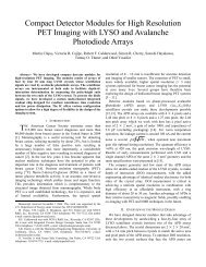
Fig. 2. Typical x-<strong>ray</strong> response curves obtained at room temperature for two<br />
pixels, number 0 and 27, in a 3 mm thick 2 x 16 pixel ar<strong>ray</strong> <strong>CZT</strong> detector (eV<br />
PRODUCTS) <strong>with</strong> the XENA IC, as a function of x-<strong>ray</strong> flux; the tube voltage<br />
was fixed at160 kVp. Level 0 to Level 4 curves refer to the five bins defined<br />
by setting the five thresholds of each XENA channel at 0.2, 0.3, 0.4, 0.5, and<br />
0.6 V, respectively, above baseline. The detector was biased to 600V.<br />
The XENA design was implemented in the AMI C5 process<br />
which is known for its long-term availability. A common<br />
commercial 144-pin CQFP package was chosen for chip<br />
assembly.<br />
The capabilities of the XENA IC can be demonstrated by<br />
using it to measure the x-<strong>ray</strong> response of a <strong>CZT</strong> pixel ar<strong>ray</strong> as<br />
a function of photon flux. Typical response curves obtained<br />
from one of our better sample 2 x 16 pixel ar<strong>ray</strong>s are plotted<br />
for each of the five energy bins in Fig. 2. Note that linear<br />
behavior is observed up to count rates of the order of two<br />
million photons per second per pixel preceding the onset of<br />
pileup.<br />
III. THE NEXIS DETECTOR SYSTEM<br />
The building block of the NEXIS detector system is the<br />
detector module board which is equipped <strong>with</strong> eight linear<br />
<strong>CZT</strong> detector ar<strong>ray</strong>s read out by eight XENA chips. The<br />
module also contains power supply circuitry, circuitry to<br />
control data acquisition, readout, and transfer, and to control<br />
the chip configuration.<br />
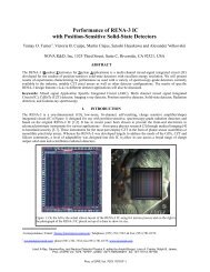
Fig. 3. a) A standard NEXIS detector module board equipped <strong>with</strong> eight 2 x<br />
16, 1 mm x 1 mm pixel pitch <strong>CZT</strong> detector ar<strong>ray</strong>s read out by eight CQFPpackaged<br />
XENA ICs, four on either side of the central strip of <strong>CZT</strong> detectors.<br />
b) A NEXIS detector scanning arm <strong>with</strong> three detector module boards forming<br />
a super-ar<strong>ray</strong> of 2 x 384 pixels; housed in a separate compartment on the right<br />
is the NEXIS arm control board.<br />
The standard NEXIS <strong>CZT</strong> detector ar<strong>ray</strong> has a 2 x 16, 1 mm<br />
x 1 mm pixel pitch pattern and is mounted on a ceramic carrier<br />
<strong>with</strong> a pin connector. The ar<strong>ray</strong>s plug into mating socket strips<br />
on the detector module board to form a seamless 2 x 128 pixel<br />
matrix. Fig. 3a displays a photograph of a standard NEXIS<br />
detector module board. Alternatively, the detector module<br />
board can be populated <strong>with</strong> homologous 1 x 32, 0.5 mm pixel<br />
a)<br />
b)
pitch <strong>CZT</strong> ar<strong>ray</strong>s. In either case, up to sixteen boards can be<br />
tiled together to build scanning arms of active lengths that are<br />
multiples of 128 mm. Fig. 3b illustrates the case of a superar<strong>ray</strong><br />
of 2 x 384 pixels.<br />
The overall NEXIS system architecture follows that of<br />
ABIS as described in [5]. A control board for each detector<br />
arm receives and processes commands from the system<br />
computer, controls the data acquisition, regulates the incoming<br />
power before distribution to the detector modules, and<br />
generates high-voltage for the <strong>CZT</strong> detectors. The detector<br />
modules and arm control board are mounted inside an<br />
aluminum enclosure (Fig. 3b). A custom PCI interface board<br />
provides the connection between the control computer and<br />
software and the NEXIS hardware. All signals between the<br />
detector arm and system computer are transmitted and received<br />
through a fiber optic connection. The NEXIS control program<br />
enables the user to configure the NEXIS system, including the<br />
XENA chips, and to acquire data <strong>with</strong> the system.<br />
In designing the printed circuit boards comprising NEXIS,<br />
the electronics components were carefully re-selected and<br />
updated to ensure parts longevity. Provisions were also made<br />
in the design to accommodate UL safety standards for<br />
grounding, high voltage isolation and EMI in anticipated<br />
production runs for the boards.<br />
IV. INITIAL IMAGING TEST RESULTS<br />
We carried out imaging tests using one NEXIS detector<br />
module board fully populated <strong>with</strong> 3mm thick, 2 x 16, 1 mm x<br />
1 mm pixel pitch <strong>CZT</strong> ar<strong>ray</strong>s (Fig. 3a). The single board<br />
detector arm was installed beneath the conveyor belt of the<br />
enclosure of our x-<strong>ray</strong> system. X-<strong>ray</strong>s were provided by a<br />
Pantak 160 HF x-<strong>ray</strong> generator <strong>with</strong> a tungsten tube operated<br />
at voltages up to 160 kV and currents up to 2.0 mA.<br />
The images obtained thus far represent only the beginning of<br />
a work program that aims to collect detailed evidence of<br />
superior performance of a multi-energy detector system in<br />
solving two important problems in x-<strong>ray</strong> imaging: automated<br />
materials recognition based on average density and effective<br />
atomic number information [7],[8]; and, elimination of<br />
radiographic scatter by energy discrimination [9]. At the time<br />
of writing this manuscript, we had just started to determine the<br />
experimental conditions that would be optimal for our<br />
purposes. Examples of our initial images are displayed in Fig.<br />
4 and Fig. 5. In Fig. 4, the inspected object is a phantom<br />
comprised of compositionally diverse items embedded in a<br />
foam-filled cylinder that can be rotated to produce pseudotomographic<br />
views. The chemical information can be extracted<br />
from the levels of g<strong>ray</strong> observed to vary between successive<br />
energy-binned images. Fig. 5 illustrates how discriminating out<br />
x-<strong>ray</strong>s <strong>with</strong> energy less than 35 keV, which produce scatter,<br />
can enhance image definition and contrast. Thorough analysis<br />
of these images and other data yet to be gathered will require<br />
development of appropriate software or adoption of existing<br />
routines. We foresee pursuing this work as a collaborative<br />
effort <strong>with</strong> parties interested in evaluating NEXIS for use in<br />
various applications or in developing tools for spectral image<br />
analysis.<br />
a)<br />
b)<br />
Fig. 4. a) Four-energy-bin radiograph of a pseudo-CT imaging phantom<br />
comprised of five compositionally different items in a foam-filled cylinder,<br />
from left to right: Mexican limes, plastic match holder <strong>with</strong> flint, small PCB,<br />
molded Semtex explosive simulant, carved piece of wood and pyrex cup. The<br />
clamp on the right serves to fix the orientation of the rotatable cylinder; the<br />
material coming out of the left end is excess foam. From top image to bottom,<br />
the energy thresholds were set approximately at 20, 35, 60 and 90 keV,<br />
respectively. b) Three-energy-bin radiographs presenting two other views of<br />
the same phantom as in a) obtained at two different rotation angles and<br />
displayed perpendicularly relative to a). From left image to right in each group<br />
of three, the energy thresholds were set approximately at 20, 35 and 60 keV,<br />
respectively. The conveyer belt speed used in all of the above was<br />
approximately 8 cm/sec.
Fig. 5. Three-energy-bin radiograph of light bulbs and a corkscrew. From<br />
left image to right in each group of three, the energy thresholds were set<br />
approximately at 20, 35 and 60 keV, respectively. Note the improved contrast<br />
and better definition in the middle image, particularly in the bounding surfaces<br />
and detailed features of the corkscrew.<br />
V. ACKNOWLEDGMENT<br />
We thank Dave Ward and Gerard Visser for their<br />
contributions to the XENA chip and NEXIS board designs,<br />
respectively.<br />
VI. REFERENCES<br />
[1] See, for example, the Proposer Information Pamphlet for the Homeland<br />
Security Advanced Research Projects Agency Broad Agency<br />
Announcement 04-02 “Detection Systems for Radiological and Nuclear<br />
Countermeasure” at http://www.hsarpabaa.com/Solicitations/BAA04-<br />
02Ver5.0._508doc.pdf.<br />
[2] See: http://qa.pica.army.mil/tqf/Homeland Defense Baggage<br />
Inspection.pdf. <strong>NOVA</strong>’s contribution was carried out under contract<br />
Number DAAA21-93-C-1014. Also see:<br />
http://www.novarad.com/pages/abis_frames.html.<br />
[3] T.O. Tümer, “Radiation detector and nondestructive inspection”, US<br />
Patent No. 5 943 388, Aug. 24, 1999.<br />
[4] M. Clajus, T.O. Tümer, G.J. Visser, S. Yin, P.D. Willson, and D.G.<br />
Maeding, “Front-End Electronics for Spectroscopy Applications (FESA)<br />
IC,” contribution to the IEEE Nuclear Science Symposium 2000, Lyon,<br />
France, October 15 – 20, 2000. See:<br />
http://www.novarad.com/pages/documents/fesa_ieee_paper_2000.pdf.<br />
[5] T.O. Tümer et al., “Preliminary results obtained from a novel CdZnTe<br />
pad detector and readout ASIC developed for an Automatic Baggage<br />
Inspection System,” contribution to the IEEE Nuclear Science<br />
Symposium 2000, Lyon, France, October 15 – 20, 2000. See:<br />
http://www.novarad.com/pages/documents/ABIS_ieee_2000.pdf.<br />
[6] M. Clajus , V.B. Cajipe, J. Bruce Glick, T. O. Tümer , G. Visser, P. D.<br />
Willson , and Y. Yang, “CdZnTe detectors for high-flux x-<strong>ray</strong> imaging”,<br />
presented at the Conference on Applications of Nuclear Techniques,<br />
Crete, June 2001. See: http://www.novarad.com/pages/documents/X<strong>ray</strong>_ICANT_2001.pdf.<br />
[7] W. Battye, D. Linderman and S. Cheung, “Development of a luggage<br />
materials database to facilitate explosives detection - Phase II”,<br />
contribution to 3rd International Symposium on Explosives Detection<br />
and Aviation Security Technologies, November, 2001, Atlantic City, NJ.<br />
[8] S. Maitrejean, D. Perion and D. Sundermann, “<strong>Multi</strong>-energy method: a<br />
new approach for measuring x-<strong>ray</strong> transmission as a function of energy<br />
<strong>with</strong> a Bremsstrahlung source- application for heavy element<br />
identification,” SPIE., vol. 3446, pp. 114-133, Jul. 1998.<br />
[9] P. Willson, M. Clajus, T.O. Tümer, G. Visser, and V. Cajipe, "<strong>Imaging</strong><br />
using energy discriminating radiation detector ar<strong>ray</strong>," invited paper<br />
presented at the 17th International Conference on the Application of<br />
Accelerators in Research and Industry, CAARI 2002, Denton, TX,<br />
November 12-- 16, 2002.